
421509 - Environmental Thermometer Extech - Free user manual and instructions
Find the device manual for free 421509 Extech in PDF.


| Product Type | Handheld Digital Thermometer / Datalogger |
| Display | 4-1/2 digit (19999), triple LCD with LED backlight |
| Thermocouple Types | K, J, T, E, R, S, N (K-type supplied) |
| Input Channels | Dual (T1 and T2) |
| Temperature Range (K-type) | -328 to 2501°F (-200 to 1372°C) |
| Resolution | 0.1°F/°C (1°F/°C above 2000°F for K/J) |
| Accuracy (K/J/T/E) | ±(0.05% rdg + 0.6°F) from -58°F to 2501°F |
| Data Logging | 16 groups × 64 points = 1024 readings |
| Data Storage | 128 manual save points |
| Interfaces | Optical RS-232 (USB via supplied cable) |
| Alarm Output | 6-pin mini DIN, 5mA@5-30VDC (external source) |
| Special Functions | Data hold, min/max/avg, relative mode, limits with audible alarm, T/C offset adjustment |
| Auto Power Off | Programmable 5 to 19999 minutes |
| Power Supply | 9V battery (100 h typical) or optional AC adaptor |
| Dimensions | 192 × 91 × 52.5 mm (7.5 × 3.6 × 2.1 in) |
| Weight | 365 g (11.7 oz) with holster |
| Operating Conditions | 32 to 122°F (0 to 50°C); <80% RH |
| Storage Conditions | -4 to 140°F (-20 to 60°C); <70% RH |
| Safety | Do not use near voltages >24V AC/DC; not for microwave ovens |
| Supplied Accessories | K-type thermocouple (4 ft, Teflon insulation), RS-232 cable, software CD, rubber holster, 9V battery |
| Replacement Parts | Thermocouples, 9V battery, AC adaptor (optional), USB cable (part #421509-USBCBL) |
| Reparability | User replaceable battery and thermocouples; refer to manual for service |
| Cleaning | Wipe with dry cloth; do not use solvents |
Frequently Asked Questions - 421509 Extech
User questions about 421509 Extech
0 question about this device. Answer the ones you know or ask your own.
Ask a new question about this device
Download the instructions for your Environmental Thermometer in PDF format for free! Find your manual 421509 - Extech and take your electronic device back in hand. On this page are published all the documents necessary for the use of your device. 421509 by Extech.
USER MANUAL 421509 Extech
Congratulations on your purchase of Extech's Dual Input, 3-Display, Hand-Held Digital Thermometer/Datalogger. This portable digital thermometer is designed to use external K / J / T / E / R / S / N type thermocouples (K-type supplied). Temperature indication follows Reference Temperature/Voltage Tables (N.I.S.T. Monograph 175 Revised to ITS-90). It features an adjustable T/C offset and an RS-232 interface for uploading data to a PC using the supplied software and cable. This professional meter, with proper care, will provide years of safe reliable service.
Safety Information
Please read the safety and operational instructions before using this device.
WARNING
To avoid electrical shock, do not use this instrument when working near voltages over 24V AC/DC. WARNING
To avoid damage or burns, do not make temperature measurement in microwave ovens.
CAUTION
Repeated flexing can break the thermocouple leads. To prolong lead life, avoid sharp bends in the leads, especially near the connector.

This symbol on the instrument indicates that the operator must refer to an explanation in this manual.
Meter Description
-
Optical RS-232 Interface
-
Thermocouple inputs
-
Mini DIN I/O port
-
Triple LCD Display
-
Keypad Overlay
-
Keypad
-
Protective rubber holster
-
Battery compartment on rear
-
12VDC Adaptor input
![1 2 3 4 5 6 7 8 9 EXTECH 421509 APO T1 °FK 78.0 78.0 344 ESC - 0 ENTER Φ C/F [Limits] [INVT] 1 ▲2 ▲3 SAVE READ LOG READ CLR ? 4 5 6 REHOLD [APO] SHIFT HOLD MAX/min [OFS] 7 8 9 TYPE T1/T2 TYPE T1/T2 [TIME] MAIN SECOND THIRD DISPLAY](/content/2026/05/955048/images/2fdf191e9c61d91e8dc1c93d03b80c2efd527eac2c57f238f3d5f493d8c4b6a6.jpg)
There are three operation modes—Normal, Shift, and Setup mode
Normal Mode
This is the default mode. The operating functions for normal mode are printed on the face of each button in white. The following functions can only be used in Normal Mode.
Power Button
The Power key turns the thermometer ON or OFF. When entering data in Setup Mode, the power off function is disabled.
[Limits] Button
The Limits function will alert the user when a measurement exceeds a specified limit. To set the limit values, refer to the limits function in the Setup Mode. Press the [Limits] button to activate the Limits function ("LIMIT" will be displayed on the LCD). When the measured temperature on the main display is higher than the High Limit (or lower than the Low Limit), the alarm beeper emits a tone and "Hi" "or "Lo" is displayed. Note: The tones for High and Low Alarms are different; the High Alarm tone is pulsed while the Low Alarm tone is continuous. Note: When reading over 2000°F using a K or J thermocouple, the reading should be multiplied by 10. (example: 2100°F x 10 = 21000). To exit the Limits function, press the [Limits] button. In this mode, the automatic power-off feature is disabled along with the following keys: REL, HOLD, & MIN MAX.
Backlight Button (INVT)
Press the backlight button to toggle the backlighting on and off.
SAVE/READ Button
The Read data function is used for reading saved data. It works in conjunction with the Save function in the Shift Mode.
- Press the SAVE/READ button to activate the read data function. The word READ will be displayed on the LCD.
- Press the "SECOND" button until the # sign is displayed in the bottom left display. The location of the read pointer within the saved data table will be displayed.
- Press the “▲3” or “▼6” button to display the next data location. Press the “▲2” or “▼5” button to increment the data location by ten.
- Press the overlay "ESC" button to deactivate the read data function.
LOG/READ Button
The read log function is used for reading logged data. It works in conjunction with the Log function in Shift Mode.
- Press the LOG/READ button to activate the read log function. The word READ will be displayed in the lower right display.
- Press the overlay "SECOND" button to rotate through the following display menus: T1, T2, GRP, and #. T1 and T2 displays the T1 or T2 saved value. GRP displays the current group number and # displays the current location of the read pointer within a selected group.
- The arrow buttons on the overlay are used for scrolling through the saved data. Press the “▲3” or “▼6” buttons to display the next data location or group.
Press the “▲2” or “▼5” buttons to increment to the next data or group location by ten. To navigate around the logged data and groups, press the overlay “SECOND” button until “GRP” appears in the display. Select the group using the arrow buttons, then press the “SECOND” button again until the “#” sign is displayed. The location of the read pointer will be displayed. Use the arrow keys to scroll through the data. - Press the overlay "ESC" button to deactivate the read log data function.
HOLD Mode (Main Display only)
Press the HOLD button to enter the Data Hold mode, the "HOLD" annunciator will display. When HOLD is selected, the thermometer freezes the reading on the main display only. Press the HOLD button again to return to the normal measurement mode.
MIN/MAX with Time Record Mode (Main Display only)
Note: Auto Power OFF and several keys (Power, C/F, REL, SET, HI/LO, TYPE, and T1, T2, T1-T2) are defeated in this mode
Press MIN MAX to enter the MIN/MAX recording mode; the meter will begin keeping track of the highest (MAX), lowest (MIN), MAX-MIN, and Average (AVG) readings. There are four displays (listed below) for this mode. Use the MIN MAX key to scroll through all four.
- When the "REC" icon is on the display (top), the meter is displaying measurements normally while it is recording.
- With the “REC MAX” icon on the display, the meter continues taking measurements but the main display shows only the highest (MAX) reading recorded. The Elapsed Time (in hours, minutes, and seconds) is shown in the lower right LCD field. The Timer shows when the MAX reading was taken.
- With the "REC MIN" icon on the display, the main display shows only the lowest reading recorded. The Time of the MIN reading is shown in the lower right LCD field.
- With the "REC MAX-MIN" icon on the display, the main display shows the difference between Max and Min.
- With the "REC AVG" icon on the display, the main display shows only the average of all the readings recorded. Note that the averaging limit is 22 hours. After 22 hours, the last average reading display is held on the LCD.
The meter emits a tone when a new minimum or maximum value is recorded. Use the HOLD button to pause recording (all values are then held). Press HOLD again to resume recording. To exit the MIN MAX mode press and hold the MIN MAX button for more than 2 seconds until the "REC" icon switches off.
T1/T2 Button (Main Display)
Press this button to select which thermocouple input configuration is represented on the main display; 'T1' will display for thermocouple input 1 or 'T2' for thermocouple 2. When the meter is turned on, it is set to the display that was in use when the meter was last powered off.
T1/T2 (Second Display)
Press this button to select which input is shown on the secondary display (lower left display); T1 for thermocouple 1 or T2 for thermocouple 2. When the meter is turned on, it is set to the display that was in use when the meter was last powered off.
T1-T2/Time (Third Display)
Press this button to select system time, date, or the differential between the two thermocouples (T1-T2) for the third display (lower right display). When the meter is turned on, it is set to the display that was in use when the meter was last powered off.
Shift Mode
The operating functions for the shift mode are printed in yellow on the buttons. When in normal mode, push the SHIFT button to switch to shift mode. The word "Shift" will be displayed in the lower right corner of the LCD. To switch back to normal mode, press the SHIFT button again.
°C/°F Key
Readings can be displayed in degrees Celsius (°C) or degrees Fahrenheit (°F). Note that the meter remembers the unit of measure when it is turned off. Press the °C/°F key to change the temperature units.
SAVE Button
The save function stores T1 and T2 measurements in up to 128 locations in non-volatile memory. Press the SAVE button to store the current reading, the word "SAVE" is momentarily displayed on the bottom right LCD to indicate that the data has been saved. Data can be read using the read function in normal mode.
LOG Button
The data log function continuously records measurement data using the stored sampling interval. The time interval is set using the interval time setup function [INTV] in the setup mode. Press the LOG button to activate the log function. "LOG" will be displayed and "MEM" will continuously flash on the LCD. There are 16 groups that are used for storing the log data and each group has 64 data locations. If the current session exceeds 64 locations, the log function will automatically use the next group to continue storing the data. A maximum of 1024 locations can be saved in one log session. Press the LOG button again to exit the data log function.
CLR ? Button
The CLR function clears all the saved and logged data in memory. When the CLR button is pressed, "MEM" is displayed and "CLR" flashes on the upper right of the LCD. Press the overlay "ENTER" button to clear all saved and logged data, or the "ESC" button to exit the function.
REL Button
Press the REL key to enter the Relative mode. The meter will store the displayed reading (main display) as a reference value and display 'REL'. All subsequent readings will now display the measured value less the stored reference value. Press the REL key again to exit the relative mode.
[APO] Button
Press the APO button to enable/disable auto power off. "APO" is displayed on the upper left of the LCD. When enabled, it will automatically turn the thermometer off if the key switch is inactive for the preset auto power off time (default time for APO is 5 minutes). The time can be programmed in Setup Mode. Press the Power button to resume operation.
Type Button (Main display
Press the TYPE button to select the thermocouple type (K, J, T, E, R, S, or N) in the main display. If the inputs of the main and second display are the same, then pressing this button will change the thermocouple type for both displays. The selected type becomes the default selection.
Type Button (Second display)
Press the TYPE button to select the thermocouple type (K, J, T, E, R, S, or N) in the second display. If the inputs of the main and second display are the same, then pressing this button will change the thermocouple type for both displays. The selected type becomes the default selection.
Setup Mode
The operating functions for the setup mode are printed between the bracket “[ ]” signs on each button. Press the SET [ ] button in normal mode to switch to the setup mode. The indicator “SET” will be shown on the left side of the display. Press SET [ ] again to return to normal mode.
Hi/Lo Limit Setup
In Setup Mode, press the [Limits] button to enter the Hi/Lo setup function. The "LIMIT", "HI", and main display will blink on the LCD and the previous settings will be displayed. Press the number buttons (printed in white) on the overlay to set Hi and Lo limit values. The button "-" (same as the ESC overlay) can be used to set a negative value. Setting is from left to right digit. Press the ENTER button to confirm each setting.
Mini DIN Hi/Lo Alarm Output
The alarm output jack (refer to Figure 1), located on the top of the meter, can be used to power external warning or switching devices when programmed Hi/Lo alarm limits are reached. To enable this function, an external power source (5 to 30VDC, 5mA max) must be used to supply power to the connected device. Connect the power source (5-30VDC) between pin 5 (+) and pin 6 (-) of the connector (refer to Figure 2). For the Hi limit output, connect a device between pin 1 (+) and pin 2 (-) (refer to Figure 3). For the Lo limit output, connect a device between pin 3 (+) and pin 4 (-) (refer to Figure 4).
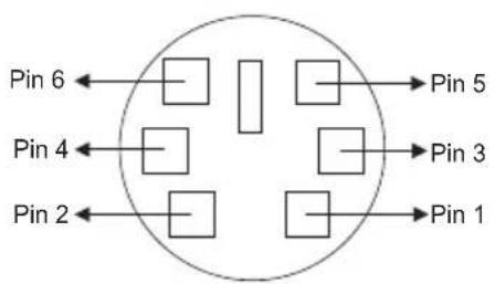
Figure 1
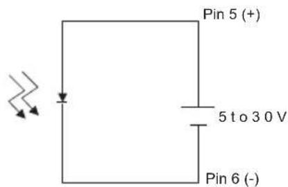
Figure 2
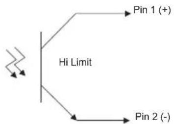
flowchart
graph TD
    A["Input"] --> B["Hi Limit"]
    B --> C["Pin 1 (+)"]
    B --> D["Pin 2 (-)"]
Figure 3
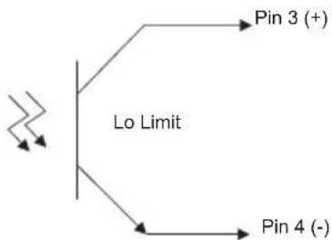
flowchart
graph TD
    A["Input"] --> B["Lo Limit"]
    B --> C["Pin 3 (+)"]
    B --> D["Pin 4 (-)"]
Figure 4
Interval Time Setting
To set up the interval time for the log function, press the [INVT] button. The indicator "INV" will blink at the top right of the LCD and previous settings are displayed. Press the number buttons (printed in white) on the overlay to change the time setting. Setting changes from left to right in the following format: HH:MM:SS. Press the ENTER button to confirm. Press the "ESC" button to exit this function.
HH: 0-23
MM: 0-59
SS: 0-59
MAX: 23:59:59
MIN: 00:00:01
Auto Power Off Time Setting
Press the [APO] button in Setup Mode. The indicator "APO" and the main display will blink on the LCD showing the previous setting. Press the number buttons (printed in white) on the overlay to change the APO time. Press the ENTER button to confirm. To exit this function without changing the setting, press the ESC button.
MAX: 19999 minutes
MIN: 0005 minutes
Thermocouple Offset Adjustment
To change the offset for T1, the main display input should be set to T1. Set the main display to T2 for adjusting the offset to T2. Press the [OFS] button to enter the offset adjustment mode. "CAL" will be displayed on the top right of the LCD and the main display will blink showing the previous setting. Press the number buttons (printed in white) on the overlay to change the offset. The resolution is 0.1°. Use the "-" button to set a negative value. Press the ENTER button to confirm.
MAX: ±1999.9°C/°F
System Time Setting
To set or change the system time, press the [TIME] button in Setup Mode. The time and date in the bottom right display will blink. Enter from left to right YY:MM:DD and HH:MM:SS. Press the number buttons (printed in white) on the overlay to change the settings. Press the ENTER button to confirm. Exit this function by pressing the ESC button.
Error messages:
If Err-02, Err-02 or Err-03 appears in the display, one of the following conditions has occurred:
Err-01: In the "SAVE" mode, the maximum recording range is 128 samples. The lower right display will show Err-01 if the maximum capacity of 128 samples has been reached.
Err-02: In the "LOG" mode, the maximum recording is 16*64=1024 samples. The lower right display will show Err-02 if the maximum capacity of the 16 groups has been reached.
Err-03: In the "READ LOG" and "READ SAVE" mode, when the main display shows 6208 and the lower right display shows "OL, Err-03", one of the following conditions has occurred::
-
There is no data in the memory.
-
The memory is full, and the meter will warn the user this is the last sample.
SAVE=128 samples
LOG=1024 samples
Battery Replacement
Replace the battery when the low battery indication symbol appears on the upper left corner of the display. To replace the battery, remove the protective rubber holster to access the battery compartment. Remove the two screws that secure the rear battery compartment cover. Remove the old battery, install a new one, and replace cover.
RS-232 PC Interface
The Model 421509 Thermometer is supplied with a Windows® software package on CD-ROM. A communications cable (meter to PC) is also supplied. The program allows the user to operate the meter remotely and view the readings from all three LCD fields on the PC monitor. The software also permits measurement data to be stored as text files on a PC. The data files can then be exported to spreadsheet or other programs for further manipulation (graphing, sorting, filing, etc.).
Connecting the Meter to a PC
Connect the Optical Interface connector to the 421509 Thermometer. The "IR2" label should be facing up. Connect the USB connector to the PC (COM port 1 -16).
PC Requirements
Note: Please visit the www.extech.com website for the latest software, user manuals, operating system compatibility, etc., as requirements and other information may change from time to time.
• 486-33 IBM compatible PC or better
- One CD-ROM drive
• Available USB port.
- Windows XP, Windows 7, Windows 8.1 and Windows 10
• USB cable part # 421509-USBCBL
Please consult the separate Software Help guide for instructions on how to use the software.
Copyright © 2013-2016 FLIR Systems, Inc.
All rights reserved including the right of reproduction in whole or in part in any form
www.extech.com
General Specifications
| Display | 4-1/2 digit (19,999), 3-Display, LCD with LED Backlighting |
| Input Protection | 24VDC or 24VAC rms maximum input on any combination of inputs. Max voltage between T1 and T2 inputs is 1V |
| Reading rate 2.5 times per second | |
| Input connectors | Accepts standard sub-miniature thermocouple connectors |
| Alarm Output 6-pin mini DIN, | max. 5mA@5 to 30VDC (external source) |
| Operating conditions 32 to 12 | °F (0 to 50°C); less than 80% RH |
| Storage conditions -4 to 140 | °F (-20 to 60°C); less than 70% RH |
| Dimensions / Weight | 7.5 x 3.6 x 2.1" (192 x 91 x 52.5mm); 11.7oz. (365g) |
| Power Supply 9V battery or optional AC Adaptor | |
| Auto Power off User programmable from 5 to 19999 minutes | |
| Battery life 100 hours typical | |
Range Specifications
| Thermocouple | Range | Resolution | |
| K type -328 to 2501 | °F (-200 to 1372°C) | 0.1°F (0.1°C),1°F >2000° | |
| J type -346 to 2192 | °F (-210 to 1200°C) | 0.1°F (0.1°C),1°F >2000° | |
| T type -328 to 752 | °F (-200 to 400°C) | 0.1°F (0.1°C) | |
| E type -346 to 1832 | °F (-210 to 1000°C) | 0.1°F (0.1°C) | |
| R type 32 to 3212 | °F (0 to 1767°C) | 1°F (1°C) | |
| S type 32 to 3212 | °F (0 to 1767°C) | 1°F (1°C) | |
| N type -58 to 2372 | °F (-50 to 1300°C) | 0.1°F (0.1°C) | |
Accuracy Specifications
| Thermocouple | Accuracy |
| K, J, T, E types | ±(0.05% rdg + 0.6°F) -58°F to 2501°F±(0.05% rdg + 1.4°F) -58°F to -346°F±(0.05% rdg + 0.3°C) -50°C to 1370°C±(0.05% rdg + 0.7°C) -50°F to -210°C |
| N type | ±(0.05% rdg + 1.6°F) -58°F to 32°F±(0.05% rdg + 0.8°F) 32°F to 2372°F±(0.05% rdg + 0.8°C) -50°C to 0°C±(0.05% rdg + 0.4°C) 0°F to 1300°C |
| R, S types | ±(0.05% rdg + 4.0°F) 32°F to 3212°F±(0.05% rdg + 2.0°C) 0°C to 1767°C |
| Temperature Coefficient | 0.1 multiplied by the accuracy per °C from 0°C to 18°C and 28°C to 50°C (32°F to 64°F and 82°F to 122°F) |
| Supplied Thermocouples | 4', type K (with teflon insulation) Max insulation temp: 500°F (260°C)Accuracy: ± 4°F (±2.2°C) or ± 0.75% of rdg (whichever is greater) from 32 to 1472°F (0 to 800°C) |
- Safety Information
- WARNING
- CAUTION
- Meter Description
- Normal Mode
- Power Button
- [Limits] Button
- Backlight Button (INVT)
- SAVE/READ Button
- LOG/READ Button
- HOLD Mode (Main Display only)
- MIN/MAX with Time Record Mode (Main Display only)
- T1/T2 Button (Main Display)
- T1/T2 (Second Display)
- T1-T2/Time (Third Display)
- Shift Mode
- °C/°F Key
- SAVE Button
- LOG Button
- CLR ? Button
- REL Button
- [APO] Button
- Type Button (Main display
- Type Button (Second display)
- Setup Mode
- Hi/Lo Limit Setup
- Mini DIN Hi/Lo Alarm Output
- Interval Time Setting
- Auto Power Off Time Setting
- Thermocouple Offset Adjustment
- System Time Setting
- Error messages:
- Battery Replacement
- RS-232 PC Interface
- Connecting the Meter to a PC
- PC Requirements
Brand : Extech
Model : 421509
Category : Environmental Thermometer