
ESO 124 HL - Antenna KATHREIN - Free user manual and instructions
Find the device manual for free ESO 124 HL KATHREIN in PDF.


| Product Type | Reflector Heating System |
| Brand | Kathrein |
| Model | ESO 124 HL (Double heating power version) |
| Suitable For | Satellite antenna CAS 124 |
| Purpose | Prevents snow and ice formation on antenna reflector |
| Heating Power | 1340 W (approx.) |
| Rated Current | 5.8 A (approx.) |
| Operating Voltage | 230 V (+6%/-10%, 50-60 Hz) |
| Over-Temperature Protection | 80°C (opener) |
| Frost Protection Temperature | +3°C |
| Protection Class | IP 65 |
| Insulation Resistance | >20 MΩ |
| Dielectric Strength | 2.5 kV |
| Weight | 2.6 kg (approx.) |
| Working Life | >10 years |
| Connection Cable Length | 3 m |
| Sensor Cable Length | approx. 4.3 m |
| Installation Temperature Range | +15°C to +30°C |
| Ambient Temperature Range | -40°C to +80°C |
| Heating Element | PTFE-insulated, 500 W/m² |
| Included Accessories | Heating mat with cable, mesh-reinforced aluminium foil (0.05x8 m), white adhesive foil segments, 5 cable ties (360 mm) |
| Recommended Controller | ESO 97 SL or ESO 99 S (must use with temperature sensor) |
| Safety Recommendation | Install residual current circuit breaker (0.03 A) per DIN VDE 0100 |
Frequently Asked Questions - ESO 124 HL KATHREIN
User questions about ESO 124 HL KATHREIN
0 question about this device. Answer the ones you know or ask your own.
Ask a new question about this device
Download the instructions for your Antenna in PDF format for free! Find your manual ESO 124 HL - KATHREIN and take your electronic device back in hand. On this page are published all the documents necessary for the use of your device. ESO 124 HL by KATHREIN.
USER MANUAL ESO 124 HL KATHREIN
Refl ector Heating System for CAS 90, CAS 120 and CAS 124
About These Instructions
This document is part of the product. These instructions describe how to install and connect the refl ector heating systems ESO 90 H, ESO 120 H, ESO 124 H and ESO 124 HL.
▶ Do not install or use the device until you have read and understood this document.
▶ Keep this document for reference throughout the service life of the device. Pass this document on to any new owner or user.
The current version of this document can be found at www.kathrein-ds.com
Features
■ Flexible special heating mat with integrated thermal insulation and PTFE-insulated heating elements
- Good heat distribution due to an optimal fit of the heating mat on the refl ector
■ Element carrier of aluminium foil, self-adhesive foil strips at the front
■ Thermal insulation made of bubble wrap with reflective layer, 4 mm
■ Built-in sensor to additionally define the heating temperature via a control
Scope of Supply
ESO 90 H
■ 1 x heating mat with 3 m cable (H05RNF) and heating temperature sensor
■ Mesh reinforced aluminium foil, 0.05 x 5 m
■ Adhesive fi Im (white) for covering the aluminium foil, 0.075 x 5 m
■ 5 x cable ties, 360 mm
ESO 120 H
■ 1 x heating mat with 3 m cable (H05RNF) and heating temperature sensor
■ Mesh reinforced aluminium foil, 0.05 x 8 m
■ Adhesive fi Im (white) for covering the aluminium foil, 0.075 x 8 m
■ 5 segments of white adhesive foil for covering the outer contours of the heating mats
■ 5 x cable ties, 360 mm
ESO 124 H, ESO 124 HL
■ 1 x heating mat with 3 m cable (H05RNF) and heating temperature sensor
■ Mesh reinforced aluminium foil, 0.05 x 8 m
■ Adhesive fi Im (white), cut into different segments, for covering the aluminium foil, 0.075 m wide
■ 4 segments of white adhesive foil for covering the outer contours of the heating mats
■ 5 x cable ties, 360 mm
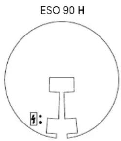


ESO 124 HL:
For exposed locations, with double the heating power compared to ESO 124 H
(L = increased performance).
Transport and Storage
▶ If possible, transport and store the heating mat in its original packaging.
▶ Protect the heating mat against moisture and mechanical damage.
▶ Transport and store the heating mat only in the permitted temperature range between -40 and +80°C. Make sure there is no condensation build-up.
Functional Description
The electric heating system prevents snow and ice formation on the antenna reflector surface which may lead to interruptions in satellite reception. The heating for the antenna consists of a special heating mat with an integrated thermal insulation and PTFE-insulated heating elements. The installed heating mat fits optimally on the reflector and guarantees good heat distribution. The heating mat has an integrated temperature switch that turns off the heating at 80°C so that the system can be operated at 230 V/50 Hz. To ensure efficient operation, we recommend the use of a control unit, which can be operated with or without the built-in sensor.
Possible system components:
| Operation without temperature sensor of the heating mat | Operation with temperature sensor of the heating mat | Operation without control possible (permanent operation) | |
| ESO 90/120/124 H ESO 005, ESO 96 S, ESO 97 S ESO 97 SL, ESO 99 S YES | |||
| ESO 124 HL NO ESO 97 SL, ESO 99 S NO |
Intended Use
The ESO 90 H, ESO 120 H, ESO 124 H and ESO 124 HL are reflector heating systems for the antennas CAS 90, CAS 120 and CAS 124. They are used to prevent snow and ice formation on the antenna reflector surface which could lead to interruptions in the satellite reception. Any other use, or failure to comply with these instructions or documentation and instructions enclosed with the devices, will result in voiding of warranty or guarantee. The following circumstances result in the loss of all warranty and liability claims towards the manufacturer:
▶ Improper installation
▶ Use of non-specified mounting materials, which cannot guarantee the mechanical reliability of the antenna system
▶ Structural changes or interference with the components and mounting accessories in the kit, which could endanger both the mechanical and functional reliability
▶ Failure to observe installation and safety instructions in these instructions
Installation and Safety Instructions

DANGER!
Danger to life from electric shock when touching electrical installations!
▶ Disconnect all devices and units from the power supply during installation.
In order to comply with the regulations for outdoor installation according to DIN VDE 0100 Part 610, it is recommended to have a residual current circuit breaker with a residual current of 0.03 A installed.
▶ Make sure that installation and connection are only carried out by qualified personnel.
▶ Make sure that modifications to electrical installations are only carried out by a specialist. Do not make any unauthorised changes yourself.

WARNING!
Risk of severe injuries during installation due to falling from or through the roof or falling parts!
▶ Wear sturdy shoes with non-slip soles.
▶ Use a working platform.
▶ Make sure that the person carrying out the installation or repair has a secure position to stand and hold on whilst working.
▶ Make sure that the person carrying out the installation or repair does not suffer from vertigo and can move around safely on the roof or installation site.
▶ Make sure that the vehicle roof is sufficiently strong and stable.
▶ Make sure that there is nobody underneath the antenna during installation/dismantling.
Installing the Reflector Heating
Required tools and equipment
■ Knife
■ Scissors
Installing the heating mat
Processing temperature
The most favourable processing temperatures (object temperature and ambient temperature) are between +15°C and +30°C. Processing below these temperatures is not recommended. Below the recommended temperatures, the adhesive may become too hard and thus not achieve the desired adhesion.
The build-up of condensation must be avoided in any case. Condensation may build up when the adhesive tape and/or the surfaces to be bonded are moved from a cold to a warmer environment. If this is the case, sufficient time must be allowed after transport and before bonding, so that all joining parts have the same temperature in the range indicated above.
- Clean and degrease the antenna back panel.
The surface to be bonded must always be dry, free from dust, grease, oil, oxides, separating agents and other contaminants. Isopropanol, ethanol, acetone, ethyl acetate, toluene or petrol can be used to remove dust, grease, oil, separating agents and other contaminants. Other standard cleaning agents that do not leave any residues are also suitable. Please observe the respective safety regulations of the manufacturers of the solvents and cleaning agents.
- Hold the heating mat on the antenna back panel to check the position.
Before final bonding, place the heating mat on the back of the antenna and check if it fits correctly.
- For affi xing it, hold the heating mat in place.

CAUTION!
Risk of material damage due to the incorrect attachment of the heating mat!
If the heating mat is not attached to the antenna correctly, it can tear when the adhesive fi lm is being removed.
▶ Make sure that the heating mat is aligned correctly. To do so, place the heating mat flush with the outer edge of the antenna and pay attention to equal distances at the antenna bracket. After the heating mat has been affixed, a correction is no longer possible!
▶ If possible, ask a second person to hold the heating mat.
-
Gradually remove the protective film from the adhesive surface and press the heating mat firmly in place.
-
Press the heating mat firmly to the antenna back panel. It can take up to 72 hours before the final adhesive strength is reached.
-
To prevent moisture and insects from entering the heating mat, adhere the mesh-reinforced aluminium foil all along the edges of the mat.
-
Clean the surface to be covered with the mesh-reinforced aluminium adhesive tape (see 1.) to ensure the greatest possible adhesive strength of the white adhesive foil.
-
Cover the aluminium adhesive tape with the white adhesive foil. Stick the outer contours of the heating mats with the segments according to the labelling on the carrier foil.
ESO 120 H: Cover the remaining contours with the enclosed adhesive foil (75 mm wide).
ESO 124 H/HL: Cover the remaining contours with cut adhesive foil (see graphics on next page).


Connecting the Cables

WARNING!
Risk of serious injury and material damage to the device!
▶ Make sure that this work is only carried out by qualified personnel.
- Run the connecting cable of the heating mat and the sensor cable along the antenna carrier to the control unit.
- Secure both cables with cable ties.
- Run the cables from the bottom through the screw connection into the control device.
- Run the mains cable from the bottom through the corresponding screw connection into the control device.
- Before connecting the cables in the control cabinet, check the heating for contact and insulation resistance (R):
ESO 90 H ESO 120 H ESO 124 H ESO 124 HL
| Contact resistance | Target value 1 | 51.6 – 167.6 Ω 70.1 | – 77.5 Ω 81.4 – 90 | Ω 37.5 – 41.5 Ω | |
| Actual value | |||||
| Insulation resistance | Target value > | 999 MΩ | |||
| Actual value | |||||
Dismantling the Reflector Heating
- Disconnect all cables leading to the control unit and the heating mat. Observe the “„Installation and Safety Instructions“ on page 2.
- Use hot air to remove the heating mat (including adhesive residues) from the back of the antenna.
- Install a new heating mat on the back of the antenna as soon as possible (see “„Installing the Reflector Heating“ on page 3).

When removing the film, adhesive residues may remain, which can only be removed entirely with considerable effort. You can install the new heating mat over these adhesive residues.
Maintenance
Check the correct attachment and firm seating of the heating mat on the reflector at regular intervals.
Repair and Replacement
KATHREIN Digital Systems GmbH
Customer Support
Eiselauerweg 13
89081 Ulm, Germany
Phone: +49 731 270-909 70
Email: support@kathrein-ds.com
Business hours (CET):
Monday to Thursday 8 am to 12 am and 12:45 pm to 5 pm
Friday 8 am to 1 pm
Technical Data
| Type | Order No. | ESO 90 H237500001 | ESO 120 H237500002 | ESO 124 H237500003 | ESO 124 HL237500005 | |
| Suitable for satellite antenna CAS 90 CAS 120 CAS 124 | |||||
| Permissible ambient temperature °C -40 to +80 | |||||
| Recommended installation temperature °C +15 to +30 | |||||
| Nominal temperature (frost protection) °C +3 | |||||
| Over-temperature protection (opener) °C +80 | |||||
| Operational voltage V 230 (+6%/-10%; 50 – 60 Hz) | |||||
| Rated current, approx. A 1.5 | 3.0 | 5.8 | |||
| Rated voltage | V | 230 | |||
| Rated power | W/m2 | approx. 500 | |||
| Heating power, approx. | W | 345 | 716 | 650 | 1340 |
| Insulation resistance | MΩ | >20 | |||
| Dielectric strength | kV | 2.5 | |||
| Protection class | IP 65 | ||||
| Working life | >10 years | ||||
| Weight, approx. | kg | 1.6 | 2.3 | 2.2 | 2.6 |
| Design and construction type acc. to | DIN VDE 0100, DIN EN 60519-1 VDE 0721-1, DIN EN 50173-4 VDE 0800-173-4 | ||||
| Corresponds to the standards | EN 61000-6-1, EN 61000-6-3, EN 1010-1, EN 60519-1, EN 60519-2 | ||||
| Excess temperature cut-out | |||||
| Design | Opener | ||||
| Position | At the antenna back panel in the top third in the middle of the heating area | ||||
| Type of connection | Connected in series to the heating element in the heating mat | ||||
| Connection cables | |||||
| Length | m | 3 | |||
| Diameter | mm2 | 3 x 1 | |||
| Sensor cable | |||||
| Length | m | approx. 4.3 | |||
| Diameter | mm2 | 2 x 0.22 – 0.25 | |||
Disposal

Electronic Equipment
Electronic equipment is not domestic waste – in accordance with directive 2012/19/EC OF THE EUROPEAN PARLIAMENT AND THE COUNCIL dated 04th July 2012 concerning used electrical and electronic appliances, it must be disposed of properly. At the end of its service life, take this unit to a designated public collection point for disposal.



- REFL ECTOR HEATING SYSTEM FOR CAS 90, CAS 120 AND CAS 124
- ABOUT THESE INSTRUCTIONS
- FEATURES
- SCOPE OF SUPPLY
- ESO 90 H
- ESO 120 H
- ESO 124 H, ESO 124 HL
- TRANSPORT AND STORAGE
- FUNCTIONAL DESCRIPTION
- INTENDED USE
- INSTALLATION AND SAFETY INSTRUCTIONS
- DANGER
- DANGER TO LIFE FROM ELECTRIC SHOCK WHEN TOUCHING ELECTRICAL INSTALLATIONS
- WARNING
- RISK OF SEVERE INJURIES DURING INSTALLATION DUE TO FALLING FROM OR THROUGH THE ROOF OR FALLING PARTS
- INSTALLING THE REFLECTOR HEATING
- REQUIRED TOOLS AND EQUIPMENT
- INSTALLING THE HEATING MAT
- PROCESSING TEMPERATURE
- CAUTION
- RISK OF MATERIAL DAMAGE DUE TO THE INCORRECT ATTACHMENT OF THE HEATING MAT
- CONNECTING THE CABLES
- DISMANTLING THE REFLECTOR HEATING
- MAINTENANCE
- REPAIR AND REPLACEMENT
- DISPOSAL
- ELECTRONIC EQUIPMENT
Brand : KATHREIN
Model : ESO 124 HL
Category : Antenna