
ROTO-1/2N7 - Drill Truper - Free user manual and instructions
Find the device manual for free ROTO-1/2N7 Truper in PDF.


| Product Type | Hammer Drill |
| Brand | Truper |
| Model | ROTO-1/2N7 |
| Code | 19324 |
| Chuck Size | 1/2" |
| Voltage | 127 V~ |
| Frequency | 60 Hz |
| Current | 7 A |
| Power | 1.2 Hp |
| Drilling Capacity (Metal) | 0.51" |
| Drilling Capacity (Concrete) | 0.51" |
| Drilling Capacity (Wood) | 0.98" |
| Speed Range 1 | 0 - 1200 RPM |
| Speed Range 2 | 0 - 3300 RPM |
| Impact Rate 1 | 0 - 20,400 strokes/min |
| Impact Rate 2 | 0 - 56,100 strokes/min |
| Duty Cycle | 50 minutes work / 20 minutes idle, max 6 hours per day |
| Insulation | Class II (Double insulation) |
| IP Grade | IP20 |
| Power Cord | 16 AWG x 2C, Type Y grip |
| Tool Build Quality | Reinforced |
| Motor Thermal Insulation | Class B |
| Safety Features | Double insulation, polarized plug, use GFCI outdoors |
| Maintenance | Carbon brush replacement, chuck replacement, lubrication at authorized center |
Frequently Asked Questions - ROTO-1/2N7 Truper
User questions about ROTO-1/2N7 Truper
0 question about this device. Answer the ones you know or ask your own.
Ask a new question about this device
Download the instructions for your Drill in PDF format for free! Find your manual ROTO-1/2N7 - Truper and take your electronic device back in hand. On this page are published all the documents necessary for the use of your device. ROTO-1/2N7 by Truper.
USER MANUAL ROTO-1/2N7 Truper
natural_image
Electrical outlet cable connected to a wall-mounted socket (no text or symbols visible)natural_image
Diagram of a device casing with a circular vent and internal components (no text or symbols)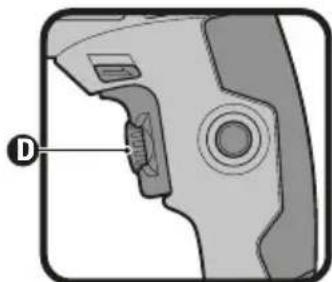
natural_image
Diagram of a mechanical component with labeled part D, showing internal structure without any text or symbols.
natural_image
Diagram of a device interior with labeled components (no readable text or symbols)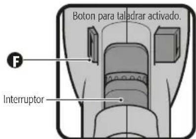
natural_image
Illustration of a TRUPER drill put tool with visible blade and grip (no text or symbols)CALLE D No. 31-A, COL. MODELO DE
ECHEGARAY, NAUCALPAN, EDO. DE MÉXICO,
C.P. 53330 TEL.: 01(55) 5371-3500
SUCURSAL CHIHUAHUA
AV. SILVESTRE TERRAZAS No. 128-11 PARQUE INDUSTRIAL BAFAR, CARRETERA MÉXICO
CUAUHTEMOC, CHIHUAHUA, CHIH.
TEL.: 01 (614) 43 40 052
SUCURSAL CULIACAN
LIBRAMIENTO BENITO JUÁREZ No. 5599 B4,
EJIDO DE LAS FLORES (LA COSTERITA),
CULIACÁN, SINALOA, C.P. 80296
CONMUTADOR: 01(667) 760-5747
SUCURSAL GUADALAJARA
ADOLF BERNARD HORN No. 6800,
TLAJOMULCO DE ZUÑIGA, JALISCO, C.P. 45655
CONMUTADOR: 01(33) 3606-5290
SUCURSAL LAGUNA
CALLE METAL MECÁNICA No. 280, PARQUE
INDUSTRIAL ORIENTE, TORREÓN, COAHUILA,
C.P. 27278 CONMUTADOR: 01(871) 209-6823
SUCURSAL MÉRIDA
Power Requirements 3

General Power Tool Safety Warnings 4

Safety Warnings for Drills and Hammer Drills 5
Parts 6
Assembly 6
Start Up 7
Maintenance 8
Notes 9
Authorized Service Centers 10
Branches 12
Warranty Policy 12

CAUTION
To gain the best performance of the tool, prolong the duty life, make the Warranty valid if necessary, and to avoid hazards of fatal injuries please read and understand this Manual before using the tool.
Keep this manual for future references.
The illustrations in this manual are for reference only. They might be different from the real tool.

ROTO-1/2N7
| Code | 19324 | |
| Description | Hammer Drill | |
| Chuck | 1/2" | |
| Voltage Frequency 127 V~ | 60 Hz | |
| Current | 7 A | |
| Power | 1,2 Hp | |
| Drilling Capacity | Metal: 0,51" | Concrete: 0,51" | Wood: 0,98" | |
| Speed | 1: 0 - 1 200 RPM 2: 0 - 3 300 RPM | |
| Impact | 1: 0 - 20 400 strokes/min 2: 0 - 56 100 strokes/min | |
| Duty Cycle | 50 minutes' work per 20 minutes idle. Maximum 6 hours per day | |
| Conductors | 16 AWG x 2C with insulating temperature of 221 °F | |
| Insulating | Class II | IP Grade IP20 |
Power Cord Grips used in this product: Type "Y".
Tool Build Quality: Reinforced
Thermal insulation on motor winding: Class B
WARNING
Avoid the risk of electric shock or severe injury. When the power cable gets damaged
it should only be replaced by the manufacturer or at a
TRUPER® Authorized Service Center.
The build quality of the electric insulation is altered if spills or liquid gets into the tool while in use.
Do not expose to rain, liquids and/or dampness.
WARNING
Before gaining access to the terminals all power sources should be disconnected.

Power Requirements
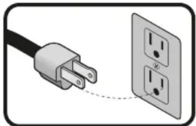
WARNING Tools with double insulation and reinforced insulation are equipped with a polarized plug (one prong is wider than the other). This plug will only fit in the right way into a polarized outlet. If the plug cannot be introduced into the outlet, reverse the plug. If it still doesn't fit, call a qualified electrician to install for you a polarized outlet. Do not alter the plug in any way. Double insulation eliminates the need of both a grounded third power cord with three prongs or a grounded power connection.
natural_image
Electrical outlet diagram showing a power plug connected to two socket outlets (no text or labels)WARNING When using an extension cable, verify the gauge is enough for the power that your product needs. A lower gauge cable will cause voltage drop in the line, resulting in power loss and overheating. The following table shows the right size to use depending on cable's length and the ampere capability shown in the tool's nameplate. When in doubt use the next higher gauge.
Ampere Capacity
| From 0 and up to 10 A |
| From 10 and up to 13 A |
| From 13 and up to 15 A |
| From 15 and up to 20 A |
Number of Conductors
| 3 (one grounded) |
Extension Gauge
| From 6 ft to 49 ft | | Higher than 49 ft |
| 18 AWG | 16 AWG |
| 16 AWG | 14 AWG |
| 14 AWG | 12 AWG |
| 8 AWG | 6 AWG |
* It is safe to use only if the extensions have a built-in artifact for over current protection.
AWG = American Wire Gauge - Reference NMX - J - 195 - ANCE - 2006
WARNING When operating power tools outdoors, use a VOLTECK grounded extension cable labeled "For Outdoors Use". These extensions are especially designed for operating outdoors and reduce the risk of electric shock.

WARNING! Read carefully all safety warnings and instruction listed below. Failure to comply with any of these warnings may result in electric shock, fire and / or severe damage. Save all warnings and instructions for future references.
Work area
Keep your work area clean, and well lit.
Cluttered and dark areas may cause accidents.

Never use the tool in explosive atmospheres, such as in the presence of flammable liquids, gases or dust.
Sparks generated by power tools may ignite the flammable material.

Keep children and bystanders at a safe distance while operating the tool.
Distractions may cause loosing control.

Electrical Safety
The tool plug must match the power outlet. Never modify the plug in any way. Do not use any adapter plugs with grounded power tools.
Modified plugs and different power outlets increase the risk of electric shock.

Avoid body contact with grounded surfaces, such as pipes, radiators, electric ranges and refrigerators.
The risk of electric shock increases if your body is grounded.
Do not expose the tool to rain or wet conditions.
Water entering into the tool increases the risk of electric shock.
Do not force the cord. Never use the cord to carry, lift or unplug the tool. Keep the cord away from heat, oil, sharp edges or moving parts.
Damaged or entangled cords increase the risk of electric shock.
When operating a tool outdoors, use an extension cord suitable for outdoor use.
Using an adequate outdoor extension cord reduces the risk of electric shock.
If operating the tool in a damp location cannot be avoided, use a ground fault circuit interrupter (GFCI) protected supply.
Using a GFCI reduces the risk of electric shock.
Personal safety
Stay alert, watch what you are doing and use common sense when operating a tool. Do not use a power tool while you are tired or under the influence of drugs, alcohol or medication.
A moment of distraction while operating the tool may result in personal injury.
Use personal protective equipment. Always wear eye protection.
Protective equipment such as safety glasses, anti-dust mask, non-skid shoes, hard hats and hearing protection used in the right conditions significantly reduce personal injury.


Prevent unintentional starting up. Ensure the switch is in the "OFF" position before connecting into the power source and / or battery as well as when carrying the tool.
Transporting power tools with the finger on the switch or connecting power tools with the switch in the "ON" position may cause accidents.
Remove any wrench or vice before turning the power tool on.
Wrenches or vices left attached to rotating parts of the tool may result in personal injury.
Do not overreach. Keep proper footing and balance at all times.
This enables a better control on the tool during unexpected situations.
Dress properly. Do not wear loose clothing or jewelry. Keep hair, clothes and gloves away from the moving parts.
Loose clothes or long hair may get caught in moving parts.

If you have dust extraction and recollection devices connected onto the tool, inspect their connections and use them correctly.
Using these devices reduce dust-related risks.
Power Tools Use and Care
Do not force the tool. Use the adequate tool for your application.

The correct tool delivers a better and safer job at the rate for which it was designed.
Do not use the tool if the switch is not working properly.
Any power tool that cannot be turned ON or OFF is dangerous and should be repaired before operating.
Disconnect the tool from the power source and / or battery before making any adjustments, changing accessories or storing.
These measures reduce the risk of accidentally starting the tool.
Store tools out of the reach of children. Do not allow persons that are not familiar with the tool or its instructions to operate the tool.
Power tools are dangerous in the hands of untrained users.

Service the tool. Check the mobile parts are not misaligned or stuck. There should not be broken parts or other conditions that may affect its operation. Repair any damage before using the tool.
Most accidents are caused due to poor maintenance to the tools.

Keep the cutting accessories sharp and clean.
Cutting accessories in good working conditions are less likely to bind and are easier to control.
Use the tool, components and accessories in accordance with these instructions and the projected way to use it for the type of tool when in adequate working conditions.
Using the tool for applications different from those it was designed for, could result in a hazardous situation.
Service
Repair the tool in a TRUPER Authorized Service Center using only identical spare parts.
This will ensure that the safety of the power tool is maintained.
Select the Right Bit
CAUTION • Select the right bit for the material.
This reduces the risk of severe injuries and makes the work faster.
- When drilling concrete or stone, use bits specifically dedicated for concrete.
- For metal or plastic, use bits dedicated for metal work. Measurements encompass a 0,031" (0,047" minimum for a 0,5" chuck) up to the chuck maximum capacity.
- To work on wood, select regular bits dedicated for wood work. In any event, to drill orifices 0,25" or smaller, use bit to work on metal.
- Do not try to use bits exceeding the chuck capacity.
Before Operating the Hammer Drill
• Take your time assessing the job to carry out. Make sure you watch all the necessary caution measures before you start drilling.
WARNING • Adjust correctly the bit into the chuck. Remove the chuck key before starting to drill. If the key is not removed, it can shoot out with great speed and cause severe injuries.
DANGER • Before drilling into a wall, floor or ceiling, make sure there are no hidden objects like cables, wiring or pipes.
DANGER • Double check the switch is OFF (see page 7, Strat Up and Operation Control) before connecting the tool. Otherwise, it will star unexpectedly and could cause severe injuries.
CAUTION • Turn OFF and disconnect the tool before reversing the chuck rotation direction and / or replacing the bit.

Wrong Way to Operate the Hammer Drill
While Operating the Hammer Drill
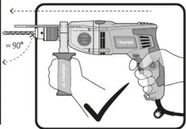
- Hold the tool using both the main handle and the auxiliary handle if supplied with the tool. Keep in mind that losing control can causes severe personal in
- Hold the tool by the insulated surfaces, emphasizing when carrying out jobs where the cutting bit may contact hidden wires or its own power cable. Contact with a power conducting cable, electrify the metal parts of the tool and cause an electric shock to the operator.
- Do not force the tool to excessive force.

CAUTION • If the bit gets stuck in the work piece, shut off the hammer drill immediately! Then, remove the bit out from the work piece. Do not try to remove a stuck bit by turning it On and Off the tool to accelerate the drilling job. • Do not exercise too much pressure on the tool in order to accelerate the drilling. Otherwise, the bit gets damaged and the efficiency will decrease as well as the useful life of the tool.
WARNING • The bigger the diameter of the bit, the higher the reactive force. It may cause losing control of the tool. To prevent this possibility, hold the tool firmly with both hands and stand well balanced while drilling at 90°.
- stay alert and prepared to relax the force when the bit drills through metal. Sudden movements may break the bit or damage the tool body.
CAUTION • Do not touch the bit or the orifice right after drilling. Allow cooling down time to manipulate. Do not try to cool down using water or oil.
- Avoid setting the tool in a place where there may be particles and / or dust immediately after using it. These particles may be absorbed inside the tool mechanism and damage it.
- Wear hearing protection when using the hammer drill. Exposure to noise may cause hearing loss.
- Wear anti-dust mask and a dust extracting equipment. Remember that working materials such as asbestos, paint with lead, additives, some kinds of wood, metals or minerals is highly toxic.
- Wear safety goggles.


Right Way to Operate the Hammer Drill

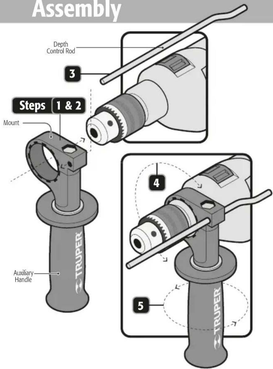
Assembly
- Turn the auxiliary handle in a clockwise direction while released so that the opening in the mount gets through freely over the chuck.
- Insert the hammer drill head through the auxiliary mount.
- Insert the depth control rod into the mount orifice.
- Rotate the auxiliary handle together with its mount until is set in the right position to operate the tool. The auxiliary mount is secure when the handle notches assemble in the gearbox.
- Turn the auxiliary handle to firmly set the mount onto the hammer drill head.
Start Up

TRUPER®
Bit Fitting
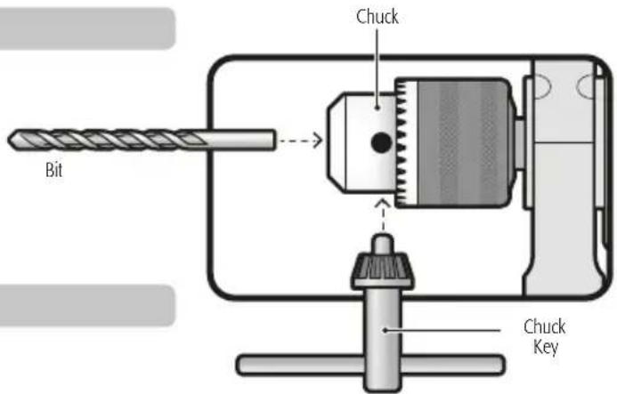
- Put the bit into the chuck until it stops. Fasten with the chuck key and tighten the chuck alternatively into each of the orifices.
WARNING • Clean burr and any other foreign object from the bit and the chuck. Otherwise, the bit cannot be tight and could cause personal injuries.
Start Up and Operation Control
- Intermittent operation:
Connect the plug into the power inlet. Press the switch (A) to start the hammer drill. To stop, just release the switch.
• Continuous Operation:
Connect the plug into the power inlet. Press the switch (A) and block it pressing the continuous use button (B). To stop, press and then, release the switch.
Speed Range Control
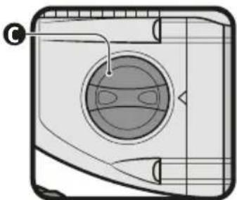
- The tool speed can be changed with the mechanical speed selector (C) shown on one side of the tool. - For lower speed adjust selector into position 1. - For higher speed adjust selector into position 2. - When selecting the speed range, the possibility of controlling each range, as described later, is not affected.
CAUTION • Do not turn the mechanical speed selector while the tool is running.
Speed Control
- The tool can operate in different speeds. These can be selected adjusting the speed control (D) built in the switch. - Turn the speed control in a clockwise direction to increase the Hammer Drill speed and torque. - Turn in a counterclockwise direction to decrease speed and torque.
Changing From Hammer Drill To Drill
- To drill concrete, floor tile or materials of similar hardness, move the impact-rotation selector (E) all the way towards the ➕ IMPACT mark. The bit will hit the material while rotating at the same time. - To drill metal, wood or plastic, move the impact-rotation selector completely towards the ◀ DRILL to make the bit rotate onto the material.
WARNING Do not try to drill metal, wood or plastic with the hammer drill into IMPACT mode setting (selector towards ↩). Otherwise the tool efficiency will lessen and the bit tip gets damaged.
Rotation Direction
- To have the bit rotating forward and drill, press the rotation selector (F), the button with the arrow pointing the chuck. - Turn in reverse and habilitate the screwdriver press the button with the arrow pointing the Hammer Drill handle.
WARNING er use the tool in reverse when having the impact - rotation selector into the IMPACT position (selector towards ←). Otherwise, the impact system will be severely damaged.

natural_image
Diagram of a device casing with a circular vent and internal structure (no text or symbols)
natural_image
Diagram of a mechanical component with labeled part D, showing internal structure without any text or symbols.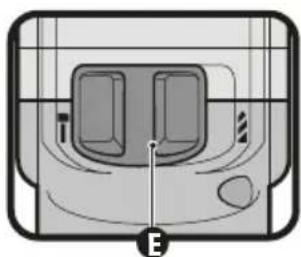
natural_image
Diagram of a device with two ports and a labeled point E, no readable text or symbols present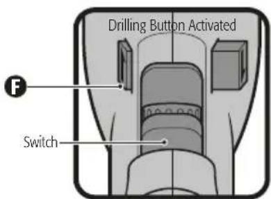
Adjusting Auxiliary Handle And Depth Control Rod
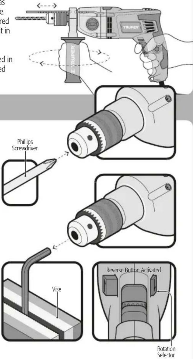
- To set the auxiliary handle into the right position to operate as hammer drill turn the auxiliary handle as indicated in the figure. When the auxiliary handle mount is loose, turn it into the desired position. Turn the auxiliary handle in a reverse direction to fix it in the new position.
- To move the depth control rod, loosen the frame as explained in the previous paragraph. Once loose push the rod to the desired depth. Tighten the auxiliary handle to fix the rod into the new position.
Maintenance
Chuck Replacement
- Remove the auxiliary handle and pen the chuck jaws all the way.
- Using a screwdriver remove the left-threaded safety screw with a clockwise movement.
- Fit the long side of an "L" Allen key (not included) in a vise and insert the short side of the "L" Allen key (not included) to the chuck. Close the jaws.
- Move the rotation selector lever into the reverse position (see page 7, Rotation Direction) and fastening with a firm hand activate the hammer drill. The chuck will be released with the turn.
- Set the new chuck threading into the hammer drill thread until it stops.
- Open the jaws fully and thread the screw in a counter-clockwise position. Tighten with a screwdriver.
Cleaning And Care
- To guarantee adequate motor cooling, always keep slots clean and free of obstructions.
- Regularly inspect all the assembly screws. Double-check they are properly tighten. If any screws are loose, tighten immediately.
Service
- Servicing tools should only be made in a TRUPER Authorized Service Center. Service and maintenance performed by non-qualified people may be dangerous and can lead to personal injuries. It also makes the product Warranty void.
Lubrication
- We recommend lubricating the tool transmission every carbon brush replacement in a TRUPER® Authorized Service Center.
Carbon Brush Replacement
- Carbon brushes shall be checked periodically. When showing signs of wear go to a TRUPER Authorized Service Center to have both carbon brushes replaced.
- When replaced, ask the technician to inspect if the new carbon brushes move freely in the carbon brush housing. Ask to turn on the tool during 5 minutes to even the contact in the carbon brushes and the commuter.
- Use only original TRUPER® spare carbon brushes, designed specifically with the right strength and electric resistance for each type of motor. Carbon brushes with different specifications may damage the motor.
- When replacing carbon brushes, always change both.

natural_image
Side view of a TRUPER electric drill with visible blade and grip (no text or symbols)In the event of any problem contacting a Service Center, please see our webpage www.truper.com to get an updated list, or call our toll-free numbers 01(800) 690-6990 or 01 (800) 018-7873 to get information about the nearest TRUPER Authorized Service Center.
AGUASCALIENTES
671615 SUPER TOOLS
ZARAGOZA NO. 1205, COL. EL SOL, AGUASCALIENTES, AGS. TEL.: 01(449) 996-5978
BAJA
670796 CONTRURENTAS
CALIFORNIA SUR
PROL. I. ZARAGOZA Y MÁRQUEZ DE LEÓN,
COL. 5 DE FEBRERO, SAN JOSÉ DEL CABO, BCS
TEL.: 01(624) 142-4595
CHIHUAHUA 670032 PROVIND
AV. COLEGIO MILITAR No. 4307 A, COL. NOMBRE DE DIOS C.P. 31100, CHIHUAHUA, CHIH. TEL.: 01(614) 424-4000
671530 FERRETERÍA AMAYA S.A. DE C.V.
AV. ORTIZ MENA No. 81, COL. CENTRO C.P. 33800
PARRAL, CHIH. TEL.: 01(627) 522-2600
COAHUILA 670712 INDUSTRIAL FERRETERA DE MONCLOVA, S.A. DE C.V. BLVD. HAROLD R. PAPE No. 1000, COL. CENTRO C.P. 25700 MONCLOVA, COAH. TEL.: 01(866) 632-0174 FAX: 01(866) 633-0719
COLIMA 671742 SURTIDORA DE FERRETERÍA AV. ANTONIO LEAÑO ÁLVAREZ No. 527 COL. PONCIANO ARRIAGA. TECOMÁN, TEL.: 01(313) 324-2000 y 7666 FAX: 325-2700
CHIAPAS 671770 TORNILLOS Y HERRAMIENTAS PINEDA 17
PONIENTE No. 20-A, COL. CENTRO TAPACHULA, CHIAPAS
TEL.: 01(962) 626-2807
671709 FERRETERA MANDIOLA, S.A. DE C.V. 5a
NORTE PONIENTE No. 1615-B, COL. MOCTEZUMA,
C.P. 29000, TUXTLA GUTIÉRREZ, TEL.: 01(961) 602-1544
671747 CENTRO DE SERVICIO DEL SURESTE
LIBRAMIENTO SUR ORIENTE S/N km 6.5
COL. TRABAJADORES, TUXTLA GUTIÉRREZ, CHIAPAS
TEL.: 01(961) 223-2350
670515 FERRETERÍA CASUA
RAMÓN CORONA No. 72, COL. BARRIO SANTA LUCÍA C.P.
29250, SAN CRISTOBAL DE LAS CASAS, CHIS.
TEL.: 01(967) 678-6283
671601 MATERIALES DE CONSTRUCCIÓN DE LOS ALTOS, S.A. DE C.V. FRANCISCO I. MADERO No.5, COL. CENTRO, C.P. 29200, SAN CRISTOBAL DE LAS CASAS, CHIS.
671730 MATERIALES Y ACEROS BALAM S.A.
PERIFERICO NORTE-PONIENTE No. 50 COL. BISMAR, SN.
CRISTOBAL DE LAS CASAS TEL.: 01 (967) 678-6162 y 7422
670781 PREFABRICADOS DE PALENQUE, S.A. DE C.V.
km 1 CARRETERA PALENQUE - PAKAL-NÁ S/N ENTRADA
LIENZO CHARRO C.P. 22960, PALENQUE, CHIS. TEL.: 01
(916) 345-1523 | 345-1533
MEXICO 671829 EL FUERTE DE LAS HERRAMIENTAS S.A. DE CITY C.V. PONIENTE 140 No.618 LOCAL B, COL. INDUSTRIAL VALLEJO, AZCAPOTZALCO, C.P. 02300 TELS.: 01(55) 5587-7959 y 7731
670995 EL MONSTRUO DE CORREGIDORA S.A. DE C.V. CORREGIDORA No.22, COL. CENTRO C.P. 06060 CIUDAD DE MÉXICO TEL.: 01(55) 5522-4861 | 71 y 01(55) 5522-5031, FAX: 01(55) 5522-5021
671370 ADMINISTRADORA FERRETERA, S.A. DE C.V.
CORREGIDORA No. 76-A, COL. CENTRO C.P. 06060
CIUDAD DE MÉXICO TEL.: 01 (55) 5522-9976 FAX: 01(55)
5522-9966
671131 CERRADA PINO SUAREZ No. 24, COL. ZONA ESCOLAR C.P. 07230, GUSTAVO A. MADERO, CIUDAD DE MÉXICO TEL.: 01(55) 2207-0882
671137 INGENIERÍA SUMINISTROS Y SERVICIOS
INDUSTRIALES CALZADA DE GUADALUPE No.525-A,
COL. ESTRELLA, C.P. 07810, GUSTAVO A. MADERO,
CIUDAD DE MÉXICO TEL. Y FAX: 01(55) 5577-9331 | 5781-7079
DURANGO 670350 TORNILLOS ÁGUILA, S.A. DE C.V. MASURIO No. 200 ESQUINA GALIO, COL. LUI ECHEVERRIA C.P. 34250, DURANGO, DGO. TEL.: 01(618) 817-1946 | 818-2655
671671 ENRIQUE CARROLA ANTUNA NO. 406 COL. CIÉNEGA, DURANGO, DGO. TEL.: 01(618) 825-2710
ESTADO DE 671600 ABC DE MATERIALES, S.A. DE C.V. MÉXICO VENUSTIANO CARRANZA No. 104 COL. LOS ÁNGELES TOTOLCINGO, ACOLMAN, EDO. DE MÉXICO TEL.: 01(55) 2958-8504
671723 FERRETERA TECAMAC S.A. DE C.V. CARR. MEXICO-PACHUCA km 37.5 TECAMAC, EDO. DE MÉXICO. TEL.: 5934-6396 Y 5934-6271
671765 TLAPALERIA CRUZ AV. CUAUHTEMOC No. 3 COL. BO. SAN JOSÉ, TEQUIXQUIAC, TEL.: 591-91-203-44
671025 SERVICIO Y VENTA DE HERRAMIENTAS VG AV. DE LOS MAESTROS No. 14, COL. LEANDRO VALLE C.P.54040, TLANEPANTLA DE BAZ, EDO. DE MÉXICO, TEL.: 01(55) 2628-3120 Y FAX: 01(55) 5398-2104
670050 ABRASIVOS Y SOLDADURAS ESPECIALES DE TOLUCA ISABEL LA CATÓLICA SUR No. 101 ESQ. MIGUEL HIDALGO COL. STA. CLARA C.P. 50090, TOLUCA, EDO. DE MÉXICO, TEL.: 01(722) 773-1117 | 773-1116 | 214-9458, FAX: 01(722) 215-2145
This product, its parts and components have a three year cover against any defects in material and/or workmanship as well as its function, without expense for the customer. This warranty excludes the following: 1) when product is used under different from normal conditions; 2) usage in breach of the operating manual furnished or; 3) when this product has been altered or repaired by personnel not certified by TRUPER.
This warranty shall be effective with the supplier selling the product, or at TRUPER Authorized Service Centers listed in this manual.
This warranty shall be effective when presenting the product and the valid Warranty policy duly stamped by the supplier or the proof of purchase.
To comply with this warranty, Truper will cover transportation expenses in case consumer's address is out of range from TRUPER® Authorized Service Centers listed herein or at the website www.truper.com or at our toll-free numbers: 01 (800) 690-6990 or 01(800) 018-7873.
In the event of any problem regarding the validity of this warranty please call toll-free numbers mentioned above.
Parts, components, consumables and accessories when applicable may be acquired at TRUPER Authorized Service Centers listed herein.
Stamp of the business:

3 YEARS
Date of purchase:
Imported by: TRUPER, S.A. de C.V.

- SUCURSAL CHIHUAHUA
- SUCURSAL CULIACAN
- SUCURSAL GUADALAJARA
- SUCURSAL LAGUNA
- SUCURSAL MÉRIDA
- CAUTION
- WARNING
- Power Requirements
- Work area
- Electrical Safety
- Personal safety
- Power Tools Use and Care
- Service
- Select the Right Bit
- CAUTION • Select the right bit for the material.
- Before Operating the Hammer Drill
- While Operating the Hammer Drill
- Assembly
- Start Up
- TRUPER®
- Bit Fitting
- Start Up and Operation Control
- Speed Range Control
- Speed Control
- Changing From Hammer Drill To Drill
- Rotation Direction
- Adjusting Auxiliary Handle And Depth Control Rod
- Maintenance
- Chuck Replacement
- Cleaning And Care
- Lubrication
- Carbon Brush Replacement
Brand : Truper
Model : ROTO-1/2N7
Category : Drill