USER MANUAL DPC6410 MAKITA
Instruction and Safety Manual
for Gasoline Power Cuts (page 2 - 30)
natural_image
Line drawing of a chain-linking machine with handle and mounting bracket (no text or symbols)
DPC6410, DPC6411
DPC7310, DPC7311
WARNING!
Read and understand this Manual. Always follow safety precautions in the Instruction and Safety Manual. Improper use can cause serious injury!
The engine exhaust from this product contains chemicals known to the State of California to cause cancer, birth defects or other reproductive harm. Preserve this Manual carefully!
ATTENTION!
MAKITA U.S.A, Inc warrant to the initial retail purchaser and each subsequent owner, that this utility equipment was designed, built, and equipped to conform at the time of initial sale to all applicable regulations of the U.S.
Environmental Protection Agency (EPA), and that the engine is free of defects in materials and workmanship which would cause this engine to fail to conform with EPA regulations during its warranty period.
For the components listed under PARTS COVERED, the service dealer authorized by MAKITA will, at no cost to you, make the necessary diagnosis, repair, or replacement necessary to ensure that the engine complies with applicable U.S. EPA regulations.
EMISSION COMPONENT DEFECT WARRANTY PERIOD
The warranty period for this engine begins on the date of sale to the initial purchaser and continues for a period of 2 years.
PARTS COVERED
Listed below are the parts covered by the Emission Components Defect Warranty. Some of the parts listed below may require scheduled maintenance and are warranted up to the first scheduled replacement point for that part.
Fuel Metering System
Carburetor and internal parts
Fuel filter, if applicable
Throttle stopper, if applicable
Choke System, if applicable
Ignition System
Spark plugs
Flywheel Magneto
Ignition Coil
Air Induction System
Air cleaner plate, Air filter
Air cleaner case, Intake manifold
Miscellaneous Items Used in Above Systems
Fuel hoses, clamps and sealing gaskets
OBTAINING WARRANTY SERVICE
To obtain warranty service, take your engine to the nearest MAKITA Factory Service Center or service Center authorized by MAKITA. Bring your sales receipts indicating date of purchase for this engine. The dealer of service authorized by MAKITA will perform the necessary repairs or adjustments within a reasonable amount of time and furnish you with a copy of the repair order. All parts and accessories replaced under this warranty become the property of MAKITA.
WHAT IS NOT COVERED
- Conditions resulting from tampering, misuse, improper adjustment (unless they were made by the service dealer authorized by MAKITA during a warranty repair), alteration, accident, failure to use the recommended fuel and oil, or not performing required maintenance services.
- The replacement parts used for required maintenance services.
- Consequential damages such as loss of time, inconvenience, loss of use of the engine or equipment, etc.
• Diagnosis and inspection charges that do not result in warranty-eligible service being performed.
• Any non-authorized replacement part, or malfunction of authorized parts due to use of non-authorized parts.
OWNER'S WARRANTY RESPONSIBILITIES
As the engine owner, you are responsible for the performance of the required maintenance listed in your owner's manual. MAKITA recommends that you retain all receipts covering maintenance on your engine, but MAKITA cannot deny warranty solely for the lack of receipts or for your failure to ensure the performance of all scheduled maintenance. As the engine owner, you should however be aware that MAKITA may deny warranty coverage if your engine or a part has failed due to abuse, neglect, improper maintenance or unapproved modifications.
You are responsible for presenting your engine to the nearest service dealer authorized by MAKITA when a problem exists.
If you have any questions regarding your warranty rights and responsibilities, you should contact the MAKITA Warranty service Department at 1-888-OPE-PART for the information.
THINGS YOU SHOULD KNOW ABOUT THE EMISSION CONTROL SYSTEM WARRANTY:
MAINTENANCE AND REPAIRS
You are responsible for the proper maintenance of the engine. You should keep all receipts and maintenance records covering the performance of regular maintenance in the event questions arise. These receipts and maintenance records should be transferred to each subsequent owner of the engine. MAKITA reserves the right to deny warranty coverage if the engine has not been properly maintained. Warranty claims will not be denied, however, solely because of the lack of required maintenance or failure to keep maintenance records.
MAINTENANCE, REPLACEMENT OR REPAIR OF EMISSION CONTROL DEVICES AND SYSTEMS MAY BE PERFORMED BY ANY REPAIR ESTABLISHMENT OR INDIVIDUAL; HOWEVER, WARRANTY REPAIRS MUST BE PERFORMED BY A SERVICE DEALER AUTHORIZED BY MAKITA. THE USE OF PARTS THAT ARE NOT EQUIVALENT IN PERFORMANCE AND DURABILITY TO AUTHORIZED PARTS MAY IMPAIR THE EFFECTIVENESS OF THE EMISSION CONTROL SYSTEM AND MAY HAVE A BEARING ON THE OUTCOME OF A WARRANTY CLAIM.
If other than the parts authorized by MAKITA are used for maintenance replacements or for the repair of components affecting emission control, you should assure yourself that such parts are warranted by their manufacturer to be equivalent to the parts authorized by MAKITA in their performance and durability.
HOW TO MAKE A CLAIM
All repair qualifying under this limited warranty must be performed by a service dealer authorized by MAKITA. In the event that any emission-related part is found to be defective during the warranty period, you shall notify MAKITA Warranty service Department at 1-888-OPE-PART and you will be advised of the appropriate warranty service dealer or service providers where the warranty repair can be performed.
Thank you for purchasing a MAKITA product!
Congratulations on choosing a MAKITA Power Cut cutoff saw! We are confident that you will be satisfied with this modern piece of equipment. Like our chain saws, the MAKITA Power Cuts feature specially designed high-performance engines with outstanding power-to-weight ratios, for heavy-duty yet lightweight tools.
Other advantages of the MAKITA Power Cuts:
• Sturdy construction and high reliability.
- Maintenance-free electronic ignition, hermetically sealed to protect against dust and moisture.
- Vibration damping with the MAKITA 2-mass system (D2M) for tireless working even when guiding the Power Cut by hand.
- Five-stage air-filter system for reliable working even under very dusty conditions.
- Two options for mounting the cutter attachment: Either centrally, for good balance when guiding the unit manually, or on the side, for flush cuts along walls or curbsides or horizontally directly above the ground.
- Extensive range of resin-bonded and diamond grit cutting discs, trolley with dust catcher, and systems for supplying water to the disc.
The following industrial property rights apply:
US 08510690, SE 95027298, SE 95027306, IT 95000653, IT 95000654, GBM 9412558, GBM 9412559.
We want you to be satisfied with your MAKITA product.
In order to guarantee the optimal function and performance of your Power Cut and to ensure your personal safety we would request you to perform the following:
Read this Instruction and Safety Manual carefully before putting the Power Cut into operation for the first time, and strictly observe the safety regulations! Failure to observe these precautions can lead to severe injury or death!

WARNING!
Some dust created by power sanding sawing, grinding, drilling, and other construction activities contains chemicals known (to the State of California) to cause cancer, birth defects or other reproductive harm.
Some examples of these chemicals are:
- lead from lead-based paints,
- crystalline silica from bricks and cement and other masonry products, and
• arsenic and chromium from chemically-treated lumber.
Your risk from these exposures varies, depending on how often you do this type of work.
To reduce your exposure to these chemicals: work in a well ventilated area, and work with approved safety equipment, such as those dust masks that are specially designed to filter out microscopic particles.
Table of contents
Page
Packing .... 3
Delivery inventory 4
Symbols 4
SAFETY PRECAUTIONS
Intended use ....5
General precautions....5
Protective equipment 5-6
Fuels / Refuelling 6
Putting into operation 6
Cutting discs....7
Kickback and lock-in 8
Working behavior / Method of working 8
Cutting metal 9
Cutting masonry and concrete 9-10
Transport and storage 10
Maintenance....11
First aid 11
Technical data 12
Denomination of components....12
Mounting the cutting disc 13
Tightening the V-belt / Checking V-belt tension ...... 14
Installing the pressure water system 14-15
Fuels / Refuelling 15-16
Starting the engine 17
Cold-starting 17
Warm-starting....18
Stop engine 18
Adjusting the carburetor 19
MAINTENANCE
Changing the V-belt 20
Cleaning the protection hood....21
Cleaning / changing the air filter 21-22
Replacing the spark plug 22
Replacing the suction head 23
Replacing the starter cable 23-24
Replacing the return spring 24
Instructions for periodic maintenance 28
Cutting attachment in central / side position ..... 25-26
Repositioning the cutting attachment 25-26
Replacing/cleaning the spark arrester screen 26
SPECIAL ACCESSORIES
Diamond cutting discs, trolley, water tank and pressure water system 27
Service, spare parts and guarantee 28-29
Troubleshooting 29
Extract from spare parts list....30
Accessories 30
Service stations 92
Packing
Your MAKITA Power Cut is packed in a cardboard box to prevent shipping damage.
Cardboard is a basic raw material and is consequently reusable or suitable for recycling (waste paper recycling).


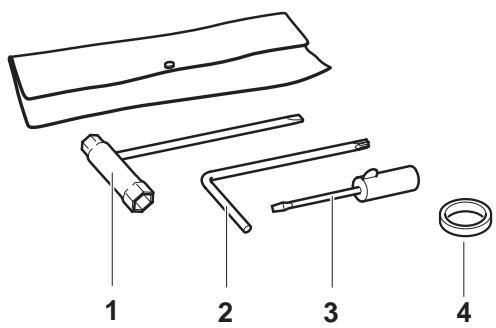
Delivery inventory

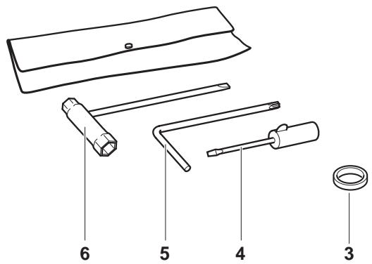
- Power Cut
- Cutting disc
- Adapter ring 0.8"/1.0" (not in the general scope of delivery. Country-specific)
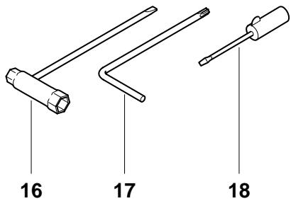
- Screwdriver (for carburetor adjustment)
- Offset screwdriver
- Universal wrench 13/19
- Instruction manual (not shown)
In case one of the parts listed should not be included in the delivery inventory, please consult your sales agent.
Symbols
You will notice the following symbols on the Power Cut and in the Instruction Manual:

Read instruction manual and follow the warning- and safety precautions!

Particular care and caution!

Forbidden!

Wear protective helmet, eye and ear protection!

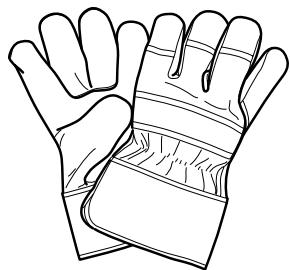
Wear protective gloves!

Wear respiratory protection!

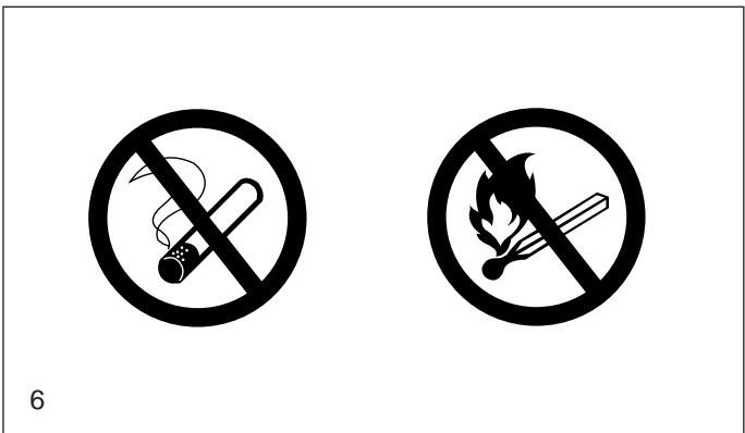
No smoking!

No open fire!

Direction of cutting wheel rotation

Warning: the max. peripheral speed of the cutting disc is 80 m/s!
Cutting disc dimensions

Never use circular saw blades!

Combination Start/Stop (I/O) switch, choke

Locked

Unlocked

Press decompression valve

Engine - manual start

Working in winter

Stop engine!
Warning!
Kickback!

Fuel and oil mixture

First aid


Recycling
SAFETY PRECAUTIONS
Intended use
Power Cut
Use the Power Cut cutoff saw outdoors only, for trimming and cutting suitable materials, using cutting discs rated for this machine.
Improper use:
Never use the cutoff saw cutting discs for grinding or sanding (using the side of the cutting disc to remove material). The disc can break! Never use the Power Cut with saw blades, cutter blades, brushes etc.
Unauthorised users:
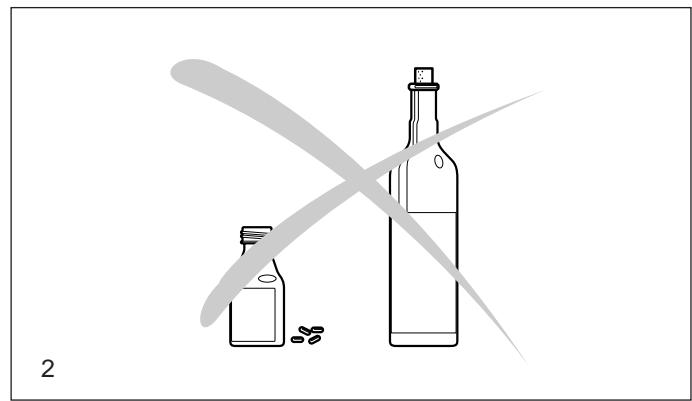
Persons unfamiliar with the Instruction Manual, children, young people, and persons under the influence of alcohol, drugs or medications must not use the Power Cut.
General precautions
- The operator MUST read this instruction manual to ensure safe operation (even if you already have experience in using cutoff saws). It is important to be familiar with the operation of this particular cutoff saw. Users insufficiently informed will endanger themselves as well as others due to improper handling.
- Let only persons who have experience in using cutoff saws work with this unit. When letting another person use the Power Cut, this instruction manual must be provided along with it.
- First-time operators should ask a specialist to instruct them in working with gasoline-powered cutoff saws.
- Children and persons under 18 years of age must not be allowed to use this Power Cut. Persons over the age of 16 years may, however, use the Power Cut for the purpose of being trained as long as they are under the supervision of a qualified trainer.
- Working with the Power Cut requires high concentration.
- Operate the Power Cut only if you are in good physical condition. If you are tired, your attention will be reduced. Be especially careful at the end of a working day. Perform all work calmly and carefully. The user has to accept liability for others.
- Never work while under the influence of alcohol, drugs, medication or other substances which may impair vision, dexterity or judgement.
- A fire extinguisher must be available in the immediate vicinity when working in easily inflammable vegetation or when it has not rained for a long time (danger of fire).
- Asbestos and other materials that can release toxins may be cut only with the necessary safety precautions and after notification of the proper authorities and under their supervision or that of a person appointed by them.
- The use of dust-reduction devices is urgently recommended (see Accessories, pressure water tank, water tank).
Protective equipment
- In order to avoid head, eye, hand or foot injuries as well as to protect your hearing the following protective equipment must be used during operation of the Power Cut:
- The kind of clothing should be appropriate, i. e. it should be tight-fitting but not be a hindrance. Clothing in which grains of material can accumulate (trousers with cuffs, jackets and trousers with wide-open pockets, etc.) must not be worn, particularly when cutting metal.
- Do not wear any jewellery or clothing that can get caught or distract from the operation of the Power Cut.
-
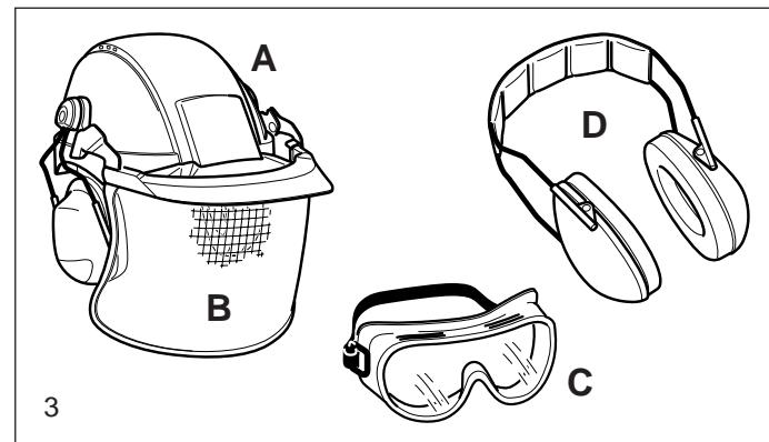
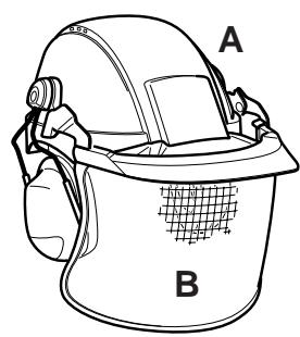
It is necessary to wear a protective helmet whenever working with the Power Cut. The protective helmet (A) is to be checked in regular intervals for damage and is to be replaced after 5 years at the latest. Use only approved protective helmets.
-
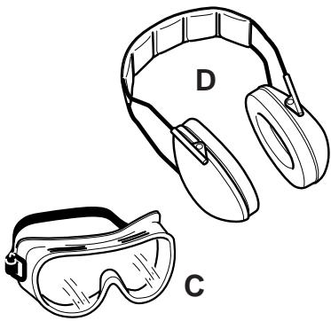
The helmet visor (B) protects the face from dust and material grains. In order to prevent injuries to eyes and face, always wear protective goggles (C) or visor when using the Power Cut.
- To prevent hearing damage, always wear suitable personal hearing protection. (ear muffs (D), ear plugs, etc.). Octave brand analysis upon request.
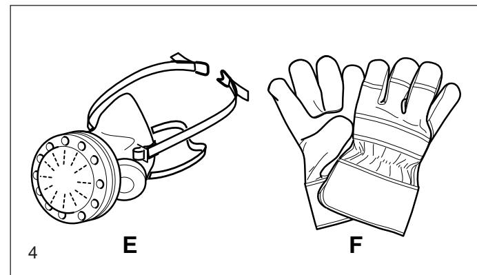
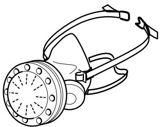
- When dry-cutting dust-producing materials such as stone or concrete, always wear approved respiratory protection (E).
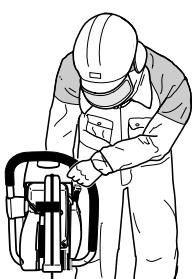
- Work gloves (F) of tough leather are part of the required work kit of the Power Cut and must always be worn when working with the Power Cut.
- The helmet visor (B) protects the face from dust and material grains. In order to prevent injuries to eyes and face, always wear protective goggles (C) or visor when using the Power Cut.
- To prevent hearing damage, always wear suitable personal hearing protection. (ear muffs (D), ear plugs, etc.). Octave brand analysis upon request.
- When dry-cutting dust-producing materials such as stone or concrete, always wear approved respiratory protection (E).
- Work gloves (F) of tough leather are part of the required work kit of the Power Cut and must always be worn when working with the Power Cut.

natural_image
Illustration of two bottles with small pills beside them, no text or symbols present
natural_image
Line drawings of four different safety gear components labeled A, B, C, and D (no text or symbols beyond labels)
natural_image
Line drawings of a gas mask and a glove, labeled E and F (no text or symbols on the devices themselves)
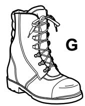
- Always wear safety shoes or boots (G) with steel toes, non-skid soles, and leg protectors when working with the Power Cut. Safety shoes equipped with a protective layer provide protection against cuts and ensure a secure footing.
- Always wear a work suit (H) of tough material with sufficient flame-retardant qualities whenever working with the cutoff saw.
Fuels / Refuelling
- Go to a safe, level place before refuelling. Never refuel while on scaffolding, on heaps of material, or in similar places!
- Switch off the engine before refuelling the Power Cut.
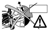
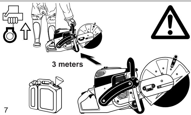
- Do not smoke or work near open fires (6).
- Let the engine cool down before refuelling.
- Fuels can contain substances similar to solvents. Eyes and skin should not come in contact with mineral oil products. Always wear protective gloves when refuelling (not the regular work gloves!). Frequently clean and change protective clothes. Do not breathe in fuel vapors. Inhalation of fuel vapours can be hazardous to your health.
- Do not spill fuel. If a spill occurs, clean off the Power Cut immediately. Fuel should not come in contact with clothes. If your clothes have come in contact with fuel, change them at once.
- Ensure that no fuel oozes into the soil (environmental protection). Use an appropriate base.
- Refuelling is not allowed in closed rooms. Fuel vapors will accumulate near the floor (explosion hazard).
- Ensure to firmly tighten the screw cap of the fuel tank.
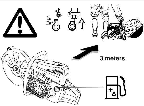
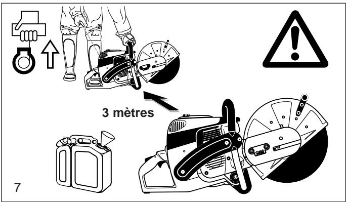
- Before starting the engine, move to a location at least 3 meters (approx. 10 feet) from where you fuelled the Power Cut (7), but not within the extended swing range of the cutting disc (direction of sparks).
- Fuel cannot be stored for an unlimited period of time. Buy only as much as will be consumed in the near future.
- When making up the gasoline/oil mixture, always put the oil in the mixing container first, and then the gasoline.
- Use only approved and marked containers for the transport and storage of fuel.
- Keep fuel away from children!
Putting into operation
- Do not work on your own. There must be someone around in case of an emergency (within shouting distance).
- Observe all anti-noise regulations when working in residential areas.
- Never use the Power Cut near inflammable materials or explosive gases! The Power Cut can create sparks leading to fire or explosion!
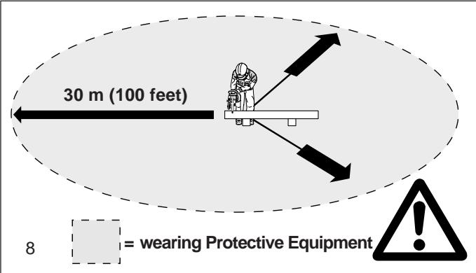
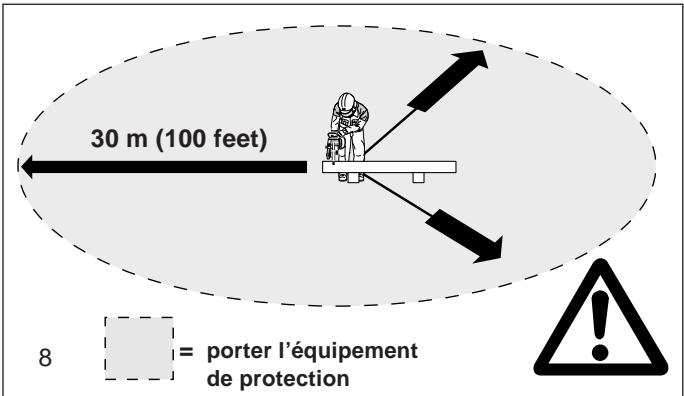
- Make sure that all persons within 30 meters (100 feet), such as other workers, are wearing protective gear (see "Protective Equipment") (8). Children and other unauthorized persons must remain more than 30 meters (100 feet) away from the working area. Keep an eye out for animals as well (9).
- Before starting work the Power Cut must be checked for perfect function and operating safety according to the prescriptions. In particular, make sure that the cutting wheel is in good condition(replace immediately if torn, damaged or bent), the cutting wheel is properly mounted, the protective hood is locked in place, the hand guard is properly mounted, the V-belt has the proper tension, the throttle moves easily and the half-throttle lock button functions properly, the grips are clean and dry, and the combination switch functions properly (Start/Stop (I/O) switch, choke).
- Start the Power Cut only after complete assembly and inspection. Never use the Power Cut when it is not completely assembled.
5

natural_image
Line drawing of a person in full-body safety gear and helmet, standing with hands on hips (no text or symbols)


6

natural_image
Illustration of a person riding a dog, no text or symbols present
natural_image
Line drawing of a worker in hard hat operating machinery (no text or symbols)


Cutoff discs
- The protection hood must always be on! Change discs only with the engine off!
- There are two basic types of cutoff discs:
- For metal (hot cutting)
- For masonry (cold cutting)
NOTE:
When using diamond cutoff discs, always make sure to observe the "direction of rotation" markings. Diamond discs should only be used for cutting masonry/brick/concrete etc.
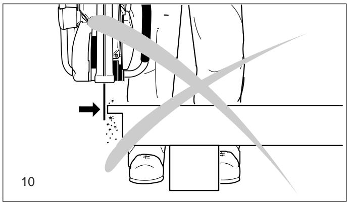
- Cutoff discs are intended only for radial loading, i.e. for cutting. Do not grind with the sides of the cutting disc! This will break the disc (10)!
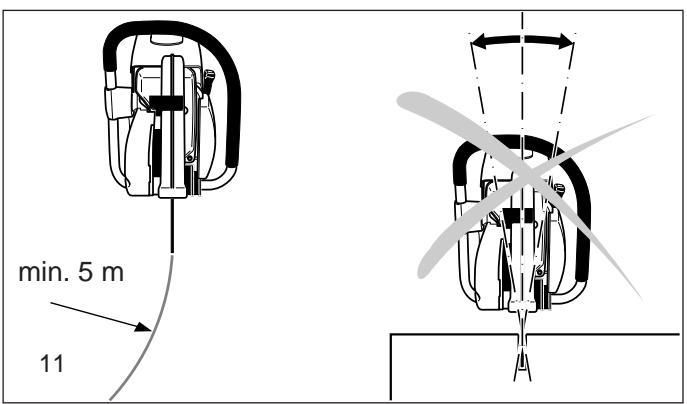
Caution!
Never change direction (turning radius less than 5 meters / 16 feet), exert lateral (sideways) pressure, or tip the Power Cut during cutting (11)!
- Use a cutting disc only for cutting the materials it is intended for. The proper type of disc must be used, for either metals or masonry.
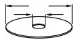
- The arbor hole of the cutting disc must be an exact fit with the arbor or shaft. If the arbor hole is larger, it must be fitted with an adapter ring (available as an accessory).
- The cutting disc must be rated for freehand cutting at up to 4370 rpm or 80 m/sec for 350 mm discs or up to 5100 rpm or 80 m/s for 300 mm discs. Use only cutting discs that comply with EN 12413, EN 13236 or der BGV D 12.
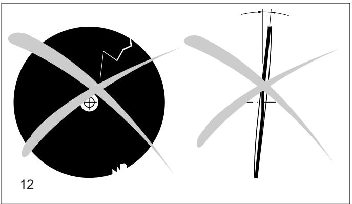
- The disc must be free of defects (12). Do not use defective cutting discs.
Always tighten the cutting disc mounting bolt to a torque of 30 Nm. Otherwise, the cutting disc can twist.
- Before starting the cutting disc, make sure you have a steady footing.
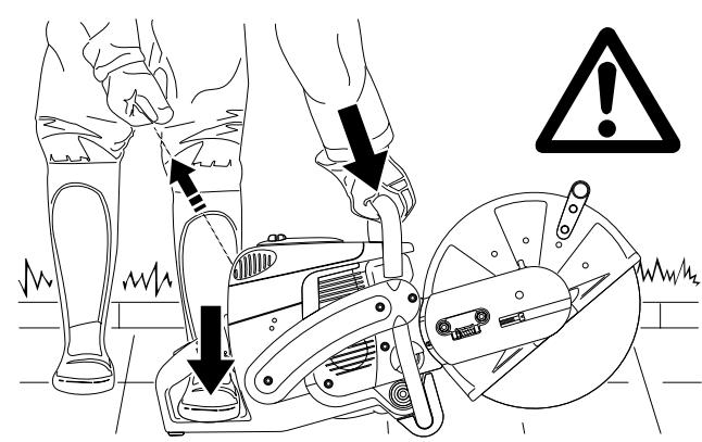
- Put the Power Cut into operation only as described in this instruction manual (13). Always place your left foot in the rear handle and grasp the other handle firmly (with thumb and fingers). Other starting methods are not allowed.
- When starting the Power Cut it must be well supported and securely held. The cutting disc must not be touching anything.
- If the cutting disc is new, test it by running it at least 60 seconds at top speed. When doing this, make sure that no persons or body parts are in the extended swing range of the disc, in case it is defective and flies apart.
- When working with the Power Cut always hold it with both hands. Take the back handle with the right hand and the tubular handle with the left hand. Hold the handles tightly with your thumbs facing your fingers.
- CAUTION: When you release the throttle lever the disc will keep spinning for a short period of time (free-wheeling effect).
- Continuously ensure that you have a safe footing.
- Hold the Power Cut such that you will not breathe in the exhaust gas. Do not work in closed rooms or in deep holes or ditches (danger of poisoning by fumes).
- Switch off the Power Cut immediately if you observe any changes in its operating behavior.
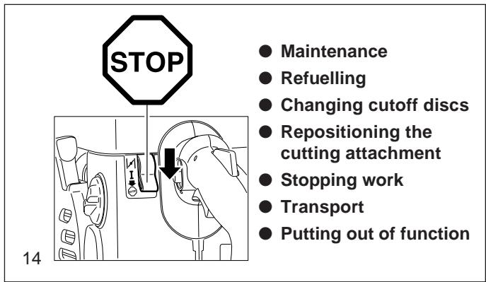
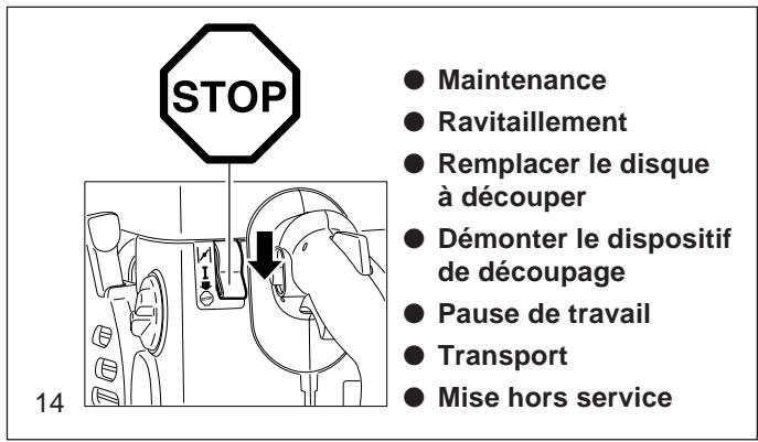
- Switch off the engine before inspecting the V-belt tension or tightening it, replacing the cutting wheel, repositioning the cutter attachment (side or middle position) or eliminating faults (14).
- Turn off the engine immediately and check the disc if you hear or feel any change in cutting behaviour.
- Turn off the Power Cut when taking a break or stopping work (14). Place the unit in such a way that the disc is not touching anything and cannot endanger anyone.
- Do not put the overheated Power Cut in dry grass or on any inflammable objects. The muffler is very hot (danger of fire).
- IMPORTANT: After wet cutting, first turn off the water feed and then let the disc run at least 30 seconds, to fling off the remaining water and prevent corrosion.
natural_image
Diagram showing a mechanical device with force arrows and cross-sectional view, no readable text or symbols present

natural_image
Two abstract diagrams showing a black circular object with intersecting lines and a gray wind turbine blade, both without any text or symbols.

Kickback and lock-in
- When working with the Power Cut there is a danger of kickback and lock-in.
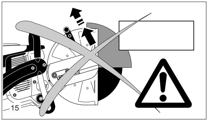
- Kickback occurs when the top of the cutting disc is used for cutting (15).
- This causes the Power Cut to be thrown back toward the user with great force and out of control. Risk of injury!
To prevent kickback, observe the following:
- Never cut with the section of the cutting disc shown in figure 15.
Be especially careful when reinserting the disc into cuts that have already been started!
- Lock-in occurs when the cut narrows (crack, or workpiece under stress).
- This causes the Power Cut to suddenly jump forward, out of control and with great force. Risk of injury!
To prevent lock-in, observe the following:
- When reinserting the disc into previous cuts, have the Power Cut running at top speed. Always cut at top speed.
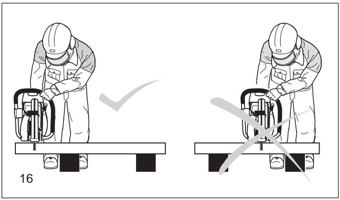
- Always support the workpiece so that the cut is under tension (16), so that the cut does not press together and jam the cutting disc as it proceeds through the material.
- When starting a cut, apply the disc to the workpiece with care. Do not just shove it into the material.
- Never cut more than one piece at a time! When cutting, make sure that no other workpiece comes into contact.
Working behavior / Method of working
- Before starting work, check the work area for any hazards (electrical wires, inflammable substances). Clearly mark the work area (for example with warning signs or by cording off the area).
- When working with the Power Cut hold it firmly by the front and rear handles. Never leave the Power Cut unattended!
- Use the Power Cut at high speed as far as possible (see "Technical Data").
- Only use the Power Cut during good light and visibility periods. Be aware of slippery or wet areas, and of ice and snow (risk of slipping).
- Never work on unstable surfaces. Make sure that there are no obstacles in the working area, risk of stumbling. Always ensure that you have a safe footing.
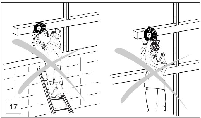
- Never cut above your shoulder height (17).
- Never stand on a ladder to cut (17).
- Never use the Power Cut while standing on scaffolding.
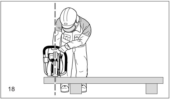
- Do not lean over too far when working. When putting down and picking up the Power Cut, do not bend over from the waist, but instead bend in the knees. Save your back!
- Guide the Power Cut in such a way that no part of your body is within the extended swing range of the disc (18).
- Use cutting discs only for the materials for which they are designed!
- Use cutting discs only for the materials for which they are designed. Do not use the Power Cut to lift up and shovel away pieces of material and other objects.
Important! Before cutting, remove all foreign objects, such as rocks, gravel, nails etc. from the cutting area. Otherwise, such objects can be flung away by the disc with great speed. Injury hazard!
- When cutting workpieces down to length use a firm support. If necessary, secure the workpiece from slipping, but do not steady it with your foot or allow another person to hold it.
- When cutting round items, always secure them against rotation.
- When guiding the Power Cut by hand, use the side mounting position of the cutter attachment only when actually necessary. Otherwise, always use the central position. This gives the unit a better balance, for reduced operator fatigue.


natural_image
Two-panel illustration showing workers on a ladder and a welding helmet, both without any text or symbols.

natural_image
Illustration of a worker using a power tool on a bench, no text or symbols present
IMPORTANT!
Always wear approved respiratory protection!
Materials that can release toxic substances may be cut only after notifying the proper authorities and under their supervision or that of a person appointed by them.
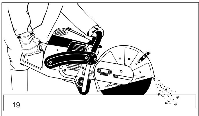
CAUTION!
The rapid rotation of the cutting disc heats metal and melts it at the point of contact. Swing the guard as far down as possible (19) in order to direct the stream of sparks forward, away from the operator (fire hazard).
- Determine the cut line, mark the cut and apply the disc to the material at moderate speed, to cut a guide groove before going to top speed and applying more pressure to the Power Cut.
- Keep the disc straight and vertical. Do not tip it, as this can break it.
- The best way to get a good, clean cut is to pull or move the Power Cut back and forth. Do not simply press the disc into the material.
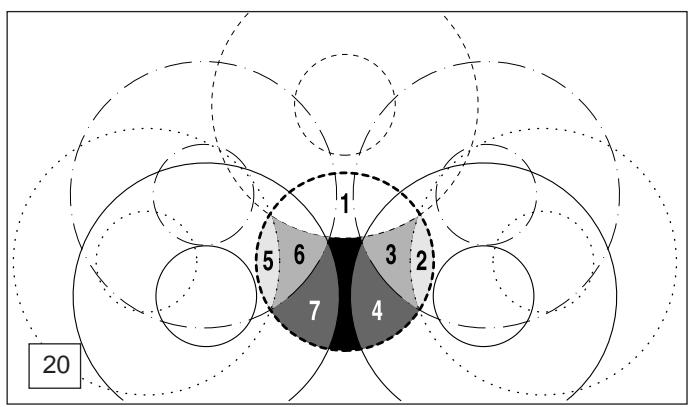
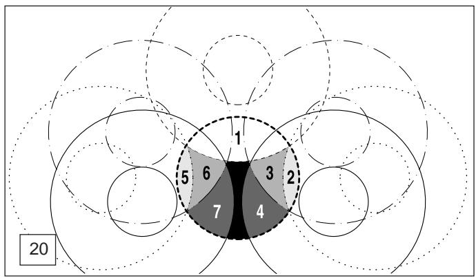
- Thick round stock is best cut in stages (20).
- Thin tubing and pipes can be cut with a simple downward cut.
- Cut large-diameter pipes as for round stock. To prevent tipping and for better control, do not let the disc sink too deeply into the material. Instead, always cut shallow around the whole piece.
- Worn discs have a smaller diameter than new discs, so that at the same engine speed they have a lower effective circumferential speed and therefore do not cut as well.
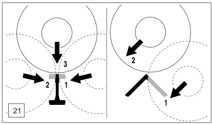
- Cut I-beams and L-bars in steps; see Figure 21.
- Cut bands and plates like pipes: along the wide side with a long cut.
- When cutting material under stress (supported material or material in structures), always make a notch in the thrust (pressure) side, and then cut from the tension side, so that the disc does not lock in. Secure cutoff material from falling!
CAUTION!
If there is a chance that the material is under stress, be prepared for it to kick back. Make sure you can get out of the way if you have to!
Be particularly careful in scrap-metal yards, junkyards, at accident sites, and with haphazard piles of material. Precariously balanced pieces or pieces under stress can act in unpredictable ways, and may slide, jump out, or burst. Secure cutoff material from falling! Always exercise extreme caution and use only equipment that is in perfect working order.
Observe the accident-prevention rules and regulations of your employer and/or insurance organization.
Cutting masonry and concrete
IMPORTANT!
Always wear approved respiratory protection!
Asbestos and other materials that can release toxic substances may be cut only after notifying the proper authorities and under their supervision or that of a person appointed by them. When cutting prestressed and reinforced concrete piles, follow the instructions and standards of the responsible authorities or the builder of the structural member. Reinforcement rods must be cut in the prescribed sequence and in accordance with applicable safety regulations.
NOTE:
Mortar, stone, and concrete develop large quantities of dust during cutting. To increase the lifetime of the cutting disc (by cooling), to improve visibility, and to avoid excessive dust creation, we strongly recommend wet cutting instead of dry cutting.
natural_image
Illustration of a person using a cutting tool on a workbench, with sparks flying (no text or symbols)
geo
| Region | Value |
|--------|-------|
| 1 | 1 |
| 2 | 2 |
| 3 | 3 |
| 4 | 4 |
| 5 | 5 |
| 6 | 6 |
| 7 | 7 |
flowchart
graph TD
    A["Left Diagram"] --> B["Component 1"]
    B --> C["Component 2"]
    C --> D["Component 3"]
    D --> E["Bottom Left"]
    F["Right Diagram"] --> G["Component 1"]
    G --> H["Component 2"]
    H --> I["Bottom Right"]
    style A fill:#f9f,stroke:#333
    style F fill:#f9f,stroke:#333
    style G fill:#f9f,stroke:#333
In wet cutting, the disc is wetted at an equal rate on both sides by a trickle of water. MAKITA offers the right accessories for all wet cutting applications (see also "SPECIAL ACCESSORIES").
- Remove foreign objects such as sand, stones and nails found within the working area. Caution: Watch out for electric wires and cables!
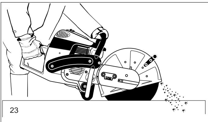
The rapid rotation of the cutting disc at the point of contact throws fragments out of the cut groove at high speed. For your safety, swing the protection hood down as far as possible (23), so that material fragments are thrown forward, away from the operator.
- Mark the cut, and then make a groove about 5 mm (just under 1/5") along the entire length of the planned cut. This groove will then guide the Power Cut accurately guring the actual cutoff.
NOTE:
For long, straight cuts we recommend using a trolley (24, see also "SPECIAL ACCESSORIES"). This makes it much easier to guide the unit straight.
- Perform the cut with a steady back-and-forth motion.
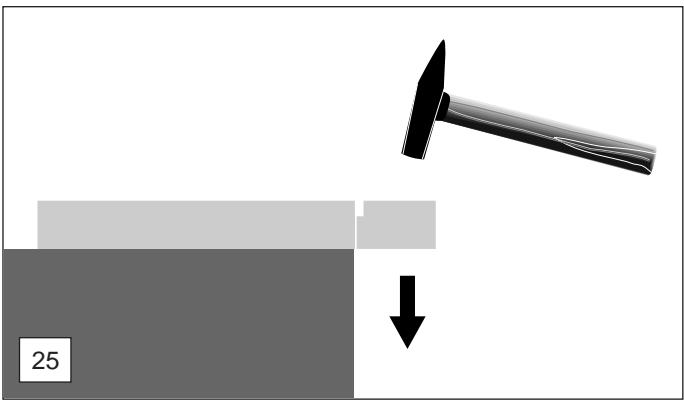
- When cutting slabs to size, you need not cut through the entire material thickness (creating unnecessary dust). Instead, simply make a shallow groove, and then knock off the excess material cleanly on a flat surface (25).
CAREFUL!
When cutting into lengths, cutting through material, making cutouts, etc., always make sure to plan the direction and sequence of cuts in such a way that the disc does not get jammed by the cut-off piece, and that no persons can be injured by falling pieces.
Transport and storage
- Always turn off the Power Cut when transporting it or moving it from place to place on a site (26).
- Never carry or move the unit with the engine on or the disc moving!
- Carry the unit only by the tubular (middle) handle with the cutting disc pointing behind you (26). Avoid touching the exhaust muffler (burn hazard!)
- When moving the Power Cut over longer distances, use a wheelbarrow or wagon.
- When transporting the Power Cut in a vehicle, make sure it is securely positioned in such a way that no fuel can leak out. Always remove the cutting disc before transporting the unit in a vehicle.
- The Power Cut should be stored safely in a dry place. It must not be left outdoors! Always dismount the cutting disc before storage. Keep the Power Cut away from children.
- Before long-term storage and before shipping the Power Cut, follow the instructions in the chapter on "Periodic care and maintenance". ALWAYS empty the fuel tank and run the carburetor dry.
- When putting cutting discs in storage, be careful to:
- Clean and dry them well.
- Store them lying down flat.
- Avoid dampness, freezing temperatures, direct sunshine, high temperatures and temperature fluctuations, as these can cause breakage and splintering.
- Always check new cutting discs or cutting discs that have been in storage to make sure that they are free of defects and before the first cut test-run the tool at top speed for at least 60 seconds. Keep body parts and people well away out of range of the direction of the cutting disc during this test.
natural_image
Illustration of a person using a cutting tool on a workbench, with sparks flying (no text or symbols)

natural_image
Technical line drawing of a mechanical power tool with a cylindrical component and wheels, no text or symbols present
natural_image
Diagram showing a hammer striking a block with a downward arrow, no text or symbols present

Maintenance
- Before performing maintenance work switch off the Power Cut (27) and pull out the plug cap.
- Always check the Power Cut before using it to make sure that it is in good working order. In particular, make sure that the cutting disc is properly mounted. Make sure that the cutting wheel is undamaged and suitable for the job it will be used for.
- Operate the Power Cut only at a low noise and emission level. For this ensure the carburetor is adjusted correctly.
- Clean the Power Cut regularly.
- Check the fuel tank cap regularly for good sealing.
Observe the accident prevention instructions issued by trade associations and insurance companies. NEVER make any modifications to the Power Cut! You will only be putting your own safety at risk!
Perform only the maintenance and repair works described in the instruction manual. All other work must be carried out by MAKITA Service.
Use only original MAKITA spares and accessories.
The use of non-MAKITA spares, accessories, or cutting discs increases the risk of accident. We cannot accept any responsibility for accidents or damage occurring in association with the use of cutting discs or accessories other than original MAKITA.
First aid
For the event of a possible accident, please make sure that a first aid kit is always immediately available close by. Immediately replace any items used from the first aid box.
When calling for help, give the following information:
- Place of the accident
- What happened
- Number of injured people
- Kind of injuries
- Your name!
NOTE
Individuals with poor circulation who are exposed to excessive vibration may experience injury to blood vessels or the nervous system.
Vibration may cause the following symptoms to occur in the fingers, hands or wrists: "Falling asleep" (numbness), tingling, pain, stabbing sensation, alteration of skin colour or of the skin. If any of these symptoms occur, see a physician!


27

SERVICE
28

natural_image
Simple black-and-white cross symbol on white background (no text or symbols)
29
Technical data
| Technical data | DPC6410 | DPC6411 | DPC7310 | DPC7311 |
| Displacement | cu in (cm3) | 3.9 (64) | 4.5 (73) |
| Bore | in (mm) | 1.85 (47) | 1.97 (50) |
| Stroke | in (mm) | 1.46 (37) | 1.46 (37) |
| Max. power | hp (kW) | 4.4 (3.2) | 5.6 (4.2) |
| Max. torque | Nm | 4.0 | 5.0 |
| Idling speed | 1/min | 2,500 | 2,500 |
| Clutch engagement speed | 1/min | 3,800 | 3,800 |
| Engine speed limitation | 1/min | 9,350 | 9,350 |
| Max. spindle speed | 1/min | 4,300 | 4,300 |
| Sound pressure level at the operators ear 1) | dB (A) | 97 | 104 |
| Sound pressure level at the bystander's position (50 ft)1) | dB (A) | 84 | 86 |
| Vibration acceleration ah,w per EN 1454-Tubular handle (idle/rated spindle speed)- Rear handle (idle/rated spindle speed) | m/s2 | 6 / 5 | 7 / 6 |
| m/s2 | 8 / 6 | 8 / 7 |
| Carburetor (diaphragm carburetor) | Type | TILLOTSON HS-273 A |
| Ignition system (with speed limitation) | Type | electronic |
| Spark plug | Type | NGK BPMR 7A / BOSCH WSR 6F / CHAMPION RCJ 6Y |
| Electrode gap | in (mm) | .020 (0.5) | .020 (0.5) |
| Fuel consumption at max. load per ISO 8893 | kg/h | 1.65 | 2.1 |
| Specific consumption at max. load per ISO 8893 | g/kWh | 500 | 500 |
| Fuel tank capacity | fl oz (l) | 37 (1.1) | 37 (1.1) |
| Mixture ratio (fuel/two-stroke oil)- when using MAKITA HP 100 high-performance oil | | 100:1 | 100:1 |
| - when using MAKITA oil | | 50:1 | 50:1 |
| Cutting disc for 80 m/sec. 2) | in | 12" / 0.8" / 0.2" 3) | 14" / 0.8" / 0.2" 3) | 12" / 0.8" / 0.2" 3) | 14" / 0.8" / 0.2" 3) |
| Cutting disc for 80 m/sec. 2) 4) | in | | 14" / 1" / 0.2" 3) | | 14" / 1" / 0.2" 3) |
| Arbor diameter | in | 0.8" | 0.8" / 1.0" | 0.8" | 0.8" / 1.0" |
| V-belt (MAKITA no.) | | 965 300 470 | 965 300 470 |
| Overall weight (tanks empty, without cutting disc) | lb | 21.38 | 21.82 | 21.6 | 22.04 |
1) According to UL-test requirement under full load (cutting concrete).
^2) Circumference speed at max. engine speed
^3) Outside diameter / arbor hole / thickness
4) Country-specific
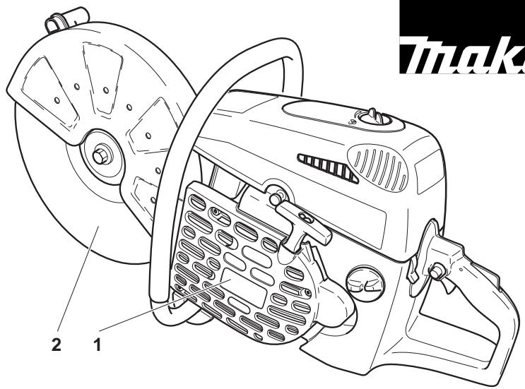
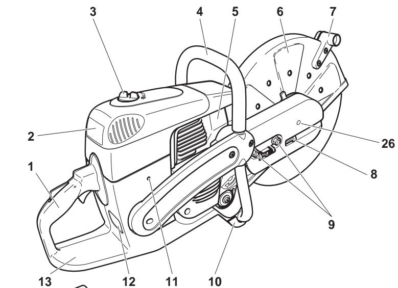
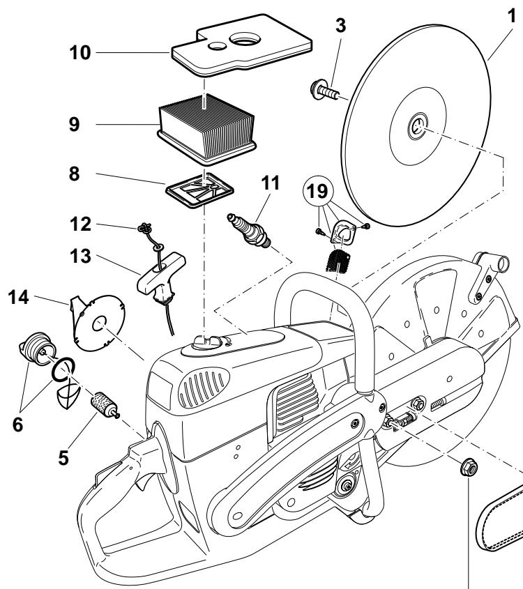
Denomination of components
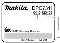
Identification plate (12)
Indicate when ordering spare parts
Serial number
Year of manufacture
1 Handle
2 Filter cover for air filter and spark plug cap
3 Cover lock
4 Tubular handle
5 Muffler
6 Protection hood
7 Grip
8 V-belt tension adjusting screw
9 Retaining nuts
10 Stand
11 Carburetor adjustment opening
12 Identification plate
13 Fuel tank with handle
14 Decompression valve
15 Starter grip
16 Air intake
17 Combination Start/Stop (I/O) switch, choke
18 Stop knob for halfway throttle
19 Safety locking button
20 Throttle lever
21 Tank cap (fuel)
22 Starter housing with starter
23 Cutting disc
24 Disc bolt
25 Spring washer
26 Hold opening


A
Always turn off the engine and pull off the spark plug cap before doing any work on the Power Cut! Always wear protective gloves!
CAUTION:
Start the Power Cut only after complete assembly and inspection.
B
For the following work, use the assembly tools included with delivery:
- 13/19 AF combination wrench
- Allen key
- Carburetor adjustment screwdriver
- Adapter ring (not in the general delivery inventory)
Place the Power Cut on a stable surface and carry out the following assembly steps:
C
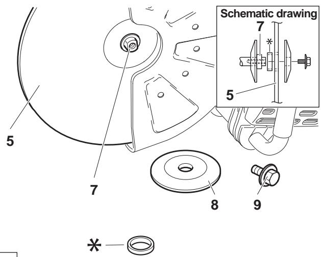
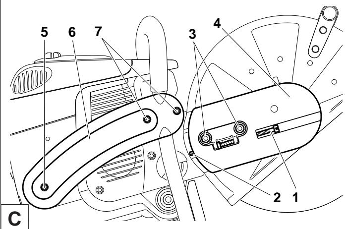
Mounting the cutting disc
Inspect the disc for damage.
See SAFETY INSTRUCTIONS, Page 7.

Unscrew screw (9) and remove the spring washer (8).
Place the cutting disc (5) on the arbour (7).
Hinweis: The arbor hole of the cutting disc must be an exact fit with the arbor or shaft. If the arbor hole is larger, it must be fitted with an adapter ring (*).

Make sure the cutting disc is installed so it turns in the right direction, if a direction is marked on the disc.
D
Place the spring washer (8) on the arbour and insert the screw (C/9) and tighten by hand.
Turn the disc slowly until the stop hole of the V-belt pulley is visible in the cutting arm cover (10).
Insert the Allen key (2) as far as it will go. The shaft is now blocked.
Tighten the screw with the combination wrench (1)
NOTE: Tighten the screw firmly (30 ± 2 Nm), as otherwise the cutting wheel may slip during cutting.


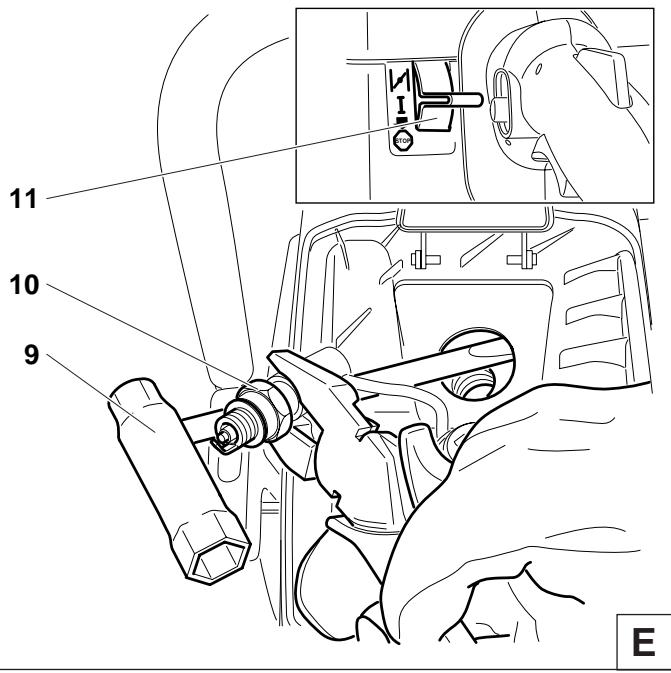
Tightening the V-belt / Checking V-belt tension
IMPORTANT:
Exact V-belt tension is essential for maximum cutting performance with minimum fuel consumption. Improper V-belt tension will result in premature wear to the V-belt and V-belt wheel or damage to the clutch bearing.
If the Power Cut is new or the V-belt has been replaced, retighten the V-belt after the first hour of operation!
E
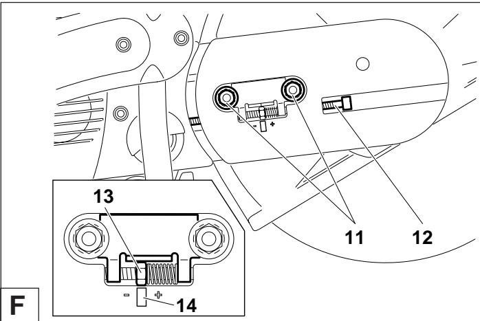
NOTE: The two fastening nuts (11) must be loosened before tightening the V-belt or checking the tension.
To increase the belt tension, turn the tightening screw (12) to the right (clockwise) with the combination wrench included with the Power Cut.
The belt tension is correctly adjusted when the nut (13) is centred on the mark (14).

IMPORTANT:
After tightening/inspection, make certain to tighten the fastening nuts (11) (30 ± 2 Nm).
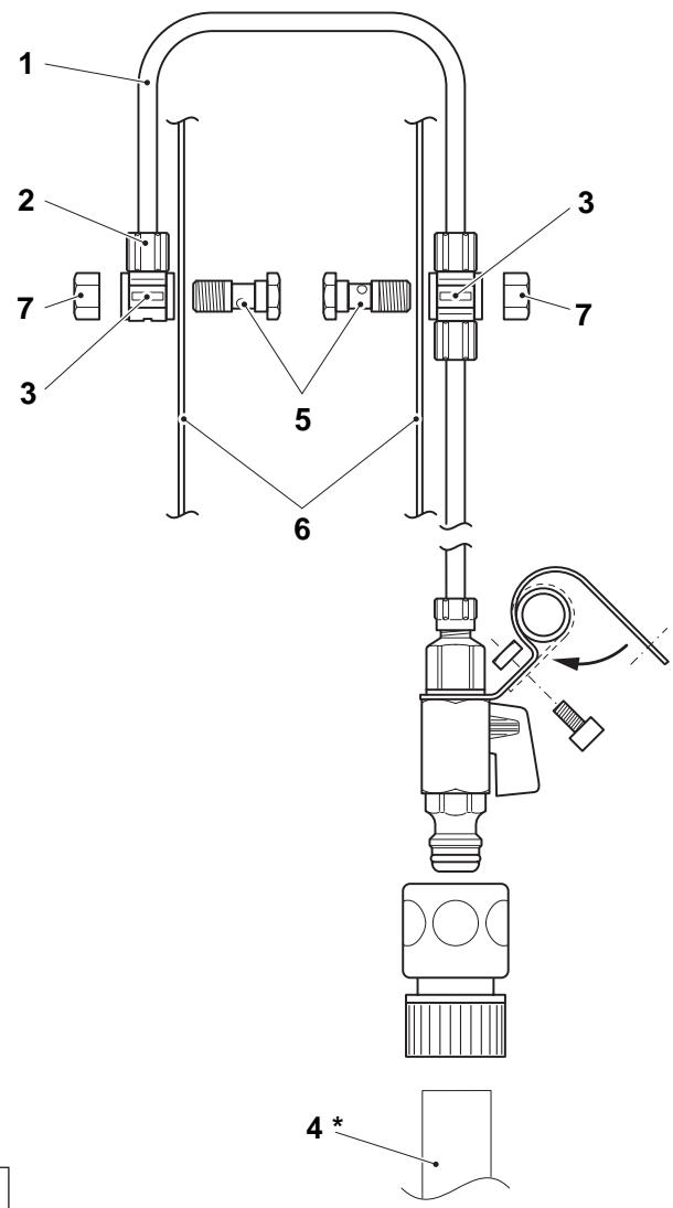
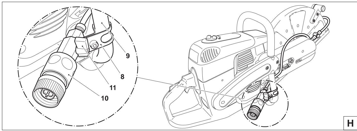
Installing the pressure water system
Not in the general scope of delivery. Country-specific!

CAUTION: Before doing any work on the Power Cut, always switch off the engine and disconnect the spark plug cap!
NOTE: When using a protective hood for a maximum disk diameter of 300 mm (12"), always shorten hose (1) to 180 mm (7").
To do this unscrew sleeve (2) and carefully pull tube (1) off coupling (3) and cut to 180 mm. Then push the tube end back over the coupling and tighten the sleeve all the way.
- Install the water connection as shown in Figure H. Push clamp (H/8) around the front grip (H/9) and fasten with the bolt and square nut.
- Pull the quick-release coupling (H/10) from the water connection and connect it to the 1/2" supply line (4).
- Remove the cutting disk (see instruction manual).
- Tube routing with the cutting assembly in the middle position, see Fig. H.
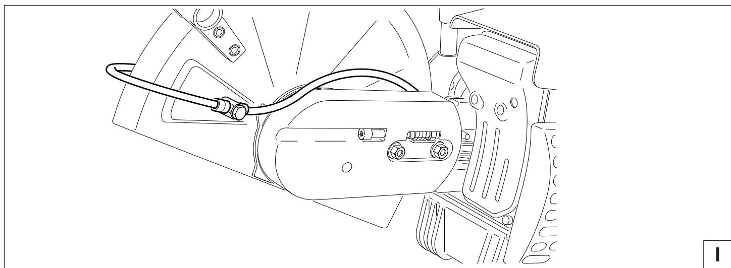
- Tube routing with the cutting assembly in the outside position, see Fig. I.
- Insert the nozzles (5) through the protective hood (6) from the inside and put on couplings (3). Screw on and tighten the coupling caps (7).
IMPORTANT:
To avoid bending the tubes, be sure to position the couplings (3) in accordance with Fig. H or I as appropriate.
- Install the cutting disc (see instruction manual).
- Connect the quick-release coupling (H/10) to the supply tube.
NOTE:
The water flow rate can be precisely adjusted with valve (H/11).
G
natural_image
Technical line drawing of a mechanical assembly with hoses and components (no text or symbols)
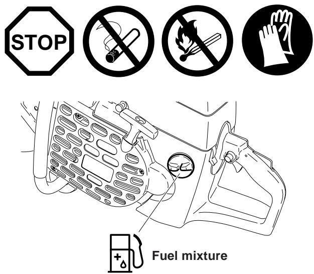
Fuels
Caution:
The Power Cut uses mineral-oil products (gasoline and oil). Be especially careful when handling gasoline.
Do not smoke. Do not allow gasoline to come near flames, sparks or fire (explosion hazard).
Fuel mixture
The Power Cut is powered by a high-performance two-stroke engine. It runs on a mixture of gasoline and two-stroke engine oil.
The engine is designed for unleaded regular gasoline with a min. octane value of 91 ROZ. In case no such fuel is available, you can use fuel with a higher octane value. This will not affect the engine.
In order to obtain an optimum engine output and to protect your health and the environment use unleaded fuel only. Gasoline which contains alcohol should not used in MAKITA products.
To lubricate the engine, use a high-performance two-stroke engine oil (quality grade JASO FC or ISO EGD), which is added to the fuel. The engine is designed for the use of MAKITA HP 100 high-performance two-stroke engine oil at a mixture ratio of only 100:1 to protect the environment. In addition, this ensures a long service life and reliable operation with minimum exhaust emissions.

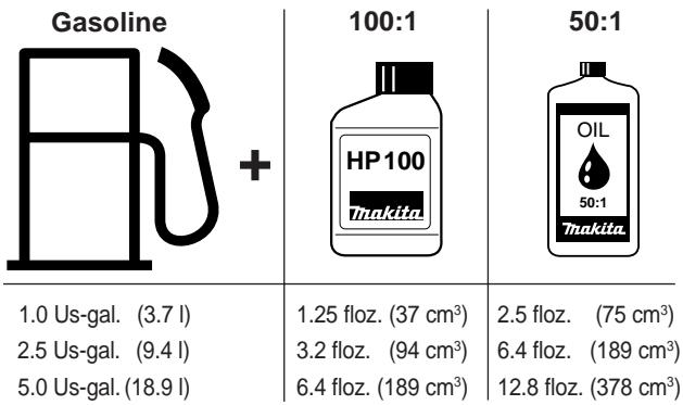
other
| Gasoline | 100:1 | 50:1 |
| -------- | ----- | ---- |
| 1.0 Us-gal. (3.7 l) | 1.25 floz. (37 cm³) | 2.5 floz. (75 cm³) |
| 2.5 Us-gal. (9.4 l) | 3.2 floz. (94 cm³) | 6.4 floz. (189 cm³) |
| 5.0 Us-gal. (18.9 l) | 6.4 floz. (189 cm³) | 12.8 floz. (378 cm³) |
The correct mixture ratio:
100:1 When using MAKITA HP 100 high-performance two-stroke engine oil, i. e. 100 parts gasoline to 1 part oil.
50:1 When using MAKITA high-performance two-stroke engine oil, i. e. 50 parts gasoline to 1 part oil.
MAKITA HP 100 high-performance two-stroke engine oil is available in the following sizes to suit your individual requirements:
0,5 l order number 980 008 609
MAKITA high-performance two-stroke engine oil (50:1) is available in the following sizes to suit your individual requirements:
100 ml order number 980 008 606
1 | order number 980 008 607
NOTE: For preparing the fuel-oil mixture first mix the entire oil quantity with half of the fuel required, then add the remaining fuel. Shake the finished mixture thoroughly before pouring it into the Power Cut tank.
Caution: Open the tank cap carefully, as pressure might have built up inside!
It is not wise to add more engine oil than specified to ensure safe operation. This will only result in a higher production of combustion residues which will pollute the environment and clog the exhaust channel in the cylinder as well as the muffler. In addition, fuel consumption will rise and performance will decrease.
The Storage of Fuel
Fuels have a limited storage life. Fuel and fuel mixtures age. Therefore fuel and fuel mixtures, which have been stored for too long, can cause starting problems. Purchase only that amount of fuel, which will be consumed over the next few months.
Store fuel safely in a dry place in approved containers only.

Mineral oil products degrease your skin. If your skin comes in contact with these substances repeatedly and for an extended period of time, it will dry out. Various skin deseases may result. In addition, allergic reactions are known to occur. Eyes can be irritated by contact with oil. If oil comes into your eyes, immediately wash them with clear water.
If your eyes are still irritated, see a doctor immediately!
A
Refuelling
IMPORTANT:
FOLLOW THE SAFETY PRECAUTIONS!
Be careful and cautious when handling fuels.
The engine must be turned off and cooled down!
Carefully clean the area around the fuel-tank filler neck to keep dirt from getting in the tank.
Place the unit on its side on an even surface.
Unscrew the tank cap and fill tank with fuel mixture. Take care to avoid spilling.
Screw the tank cap back on hand-tight.
Clean screw cap and tank after refuelling. Never start or operate the Power Cut in the same place as it was fuelled!
If fuel gets on your clothing, change clothes immediately.
B
Starting the engine


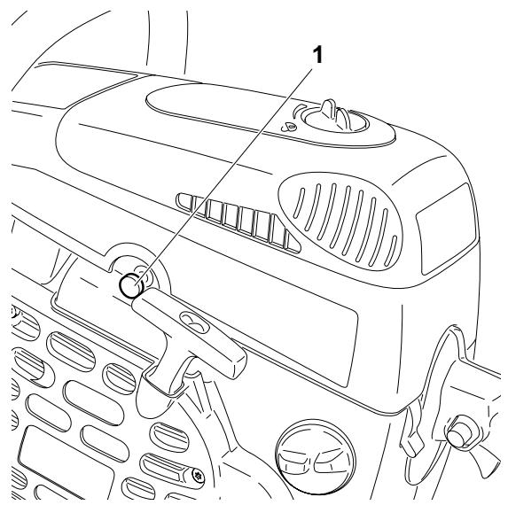
This model is fitted with a semiautomatic decompression valve (1) to make starting easier. Depressing it reduces the force needed for compression, so little force is needed to accelerate the engine to its starting speed.
The high pressure in the combustion chamber after the first ignition automatically closes the decompression valve (button pops out).
natural_image
Line drawing of a car interior showing dashboard, air vent, and control knobs (no text or symbols)
C
CAUTION:
Observe the SAFETY INSTRUCTIONS on page 5 and 6!
Start the Power Cut only after complete assembly and inspection!
Move at least 10 feet (3m) away from the place where you fuelled the Power Cut.
Make sure you have a good footing, and place the Power Cut on the ground in such a way that the cutting disc is not touching anything.
D
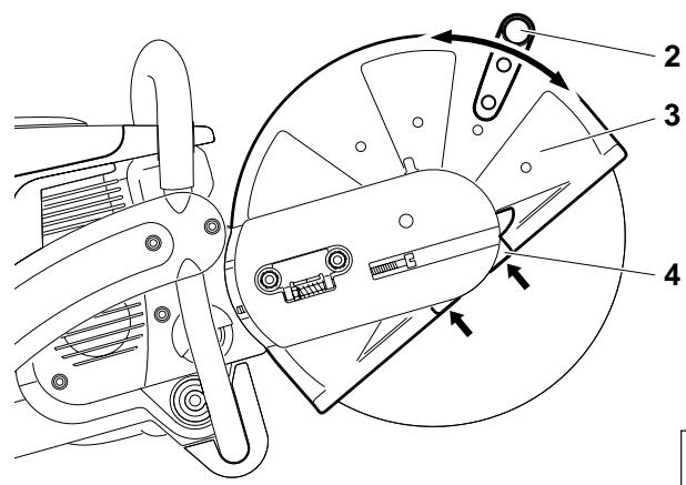
Move the protective hood (3) into the proper position for the work you intend to do (see illustration).
Grasp the grip (2). The hood (3) can swing in both ways within its range of motion.
Caution:
Always make sure that the straight outer edge of the impact plate (4) and the edge of the hood are parallel (see arrows).
If this is not the case, take the tool to a service center.
E
Cold-starting
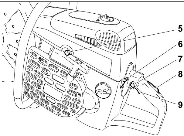
Move the combination switch (6) up (choke position).
Grasp handle (hand pressure actuates the grip throttle lever lock (8)).
Push the throttle (9) in all the way and hold it.
Press the throttle lock (7) and release the throttle (9) (the throttle lock will hold the throttle at half-throttle position).
NOTE: If the Power Cut is in a trolley, bring the control lever to the third or fourth detent.
Depress decompression valve (5).
F
G
Grasp the tubular handle firmly with one hand and press the Power Cut against the ground.
Place the tip of your left foot in the rear handle.
Pull the starter cable strong and rapidly until you hear the first audible ignition.
CAUTION: Do not pull out the starter cable more than approx. 20" (50 cm), and lead it back by hand.
Depress decompression valve (F/5) again.
Put the combination switch (F/6) in position "I".
Keep pulling the starter cable until the engine catches.
As soon as the engine is running, press the throttle (F/9) to release the half-throttle lock (F/7), allowing the engine to idle.
Warm-starting
As described under "Cold starting", except without putting the combination switch (F/6) in choke position.
H
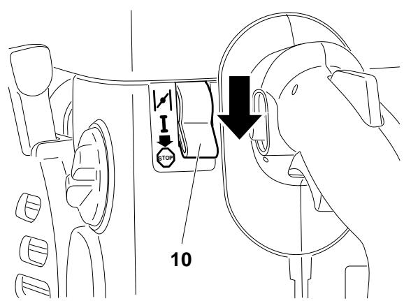
Stopping the engine
Push the combination switch (1) down to position

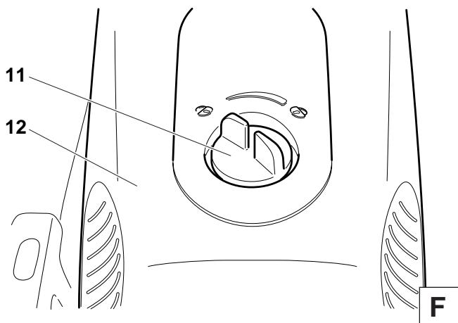
Adjusting the carburetor

NOTE: The grinding parts are equipped with an electronic ignition to limit the speed. The carburetor also has a fixed jet which cannot be adjusted.
At the factory the idling speed has been set to approx. 2,500 1/min., but the running-in process of a new engine may require slight readjustment of the idling speed.
A
For correct adjustment of the idling speed the following steps must be carried out:
Start the engine and run it until it is warm (about 3 - 5 minutes).


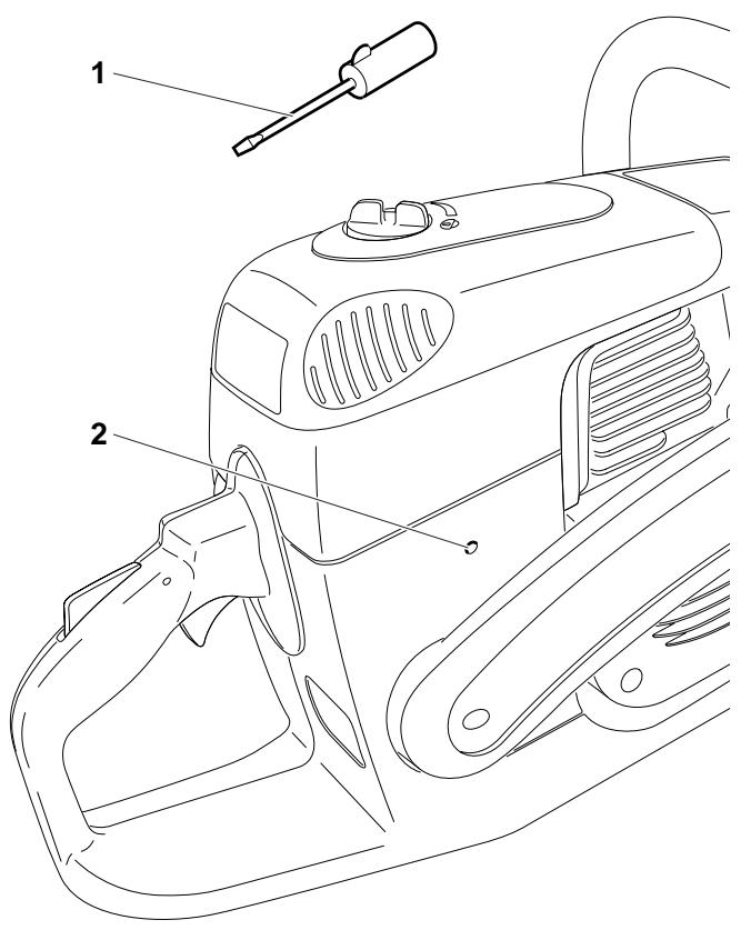
B
Adjust the carburetor with the screwdriver (1, Order No. 944 340 001) included with the Power Cut. It has a lug that helps with adjustment.
Readjust the idling speed.
If the cut-off disc is still turning when the engine is running, unscrew the adjusting screw of the throttle valve (2) until the cut-off disc is no longer turning. When the engine is left running at idling speed, loosen the screw a little.
Switch off the engine

C

A
MAINTENANCE
CAUTION:
Before doing any work on the Power Cut turn off the engine, remove the cutting disc, pull the plug cap off the spark plug and wear protective gloves!
CAUTION:
Start the Power Cut only after complete assembly and inspection.

SERVICE
IMPORTANT:
Because many of the parts and assemblies not mentioned in this Instruction Manual are vital to the safety of the unit, and because all parts are subject to a certain amount of wear and tear, it is important for your own safety that you have the unit checked and maintained regularly by a MAKITA service center.
IMPORTANT:

If the cutting wheel breaks during cutting, the Power Cut must be repaired by a MAKITA service center before being used again!
B
Changing the V-belt
Loosen nuts (3).
Loosen the tightening screw (1) (counter-clockwise) until the end of the screw (2) is visible in the gap.
Unscrew the nuts (3) and remove the cover (4).
Remove the screws (5) and (7) and remove the side piece (6).
NOTE:

Screw (5) is longer than screws (7). Make sure to put them back in the right places during reassembly!
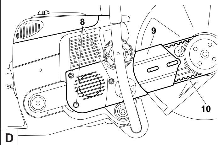
Unscrew the screws (8) and remove the crankcase housing cover (9).
Remove the old belt (10) or belt pieces.
Clean out the inside of the drive arm with a brush.
Put in a new V-belt.
NOTE:
Reassemble the crankcase housing cover (9), side piece (C/6) and cover (C/4) in the reverse order.
To tighten the V-belt see "Tightening the V-belt / Checking V-belt tension".
Cleaning the protection hood
Over time, the inside of the protective hood can become caked with material residue (especially from wet cutting), which if allowed to accumulate can hinder the free rotation of the cutting disc. For this reason the hood must be cleaned out from time to time.
Take off the cutting wheel with spring washer and remove the accumulated material from inside the hood with a strip of wood or similar implement.
Clean the shaft and all removed parts.


NOTE: To install the cutting wheel see "Mounting the cutting wheel".
E
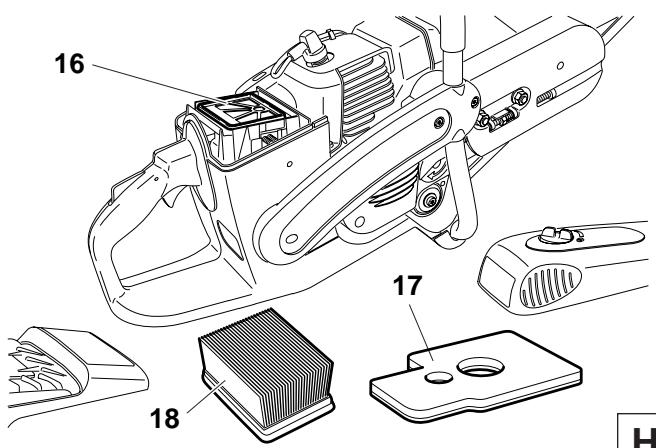
Cleaning / changing the air filter


Turn the cover lock (11) to the "Unlocked ⏻" position and carefully remove the filter cover (12).
There are two O-rings (G/15) between the filter cover (12) and the air filter hood (G/14).
Remove screws (13) and take off the cover (14).
Clean the O-ring (15) with a brush and inspect for damage.
G
Take the pre-filter (foam, 17) out of the filter cover.
Pull the air filter insert (paper cartridge, 18) out of the cover.
Remove the inner filter (16) from the intake opening.
Note:
Do not allow dirt to get into the carburetor!
Switch the combination switch to "Choke" or cover the carburetor with a clean cloth.
H
CAUTION:

Never clean out the air filter with compressed air! Do not clean the pre-filter and inner filter with fual.
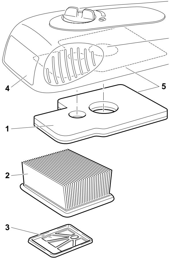
Pre-filter (foam) and inner filter
If the pre-filter (1) and inner filter (3) are dirty, wash them out in lukewarm water with regular dishwashing liquid.
Dry pre-filter and inner filter thoroughly.
NOTE: The pre-filter needs cleaning at least daily, or more often if the Power Cut is used in very dusty conditions. If cleaning on-site is not possible, keep a replacement pre-filter on hand.
Replace the pre-filter after every 20 operating hours at the latest.
To improve filtration, wet the pre-filter with air filter oil. Before doing this, carefully clean the pre-filter with air filter cleaner. Be sure to follow manufacturer's instructions.
When inserting the pre-filter in the filter cover, align it with the cover opening and press it into the cover (5).
Filter insert (paper cartridge)
The air filter insert (2) filters the intake air through a very fine paper fan filter system, so it must never be washed. Clean the filter insert once weekly.
To do so, open it slightly and carefully tap it out against a clean surface.
Replace the filter insert every 100 operating hours. Replace it immediately if there is loss in power, loss in speed, or smoke develops in the exhaust.
Before installing the filter system, check the intake opening for any dirt particles that may have fallen in. If so, remove them.
CAUTION:
If the air filter becomes damaged, replace immediately!
Pieces of cloth or large dirt particles can destroy the engine!
A

Replacing the spark plug


CAUTION:
Do not touch the spark plug or plug cap if the engine is running (high voltage).
Switch off the engine before starting any maintenance work.
A hot engine can cause burns. Wear protective gloves!
The spark plug must be replaced in case of damage to the insulator, electrode erosion (burn) or if the electrodes are very dirty or oily.
Turn the cover lock (6) to the "Unlocked ⏻" position and carefully remove the filter cover (7).
Flip up the spark-plug cover (8).
Pull the plug cap (8) off the spark plug. Use only the combination wrench supplied with the saw to remove the spark plug.
Electrode gap
The electrode gap must be .020" (0.5 mm).
B
Checking the ignition spark
Insert the combination wrench (9) between the hood and cylinder only as shown.
CAUTION!
Do not insert the combination tool into the spark plug hole, but make contact only with the cylinder (otherwise you may damage the engine).
Using insulated pliers, hold the spark plug (10) (unscrewed but with the plug cap on) against the combination tool (away from the spark plug hole!).
Switch the combination switch (11) to "I".
Pull the starter cable hard.
If the function is correct, an ignition spark must be visible near the electrodes.
CAUTION: Use only BOSCH WSR 6F spark plug, CHAMPION RCJ-6Y or NGK BPMR 7A.
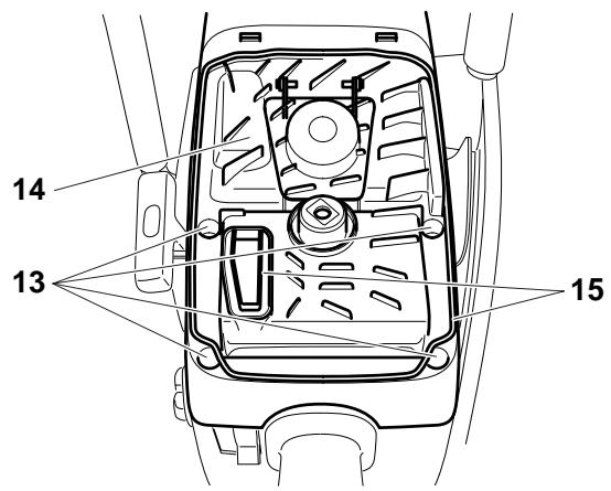
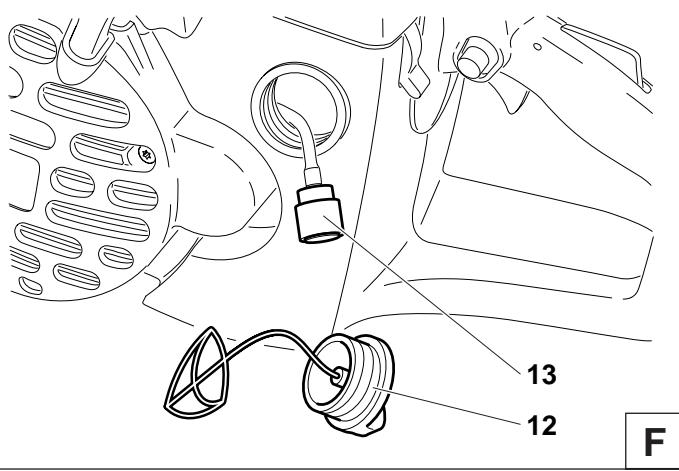
Replacing the suction head
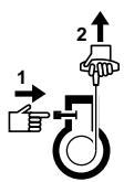
The felt filter (13) of the suction head can become clogged. It is recommended to replace the suction head once every three months in order to ensure unimpeded fuel flow to the carburetor.
Unscrew the tank cap (12), pull the retainer out of the opening. Empty fuel tank.
Use a wire hook to pull the suction out of the tank opening for replacement.
Caution: Do not allow fuel to come into contact with skin!
Replacing the starter cable


Remove four screws (14). Remove starter housing (15).
Unscrew two screws (16) and carefully remove the air guide (17) from the starter housing (15). Proceed in the order (A - B - C - D).
Remove all pieces of cable (18).
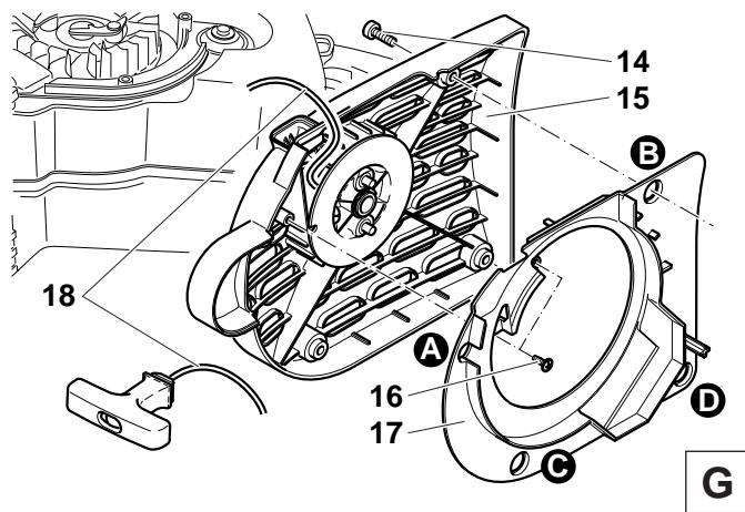
Thread in a new starter cable (dia 0.16" (4.0 mm), length 39.5" (1000 mm)) as shown (don't forget the disc (19)) and knot both ends.
Pull knot (20) into the cable pulley (21).
CAUTION: Do not let the knots or the cable ends protrude from the outside of the cable pulley.
Pull knot (22) into the cable grip (23).
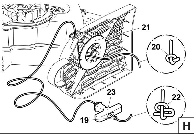
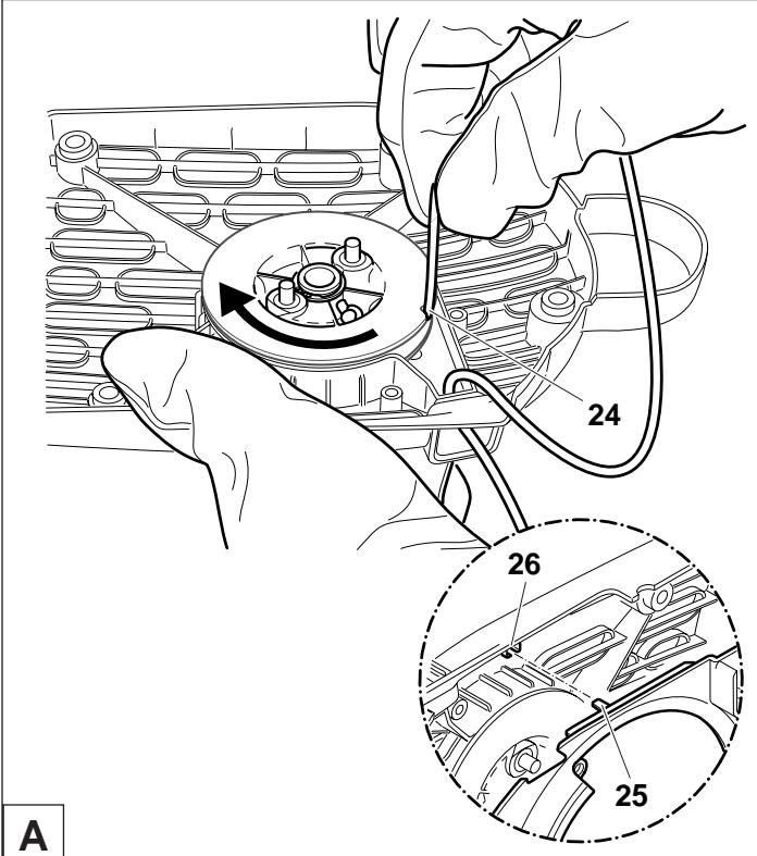
Guide the cable into the recess (24) on the cable drum and use the cable to turn the drum two turns in the direction shown by the arrow.
Holding the cable drum in your left hand, straighten out the twist in the cable with your right hand, pull the cable tight, and hold.
Release the cable drum. The drum's spring force will now wind the cable around the drum.
Repeat three times. The starter grip must be upright on the starter housing.
NOTE: With the cable pulled all the way out, it must still be possible to turn the pulley another 1/4 turn against the return spring.
CAUTION!
Injury hazard! When you pull out the starter cable hold the starter handle firmly. It will whip back if the cable pulley is released by accident.
Install the air guide in reverse order (see figure G, page 23). Make sure that the nub (25) fits into the slot (26) in the starter housing.
When putting the starter housing back on, it may be necessary to pull the starter handle slightly until the starting mechanism engages.
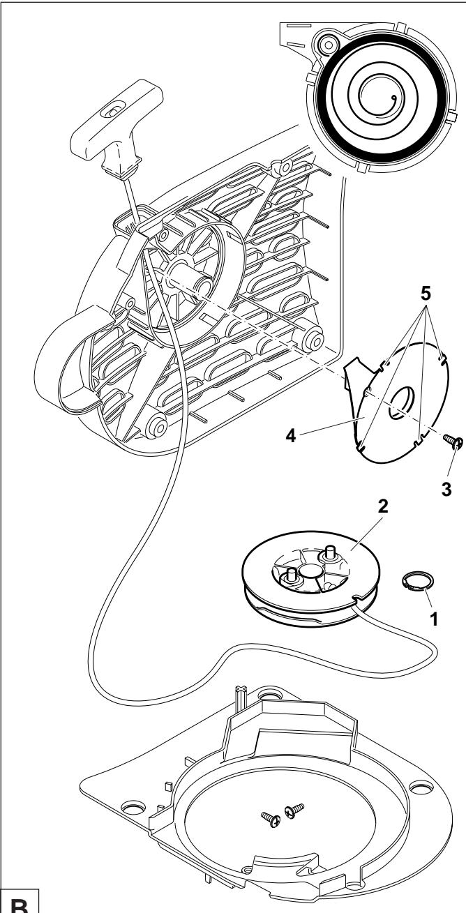
Replacing the return spring


Remove the starter housing (see "Replacing the starter cable").
Take the air guide off the starter housing (see "Replacing the starter cable").
Take off circlip (1) (circlip pliers, see "Accessories").
Remove the cable pulley (2).
Unscrew screw (3).
Evenly lever the return spring (4) out of the catch using a screwdriver or similar tool. Be extremely careful - the return spring is under tension and can pop out of its housing!
CAUTION! Injury hazard! Wear eye protection and work gloves when performing this work!
Replacement return springs are delivered already tensioned in the housing. CAREFUL - the spring can pop out. If it does, it can be put back in as shown in the diagram (observe the direction of rotation).
Before installing the new return spring (4) in the starter housing, grease it lightly with multipurpose grease, Order No. 944 360 000. Then position it and press it until the tabs (5) engage in the slots.
Do not grease the cable drum (2) or bearing journal!
Screw in bolt (3) but do not tighten it hard.
Turn the cable pulley slightly when putting it back on, until you hear it catch. Put the circlip back on.
Wind on the starter cable (see above under “Replacing the starter cable”).
Reinstall the air guide (see Fig. A)
When putting the starter housing back on, it may be necessary to pull the starter handle slightly until the starting mechanism engages.
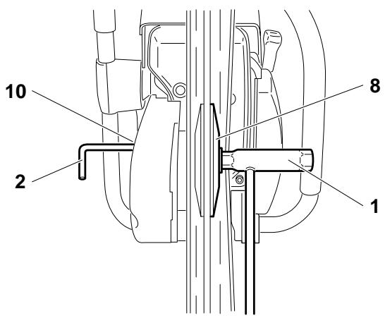
Cutting attachment in central / side position
NOTE: The Power Cut is delivered with the cutting attachment mounted in the middle position (1). For cutting up against obstacles, such as curbs or walls, the cutting attachment can be mounted to one side (2). Use this position only when actually necessary, and afterwards return the cutting attachment to the middle position. In this position the Power Cut has better balance, is easier to guide, and is not as fatiguing for the operator.
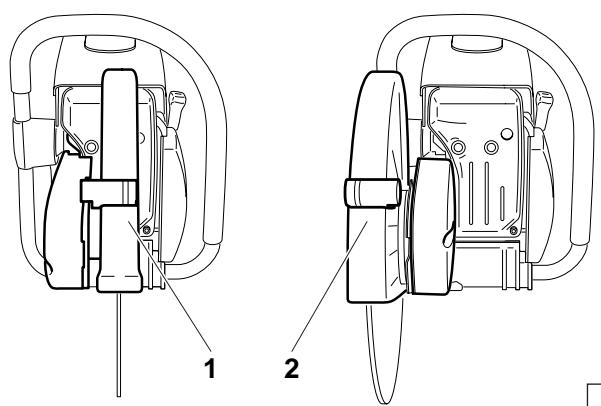
C
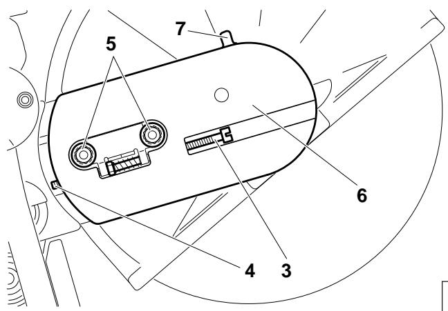
Repositioning the cutting attachment


Loosen nuts (5).
Loosen the tightening screw (3) (counter-clockwise) until the end of the screw (4) is visible in the gap.
Unscrew the nuts (5) and remove the cover (6).
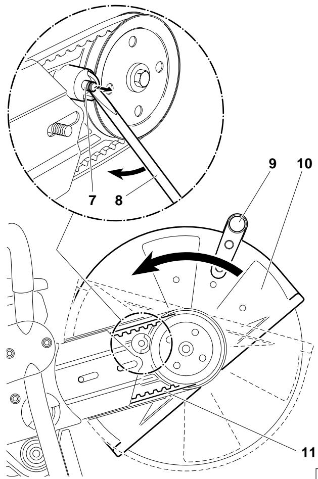
D
Use the combination tool (8) to lever out the stop pin (7) as shown in the illustration, until the protective hood (10) can be turned.
NOTE: The turn stop (D/7) is deactivated when the stop pin (7) is removed. This permits the hood (10) to be turned farther than the turn stop (D/7).
Unscrew the grip (9) and turn the protective hood (10) as shown in the illustration.
Disengage the V-belt (11) and remove the cutting attachment.
E

Press the cutting attachment (12) onto the drive arm in the side position.
Guide the V-belt (13) over the V-belt pulley (14).
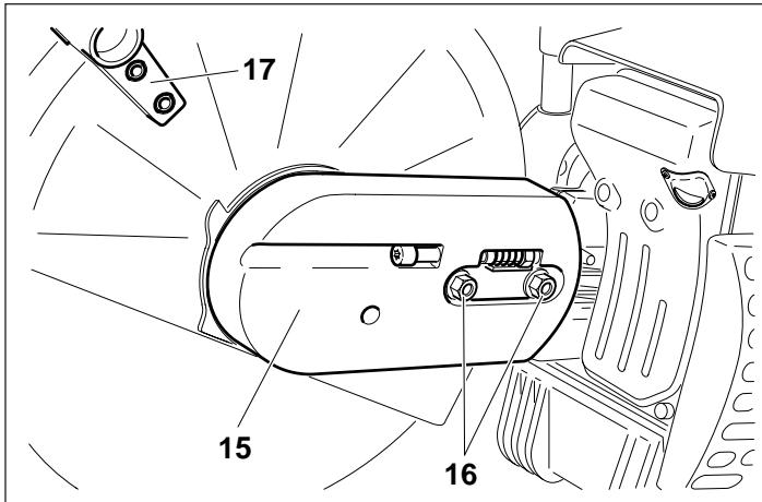
Put the guard plate (15) on.
Screw on nuts (16) and tighten by hand.
To tighten the V-belt see "Tightening the V-belt / Checking V-belt tension".
Tighten the nuts (16) firmly with the combination wrench.
Replace the grip (17) as shown.
IMPORTANT:
When you reposition the cutting attachment, the direction of rotation of the cutting wheel changes.

If a rotation direction is marked on the cutting disc, make sure the disc turns in the right direction.
G
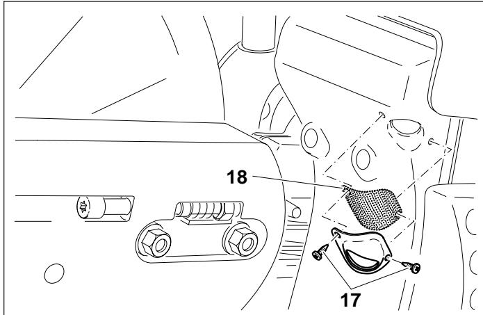
Replacing/cleaning the spark arrester screen


The spark arrester screen should be checked and cleaned regularly.
Loosen the 2 screws (18) and remove the spark arrester screen (19).
Reassembly the spark arrester screen and tighten the screws.
CAUTION:
Do not use sharp or pointed objects for screen cleaning.
Damaged or misformed screen wires may result.
H
SPECIAL ACCESSORIES
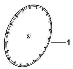
Diamond cutting discs (1)
MAKITA diamond cutting discs meet the highest demands in working safety, ease of operation, and economical cutting performance. They can be used for cutting all materials except metal.
The high durability of the diamond grains ensures low wear and thereby a very long service life with almost no change in disc diameter over the lifetime of the disc. This gives consistent cutting performance and thus high economy. The outstanding cutting qualities of the discs make cutting easier.
The metal disc plates give highly concentric running for minimal vibration during use.
The use of diamond cutting discs reduces cutting time significantly. This in turn leads to lower operating costs (fuel consumption, wear on parts, repairs, and last but not least environmental damage).
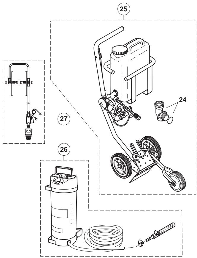
Guide trolley (2)
The MAKITA guide trolley makes it much easier to do straight cuts, while simultaneously enabling almost untiring working. It can be adjusted for the operator's height, and can be operated with the cutting attachment mounted in the middle or on the side.
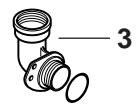
For easier refuelling when using the trolley, we recommend adding an angled tank filler neck (3).
A depth limiter can be added for still easier and more accurate cutting. It makes it possible to maintain a precise predetermined cut depth (4).
To keep down dust and for better cutting-disc cooling, MAKITA offers several options for wetting the disc during operation.
Water tank (5)
The water tank is designed to be mounted on the guide trolley. Its high capacity makes it especially suitable for situations involving frequent site changes. For filling or for fast changing to reserve tanks, the tank can be simply lifted off the trolley.
The water tank comes with all necessary connections and hoses. Mounting to the trolley and Power Cut are very fast and simple.
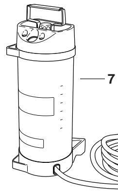
Mains/pressure water system (6)
The mains/pressure water system is designed to be mounted on the Power Cut. It can be used with or without the trolley, but is especially suitable for applications involving hand-held, stationary cutting. The water line has a fast-release connection, and can be fed either from a mains supply or from a pressure tank (7).
The water system comes with all necessary connections and lines. It can be quickly and easily mounted on the Power Cut.
See "Accessories" for order number.
natural_image
Simple oval-shaped diagram with labeled point '1' and internal markings (no text or symbols beyond labels)

natural_image
Line drawing of a cylindrical device with attached cable and ports, labeled with number 7 (no text or symbols on the device itself)

4
Instructions for periodic maintenance
To ensure long life, prevent damage and ensure the full functioning of the safety features the following maintenance must be performed regularly. Guarantee claims can be recognized only if this work is performed regularly and properly. Failure to perform the prescribed maintenance work can lead to accidents!
Users of the Power Cut must not perform any maintenance work not described in this Instruction Manual. All such work must be carried out by a MAKITA service center. Page
Page
| General | Entire Power CutCutting discClutchProtection hood | Clean exterior, check for damage. In case of damage, have repaired by a qualified service center immediatelyInspect regularly for damage and wear.Have inspected at a service center.Clean, Check position (impact plate) | 717 |
| Before each start | Cutting discV-beltProtective hoodCombination switch,Safety locking button,Throttle leverTank cap | Inspect for damage and make sure the cutting wheel is right for the jobCheck V-belt tensionAdjust positionFunctional checkFunctional checkFunctional checkCheck for tightness | 71417 |
| Every day | Air filterIdle speedExtreme dust | Clean, (poss. more often), replace foam pre-filter after 20 hours of operationCheck (cutting disc must not turn on idle)Clean filter insert (paper cartridge) | 211921 |
| Every week | Starter housingStarter cableV-beltAir filter insertSpark plugMuffler | Clean to ensure proper air coolingCheck for damageCheck V-belt tension, inspect for damage and wearClean, replace after 100 operating hoursCheck and replace if necessaryCheck tightness of mounting | 1223202222-2312 |
| Every 3 months | Suction headFuel tank | ReplaceClean | 23 |
| Annually | Entire Power Cut | Check at an authorized service center | |
| Storage | Entire Power CutCutting discFuel tankCarburetor | Clean exterior, check for damage. In case of damage, have repaired by a qualified service center immediatelyRemove and cleanEmpty and cleanRun empty | 13 |
Service, spare parts and guarantee
Maintenance and repair
The maintenance and repair of modern cutoff saws and their safety-related components requires qualified technical training and a workshop equipped with special tools and testing devices.
We therefore recommend that you consult a MAKITA service center for all work not described in this instruction manual.
The MAKITA service centers have all the necessary equipment and skilled and experienced personnel, who can work out cost-effective solutions and advise you in all matters.
Please contact your nearest service center (list enclosed) or the general trading company or importer (see last page), who will gladly provide you with the address of your nearest MAKITA service center.
Spare parts
Reliable long-term operation, as well as the safety of your Power Cut, depend among other things on the quality of the spare parts used. Use only original MAKITA parts, marked

Only original parts are from the same production line as the original unit and therefore ensure the highest possible quality of materials, dimensions, functioning and safety.
Only original spare parts and accessories guarantee the highest quality in material, dimensions and function.
Original spare parts and accessories can be obtained from your local dealer. He will also have the spare part lists to determine the required spare part numbers, and will be constantly informed about the latest improvements and spare part innovations.
Please bear in mind that if parts other than original MAKITA spare parts are used, this will automatically invalidate the MAKITA product guarantee.
We will furthermore not accept any liability damages arising from the use of non-MAKITA spare parts.
Guarantee
MAKITA guarantees the highest quality and will therefore reimburse all costs for repair by replacement of damaged parts resulting from material or production faults occurring within the guarantee period after purchase. Please note that in some countries particular guarantee conditions may exist. If you have any questions, please contact your salesman, who is responsible for the guarantee of the product.
Please note that we cannot accept any responsibility for damage caused by:
• Disregard of the instruction manual.
• Non-performance of the required maintenance and cleaning.
• Incorrect carburetor adjustment.
• Normal wear and tear.
- Obvious overloading due to permanent exceeding of the upper performance limits.
- The use of other than original MAKITA cutting discs.
• Use of force, improper use, misuse or accidents.
- Damage from overheating due to dirt on the fan housing.
• Work on the Power Cut by unskilled persons or inappropriate repairs.
• Use of unsuitable or old oil.
- Damage related to conditions arising from lease or rent contracts.
- Use of unsuitable spare parts or parts which are not original MAKITA parts, insofar as they have caused the damage.
Cleaning, servicing and adjustment work is not covered by the guarantee. All repairs covered by the guarantee must be performed by a MAKITA service center.
Troubleshooting
| Malfunction | System | Observation | Cause |
| Cutting disc does not start turning | Clutch | Engine runs | Damage to clutch |
| Cutting disc runs in idle | Carburetor, clutch | Cutting disc runs | Incorrect idle speed, blocked clutch |
| Engine does not start or only with difficulty | Ignition system | Ignition spark | Malfunction in fuel supply system, compression system, mechanical malfunction. |
| No ignition spark | Switch on STOP, fault or short-circuit in the wiring, plug cap or spark plug defective. |
| Fuel supply | Fuel tank is filled | Choke in wrong position, carburetor defective, suction head dirty, fuel line bent or interrupted. |
| Compression system | Inside | Cylinder base packing ring defective, radial shaft packings defective, cylinder or piston rings defective |
| Outside | Spark plug does not seal. |
| Mechanical malfunction | Starter does not engage | Spring in starter broken, broken parts inside the engine. |
| Engine starts, but dies immediately | Fuel supply | Fuel tank is filled | Wrong idling adjustment, suction head or carburetor dirty. Tank venting defective, fuel line interrupted, cable defective, STOP switch defective. Decompression valve dirty |
| Insufficient power | Several systems may be involved simultaneously | Engine speed is low | Air filter dirty, wrong carburetor adjustment, muffler clogged, exhaust channel in cylinder clogged, spark arrester screen clogged |
Use only original MAKITA parts. For repairs and replacement of other parts, see your MAKITA service center.
DPC6410, 6411
DPC7310, 7335

Pos. MAKITA-No.
Qty. Denomination
1 966 121 150
966 141 150
966 144 150
1 966 121 120
966 141 120
966 144 120
3 994 280 250
4 965 300 470
5 963 601 120
6 010 114 091
8 394 173 020
9 394 173 010
10 326 173 080
11 965 603 021
12 122 164 010
13 001 161 020
14 394 163 020
15 923 208 004
16 941 719 140
17 940 827 000
18 944 340 001
19 394 174 140
Synthetic resin cutting disc
1 Cutting disc for steel, dia. 300/20 mm (12"/0.8")
1 Cutting disc for steel, dia. 350/20 mm (14"/0.8")
1 Cutting disc for steel,
dia. 350/25,4 mm (14"/1.0")
1 Cutting disc for masonry, dia. 300/20 mm (12"/0.8")
1 Cutting disc for masonry, dia. 350/20 mm (14"/0.8")
1 Cutting disc for masonry, dia. 350/25,4 mm (14"/1.0")
1 Hex screw M8x25
1 V-belt
1 Suction head
1 Tank cap, compl. (fuel)
1 Inner filter
1 Air filter insert (paper cartridge)
1 Pre-filter (foam)
1 Spark plug
1 Starter cable ∅4,0x1000 mm
1 Starter grip
1 Return spring in housing
2 Hexagonal nut M8
1 Universal wrench SW 13/19
1 Offset screwdriver T27
1 Screwdriver (carburetor)
1 Spark arrester screen cpl.
Accessories (not delivered with the Power Cut)
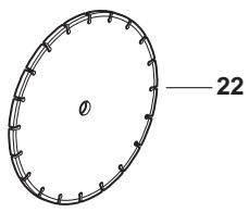
Diamond cutting disc
12"/0.8"
22 966 221 020
22 966 321 020
22 966 221 010
22 966 321 010
Concrete Standard, dia. 300/20 mm
Concrete DiaDuran, dia. 300/20 mm
Asphalt Standard, dia. 300/20 mm
Asphalt DiaDuran, dia. 300/20 mm
14"/0.8"
22 966 241 020
22 966 341 020
22 966 241 010
22 966 341 010
Concrete Standard, dia. 350/20 mm
Concrete DiaDuran, dia. 350/20 mm
Asphalt Standard, dia. 350/20 mm
Asphalt DiaDuran, dia. 350/20 mm
14"/1.0"
22 966 244 020
22 966 344 020
22 966 244 010
22 966 344 010
Concrete Standard, dia. 350/25,4 mm
Concrete DiaDuran, dia. 350/25,4 mm
Asphalt Standard, dia. 350/25,4 mm
Asphalt DiaDuran, dia. 350/25,4 mm
- 394 228 121
24 010 114 081
25 700 394 353
26 957 802 600
27 394 365 630
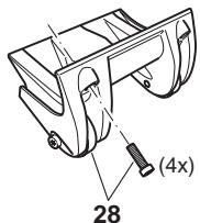
28 394 114 270
- 949 000 031
Adapter ring, dia. 0.8"/1.0" (20/25,4 mm)
Angle fuel-tank filler neck, cpl.
Guide trolley DT2000 cpl.
Pressure water tank, cpl.
Mains water connection, cpl.
Stand with rollers, compl.
Combined can (for 5l fuel, 2.5l oil)
EMISSIONS COMPONENT DEFECT WARRANTY COVERAGE
Attention,
Rebond (kickback)!
Mélange carburant
Premier secours
Recyclage
INSTRUCTIONS DE SÉCURITÉ
Découpeuse
natural_image
Illustration of a wine bottle and a smaller bottle with scattered pills, no text or symbols present
2
natural_image
Line drawing of a helmet with labeled parts A and B, showing front, side, and interior views (no text or symbols beyond labels)
natural_image
Line drawings of two safety goggles labeled D and C (no text or symbols on the diagrams)
3
natural_image
Line drawing of a gasifier with mesh casing and handle (no text or symbols)
E
natural_image
Line drawing of a pair of gloves with visible bands and soles (no text or symbols)
F
4
natural_image
Illustration of a boot labeled G and a worker wearing a hard hat (no text or symbols on the boots or worker)
natural_image
Diagram showing a mechanical device with a tool and cross-sectional view, no readable text or symbols present

natural_image
Two abstract diagrams showing a black circular object with intersecting lines and a gray wind turbine blade, both without any text or symbols.

natural_image
Two-panel illustration showing workers on a ladder and a welding helmet, both without any text or symbols.
natural_image
Illustration of a worker using a power tool on a bench, no text or symbols present
Découper les métaux
ATTENTION!
natural_image
Illustration of a person using a cutting tool on a workbench, with sparks flying (no text or symbols)
geo
| Region | Value |
|--------|-------|
| 1 | 1 |
| 2 | 2 |
| 3 | 3 |
| 4 | 4 |
| 5 | 5 |
| 6 | 6 |
| 7 | 7 |

flowchart
graph TD
    A["Top Left"] --> B["Bottom Left"]
    B --> C["Top Right"]
    C --> D["Bottom Right"]
    style A fill:#f9f,stroke:#333
    style D fill:#bbf,stroke:#333
    subgraph Left
        E["1"] --> F["2"]
        G["2"] --> H["3"]
    end
    subgraph Right
        I["1"] --> J["2"]
        K["3"] --> L["4"]
    end
    style E fill:#fff,stroke:#000
    style G fill:#fff,stroke:#000
    style K fill:#fff,stroke:#000
natural_image
Illustration of a person using a cutting tool on a workbench, with sparks flying (no text or symbols)

natural_image
Technical line drawing of a mechanical power tool with pump and motor components (no text or symbols)

natural_image
Diagram showing a hammer striking a block with a downward arrow, no text or symbols present

Maintenance
natural_image
Simple black-and-white cross symbol on white background (no text or symbols)
29


A

B
MISE EN ROUTE
ATTENTION:
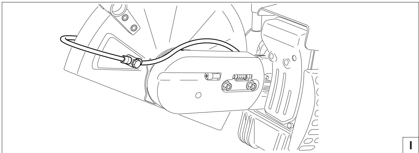
natural_image
Technical line drawing of a mechanical assembly with hoses and components (no text or symbols)
Carburants
ATTENTION:

other
| Carburant | 100:1 | 50:1 |
| --------- | ----- | ---- |
| Gasoline + 2.5 US-gal. (3.7 litres) | 1.25 floz. (37 cm³) | 2.5 floz. (75 cm³) |
| Gasoline + 2.5 US-gal. (9.4 litres) | 3.2 floz. (94 cm³) | 6.4 floz. (189 cm³) |
| Gasoline + 2.5 US-gal. (18.9 litres) | 6.4 floz. (189 cm³) | 12.8 floz. (378 cm³) |
natural_image
Line drawing of a car interior showing dashboard, air vent, and control knobs (no text or symbols)
C
ATTENTION:
E
Démarrage à froid
F

G
C

A
TRAVAUX DE MAINTENANCE
ATTENTION:
A
natural_image
Technical line drawing of a mechanical device with two views labeled 1 and 2 (no text or symbols present)
C
D
E
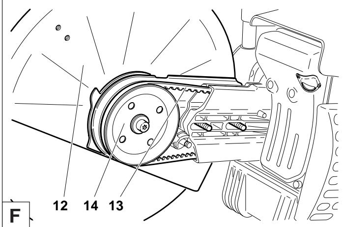
natural_image
Simple oval-shaped diagram with evenly spaced segments and a central label (no text or symbols)
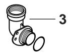

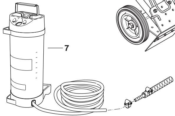
natural_image
Technical line drawing of a mechanical device with labeled components (no text or symbols present)
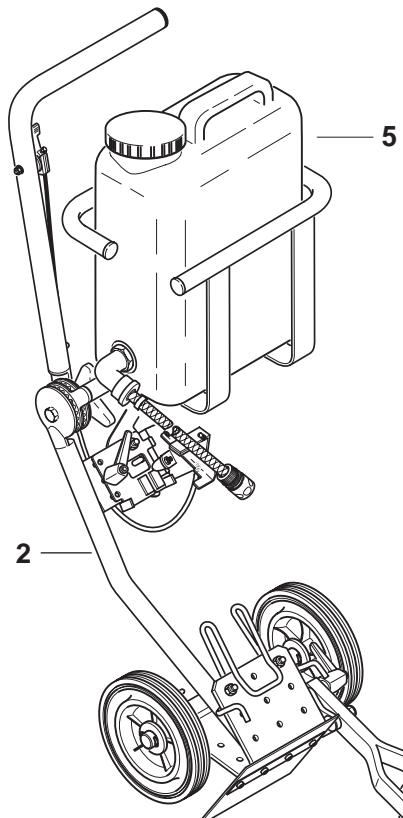
Pos. N°MAKITA pcs. Désignation
natural_image
Two black-and-white symbols: a circle with an open book and a triangular warning sign with an exclamation mark (no text or numbers present)
2

natural_image
Illustration of two bottles with scattered pills, no text or symbols present
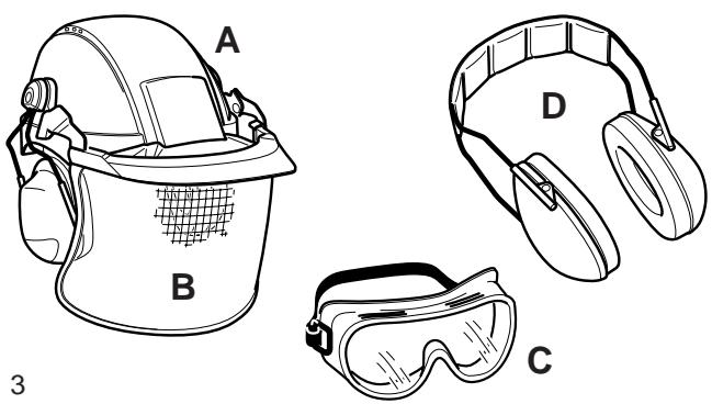
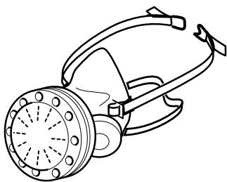
natural_image
Line drawing of a gas purifier with handle and spout (no text or symbols)
E
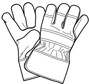
natural_image
Line drawing of a pair of gloves with bandages and straps (no text or symbols)
F
4
natural_image
Illustration of a boot labeled G and a worker wearing a hard hat (no text or symbols on the boots or worker)


natural_image
Diagram showing a mechanical device with a tool and cross-sectional view, no readable text or symbols present
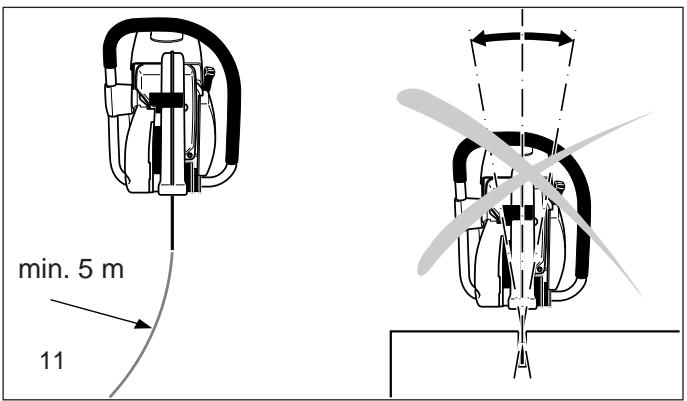

natural_image
Two abstract diagrams showing a black circular object with intersecting lines and a gray wind turbine blade, both without any text or symbols.
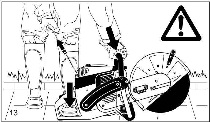
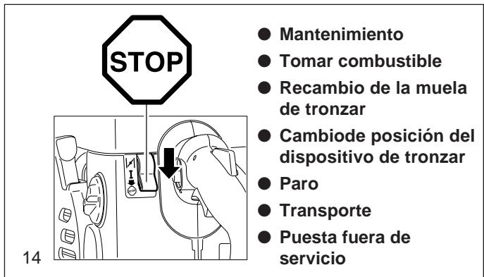
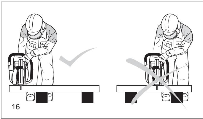
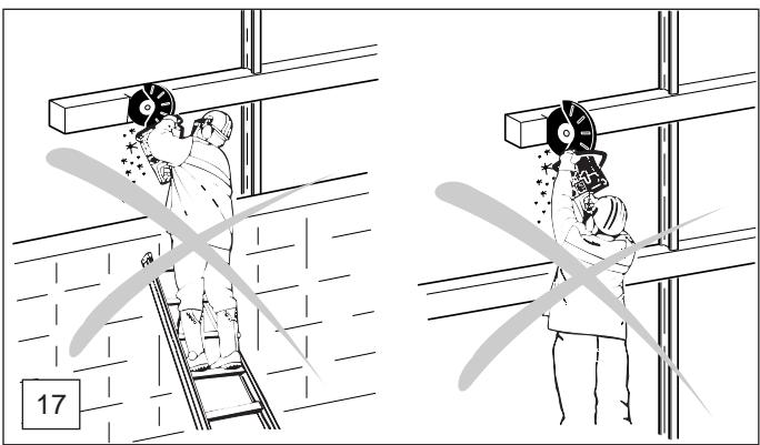
natural_image
Two-panel illustration showing workers on a ladder and a grinding cutter, both without any text or symbols.

natural_image
Illustration of a worker operating a mechanical device on a bench, no text or symbols present
natural_image
Illustration of a person using a cutting tool on a workbench, with sparks flying (no text or symbols)

geo
| Label | Value |
|-------|-------|
| 1 | 1 |
| 2 | 2 |
| 3 | 3 |
| 4 | 4 |
| 5 | 5 |
| 6 | 6 |
| 7 | 7 |

flowchart
graph TD
    A["Top Left"] --> B["Bottom Left"]
    B --> C["1"]
    B --> D["2"]
    B --> E["3"]
    F["Bottom Right"] --> G["Top Right"]
    G --> H["1"]
    G --> I["2"]
    G --> J["3"]
    style A fill:#f9f,stroke:#333
    style F fill:#ccf,stroke:#333
    style G fill:#cfc,stroke:#333
natural_image
Illustration of a person using a cutting tool on a workpiece, with sparks flying (no text or symbols)
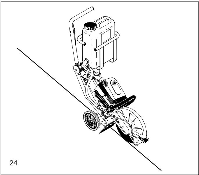
natural_image
Technical line drawing of a mechanical power tool with pump and motor components (no text or symbols)

natural_image
Diagram showing a hammer striking a block with a downward arrow, no text or symbols present
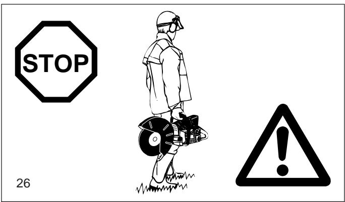
Mantenimiento
natural_image
Simple black-and-white cross symbol on white background (no text or symbols)
29
Datos técnicos
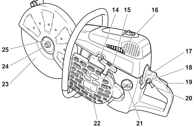

A
PUESTA EN MARCHA
ATENCION:
B
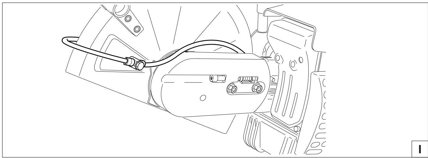
natural_image
Technical line drawing of a mechanical assembly with hoses and components (no text or symbols)
Combustibles
ATENCION:
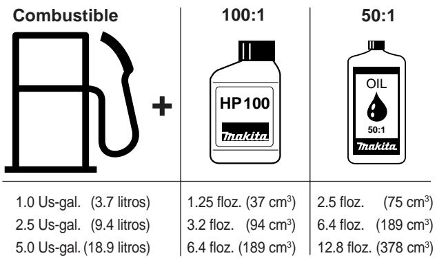
other
Combustible + 100:1 50:1
1.0 Us-gal. (3.7 litros) 1.25 floz. (37 cm³) 2.5 floz. (75 cm³)
2.5 Us-gal. (9.4 litros) 3.2 floz. (94 cm³) 6.4 floz. (189 cm³)
5.0 Us-gal. (18.9 litros) 12.8 floz. (378 cm³)
natural_image
Line drawing of a car interior showing dashboard, air vent, and control panel (no text or symbols)
C
ATENCION:
E
Arranque en frío
F
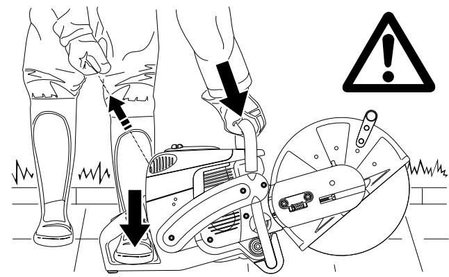
G
C

A
MANTENIMIENTO
ATENCIÓN:
A
Filtro previo (espuma) y filtro interior
C
D
E
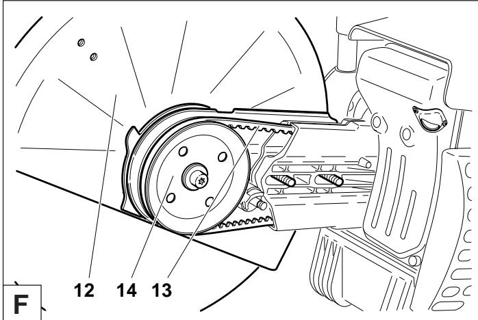
natural_image
Simple oval-shaped diagram with labeled point '1' and internal markings (no text or symbols beyond labels)
3
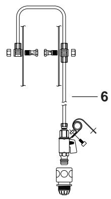

natural_image
Technical line drawing of a mechanical device with coiled cable, pump, and tool (no text or symbols)
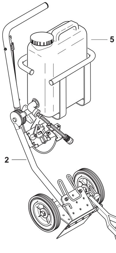
Pos. No. MAKITA
No. Denominación