
CMXGVAM1144043 - Rototiller Craftsman - Free user manual and instructions
Find the device manual for free CMXGVAM1144043 Craftsman in PDF.


| Product Type | Rototiller |
| Brand | Craftsman |
| Model | CMXGVAM1144043 |
| Engine Type | 4-Stroke Gasoline Engine |
| Engine Displacement | 208 cc |
| Starting System | Recoil Start |
| Tilling Width | 24 inches |
| Tilling Depth | Up to 10 inches |
| Number of Tines | 4 forward, 2 reverse |
| Number of Forward Speeds | 2 |
| Reverse | 1 speed |
| Fuel Type | Unleaded gasoline |
| Fuel Capacity | 1.5 quarts |
| Oil Capacity | 20 oz |
| Weight | Approximately 110 lbs |
| Dimensions (L x W x H) | 45 x 24 x 40 inches |
| Wheel Size | 10 inches |
| Safety Features | Operator presence lever, belt guard, engine kill switch |
| Maintenance | Check oil before each use; clean air filter after 25 hours; change oil every 50 hours |
| Warranty | 2-year limited warranty |
Frequently Asked Questions - CMXGVAM1144043 Craftsman
User questions about CMXGVAM1144043 Craftsman
0 question about this device. Answer the ones you know or ask your own.
Ask a new question about this device
Download the instructions for your Rototiller in PDF format for free! Find your manual CMXGVAM1144043 - Craftsman and take your electronic device back in hand. On this page are published all the documents necessary for the use of your device. CMXGVAM1144043 by Craftsman.
USER MANUAL CMXGVAM1144043 Craftsman
Before setting up and operating your new equipment, please locate the model plate on the equipment and record the information in the provided area to the right. You can locate the model plate by standing at the operator's position and looking down at the tine shield. This information will be necessary, should you seek technical support via our web site, Customer Support Department, or with a local authorized service dealer.
MODEL NUMBER

natural_image
Row of identical empty rectangular boxes with no text or symbolsSERIAL NUMBER

natural_image
Grid of identical empty rectangular boxes with no text or symbolsTable of Contents
Safe Operation Practices 2
Assembly & Set-Up.... 4
Controls & Operation 6
Service....8
Troubleshooting....9
Español....11
Replacement Parts ...... See Separate Supplement
Warranty ...... See Separate Supplement
WARNING
Read and follow all safety rules and instructions in this manual before attempting to operate this machine. Failure to comply with these instructions may result in personal injury.
WARNING
California Proposition 65
Engine Exhaust, some of its constituents and certain vehicle components contain or emit chemicals known to the State of California to cause cancer and birth defects or other reproductive harm.
Battery posts, terminals and related accessories contain lead and lead compounds, chemicals known to the State of California to cause cancer and reproductive harm. Wash hands after handling.
NOTE: This Operator's Manual covers several models. Features may vary by model. Not all features in this manual are applicable to all models and the model depicted may differ from yours.
SAFE OPERATION PRACTICES
WARNING
This symbol points out important safety instructions which, if not followed, could endanger the personal safety and/or property of yourself and others. Read and follow all instructions in this manual before attempting to operate this machine. Failure to comply with these instructions may result in personal injury. When you see this symbol - HEED ITS WARNING!
DANGER
This machine was built to be operated according to the safe operation practices in this manual. As with any type of power equipment, carelessness or error on the part of the operator can result in serious injury. This machine is capable of amputating hands and feet and throwing debris. Failure to observe the following safety instructions could result in serious injury or death.
Training
- Read, understand and follow all instructions on the machine and in the manual(s) before attempting to assemble and operate. Keep this manual in a safe place for future and regular reference and for ordering replacement parts.
- Be familiar with all controls and their proper operation. Know how to stop the machine and disengage it quickly.
- Never allow children under 14 years of age to operate this machine. Children 14 and over should read and understand the instructions and safe operation practices in this manual and on the machine and be trained and supervised by an adult.
- Never allow adults to operate this machine without proper instruction.
- Keep the area of operation clear of all persons, particularly small children and pets. Stop machine if anyone enters the area.
Preparation
- Thoroughly inspect the area where the equipment is to be used. Remove all stones, sticks, wire and other foreign objects which could be tripped over and cause personal injury.
- Wear sturdy, rough-soled work shoes and close fitting slacks and shirt. Loose fitting clothes or jewelry can be caught in moving parts. Never operate this machine in bare feet or sandals.
- Disengage clutch levers and shift (if provided) into neutral ("N") before starting the engine.
- Never leave this machine unattended with the engine running.
- Never attempt to make any adjustments while engine is running, except where specifically recommended in the operator's manual.
Safe Handling of Gasoline:
- To avoid personal injury or property damage use extreme care in handling gasoline. Gasoline is extremely flammable and the vapors are explosive. Serious personal injury can occur when gasoline is spilled on yourself or your clothes which can ignite. Wash your skin and change clothes immediately.
- Use only an approved gasoline container.
- Never fill containers inside a vehicle or on a truck or trailer bed with a plastic liner. Always place containers on the ground away from your vehicle before filling.
- When practical, remove gas-powered equipment from the truck or trailer and refuel it on the ground. If this is not possible, then refuel such equipment on a trailer with a portable container, rather than from a gasoline dispenser nozzle.
- Keep the nozzle in contact with the rim of the fuel tank or container opening at all times until fueling is complete. Do not use a nozzle lock-open device.
- Extinguish all cigarettes, cigars, pipes and other sources of ignition.
- Never fuel machine indoors.
- Never remove gas cap or add fuel while the engine is hot or running. Allow engine to cool at least five minutes before refueling.
- Never over fill fuel tank. Fill tank to no more than 1/2 inch below bottom of filler neck to allow space for fuel expansion.
- Replace gasoline cap and tighten securely.
- If gasoline is spilled, wipe it off the engine and equipment. Move unit to another area. Wait five minutes before starting the engine.
- To reduce fire hazards, keep machine free of grass, leaves or other debris build-up. Clean up oil or fuel spillage and remove any fuel soaked debris.
- Never store the machine or fuel container inside where there is an open flame, spark or pilot light as on a water heater, space heater, furnace, clothes dryer or other gas appliances.
Operation
- Do not put hands or feet near rotating parts. Contact with the rotating parts can amputate hands and feet.
- Always wear safety glasses or safety goggles during operation and while performing an adjustment or repair to protect your eyes. Thrown objects which ricochet can cause serious injury to the eyes.
- For extended use of this product, hearing protection is required.
- Do not operate machine while under the influence of alcohol or drugs.
-
Never operate this machine without good visibility or light. Always be sure of your footing and keep a firm hold on the handles.
-
Keep bystanders away from the machine while it is in operation. Stop the machine if anyone enters the area.
- Be careful when tilling in hard ground. The tines may catch in the ground and propel the tiller forward. If this occurs, let go of the handle bars and do not restrain the machine.
- Exercise extreme caution when operating on or crossing gravel surfaces. Stay alert for hidden hazards or traffic. Do not carry passengers.
- Never operate the machine at high transport speeds on hard or slippery surfaces.
- Exercise caution to avoid slipping or falling.
- Look down and behind and use care when in reverse or pulling machine towards you.
- Start the engine according to the instructions found in this manual and keep feet well away from the tines at all times.
- After striking a foreign object, stop the engine, disconnect the spark plug wire and ground against the engine. Thoroughly inspect the machine for any damage. Repair the damage before starting and operating.
- Disengage all clutch levers (if fitted) and stop engine before you leave the operating position (behind the handles). Wait until the tines come to a complete stop before unclogging the tines or making any adjustments or inspections.
- Never run an engine indoors or in a poorly ventilated area. Engine exhaust contains carbon monoxide, an odorless and deadly gas.
- Muffler and engine become hot and can cause a burn. Do not touch.
- Use caution when tilling near fences, buildings and underground utilities. Rotating tines can cause property damage or personal injury.
- Do not overload machine capacity by attempting to till soil too deep at too fast of a rate.
- If the machine should start making an unusual noise or vibration, stop the engine, disconnect the spark plug wire and ground it against the engine. Inspect thoroughly for damage. Repair any damage before starting and operating.
- Keep all shields, guards and safety devices in place and operating properly.
- Never pick up or carry machine while the engine is running.
- Use only attachments and accessories approved by the manufacturer. Failure to do so can result in personal injury.
- If situations occur which are not covered in this manual, use care and good judgement. Contact Customer Support for assistance and the name of your nearest servicing dealer.
Maintenance & Storage
- Keep machine, attachments and accessories in safe working order.
- Allow a machine to cool at least five minutes before storing. Never tamper with safety devices. Check their proper operation regularly.
- Check bolts and screws for proper tightness at frequent intervals to keep the machine in safe working condition. Also, visually inspect machine for any damage.
- Before cleaning, repairing or inspecting, stop the engine and make certain the tines and all moving parts have stopped. Disconnect the spark plug wire and ground it against the engine to prevent unintended starting.
-
Do not change the engine governor settings or over-speed the engine. The governor controls the maximum safe operating speed of engine.
-
Maintain or replace safety and instruction labels, as necessary.
-
Follow this manual for safe loading, unloading, transporting and storage of this machine.
-
Always refer to the Operator's Manual for important details if the machine is to be stored for an extended period.
-
If the fuel tank has to be drained, do this outdoors.
-
Observe proper disposal laws and regulations for gas, oil, etc. to protect the environment.
-
According to the Consumer Products Safety Commission (CPSC) and the U.S. Environmental Protection Agency (EPA), this product has an Average Useful Life of seven (7) years, or 130 hours of operation. At the end of the Average Useful Life have the machine inspected annually by an authorized service dealer to ensure that all mechanical and safety systems are working properly and not worn excessively. Failure to do so can result in accidents, injuries or death.
SAFE OPERATION PRACTICES
Notice Regarding Emissions
Engines which are certified to comply with California and federal EPA emission regulations for SORE (Small Off Road Equipment) are certified to operate on regular unleaded gasoline, and may include the following emission control systems: Engine Modification (EM), Oxidizing Catalyst (OC), Secondary Air Injection (SAI) and Three Way Catalyst (TWC) if so equipped.
Spark Arrestor
WARNING
This machine is equipped with an internal combustion engine and should not be used on or near any unimproved forest-covered, brushcovered or grass-covered land unless the engine's exhaust system is equipped with a spark arrestor meeting applicable local or state laws (if any).
If a spark arrestor is used, it should be maintained in effective working order by the operator. In the State of California the above is required by law (Section 4442 of the California Public Resources Code). Other states may have similar laws. Federal laws apply on federal lands.
A spark arrestor for the muffler is available through your nearest engine authorized service dealer or contact the service department, P.O. Box 361131 Cleveland, Ohio 44136-0019.
Safety Symbols
This page depicts and describes safety symbols that may appear on this product. Read, understand and follow all instructions on the machine before attempting to assemble and operate.
| Symbol Description | |
 | READ THE OPERATOR'S MANUAL(S)Read, understand and follow all instructions in the manual(s) before attempting to assemble and operate. |
 | WARNING—ROTATING TINESDo not put hands or feet near rotating parts. Contact with the rotating parts can amputate hands and feet. |
WARNING
Your Responsibility — Restrict the use of this power machine to persons who read, understand and follow the warnings and instructions in this manual and on the machine. SAVE THESE INSTRUCTIONS!
ASSEMBLY & SET-UP
Thank You
Thank you for purchasing this product. It was carefully engineered to provide excellent performance when properly operated and maintained.
Please read this entire manual prior to operating the equipment. It instructs you how to safely and easily set up, operate and maintain your machine. Please be sure that you, and any other persons who will operate the machine, carefully follow the recommended safety practices at all times. Failure to do so could result in personal injury or property damage.
All information in this manual is relative to the most recent product information available at the time of printing. Review this manual frequently to familiarize yourself with the machine, its features and operation. Please be aware that this Operator's Manual may cover a range of product specifications for various models. Characteristics and features discussed and/or illustrated in this manual may not be applicable to all models. We reserve the right to change product specifications, designs and equipment without notice and without incurring obligation.
If you have any problems or questions concerning the machine, phone your local authorized dealer or contact us directly. We want to ensure your complete satisfaction at all times.
Throughout this manual, all references to right and left side of the machine are observed from the operating position.
Contents of Carton
• Tiller
- Handlebar Assembly
- Depth Stake Assembly
• Tine Assemblies (4)
- Wheel Assembly
- Bottle of Oil
- Operator's Manual
• Engine Operator's Manual
Assembly
References to right and left side of tiller are determined from behind the equipment in the operating position except where otherwise specified.
Recommended Tools for Assembly
- 1/2" wrench
- Clean oil funnel
- Motor oil. Refer to the Engine Operator's Manual for oil specifications and quantity required.
Tines
The tines must be installed correctly to ensure proper operation. See below for the proper tine installation:
- The tines must be installed in the correct location and the correct order. Each time is marked as follows:
• A1 — Inner LH Tine
• A2 — Outer LH Tine
• B1 — Inner RH Tine
• B2 — Outer RH Tine
NOTE: Images and descriptions of tine installation are referenced from the FRONT of the tiller.
-
Use two clevis pins and two cotter pins from the manual bag. From the FRONT of the tiller install the inner LH tines (A1) onto the inner left side of the shaft. Install the inner RH tines (B1) onto the inner right side of the shaft. See Figure 1.
-
Use two clevis pins and two cotter pins from the manual bag. From the FRONT of the tiller install the outer LH tines (A2) onto the outer left side of the shaft. Install the outer RH tines (B2) onto the outer right side of the shaft. See Figure 2.
NOTE: Tilling width varies by model. For models 21B-34M8766 and 21B-34M8793, the outer tines can be placed in either of the two outside holes. The inner hole is for a 22" tilling width and the outer hole is for a 24" tilling width. For model 21B-34M8710, the outer tines can be placed in either of the two outside holes. The inner hole is for a 24" tilling width and the outer hole is for a 26" tilling width.
Wheel Assembly &
Depth Stake Assembly
-
Remove the remaining clevis pin and cotter pin from the manual bag, install the wheel assembly into the chain case bracket as shown in Figure 3.
-
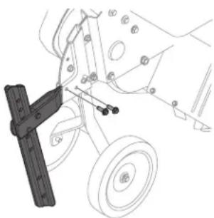
Remove the two screws from the bracket in the chain case. See Figure 4.
-
Insert the horizontal bracket into the chain case brackets and secure the depth stake assembly in place with the screws removed in Step 2. See Figure 4.
NOTE: The depth stake can be placed at various positions. For setup purposes it is suggested that the depth stake be assembled with the stake just above or level with the ground surface. See the Controls & Operation section for instructions on setting the tilling depth and adjusting the depth stake.
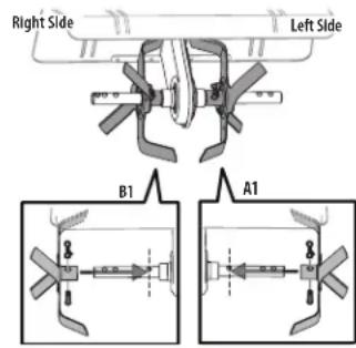
Figure 1

Figure 2
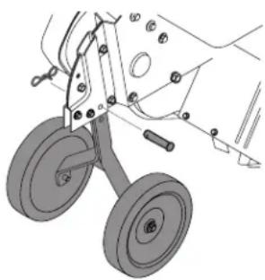
natural_image
Technical line drawing of a mechanical device with two wheels and adjustment knobs (no text or symbols)Figure 3
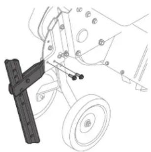
natural_image
Technical line drawing of a mechanical assembly with levers and wheels (no text or symbols)Figure 4
ASSEMBLY & SET-UP
Handle
The handle is tilted down and packaged loose for shipping purposes. To attach the handle, proceed as follows:
- Remove the bolts, washers and nuts from the chain case bracket. See Figure 5.
- Place the handle into position and secure with the previously removed hardware. See Figure 5.
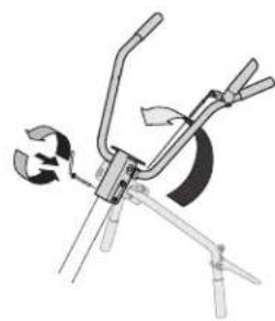
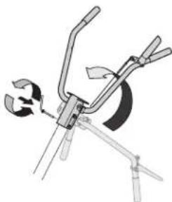
- Remove the handle adjustment crank from the handle. See Figure 6.
- Rotate the handle upward and secure it in place with the handle adjustment crank. See Figure 6.
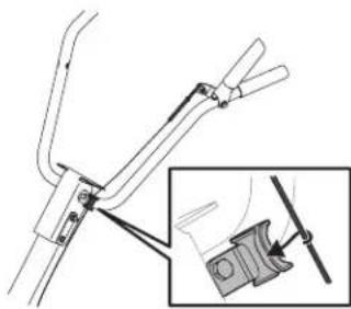
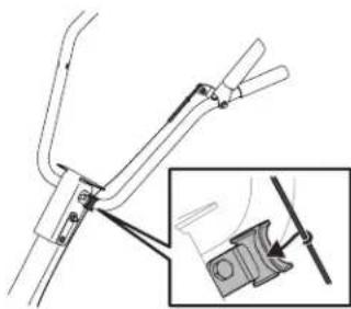
- When the handle is in place, insert the clutch cable into the cable guide on the handle as shown in Figure 7.
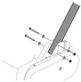
natural_image
Diagram of a hand holding a tool with a ruler, showing alignment points (no text or labels)Figure 5
natural_image
Diagram of a mechanical device with lever and clamping mechanism (no text or symbols)Figure 6
natural_image
Technical diagram of a mechanical clamp or bracket assembly with an inset showing a close-up detail (no text or symbols)Figure 7
Adjustments

WARNING
Prior to operating your tiller, carefully read and follow all instructions below. Perform all adjustments to verify your tiller is operating safely and properly.
Wheels
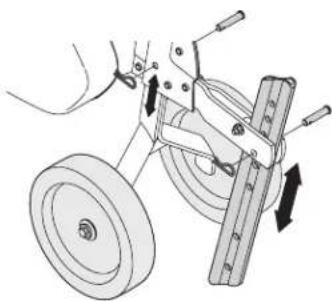
The tiller is shipped with the wheels adjusted so that the machine sits level. The wheels need to be adjusted to meet your tilling needs before operation. This adjustment is made by removing the clevis pin from the wheel yoke and raising the wheels to the desired height. See Figure 8.
Depth Stake
The depth stake can also be set to adjust the tilling depth. To raise or lower the depth stake, remove the clevis pin and cotter pin, place the depth stake in the desired position and reinstall the hardware. See Figure 8.
NOTE: See the Controls & Operation section for more information.
natural_image
Mechanical diagram showing a pulley system with weights and motion arrows (no text or symbols)Figure 8
Clutch Cable Adjustment
Before operating the tiller, the adjustment of the forward clutch cable must be checked.
- Disconnect and ground the spark plug wire against the engine.
- Adjust the forward clutch cable by loosening the hex nut. See Figure 9.
- Turn the cable collar section one or two turns to increase or decrease tension on the cable. See Figure 9.
- Retighten the hex nut against the cable collar. See Figure 9.
- With the forward engagement handle in the neutral (released) position, pull the starter rope several times. The tines should not turn.
- If they turn, adjust the forward clutch cable to release tension using the previous steps in this section.
- Check again for correct tension on the cable.
- After tilling, if the tines stop moving, re-adjust the cable.
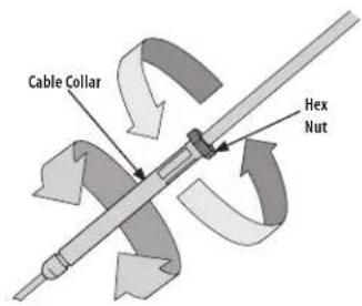
Figure 9
Set-Up
Gas & Oil Fill-Up
Service the Engine with gasoline and oil as instructed in the separate Engine Operator's Manual packed with your tiller. Read the instructions carefully.

WARNING
Use extreme care when handling gasoline. Gasoline is extremely flammable and the vapors are explosive. Never fuel the machine indoors or while the engine is hot or running.
Figure 10
WARNING
The operation of any tiller can result in foreign objects being thrown into the eyes, which can damage your eyes severely. Always wear safety glasses during operation or while performing any adjustments or repairs.
Engine Controls
See the separate Engine Operator's Manual for information and functions of the engine controls.
Clutch Lever
The clutch lever is located on the upper left handle. Squeezing the lever against the handle engages the tine drive. Release the lever to stop the tines.
Depth Stake
The depth stake acts as a brake for the tiller and controls the depth and speed at which the machine will operate.
Tines
The tines are used to cultivate, furrow and prepare your garden for seeding.
Handle Adjustment Crank
The handle height may be adjusted. Loosen the crank to change the position. Tighten the crank when the desired height is achieved.
Starting & Stopping the Engine
WARNING
Read, understand and follow all the instructions and warnings posted on the machine and in this manual before operating.
WARNING
Be sure no one is standing in front of the tiller while the engine is running or being started.
- Make sure that the tine clutch control is disengaged and refer to the Engine Operator's Manual for engine starting and stopping instructions.
Engaging the Drive & Tines
- For forward motion of the wheels and power to the tines pull the Forward Clutch Bail up against the handlebar.
- When tilling, relax and let the wheels pull the machine while the tines dig. Walk slowly behind the tiller allowing it to move at its own pace while keeping a secure grip on the handlebar with your elbows flexed.
- Release the bail to stop the forward motion of wheels and tines.
Turning the Tiller
- Practice turning the tiller in a level, open area. Be very careful to keep your feet and legs away from the tines.
- To begin a turn, lift the handlebars until the tines are out of the ground and the engine and tines are balanced over the wheels.
- With the tiller balanced, push sideways on the handlebar to steer in the direction of the turn. After turning, slowly lower the tines into the soil to resume tilling.
Setting the Depth
WARNING
Be certain spark plug wire is disconnected and grounded against the engine when performing any adjustments.
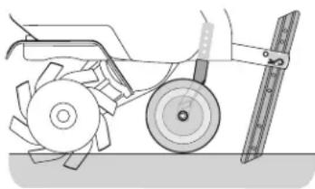
Wheel Yoke Forward
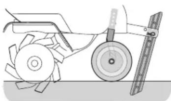
Place the wheel yoke so that wheels are forward (nearest to tines) for shallow tilling, cultivating and transport. See Figure 11.
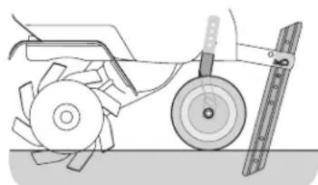
Wheel Yoke to Back
Place the wheel yoke so that wheels are toward the rear (closest to depth stake) for deep tilling and cultivating. See Figure 12.
natural_image
Technical line drawing of a mechanical tool with rotating components and a ruler (no text or symbols)Figure 11
natural_image
Technical illustration of a mechanical assembly with a blade, rotor, and cutting tool (no text or symbols)Figure 12
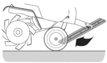
The depth stake acts as a brake for the tiller and controls the depth and speed at which the machine will operate. Remove the clevis pin and cotter pin to raise or lower depth stake. See Figure 13.
Handle Pressure
Further control of the tilling depth and travel speed can be achieved by varying pressure placed on the handles.
natural_image
Technical line drawing of a mechanical cutter tool with blades and blade (no text or symbols)Figure 13
A downward pressure on the handles will reduce the working depth and increase the forward speed. An upward pressure on the handles will increase the working depth and reduce the forward speed.
The type of soil and working conditions will determine the actual setting of the depth stake and the handle pressure required.
Clearing the Tines
WARNING
Before clearing the tines by hand, stop the engine, allow all moving parts to stop and disconnect the spark plug wire. Failure to follow this warning could result in personal injury.
The tines have a self-clearing action which eliminates most of the debris. However, occasionally debris may become tangled. Follow these procedures to help avoid tangling and to clear the tines, if necessary.
- Try to till under crop residues or cover crops while they are green, moist and tender.
- While tilling, try swaying the handlebars from side to side (about 6 to 12 inches). This "fishtailing" action often clears the tines of debris.
Transporting & Storing the Tiller
To transport and store the tiller move the throttle to the stop position. Pivot the depth stake away from the ground up between the wheels. See Figure 13.
Using the Tiller
Your tiller is designed for seed bed preparation, cultivating, furrowing and mulching.
Tilling Procedure
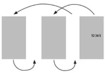
When tilling, leave approximately eight inches of untilled soil between the first and second tilling paths, then make the third path between the first and second, Figure 14.
In some soils, the desired depth is achieved the first time over the garden. In other soils, the desired depth is obtained by going over the garden two or three times. Passes
should be made across the length and width of the garden alternately. Rocks which are turned up should be removed from the garden area.
flowchart
graph TD
    A[" "] --> B[" "]
    B --> C[" "]
    C --> D["12345"]
    D --> A
    style A fill:#ccc,stroke:#333
    style B fill:#ccc,stroke:#333
    style C fill:#ccc,stroke:#333
    style D fill:#ccc,stroke:#333
Figure 14
Cultivating Procedures
For cultivating, a two to three inch depth is desirable. The tine width can be reduced to 13 inches by removing the outer tines completely from the tiller. See the Service section for instructions on removing the tines.
When laying out plant rows, be sure to allow enough width to permit cultivation between the rows. In growing corn or similar crops, check-row planting will permit cross cultivation and practically eliminate hand hoeing. See Figure 15.

natural_image
Diagram of a fluid or filtration system with repeating streams and bubbles (no text or symbols)Figure 15
SERVICE

WARNING
Disconnect the spark plug wire and ground it against the engine before performing any repairs.
Engine
Refer to the separate Engine Operator's Manual for engine maintenance instructions.
Tines
Clean the underside of the tine shield after each use. The dirt washes off the tines easier if rinsed off immediately instead of after it dries. Always towel dry the tiller afterwards and apply a light coat of oil or silicone to prevent rusting or water damage.
NOTE: Never use a pressure washer to clean your tiller. Water can penetrate tight areas of the tiller and its chain case and cause serious damage to machine.
Lubrication
Pivot Points
Remove the belt cover and lubricate all the pivot points and linkages at least once a season with light oil. Keep the belts free of lubrication.
Tine Shafts
Remove the tine assemblies and lubricate the tine shafts at least once a season.
Wheel Shafts
Remove the wheel assemblies and lubricate the axle shafts at least once a season.
Chain Drive
The chain drive is pre-lubricated and sealed at the factory.
Adjustments
Cable Adjustment
Refer to the Assembly & Set-Up section of this manual for instructions on adjusting the clutch cable.
Tines (Model 21B-34M8710)
With the outer tines installed, the working width of the machine is 24". This width may be expanded to 26" by removing the clevis and cotter pins, sliding each outer tine outward away from the center of the tiller and re-securing the pins in the holes provided. See Figure 16.
Tines (Models 21B-34M8766 & 21B-34M8793)
With the outer tines installed, the working width of the machine is 24". This width may be reduced to 22" by removing the clevis and cotter pins, sliding each outer tine inward toward the center of the tiller and re-securing the pins in the holes provided. See Figure 17.
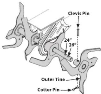
Figure 16
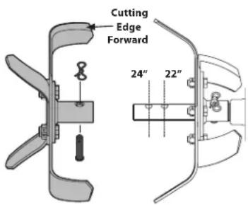
Figure 17
Tine Inspection (Models 21B-34M8766 & 21B-34M8793)
The bolo tines (if equipped) will wear with use and should be inspected at the beginning of each tilling season and after every 30 operating hours. The tines can be replaced either individually or as a complete set. See the Supplement Sheet for tine identification and part numbers.
With use, the tines will become shorter, narrower and pointed. Badly worn tines will result in a loss of tilling depth and reduced effectiveness when chopping up and turning under organic matter.
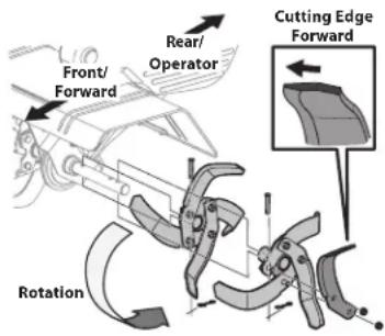
Figure 18
Refer to Figure 18 for the following tine procedures.
Removing/Installing a Single Tine
- With the engine shut off and the spark plug wire disconnected, remove the two hex screws (3/8-16 x 1.00) and hex lock nuts (3/8-16) that attach a single tine to a tine holder. If needed, use penetrating oil on the nuts.
- When installing a single tine, be sure to position it so that its cutting edge (sharp) will enter the soil first as the tiller moves forward.
Removing/Installing a Tine Assembly:
- A tine assembly consists of eight tines mounted on a tine holder.
- If removing both tine assemblies, mark them "left" and "right" before removal. Remove the hex screw (3/8-16 x 1.75) and flange lock nut (3/8-16) that secure the tine assembly to the tine shaft. If necessary, use a rubber mallet to tap the tine assembly outward off the shaft.
- Before reinstalling the tine assembly, inspect the tine shaft for rust, rough spots or burrs. Lightly file or sand, as needed. Apply a thin coat of grease to the shaft.
- Install each tine assembly so that the cutting (sharp) edge of the tines will enter the soil first when the tiller moves forward. Secure the tine assembly to the tine shaft using the screw and lock nut.
Off-Season Storage
If the tiller will not be used for a period longer than 30 days, the following steps should be taken to prepare the tiller for storage.
- Clean the exterior of the engine and the entire tiller thoroughly. Lubricate the tiller as described in the lubrication instructions.
- The use of pressure washers is not recommended for cleaning your tiller. They may cause damage to electric components, spindles, pulleys, bearings or the engine. The use of pressure washers will result in shortened life and reduce serviceability.
- Refer to the engine manual for correct engine storage instructions.
- Wipe tines with oiled rag to prevent rust.
- Store tiller in a clean, dry area. Do not store next to corrosive materials, such as fertilizer.
NOTE: When storing any type of power equipment in an unventilated area or metal storage shed, care should be taken to rustproof the equipment. Using a light oil or silicone, coat the equipment and especially any springs, bearings and cables.
SERVICE
Belt Replacement
Your tiller has been engineered with a belt made of special material (Kevlar Tensile) for longer life and better performance. It should not be replaced with an off-the-shelf belt. Order all belts through your authorized service dealer.
- Disconnect and ground the spark plug wire against the engine.
- Remove the belt cover from the left side of the tiller by removing the two hex washer screws and the lock nut and flat washer. See Figure 19.
- Remove the idler pulley bolt and move the belt from under the idler pulley keeper. See Figure 20.
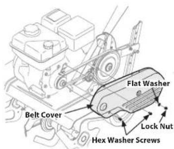
Figure 19
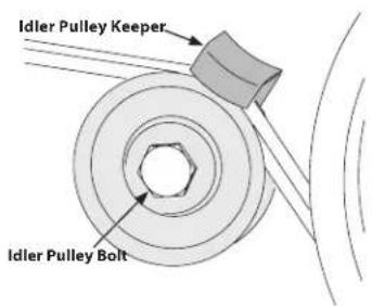
Figure 20
- Using a 1/2" wrench, remove the hex screw securing the belt keeper to the engine. See Figure 21.
- Remove the belt.
- When installing a new belt, or reinstalling the old, be sure to place the wider side of the belt away from the engine and transmission pulleys.
NOTE: Upon reassembly, make certain that the idler pulley keeper is as shown in Figure 22. Take note of the notch on the bottom of the keeper and the alignment when reassembling with the replacement belt.
NOTE: After re-installing the belt, double-check the cable adjustment. Refer to the Assembly & Set-Up section for instructions on adjusting the cable.
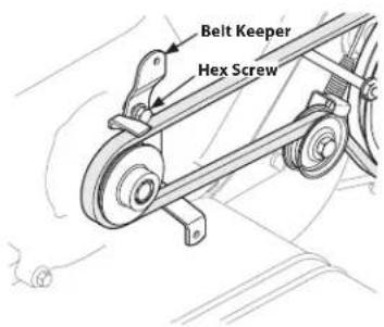
Figure 21
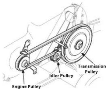
Figure 22
Troubleshooting
| Problem Cause Remedy | ||
| Tines do not engage 1. Foreign object lodged in tines | 2. Tine clevis pin(s) missing3. Pulley and idler not in correct adjustment4. Control cable not adjusted properly5. Belt worn and/or stretched | 1. Dislodge foreign object2. Replace tine clevis pin(s)3. Take tiller to authorized service dealer4. Adjust control cable5. Replace belt |
| Tines skip over ground | 1. Improper rotation | 1. Forward rotation should only be used on soil that has already been tilled, not on virgin soil |
| Wheels do not engage 1. Clevis pin missing | 2. Control cable not adjusted properly3. Belt worn and/or stretched | 1. Replace clevis pin2. Adjust control cable3. Replace belt |
NOTES
MANUAL DE OPERACIÓN
natural_image
Row of identical empty rectangular boxes with no text or symbolsNÚMERO DE SERIE

natural_image
Row of identical empty rectangular boxes with no text or symbolsÍndice
natural_image
Technical line drawing of a mechanical assembly with two wheels and mounting brackets (no text or symbols)Figura 3
natural_image
Technical line drawing of a mechanical assembly with levers and gears (no text or symbols)Figura 4
MONTAJE Y CONFIGURACION
Manija
natural_image
Diagram of a hand holding a tool with a ruler and multiple force arrows indicating movement (no text or labels)Figura 5
natural_image
Diagram of a mechanical clamp or tool with a curved blade and handle, no text or symbols presentFigura 6
natural_image
Technical diagram of a mechanical clamp or bracket assembly with an inset showing a close-up of the component (no text or symbols present)Figura 7
Ajustes

ADVERTENCIA
natural_image
Mechanical diagram showing a pulley system with weights and motion arrows (no text or symbols)Figura 8
natural_image
Technical line drawing of a mechanical tool with rotating components and a ruler (no text or symbols)Figura 11
natural_image
Technical line drawing of a mechanical assembly with rollers and a ruler (no text or symbols)Figura 12
natural_image
Technical illustration of a mechanical tool with a blade and rotor (no text or symbols)Figura 13
natural_image
Diagram of a fluid flow system with streamlines and bubbles, no text or symbols presentFigura 15
SERVICIO

ADVERTENCIA
- MODEL NUMBER
- SERIAL NUMBER
- Table of Contents
- WARNING
- California Proposition 65
- SAFE OPERATION PRACTICES
- DANGER
- Training
- Preparation
- Safe Handling of Gasoline:
- Operation
- Maintenance & Storage
- Notice Regarding Emissions
- Spark Arrestor
- Safety Symbols
- ASSEMBLY & SET-UP
- Thank You
- Contents of Carton
- Assembly
- Recommended Tools for Assembly
- Tines
- Wheel Assembly &
- Depth Stake Assembly
- Handle
- Adjustments
- Wheels
- Depth Stake
- Clutch Cable Adjustment
- Set-Up
- Gas & Oil Fill-Up
- Engine Controls
- Clutch Lever
- Handle Adjustment Crank
- Starting & Stopping the Engine
- Engaging the Drive & Tines
- Turning the Tiller
- Setting the Depth
- Wheel Yoke Forward
- Wheel Yoke to Back
- Handle Pressure
- Clearing the Tines
- Transporting & Storing the Tiller
- Using the Tiller
- Tilling Procedure
- Cultivating Procedures
- SERVICE
- Engine
- Lubrication
- Pivot Points
- Tine Shafts
- Wheel Shafts
- Chain Drive
- Cable Adjustment
- Tines (Model 21B-34M8710)
- Tines (Models 21B-34M8766 & 21B-34M8793)
- Tine Inspection (Models 21B-34M8766 & 21B-34M8793)
- Removing/Installing a Single Tine
- Removing/Installing a Tine Assembly:
- Off-Season Storage
- Belt Replacement
- NOTES
- MANUAL DE OPERACIÓN
- NÚMERO DE SERIE
- Índice
- MONTAJE Y CONFIGURACION
- Manija
- Ajustes
- ADVERTENCIA
- SERVICIO
Brand : Craftsman
Model : CMXGVAM1144043
Category : Rototiller