
CMXGVAM1144037 - Rototiller Craftsman - Free user manual and instructions
Find the device manual for free CMXGVAM1144037 Craftsman in PDF.


| Product Type | Rear Tine CRT Tiller (Counter-Rotating Tine) |
| Brand | Craftsman |
| Model | CMXGVAM1144037 |
| Engine | 4-stroke gasoline (refer to Engine Operator's Manual for specs) |
| Tine Type | Bolo tines, counter-rotating |
| Wheel Drive | Wheel drive pins (wheel drive or freewheel mode) |
| Forward Drive Control | Forward clutch bail |
| Reverse Drive Control | Reverse handle assembly (if equipped) |
| Depth Control | Depth regulator lever with notched height settings |
| Handlebar Height Adjustment | 3 settings to position at waist level |
| Tire Pressure | 15-20 PSI (both tires equal) |
| Transmission Oil | Synthetic 75W 140 |
| Fuel | Regular unleaded gasoline |
| Emergency Stop | Emergency stop control switch (if equipped) |
| Spark Arrestor | Available for muffler (required on some lands) |
| Lubrication Interval | Every 10 operating hours |
| Transmission Oil Check | Every 30 hours |
| Tine Inspection | At start of each season and every 30 hours |
| Belt Type | Factory-authorized drive belt (specific model) |
| Assembly Required | Yes (handlebar, clutch cables, emergency stop wire) |
| Intended Use | Garden tilling and cultivation |
| Safety Features | Read manual, guards, shields, emergency stop |
Frequently Asked Questions - CMXGVAM1144037 Craftsman
User questions about CMXGVAM1144037 Craftsman
0 question about this device. Answer the ones you know or ask your own.
Ask a new question about this device
Download the instructions for your Rototiller in PDF format for free! Find your manual CMXGVAM1144037 - Craftsman and take your electronic device back in hand. On this page are published all the documents necessary for the use of your device. CMXGVAM1144037 by Craftsman.
USER MANUAL CMXGVAM1144037 Craftsman
Rear Tine CRT Tiller
Record Product Information
Before setting up and operating your new equipment, please locate the model plate and record the information in the area provided to the right. The model plate contains the unit's model and serial numbers. This information will be necessary, should you seek technical support via our web site, Customer Support Department, or with a local authorized service dealer.
MODEL NUMBER

natural_image
Row of identical empty rectangular boxes with no text or symbolsSERIAL NUMBER

natural_image
Row of identical empty rectangular boxes with no text or symbolsTable of Contents
Safe Operation Practices 2
Assembly & Set-Up.... 4
Controls & Operation 7
Service....10
Troubleshooting....12
Español....13
Replacement Parts ...... See Separate Supplement
Warranty ...... See Separate Supplement
WARNING
Read and follow all safety rules and instructions in this manual before attempting to operate this machine. Failure to comply with these instructions may result in personal injury.
WARNING
California Proposition 65
Engine Exhaust, some of its constituents, and certain vehicle components contain or emit chemicals known to the State of California to cause cancer and birth defects.
NOTE: This Operator's Manual covers several models. Features may vary by model. Not all features in this manual are applicable to all models and the model depicted may differ from yours.
SAFE OPERATION PRACTICES
WARNING
This symbol points out important safety instructions which, if not followed, could endanger the personal safety and/or property of yourself and others. Read and follow all instructions in this manual before attempting to operate this machine. Failure to comply with these instructions may result in personal injury. When you see this symbol - HEED ITS WARNING!
DANGER
This machine was built to be operated according to the safe operation practices in this manual. As with any type of power equipment, carelessness or error on the part of the operator can result in serious injury. This machine is capable of amputating hands and feet and throwing debris. Failure to observe the following safety instructions could result in serious injury or death.
Training
- Read, understand and follow all instructions on the machine and in the manual(s) before attempting to assemble and operate. Keep this manual in a safe place for future and regular reference and for ordering replacement parts.
- Be familiar with all controls and their proper operation. Know how to stop the machine and disengage it quickly.
- Never allow children under 14 years of age to operate this machine. Children 14 and over should read and understand the instructions and safe operation practices in this manual and on the machine and be trained and supervised by an adult.
- Never allow adults to operate this machine without proper instruction.
- Keep the area of operation clear of all persons, particularly small children and pets. Stop machine if anyone enters the area.
Preparation
- Thoroughly inspect the area where the equipment is to be used. Remove all stones, sticks, wire and other foreign objects which could be tripped over and cause personal injury.
- Wear sturdy, rough-soled work shoes and close fitting slacks and shirt. Loose fitting clothes or jewelry can be caught in moving parts. Never operate this machine in bare feet or sandals.
- Disengage clutch levers and shift (if provided) into neutral ("N") before starting the engine.
- Never leave this machine unattended with the engine running.
- Never attempt to make any adjustments while engine is running, except where specifically recommended in the operator's manual.
Safe Handling of Gasoline:
- To avoid personal injury or property damage use extreme care in handling gasoline. Gasoline is extremely flammable and the vapors are explosive. Serious personal injury can occur when gasoline is spilled on yourself or your clothes which can ignite. Wash your skin and change clothes immediately.
- Use only an approved gasoline container.
- Never fill containers inside a vehicle or on a truck or trailer bed with a plastic liner. Always place containers on the ground away from your vehicle before filling.
- When practical, remove gas-powered equipment from the truck or trailer and refuel it on the ground. If this is not possible, then refuel such equipment on a trailer with a portable container, rather than from a gasoline dispenser nozzle.
- Keep the nozzle in contact with the rim of the fuel tank or container opening at all times until fueling is complete. Do not use a nozzle lock-open device.
- Extinguish all cigarettes, cigars, pipes and other sources of ignition.
- Never fuel machine indoors.
- Never remove gas cap or add fuel while the engine is hot or running. Allow engine to cool at least five minutes before refueling.
- Never over fill fuel tank. Fill tank to no more than 1/2 inch below bottom of filler neck to allow space for fuel expansion.
- Replace gasoline cap and tighten securely.
- If gasoline is spilled, wipe it off the engine and equipment. Move unit to another area. Wait five minutes before starting the engine.
- To reduce fire hazards, keep machine free of grass, leaves or other debris build-up. Clean up oil or fuel spillage and remove any fuel soaked debris.
- Never store the machine or fuel container inside where there is an open flame, spark or pilot light as on a water heater, space heater, furnace, clothes dryer or other gas appliances.
Operation
- Do not put hands or feet near rotating parts. Contact with the rotating parts can amputate hands and feet.
- Always wear safety glasses or safety goggles during operation and while performing an adjustment or repair to protect your eyes. Thrown objects which ricochet can cause serious injury to the eyes.
- For extended use of this product, hearing protection is required.
- Do not operate machine while under the influence of alcohol or drugs.
-
Never operate this machine without good visibility or light. Always be sure of your footing and keep a firm hold on the handles.
-
Keep bystanders away from the machine while it is in operation. Stop the machine if anyone enters the area.
- Be careful when tilling in hard ground. The tines may catch in the ground and propel the tiller forward. If this occurs, let go of the handle bars and do not restrain the machine.
- Exercise extreme caution when operating on or crossing gravel surfaces. Stay alert for hidden hazards or traffic. Do not carry passengers.
- Never operate the machine at high transport speeds on hard or slippery surfaces.
- Exercise caution to avoid slipping or falling.
- Look down and behind and use care when in reverse or pulling machine towards you.
- Start the engine according to the instructions found in this manual and keep feet well away from the tines at all times.
- After striking a foreign object, stop the engine, disconnect the spark plug wire and ground against the engine. Thoroughly inspect the machine for any damage. Repair the damage before starting and operating.
- Disengage all clutch levers (if fitted) and stop engine before you leave the operating position (behind the handles). Wait until the tines come to a complete stop before unclogging the tines or making any adjustments or inspections.
- Never run an engine indoors or in a poorly ventilated area. Engine exhaust contains carbon monoxide, an odorless and deadly gas.
- Muffler and engine become hot and can cause a burn. Do not touch.
- Use caution when tilling near fences, buildings and underground utilities. Rotating tines can cause property damage or personal injury.
- Do not overload machine capacity by attempting to till soil too deep at too fast of a rate.
- If the machine should start making an unusual noise or vibration, stop the engine, disconnect the spark plug wire and ground it against the engine. Inspect thoroughly for damage. Repair any damage before starting and operating.
- Keep all shields, guards and safety devices in place and operating properly.
- Never pick up or carry machine while the engine is running.
- Use only attachments and accessories approved by the manufacturer. Failure to do so can result in personal injury.
- If situations occur which are not covered in this manual, use care and good judgement. Contact Customer Support for assistance and the name of your nearest servicing dealer.
Maintenance & Storage
- Keep machine, attachments and accessories in safe working order.
- Allow a machine to cool at least five minutes before storing. Never tamper with safety devices. Check their proper operation regularly.
- Check bolts and screws for proper tightness at frequent intervals to keep the machine in safe working condition. Also, visually inspect machine for any damage.
- Before cleaning, repairing or inspecting, stop the engine and make certain the tines and all moving parts have stopped. Disconnect the spark plug wire and ground it against the engine to prevent unintended starting.
-
Do not change the engine governor settings or over-speed the engine. The governor controls the maximum safe operating speed of engine.
-
Maintain or replace safety and instruction labels, as necessary.
-
Follow this manual for safe loading, unloading, transporting and storage of this machine.
-
Always refer to the Operator's Manual for important details if the machine is to be stored for an extended period.
-
If the fuel tank has to be drained, do this outdoors.
-
Observe proper disposal laws and regulations for gas, oil, etc. to protect the environment.
-
According to the Consumer Products Safety Commission (CPSC) and the U.S. Environmental Protection Agency (EPA), this product has an Average Useful Life of seven (7) years, or 130 hours of operation. At the end of the Average Useful Life have the machine inspected annually by an authorized service dealer to ensure that all mechanical and safety systems are working properly and not worn excessively. Failure to do so can result in accidents, injuries or death.
SAFE OPERATION PRACTICES
Notice Regarding Emissions
Engines which are certified to comply with California and federal EPA emission regulations for SORE (Small Off Road Equipment) are certified to operate on regular unleaded gasoline, and may include the following emission control systems: Engine Modification (EM), Oxidizing Catalyst (OC), Secondary Air Injection (SAI) and Three Way Catalyst (TWC) if so equipped.
Spark Arrestor
WARNING
This machine is equipped with an internal combustion engine and should not be used on or near any unimproved forest-covered, brushcovered or grass-covered land unless the engine's exhaust system is equipped with a spark arrestor meeting applicable local or state laws (if any).
If a spark arrestor is used, it should be maintained in effective working order by the operator. In the State of California the above is required by law (Section 4442 of the California Public Resources Code). Other states may have similar laws. Federal laws apply on federal lands.
A spark arrestor for the muffler is available through your nearest engine authorized service dealer or contact the service department, P.O. Box 361131 Cleveland, Ohio 44136-0019.
Safety Symbols
This page depicts and describes safety symbols that may appear on this product. Read, understand and follow all instructions on the machine before attempting to assemble and operate.
| Symbol Description | |
 | READ THE OPERATOR'S MANUAL(S)Read, understand and follow all instructions in the manual(s) before attempting to assemble and operate. |
 | WARNING—ROTATING TINESDo not put hands or feet near rotating parts. Contact with the rotating parts can amputate hands and feet. |
WARNING
Your Responsibility — Restrict the use of this power machine to persons who read, understand and follow the warnings and instructions in this manual and on the machine. SAVE THESE INSTRUCTIONS!
ASSEMBLY & SET-UP
Thank You
Thank you for purchasing this product. It was carefully engineered to provide excellent performance when properly operated and maintained.
Please read this entire manual prior to operating the equipment. It instructs you how to safely and easily set up, operate and maintain your machine. Please be sure that you, and any other persons who will operate the machine, carefully follow the recommended safety practices at all times. Failure to do so could result in personal injury or property damage.
All information in this manual is relative to the most recent product information available at the time of printing. Review this manual frequently to familiarize yourself with the machine, its features and operation. Please be aware that this Operator's Manual may cover a range of product specifications for various models. Characteristics and features discussed and/or illustrated in this manual may not be applicable to all models. We reserve the right to change product specifications, designs and equipment without notice and without incurring obligation.
If applicable, the power testing information used to establish the power rating of the engine equipped on this machine can be found at www.opei.org or the engine manufacturer's web site.
If you have any problems or questions concerning the machine, phone an authorized service dealer or contact us directly. We want to ensure your complete satisfaction at all times.
Throughout this manual, all references to right and left side of the machine are observed from the operating position.
The engine manufacturer is responsible for all engine-related issues with regards to performance, power-rating, specifications, warranty and service. Please refer to the engine manufacturer's Owner's/Operator's Manual, packed separately with your machine, for more information.
Contents of Carton
• Tiller
- Bottle of Oil
- Handlebar Assembly
- Operator's Manual
• Engine Operator's Manual
NOTE: This Operator's Manual covers several garden tiller models. The tiller depicted may differ from yours.

WARNING
To prevent personal injury or property damage, do not start the engine until all assembly steps are complete and you have read and understand the safety and operating instructions in this manual.
Recommended Tools for Assembly
- Two 1/2'' open-end wrenches
- Block of wood (to support tiller when removing wheels)
- Tire pressure gauge
- Clean oil funnel
- Motor oil. Refer to the Engine Operator's Manual for oil specifications and quantity required.
Assembly
Unpacking Instructions
NOTE: While unpacking, do not severely bend any of the control cables.
- The tiller is heavy, do not attempt to remove it from the shipping platform until instructed to do so in these Assembly steps.
-
Remove any packaging material from the carton. Remove any staples from the bottom of the carton and remove the carton from the shipping platform.
-
Remove all loose parts from the carton. Check that you have the items listed in the Contents of Carton list (contact your local dealer or the factory if items are missing or damaged).
Handle
NOTE: All references to the right or left side of the tiller are from the operator's position.
- Remove two hex screws (5/16-18 x 1.50), two flange lock nuts (5/16-18), carriage bolt (5/16-18 x 6.75), belleville washer (.326 x .875 x .145) and knob (5/16-18) from the lower handlebar and support brackets. See Figure 1.
- Using two hex screws and two flange lock nuts, loosely attach the handlebar support using the upper holes. See Figure 2.
- Loosely attach the support brackets to the outside of the handlebar assembly using the carriage bolt, belleville washer and knob. See Figure 3.
NOTE: If a support bracket will not move, loosen the attaching hex screws (5/16-18 x .75) and flange lock nuts (5/16-18) at the base of the support brackets.
NOTE: The support brackets must be assembled to the outside of the handlebar assembly.
- There are three height adjustment holes in the handlebar support bracket. Use a setting that will position the handlebars at approximately waist level when the tines are 3-4" into the soil. To adjust the height of the handlebars loosen the knob on the handle, pull out on the carriage screw, adjust to the desired setting, push the carriage screw in until the square portion of the screw locks into place and re-tighten the knob. See Figure 4.
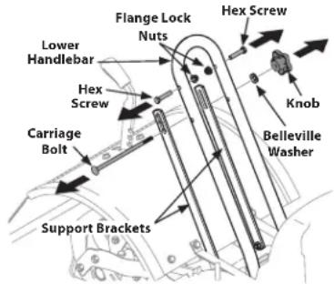
Figure 1
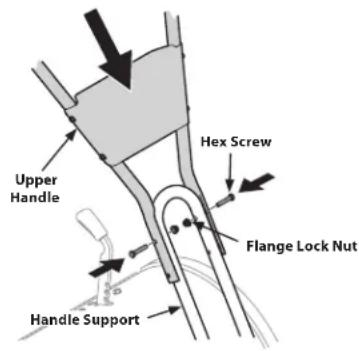
Figure 2
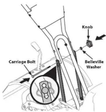
Figure 3
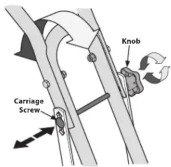
Figure 4
ASSEMBLY & SET-UP
- Tighten all the handlebar mounting hardware securely.
Attaching Clutch Cables
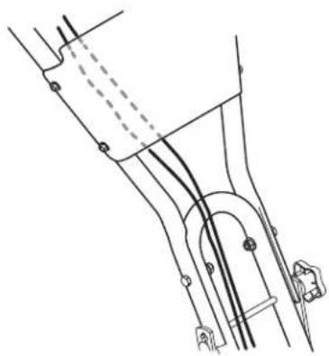
- Carefully unwrap the cable(s) from the shipping position. To attach the clutch cable(s), feed the cable(s) up the front of the lower right handle and behind the handle panel. See Figure 5.
- Pull the forward clutch cable with the black end fitting up through the bottom hole of the cable bracket and push the cable connector up through the hole until the groove in the connector snaps into place. See Figure 6.
- Place the Z-connector into the hole in the forward clutch bail from the outside of the bail to the inside. See Figure 6.
- Pull the reverse clutch cable (if equipped) with the red fitting up through the top hole of the cable bracket and push the cable connector up through the hole until the groove in the connector snaps into place. See Figure 7.
- Place the Z-connector into the hole in the reverse clutch handle assembly from the inside of the handle to the outside. See Figure 7.
Installing Emergency Stop Control (IF EQUIPPED)
natural_image
Technical line drawing of a mechanical assembly with no visible text or symbolsFigure 5
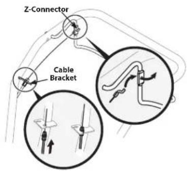
Figure 6
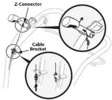
Figure 7
WARNING
Use extreme caution when reversing or pulling the machine towards you. To avoid getting pinned against a structure, ensure adequate distance before reversing near a wall or fence. For machines with powered reverse drive capability, familiarize yourself with the operation of the Emergency Stop Control. It provides a means of stopping power to the tines and wheel drive in an emergency situation.
-
Locate the emergency stop control wire on the right side of the unit behind the engine.
-
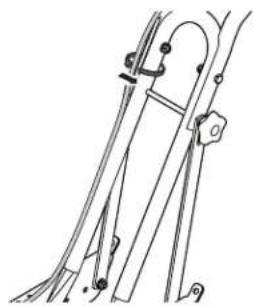
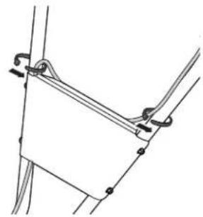
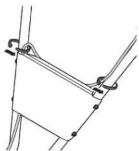
Route the emergency stop control wire up the outside on the right side lower handle support and right side handle support bracket. Secure the wire to the handle and support with a cable tie, slightly above the support bracket. See Figure 8.
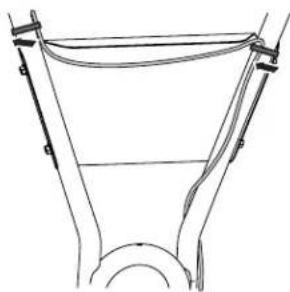
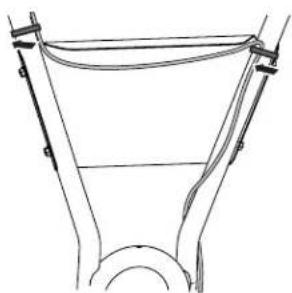
- Route the wire over the upper handle, then behind the handle panel, securing it to the right side of the handlebar with the clutch cables at the upper corner of the panel. See Figure 9.
- Route the wire behind the panel to the left side handle, and secure it just above the upper corner of the panel with a cable tie. (Keep the wire positioned along the inside of the handle). See Figure 10.
- Mount the emergency stop control ON/OFF switch onto the left side of the handlebar with the #10-32 : 1.50 hex bolt and 10-32 flange lock nut. See 1 in Figure 11.
- Secure the wire near the bottom of the handlebar with a cable tie looped through the hole beside the instruction label on the left handlebar. See 2 in Figure 11.
NOTE: Do not allow the wire to cover the safety label attached to the handle. Label must be fully visible and legible.
natural_image
Technical line drawing of a mechanical linkage or support structure (no text or symbols)Figure 8
natural_image
Pure mechanical linkage diagram without any text, numbers, or symbolsFigure 9
natural_image
Technical line drawing of a mechanical component with no visible text or symbolsFigure 10
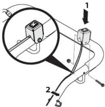
Figure 11
Move Tiller Off Crate
To roll the tiller off the shipping platform, put the wheels in freewheel, as follows:
- Place a sturdy block under the transmission to raise one wheel about 1" off the ground.
- Remove the wheel drive pin from the wheel hub and wheel shaft. See Figure 12.
- Slide the wheel fully inward on the wheel shaft. Reinstall the wheel drive pin through the wheel shaft only (not through the
wheel hub). See Figure 12. The wheel should now spin freely (freewheel) on the wheel shaft. Repeat with the other wheel.
- Use the handlebar to roll the tiller to a flat area.
NOTE: Before starting the engine, the wheels must be placed in the WHEEL DRIVE position (pins through wheel hubs and wheel shaft).
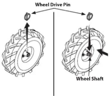
Figure 12
Set-Up
Tire Pressure
Check the air pressure with a tire gauge. Deflate or inflate the tires equally to between 15 and 20 PSI.
NOTE: Be sure that both tires are inflated equally or the tiller will pull to one side.
Gas & Oil Fill Up
WARNING
Use extreme care when handling gasoline. Gasoline is extremely flammable and the vapors are explosive. Never fuel the machine indoors or while the engine is hot or running. Extinguish cigarettes, cigars, pipes and any other sources of ignition.
Service the engine with gasoline and oil as instructed in the Engine Operator's Manual packed separately with your tiller. Read the instructions carefully.
Figure 13
NOTE: This Operator's Manual covers several garden tiller models. The tiller depicted may differ from yours.
Engine Controls
For detailed information on all engine controls refer to the separate Engine Operator's Manual.
Wheel Drive Pins
Each wheel is equipped with a wheel drive click pin that secures the wheel to the wheel shaft. The wheels can be positioned in either a wheel drive or a freewheel mode.
Forward Clutch Bail
The forward clutch bail controls the engagement of the forward drive of the wheels and tines.
Reverse Handle Assembly (IF EQUIPPED)
The reverse handle assembly controls the engagement of the reverse drive of the wheels and tines.
Depth Regulator Lever
This lever controls the tilling depth of the tines. Pull the lever back and slide it up or down to engage the notched height settings.
Handlebar Height Adjustment
The handlebar height is adjustable to three different settings. In general, adjust the handlebars so they are at waist level when the tines are 3-4" in the ground.
Emergency Stop Control (IF EQUIPPED)
The emergency stop control is a switch used to stop the tiller engine and tiller functions from the operator's position in emergency situations.
NOTE: Some engine models may also come equipped with an ignition ON/OFF switch. Consult the separate Engine Operator's Manual.
WARNING
Before operating your machine, carefully read and understand this manual and all of its safety, operating and maintenance sections and instructions, along with all of the decals on the machine. Failure to follow these instructions can result in serious personal injury.
Introduction
Read this entire section and the Engine Operator's Manual before you start the engine. Then, take the time to familiarize yourself with the basic operation of the tiller before using it in the garden.
Find an open, level area and practice using the tiller controls without the tines engaging the soil (put tines in "transport" setting).
Only after you've become completely familiar with the tiller should you begin using it in the garden.
Break-In Operation
Perform the following maintenance after the first five (5) hours of new operation.
-
Change engine oil.
-
Check for loose or missing hardware on the tiller. Tighten or replace as needed.
- Check transmission gear oil level. See the Service section.
Starting the Engine
Pre-Start Checklist
With the spark plug wire disconnected from the spark plug, perform the following checks and services before each use:
- Read the Safe Operation Practices and the Controls & Operation sections in this manual. Read the separate Engine Operator's Manual provided with the tiller.
- Put the wheels in the WHEEL DRIVE position (wheel pins must be through holes in wheel hubs and wheel shaft).
WARNING
Never allow either of the wheels to be in the freewheel position when the engine is running. Always put both wheels in the wheel drive position before starting the engine. Failure to comply could cause loss of tiller control, property damage or personal injury.
- Check the tiller for loose or missing hardware. Service as required.
- Check the engine oil level to ensure properly filled. See the Engine Operator's Manual.
- Check that all the safety guards and covers are in place.
- Check the air cleaner and engine cooling system. See the Engine Operator's Manual.
- Fill the fuel tank with gasoline according to the directions in the separate Engine Operator's Manual. Follow all instructions and safety rules carefully.
- If necessary, attach the spark plug wire to the spark plug.
To help prevent serious personal injury or damage to equipment, put both wheels in the WHEEL DRIVE position. Never have wheels in FREEWHEEL position when the engine is running. When the wheels are in FREEWHEEL, they do not hold back the tiller and the tines could propel the tiller rapidly forward or backward. Put the Forward Clutch Bail in neutral (disengaged) position by releasing the lever.

WARNING
Never run the engine indoors or in an enclosed, poorly ventilated area. Engine exhaust contains carbon monoxide, an odorless and deadly gas. Avoid the engine muffler and nearby areas. Temperatures in these areas may exceed 150^ F.
- Complete the Pre-Start Checklist in this section.
- Put the wheels in the WHEEL DRIVE position.
- Move the depth regulator lever all the way down to the "travel" position, so that the tines clear the ground. To change the depth setting, pull back on the depth regulator lever (A) and lift up or down (B), then release the lever (C) to secure in the desired position. See Figure 14.
- Release all of the controls on the tiller.
-
If equipped with an emergency stop control switch, make sure that the emergency stop control is set to the ON position, represented by the solid line while attempting to start the engine. See Figur
-
Start the engine as instructed in the Engine Operator's Manual.
IMPORTANT: If equipped with an emergency stop control switch, verify the stop control function works properly before each use by moving the switch to the OFF position with the engine running. Only continue operation if the emergency stop control switch stops the engine.
Stopping the Engine
- To stop the wheels and tines, release the Forward Clutch Bail.
- Refer to the Engine Operator's Manual for instructions on stopping the engine.
Using Emergency Stop Control (If Equipped)
To stop the running engine using the emergency stop control, move the switch to the OFF position, represented by the circle. See Figure 15.
Engage Drive & Tines
- For forward motion of the wheels and power to the tines pull the Forward Clutch Bail up against the handlebar. Release the bail to stop the forward motion of the wheels and tines.
- When tilling, relax and let the wheels pull the machine while the tines dig. Walk behind and a little to one side of the tiller. Use one hand, yet keep a light — but secure — grip on the handlebar (while keeping your arm loose). See Figure 16. Let the tiller move at its own pace and
do not push down on the ha this takes weight off the wh
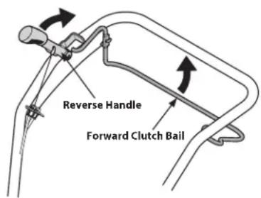
Figure 16
do not push down on the handlebars to try and force the tines to dig deeper — this takes weight off the wheels and reduces traction.

WARNING
Do not push down on the handlebars to try to make the tiller till more deeply. This prevents the wheels from holding the tiller back and can allow the tines to rapidly propel the tiller forward, which could result in loss of control, property damage or personal injury.
- To move in reverse:
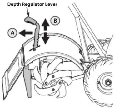
Figure 14
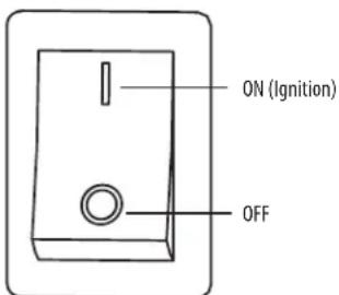
Figure 15
- Look behind and exercise caution when operating in reverse. Do not till while in reverse.
- Stop all forward motion. Lift the handlebar with one hand until the tines are off the ground and then pull the Reverse Handle back. To stop reversing, let go of the Reverse Handle.
- If longer distances need to be covered in reverse, shut off the engine, then place the two wheels in freewheel.
b. On models without reverse handle:
- Release the forward clutch bail. Then lift the handlebar until the tines are off the ground.
- Swing the handlebar to the left so the right wheel takes a "step" backward. Next swing the handlebar to the right so the left wheel "steps" backward. Repeat as needed.
- If longer distances need to be covered in reverse, shut off the engine, then place the two wheels in freewheel.
Practice turning the tiller in a level, open area. Be very careful to keep your feet and legs away from the tines.
- To begin a turn, lift the handlebars until the tines are out of the ground and the engine and tines are balanced over the wheels. See Figure 17.
- With the tiller balanced, push sideways on the handlebar to steer in the direction of the turn. See Figure 17.
- After turning, slowly lower the tines into the soil to resume tilling. See Figure 17.
Clearing the Tines
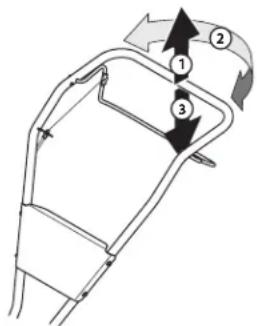
Figure 17
WARNING
Before clearing the tines by hand, stop the engine, allow all moving parts to stop and disconnect the spark plug wire. Failure to follow this warning could result in personal injury.
The tines have a self-clearing action which eliminates most of the debris. However, occasionally debris may become tangled. Follow these procedures to help avoid tangling and to clean the tines, if necessary.
- Try to till under crop residues or cover crops while they are green, moist and tender.
- While tilling, try swaying the handlebars from side to side (about 6" to 12"). This "fishtailing" action often clears the tines of debris.
Tilling Tips & Techniques
Tilling Depth
WARNING
Before tilling, contact your telephone or utilities company and inquire if underground equipment or lines are used on your property. Do not till near buried electric cables, telephone lines, pipes or hoses.
- This is a CRT (counter-rotating tine) tiller. As the wheels pull forward, the tines rotate backward. This creates an "uppercut" tine action which digs deeply, uprooting soil and weeds. Don't overload the engine, but dig as deeply as possible on each pass. On later passes, the wheels may tend to spin in the soft dirt. Help them along by lifting up slightly on the handlebar (one hand, palm up, works most easily).
- Avoid the temptation to push down on the handlebars in an attempt to force the tiller to dig deeper. Doing so takes the weight off the powered wheels, causing them to lose traction. Without the wheels to hold the tiller back, the tines will attempt to propel the tiller backward, towards the operator.
- When cultivating
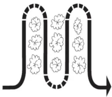
(breaking up surface soil around plants to destroy weeds, see Figure 18), adjust the tines to dig only 1" to 2" deep. Using shallow tilling depths helps prevent injury to the plants whose roots often grow close to the surface. If needed, lift up on the handlebars slightly to prevent the tines from
natural_image
Diagram of a U-shaped pipe with floral patterns inside, indicating fluid flow or particle distribution (no text or symbols)Figure 18
digging too deeply. (Cultivating on a regular basis not only eliminates weeds, it also loosens and aerates the soil for better moisture absorption and faster plant growth.) Watering the garden area a few days prior to tilling will make tilling easier, as will letting the newly worked soil set for a day or two before making a final, deep tilling pass.
Loading & Unloading the Tiller
WARNING
Loading and unloading the tiller into a vehicle is potentially hazardous and doing so is not recommended unless absolutely necessary, as this could result in personal injury or property damage.
If it is necessary to load or unload the tiller, follow these guidelines.
- Stop the engine, wait for all parts to stop moving, disconnect the spark plug wire and let the engine and muffler cool.
- The tiller is too heavy and bulky to be lifted safely by one person. Two or more people should share the load.
- Use sturdy ramps and manually — with the engine shut off — roll the tiller into and out of the vehicle. Two or more people are needed to do this.
- The ramps must be strong enough to support the combined weight of the tiller and any handlers. The ramps should provide good traction to prevent slipping, they should have side rails to guide the tiller along the ramps and they should have a locking device to secure them to the vehicle.
- The handlers should wear sturdy footwear that will help prevent slipping.
- Position the loading vehicle so that the ramp angle is as flat as possible (the less incline to the ramp, the better). Turn the vehicle's engine off and apply its parking brake.
- When going up ramps, stand in the normal operating position and push the tiller ahead of you. Have a person at each side to turn the wheels.
- When going down ramps, walk backward with the tiller following you. Keep alert for any obstacles behind you. Position a person at each wheel to control the speed of the tiller. Never go down ramps tiller-first, as the tiller could tip forward.
- Place wooden blocks on the downhill side of the wheels if you need to stop the tiller from rolling down the ramp. Also, use the blocks to temporarily keep the tiller in place on the ramps (if necessary), and to chock the wheels in place after the tiller is in the vehicle.
- After loading the tiller, prevent it from rolling by engaging the wheels in the wheel drive position. Chock the wheels with blocks and securely tie the tiller down.
SERVICE

WARNING
Before inspecting, cleaning or servicing the machine, shut off the engine, wait for all moving parts to come to a complete stop, wait for the engine to cool, disconnect the spark plug wire and move the wire away from the spark plug. Failure to follow these instructions can result in serious personal injury or property damage.
Maintenance
Engine
Refer to the Engine Operator's Manual packed with your tiller for all engine maintenance.
Tire Pressure
Check the air pressure in both tires. The air pressure should be between 15-20 PSI. Keep both tires equally inflated to help prevent machine from pulling to one side.
Hardware
Check for loose or missing hardware after every 10 operating hours and tighten or replace (as needed) before using tiller.
Be sure to check the screws underneath the tiller hood that secure the transmission cover and the Depth Regulator Lever to the transmission.
Lubrication
After every 10 operating hours, oil or grease the lubrication points shown in Figure 19.
Use a clean lubricating oil (#30 weight motor oil is suitable) and a clean general purpose grease (grease containing a metal lubricant is preferred, if available).
- Remove the wheels, clean the wheel shaft and apply a thin coating of grease to the wheel shaft.
- Grease the back, front and sides of the depth regulator lever.
- Remove the tines and clean the tine shaft. Use a file or sandpaper to gently remove any rust, burrs or rough spots (especially around holes in the shaft). Apply grease to the ends of the shaft before installing the tines.
- Oil the threads on the handlebar height adjustment screws and the handlebar attaching screws.
Transmission Gear Oil
Check the transmission gear oil after every 30 hours of operation or whenever you notice any oil leak. Operating the tiller when the transmission is low on oil can result in severe damage.
To Check the Transmission Gear Oil Level:
- Check the gear oil level when the transmission is cool. Gear oil will expand in warm operating temperatures and this expansion will provide an incorrect oil level reading.
- With the tiller on level ground, pull the Depth Regulator Lever all the way up.
- Clean the area around the oil fill plug. See Figure 20.
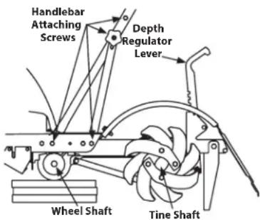
Figure 19
- Remove the oil fill plug from the transmission housing and look inside the oil fill hole to locate the main drive shaft situated below the hole. See Figure 20.
- The gear oil level is correct if the gear oil is approximately halfway up the side of the main drive shaft.
- If the gear oil level is low, add gear oil as described next. If the gear oil level is okay, securely replace the oil fill plug.
- When adding gear oil, use Synthetic 75W 140.
- While checking frequently to avoid overfilling, slowly add gear oil into the oil fill hole until it reaches the halfway point on the drive shaft.
- Securely replace the oil fill plug.
Off-Season Storage
When the tiller won't be used for an extended period, prepare it for storage as follows:
- Clean the tiller and engine.
- Do routine tiller lubrication and check for loose parts and hardware.
- Protect the engine and perform recommended engine maintenance by following the storage instructions found in the Engine Operator's Manual. Be sure to protect the fuel lines, carburetor and fuel tank from gum deposits by removing fuel or by treating fuel with a fuel stabilizer (follow the engine manufacturer's recommendations).
- Store the tiller in a clean, dry area.
- Never store the tiller with fuel in the fuel tank in an enclosed area where gas fumes could reach an open flame or spark, or where ignition sources are present (space heaters, hot water heaters, furnaces, etc.).
Belt Replacement
If the drive belt or reverse drive belt needs to be replaced, see your local authorized dealer or refer to the separate supplement for ordering information. Use only a factory-authorized belt as an "over-the-counter" belt may not perform satisfactorily. The procedure requires average mechanical ability and commonly available tools.
NOTE: When reinstalling the belt cover, be sure to engage the bail and hold it so that the drive belt is tight before attempting to reinstall the belt cover. This will enable the belt to fall under the belt keeping mechanism built into the belt cover. Failure to do so could damage the belt and/or belt cover.
Tines
The bolo tines will wear with use and should be inspected at the beginning of each tilling season and after every 30 operating hours. The tines can be replaced either individually or as a complete set. See the separate supplement for tine identification and part numbers.
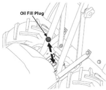
Figure 20
SERVICE
Tine Inspection
With use, the tines will become shorter, narrower and pointed. Badly worn tines will result in a loss of tilling depth, and reduced effectiveness when chopping up and turning under organic matter.
Refer to Figure 21 for the following tine procedures.
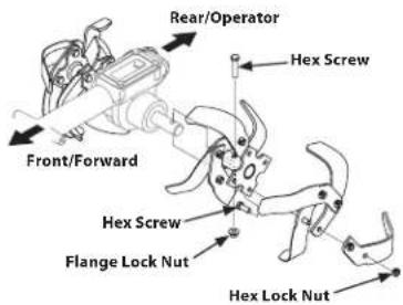
Figure 21
Removing/Installing a Single Tine
- With the engine shut off and the spark plug wire disconnected, remove the two hex screws (3/8-16 x 1.00) and hex lock nuts (3/8-16) that attach a single tine to a tine holder. If needed, use penetrating oil on the nuts.
- When installing a single tine, be sure to position it so that its cutting edge (sharp) will enter the soil first as the tiller moves forward.
Removing/Installing a Tine Assembly:
- A tine assembly consists of eight tines mounted on a tine holder.
- If removing both tine assemblies, mark them "left" and "right" before removal. Remove the hex screw (3/8-16 x 1.75) and flange lock nut (3/8-16) that secure the tine assembly to the tine shaft. If necessary, use a rubber mallet to tap the tine assembly outward off the shaft.
- Before reinstalling the tine assembly, inspect the tine shaft for rust, rough spots or burrs. Lightly file or sand, as needed. Apply a thin coat of grease to the shaft.
- Install each tine assembly so that the cutting (sharp) edge of the tines will enter the soil first when the tiller moves forward. Secure the tine assembly to the tine shaft using the screw and locknut.
Change Transmission Gear Oil
NOTE: The transmission gear oil does not need to be changed unless it has been contaminated with dirt, sand or metal particles.
- Drain the gasoline from the fuel tank or run the engine until the fuel tank is empty.
- Drain the oil from the engine.
- Remove the hex washer screw (1/4-20 x .500) and flat washer (.28 x .74 x .500) from the left side of the belt cover (if so equipped) and the hex washer screw (1/4-20 x .500) from the right side of the belt cover. Remove the belt cover. See Figure 22.
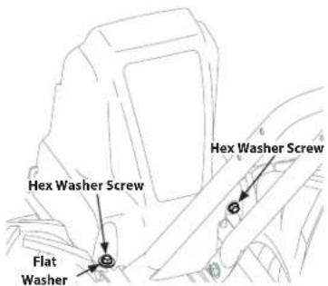
Figure 22
- Remove all dirt and clean the area around the transmission cover. See Figure 23.
- Remove the four hex screws (5/16-18 x .75) securing the transmission cover to the drive shaft and remove the cover. See Figure 23.
-
Remove the left-side wheel. Tilt the left-side wheel shaft into a drain pan and allow the gear
-
Reinstall the wheel and reinstall the transmission cover.
- Refill the transmission using Synthetic 75W 140. Refill the engine with motor oil and replenish the fuel tank with gasoline.
- Reinstall the belt cover.
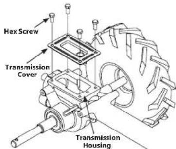
Figure 23
TROUBLESHOOTING
| Problem Cause Remedy | ||
| Wheels/tines will not turn 1. Improper use of controls. | 2. Worn, broken or mis-adjusted drive belt(s).3. Internal transmission wear or damage.4. Bolt loose in transmission pulley. | 1. Review Controls & Operation section.2. Replace or adjust belts.3. Contact local authorized dealer.4. Tighten bolt. |
| Tines turn, but wheels don’t | 1. Wheel Drive Pins not in WHEEL DRIVE.2. Bolt loose in transmission pulley.3. Internal transmission wear or damage. | 1. Insert Drive Pins properly.2. Tighten bolt.3. Contact local authorized dealer. |
| Wheels turn, but tines don’t | 1. Tine holder mounting hardware missing.2. Bolt loose in transmission pulley.3. Internal transmission wear or damage. | 1. Replace hardware.2. Tighten bolt.3. Contact local authorized dealer. |
| Poor tilling performance 1. Worn tines. | 2. Improper Depth Regulator setting.3. Forward Drive Belt slipping. | 1. Replace Tines.2. See “Tilling Tips & Techniques.”3. See Service section. |
MANUAL DEL OPERADOR
natural_image
Row of identical empty rectangular boxes with no text or symbolsNÚMERO DE SERIE

natural_image
Row of identical empty rectangular boxes with no text or symbolsTable of Contents
natural_image
Technical line drawing of a mechanical assembly with no visible text or symbolsFigura 5
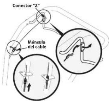
Figura 6
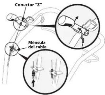
Figura 7
natural_image
Technical line drawing of a mechanical linkage or support structure (no text or symbols)Figura 8
natural_image
Pure mechanical linkage diagram without any text, numbers, or symbolsFigura 9
natural_image
Pure technical line drawing of a mechanical component without any text, numbers, or symbolsFigura 10
Figura 11
Figura 14
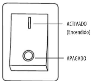
Figura 17
natural_image
Diagram of a fluid system with two parallel channels and floating particles, no text or symbols presentFigura 18
- Rear Tine CRT Tiller
- Record Product Information
- MODEL NUMBER
- SERIAL NUMBER
- Table of Contents
- WARNING
- SAFE OPERATION PRACTICES
- DANGER
- Training
- Preparation
- Safe Handling of Gasoline:
- Operation
- Maintenance & Storage
- Notice Regarding Emissions
- Spark Arrestor
- Safety Symbols
- ASSEMBLY & SET-UP
- Thank You
- Contents of Carton
- Recommended Tools for Assembly
- Assembly
- Unpacking Instructions
- Handle
- Attaching Clutch Cables
- Installing Emergency Stop Control (IF EQUIPPED)
- Move Tiller Off Crate
- Set-Up
- Tire Pressure
- Gas & Oil Fill Up
- Engine Controls
- Wheel Drive Pins
- Forward Clutch Bail
- Reverse Handle Assembly (IF EQUIPPED)
- Depth Regulator Lever
- Handlebar Height Adjustment
- Emergency Stop Control (IF EQUIPPED)
- Introduction
- Break-In Operation
- Starting the Engine
- Pre-Start Checklist
- Stopping the Engine
- Using Emergency Stop Control (If Equipped)
- Engage Drive & Tines
- Clearing the Tines
- Tilling Tips & Techniques
- Tilling Depth
- Loading & Unloading the Tiller
- SERVICE
- Maintenance
- Engine
- Hardware
- Lubrication
- Transmission Gear Oil
- Off-Season Storage
- Belt Replacement
- Tines
- Tine Inspection
- Removing/Installing a Single Tine
- Removing/Installing a Tine Assembly:
- Change Transmission Gear Oil
- TROUBLESHOOTING
- MANUAL DEL OPERADOR
- NÚMERO DE SERIE
Brand : Craftsman
Model : CMXGVAM1144037
Category : Rototiller