
CMXZDCG4910 - Garage door opener Craftsman - Free user manual and instructions
Find the device manual for free CMXZDCG4910 Craftsman in PDF.


| Product Type | Garage Door Opener |
| Brand | Craftsman |
| Model | CMXZDCG4910 |
| Drive Type | Belt Drive |
| Rail Length | 10 ft (3.05 m) |
| Power Source | 120V AC, 60 Hz |
| Motor Power | 1/2 HP |
| Motor Type | DC Motor |
| Lighting | Built-in light |
| Safety Features | Auto-reverse safety system, manual emergency release |
| Control Type | Wall console and remote control |
| Compatible Door Type | Standard sectional garage doors |
| Max Door Height | 7 ft (standard) |
| Weight (approx.) | 30 lbs (13.6 kg) |
| Dimensions (Rail Assembly) | 10 ft x 2 in x 3 in |
| Maintenance | Lubricate belt, check tension monthly; test safety reversal monthly |
| Cleaning | Wipe with damp cloth; do not use solvents |
| Replacement Parts | Belt Assembly (041A5250-2), Rope (041A3021), Master Link Kit (004A1008), Hanging Bracket |
| Repairability | User-serviceable belt and linkages; motor service by professional |
| Warranty | Limited lifetime on motor and belt (typical) |
Frequently Asked Questions - CMXZDCG4910 Craftsman
User questions about CMXZDCG4910 Craftsman
0 question about this device. Answer the ones you know or ask your own.
Ask a new question about this device
Download the instructions for your Garage door opener in PDF format for free! Find your manual CMXZDCG4910 - Craftsman and take your electronic device back in hand. On this page are published all the documents necessary for the use of your device. CMXZDCG4910 by Craftsman.
USER MANUAL CMXZDCG4910 Craftsman
- The trolley must be in down (closed door) position during assembly and installation. If you have a completely installed garage door opener, the rail/opener assembly must be taken down. The UP and DOWN travel must be readjusted after installation.
- Opener hanging brackets will require repositioning and the addition of an extra bracket for stability due to increased rail length.
• This may require two people for installation.
IF THIS IS A NEW INSTALLATION:
Use the front (header), belt assembly, and longer emergency release rope in this kit in place of those packaged with your garage door opener. Add the enclosed center rail as the second rail (remove one of the center rails packaged with the garage door opener) section, creating a five piece rail assembly. Complete the assembly, installation, and adjustment of the opener according to the garage door opener manual. Ensure that an additional hanging bracket is added for stability, as detailed below.
IF THIS IS AN EXISTING INSTALLATION, CONTINUE AS FOLLOWS:
- Pull down on the emergency release handle, then disconnect the trolley from the door arm.
- Disconnect the rail/opener assembly from the header bracket and hanging brackets, and place it on the floor.
- Remove the sprocket cover from the opener sprocket and set aside.
- Disconnect the master link from the trolley threaded shaft and belt; discard (Figure 1).
- Remove the spring/nut from the trolley and discard.
- Remove idler pulley assembly and set aside.
- Remove the belt assembly and discard.
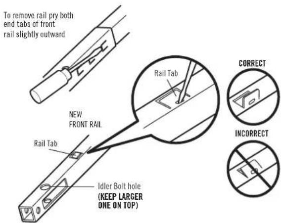
- Push the trolley back toward the opener. Disconnect the front rail and second rail sections by using a screwdriver tip to pry up the outer tab on each side of the rail, then slide it off the existing rail assembly. Discard the front and second rails (Figure 2).
- Align the new front and center rails with the existing rail assembly, keeping the cut out "window" at the front (header) end. Be sure to keep rails right side up: the idler pulley bolt hole above the window is larger on top of the rail than on the bottom. Slide the new center rail onto the assembly, then add the front rail. Tabs along the side will lock into place.
- As a temporary stop, insert a screwdriver into the hole 10" (25 cm) from the front end of the rail (Figure 1). Slide the trolley assembly to this point.
- Lay the new belt beside the rail. Grasp the end with the hooked trolley connector and pass approximately 12" (30 cm) of belt through the window. Keeping the ribbed side toward the rail, and allow it to hang while you complete the next two steps.
- Replace the idler pulley, lock washer and nut. Rotate it to be sure it spins freely. Grease the center if necessary.
- Locate the rail tab. Use a flathead screwdriver and lift the rail tab until the tab is vertical (90°) (Figure 2).
- Pull the belt around the idler pulley and hook the trolley connector into the retaining slot on the trolley (Figure 1). The ribbed side must contact the pulley.
- With the trolley against the screwdriver, dispense the remainder of the belt along the rail length toward the motor unit and around the sprocket (Figure 1). The sprocket teeth must engage the belt.
- Check to make sure the belt is not twisted, then connect it to the flat end of the trolley threaded shaft with the master link (Figure 1):
- Push pins of master link bar through holes in end of belt and trolley threaded shaft.
- Push master link cap over pins and past pin notches.
- Slide clip-on spring over cap and onto pin notches until both pins are securely locked in place.
WARNING
REFER TO GARAGE DOOR OPENER MANUAL FOR DETAILED INSTALLATION, ADJUSTMENTS, AND SAFETY INFORMATION.
To prevent possible SERIOUS INJURY or DEATH:
- Disconnect ALL electric and battery power BEFORE performing ANY service or maintenance.
CAUTION
The garage door MUST be in the fully closed position during installation.

WARNING: This product can expose you to chemicals including lead, which are known to the State of California to cause cancer or birth defects or other reproductive harm. For more information go to www.P65Warnings.ca.gov.
Figure 1
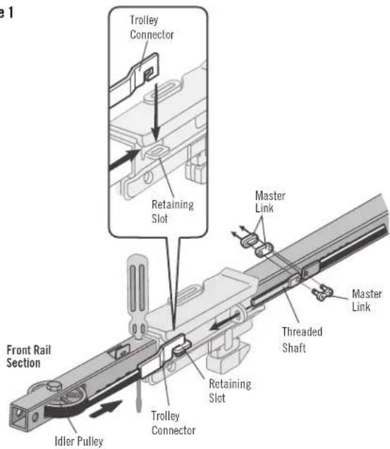
Figure 2
- Insert the trolley threaded shaft through the hole in the trolley. Be sure the belt is not twisted, and the ribbed side faces the rail.
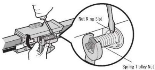
- Hold the belt at the trolley shaft as you thread the spring nut by hand (Figure 3) onto the shaft until finger tight against the trolley. Do not use any tools.
- Remove the screwdriver.
- Insert a flathead screwdriver tip into one of the nut ring slots and brace it firmly against the trolley.
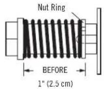
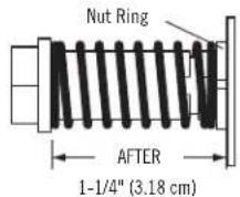
- Tighten the spring trolley nut with an adjustable wrench or a 7/16" open end wrench about a quarter turn until the spring releases and snaps the nut ring against the trolley. This sets the spring to optimum belt tension (Figure 3).
- Replace the sprocket cover. Refer to your garage door opener manual to complete the assembly, re-installation and adjustment of your opener. NOTE: Before hanging the opener, an additional hanging bracket is necessary for stability.
- Replace the old emergency release rope with the new, longer replacement rope.
- Reconnect power.
- Make adjustments and test the safety reversal system according to your garage door opener manual.
Figure 3
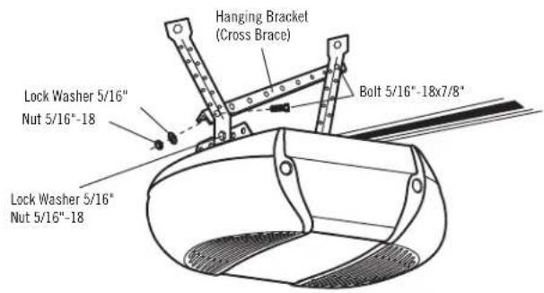
ADDING AN ADDITIONAL HANGING BRACKET:
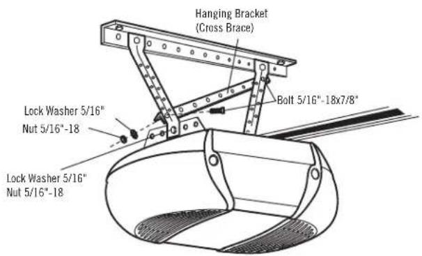
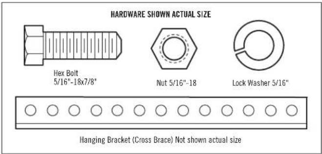
Cut the enclosed hanging bracket (cross brace) to fit across the installed hanging brackets. Fasten the cross brace to the top and bottom hole of the hanging brackets using 5/16" -18x7/8" hex bolts, 5/16 lock washers and 5/16"-18 nuts.
Unfinished Ceiling
Finished Ceiling
WARNING
To avoid possible SERIOUS INJURY from a falling garage door opener, fasten it SECURELY to structural supports of the garage. Concrete anchors MUST be used if installing any brackets into masonry.
REPLACEMENT PARTS
Part No. Description Qty
041A5250-2 10' Belt Assembly 1
041A3021 Rope
004A1008 Master Link Kit 1
1
CRAFTSMAN®
ANTES DE COMENZAR:
natural_image
Simple diagram of 12 circles arranged in two rows (no text or symbols)Brand : Craftsman
Model : CMXZDCG4910
Category : Garage door opener