
MS860 - Barcode scanners Unitech - Free user manual and instructions
Find the device manual for free MS860 Unitech in PDF.


| Product Type | Wireless Laser Barcode Scanner |
| Brand | Unitech |
| Model | MS860 |
| Dimensions (Scanner) | 126 x 83 x 143 mm (5 x 3.25 x 5.625 in) |
| Weight (Scanner) | 312 g (11 oz) |
| Dimensions (Cradle) | 206 x 97 x 57 mm (8.125 x 3.8125 x 2.25 in) |
| Weight (Cradle) | 410 g (14.5 oz) |
| Light Source | Visible Laser Diode 650 nm |
| Scan Rate | 30-40 scans per second |
| Resolution | 4 mil (0.01 mm) minimum |
| Reading Distance (Code 39 5mil) | 40-130 mm (±10 mm) |
| Reading Distance (Code 39 40mil) | 30-760 mm (±50 mm) |
| Supported Symbologies | China Postal Code, Codabar, Code 11, 32, 39, 93, 128, Delta Code, EAN-8, EAN-13, EAN 128, Interleaved 2 of 5, Italian Pharmacy, Label Code IV & V, MSI, Plessey, Standard 2 of 5, UPC-A, UPC-E |
| Interfaces | PS/2, RS232, TCP/IP (WiFi 802.11b) |
| Battery Type | Lithium-ion, 1900 mAh |
| Charging Time | 4-5 hours |
| Operating Time | Up to 16 hours |
| Power Supply | 9 VDC / 2 A via cradle |
| RF Frequency | 2.4 GHz 802.11b |
| Range | Up to 100 m (330 ft) open, 30 m (100 ft) office |
| Operating Temperature | 0°C to 50°C (32°F to 122°F) |
| Drop Survival | 1.5 m (5 ft) to concrete |
| Configuration Methods | Scanner Configuration Manager (SCM) software or barcode menus |
| Data Editing | Yes, via SCM or barcode programming |
| Maintenance | Clean scanning window with soft cloth; avoid solvents |
| Safety Classification | Class 2 laser product; avoid direct eye exposure |
| Spare Parts | Cradle, power adapter, battery (internal, service replacement) |
Frequently Asked Questions - MS860 Unitech
User questions about MS860 Unitech
0 question about this device. Answer the ones you know or ask your own.
Ask a new question about this device
Download the instructions for your Barcode scanners in PDF format for free! Find your manual MS860 - Unitech and take your electronic device back in hand. On this page are published all the documents necessary for the use of your device. MS860 by Unitech.
USER MANUAL MS860 Unitech
Charging the Scanner 8
Network Settings 9
Introduction 9
Modifying the WiFi Settings . . . . . . . . . . . . . . . . 10
Glossary 11
Network Setting. 13
with Scanner Configuration Manager ..... 13
with Bar Codes 17
Install Virtual COM 21
Scanner Configuration . . . . . . . . . . . . . . . . . . . . . 31
Programming with Scanner Configuration Manager . . . . . 31
Start it Up . . . . . . . . . . . . . . . . . . . . . . . . 31
Try It! . . . . . . . . . . . . . . . . . . . . . . . . . . . . . . . . 33
Settings . . . . . . . . . . . . . . . . . . . . . . . . . . . . . 40
Beeps and Delays. . . . . . . . . . . . . . . . . . . . 40
Keyboard Wedge . . . . . . . . . . . . . . . . . . 41
RS232. 42
Scanner Port . . . . . . . . . . . . . . . . . . 44
Symbologies. 48
Data Editing . . . . . . . . . . . . . . . . . . . . . . . 57
Programming with Bar Codes . . . . . . . . . . . . . . . 60
Introduction 60
Quick Setup Bar Codes . . . . . . . . . . . . . . . . . . 61
Beeps and Delays . . . . . . . . . . . . . . . . . . . . . . 63
Keyboard Interface . . . . . . . . . . . . . . . . . . . . 64
RS232.65
Scanner Port. 67
Symbologies . . . . . . . . . . . . . . . . . . . . . . . . . 70
Data Editing . . . . . . . . . . . . . . . . . . . . . . . . . 78
TCP/IP 81
Function Codes . . . . . . . . . . . . . . . . . . . . 82
ASCII Chart. 83
Specifications 87
Troubleshooting 89
Bar Code Test Chart. 93
INTRODUCTION
The MS860 WiFi laser bar code scanner is one of the newest members of Unitech's MS series. The MS860 incorporates the latest WiFi technology, making it ideal for real-time bar code data collection in warehouse, loading dock, inventory, back office, document tracking, retail environments - anywhere cables would restrict movement or limit access.
The incorporated 802.11b module allows the MS860 to be used within approximately 100 feet (30m) from an Access Point (AP) in an office environment, and up to 330 feet (100m) in an open environment. This gives users mobility and freedom to scan bulky and difficult to reach items.
The cradle of MS860 works as a battery charger for the scanner. When resting in the cradle, the scanner can reach a fully charged state in 4½ to 5 hours. When fully charged, the scanner can provide up to 16 hours scanning time. For long-term product storage, the scanner can be powered off by using the scanner's push down on/off switch. Alternatively, the scanner can remain powered but unused for up to 1 month before the batteries require recharging.
The MS860 offers checkout personnel the ability to scan bulky items without the need for heavy lifting by customers or checkout personnel, making for added convenience and safety. The MS860 is perfect for applications such as supermarkets, hypermarkets, shopping clubs, retailers, light warehouse, and manufacturing.
INTRODUCTION
QUICK START
- Connect the plug of the power adapter into the power jack on the cradle, and connect the power adapter into an AC outlet. You will hear a beep, and the Power Status and Charging Status LEDs on the top of the cradle will glow green.
- Use an unfolded paperclip to push down the battery power on/off internal switch located inside the round hole on the yellow warning label underneath the scanner. You will feel a 'click' as you push down the switch and then hear one beep from the scanner. When shipped from the factory, the scanner's on/off switch is in the "off" position, so the scanner must be switched on before operation.
-
Place the MS860 scanner on the cradle - the cradle's Charging Status LED will now glow red while charging. After 4 12 to 5 hours the status LED color will change to green, meaning that the MS860 has been fully charged and is ready to use.
-
FourwaffenverreptboideattopsetupetTCP/IPuretwoM860CWiFes: using barcode/settingyusingMCGMoriityswelSpargram, cnsfigrSCMlndasingmon(SCM) and one uses manually scanned-in barcodes. Select only one method. SCM is the simplest.
a. Install Scanner Configuration Manager from the User Guide a. Using appendix G barcode chart for scanner TGP/IP network setting, CD: Once the installation is complete, the SCM icon will turn on the scanner scan "Enter into Command Mode""default""CR appear on your desktop. Open SCM and click "Tools" / "WiFi- (\$M)" "EE", network setting will go back to factory default; IP: Setup: Follow the Wizard, and after filling in all the network configuration info that you've obtained from your Network setup detail will be shown in the later chapter. b. Using VCOM utility web program prepare a WLAN AP: sheet by clicking the SCM Print Icon. Use your MS860 to scan the printed barcode sheet to configure your scanner. scanner default IP=192.168.1.250, open VCOM utility and click "Search" button, you will see another SNMP Search screen, click "Search" button and you will see 192.168.1.250 shown in the IP list, click on the IP address and web configuration program will be opened, you can configure all your needs to the scanner by this web program. c. Using SCM program, install scanner configuration manager from user guide CD, once the installation was finished, SCM icon will be shown on the desktop, open the program and click Tools""WiFi-Setup", please follow the wizard, after you fill in all network configuration and you will be able to print out the barcode setup sheet, you can scan the printed barcode sheet to finish your network configuration. on the desktop and task bar. Double click one of the VCOM icons Once the scanner is connected to the VLAN, the flashing green LED on the scanner turn into steady green. Press the "CONFIG" button. Enter an IP address and (virtual) com port to associate with each other. Once these values are set click OK, then press the Start ("Star") button to begin communication.
IMPORTANT NOTES
- “ACK” helps avoid data loss during an Access Point (AP) power disconnection. To turn “ACK” on, follow the steps below:
Print out pg.65 - RS232 Settings
Scan:
Enter Group 4
C5
1
Exit
After “ACK” is turned on, the scan data transmission rate might be a little slower, depending on your wireless network condition.
- If “ACK” is turned off, the scan data transmission rate will be normal, but because the scanner’s read and transmit functions are separate, by the time the scanner learns that it’s become disconnected from the AP, between 5 to 8 scanned data records may not have been sent to the network, even though the scanner gives a “good read” signal after each of them.
- Some APs may not be compatible with MS860 reconnection while out of range. In this case the MS860 will need to be powered off and on again, and also VCOM communication will need to be restarted.
- The VCOM Utility supports Windows 2000 and XP. Unfortunately, Windows 98 and NT are not supported.
- If using bar codes to configure your network settings, before you start scanning, power off the scanner, and then scan the “Enter Group 10” bar code on page 81 within 5 seconds after turning the scanner power back on.
INTRODUCTION
COMPANY AND ACCESSORIES:
- "ACK" helps avoid data loss during an Access Point (AP) power MS860-W8A: MS860 WiFi "ASER" scan, follow w/US plug disconnection. On Wi-Fi scan, follow w/US plug below: MS860-W8B: MS860 WiFi laser scanner w/UK plug Print out Appendix D: RS232 Settings MS860-W8F: MS860 WiFi laser scanner w/UP plug 400479: Unitech MS860 WiFi Scanner user guide CD Etech Group 400480: Unitech MS860 WiFi Scanner quick start guide sheet *Scanner Configuration Manager: Windows based software providing a user-friendly interface for easier scanner configuration.
After "ACK" is turned on, the scan data transmission rate might be *Available on the, depending on your wireless network condition.
1010-500858: AC 110-240V, DC 9V/2A power adaptor with US plug IF ACK is turned off, the scan data transmission rate will be normal, but because the scanner's read and transmit functions are separate, by the time the scanner learns that it's become disconnected from the AP, between 5 to 8 scanned data records may not have been sent to the network, even though the scanner gives a good read signal after each of them.
- Some APs may not be compatible with MS860 reconnection while out of range. In this case the MS860 will need to be powered off and on again, and also VCOM communication will need to be restarted.
● The VCOM Utility supports Windows 2000 and XP. Unfortunately, Windows 98 and NT are not supported. - If using bar codes to configure your network settings, before you start scanning, power off the scanner, and then scan the "Enter Group 10" bar code on page 68 within 5 seconds after turning the scanner power back on.
INTRODUCTION
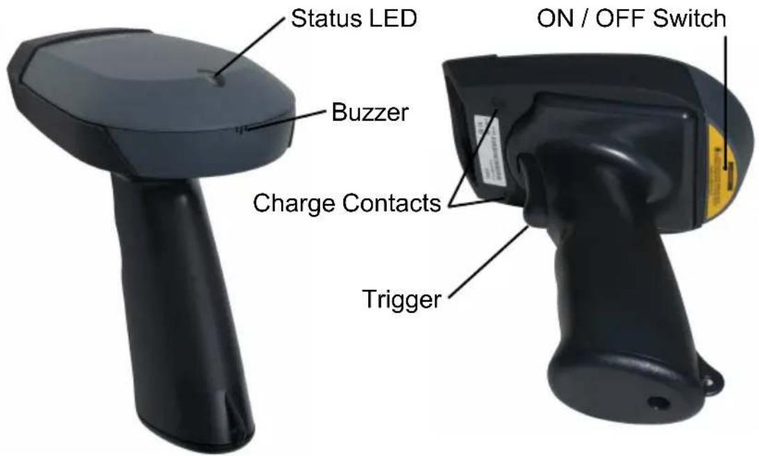
SCANNER PARTS:
Scanner LED
The MS860 has one LED indicator located on the head of the scanner which indicates the operating status of the scanner.
Red LED is ON
When the scanner attempts to read a bar code, the LED will glow red.
Single Green LED Flash
When the scanner successfully reads a bar code the scanner LED flashes green once, and you will hear a single beep.
Flashing Green LED
When the scanner reads a start configuration bar code (order Group 5, instance) and enters configuration mode, the scanner LED will flash green while the scanner simultaneously gives one High-Low-High tone beep. Upon exiting configuration mode, the scanner will give one High tone beep, and the scanner LED will stop flashing.
- The scanner is powered on but not yet connected to the WLAN or the
connection to the WAIN is broken.
- If scans are attempted out of range, communication will be broken, the scanner LED will remain green, and you will hear continuous Hi- Green LED remains ON When the scanner is powered on and connected to the WLAN successfully.
- The first time when you establish the communication, the LED will remain green before VCOM communication is established.
Red LED Flash
The scanner LED flashing red indicates the scanner has low power and you will need to charge the scanner immediately.
INTRODUCTION
Buzzer
The MS860 provides audible feedback while it is in operation. These sounds indicate the operating status of the scanner.
One High Tone Beep
The scanner will beep once after successfully reading a bar code.
One High-Low-High Beep
After scanning a ‘begin configuration’ bar code (“Enter Group 5”, for instance), the scanner LED will flash green while the scanner simultaneously gives one high-low-high tone beep. Upon exiting configuration mode by scanning an “Exit” bar code, the scanner will give one high tone beep, and the scanner LED will stop flashing.
Continuous High-Low Beeps
If scans are attempted out of range, communication will be broken.
The scanner LED will remain red and you will hear a continuous high-low beep from the scanner when you scan bar codes.
If the Access Point is powered off, this means the communication between the scanner and the Access Point is lost. You will also hear a continuous high-low beep from the scanner when you scan bar codes.
INTRODUCTION
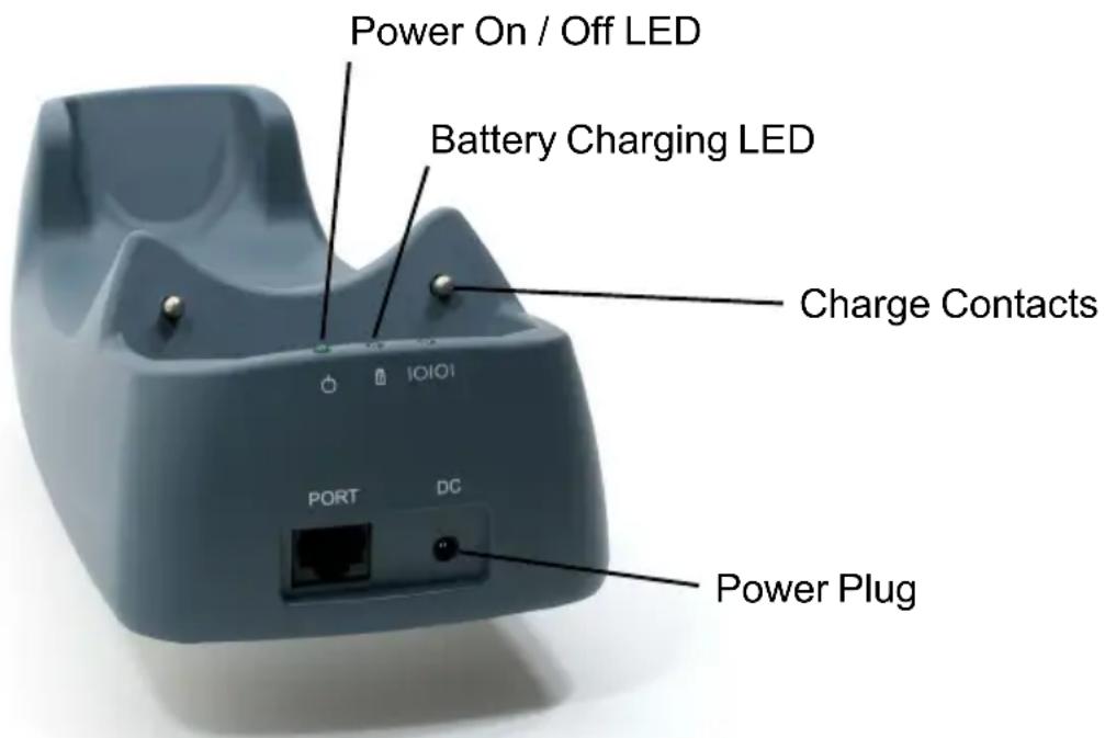
CRADLE PARTS:
Cradle LEDs
The MS860 charging cradle has two LED indicators (power on/off status and battery charging status).
Power ON/OFF Status LED stays ON
When the power adapter plug is connected into the power jack on the cradle, and the power adapter is connected into an AC outlet, the cradle will beep, and the LED on the top of the cradle will remain on.
Battery Charging Status LED remains Red
The red LED indicates the scanner battery is charging.
Battery Charging Status LED remains Green
The LED changes to green when scanner battery charging is complete.
Please Note:
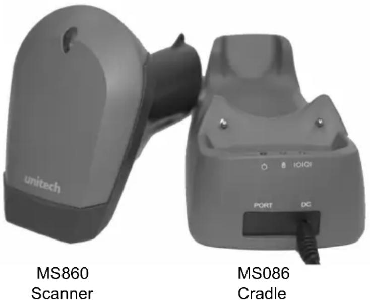
The MS086 Cradle has an interface port (to the left of the power plug) and a communication LED next to the two other LEDs. These components are inactive due to the wireless nature of the MS860 WiFi.
Prior to performing any operation with the scanner, make sure it has been fully charged.
How to determine if the scanner needs recharging:
- During operation, a flashing red scanner LED indicates the scanner has low power.
- When the trigger is pressed and a scan laser line is not visible (do NOT look directly into the scanner), the scanner has no power. Make sure the scanner is not merely switched off.
To charge the scanner, place the unit into the cradle. The battery status LED on the cradle will glow red, indicating the charging process has begun.
To Charge the MS860:
Simply place the MS860 into the MS086 Charging Cradle. Make sure the MS086 Cradle is plugged into an available electrical outlet via its Power Supply.
A complete charging process takes about 4 to 5 hours, during which the cradle's battery charging LED will glow red. After charging is complete the battery charging LED will remain a steady green. When charging the scanner for the first time, make sure the scanner remains on the cradle until after the battery charging LED changes from red to green.
Manufacturer's Suggestion:
If the scanner is not to be used for a long period of time, it is recommended that you turn off the battery power of the scanner. Use an unfolded paper clip to push down the internal power on/off switch, located inside the round hole on the yellow laser warning label of the scanner (see page 5). You will feel a ‘click’ when the internal switch is moved up to the “OFF” position or when the internal switch is moved down to the “ON” position.
To ensure that the scanner has been switched off, press the scanner's trigger and make sure that the scanner's LED does not glow red.
NETWORK SETTINGS
INTRODUCTION
The MS860 WiFi is designed to connect to your computer(s) via the existing wireless network through one of its Access Points (APs), thereby eliminating the dedicated wireless receiving unit required by other types of wireless scanners.
Integrating the MS860 into the wireless network is the same as integrating any other piece of wireless hardware, requiring that you give it its own unique IP address, which can be obtained from your network administrator. The MS860 WiFi's default settings and explanations are shown below and described on the following pages.
| Item | Default Setting |
| IP Address | 192.168.1.250 |
| IP Subnet Mask | 255.255.255.0 |
| Gateway IP Address | 192.168.1.254 |
| SSID | wlandemo |
| RF Channel | 6 |
| WEP | Disabled |
| Authentication Type | Auto |
Note: The default settings must be changed to allow the MS860 and the AP start communicating, and default settings are provided merely as a starting point.
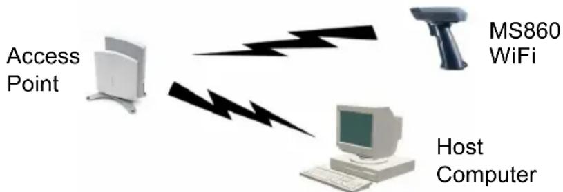
How the MS860 WiFi actually works:
flowchart
graph TD
    A["Access Point"] --> B["Host Computer"]
    B --> C["MS860 WiFi"]
    C -->| lightning bolt| B
Scanners normally communicate directly with host computers via keyboard or RS232 interface. The MS860 WiFi instead communicates over your wireless network with the nearest Access Point (AP), which then communicates with the host computer. The host computer uses the VCOM utility to convert the WiFi signal to a Virtual Com Port (RS232) signal, which the host computer recognizes as one of the standard scanner interfaces.
NETWORK SETTINGS
So, two things must be configured: the MS860's Wireless Network settings, and the host computer's Virtual Com Port settings.
Consult your network administrator for the appropriate network wireless settings for your MS860 which must be manually configured via Scanner Configuration Manager or bar codes (see below and pages 31 to 60).
VCOM should automatically create a “virtual com port” for the Access Point to communicate data through. If this doesn’t happen automatically, then refer to the Troubleshooting section (page 89).
VCOM
The VCOM utility's function is to convert incoming wireless data into Virtual Com Port data that your computer expects from a scanning device.
Unlike SCM or Bar Code Scanning (below) VCOM cannot modify the MS860's configuration. VCOM simply pairs the MS860's existing IP address, configured via SCM or bar code scanning (see below) with it's host computer(s) virtual com port.
Detailed instructions for VCOM start on page 21.
Modifying the WiFi settings:
If the MS860's settings need to be manually modified, this can be accomplished via the two different methods below, each described in full starting on page 10.
SCM
Scanner Configuration Manager (SCM) is a proven and powerful utility for scanner configuration. Easy to use, it is probably the most straightforward method of modifying your MS860's wireless settings. Because of the wireless communication between the MS860 and the host computer, SCM settings cannot be directly downloaded to the MS860. Instead, SCM provides for printing a series of bar codes derived from SCM's configuration, and these bar codes are then scanned by the MS860.
Detailed instructions for SCM start on page 13.
Bar Codes
Direct bar code scanning is the simplest, most direct, but most tedious method of configuring the MS860 scanner. Once mastered, however, it allows the user full “hands-on” control over the MS860’s wireless settings.
Detailed instructions for bar code scanning start on page 17.
NETWORK SETTINGS
GLOSSARY
IP Address
IP Address (short for Internet Protocol) is simply four numbers (like 192.168.1.250) separated by periods that is used to identify a particular device within a network, just as an employee number is used to identify an individual person within a company.
The IP Address can either be automatically assigned by the wireless network or manually assigned by the user. The automatically assigned IP Address is available via your AP software, or you can assign your own IP Address (pages 13 to 17) and see if it's accepted by the network.
IP Subnet Mask
IP Subnet Mask is like the IP Address for the entire network. Every device within a network shares the same IP Subnet Mask. The IP Subnet Mask number is available via your AP software.
Gateway IP Address
The Gateway IP Address is only necessary if your network has outside access, as in a WAN (Wide Area Network). Because of the security issues involved in outside access, the Gateway IP Address is only available from your Network Administrator or Service Provider.
SSID
SSID (Service Set ID) is the name of the wireless Access Point you choose for your MS860 to communicate with. Available via your AP software.
RF Channel
There are 11 potential RF (Radio Frequency) Channels, numbered 1 through 11, to communicate over, and your MS860 and the nearest Access Point will use one of them. Because the MS860 and the AP will sort this out for themselves, it is not necessary for the user to specify a channel, however, a default RF Channel is provided by the MS860 as a starting point.
NETWORK SETTINGS
WEP
WEP (Wireless Encryption Protocol) is a security key for communicating with an access point. If the correct key is not presented, communication is denied. Because WEP is used for security reasons, it must be obtained from your Network Administrator.
Authentication Type
If WEP (see above) is used, then the security key can be presented to the AP in three different ways:
- Disabled - means communication with the AP is not possible if WEP is on because the security key will not be presented.
- Auto - means the MS860 will automatically present the security key when requested by the Access Point.
- On - means that the security key is always presented by the MS860, whether it is requested or not.
You might want to note the following information for future reference. This information is not strictly necessary, but might be useful in order to maintain order over several MS860 units.
Alias
Alias is merely a name for the scanner that would be more easily recognizable than an IP Address. For instance: “Fred’s MS860”, “S103”, or “Warehouse-23”.
Contact
Contact is the name of the IT person or Network Administrator that you would go to in case of trouble.
Location
Location is the usual location of the scanner, be it the “Warehouse”, “Virginia’s Office”, or wherever.
SNMP Community
SNMP (Simple Network Management Protocol) is a software tool to manage wireless networks. If your Network Administrator is using SNMP, then they will be able to give you your SNMP Community name.
NETWORK SETTINGS
NETWORK SETTINGS
There are two methods to configure your scanner to its IP settings (obtained from your Network Administrator) - via Scanner Configuration Manager (SCM) and via manual bar code scanning. SCM has the advantage in that it's quick and easy, and works for most situations. Direct bar code scanning (starting on page 17) offers full "hands on" control over your MS860's IP settings, but can be tedious.
USING SCM FOR SCANNER NETWORK SETTING
Step 1: Install Scanner Configuration Manager (SCM) from the User Guide CD and double click the SCM icon on the desktop.
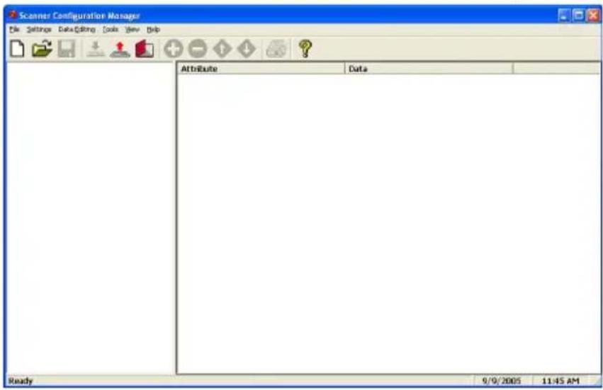
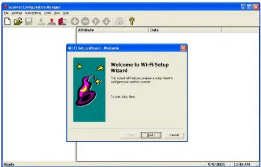
Step 2: Click "Tools" / "Wi-Fi Setup", and the "Welcome to WiFi Setup Wizard" screen appears.
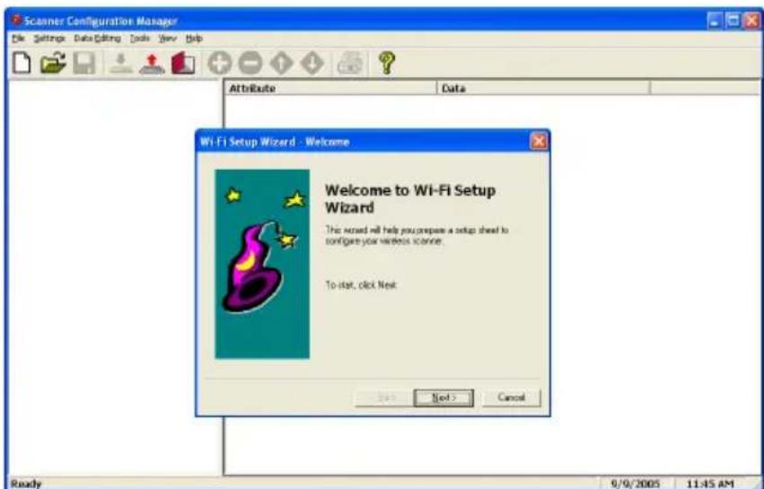
NETWORK SETTINGS
Step 3: Fill in the SSID name of the Access Point (AP). Click "Next".
![Wi-Fi Setup Wizard - SSD Please enter the network name (BSD) of your wireless network, then to 32 character: [Unread] < Back Next > Cancel](/content/2026/05/951877/images/d854f8429c1fb7b5cd89785f7a95dea6a5e1ade93badae20267a9f645d9afdde.jpg)
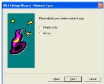
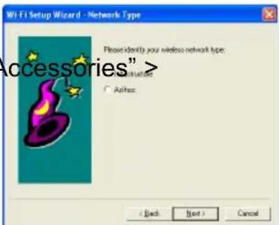
Step 4: Select wireless network type.
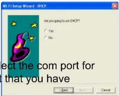
Step 5: Select "Yes" for DHCP on, "No" for DHCP off.
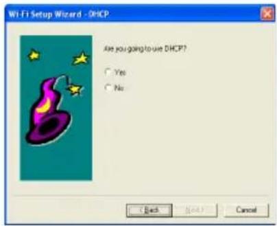
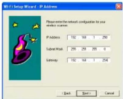
Step 6: If DHCP "Off" is selected, fill in the IP Address, Subnet Mask, and Gateway. Click "Next".
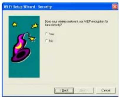
Step 7: Select whether your wireless network is using WEP encryption for data security. Click "Next".
NETWORK SETTINGS
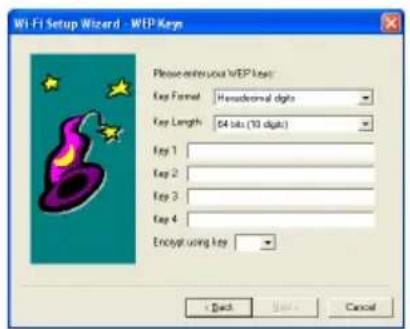
Step 8: If "Yes" was selected in Step 7, fill in the WEP parameters and type a password in the Key 1 field. Click "Next".
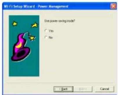
Step 9: Select "Yes" or "No" for Power Saving Mode.
Step 10: Verify the information is correct. Click "Back" to modify the configuration if necessary. Click "Next" when finished.
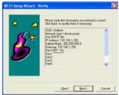
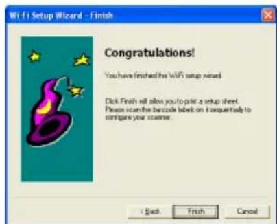
Step 11: Setup is complete.
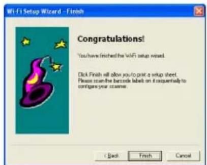
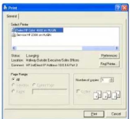
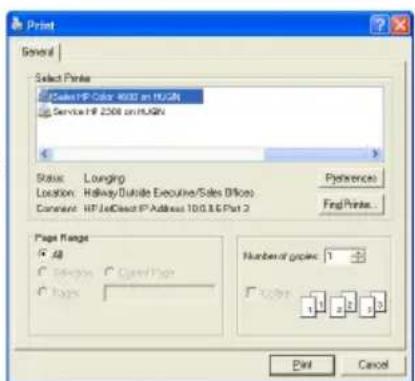
Step 12: Select an appropriate printer to produce a setup sheet containing bar codes. Use your MS860 scanner to scan the barcodes on the sheet sequentially to configure the scanner.
NETWORK SETTINGS
IMPORTANT:
Once you have completed the network configuration for the scanner, VCOM will be required to configure the virtual com port, which means the VCOM utility must run in the background. This is detailed on pages 21 to 24.
Some Access Points may not be able to re-connect to the MS860 after it's been out of range. In this case the scanner will need to be powered off and powered on again, and the VCOM communication must be re-started.
VCOM Utility supports Windows2000 and XP.
Unfortunately, Windows98 and NT are not currently supported.
NETWORK SETTINGS
USING BAR CODES TO SET SCANNER NETWORK:
The WLAN default settings are shown below.
WLAN Default Settings:
| Item | Default Setting |
| IP Address | 192.168.1.250 |
| IP Subnet Mask | 255.255.255.0 |
| Gateway IP Address | 192.168.1.254 |
| SSID | Wlandemo |
| RF Channel | 6 |
| WEP | Disabled |
| Authentication Type | Auto |
Use the TCP/IP barcode chart on page 81 and the ASCII Chart on pages 83 to 86 to configure your scanner to your own network settings, as the example below:
SSID: MySSID
IP: 192.168.1.100
Mask: 255.255.255.0
Please follow the steps below:
Scan the Enter Group 10 bar code
Then scan: SSID Space M y S S I D CR
Then scan: IP Space 1 9 2 . 1 6 8 . 1 . 1 0 0 CR
Then scan: MASK Space 2 5 5 . 2 5 5 . 2 5 5 . 0 CR
Lastly, scan: SE CR EE
Other than that last line, it's pretty self-explanatory. Several parameters can be modified together in one session, as above. Or, only one parameter can be modified per session, as below. The last commands - SE, CR, EE - are simply a sequence to end the programming mode, and along with Enter Group 10 must be included whenever programming network settings via bar code.
To turn DHCP on, scan the following sequence:
Scan the Enter Group 10 bar code
Then scan: DHCP Space 1 CR
Lastly, scan: SE CR EE
NETWORK SETTINGS
General Command List:
MODE <B(SS) / A(d-hoc) / P(seudo / BSS)>, Set network mode
SSID <SSID>, Set SSID

CHAN <1 - 14>, Set channel

PSMODE <1 / 0>, PS mode ON/OFF

WEP <1 / 0>, WEP ON/OFF

DEFAULT Restore configuration to factory default

SAVE Save configuration to flash

EXIT Save configuration to flash

SE Save and exit configuration

BAUD <0 / 1 / 2 / 3>, Set RS232 Baudrate

AA <O(pen) / S(hare) / A(uto)>, Set Authentication Algorithm

WK <1 - 4> <Key in Hex>

WKID <1 - 4>, Set WEP Key ID

IP <IP address>, Set IP

MASK <IP address>, Set IP Mask

GW <IP address>, Set Gateway IP

DHCP <1 / 0>, Set DHCP client ON or OFF
- IP
Set IP address
Example: IP Space 192.168.1.250 CR
- GW
Set gateway IP address
Example: IP Space 192.168.1.1 CR
- MASK
Set network MASK IP address
Example: MASK Space 255.255.255.0 CR
- DHCP
Turn DHCP client on or off
Example: DHCP Space 1 CR (turn on DHCP client)
Example: DHCP Space 0 CR (turn off DHCP client)
- SSID
Set SSID
Example: SSID Space wlandemo CR (set SSID to "wlandemo")
- MODE
Set mode to infrastructure or ad-hoc
Example: MODE Space B CR (set mode to infrastructure)
Example: MODE Space A CR (set mode to ad-hoc)
MS860 WiFi Manual
NETWORK SETTINGS
7. WEP
Turn WEP on or off
Example: WEP Space 1 CR (turn on WEP)
Example: WEP Space 0 CR (turn off WEP)
8. WKID
Set which WEP key that you want to use, of which you have four.
Example: WKID Space 1 CR (use WEP key number 1)
Example: WKID Space 2 CR (use WEP key number 2)
Example: WKID, Space 3 CR (use WEP key number 3)
Example: WKID Space 4 CR (use WEP key number 4)
9. WK
Set WEP key association with a WEP key number.
Following examples set 64 bit encryption keys:
Example: WK Space 1 2002031105 CR (WEP key number 1 - 2002031105)
Example: WK Space 2 2002031106 CR (WEP key number 2 - 2002031106)
Example: WK Space 3 2002031107 CR (WEP key number 3 2002031107)
Example: WK Space 4 2002031108 CR (WEP key number 4 2002031108)
10. AA
Set Authentication Algorithm to OPEN, SHARE, or AUTO
Example: AA Space O CR (set authentication algorithm to OPEN)
Example: AA Space S CR (set authentication algorithm to SHARE)
Example: AA Space A CR (set authentication algorithm to AUTO)
11. PSMODE
Turn power saving mode on or off
Example: PSMODE Space 1 CR (turn power saving mode on)
Example: PSMODE Space 0 CR (turn power saving mode off)
12. CHAN
Set channel 1\~14 when under ad-hoc mode
Example: CHAN Space 1 CR (set to channel 1)
Example: CHAN Space 2 CR (set to channel 2)
Example: CHAN Space 14 CR (set to channel 14)
NETWORK SETTINGS
13. SAVE
Save the configuration settings
Example: SAVE CR
14. SE
Save the configuration settings and reboot
Example: SE CR
15. DEFAULT
Restore configuration settings to factory default, and automatically reboot the module
Example: DEFAULT CR
16. EXIT
Reboot the module without saving any configuration changes
Example: EXIT CR
IMPORTANT:
Once you have completed the network configuration for the scanner, VCOM will be required to configure the virtual com port, which means the VCOM utility must run in the background. This is detailed on pages 21 to 24.
Some Access Points may not be able to re-connect the MS860 and its cradle after it's been out of range. In this case the scanner will need to be powered off and powered on again, and the VCOM communication must be re-started.
VCOM Utility supports Windows2000 and XP.
Unfortunately, Windows98 and NT are not currently supported.
Before entering into Command Mode, power off the scanner and then scan “Enter Group 10” on page 81 within 5 seconds after powering the scanner back on.
NETWORK SETTINGS
After you have configured your MS860's IP settings, follow the steps below and on the next page to install and start VCOM. VCOM establishes a "virtual com port" on your host computer that coordinates with your MS860's IP address.
INSTALLING VIRTUAL COM
Step 1: Install VCOM utility from the User Guide CD, or use your CD browser and double-click Setup.exe to install VCOM.
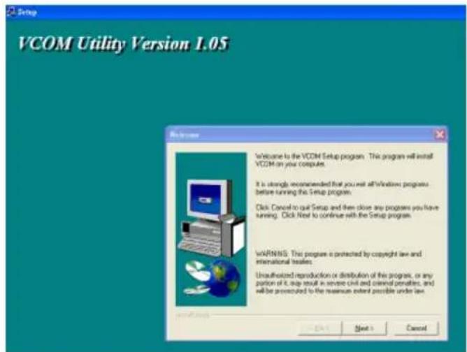
Step 2: Click "Next", and then select the directory into which you would like VCOM installed. Default is C:\Program Files\VCOM
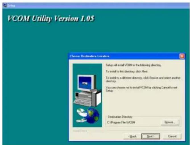
Step 3: Click "Next" and select the program folder you want added to the Start menu.
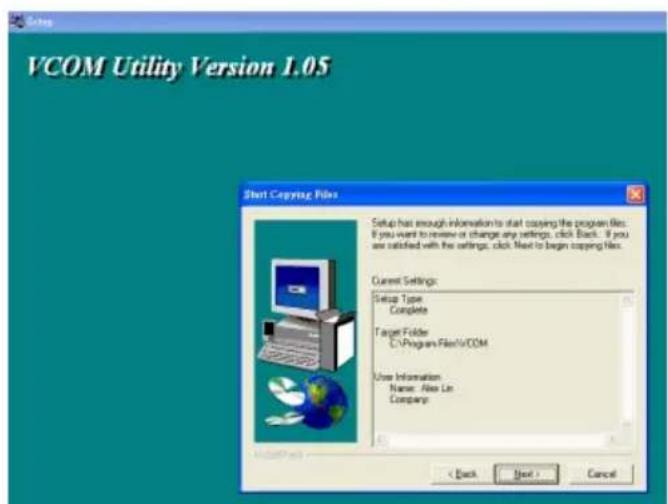
NETWORK SETTINGS
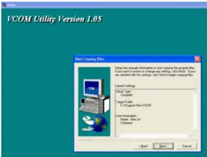
Step 4: Click "Next" and confirm information. The installation procedure will start automatically.
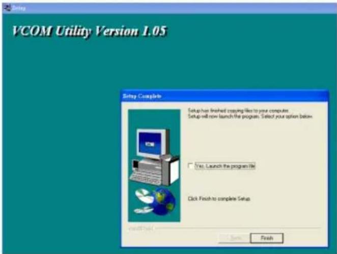
Step 5: Click "Finish" to complete the installation process.
NETWORK SETTINGS
START VIRTUAL COM:
Step 1: Start the Virtual Com utility from the Icon Tray.
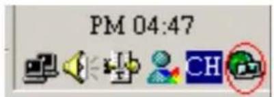
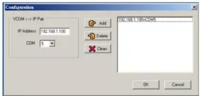
Click the "Config" button.
![Virtual COM Utility Version 1.02 File Config Stop Clear Search Exit Messages [10/7/2005 2:20.05 PM] VCOM started by user [10/7/2005 2:20.05 PM] VCOM [COM5] created [10/7/2005 2:20.05 PM] Connecting to 10.0.0.68 [10/7/2005 2:20.06 PM] Connection state changed: 10.0.0.68 CONNECTED](/content/2026/05/951877/images/6345d420e2ea7d04441e8007a484c9fa7fca41db0e2a4dadc3721d4a790862c3.jpg)
Step 2: Set the virtual com port associated with the corresponding IP address to your wireless module. Click the "Add" button to add a VCOM = IP pair to the list on the right. Click the "OK" button.
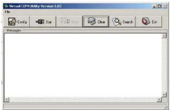
Step 3: Click the Start ("Star") button to start the virtual com communication with your wireless module.
NETWORK SETTINGS
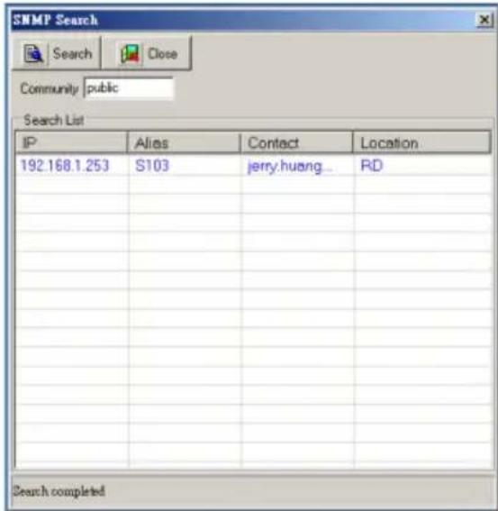
Step 4: Click the "Search" button. The found wireless device will be added to the IP List panel.
IMPORTANT:
Once you have completed the network configuration for the scanner (pages 13 to 17), VCOM will be required to configure the virtual com port, which means the VCOM utility must run in the background.
Some Access Points may not be able to re-connect to the MS860 after it's been out of range. In this case the scanner will need to be powered off and power on again, and the VCOM communication must be re-started.
VCOM Utility supports Windows2000 and XP. Unfortunately, Windows98 and NT are not currently supported.
NETWORK SETTINGS
Using Monitor.exe for scanner network settings, and the host computer's Virtual Com Port settings.
(Monitor.exe is available from Unitech) Consult your network administrator for the appropriate network wireless settings for your MS860 which must be manually config-
- Before using the monitor.exe for configuration, please install vcom utility in your PC first.
VCOM should automatically create a "virtual com port" for the
-
Double click DevMgrU.
-
Once the scanner is connected to the access point, the scanner should be searched and found by the monitor.exe. (Or you can click "ReSearch"Buttonity's search device) incoming wireless data into Virtual Com Port data that your computer expects from a scanning device.
Unlike SCM or Bar Code Scanning (below) VCOM cannot modify the MS860's configuration. VCOM simply pairs the MS860's existing IP address, configured via SCM or bar code scanning (see below) with it's host computer(s) virtual com port.
Detailed instructions for VCOM start on page 20.
Modifying the WiFi settings:
- If the configure the network setting of the scanner and select the scanner in the list that you want to configure a link "Configuration" which selected in "Network" on page 12.
SCM
Scanner Configuration Manager (SCM) is a proven and powerful utility for scanner configuration. Easy to use, it is probably the most straightforward method of modifying your MS860's wireless settings. Because of the wireless communication between the MS860 and the host computer, SCM settings cannot be directly downloaded to the MS860. Instead, SCM provides for printing a series of bar codes derived from SCM's configuration, and these bar codes are
- Network setting should be shown. You can change the IP address, subDETAILASK and other network settings after setting, click "OK".
Bar Codes
Direct bar code scanning is the simplest, most direct, but most tedious method of configuring the MS860 scanner. Once mastered, however, it allows the user full "hands-on" control over the MS860's wireless settings.
Detailed instructions for bar code scanning start on page 16.
NETWORK SETTINGS
GLOSSARY
IP Address
IP Address (short for Internet Protocol) is simply four numbers (like 192.168.1.250) separated by periods that is used to identify a particular device within a network, just as an employee number is used to identify an individual person within a company.
The IP Address can either be automatically assigned by the wireless network or manually assigned by the user. The automatically assigned IP Address is available via your AP software, or you can assign your own IP Address (pages 12 to 19) and see if it's accepted by the network.
IP Subnet Mask page prompt the user to enter the username and password click "Authorize" IP Address for the entire network. Note: the default Wuser name is "admin" the password is "Subnet Mask." password Subnet Mask number is available via your AP software.
Gateway IP Address
The Gateway IP Address is only necessary if your network has outside access, as in a WAN (Wide Area Network). Because of the security issues involved in outside access, the Gateway IP Address is only available from your Network Administrator or Service Provider.
SSID
SSID (Service Set ID) is the name of the wireless Access Point you choose for your MS860 to communicate with. Available via your AP software.
- After reboot, the settings should be changed to new settings. RF Channel
There are 11 potential RF (Radio Frequency) Channels, numbered 1 through 11, to communicate over, and your MS860 and the nearest Access Point will use one of them. Because the MS860 and the AP will sort this out for themselves, it is not necessary for the user to specify a channel, however, a default RF Channel is provided by the MS860 as a starting point.
NETWORK SETTINGS
Configure the virtual com port using monitor.exe:
WEP (Wireless Encryption Protocol) is a security key for com- 1. On monitor.exe, click Configuration. Select Virtual COM: presented, communication is denied. Because WEP is used for security reasons, it must be obtained from your Network Admin- istrator.
Authentication Type
If WEP (see above) is used, then the security key can be presented to the AP in three different ways:
- Disabled - means communication with the AP is not possible if WEP is on because the security key will not be presented. 2. On "Select Port", select the com port you want to use. Then, click "Set" button. - Auto - means the MS860 will automatically present the security key when requested by the Access Point.
- On - means that the security key is always presented by the MS860, whether it is requested or not.
You might want to note the following information for future reference. This information is not strictly necessary, but might be useful in order to maintain order over several MS860 units.
Alias
Alias is merely a name for the scanner that would be more easily recognizable than an IP Address. For instance: "Fred's 3. "Advanced" is enabled. You can click "Advanced" button to configure the virtual com port further.
Contact
Contact is the name of the IT person or Network Administrator that you would go to in case of trouble.
Location
Location is the usual location of the scanner, be it the "Warehouse", "Virginia's Office", or wherever.
SNMP Community
SNMP (Simple Network Management Protocol) is a software tool to manage wireless networks. If your Network Administrator is using SNMP, then they will be able to give you your SNMP Community name.
NETWORK SETTINGS
4. Keep the default settings of the server port and server IP. NETWORK SETTINGS
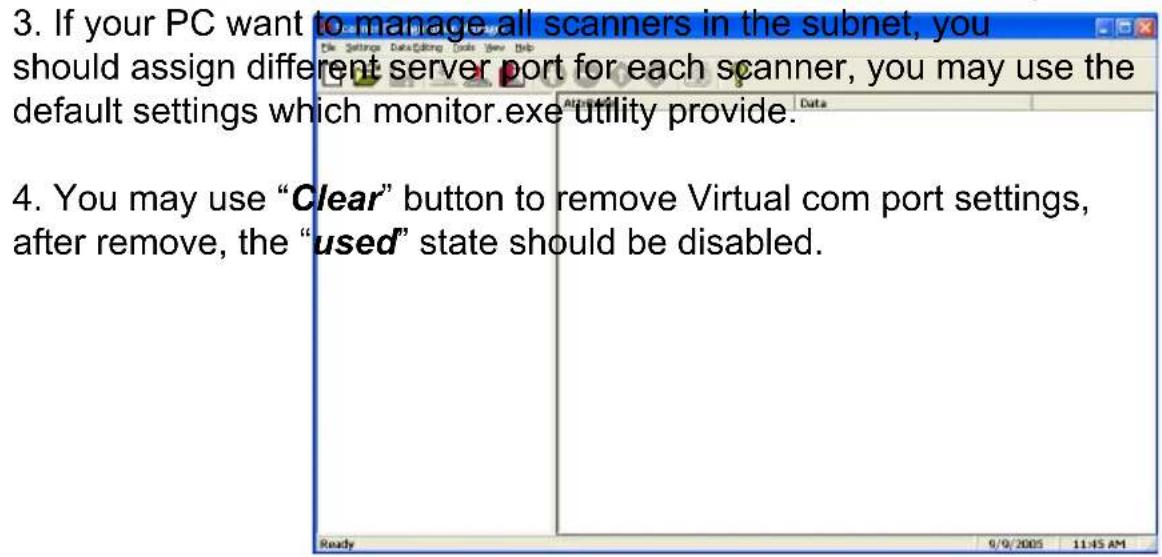
There are two methods to configure your scanner to its IP settings (obtained from your Network Administrator) - via Scanner Configuration Manager (SQM) and via manual barcodes scanning. SCM has the 1. The PC which run monitor.exe utility should detect the IP address advantage in that it's quick and easy and works for most situations itself and the IP address should be act as PC server. If Server IP is different from the one which the monitor.exe detected, you may assign control over your MS860's IP settings, but can be tedious.
2. You should not change the Server port & Server if if you want to use the PC which run moniter.exe utility to act as the TCP server.
Step 1: Install Scanner Configuration Manager (SCM) from the User Guide CD and double click the SCM icon on the desktop.
Step 2: Click "Tools" / "Wi-Fi Setup", and the "Welcome to WiFi Setup Wizard" screen appears.
NETWORK SETTINGS
Scan data and send data via WiFi:
Point (AP). Click "Next".
- After you have set the network configuration set the virtual com port, you are ready to scan to your server thru the WiFi.
- When your scanner connected to the WLAN, the flashing green LED on the scanner turn into steady green. Step 4. Select wireless network type.
- On your PC, select "Start" > "Program" > "Accessories" > "Communication" > "Remote Terminal".
![Wi-Fi Setup Wizard - SSD Please enter the network none (SSD) of your worker network, led to 32 characters: [Unread] for your scanner and data and transmit them < Back Next > Cancel](/content/2026/05/951877/images/26ce6ef764f5b7fee7a33acfcf665058ce50822cbeff4c257b8122c80e3b604c.jpg)
Step 5: Select "Yes" for DHCP on, "No" for DHCP off.
- Enter a name for the connection. Then, select the com port for the connection (You must select the com port that you have configured in VCOM, pg 23), click "OK".
Step 6: If DHCP "Off" is selected, fill in the IP Address, Subnet Mask, and Gateway. Click "Next".
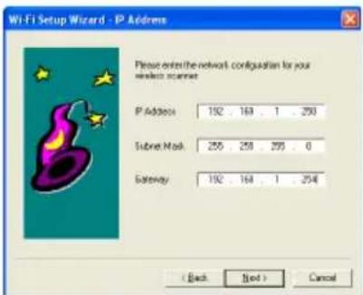
Step 7: Select whether your wireless network is using WEP encryption for data security. Click "Next".
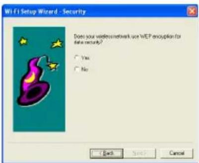
NETWORK SETTINGS
- Define the RS232 settings according to page 88. RS232 Default
Step 6. If Yes was selected in Step 7, if Settings, click "OK" the WEP parameters and type a password in the Key 1 field. Click "Next".
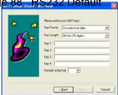
Step 9: Select "Yes" or "No" for Power Saving Mode.
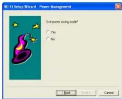
- Press the scan button to scan the barcode Step 10: Verify the information is correct.
Click "Back" to modify the configuration if necessary.
Click "Next" when finished.
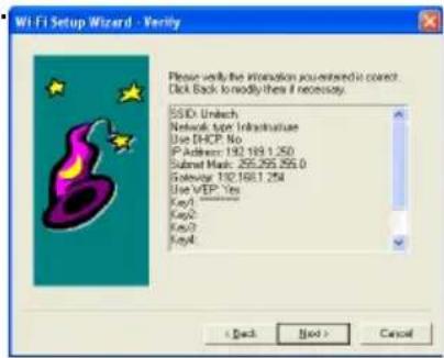
Step 11: Setup is complete.
Step 12: Select an appropriate printer to produce a setup sheet containing bar codes. Use your MS860 scanner to scan the barcodes on the sheet sequentially to configure the scanner.
SCANNER CONFIGURATION MANAGER
Scanner Configuration Manager software is the simplest and most foolproof way to configure your scanner settings.
Start It Up
After loading and starting SCMSetup.exe, the icon to the right will appear on your desktop:

Click on the SCM icon and the screen to the right appears:
As you can see, you are presented with a blank work area and a row of icons across the top. Following is an explanation of each of the icons:
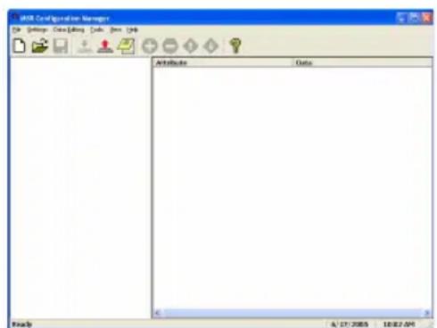


Above, from left to right, are the standard Windows icons for "New Document", "Open File", and "Save File".
Reader Configuration Manager saves configuration settings in .cfg files, so you can have access to a variety of different reader configurations that you've set up.
To reset the reader back to factory default, click on the “New Document” icon, click the “Print” icon (see next page), and scan the resulting bar codes with your MS860.


The above icon furthest to the right opens a Test Pad (Notepad) where you can view the actual reader output. The other two icons are non-functional in the MS860 WiFi because of its wireless nature, but they represent download settings to scanner and upload settings to computer for other scanner models.
Downloading to the MS860 can otherwise be accomplished by clicking the Print icon (see next page) and scanning the resulting configuration bar codes.
SCANNER CONFIGURATION MANAGER

The above four icons are used in the “Data Editing” feature of SCM.
From left to right they are the “Add a Formula” icon, the “Remove a Formula” icon, and the right-hand two are the “Move Formula” icons that move selected formulas up or down in relation to each other.
For information on data editing, see page 78.

Click this icon to print a series of bar codes that you can scan in order to configure your scanner to the current SCM settings. If you can produce PDF files via Acrobat, your SCM configuration can be sent via e-mail to remote locations where they can be scanned from a printed PDF file (without having to run SCM).

Help is just a click away.
SCANNER CONFIGURATION MANAGER
Try It!
Click the SCM Icon, if you haven't already done so.

Two work areas appear with a row of icons along the top. Click the icon furthest to the left (new file).
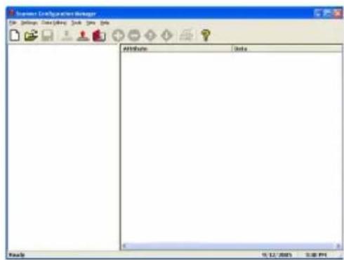
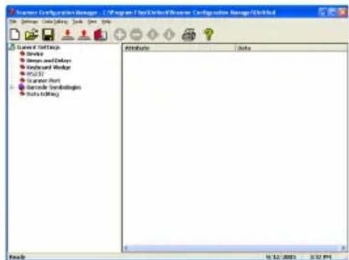
The screen to the right appears. Click on any of the selections under "Current Settings" to view its "Attributes".
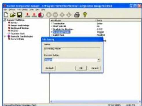
Double-click on any of the “Attributes” to edit that attribute. This is done via a drop-down menu.
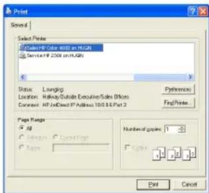
After selecting your configuration settings, click on the Print icon (second icon from the right) to print a series of bar codes that you can scan in sequentially to program your scanner.
SCANNER CONFIGURATION MANAGER
Using SCM for scanner network setting:
Settings Step 1. Install SCM program from user guide CD and double click the scanner configuration manager icon on the desktop, their attributes, and the effects each of these will have on data output from your MS860.
Beeps and Delays
The three attributes for "Beeps and Delays" are: "Beep Tone", "Interblock Delay", and "Intercharacter Delay".
Beep Tone
Select a value from "None" to "High" to set the loudness of the tone, or select "Low to High" or "High to Low" to set the characteristic of the tone.
Default is "Medium".
Step 2: Click ToolsWi-Fi Setup, welcome to WiFi Setup
Wizard screen will appear. Interblock Delay
Interblock delay is the time duration that can be inserted between one block of data and another. This function is analogous to the time duration required between dialing a phone number's country code and the phone number itself. The interblock delay can be inserted via SCM's Data Editing function (see page 45).
Default is "10 ms".
Intercharacter Delay
Intercharacter delay is the time duration between data characters sent from the scanner to the computer. Intercharacter delay is usually inserted when the data flow must be slowed down to accommodate a slower computer.
Default is "1 ms".
Keyboard Wedge
Your Unitech reader contains a built-in data decoder that translates raw bar code input into Keyboard Scan Code, or ASCII Code in the case of RS232 interface readers, with the result that scanned data exits the reader as if you had typed the text.
The four keyboard wedge parameters are listed on the following page.
MS860 WiFi Manual
SCANNER CONFIGURATION MANAGER
Step 3: Fill in the SSID name of access point (AP) and click on "Next" button
Function Code
Function Code determines how function code characters from the MS860 are output.
- If Yes is selected, then scanned function codes will output as if their corresponding function keys were pressed. For instance - scanning an F1 label will display a "Help" pop-up box, F3 will display a "Find" pop-up box, etc.
- If No is selected, the scanned function codes will output special character strings defined by Unitech for non-print character output. Default is "Yes".
Caps-Lock
The Caps-Lock function determines how the Caps Lock key controls the case of alphabetical characters. The three options below are available:
Stepu4o Select wireless network types the Caps Lock key status and informs the decoder accordingly.
- Lower Case manually coordinates the physical state of the Caps Lock key with the Caps Lock state of the decoder. For example, if the Caps Lock LED is not lit, then "Lower Case" should be selected.
- Upper Case is the same as Lower Case (above) except that it applies to the upper case state. If the Caps Lock LED is lit, then "Upper Case" should be selected.
Default is "Auto Trace".
Language
Your MS860 can output characters using eleven different language sets, including:
Danish
U.S. English
U.K. English
French
German
Italian
Norwegian
Swedish
Spanish
Swiss
Alt Key Mode
Default is "U.S."
Use Numeric Keypad
The ASCII Code for numeric input from the keypad part of the keyboard is different from that of the upper row of the keyboard proper. Some accounting programs specifically require keypad input, and for that reason, the MS860's decoder can output read data as either keypad or keyboard (upper row) output.
Default is "No"
SCANNER CONFIGURATION MANAGER
Step 5: Select DHCP on or off. Click "Yes" for DHCP on and click "No" for DHCP off.
The RS232 input characteristics of the MS860 can be modified according to the following nine parameters:
Baud Rate
Baud Rate (bits per second) refers to the speed of the data from the MS860. Normally, the baud rate of the host RS232 port should match that of the input device.
Default is "9600 Baud".
Parity
Parity is an archaic technique used to detect data transmission errors by adding an extra bit to each character. This scheme has been supplanted in modern communication devices by "Error Correction".
Default (and the current universal standard) is "No Parity".
Step 6: If select DHCP "off", fill in IP address, Subnet Mask and Gateway, click on "NEXT" button
Data bit refers to the number of bits per byte that are dedicated to data (minus start/stop bits).
Default (and the current universal standard) is "8 Data Bits".
Handshaking
Handshaking is the mechanism that controls the speed of data flow so that a slower receiver of data is not overwhelmed by a faster sender of data. Selections are:
Ignore
RTS (request to send)
Enabled at Power Up
RTS Enabled in Communication
Default is "Ignore".
ACK/NAK
Data characters that are sent from the receiver to the sender in order to "acknowledge" or "not acknowledge" the receipt of the data without error. Rarely used these days.
Default (and the current universal standard) is "No".
SCANNER CONFIGURATION MANAGER
Step 7: Select "Yes" or "No" if your wireless network using WEP encryption for data security or not, click "Next".
BCC Character
Block Check Character. An error checking character added for data integrity.
Default is "No".
Time Out
The ACK/NAK function (see previous page) can be given a limited time (from 1 to 10 seconds) or an unlimited time to operate.
Default is "1 Second".
Data Direction
Three options are available for data direction: Step 8. If select Yes in step 7, choose key format and key length. Type password in Key 1 field, click "Next".
Send to Host & Terminal
Send to Terminal
Default is "Send to Host".
Receive Terminator
A user-definable Receive Terminator can be inserted at the end of input data. Pre-defined receive terminators include:
•
•
•
•
- Any Letter (data editing)
- <*> Interblock Delay (data editing)
- <"> (quotation marks)
-
- <<< < (less than)
- >>> > (greater than)
The above special characters must be bracketed by < > symbols as shown.
Function codes (F keys, cursor up, Enter, etc.) can also be inserted via hexadecimal code (accessible in a linked menu) and must include surrounding brackets (<>).
Letters and numbers should be entered directly by keyboard input without surrounding brackets (<>).
Default is "None".
SCANNER CONFIGURATION MANAGER
Step 9: Select "YES" for using power saving mode. Click "Next".
Scanner Port
Scanner Port parameters refer to scanner functions (such as Double Verification, Scanning Mode, etc.) and some simple data editing features. For more powerful data editing, refer to the Data Editing section starting on page 44.
Terminator
The Terminator is a command that follows the input of bar code data.
Four different terminators can be selected here:
"Enter"
"Return (on numeric keypad)"
"Field Exit or Right Control"
"None"
Alternative terminators (such as Tab) can be configured via the Step 10. Please verify if the information is correct, click Next.
Postamble function (see page 34).
Default is "Enter".
SCANNER CONFIGURATION MANAGER
Step 11: You will see the screen for finished Wi-Fi Setup wizard
Scanner Port, continued
Use Code ID
The Code ID function can be used to identify the type of bar code that is being scanned by inserting an identifying letter (refer to the chart at right) at the beginning of the bar code input.
For example: if the Code ID function is on, and a bar code string of "54321" was output as "M54321", the bar code would thus be identified as type Code 39. Default is "No".
Step 12: Click "Finish" will allow you to pri please scan the barcode labels on it to co
| Codabar | N |
| Code 11 / Telpen | J |
| Code 32 | T |
| Code 39 | M |
| Code 93 | L |
| Code 128 | K |
| Delta Code | D |
| EAN-8 | FF |
| EAN-13 | F |
| I 2 of 5 | I |
| Label Code IV or V | B |
| MSIint out a setup sheet,Plessey Code, nfigure your scanner. | O |
| P | |
| S 2 of 5 | H |
| Toshiba Code | C |
| UCC / EAN 128 | JC1 |
| UPC-A | A |
| UPC-E | E |
Double Verification
Double Verification enables the MS860 to verify the accuracy of the output by outputting only after a specified number (from 0 to 7) of identical results. For instance, if 3 is selected, the MS860 will not output the bar code data until it's obtained 4 identical scan results (the original scan plus 3 verifying scans).
Because the MS860 normally scans at a rate of 33 scans per second, this process should take less than a fraction of a second, even for higher values, for good quality bar code labels.
Default is "0-Off".
SCANNER CONFIGURATION MANAGER
Settings
Following is a detailed discussion of each of the settings, their attributes, and the effects each of these will have on data output from your MS860.
Beeps and Delays
The three attributes for “Beeps and Delays” are: “Beep Tone”, “Interblock Delay”, and “Intercharacter Delay”.
Beep Tone
Select a value from “None” to “High” to set the loudness of the tone, or select “Low to High” or “High to Low” to set the characteristic of the tone.
Default is "Medium".
Interblock Delay
Interblock delay is the time duration that can be inserted between one block of data and another. This function is analogous to the time duration required between dialing a phone number's country code and the phone number itself. The interblock delay can be inserted via SCM's Data Editing function (see page 57).
Default is "10 ms".
Intercharacter Delay
Intercharacter delay is the time duration between data characters sent from the scanner to the computer. Intercharacter delay is usually inserted when the data flow must be slowed down to accommodate a slower computer.
Default is "1 ms".
Keyboard Wedge
Your Unitech reader contains a built-in data decoder that translates raw bar code input into Keyboard Scan Code, or ASCII Code in the case of RS232 interface readers, with the result that scanned data exits the reader as if you had typed the text.
The four keyboard wedge parameters are listed on the following page.
MS860 WiFi Manual
Keyboard Wedge, continued
Function Code
Function Code determines how function code characters from the MS860 are output.
- If Yes is selected, then scanned function codes will output as if their corresponding function keys were pressed. For instance - scanning an F1 label will display a "Help" pop-up box, F3 will display a "Find" pop-up box, etc.
- If No is selected, the scanned function codes will output special character strings defined by Unitech for non-print character output. Default is "Yes".
Caps-Lock
The Caps-Lock function determines how the Caps Lock key controls the case of alphabetical characters. The three options below are available:
- Auto Trace automatically determines the Caps Lock key status and informs the decoder accordingly.
- Lower Case manually coordinates the physical state of the Caps Lock key with the Caps Lock state of the decoder. For example, if the Caps Lock LED is not lit, then “Lower Case” should be selected.
- Upper Case is the same as Lower Case (above) except that it applies to the upper case state. If the Caps Lock LED is lit, then "Upper Case" should be selected.
Default is "Auto Trace".
Language
Your MS860 can output characters using eleven different language sets, including:
| Danish | French | Norwegian | Swiss |
| U.S. English | German | Swedish | |
| U.K. English | Italian | Spanish | Alt Key Mode |
Default is "U.S."
Use Numeric Keypad
The ASCII Code for numeric input from the keypad part of the keyboard is different from that of the upper row of the keyboard proper. Some accounting programs specifically require keypad input, and for that reason, the MS860's decoder can output read data as either keypad or keyboard (upper row) output.
Default is "No"
SCANNER CONFIGURATION MANAGER
RS232
The RS232 input characteristics of the MS860 can be modified according to the following nine parameters:
Baud Rate
Baud Rate (bits per second) refers to the speed of the data from the MS860. Normally, the baud rate of the host RS232 port should match that of the input device.
Default is "9600 Baud".
Parity
Parity is an archaic technique used to detect data transmission errors by adding an extra bit to each character. This scheme has been supplanted in modern communication devices by "Error Correction".
Default (and the current universal standard) is "No Parity".
Data Bit
Data bit refers to the number of bits per byte that are dedicated to data (minus start/stop bits).
Default (and the current universal standard) is "8 Data Bits".
Handshaking
Handshaking is the mechanism that controls the speed of data flow so that a slower receiver of data is not overwhelmed by a faster sender of data. Selections are:
Ignore
RTS (request to send)
Enabled at Power Up
RTS Enabled in Communication
Default is "Ignore".
ACK/NAK
Data characters that are sent from the receiver to the sender in order to “acknowledge” or “not acknowledge” the receipt of the data without error. Rarely used these days.
Default (and the current universal standard) is "No".
RS232, continued
BCC Character
Block Check Character. An error checking character added for data integrity.
Default is "No".
Time Out
The ACK/NAK function (see previous page) can be given a limited time (from 1 to 10 seconds) or an unlimited time to operate.
Default is "1 Second".
Data Direction
Three options are available for data direction:
Send to Host
Send to Host & Terminal
Send to Terminal
Default is "Send to Host".
Receive Terminator
A user-definable Receive Terminator can be inserted at the end of input data. Pre-defined receive terminators include:
Tab Carriage Return
•Line Feed Any Digit (data editing) - Any Letter (data editing)
- <*> Interblock Delay (data editing)
- <"> (quotation marks)
- Character in hexadeximal notation
- <<< < (less than)
-
(greater than)
The above special characters must be bracketed by < > symbols as shown.
Function codes (F keys, cursor up, Enter, etc.) can also be inserted via hexadecimal code (accessible in a linked menu) and must include surrounding brackets (<>).
Letters and numbers should be entered directly by keyboard input without surrounding brackets (<>).
Default is "None".
SCANNER CONFIGURATION MANAGER
Scanner Port
Scanner Port parameters refer to scanner functions (such as Double Verification, Scanning Mode, etc.) and some simple data editing features. For more powerful data editing, refer to the Data Editing section starting on page 57.
Terminator
The Terminator is a command that follows the input of bar code data.
Four different terminators can be selected here:
"Enter"
"Return (on numeric keypad)"
"Field Exit or Right Control"
"None"
Alternative terminators (such as Tab) can be configured via the Postamble function (see page 47).
Default is "Enter".
Scanner Port, continued
Use Code ID
The Code ID function can be used to identify the type of bar code that is being scanned by inserting an identifying letter (refer to the chart at right) at the beginning of the bar code input.
For example: if the Code ID function is on, and a bar code string of "54321" was output as "M54321", the bar code would thus be identified as type Code 39. Default is "No".
| Codabar | N |
| Code 11 / Telpen | J |
| Code 32 | T |
| Code 39 | M |
| Code 93 | L |
| Code 128 | K |
| Delta Code | D |
| EAN-8 | FF |
| EAN-13 | F |
| I 2 of 5 | I |
| Label Code IV or V | B |
| MSI | O |
| Plessey Code | P |
| S 2 of 5 | H |
| Toshiba Code | C |
| UCC / EAN 128 | JC1 |
| UPC-A | A |
| UPC-E | E |
Double Verification
Double Verification enables the MS860 to verify the accuracy of the output by outputting only after a specified number (from 0 to 7) of identical results. For instance, if 3 is selected, the MS860 will not output the bar code data until it's obtained 4 identical scan results (the original scan plus 3 verifying scans).
Because the MS860 normally scans at a rate of 33 scans per second, this process should take less than a fraction of a second, even for higher values, for good quality bar code labels.
Default is "0-Off".
Scanner Port, continued
Scanning Mode
Scanning mode refers to the method by which scans are initiated, whether by pressing a trigger, or simply presenting a bar code to a continuously reading scanner. Scanning can occur in seven different ways:
- Trigger scan causes the scanner light to remain on as long as the trigger is depressed, whether the bar code is recognized or not.
- Flashing causes the scanner to flash continuously after the trigger is briefly pressed until it detects a bar code and outputs the data. The scanner light will then remain on in anticipation of another bar code for approximately 12 seconds, after which it will begin flashing again. A second trigger press stops the scanning.
- Multiscan allows multiple scans while holding down the trigger.
- One Press One Scan causes the scannerlight to remain on after the trigger is briefly depressed until a bar code is recognized and
- Test is similar to the Flash setting except that the scanner outputs bar code data in a rapid-fire manner as long as a bar code is presented to the scanner. Normally, the MS860 will not output the same bar code twice in a row (in order to prevent double-scans), but in test mode this feature is turned off.
- Old Laser Flash causes the scanner to flash continuously after the trigger is pressed and will scan each bar code only once per presentation. A second trigger press stops the scanning. This mode is to accommodate old style laser scanners which could be damaged by continuous scanning.
- Continuous causes the scanner light to remain on and scan bar codes as they are presented. Bar Codes can only be “double scanned” after a brief interval.
Default is "Trigger".
Label Type
Toggle between reading only Positive and both Positive and Negative (with the black and white areas reversed) bar codes. Reading both positive and negative bar codes can be useful in the graphics industry when negative images must be proofed.
Default is "Positive"
Scanner Port, continued
Aim Function for Long Range Engine
The Aim function causes a laser scanner to output a “pin-point” aiming aid for a specified period of time (see below) to enable a user to more easily scan distant bar code labels.
Default is "No".
Aiming Time for Long Range Engine
The Aiming Time function specifies the duration of the Aim Function (see above) The length of duration can be specified from 500ms to 2 seconds, in half-second increments.
Default is "1 second".
Preamble
Insert a string of characters prior to the actual scanned data.
Pre-defined characters include:
•
-
•
-
• Any Letter (data editing)
- <*> Interblock Delay (data editing)
- <"> (quotation marks)
-
- <<< < (less than)
- > (greater than)>>>
The above special characters must be bracketed by < > symbols as shown.
Function codes (F keys, cursor up, Enter, etc.) can also be inserted via hexadecimal code (accessible in a linked menu) and must include surrounding brackets (<>).
Letters and numbers should be entered directly by keyboard input without surrounding brackets (<>).
Default is "None".
Postamble
Identical to Preamble (above), but characters are inserted after scanned data. A common postamble would be to insert a "Tab" in lieu of an "Enter" terminator (see page 44).
Default is "None".
Bar Code Symbologies
Modify the output characteristics of 16 of the most popular bar code symbologies in current use. Following are the bar code symbologies and their modifiable parameters.
Code 39
- Enabled toggles the ability for the scanner to read Code 39 on or off. Default is "Yes".
- Code ID (Standard) is a user-definable identification letter for Standard Code 39, which is referred to in the “Use Code ID” function on page 45. Default is letter “M”.
- Code ID (Full ASCII) is the same as Code ID (Standard), above, except that the symbology is Full ASCII Code 39. Default is also letter "M".
- Type toggles Code 39 between Standard and Full ASCII. Default is "Full ASCII".
- Check Digit defines whether or not a check digit (to insure data accuracy) is calculated, and if so, whether it should be sent or not. Default is “Not Calculate”.
- Send Start/Stop toggles sending or not sending start/stop sentinels (* in the case of Code 39). Default is “No Send”.
- Minimum Length defines the minimum length the user will accept for a valid bar code. Default is "0".
- Maximum Length defines the maximum length the user will accept for a valid bar code. Default is "48".
Bar Code Symbologies, continued
Interleaved 2 of 5
- Enabled toggles the ability for the scanner to read 12 of 5 on or off. Default is "Yes".
- Code ID is a user-definable identification letter for 12 of 5, which is referred to in the "Use Code ID" function on page 45. Default is letter "I".
- Fix Length (by first 3 reads) fixes the length of acceptable subsequent bar code reads from the first three bar codes read. Useful as a data verification if all bar codes are of a consistent length. Default is "No".
- Check Digit defines whether or not a check digit (to insure data accuracy) is calculated, and if so, whether it should be sent or not. Default is “Not Calculate”.
- Suppress Digit suppresses the output of the first or last bar code digit. Default is “Not Suppressed”.
- Minimum Length defines the minimum length the user will accept for a valid bar code. Default is “10”.
- Maximum Length defines the maximum length the user will accept for a valid bar code. Default is "64".
Bar Code Symbologies, continued
Standard 2 of 5 / Toshiba Code (China Postal Code)
- Enabled toggles the ability for the scanner to read S 2 of 5 / Toshiba Code on or off. Default is “No”.
- S25 Code ID is a user-definable identification letter for S 2 of 5, which is referred to in the "Use Code ID" function on page 45. Default is letter "H".
- Toshiba Code ID is the same as S25 Code ID (above) but instead applicable to Toshiba Code. Default is letter "C".
- Fix Length (by first 3 reads) fixes the length of acceptable subsequent bar code reads from the first three bar codes read. Useful as a data verification if all bar codes are of a consistent length. Default is "No".
- Check Digit defines whether or not a check digit (to insure data accuracy) is calculated, and if so, whether it should be sent or not. Default is “Not Calculate”.
- Minimum Length defines the minimum length the user will accept for a valid bar code. Default is "10".
- Maximum Length defines the maximum length the user will accept for a valid bar code. Default is "64".
Bar Code Symbologies, continued
Code 32
- Enabled toggles the ability for the scanner to read Code 32 on or off. Default is "No".
- Code ID is a user-definable identification letter for Code 32, which is referred to in the “Use Code ID” function on page 45. Default is letter “T”.
- Send Leading Character toggles sending or not sending a leading ('start bar code') character. Default is "Send".
- Send Tailing Character toggles sending or not sending a tailing ('stop bar code') character. Default is "Send".
EAN 128
- Enabled toggles the ability for the scanner to read EAN 128 on or off. Default is "No".
- Code ID is a user-definable identification letter for EAN 128, which is referred to in the “Use Code ID” function on page 45. Default is letter “None”.
- Enable Code ID determines whether or not to assign a Code ID. Default is "No".
- Field Separator is a user-definable character to insert between fields. Default is "None".
Code 128
- Enabled toggles the ability for the scanner to read Code 128 on or off.
Default is "No". - Code ID is a user-definable identification letter for Code 128, which is referred to in the “Use Code ID” function on page 45. Default is letter “None”.
- Minimum Length defines the minimum length the user will accept for a valid bar code. Default is "1".
- Maximum Length defines the maximum length the user will accept for a valid bar code. Default is "64".
Bar Code Symbologies, continued
MSI / Plessey Code
- Enabled toggles the ability for the scanner to read MSI / Plessey Code on or off. Default is "Yes".
- MSI Code ID is a user-definable identification letter for MSI Code, which is referred to in the "Use Code ID" function on page 45. Default is letter "O".
- Plessey Code ID is the same as MSI Code ID (above) but instead applicable to Plessey Code. Default is letter "P".
- Send Check Digit toggles whether or not to send a check digit. Default is "No Send".
-
Check Digit Formula defines the formula to calculate the check digit. Options are: Double Module 10 Module 11 Plus 10 Single Module 10 Default is “Double Module 10”.
-
Minimum Length defines the minimum length the user will accept for a valid bar code. Default is “10”.
- Maximum Length defines the maximum length the user will accept for a valid bar code. Default is "64".
Code 93
- Enabled toggles the ability for the scanner to read Code 93 on or off. Default is "Yes".
- Code ID is a user-definable identification letter for Code 93, which is referred to in the “Use Code ID” function on page 45. Default is letter “L”.
- Minimum Length defines the minimum length the user will accept for a valid bar code. Default is "1".
- Maximum Length defines the maximum length the user will accept for a valid bar code. Default is "48".
Bar Code Symbologies, continued
Codabar
- Enabled toggles the ability for the scanner to read Codabar on or off. Default is "Yes".
- Code ID is a user-definable identification letter for Codabar, which is referred to in the "Use Code ID" function on page 45. Default is letter "N".
- Send Start/Stop toggles sending or not sending start/stop sentinels. Default is "No Send".
- Check Digit defines whether or not a check digit (to insure data accuracy) is calculated, and if so, whether it should be sent or not. Default is “Not Calculate”.
- CLSI Format deletes the start and stop sentinels, and outputs the data with spaces inserted after the 1st, 5th, and 10th characters. Default is "No".
- Minimum Length defines the minimum length the user will accept for a valid bar code. Default is "3".
- Maximum Length defines the maximum length the user will accept for a valid bar code. Default is "48".
UPC-A
- Enabled toggles the ability for the scanner to read UPC-A on or off. Default is "Yes".
- Code ID is a user-definable identification letter for UPC-A, which is referred to in the "Use Code ID" function on page 45. Default is letter "A".
- Send Leading Digit toggles sending or not sending a leading ('start bar code') digit. Default is "Send".
- Send Check Digit toggles sending or not sending a check digit. Default is "Send".
Bar Code Symbologies, continued
UPC-E
- Enabled toggles the ability for the scanner to read UPC-E on or off. Default is "Yes".
- Code ID is a user-definable identification letter for UPC-E, which is referred to in the "Use Code ID" function on page 45. Default is letter "E".
- Send Leading Digit toggles sending or not sending a leading ('start bar code') digit. Default is "Send".
- Send Check Digit toggles sending or not sending a check digit. Default is "Send".
- Zero Expansion adds 0s to the bar code output to change the UPC-E output format (8 digits) to UPC-A format (12 digits). Default is "No".
- Enable NSC=1 allows the output of a UPC-E bar code containing a first digit (Number System Character) of "1". Default is "No".
EAN-13
- Enabled toggles the ability for the scanner to read EAN-13 on or off. Default is "Yes".
- Code ID is a user-definable identification letter for EAN-13, which is referred to in the “Use Code ID” function on page 45. Default is letter “F”.
- Send Leading Digit toggles sending or not sending a leading ('start bar code') digit. Default is "Send".
- Send Check Digit toggles sending or not sending a check digit. Default is "Send".
- Bookland EAN toggles whether or not to send the EAN-13 bar code data in Bookland EAN (ISBN) format. Default is "No".
Bar Code Symbologies, continued
EAN-8
- Enabled toggles the ability for the scanner to read EAN-8 on or off. Default is "Yes".
- Code ID is a user-definable identification letter for EAN-8, which is referred to in the "Use Code ID" function on page 45. Default is letter "FF".
- Send Leading Digit toggles sending or not sending a leading ('start bar code') digit. Default is "Send".
- Send Check Digit toggles sending or not sending a check digit. Default is "Send".
Code 11
- Enabled toggles the ability for the scanner to read Code 11 on or off. Default is "Yes".
- Code ID is a user-definable identification letter for Code 11, which is referred to in the "Use Code ID" function on page 45. Default is letter "J".
- Send Check Digit Number defines the check digit. Default is "Send".
- Send Check Digit toggles sending or not sending a check digit. Default is "Send".
- Minimum Length defines the minimum length the user will accept for a valid bar code. Default is "3".
- Maximum Length defines the maximum length the user will accept for a valid bar code. Default is "48".
Delta Code
- Enabled toggles the ability for the scanner to read Delta Code on or off. Default is "No".
- Code ID is a user-definable identification letter for Delta Code, which is referred to in the “Use Code ID” function on page 45. Default is letter “D”.
- Calculate Check Digit toggles whether or not to calculate a check digit. Default is "Yes".
- Send Check Digit toggles sending or not sending a check digit. Default is "Send".
Bar Code Symbologies, continued
Supplement Code (for UPC-E, ISBN, EAN-13)
- Two Supplement Code toggles whether the two digit supplemental bar code is to be recognized. Default is “No”.
- Five Supplement Code toggles whether the five digit supplemental bar code is to be recognized. Default is “No”.
- Must Present toggles whether or not the supplemental bar code must be present in order to output data. Default is "Yes".
- Insert Space Separator toggles whether or not to output a space between the main and supplemental bar codes. Default is “No”.
Label Code IV and V
- Enabled toggles the ability for the scanner to read Label Code IV and V on or off. Default is "No".
- Code ID is a user-definable identification letter for Label Code IV and V, which is referred to in the “Use Code ID” function on page 45. Default is letter “B”.
- Send Check Digit toggles sending or not sending a check digit. Default is "Send".
Data Editing
Data Editing is a powerful function that can give you tremendous control over how data is exported from the MS860.
After clicking on "Data Editing" the data editing icons become active.
Click on the icon with the blue circle and white plus sign.

The "Define Formula" pop-up box to the right appears, which is divided into two sections: "Qualifier" and "Modifier".
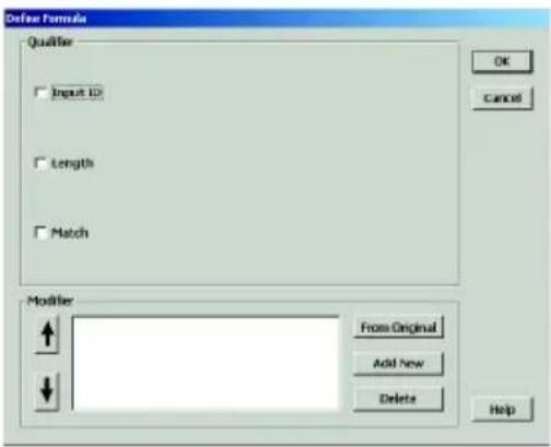
Qualifier
The Qualifier section defines the conditions that must be present for the scanned data to be modified, such as which symbology it must be (Codabar, Code 39, etc.), its specific length, or what characters (defined by a match string) the scanned data must contain.
When the conditions of the Qualifier are met, the data is then modified according to the rules defined in the "Modifier", below.
Modifier
The Modifier section contains three selections: "From Original", "Add New", and "Delete".
From Original extracts the desired data from the scan.
The Start Parameter defines the beginning of the string of data that is to be output. The start parameter can either be defined by position starting from the beginning ("From Position"), or a specific number of characters from the end of the string ("From Last Position"), or a specified number of characters before or after a user-defined character string ("After Matching").
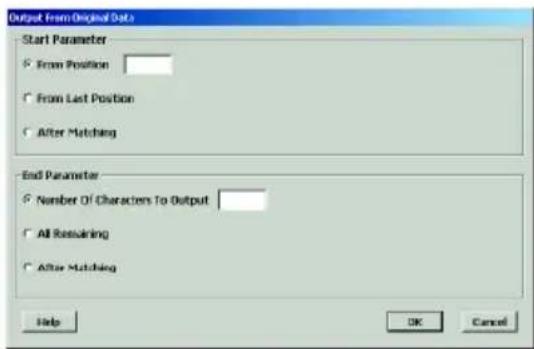
The End Parameter defines the end of the string of data that is to be output. Three options are available: "Number Of Characters To Be Output", "All Remaining", and "After Matching". The first two are self-explanatory. "After Matching" defines the end as a specified number of characters before or after a user-defined character string.
Data Editing, continued
Note:
Even if the original bar code data is not modified, if additional characters are to be added (see “Add New” below) the original Start Parameter must be defined as From Position “1” and the End Parameter defined as “All Remaining”, otherwise, none of the original data will be output.
Add New adds characters (printing and non-printing) to the data output from the MS860.
These characters can be added before, after, and within the actual scanned data. Pre-defined characters include:
Tab Carriage Return
•Line Feed Any Digit (data editing) - Any Letter (data editing)
- <*> Interblock Delay (data editing)
- <"> (quotation marks)
- Character in hexadeximal notation
- <<< < (less than)
-
(greater than)
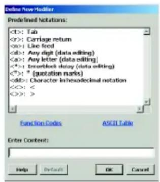
Characters must be bracketed by <> symbols.
Letters and numbers should be represented in hexadecimal format (accessible in a linked menu) to avoid confusion. For instance, the lower-case letter "t" should be entered as <74> and the numeral "5" should be entered as <35>.
Function codes (F keys, Cursor Up, Enter, etc.) can also be inserted via hexadecimal code (accessible in a linked menu).
Delete removes existing modifier strings.
Move Up / Move Down (pictured to the right) moves the modifiers up and down in relation to each other. The top modifier will be performed first and each one down the list will be performed in sequence. The original data (modified or unmodified, part or whole) will be output according to its position in the modifier sequence.
MS860 WiFi Manual

Data Editing, continued
Arrange Formulas
After the formulas have been created, they must be arranged in the optimum sequence by selecting formulas and using the "Move Formula" icons (see page 32). This sequence is usually according to their qualifier - from least likely to occur to most likely to occur.
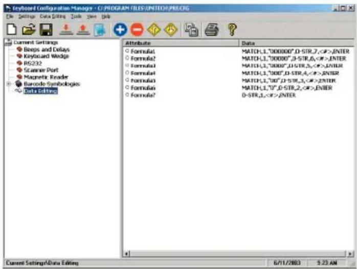
In the example pictured above, a series of formulas are designed to output all the data in a bar code that follows a series of “0”s. For instance, if the actual bar code data is “000045678”, the desired output would be “45678” (the original minus all the 0s at the beginning of the string). If there are six 0s (Formula 1 - pictured above), then Formula 1 specifies the output begins at the seventh position. If there are five 0s, then Formula 2 dictates that output begins at the sixth position, etc. If, instead, we were to place the qualifier for two 0s above (before) the qualifier for six 0s, then Formula 2 stipulating two 0s would activate even if there were six 0s because the qualifier would stop looking for 0s after it had found two. In this case, all qualifiers with three or more 0s would be disregarded, which would not be a desirable result.
The "Everything Else" Formula
If a formula is entered into the Data Editing Area, then all scanned bar codes will be evaluated according to this formula. If the scanned bar code does not satisfy the requirements of the Qualifier(s) (see page 57), then no data is output. Practically speaking, the scanner has been set up to scan only bar codes that are defined by the Qualifier(s). No other types of bar codes can be scanned.
The answer to this problem is to end the sequence of formulas with a formula that has no Qualifier and whose modifier includes all the scanned data (starts at position 1 and outputs “all remaining”). An example of this can be seen as Formula 7, pictured above.
Introduction
In addition to the Scanner Configuration Manager software, your MS860 scanner can also be configured via bar code input by scanning in the bar codes on the following pages.
The concept (for Groups 2 through 8) is fairly simple: Parameters are associated together into groups. For instance, on page 50, “Beep Tone”, “Interblock Delay”, and “Intercharacter Delay” form a group called “Beeps and Delays”.
In order to modify a particular parameter, first you must scan an “Enter Group X” bar code to start the procedure. For instance, to change the beep tone, first you must scan the “Enter Group 2” bar code. The scanner will emit a triple beep which indicates that the scanner has entered configuration mode. Also, the LED on the back of the scanner will start flashing green. The scanner will remain in configuration mode until the “Exit” bar code has been scanned.
Next, you must scan the bar code of the parameter (along the right-hand side of the page) you'd like to modify. To modify the beep tone, scan the "A1" label.
Then select a number along the left side of the page that corresponds with the modification you wish to make. To set the Beep Tone to "High", scan the "3" bar code. Please note that factory default settings are printed in bold face.
If you'd like to modify another parameter within the same group, scan another parameter label now. To change “Intercharacter Delay”, scan the “A3” bar code. then scan the number that corresponds with your requirements.
After you're finished modifying your selected parameters in "Beeps and Delays", scan the "Exit" bar code at the bottom of the page to end the modification session. The scanner will emit a double beep to indicate that it is no longer in configuration mode.
An easy alternative programming method is to simply scan the bar codes in the Quick Setup section starting on the next page, if appropriate.
The MS860 can always be reset back to “Factory Default” by scanning that particular bar code on page 62.
Note: Groups 9 and 10 (Data Editing and TCP/IP) do not follow the same steps as described above, but have their own sets of instructions in their respective sections.
Quick Setup Bar Codes
Device Type

AT Keyboard Wedge

USB

Wand Emulation

PS/2 Keyboard Wedge

IBM Terminal

Serial Interface

Macintosh

Keyboardless Wedge

Terminal Wedge
Inter-Character
Delay
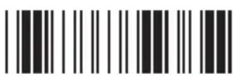
1 millisecond
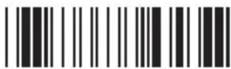
20 milliseconds
Code ID

No
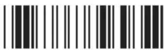
Yes
Scan Code

U.S.

Alt Key
Scanner Mode

Trigger
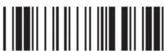
Flash
Beep
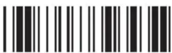
None

Medium
Terminator

Enter

Field Exit
MS860 WiFi Manual
PROGRAMMING VIA SCANNER INPUT
Quick Setup Bar Codes, continued
EAN-8

Default

Cut Leading Digit

Cut Check Digit
EAN-13

Default

Cut Leading Digit

Cut Check Digit

ISBN Conversion
Display Version

Display Version
MS860 WiFi Manual
Menu Setup

Enable / Disable
Supplemental Code

No

Yes
UPC-A

Default

Cut Leading Digit

Cut Check Digit
UPC-E

Default

Cut Leading Digit

Send Check Digit

UPC-A Conversion
Factory Default

Factory Default
PROGRAMMING VIA SCANNER INPUT
Beeps and Delays

Enter Group 2
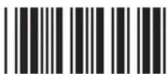
Group Default
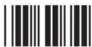
0
Beep Tone:
(see page 40)
0 - None
1 - Low
2 - Medium
3 - High
4 - Low to High
5 - High to Low
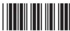
A1
1
2

3
4

5

6
7

8

9
Interblock Delay:
(see page 40)
0 - 0 ms
1 - 10 ms
2 - 50 ms
3 - 100 ms
4 - 500 ms
5 - 1 second
6 - 3 seconds
7 - 5 seconds

A2
Intercharacter Delay:
(see page 40)
0 - 0 ms
1 - 1 ms
2 - 2 ms
3 - 5 ms
4 - 10 ms
5 - 30 ms
6 - 50 ms
7 - 100 ms

A3

Exit
MS860 WiFi Manual
PROGRAMMING VIA SCANNER INPUT
Keyboard Interface
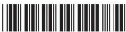
Enter Group 3

Group Default
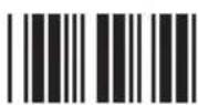
0
Function Code:
(see page 41)
0 - Off
1 - On
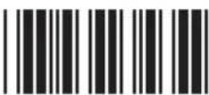
B1
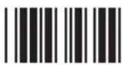
1

2
Caps-Lock:
(see page 41)
0 - Auto Trace (PC/AT)
1 - Lower Case
2 - Upper Case

B2

3

4
Language for PC/AT:
(see page 41)
0 - U.S.
1 - U.K.
6 - Italian
2 - Swiss
7 - German
3 - Swedish
8 - French
4 - Spanish
9 - Alt Key Mode
5 - Norwegian
:- Danish
B3

5
6
7
Use Number Keypad Digits:
(see page 41)
0 - Disable
1 - Enable

B8
8

9
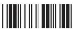
:
MS860 WiFi Manual
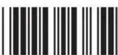
Exit
PROGRAMMING VIA SCANNER INPUT
RS232
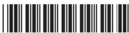
Enter Group 4
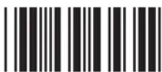
Group Default
0
Baud Rate:
1
(see page 42)
| 0 - 300 | 4 - 4800 |
| 1 - 600 | 5 - 9600 |
| 2 - 1200 | 6 - 19200 |
| 3 - 2400 | 7 - 38400 |

C1
2
Parity:
| (see page 42) | |
| 0 - Even | 3 - Space |
| 1 - Odd | 4 - None |
| 2 - Mark | |

C2

3
Data Bit:
| (see page 42) |
| 0 - 7 |
| 1 - 8 |

C3
4
Handshaking: (for serial wedge)
(see page 42)
0 - Ignore
| 1 - RTS enabled at Power Up |
| 2 - RTS enabled in Communication |

C4

5
ACK/NAK: (for serial wedge)
| (see page 42) |
| 0 - Off |
| 1 - On |

C5

6

7
MS860 WiFi Manual

8

9
PROGRAMMING VIA SCANNER INPUT
RS232, continued
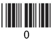 | BCC Character: (for serial wedge)(see page 43)0 - Off1 - On | 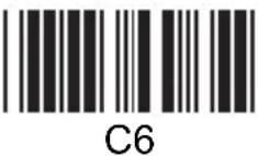 |
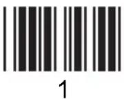 | Time Out: (for serial wedge)(see page 43)0 - 1 second1 - 3 seconds2 - 10 seconds3 - Unlimited | 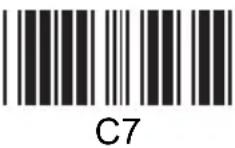 |
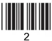 | ||
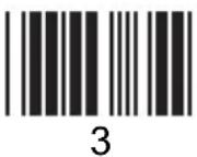 | Data Direction: (for terminal wedge)(see page 43)0 - Send to Host1 - Send to Host and Terminal2 - Send to Terminal | 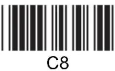 |
 | ||
 | ||
 | ||
 | ||
 | ||
 |  | |
| MS860 WiFi Manual | 66 |
PROGRAMMING VIA SCANNER INPUT
Scanner Port
Enter Group 5
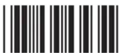
Group Default

0
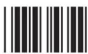
1

2

3
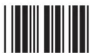
4

5

6
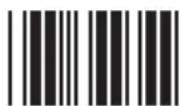
7

8

9
Terminator:
(see page 44)
0 - Enter
1 - Return (on keypad)
2 - Field Exit or Right Ctrl
3 - None
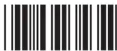
D1
Code ID:
(see page 45)
0 - Disable
1 - Enable
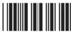
D2
Note: This setting does not affect EAN 128
Code ID. EAN 128 has its own Code ID setting (see page 51).
Define Code ID:
(see page 45)
00 - Code 39 Full ASCII
01 - Code 39 Standard
02 - EAN-13
03 - UPC-A
04 - EAN-8
05 - UPC-E
06 - Interleaved 2 of 5
07 - Codabar
08 - Code 128
09 - Code 93
10 - Standard 2 of 5
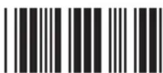
D3
11 - MSI Code
12 - EAN 128
13 - Code 32
(Italian Pharmacy)
14 - Delta Code
15 - Label Code
16 - Plessey Code
17 - Code 11 (Special)
18 - China Postal Code (Toshiba Code)

Exit
MS860 WiFi Manual
PROGRAMMING VIA SCANNER INPUT
Scanner Port, continued
| Double Verification:(see page 45)0 - Off1 ~ 7 - On (verify 1 to 7 times) | 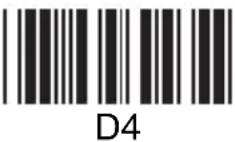 |
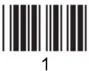 | Scanning Mode:(see page 46)0 - Trigger1 - Flashing2 - Multiscan3 - One Press One Scan4 - Test Mode5 - Old Laser Flash Mode6 - Continuous | 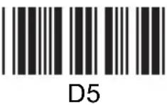 |
| ||
 | ||
 | Label Type:(see page 46)0 - Positive1 - Positive and Negative | 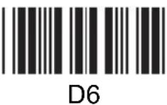 |
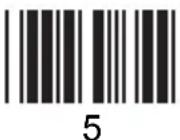 | Aim Function for LongRange Laser Engine:(see page 47)0 - Disable1 - Enable | 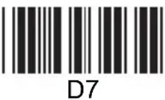 |
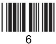 | ||
| Data Length (two digits) Send:(see page 47)0 - Disable1 - Enable |  |
 | ||
| | |
| MS860 WiFi Manual | 68 |
Scanner Port, continued
A Preamble can be inserted before, or a
Postamble can be inserted after the scanned bar code data (inserting a Tab, for instance).
To insert a postamble, scan the "Postamble" (OO) bar code, scan your selected postamble from the Function Code (page 82) or ASCII Code (pages 83 to 86) Charts, and then scan the "Postamble" (OO) bar code once again.
To insert a preamble, follow the same procedure, but using the "Preamble" (PP) bar code.
Preamble Postamble

PP
00
PROGRAMMING VIA SCANNER INPUT
Symbologies - Group 6
Enter Group 6
Group Default

0
1

2

3

4

5
6
7

8

9
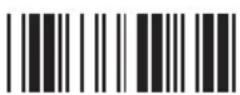
:
MS860 WiFi Manual
Code 39:
(see page 48)
0/1 - Disable / Enable
2/3 - Full ASCII / Standard
4 - Check Digit Calculate and Send
5 - Check Digit Calculate, Not Send
6 - Check Digit Not Calculate
7/8 - Send / No Send Start/Stop Sentinel
9/: - Double Labels Decoding Off / On
0 \~ 48 - Min. Length 0 / Max. Length 48
(see page 72 for Min./Max. Length procedure)

F1
Interleaved 2 of 5 (ITF):
(see page 49)
0/1 - Disable / Enable
2/3 - Fix Length On / Off (by first three reads)
4 - Check Digit Calculate and Send
5 - Check Digit Calculate, Not Send
6 - Check Digit Not Calculate
7 - Supress First Digit
8 - Supress Last Digit
9 - Last Digit Not Suppressed
2 \~ 64 - Min. Length 10 / Max. Length 64
(see page 72 for Min./Max. Length procedure)

F2

Exit
PROGRAMMING VIA SCANNER INPUT
Symbologies - Group 6, continued

0
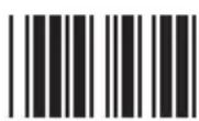
1

2
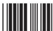
3

4
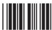
5

6

7

8

9
Standard 2 of 5 /
China Postal Code /
Toshiba Code:
(see page 50)
0/1 - Disable / Enable
2/3 - Fix Length On / Off (by first three reads)
4 - Check Digit Calculate and Send
5 - Check Digit Calculate, Not Send
6 - Check Digit Not Calculate
1 \~ 48 - Min. Length 4 / Max. Length 48
(see next page for Min./Max. Length procedure)
Code 32 (Italian Pharmacy):
(see page 51)
0/1 - Disable / Enable
2/3 - Leading Character
Send / No Send
4/5 - Tailing Character Send / No Send
Telepen:
0/1 - Disable / Enable
2/3 - Standard / Numeric Set

F3

F4

F5
UCC/EAN 128:
(see page 51)
0/1 - Disable / Enable
2/3 - Code ID Disable / Enable
Note: If EAN 128 is disabled, EAN 128 labels will be decoded as Code 128

F6

Exit
MS860 WiFi Manual
PROGRAMMING VIA SCANNER INPUT
Symbologies - Group 6, continued
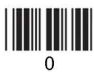
Define the EAN 128 Fields Separator:
Scan from the ASCII Code Chart (pages 83 to 86) to define a new fields separator.
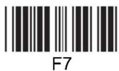
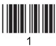
Define a Separator for Double Labels:
Scan from the ASCII Code Chart (pages 83 to 86) to F8 define a new separator for Double Labels.
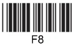
Define Minimum and Maximum Length:
To define minimum or maximum acceptable bar code data length, after scanning the parameter code (F1, F2, or F3), scan the "MM" or "NN" bar codes below, scan the number(s) to the left, and then scan the "MM" or "NN" bar code again. Then scan "Exit" as usual.
Min. Length
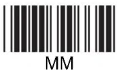
Max. Length
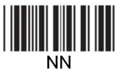
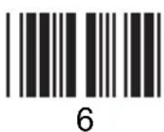
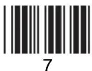
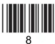
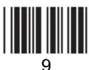
MS860 WiFi Manual
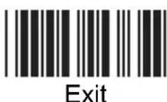
PROGRAMMING VIA SCANNER INPUT
Symbologies - Group 7
Enter Group 7
Group Default
0
Code 128:
(see page 51)
0/1 - Disable / Enable
1 \~ 64 - Min. Length 1 /
Max. Length 64
(see page 72 for Min./Max. Length procedure)

G1
1
2

3
4

5
6
7

8

9
MSI / Plessey Code:
(see page 52)
0/1 - Disable / Enable
2/3 - Check Digit Send /
No Send
4 - Check Digit Double Module 10
5 - Check Digit Module 11 Plus 10
6 - Check Digit Single Module 10
1 \~ 16 - Min. Length 1 / Max. Length 16
(see page 72 for Min./Max. Length procedure)

G2
Code 93:
(see page 52)
0/1 - Disable / Enable
1 \~ 48 - Min. Length 1 /
Max. Length 48
(see page 72 for Min./Max. Length procedure)
G3

Exit
MS860 WiFi Manual
PROGRAMMING VIA SCANNER INPUT
Symbologies - Group 7, continued
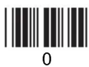
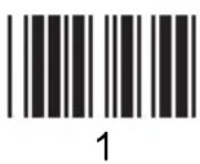
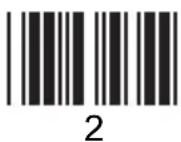
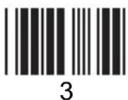
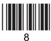
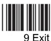
MS860 WiFi Manual
Code 11 (Special):
(see page 55)
0/1 - Disable / Enable
2/3 - One / Two Check Digit
4/5 - Check Send / No Send
1 \~ 48 - Min. Length 1 / Max. Length 48
(see next page for Min./Max. Length procedure)
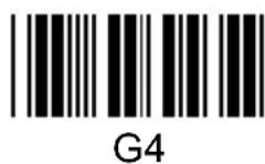
Codabar:
(see page 53)
0/1 - Disable / Enable
2/3 - Start & Stop Send /
No Send
4 - Check Digit Calculate and Send
5 - Check Digit Calculate but Not Send
6 - Check Digit Not Calculate
7/8 - CLSI Format On / Off
3 \~ 48 - Min. Length 3 / Max. Length 48
(see next page for Min./Max. Length procedure)
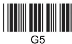
Label Code IV and V:
(see page 56)
0/1 - Disable / Enable
2/3 - Checksum Send / No Send
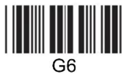

Symbologies - Group 7, continued
Define Minimum and Maximum Length:
To define minimum or maximum acceptable bar code data length, after scanning the parameter code (G1 to G5), scan the "MM" or "NN" bar codes below, scan the number(s) to the left, and then scan the "MM" or "NN" bar code again. Then scan "Exit" as usual.

Min. Length
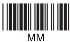
Max. Length
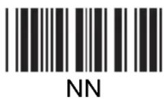

PROGRAMMING VIA SCANNER INPUT
Symbologies - Group 8
Enter Group 8
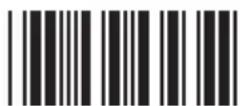
Group Default
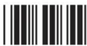
0
UPC-A:
(see page 53)
0/1 - Disable / Enable
2/3 - Leading Digit Send / No Send
4/5 - Check Digit Send / No Send

H1
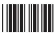
1

2
UPC-E:
(see page 54)
0/1 - Disable / Enable
2/3 - Leading Digit Send / No Send
4/5 - Check Digit Send / No Send
6/7 - Zero Expansion On / Off
8/9 - Disable / Enable NSC=1
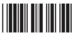
H2

3

4
5
EAN-13:
(see page 54)
0/1 - Disable / Enable
2/3 - Leading Digit Send / No Send
4/5 - Check Digit Send / No Send
6/7 - Bookland EAN (ISBN) Enable / Disable
H3
6

7
EAN-8:
(see page 55)
0/1 - Disable / Enable
2/3 - Leading Digit Send / No Send
4/5 - Check Digit Send / No Send

H4

8

9
MS860 WiFi Manual

Exit
PROGRAMMING VIA SCANNER INPUT
Symbologies - Group 8, continued

0
1

2
3

4
5

6

7

8

9
Supplement Code:
(see page 56)
0/1 - Two Supplement Code Off / On
2/3 - Five Supplement Code Off / On
4 - Transmit if Supplement Code is present (even if Two/Five Supplement Code is on)
5 - Transmit only if Supplement Code is present (if Two/Five Supplement Code is on)
6/7 - Insert Space Separator / Not Insert
Delta Distance Code:
(see page 55)
0/1 - Disable / Enable
2/3 - Leading Digit Calculate / Not Calculate
4/5 - Check Digit Send / No Send
H5

H6

Exit
MS860 WiFi Manual
Data Editing
Data Editing allows you to manipulate the bar code data output into the format that you require by scanning the bar codes on page 82 in addition to Function Codes and ASCII Codes on pages 83 to 76.
After scanning the “Enter Group 9” bar code, all the subsequent bar code input (except character string units) beginning with “IN_ID” must be separated by scanning comma bar codes, until you scan the final “Enter” followed by the “Exit” bar code. The “Enter Group 9” and the “Enter” bar codes are not followed by commas.
Parameters are grouped into Qualifiers and Modifiers.
Qualifiers specify the conditions that must be met in order for data editing to occur, be it minimum or maximum data length, specific symbologies, or specific character strings present.
Modifiers modify the data output according to pre-set rules by either removing specified parts of the data or adding user-defined data.
When programming the scanner, qualifiers must precede modifiers.
Each programming parameter is output according to the following patterns:
Qualifiers:
Input ID - Specific bar code symbologies can be selected for special treatment. The programming bar codes must be entered in the following sequence: IN_ID, ID1, ID2,...IDX, - where "IN_ID" announces that the next bar code inputs refer to the various bar code symbologies according to their "Code Type" on page 75. For example, if UPC-A and Code 32 bar codes are to be singled out for data editing, the bar code scanning sequence should be "IN_ID, 3, 13."
Length - Bar codes of specific length can be selected. The programming bar codes must be entered in the following sequence: LEN,MIN,MAX, - where "LEN" announces that the next bar code inputs refer to the minimum and maximum length bar codes allowable. For example, if we only want data editing to apply to bar codes between 9 and 12 characters long, then the bar code scanning sequence should be "LEN,9,12,".
Match - Bar codes with specific character strings can be selected. The programming bar codes must be entered in the following sequence: MATCH,P1,"S1",P2,"S2",...PX,"SX",- where "MATCH" announces that the next bar code inputs will define where in the data a specific string will be located, and what characters the string consists of, surrounded by quotation marks. For example, if the bar code to be selected requires the string "efgh" beginning at the 3rd position, the bar code scanning sequence should be "MATCH,3,"efgh",". If we're looking for "efgh" anywhere within the bar code, the sequence should be "MATCH,"efgh",", with the "*" character signifying that it could be anywhere in the string.
Data Editing, continued
Note: Once a Qualifier is specified, other bar codes that do not meet the requirements of the Qualifier will be disregarded.
If you would like bar codes not specified by the Qualifier to output normally, simply add another qualifier that specifies all bar codes (19), starting at position 1, and outputting all remaining (#). (See example at the bottom of this page.)
Modifiers:
Original Data - Part or all of the original data string can be selected. The programming bar codes must be entered in the following sequence:
O-STR,P,N, - where "O-STR" announces that the next bar code inputs refer to where the output should begin and how many characters should be output. For example, if 7 characters are to be output beginning with the 4th character, the bar code scanning sequence should be "O-STR, 4,7". If we want all the characters after the 4th character to be output, the sequence should be "O-STR,4,#," with the "#" character signifying that the entire string (after the 4th character) should be output. Should you decide that the last two characters should not be output, the sequence would be ""O-STR,4,#-2," with the "#-2" specifying all remaining minus 2.
Special Characters
, Comma - Used as a separator between formula parameters, beginning with the IN_ID parameter and ending with the Enter parameter.
“ Quotation Mark - Used to begin and end a character string. A character string bounded by quotation marks is treated as a single unit, and would be written as “abcd”.
* Asterisk - Wild-card character used to specify any digit or position.
Hash sign - Wild-card character used to specify any letter or last position.
Finally, end the programming sequence with the "Enter" bar code. Do not follow it with a comma. If you need to add another formula, do so now by scanning the "IN_ID" bar code directly, followed by the rest of the second formula's parameters, and then "Enter" again. Lastly, scan the "Exit" bar code.
Thus, if we want to output just the first five characters only from UPC-A input and then follow it with three "0"s, the scanning sequence should be as follows:
Enter Group 9 IN_ID, 3, O-STR, 1, 5, "000", Enter Exit
If we only want to treat UPC-A this way, but still want other symbologies to output normally, the scanning sequence would be as follows:
Enter Group 9 IN_ID, 3, O-STR, 1, 5, "000", Enter IN_ID, 19, O-STR, 1, #, Enter Exit
PROGRAMMING VIA SCANNER INPUT
Data Editing, continued
Enter Group 9
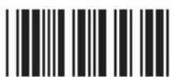
Group Default

0
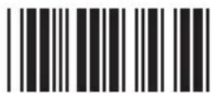
IN_ID

1

LEN
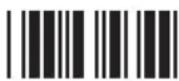
2

MATCH

3

O-STR

4

“
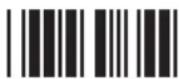
5

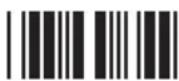
6

Enter

7

Backspace

8

,
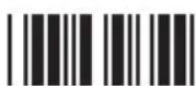
9

Exit

+

Review
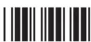
MS860 Manual
PROGRAMMING VIA SCANNER INPUT
TCP/IP
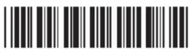
Enter Group 10
For TCP/IP instructions, see page 17.
CAUTION
Stop the VCOM connection before configuring the TCP/IP settings for the MS860 scanner.
Before configuring TCP/IP, power off the scanner, and then scan "Enter Group 10" within the first 5 seconds after switching the scanner back on.
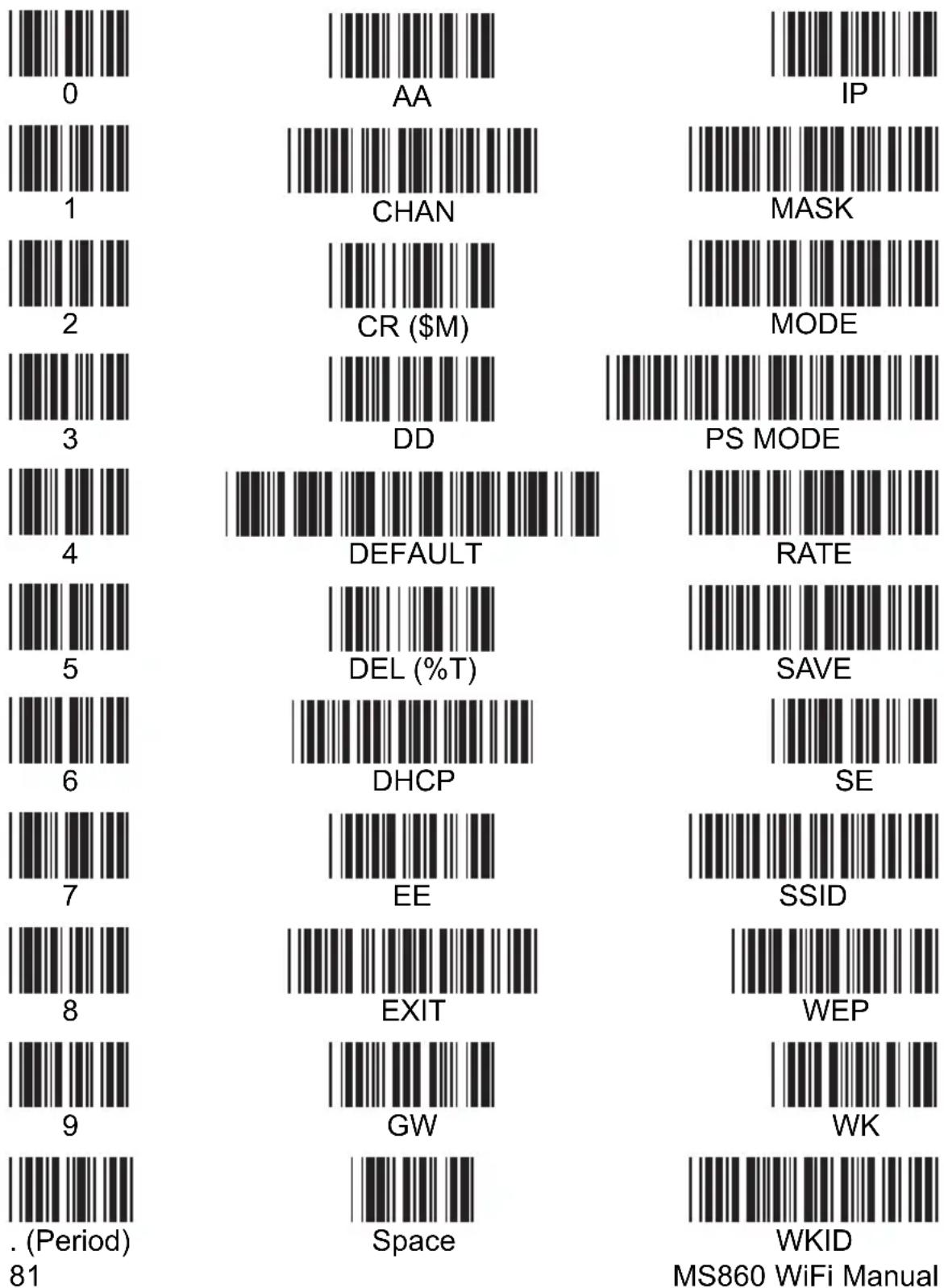
MS860 WiFi Manual
Function Codes for PC
(Characters in parentheses represent Code 39 bar code printing.)

F1 (%VA)
F12 (%VL)

Left Enter (/FL)

F2 (%VB)

Cursor Right (/FC)

Right Enter (/FM)

F3 (%VC)

Cursor Left (/FD)

Right Ctrl (/FO)

F4 (%VD)

Cursor Up (/FE)

Shift Make (/FP)

F5 (%VE)

Cursor Down (/FF)

Ctrl Make (/FQ)

F6 (%VF)

Page Up (/FG)

Alt Make (/FR)

F7 (%VG)

Page Down (/FH)

Shift Break (/FS)

F8 (%VH)

Tab (/FI)

Ctrl Break (/FT)
F9 (%VI)

Back Tab (/FJ)

Alt Break (/FU)

F10 (%VJ)

Esc (/FK)

Insert (/FW)
F11 (%VK) Delete (/FX)
MS860 WiFi Manual
PROGRAMMING VIA SCANNER INPUT
ASCII Chart
(Characters in parentheses represent Extended Code 39.)
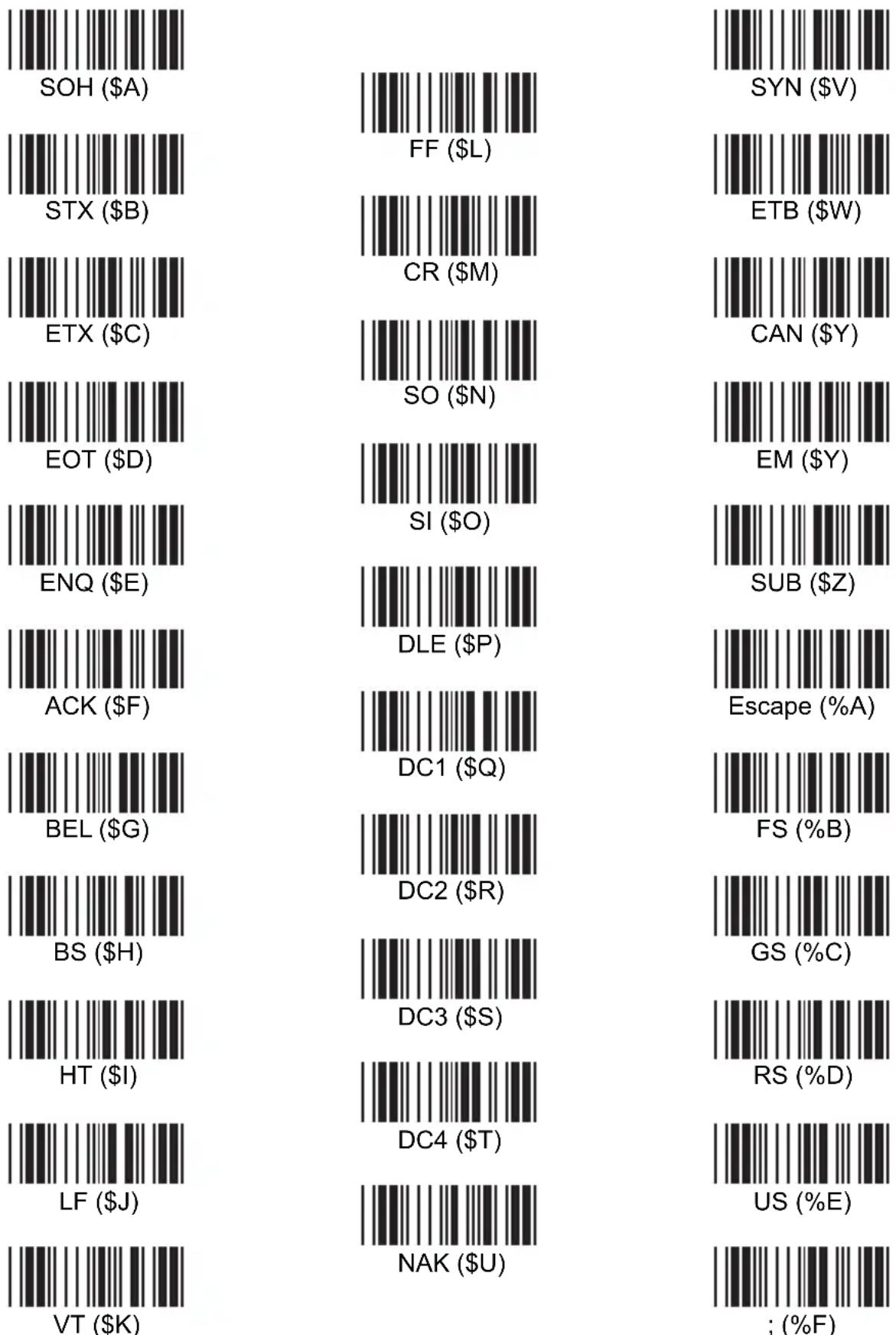
PROGRAMMING VIA SCANNER INPUT
ASCII Chart, continued
(Characters in parentheses represent Extended Code 39.)
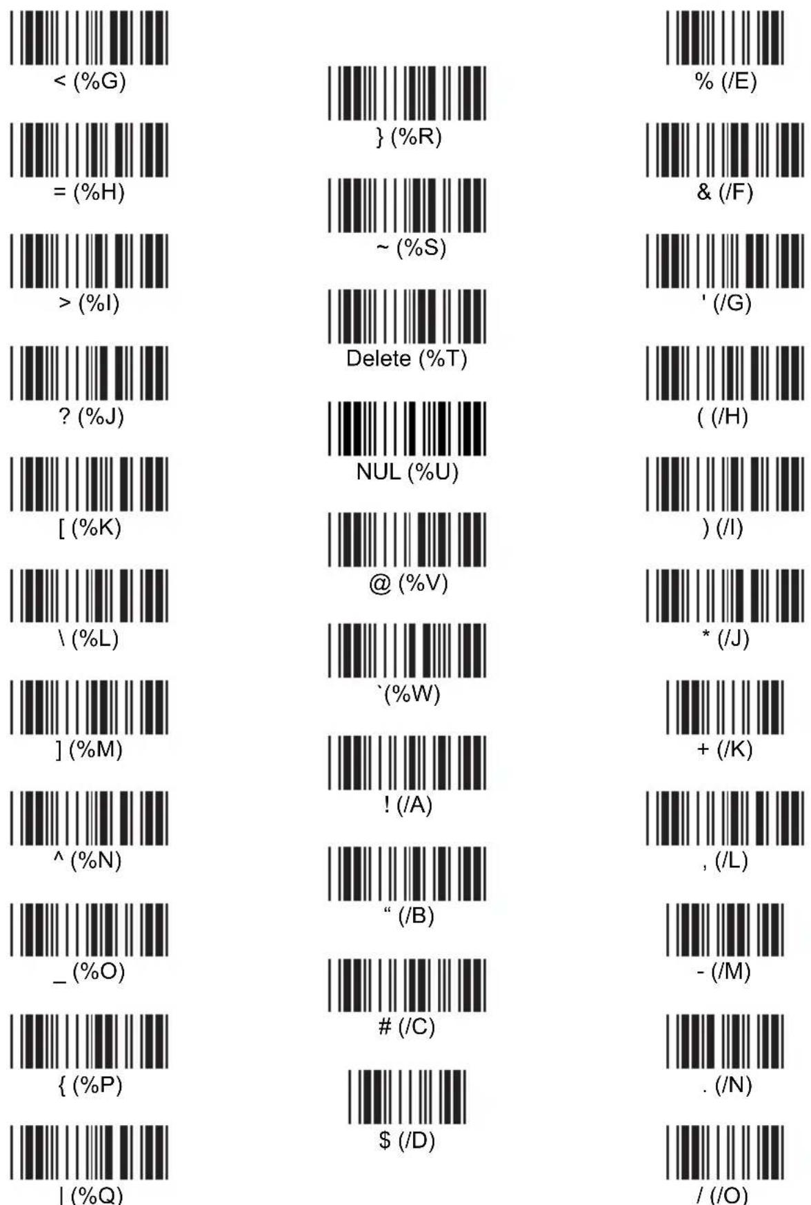
MS860 WiFi Manual
PROGRAMMING VIA SCANNER INPUT
ASCII Chart, continued
(Characters in parentheses represent Extended Code 39.)
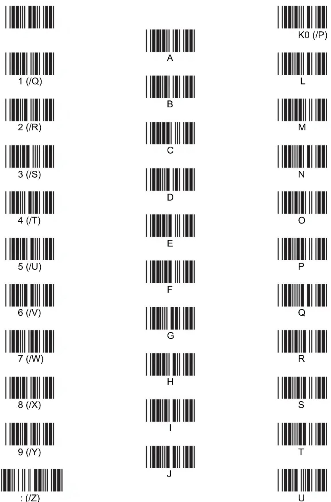
PROGRAMMING VIA SCANNER INPUT
ASCII Chart, continued
(Characters in parentheses represent Extended Code 39.)
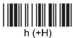
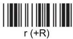
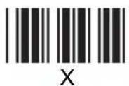
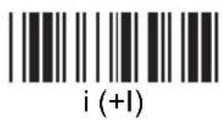
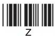
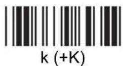
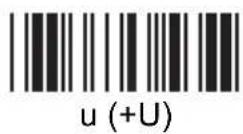
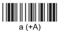
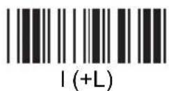
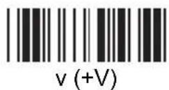
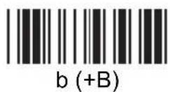
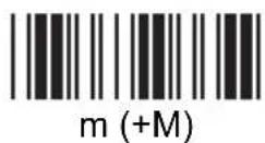
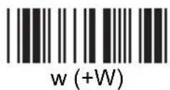
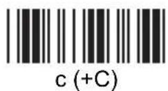
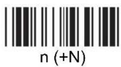
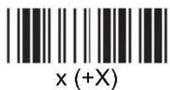
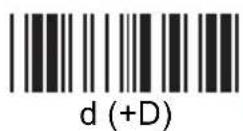
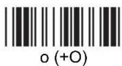
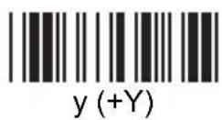
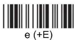
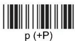
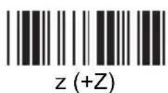
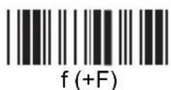
MS860 WiFi Manual
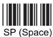
SPECIFICATIONS
PERFORMANCE
Receiving Device: SE 1200WA Scan Engine
Light Source: Visible Laser Diode - 650nm
Resolution: 4 mils (.01mm) min.
Scan Rate: 30 to 40 scans per second
Skew Angle: ±55°
Pitch Angle: ±65°
Printing Contrast Scale: 20% minimum
Maximum Width of Field: 9" (230mm) (PCS=90%, 40mil code)
Reading Distance: Code 39 - 5mil
(DoF PCS=90%) 40 to 130mm (±10mm)
Code 39 - 6mil
35 to 150mm (±10mm)
JAN - 15.6mil
50 to 330mm (±30mm)
Code 39 - 40mil
30 to 760mm (±50mm)
DECODER
Symbologies: China Postal Code, Codabar, Code 11,
Code 32, Code 39 (Standard and Full
ASCII), Code 93, Code 128, Delta Code,
EAN-8, EAN-13, EAN 128, Interleaved 2
of 5, Italian Pharmacy, Label Code IV and
V, MSI Code, Plessey Code, Standard 2 of
5, UPC-A, UPC-E
Operation Mode: Trigger, Flash, Multiscan,
and One Press-One Scan
Interfaces: PS/2, RS232, TCP/IP
Configuration: Via Scanner Configuration Manager
software (downloadable from www.ute.com)
or bar code setup menus in manual
Data Editing: Almost unlimited
ELECTRICAL
Battery Type: Lithium-ion
Battery Capacity: 1900mAh - charged via cradle
Battery Charging Time: Fully charged (4.2V) in 4 to 5 hours
Operating Time: 16 hours
Cradle Power: Via a separate 9VDC / 2A power supply
SPECIFICATIONS
MECHANICAL
Scanner Dimensions: Length - 5" (126mm)
$$ \text { Width } = 3. 2 5 ^ {\prime \prime} (8 3 \mathrm{mm}) $$
$$ \text { Height } = 5. 6 2 5 ^ {\prime \prime} (1 4 3 \mathrm{mm}) $$
Cradle Dimensions: Length - 8.125" (206mm)
$$ \text { Width } = 3. 8 1 2 5 ^ {\prime \prime} (9 7 \mathrm{mm}) $$
$$ \text { Height } = 2. 2 5 ^ {\prime \prime} (5 7 \mathrm{mm}) $$
Scanner Weight: 11 oz. (312 grams)
Cradle Weight: 14.5 oz. (410 grams)
ENVIRONMENTAL
Temperature: Operating: 32^ to 122^ F ( 0^ to 50^ C)
-4° to 140° F (-20° to 60° C) Storage:
Humidity: 5% to 95% RH non-condensing
Mechanical Shock: 5 foot (1.5M) drop to concrete
ESD Protection: 8K Contact and 12K Air
COMMUNICATION
Radio Frequency: 2.4GHz compliant 802.11b protocol
Scalability: Point to point, multi point
Range: 30M line of sight
WLAN Default Settings:
| Item | Default Setting |
| IP Address | 192.168.1.250 |
| IP Subnet Mask | 255.255.255.0 |
| Gateway IP Address | 192.168.1.254 |
| SSID | Wlandemo |
| RF Channel | 6 |
| WEP | Disabled |
| Authentication Type | Auto |
RS232 Default Settings:
| Item | Default Setting |
| Baud Rate | 38400 |
| Data Length | 8 (fixed) |
| Parity | None (fixed) |
| Stop Bit | 1 (fixed) |
| Flow Control | None |
TROUBLESHOOTING
Generic Scanner Troubleshooting Tips
Most problems that you might encounter with your scanner can be solved using the following procedures:
- Try scanning other bar codes. If your scanner can scan other types of bar code symbologies, but cannot scan your bar codes, first check to see if your particular bar code symbology is enabled. If it is, try the scanner on the same bar code type in the Bar Code Test Chart in the back of this manual. Then, insure that your bar codes are crisp and clear.
- Reset to Factory Default. Scan the “Factory Default” bar code on page 62 to reset your scanner back to factory default. Caution: This procedure will erase special configurations that you would have created.
- Test the scanner on other ports. Unitech scanners are built to the highest standards, and a perceived scanner malfunction may actually be a malfunction in the host computer. Test the scanner on the host's other ports if possible or, in necessary, on other systems to verify that the problem is actually in the scanner and not in the host computer.
Problems and Solutions
Problem: Scanner doesn't light up.
If the scanner does not emit a light when the trigger is pressed, make sure the scanner is switched on (see page 5), and/or that the battery is charged (see page 8).
Problem: Scanner lights up but doesn't beep.
If the scanner emits a light, but doesn't beep when scanning a bar code, try bar codes of different symbologies. If other types of bar codes scan properly, then it might be that the scanner is not configured to scan your particular symbology.
If the scanner can scan other bar codes of the same symbology, then other parameters (such as minimum/maximum length, etc.) may have to be adjusted.
Insure that your bar code has been created properly, with crisp edges and start/stop sentinels. For instance, Code 39 bar codes require asterisk (*) start/stop sentinels at the beginning and end of the data string (*123ABC*).
Avoid glossy surfaces or glossy inks for your bar codes. A glossy black surface may be indistinguishable from a white surface to your scanner because of the reflected light. Try photocopying your bar code and scanning the copy to determine if glossiness may be a factor.
Problem: Scanner makes four high-low beeps when attempting to scan.
The scanner has not been properly configured. A full reset is required by scanning the “Factory Default” bar code (see page 62), and switching the scanner off and back on again (see page 2, item 4).
Problems and Solutions, continued
Problem: No output from scanner.
Try the scanner on other com ports (if available) or other computers to see if it's a hardware problem.
If the scanner appears to scan (emits a light and beeps), but does not output data, try scanning into a HyperTerminal session to see if it's an application problem. When testing your scanner in HyperTerminal, make sure that:
Bits per second = 9600
Data bits = 8
Parity = None
Stop bits = 1
Flow control = None
Problem: VCOM cannot connect to the MS860.
Step 1: Make sure the Access Point's "Data" LED is flashing green. Test the AP with input from other sources. Triple-check that all network settings match.Step 2:
Step 3: To verify that the COM# you are trying to use isn't already taken, do the following: Click Control Panel / System / Hardware / Device Manager. Click the + next to "Ports (COM & LPT).
You should see Communications Port (COM1) at least. Make sure that the com port number that you're trying to use in VCOM isn't already listed.
Step 4: Make sure ComtoKey is off or set to “Disable Com Port” before clicking “Start” in VCOM. Likewise, disable any other program that accesses a com port (like POS software, database input programs, etc.) because these will cause VCOM to fail by locking up the com port.
TROUBLESHOOTING
Problems and Solutions, continued
Step 5: Close VCOM and test the MS860's network connection as follows:
Open a DOS session (Start / Run / type "cmd").
Type "ping ##.##.##.##" (replacing # symbols with your MS860's actual IP address).
The results should be similar to that below:
Z:\>ping 10.0.0.68
Pinging 10.0.0.68 with 32 bytes of data:
Reply from 10.0.0.68: bytes=32 time=197ms TTL=128
Reply from 10.0.0.68: bytes=32 time=118ms TTL=128
Reply from 10.0.0.68: bytes=32 time=140ms TTL=128
Reply from 10.0.0.68: bytes=32 time=163ms TTL=128
Ping statistics for 10.0.0.68:
    Packets: Sent = 4, Received = 4, Lost = 0 (0% loss),
Approximate round trip times in milli-seconds:
    Minimum = 118ms, Maximum = 197ms, Average = 154ms
Z:\>
If no packets are found, try a few more times.
If the ping "times out" consistently, then the MS860 is not connected to the network and you need to start your setup over.
If 1 to 3 packets are received, then you are too far from the Access Point and have a weak connection. Steps to resolve this include:
Get closer to the Access Point.●
- If the AP has an antenna, get it as high in the air as possible.
- Disable the AP's Power Saving option (if it has one). Set the AP for maximum power usage (if possible).
Set the MS860's Power Saving mode to "off". - Concrete walls, large metal objects, etc. can impede the WiFi signal and should be accounted for and avoided.
BAR CODE TEST CHART
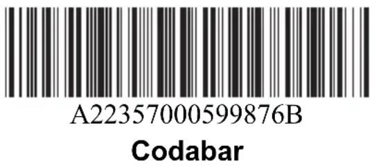
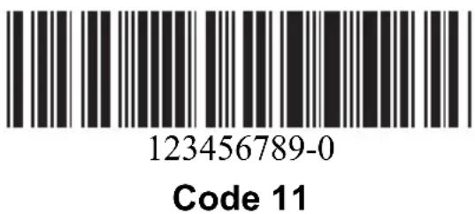
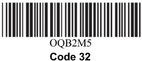
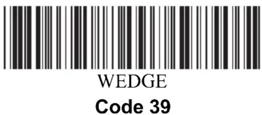

Code 39 with Check Digit
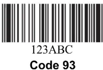
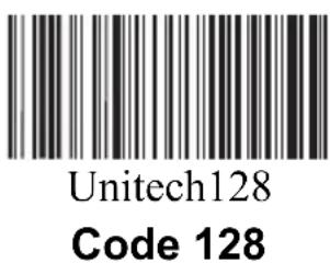
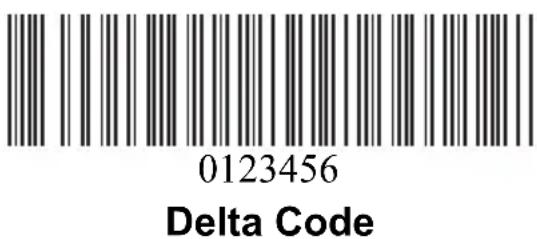
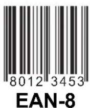
BAR CODE TEST CHAR
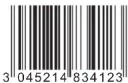
EAN-13
0987654321
Interleaved 2 of 5

10017
Label Code IV
1122334455
Standard 2 of 5
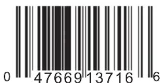
UPC-A
(01)054123456789(01)659344
EAN 128
957-630-239-0
ISBN

12345
MSI Code

20132000400
Toshiba Code
UPC-E
- Network Settings 9
- Scanner Configuration . . . . . . . . . . . . . . . . . . . . . 31
- Specifications 87
- Troubleshooting 89
- Bar Code Test Chart. 93
- INTRODUCTION
- QUICK START
- IMPORTANT NOTES
- COMPANY AND ACCESSORIES:
- SCANNER PARTS:
- Scanner LED
- Red LED is ON
- Single Green LED Flash
- Flashing Green LED
- Red LED Flash
- Buzzer
- One High Tone Beep
- One High-Low-High Beep
- Continuous High-Low Beeps
- CRADLE PARTS:
- Cradle LEDs
- Power ON/OFF Status LED stays ON
- Battery Charging Status LED remains Red
- Battery Charging Status LED remains Green
- Please Note:
- How to determine if the scanner needs recharging:
- To Charge the MS860:
- Manufacturer's Suggestion:
- NETWORK SETTINGS
- How the MS860 WiFi actually works:
- VCOM
- Modifying the WiFi settings:
- SCM
- Bar Codes
- GLOSSARY
- IP Address
- IP Subnet Mask
- Gateway IP Address
- SSID
- RF Channel
- WEP
- Authentication Type
- Alias
- Contact
- Location
- SNMP Community
- USING SCM FOR SCANNER NETWORK SETTING
- IMPORTANT:
- USING BAR CODES TO SET SCANNER NETWORK:
- WEP
- WKID
- WK
- AA
- PSMODE
- CHAN
- SAVE
- SE
- DEFAULT
- EXIT
- INSTALLING VIRTUAL COM
- START VIRTUAL COM:
- Configure the virtual com port using monitor.exe:
- Keep the default settings of the server port and server IP. NETWORK SETTINGS
- You should not change the Server port & Server if if you want to use the PC which run moniter.exe utility to act as the TCP server.
- Scan data and send data via WiFi:
- SCANNER CONFIGURATION MANAGER
- Start It Up
- Try It!
- Using SCM for scanner network setting:
- Beeps and Delays
- Beep Tone
- Wizard screen will appear. Interblock Delay
- Intercharacter Delay
- Keyboard Wedge
- Function Code
- Caps-Lock
- Language
- Use Numeric Keypad
- Baud Rate
- Parity
- Handshaking
- ACK/NAK
- BCC Character
- Time Out
- Data Direction
- Receive Terminator
- Scanner Port
- Terminator
- Scanner Port, continued
- Use Code ID
- Double Verification
- Settings
- Interblock Delay
- Keyboard Wedge, continued
- RS232
- Data Bit
- RS232, continued
- Scanning Mode
- Label Type
- Aim Function for Long Range Engine
- Aiming Time for Long Range Engine
- Preamble
- Postamble
- Bar Code Symbologies
- Code 39
- Bar Code Symbologies, continued
- Interleaved 2 of 5
- Standard 2 of 5 / Toshiba Code (China Postal Code)
- Code 32
- EAN 128
- Code 128
- MSI / Plessey Code
- Code 93
- Codabar
- UPC-A
- UPC-E
- EAN-13
- EAN-8
- Code 11
- Delta Code
- Supplement Code (for UPC-E, ISBN, EAN-13)
- Label Code IV and V
- Data Editing
- Qualifier
- Modifier
- Data Editing, continued
- Note:
- Delete removes existing modifier strings.
- Arrange Formulas
- The "Everything Else" Formula
- Quick Setup Bar Codes
- PROGRAMMING VIA SCANNER INPUT
- Quick Setup Bar Codes, continued
- Beep Tone:
- Interblock Delay:
- Intercharacter Delay:
- Keyboard Interface
- Function Code:
- Caps-Lock:
- Language for PC/AT:
- Use Number Keypad Digits:
- Terminator:
- Code ID:
- Define Code ID:
- Symbologies - Group 6
- Code 39:
- Interleaved 2 of 5 (ITF):
- Symbologies - Group 6, continued
- Define the EAN 128 Fields Separator:
- Define a Separator for Double Labels:
- Define Minimum and Maximum Length:
- Symbologies - Group 7
- Code 128:
- MSI / Plessey Code:
- No Send
- Code 93:
- Symbologies - Group 7, continued
- Code 11 (Special):
- Codabar:
- - Check Digit Not Calculate
- Label Code IV and V:
- Symbologies - Group 8
- UPC-A:
- UPC-E:
- EAN-13:
- EAN-8:
- Symbologies - Group 8, continued
- Supplement Code:
- Delta Distance Code:
- Qualifiers:
- Modifiers:
- Special Characters
- Hash sign - Wild-card character used to specify any letter or last position.
- TCP/IP
- CAUTION
- Function Codes for PC
- ASCII Chart
- ASCII Chart, continued
- SPECIFICATIONS
- PERFORMANCE
- DECODER
- ELECTRICAL
- MECHANICAL
- ENVIRONMENTAL
- COMMUNICATION
- TROUBLESHOOTING
- Generic Scanner Troubleshooting Tips
- Problems and Solutions
- Problem: Scanner doesn't light up.
- Problem: Scanner lights up but doesn't beep.
- Problem: Scanner makes four high-low beeps when attempting to scan.
- Problems and Solutions, continued
- Problem: No output from scanner.
- Problem: VCOM cannot connect to the MS860.
- BAR CODE TEST CHART
- BAR CODE TEST CHAR
Brand : Unitech
Model : MS860
Category : Barcode scanners