
MS146-IUCB0M-SG - Barcode scanners Unitech - Free user manual and instructions
Find the device manual for free MS146-IUCB0M-SG Unitech in PDF.


| Product Type | Barcode Scanner |
| Brand | Unitech |
| Model | MS146-IUCB0M-SG |
| Dimensions (Approx.) | 6.7 x 4.3 x 2.6 in (17 x 11 x 6.5 cm) |
| Weight (Approx.) | 6.5 oz (184 g) |
| Power Supply | 5V DC via USB, keyboard, or RS-232 cable; optional power adapter |
| Interfaces | Keyboard Wedge, RS-232, USB, Wireless Bluetooth (HID, SPP) |
| Scanning Technology | CCD or Laser (bi-color model supports both) |
| Reading Modes | Trigger, Continuous, Auto-Sensing, Flash, Test, Continuous Auto Off |
| Supported Symbologies | UPC-A/E, EAN-13/8, Code 39, Code 128, Codabar, Interleaved 2 of 5, MSI, PDF417, GS1 Databar, and many more |
| Indicator | Bi-color LED (Green/Red) and beeper |
| Cloning Mode | Yes, duplicates settings across multiple scanners |
| Wireless Range | Up to 100 m (line of sight) with Bluetooth |
| Battery (Wireless Model) | Rechargeable Li-ion, runtime approx. 8-10 hours |
| Data Storage (Memory Model) | 2 MB flash memory for batch mode |
| Operating Temperature | 0°C to 50°C (32°F to 122°F) |
| Storage Temperature | -20°C to 60°C (-4°F to 140°F) |
| Drop Specification | 1.5 m (5 ft) to concrete |
| Cleaning | Wipe with a soft, dry cloth; avoid solvents |
| Safety | Laser class 2; avoid direct eye exposure |
| Spare Parts / Repair | Replacement cables, power adapters, and stands available; service by qualified personnel |
Frequently Asked Questions - MS146-IUCB0M-SG Unitech
User questions about MS146-IUCB0M-SG Unitech
0 question about this device. Answer the ones you know or ask your own.
Ask a new question about this device
Download the instructions for your Barcode scanners in PDF format for free! Find your manual MS146-IUCB0M-SG - Unitech and take your electronic device back in hand. On this page are published all the documents necessary for the use of your device. MS146-IUCB0M-SG by Unitech.
USER MANUAL MS146-IUCB0M-SG Unitech
GENERAL
Table of contents....1
Preface, Ez Troubleshooting....2-3
Cloning Mode....4-5
How to fix the scanner to the terminal....6-7
How to change a cable....7
How to set up the parameter....8
SETTING GROUP(GROUP1\~14)
1 Interfaces selection, Computer type, Default, Setup Code ON/OFF....9
2 Reading Mode 10
Bi-color Setting 11
Advanced Autosensing Setting 12
13Advanced Autos
14-26Wireless Scanne
27Check Version,
3 27
4 Send Data Length, Preamble, Postamble....28
5 29Accuracy adjust
6 30Code ID, Label
7 31Symbologies Co
8\~9 Set Code ID, Customer Configuration......32-33
10 34Delay between I
11 Keyboard layout, Caplock Mode, Numeric Key.....35
12 RS232: Baud rate, Data bits, Parity.... 36
13 RS232: Stop bit, Handshaking, ACK/NAK, Flow Control, BCC.... 37
14 Wand Emulation parameter setting....38
SYMBOLOGY FORMATTING(GROUP15\~32)
15\~17 Enable/Disable Barcode Symbology...... 39-41
China postcode(Toshiba code)......417
18 MSI code, UK Plessey code....43
Code 93, Telepen, IATA....4f9
20 Interleaved 2 of 5, Code 11....47
21 Industrial 2 of 5, Matrix 2 of 5....49
22 Codabar....51
23 ABC Codabar, CX Codabar....53
24 Codabar Coupling....54
25 Code 39 (Full ASCII/Standard), Code 32......55
26 UPC-E....57
27 UPC-E(0)&(1), UPC-E EXPAND....58
28 UPC-A....59
29 EAN-8....60
30 EAN-13, ISSN, ISBN, ISMN....61
31 EAN/UCC 128, Code 128, PDF417....62
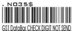
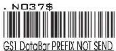
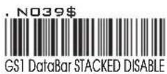
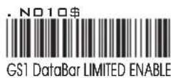
32 DataBar(RSS) Stacked, Limited, Expanded......63
FULL ASCII(CODE39)TABLE, FUNCTION KEY TABLE(GROUP33\~47)
33\~41 Full ASCII table(Code 39)....64-72
42\~44 Function Key table(Code 39) for PC-AT.....73-75
45\~47 Trouble Shooting....76-78
APPENDIX
Appendix 1 Default table....79-82
Appendix 2 Cable Pin Assignment....83-84
Appendix 3 Barcode test chart....85-86
| No | Kind of Troubles | Symptoms | Solutions |
| 1 | Computer Type (Group 1) | Scanner seems to be performing as usual, but no data is being output. | 1. Unplug the cable from the host computer.2. Plug the cable back into the host computer.3. Set the scanner to the exact computer type immediately. |
| 2 | Interfaces Selection (Group 1) | The scanner does not scan when the trigger is depressed. | 1. Unplug the cable from the host computer.2. Plug the cable back into the host computer.3. Set the scanner to the correct interface. The cable needs to match the interface. |
| 3 | Setting Procedure have not completed ( Setting Need Triple Shot scanning )Group - 4, 5, 8, 9, 17, 18, 19, 20, 22, 23, 25, 31 | The scanner does not output data and beeps three times at every scan.This symptom indicates that a three-scan setting is not yet completed. Some settings take three scans to complete, they are:1. Preamble, Postamble (Group4)2. Accuracy Adjustment (Group5)3. Customer ID Configuration (Group 8 & 9)4. Min/Max Length (Group 17, 18, 19, 20, 21, 22, 25)5. ABC Codabar (Group 22 & 23)6. CX-Codabar (Group 22 & 23)7. Coupling Codabar (Group 22 & 23)8. EAN 128 (Group 31) | 1. Follow the procedures for these settings at the appropriate pages.2. The scanner will beep three times for an incomplete setting.3. Scan RESET to try a setting again. |
| 4 | Limitation of length of the bar code | The scanner is reading correctly, except for certain bar codes of a certain length. | Reset the Min/Max setting for the bar code symbology affected. |
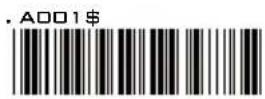
| 5 | Setup Code Disabled | When scanning the Default barcode, the scanner is not reset to Default but output data “A001$”. | Scan SETUP CODE ON(Group 1) to enable all setup codes. |
| 6 | RS232 Protocol Communication setting problem | The scanner appears to be working in the RS-232 interface, but no data is output. | Ensure the correct RS-232 communication parameters have been set: Baud Rate, Handshaking, Stop Bits, Data Bits, and Party. These settings must be the same for both the scanner and the host. |
CLONING MODE
WHAT IS CLONING MODE?
CLONING duplicates a scanners settings in other scanners. It can save time when a number of scanners must be programmed to the same settings.
HOW SHOULD CLONING WORK?
- Using this guide, make all the necessary settings for one wand.
- Scan the CLONING MODE bar code shown below.
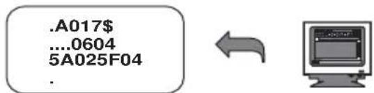
- When CLONING MODE is scanned, all setup parameters will be converted to alphanumeric characters and shown on the monitor.
- Using a bar code printer, print out all the setup parameters as Code 39 bar code labels.
- Scan the printed labels sequentially with each wand to be programmed.
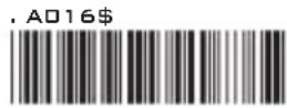
CLONING MODE
Figure 1
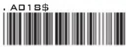
CLONING MODE ON-PC/AT
.A018\$(Cloning Mode on PC/AT) - you can clone the settings to a PC/AT regardless of the kind of device chosen on the scanner.
NOTES:
- All cloning strings are upper case.
- All cloning strings printed on labels should be the same as those on the monitor sequentially from first to last.
- Cloning mode works in Word Note Pad only.
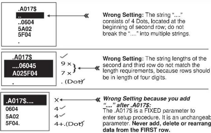
- Never edit the data on the first row (.A017\$). It is an entry command for cloning.
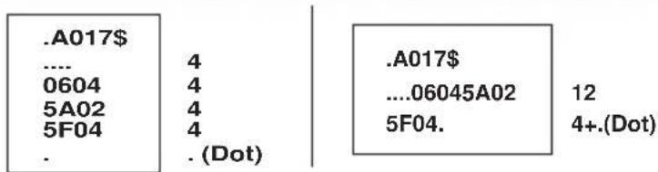
- The cloning string's length can be adjusted by combining multiple strings into one, or by breaking one string into multiple strings starting from the second row after “...”. Length must be in sequences of four, such as 4, 8, 12, 16, 20 (MAX).
- Be sure to print the dots exactly where they are shown on the monitor.
FORMAT OF CLONING
* Format of Cloning:
1st row >>> “.A017\$” ( never edit any data of the first row ) 2nd row >>> “....XXXX” you can adjust the String’s Length starting from the dots “...” forward. The length of the string should be in 4, 8, 12, 16 or 20 ( MAX )digits.
3rd row \~ so on >>> XXXX End row - A dot "." Is the ending of cloning.
XXXX Stands for any string
EXAMPLE :
1. PROJECT ASSIGNMENTS:
1.1. Beep tone: BEEP LOW -- HIGH.
1.2. Capslock Mode: CAPSLOCK ON.
1.3. Reading Mode: CONTINUOUS AUTO OFF.
2. SETTING PROCEDURE:
2.1. Scan BEEP LOW -- HIGH (GROUP 3).
2.2. Scan CAPSLOCK ON (GROUP 11).
2.3. Scan CONTINUOUS AUTO OFF (GROUP2).
- All parameters will be converted to alphanumeric characters and shown on the monitor.
- Print the results shown on the monitor as bar codes with a bar code printer. The bar codes should be in the Code 39 symbology.
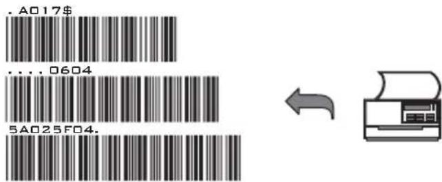
- Scan these labels with any of the wands that must be programmed with the same settings as the first wand. Be sure to scan from the first row to the second and so on sequentially, top to bottom.
CORRECT SETTING
WRONG SETTING
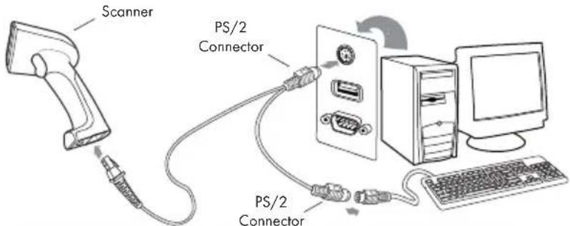
HOW TO CONNECT THE SCANNER TO THE HOST TERMINAL: Handheld Barcode Scanner
KEYBOARD WEDGE INTERFACE
- Power down the host computer.
- Disconnect the keyboard cable from the computer.
- Connect the "Y" cable between the keyboard and the scanner and computer.
- Restart the computer.
- The scanner will beep.
- Set the scanner to KEYBOARD interface by referring to GROUP 1 (Interfaces Selection)
- Scanner will beep to confirm the setting.
- Scan a bar code to confirm that data shows on the monitor.
RS-232 INTERFACE
- Power down the host computer.
- Disconnect the RS-232 cable between the scanner and computer.
- Connect the power adaptor to the cable.
- Restart the computer,
- Plug the power adaptor into a power outlet.
- The scanner will beep.
- Set the scanner to RS-232 interface by referring to GROUP 1 (Interfaces Selection).
- Set RS-232 protocol: Baud Rate, Stop Bits, Handshaking, Data Bits and Parity.
- Scan a bar code to confirm that data shows on the monitor.
NOTES:
- Before plugging the power adaptor into the scanner, be sure the voltage, power consumption, and inner and outer DC characteristics are correct to avoid serious damage to the scanner and/or the computer.
- Make sure the protocol communication settings of the scanner (such as baud rate, data bits, etc.) match those of the host computer. Otherwise, no data will be transmitted.
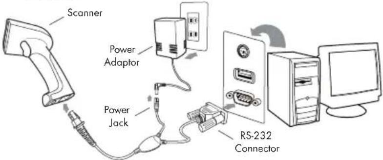
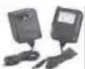
Check the power adaptor to ensure:
-
Input of AC current 110V/220V matches the power supply standard of the country in which the scanner is being used.
-
Adaptor output is +5V DC
-
The jack input is +5V DC

USB INTERFACE
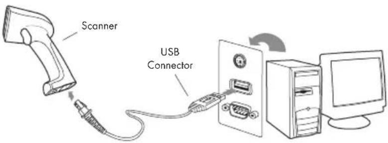
The USB Interface supported is compatible with Apple MAC series, later PCs and Windows 98, 2000, Me and XP, Vista.
- Connect the USB cable between the scanner and the computer.
- The scanner will beep.
- The scanner will detect the USB driver automatically. (The first time the scanner is connected via the USB port, follow the appropriate instructions for the host computer.)
- Set the scanner to KEYBOARD/USB interface by referring to GROUP-1 (Interfaces Selection)
- Scanner will beep to confirm the setting.
- Scan a bar code to confirm that data shows on the monitor.
HOW TO CHANGE A CABLE
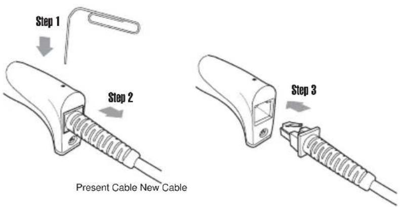
The scanners are designed to switch easily between interface options. To switch from one interface to another, the appropriate cable must be installed. To change a cabl, simply follow these steps:
- To release the cable, insert a pin or straightened paper clip into the hole at the base of the scanner where the cable is connected.
- Remove the cable from the scanner.
- Plug in the new cable.
After changing to a new cable, be sure to reset the interface setting as appropriate (including parameter settings for the RS-232 interface).
HOW TO SET PARAMETERS
How do you program a scanner with this user's guide?
- Use the scanner to scan at the bar code representing the function/parameter you want to set.
- When you hear two beeps, the new settings have been defined or updated into the memory processor.
Default parameters are indicated in bold type and underlined characters. The character font is ARIAL BLACK. CD = Check Digit. CDV = Check Digit Verification.
Most settings require only a single bar code, but a few need several different bar codes to be scanned in order to completely define a setting. They are:
natural_image
Line drawing of a mechanical bracket or housing component (no text or symbols)SETTING BAR CODE
Preamble / Postamble (maximum 16 digits)
Step 1: Scan CLR PRE/POSTAMBLE.
Step 2: Scan PREAMBLE or POSTAMBLE.
Step 3: Scan any alphanumeric from Full ASCII Table in Group 33-44
Step 4: Scan PREAMBLE or POSTAMBLE.
Min Length / Max Length
Step 1: Scan MIN LENGTH or MAX LENGTH.
Step 2: Scan two digits from Group 41 or Full ASCII numeric table in Appendix
Step 3: Scan MIN LENGTH or MAX LENGTH.
Accuracy Adjustment
Step 1: Scan ACCURACY ADJUSTMENT.
Step 2: Scan one digit from GROUP 5
Step 3: Scan ACCURACY ADJUSTMENT.
Set Code ID (Example: Code 39)
Step 1: Scan CODE 39 SET ID from Group 8
Step 2: Scan either one or two alphanumerics (maximum 2 digits) from Full ASCII table in Group 35-41
Step 3: Scan CODE 39 SET ID from Group 8
Set A Data - (CX-Codabar, ABC Codabar, Codabar Coupling).
Step 1: Scan SET INSERT DATA.
Step 2: Scan one alphanumeric character from Full ASCII Table in Group 35-41
Step 3: Scan SET INSERT DATA.
NOTES:
- The scanner will beep three times as a reminder that a setting is not yet complete.
- If you make a mistake, forget a step, etc., scan RESET to start again.
RESET
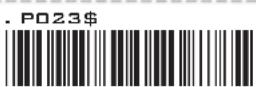
GROUP-1
INTERFACES SELECTION, COMPUTER TYPE, DEFAULT, SETUP CODE
DEFAULT
COMPUTER TYPE
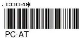
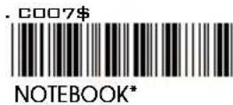
| SYMPTOMS SOLUTION | |
| Scanner seems to be performing as usual, but no data is being output. | 1. Unplug the cable from the host computer.2. Plug the cable back into the host computer.3. Set the scanner to the exact computer type immediately. |
Caution: Please ensure the correct computer type is set when the scanner is attached to a new host computer. If set to Notebook, the scanner will operate with no external keyboard.
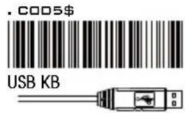
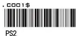
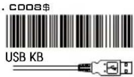
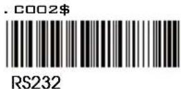
INTERFACES SELECTION
| SYMPTOMS | SOLUTION |
| The wand does not scan/ The scanner does not scan when the trigger is depressed. | 1. Unplug the cable from the host computer.2. Plug the cable back into the host computer.3. Set the wand to the correct interface. The cable needs to match the interface. |
Caution: This scanner is designed to switch easily between interface options. To switch from one interface to another, the appropriate cable must be installed. After changing to a new cable, be sure to reset the interface setting as appropriate.
SETUP CODE READ
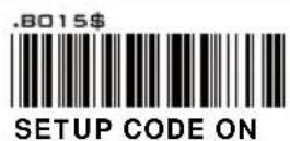
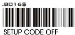
Caution: Scanning SETUP CODE OFF will turn the scanner into unprogrammable state and the scanner will not react to any setup code.
GROUP-2
READING MODE SETTING
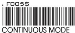
* LED is always on.
* The trigger does not function in Continuous Mode.
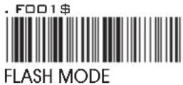
* The LED is on steady if a bar code is close to the scanner, but starts flashing if no bar code is detected after 60 seconds.
* The trigger does not function in Flash Mode.
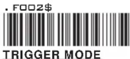
* The LED will light when the trigger is pressed.
* The LED will go off when the trigger is released.
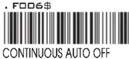
* The LED is always on when the trigger is pressed.
* The LED will go off if no bar code has been detected after 60 seconds.
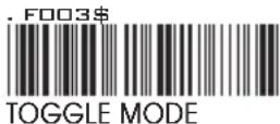
* This function works like Trigger Mode, but the scanner beeps to indicate a good read.
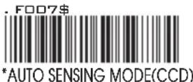
* If Auto-Sensing Mode(CCD) is on, the LED will go off if no bar code is detected after Deactivation Time elapses.(The default is 3 sec.)
* The LED lights automatically when a BAR CODE is detected.
* If Auto-Sensing Mode(CCD) is on, the Magnetic Switch and Blue LED will be activated at the same time.
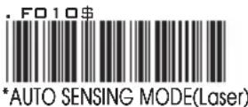
* If Auto-Sensing Mode(Laser) is on, the LED will go off if no barcode is detected after Deactivation Time elapses.(The default is 3 sec.)
* The laser emits automatically when an OBJECT is detected.
* If Auto-Sensing Mode(Laser) is on, the Magnetic Switch will be activated.
NOTES:
- To extend the scanner's life, keep the scanner set to Trigger Mode or Continuous Auto Off Mode.
- The LED indicator will glow for GOOD READ.
- For advanced settings of Auto-Sensing Mode(such as Deactivation Time, Magnetic Switch and Blue LED) please refer to the next pages.
GROUP-2.2
BI-COLOR LIGHT SOURCE SETTINGS
(The following settings are supported by Bi-Color models)
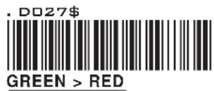
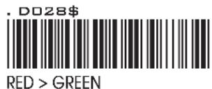
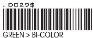
CYCLE MODE
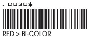
NOTES:
- Illumination color will switch back and forth from one to another when good read does not occur.
- Illumination color will remain as the one used at the last good read.
SINGLE MODE
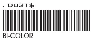
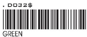
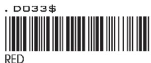
NOTES:
- Illumination color will remain single.
GROUP-2.3
ADVANCED AUTO-SENSING MODE SETTINGS
(The following settings are available after the activation of Auto-Sensing Mode)
MAGNETIC SWITCH (CCD & LASER SCANNERS)
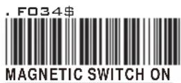
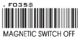
NOTES:
- The Magnetic Switch is automatically activated when Auto-Sensing Mode is on.
- To enable Magnetic Switch, the scanner should be paired with an Autosense Stand to perform Auto-Sensing function.
- When Magnetic Switch is disabled, the scanner will perform Auto-Sensing function without Autosense Stand.
- The green LED is automatically activated when Auto-Sensing Mode is on.
- Green LED serves as Supplement Light for a CCD scanner in order to enhance the sensitivity of scanner in Auto-Sensing Mode.
GROUP-2.4
ADVANCED AUTO-SENSING MODE SETTINGS
(The following settings are available after the activation of Auto-Sensing Mode)
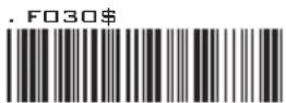
DEACTIVATION TIME
DEACTIVATION TIME (CCD & LASER SCANNERS)
NOTES:
- The default of Deactivation Time is 3 Sec.
- Deactivation Time is the time interval between the last scan and the automatic deactivation of LED or Laser light in Auto-Sensing Mode.
- You can set the Deactivation Time value by the following three steps:
Step 1: scan Deactivation Time
Step 2: scan two digits(Limit Range: 01 \~ 30sec.) from the Full ASCII numeric table.
Step 3: scan Deactivation Time
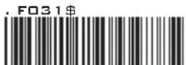
SAME CODE INTERVAL
- The default of Same Code Interval is 30 Sec.
- Same Code Interval is the time interval between two consecutive scans on the SAME bar code in Auto-Sensing Mode.
- You can set the value of Same Code Interval by the following three steps:
Step 1: scan Same Code Interval
Step 2: scan two digits(Limit Range: 03 \~ 60sec.) from the Full ASCII numeric table.
Step 3: scan Same Code Interval
IDLE MODE SETTING
IDLE MODE
Pre-Idle Time
Idle Mode On
Idle Mode Off
NOTES:
- Idle Mode is only supported by certain models.
- When Idle Mode is on, the scanner will enter idle state to save power after a period of inactivity, or Pre-Idle Time(the default is 1 min).
- You can set the value of Pre-Idle Time by the following four steps:
Step 1: scan Idle Mode On
Step 2: scan Pre-Idle Time
Step 3: scan one digits(Limit Range: 1\~9 Min.) from the Full ASCII numeric table.
Step 4: scan Pre-Idle Time
GROUP-2.5
WIRELESS SCANNER SETTINGS
LED & BEEPER INDICATION
| Scanner | Status | Blue/Green LED | Red LED | Beeper | Remark |
| Initializing/Power-up | Solid for 2 sec | 1 long beep | |||
| SuccessfulBarcodeScan | 1 Flash | 1 beep | |||
| SuccessfulConnection | 2 Flashes | 2 beeps | |||
| ReadsConfigurationBarcode | 2 short beeps | ||||
| DataTemporarilyStored | 1 Flash | High-Low beeps | See Batch Mode | ||
| DataPermanentlyStored | 1 Flash | Low-High beeps | See MemoryMode | ||
| WirelessDisconnection | Solid for 2 sec | 3 beeps | |||
| UnsuccessfulPincodeSetup | Flashing | 3 short beeps | Scan PincodeStop and retry | ||
| BarcodeScan w/oConnection | Flashing | 3 short beeps | |||
| Low Power | Flashing | 5 beeps | |||
| BarcodeScan w/oConnection | Flashing | Several shortbeeps | |||
| Power Offor Standby | See Power OffTimeout | ||||
| Cradle | Status | Blue LED | Red LED Green LED | Remark | |
| SuccessfulConnection | Solid | ||||
| Charging | Solid | Flashing | Power adaptorneeded | ||
| Full Charge | Flashing | 4 hours tofully charge | |||
GROUP-2.6
WIRELESS SCANNER SETTINGS
CONNECTION OPTIONS
. E041\$
BT mode - HID plug & play
- Connect the cradle to the host PC.
- Scan [DISCONNECT]
- Scan [BT mode - HID play & play], and the scanner will emit 8 beeps.
- Scan the Host Address barcode on the cradle's bottom.
- The scanner will beep twice and cradle's blue indicator LED will stay on to verify a successful connection.
*Note: Only supported by model with charging cradle.
. E040\$
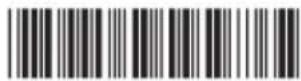
BT mode - HID non-pincode
- Press the trigger for 1 second to activate the scanner.
- Scan [DISCONNECT]
- Scan [BT mode - HID non-pincode]; the scanner will emit 8 beeps.
- Select "Wireless Scanner" from discovered device list.
- For PC, please click "Pair without using a code"
- The scanner will beep twice to verify the connection.
*Note: In this mode, the scanner is recognized by the host as a mouse (pointing device). If your host fails to find it, please try [BT mode - HID] instead.
.E042\$
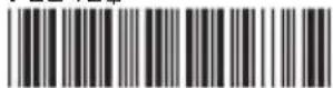
BT mode - SPP
- Press the trigger for 1 second to activate the scanner.
- Scan [DISCONNECT]
- Scan [BT mode - SPP]; the scanner will emit 8 beeps.
- Select "Wireless Scanner" from discovered device list.
- For PC, please click "Enter the device's pairing code".
- Enter "1234" from the host.
- Open serial communication software with com port (see Device Manager) properly set up.
- The scanner will beep twice to verify the connection.
. E043\$

BT mode - HID
- Press the trigger for 1 second to activate the scanner.
- Scan [DISCONNECT]
- Scan [BT mode - HID]; the scanner will emit 8 beeps.
- Select "Wireless Scanner" from discovered device list.
- For PC, please click "Create a pairing code for me"
- The Bluetooth application may prompt you to scan a pincode.
- Follow the steps in PINCODE SETUP section the on next page.
- The scanner will beep twice to verify the connection.
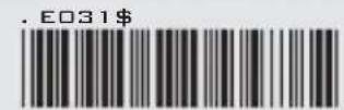
Disconnect
GROUP-2.7
WIRELESS SCANNER SETTINGS
PINCODE SETUP
STEP 1
Pincode Start
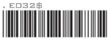
STEP 2
Scan numeric barcodes (see NUMERIC BARCODES below)
based on the pincode generated by the Bluetooth application.
NUMERIC BARCODES
| 1 | 6 | |
| 2 | 7 | |
| 3 | 8 | |
| 4 | 9 | |
| 5 | 0 |
STEP 3
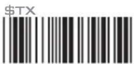
Enter
STEP 4
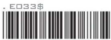
Pincode Stop
GROUP-2.8
WIRELESS SCANNER SETTINGS
SET BLUETOOTH DEVICE ID
To customize your own Bluetooth device name for the wireless scanner, please follow below steps:
STEP 1
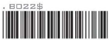
Default Wireless ID
STEP 2
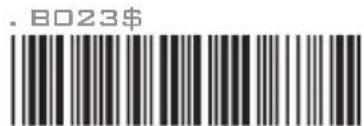
Set Wireless ID
STEP 3
Scan 7 alphanumeric characters from Full ASCII Table (GROUP 35-41)
STEP 4
Set Wireless ID
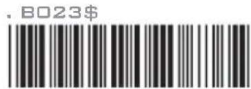
STEP 5
Scan a desired BT mode in Connection Option (GROUP 2.6) to complete the configuration.
\*Note:
- If you have connected the scanner with the host BEFORE customizing your Bluetooth device name, please remove the device and create a new connection to make sure device name is refreshed. For PC, it is recommended to restart the Bluetooth adaptor in order to refresh device name.
- At Step 3, the scanner will beep three times as an alert that more than 7 characters are entered.
- To reset the Bluetooth device name to default ("Wireless Scanner"), please simply do Step 1 & Step 5, skipping Step 2 to Step 4.
GROUP-2.9
WIRELESS SCANNER SETTINGS
POWER OFF TIMEOUT
The timeout before automatic power-off to save battery power.
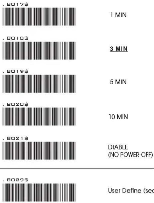
bar
| Item | Price ($) | Duration (Min) | | :--- | :--- | :--- | | .B017$ | 1 | 1 MIN | | .B018$ | 3 | 3 MIN | | .B019$ | 5 | 5 MIN | | .B020$ | 10 | 10 MIN | | .B021$ | DIABLE (NO POWER-OFF) | | | .B029$ | User Define (sec) | |*Note:
-
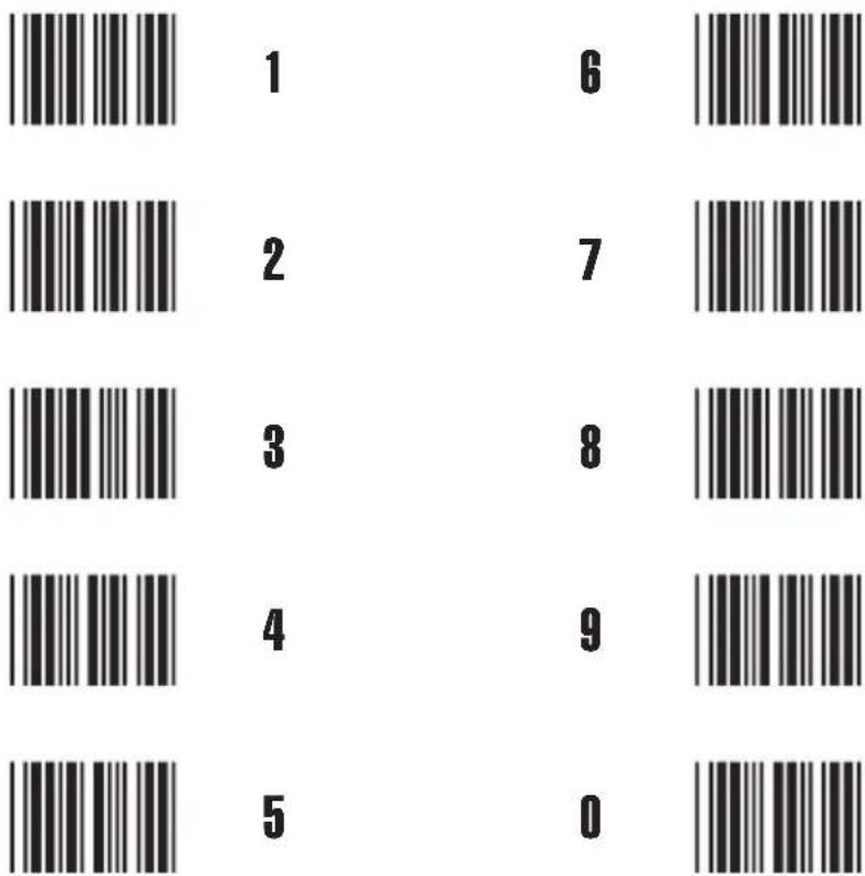
Scan [User Define]
-
Scan 2 numeric barcodes below (Range: 10 to 99)
-
Scan [User Define]
GROUP-2.10
WIRELESS SCANNER SETTINGS
iOS (Apple)
Getting Connected
Please pair with the scanner via [BT mode - HID]. (GROUP 2.6)
Getting Connected without Pincode
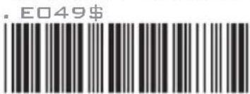
ENABLE SSP
Secure Simple Pairing (SSP), supported by Bluetooth 2.1 or above, allows you to pair with iOS without pincode. Please scan [Enable SSP] above before entering the pairing procedure of [BT mode - HID]. (GROUP 2.6)
Touch Keyboard
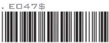
ENABLE iOS HOTKEY
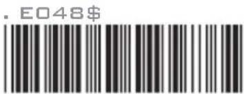
DISABLE iOS HOTKEY
After enabling iOS Hotkey(disabled by default), you may simply double-click the trigger to toggle the iPhone/iPad Touch Keyboard.
Getting Connected
Android
To get connected to Android, please follow the instruction in [BT mode - HID]. (GROUP 2.6)
Touch Keyboard
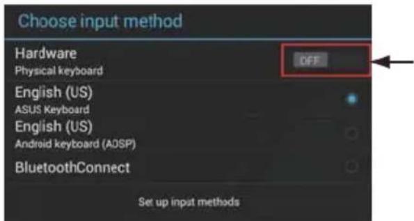
While connected with the scanner, the Touch Keyboard on the Android smartphone or tablet might disappear. To resolve this issue, please change settings on Android device with below steps:
- Enter "Settings"
- Enter "Language & input"
- In Keyboard & input window, tap "Default" to continue.
- Turn off "Hardware - Physical keyboard", and the Touch Keyboard will function properly again.
GROUP-2.11
WIRELESS SCANNER SETTINGS
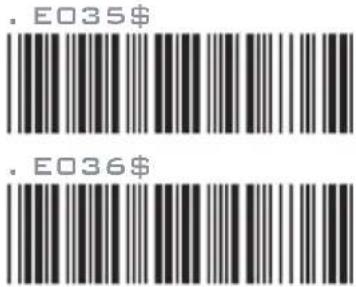
LINK QUALITY
ENABLE
DISABLE
When enabled, Link Quality ensures a more secure data transmission from the scanner to the cradle/host. However the distance of data transmission will decrease.
BATCH MODE
ENABLE
DISABLE
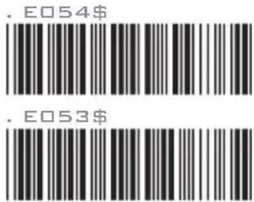
When out of range, the scanner will temporarily keep scanned data in its memory buffer(2K RAM) until the buffer is full. The scanner will send all stored data back to the host after getting in range.
*Note:
- Batch Mode will not function when Memory Mode is enabled, or no connection is made beforehand.
- It is recommended to turn [LINK QUALITY] OFF in order to let Batch Mode function properly.
GROUP-2.12
WIRELESS SCANNER SETTINGS
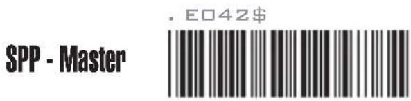
SPP MASTER MODE
First, please generate one configuration barcode for the target SPP slave device in below methods:
- The barcode must be Code 39
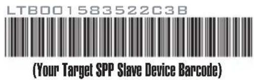
- Barcode data format: LTB + Target MAC address
For example, the target SPP slave device's MAC address is 001583522C3B.
Please encode:
*LTB001583522C3B* in Code39 barcode.
Then, follow below steps to create connection:
STEP 1
STEP 2
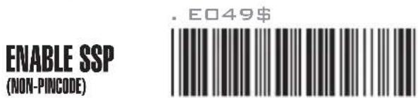
* Note: Please skip this step if the target SPP slave device does not support non-pincode connection.
STEP 3
GROUP-2.13
WIRELESS SCANNER SETTINGS
SET SPP PINCODE
By default, the SPP pincode for the scanner is "1234". You may customize this pincode with below steps:
STEP 1
Set SPP Pincode
. B024\$
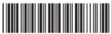
STEP 2
Scan numeric barcodes (see NUMERIC BARCODES below) Up to 8 numbers can be set as SPP pincode.
NUMERIC BARCODES
| 1 | 6 | |
| 2 | 7 | |
| 3 | 8 | |
| 4 | 9 | |
| 5 | 0 |
STEP 3
Set SPP Pincode
. B024\$
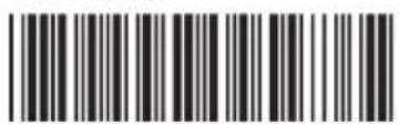
STEP 4
Scan a desired BT mode in Connection Option (GROUP 2.6) to complete the configuration.
GROUP-2.14
WIRELESS SCANNER SETTINGS
SPP REMOTE CONTROL
There are two ways for the scanner to reply to the host whether it is well connected:
Command Response
Host sends: CR,LF,{A,L},CR,LF (8 bytes)
Scanner replies: O,K,CR,LF (4 bytes)
Beeper Response
Host sends: CR,LF,{M,1},CR,LF (8 bytes)
Scanner reacts: a short beep
SHUT DOWN
This configuration barcode will shut down the scanner immediately and reserve the pairing record.
. E255\$
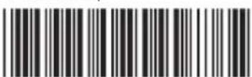
SHUT DOWN
DISCONNECTION
.E031\$

DISCONNECT
(CLEAR PAIRING RECORD)
. E046\$
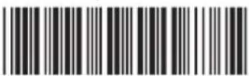
DISCONNECT
(KEEP PAIRING RECORD)
GROUP-2.15
WIRELESS SCANNER SETTINGS
MEMORY MODE
For memory version only
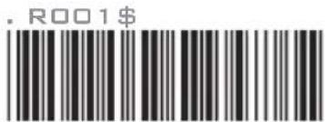
ENABLE MEMORY
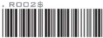
DISABLE MEMORY
Once enabled, the scanner will stop sending data via Bluetooth and start storing data into the internal flash disk (2MB)
Delete Last Record/ Clear All Record
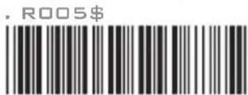
DELETE LAST RECORD
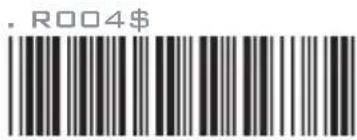
CLEAR ALL RECORD
OUTPUT DATA
For memory version only
OUTPUT DATA
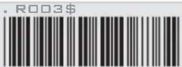
You may output data ONLY when memory is enabled (GROUP 2.15)
Data Output Method
WIRELESS
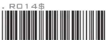
USB-VCP
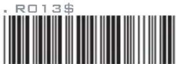
To output stored data via Wireless, please do the following:
- Scan [WIRELESS]
- Scan [OUTPUT DATA]
To output stored data via USB-VCP, please do the following:
- Install VCP driver (available on CD)
- Connect the scanner & host with USB cable
-
Scan [USB-VCP]
-
Save data as *.csv by "Covert to CSV.exe" (available on CD)
GROUP-2.16
WIRELESS SCANNER SETTINGS
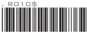
DATA FORMAT
For memory version only
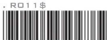
DATA FORMAT
The default Data Format is
| Code | Item Code | Item | ||
| 1 | Item No. | 3 | Time | |
| 2 | Date | 4 | Barcode Data |
Example:
To change Data Format to
- Scan [Data Format]
- Scan [1], [4], [2], [3] from Group 41.
- Scan [Data Format]
FIELD SEPARATOR
Default is comma ( , ). You may replace it with any alphanumeric characters from the full ASCII table in User's Manual (on CD).
Example: To change Field Separator to Semicolon ( ; )
- Scan [Field Separator]
- Scan [ ; ] from the full ASCII table(Group 33-41)
- Scan [Field Separator]
DATE & TIME SETUP

For memory version only
SET DATE
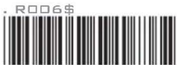
Example: To set Date to 2012-08-01 (Year-Month-Day):
- Scan [Set Date]
- Scan [1], [2], [0], [8], [0], [1] from Group 41.
- Scan [Set Date]
SET TIME
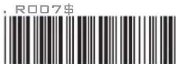
Example: To set Time to 08:10:30 am (Hr:Min:Sec)
- Scan [Set Time]
- Scan [0], [8], [1], [0], [3], [0] from Group 41.
- Scan [Set Time]
* To avoid Time and Date being reset to factory default due to running out of battery, please fully charge the scanner for at least 3 hours before use.
GROUP-2.17
WIRELESS SCANNER SETTINGS
DATE FORMAT
For memory version only
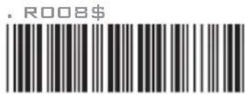
DATE FORMAT
The default Date Format is DD/MM/YYYY (Code = 09), below is full list of available formats and their setup codes:
| Code | Format Code | Format | |
| 01 | DD-MM-YYYY | 09 | DD/MM/YYYY |
| 02 | MM-DD-YYYY | 10 | MM/DD/YYYY |
| 03 | DD-MM-YY | 11 | DD/MM/YY |
| 04 | MM-DD-YY | 12 | MM/DD/YY |
| 05 | YYYY-MM-DD | 13 | YYYY/MM/DD |
| 06 | YY-MM-DD | 14 | YY/MM/DD |
| 07 | DD-MM | 15 | DD/MM |
| 08 | MM-DD | 16 | MM/DD |
Example:
To set Date Format to MM/DD/YY (Code = 12)
- Scan [Date Format]
- Scan [1], [2] from Group 41.
- Scan [Date Format]
TIME FORMAT
For memory version only
TIME FORMAT
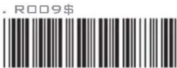
The default Time Format is HH:MM:SS (Code = 01), below are available formats and their setup codes:
Code Format Code Format
01 HH:MM:SS
02
HH:MM
Example:
To set Time Format to HH:MM (Code = 02)
- Scan [Time Format]
- Scan [0], [2] from Group 41.
- Scan [TimeFormat]
GROUP-3
CHECK VERSION, BEEP TONE, TERMINATOR
BEEP TONE MODE
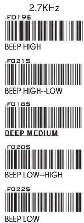
2.1KHz
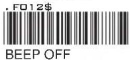
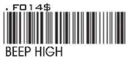
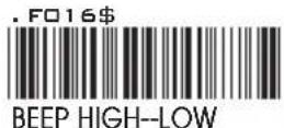
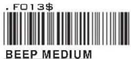
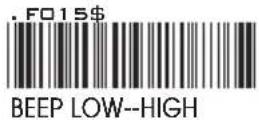
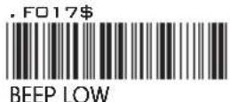
CHECK VERSION
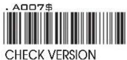
TERMINATOR
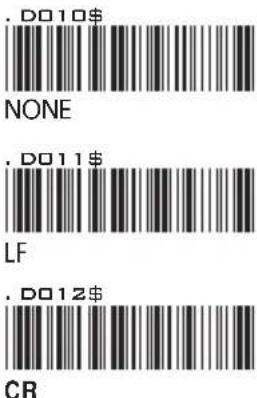
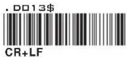
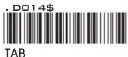
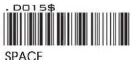
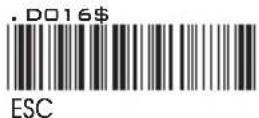
NOTES:
- For the Keyboard Wedge interface the default terminator is CR.
- For the USB interface the default terminator is CR.
- For the RS232 interface the default terminator is CR+LF.
GROUP-4
SEND DATA LENGTH, PREAMBLE & POSTAMBLE.
SEND DATA LENGTH
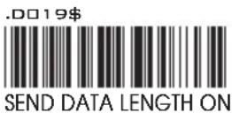
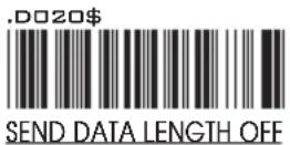
PREAMBLE & POSTAMBLE (PREFIX AND SUFFIX)

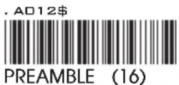
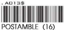
EXAMPLE:
Set PREAMBLE String as “##” POSTAMBLE String as “\\”
SETTING PROCEDURE:
STEP 1 : Scan : CLEAR PRE/ POSTAMBLE.
STEP 2 : Scan : PREAMBLE.
STEP 3 : Scan : “ # ” twice from FULL ASCII Table.
STEP 4 : Scan : PREAMBLE.
STEP 5 : Scan : POSTAMBLE.
STEP 6 : Scan : “ \$ ” twice from FULL ASCII Table.
STEP 7 : Scan : POSTAMBLE.
FORMAT:
{Preamble}{Code ID}{Bar Code}{Postamble}
NOTES:
- A PREAMBLE is a string of up to 16 characters added to the beginning of a scanned barcode.
- A POSTAMBLE is a string of up to 16 characters added to the end of a scanned barcode.
- Default value for both: None.
GROUP-5
ACCURACY ADJUSTMENT
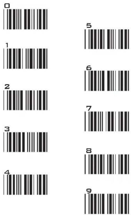
ACCURACY ADJUSTMENT
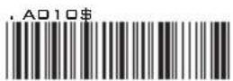
Accuracy Adjustment assures a more reliable decoded output. Enabling the feature and setting a number from 1 to 9 subjects the decoded output a higher standard of accuracy. The higher the number, the greater the accuracy.
SETTING PROCEDURE:
- Scan ACCURACY ADJUSTMENT.
- Scan one digit (1\~9) from barcode menu above.
- Scan ACCURACY ADJUSTMENT.
RESET
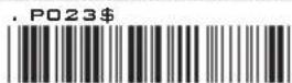
NOTES:
- The scanner will beep three times as reminder that a setting is not yet complete.
- If you make a mistake, forget a step, etc., scan RESET to start again.
GROUP-6
LABEL TYPE POSITIVE / NEGATIVE, ENABLE AND DISABLE CODE ID
LABEL TYPE POSITIVE / NEGATIVE
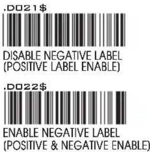
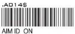
ENABLE CODE ID

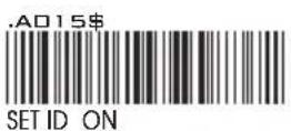
DISABLE CODE ID
NOTES:
- Only ONE code ID will be sent.
- The code ID is located at the position before the bar code data and after the preamble.
EXAMPLE :
1.Preamble 145287,
2.Code ID: enable AIM ID,
3.Bar code symbologies : EAN 13+5
145287
Preamble 145287
]E0
CODE ID AIM ID : ]E0
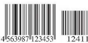
BARCODE / DATA EAN 13 +5
OUTPUT
:145287]E0456398712345312411
GROUP-7
SYMBOLOGIES CODE ID IDENTIFIER, SET ID
SYMBOLOGIES CODE ID IDENTIFIER
| Symbologies | Factory ID | AIM ID (new) | Symbologies | Factory ID | AIM ID (new) |
| EAN 128 | T | ]C1 | MSI | O | ]M0 |
| Code 128 | K | ]C0 | MSI(MOD 10 / CDV & not send CD) | ]M1 | |
| EAN8(+2/+5 OFF) | S | ]E4 | Code 32 | B | ]X0 |
| EAN8(+2 ON) | ]E4 | Codabar | N | ]F0 | |
| EAN8(+5 ON) | ]E4 | Codabar(ABC Codabar) | ]F1 | ||
| UPC-E(+2/+5 OFF) | E | ]E0 | Codabar(CDV & Send CD) | ]F2 | |
| UPC-E(+2 ON) | ]E3 | Codabar(CDV & not send CD) | ]F4 | ||
| UPC-E(+5 ON) | ]E3 | UK Plessey | P | ]P0 | |
| UPC-A(+2/+5 OFF) | A | ]E0 | Matrix 2 of 5 | Y | ]X0 |
| UPC-A(+2 ON) | ]E3 | Full ASCII Code 39(disable CDV) | D | ]A4 | |
| UPC-A(+5 ON) | ]E3 | Full ASCII Code 39(CDV & send CD) | ]A5 | ||
| EAN-13(+2/+5 OFF) | F | ]E0 | Full ASCII Code 39(CDV & not send CD) | ]A7 | |
| EAN-13(+2 ON) | ]E3 | Standard Code 39(disable CDV) | M | ]A0 | |
| EAN-13(+5 ON) | ]E3 | Standard Code 39(CDV & send CD) | ]A1 | ||
| Code 93 | L | ]G0 | Standard Code 39(CDV & not send CD) | ]A3 | |
| Code 11(disable CDV) | J | ]H0 | Interleaved 2 of 5(CDV & send CD) | I | ]I1 |
| Code 11(send one CD) | ]H0 | Interleaved 2 of 5(CDV & not send CD) | ]I3 | ||
| Code 11(send two CD) | ]H1 | Interleaved 2 of 5(disable CDV) | ]I0 | ||
| Code 11(not send CD) | ]H3 | Databar | G | ||
| Telepen(ASCII) | U | ]B0 | Databar Stacked | ||
| Telepen(Numeric) | ]B1 | Databar Stacked Omnidirectional | |||
| IATA 2 of 5 | R | ]R0]e | Databar Truncated | ||
| Industrial 2 of 5 Databar | Limited | ]S0 | C | ||
| China Post Code | H | ]X0 | Databar Expanded | Q | |
| PDF417 | Z | ]E0 | Databar Expanded Stacked |
SET ID - SETTING PROCEDURES
Setting steps:
- Scan the SET ID bar code for a particular symbology.
- Scan one or two alphanumeric characters from the Full ASCII Table.
- Scan the SET ID bar code again.
Example: Define the MSI Code ID = A, Code 93 = G9
MSI :
Step1: Scan MSI Set ID (Group 9).
Step2: "A" from (Group 37).
Step3: Scan MSI Set ID (Group 9).
Code 93:
Step1: Scan Code 93 Set ID (Group8).
Step2: "G" from(Group37), Scan "9" from(Group41).
Step3: Scan Code 93 Set ID (Group8).
NOTES:
- The length of a Code ID is either one or two characters. If one character is set, the Code ID output will be one character. If two characters are set, the Code ID output will be two characters.
- Only one type of Code ID will be sent.
GROUP-8
CODE ID CONFIGURATION: SET ID
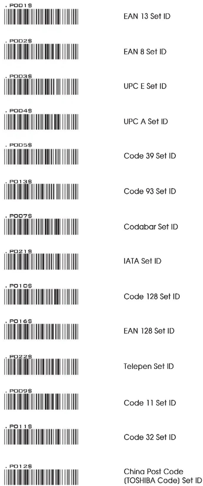
bar
| Set ID | Value ($) | | :--- | :--- | | EAN 13 Set ID | EAN 13 Set ID | | EAN 8 Set ID | EAN 8 Set ID | | UPC E Set ID | UPC E Set ID | | UPC A Set ID | UPC A Set ID | | Code 39 Set ID | Code 39 Set ID | | Code 93 Set ID | Code 93 Set ID | | Codabar Set ID | Codabar Set ID | | IATA Set ID | IATA Set ID | | Code 128 Set ID | Code 128 Set ID | | EAN 128 Set ID | EAN 128 Set ID | | Telepen Set ID | Telepen Set ID | | Code 11 Set ID | Code 11 Set ID | | Code 32 Set ID | Code 32 Set ID | | China Post Code (TOSHIBA Code) Set ID | China Post Code (TOSHIBA Code) Set ID |GROUP-9
CODE ID CONFIGURATION: SET ID
| MSI Code Set ID | P014 |
| UK Plessey Set ID | P015 |
| Matrix 2 of 5 Set ID | P017 |
| Interleaved 2 of 5 Set ID | P006 |
| Industrial 2 of 5 Set ID | P018 |
| Full ASCII Code39 Set ID | P008 |
| GS1 Databar (RSS) Limited Set ID | P019 |
| GS1 Databar (RSS) Expanded Set ID | P020 |
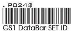
| GS1 Databar (RSS) Set ID | P024 |
| LABEL Code Set ID(Reserved) | P020 |
RESET
- The scanner will beep three times as a reminder that a setting is not yet complete.
- If you make a mistake, forget a step, etc., scan RESET to start again.
GROUP-10
DELAY BETWEEN BLOCKS AND CHARACTERS
INTERBLOCK DELAY
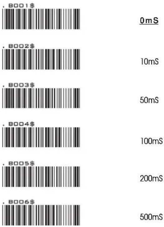
bar
| .B001$ | 0mS | | :--- | :--- | | .B002$ | 10mS | | .B003$ | 50mS | | .B004$ | 100mS | | .B005$ | 200mS | | .B006$ | 500mS |INTERCHARACTER DELAY
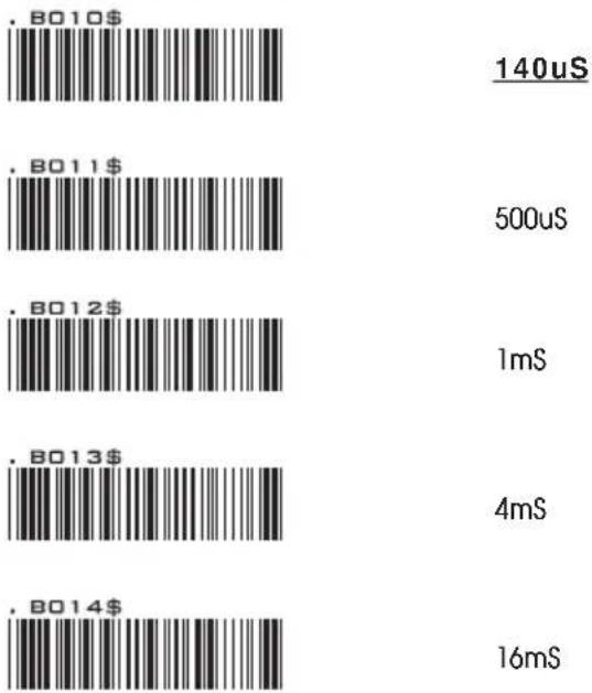
bar
| Price ($) | Duration (uS) | | :--- | :--- | | 140 | | | 500 | | | 1 | | | 4 | | | 16 | |GROUP-11
KEYBOARD LAYOUT/ CAPLOCK MODE/ NUMERIC KEY
KEYBOARD LAYOUT

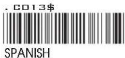
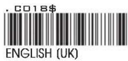
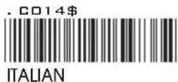
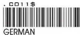
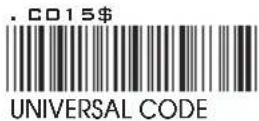
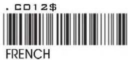
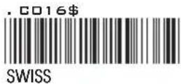
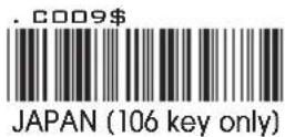
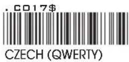
CAPITAL LOCK MODE
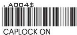
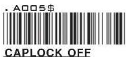
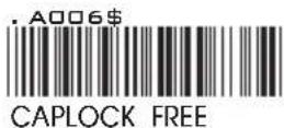
NOTE:
- When barcode scanner is set to Caplock Free mode, no matter keyboard Capslock LED indicator is ON or OFF, output will be always the same as the Original barcode. In other words, what you see is what output is.(CODABAR is the exception)
- If ABCD/ABCD, abcd/abcd, ABCD/T*E, abcd/tn*e are on, they work independently according to their rules.
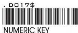
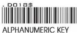
NUMERIC KEY
GROUP-12
RS232: BAUD RATE, DATA BITS & PARITY
BAUD RATE
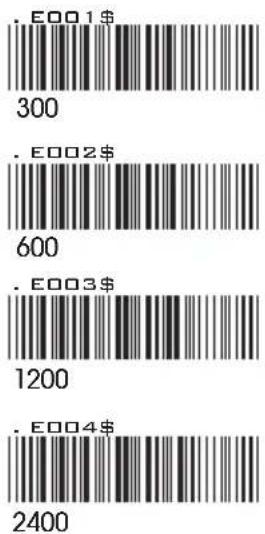
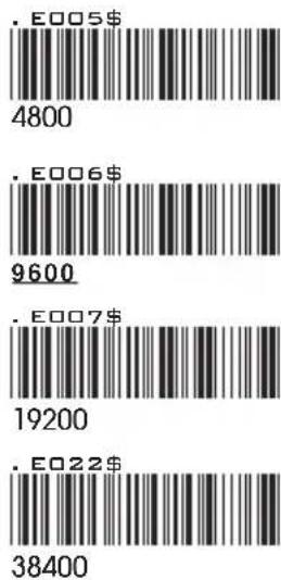
DATA BITS & PARITY
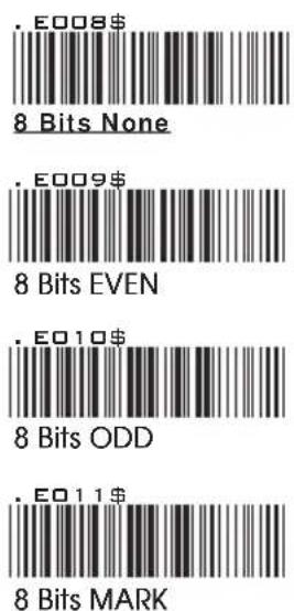
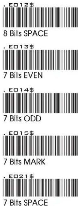
GROUP-13
RS232: STOP BIT, HANDSHAKING, ACK/NAK, FLOW CONTROL, BCC
STOP BITS
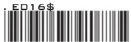
1 STOP BIT

2 STOP BITS
HANDSHAKING
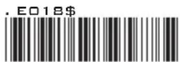
NONE
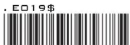
RTS enable at Power on
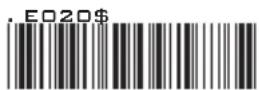
RTS enable with Communication
ACK / NAK
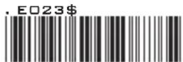
ON
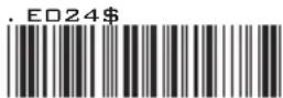
OFF
FLOW CONTROL: TIME OUT
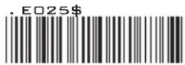
1 Sec
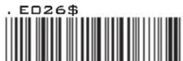
3 Sec
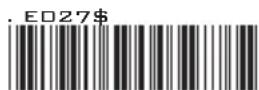
10 Sec
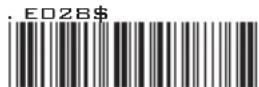
Unlimited
BCC
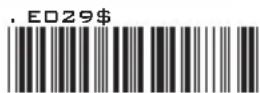
RS232 BCC Char On
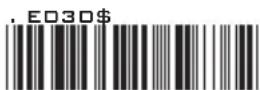
RS232 BCC Char Off
GROUP-14
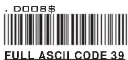
WAND EMULATION PARAMETER SETTING
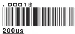
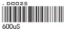
LEVEL DURATION OF
MINI WIDTH
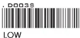
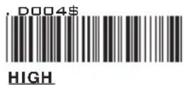
POLARITY OF
IDLE CONDITION

OUTPUT OF WAND EMULATION
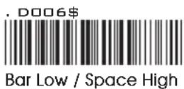
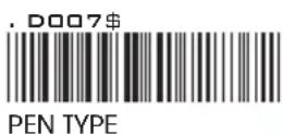
WAVE FORM
GROUP-15
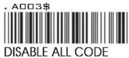
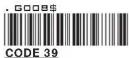
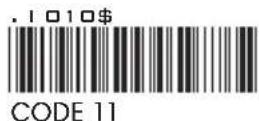
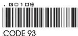
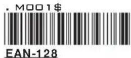
ENABLE/ DISABLE SYMBOLOGIES
ENABLE
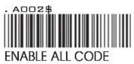
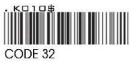


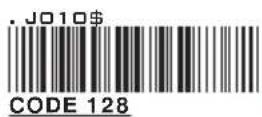
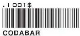
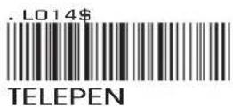
DISABLE
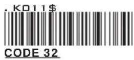
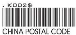


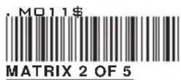
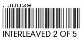
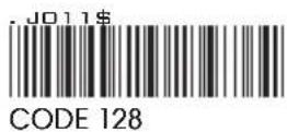
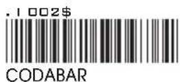
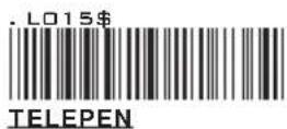
GROUP-16
ENABLE/ DISABLE SYMBOLOGIES
ENABLE
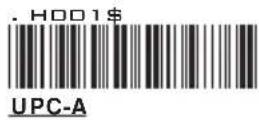
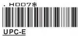
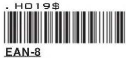
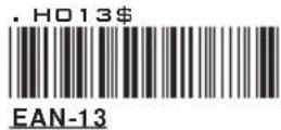
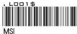
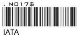
DISABLE
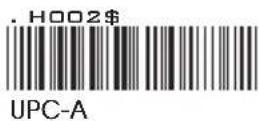
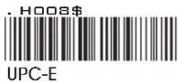
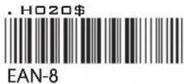
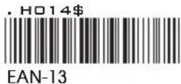
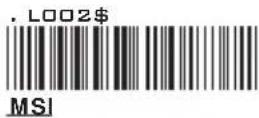
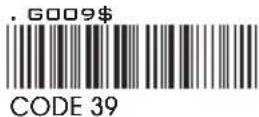
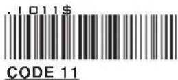
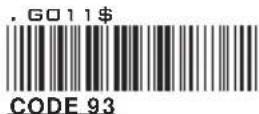
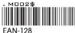
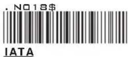
GROUP-17
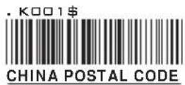
ENABLE/DISABLE SYMBOLOGIES, CHINA POSTAL CODE
ENABLE
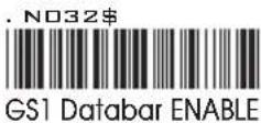
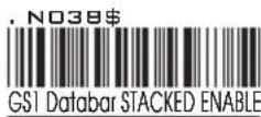
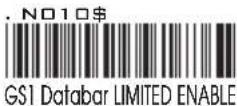
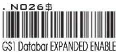
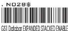
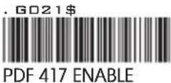
DISABLE
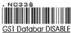
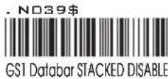
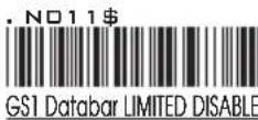
CHINA POSTAL CODE [ TOSHIBA CODE ]
![Unitech MS146-IUCB0M-SG - CHINA POSTAL CODE [ TOSHIBA CODE ] - 1](/content/2026/05/1048873/images/bf06faefdb68be67030d1d25d888a6ec28bd2795d95bb10fb44a8111e4d800ff.jpg)
![Unitech MS146-IUCB0M-SG - CHINA POSTAL CODE [ TOSHIBA CODE ] - 2](/content/2026/05/1048873/images/5d531a15de74587741321dbea67bd2ac8d0fc50bfbe0ceed209c1ef2f9f169dc.jpg)
![Unitech MS146-IUCB0M-SG - CHINA POSTAL CODE [ TOSHIBA CODE ] - 3](/content/2026/05/1048873/images/0d7430970aca28a063df457b103db9d56d0395ebf5674540aa4fb01101a0b599.jpg)
![Unitech MS146-IUCB0M-SG - CHINA POSTAL CODE [ TOSHIBA CODE ] - 4](/content/2026/05/1048873/images/9c6ea5681e27ab230b67517bd09ac4a1012b5c46a6ba49601651a79d4c2f154a.jpg)
![Unitech MS146-IUCB0M-SG - CHINA POSTAL CODE [ TOSHIBA CODE ] - 5](/content/2026/05/1048873/images/1023ddd31e6d99a4eb9256420e3cbaf453188834ea117c81470d3979368da98a.jpg)
![Unitech MS146-IUCB0M-SG - CHINA POSTAL CODE [ TOSHIBA CODE ] - 6](/content/2026/05/1048873/images/408626904f49310b56617e7a7921c2d1c136f8db01d0cf5498d7481c81d5bcc3.jpg)
![Unitech MS146-IUCB0M-SG - CHINA POSTAL CODE [ TOSHIBA CODE ] - 7](/content/2026/05/1048873/images/46628144698d19f64021c9395eb50e8f9209112c1a42f0527eca4b61f766701c.jpg)
APPENDIX
FULL ASCII (Code 39) NUMERIC TABLE
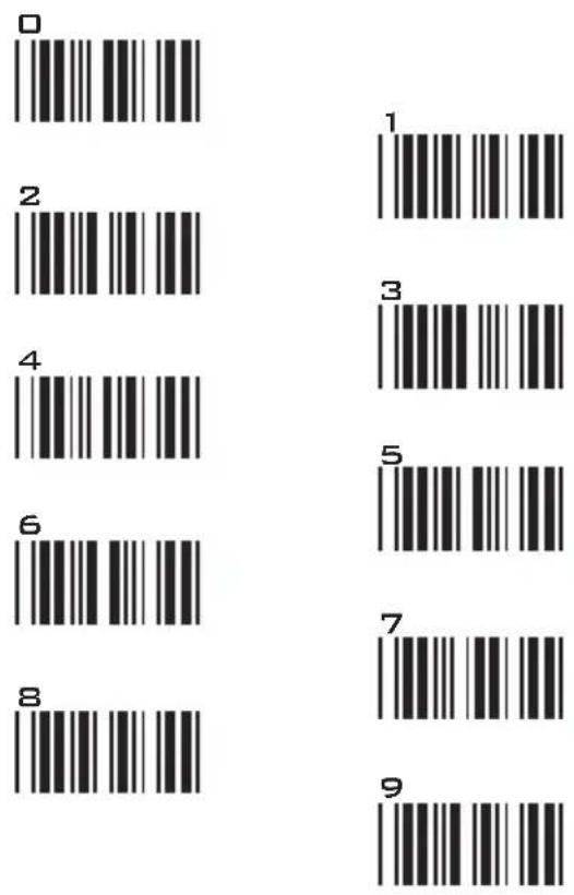
SETTING PROCEDURE
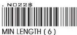
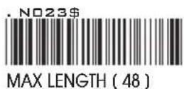
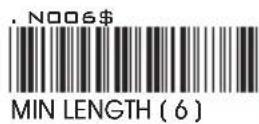
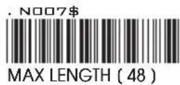
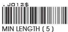
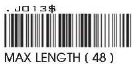
MIN / MAX LENGTH
STEP 1 - Scan: MIN LENGTH/ MAX LENGTH
STEP 2 - Scan: Two digits from Appendix.
STEP 3 - Scan: MIN LENGTH/ MAX LENGTH
Please note that when Min Length and / or Max Length are enabled, the scanner will only read bar codes that fall into those length parameters. Bar codes shorter or longer than specified will not be read. The default lengths for these are indicated in parentheses under the Min and Max bar codes for each symbology.
NOTES:
- The scanner will beep three times as a reminder that a setting is not yet complete.
- If you make a mistake, forget a step, etc., Scan RESET to start again.


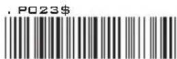
GROUP-18
SYMBOLOGIES: MSI CODE, UK PLESSEY CODE
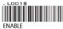
MSI
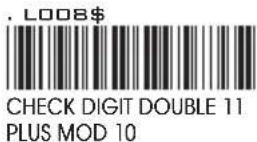
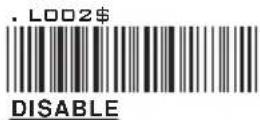
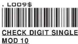

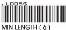

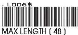
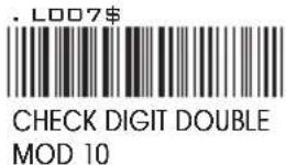
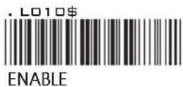
UK PLESSEY CODE
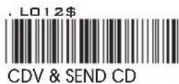
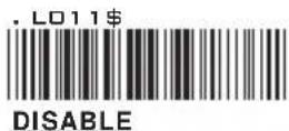

APPENDIX
FULL ASCII (Code 39) NUMERIC TABLE
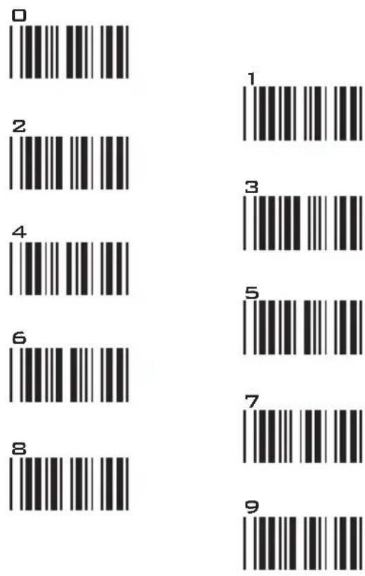
SETTING PROCEDURE
MIN / MAX LENGTH
STEP 1 - Scan: MIN LENGTH/ MAX LENGTH
STEP 2 - Scan: Two digits from Appendix.
STEP 3 - Scan: MIN LENGTH/ MAX LENGTH
Please note that when Min Length and / or Max Length are enabled, the scanner will only read bar codes that fall into those length parameters. Bar codes shorter or longer than specified will not be read. The default lengths for these are indicated in parentheses under the Min and Max bar codes for each symbology.
NOTES:
- The scanner will beep three times as a reminder that a setting is not yet complete.
- If you make a mistake, forget a step, etc., Scan RESET to start again.


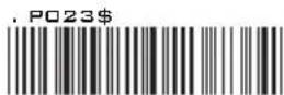
GROUP-19
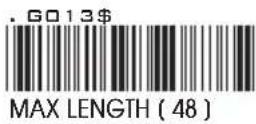
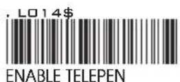
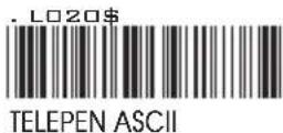
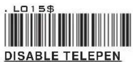
SYMBOLOGIES: CODE 93, TELEPEN, IATA
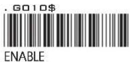
CODE 93
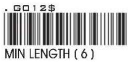
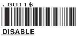
TELEPEN
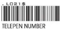
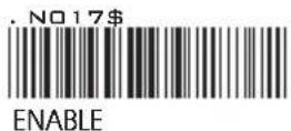
IATA
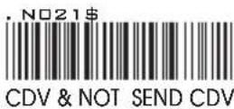
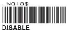
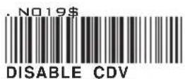

APPENDIX
FULL ASCII (Code 39) NUMERIC TABLE
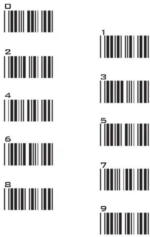
SETTING PROCEDURE
MIN / MAX LENGTH
STEP 1 - Scan: MIN LENGTH/ MAX LENGTH
STEP 2 - Scan: Two digits from Appendix.
STEP 3 - Scan: MIN LENGTH/ MAX LENGTH
Please note that when Min Length and / or Max Length are enabled, the scanner will only read bar codes that fall into those length parameters. Bar codes shorter or longer than specified will not be read. The default lengths for these are indicated in parentheses under the Min and Max bar codes for each symbology.
NOTES:
- The scanner will beep three times as a reminder that a setting is not yet complete.
- If you make a mistake, forget a step, etc., Scan RESET to start again.


GROUP-20
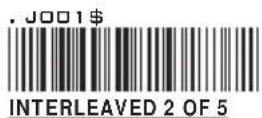
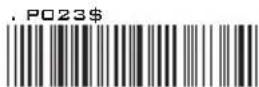
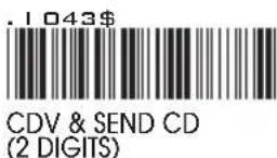
SYMBOLOGIES: INTERLEAVED 2 OF 5, CODE 11
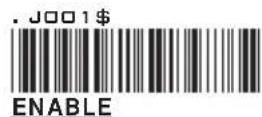
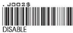
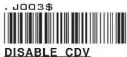


INTERLEAVED 2 OF 5
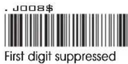
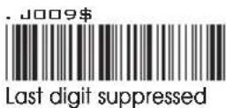
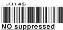
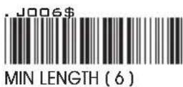
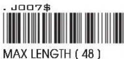
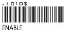
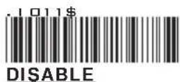

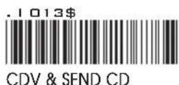
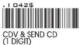
CODE 11

APPENDIX
FULL ASCII (Code 39) NUMERIC TABLE
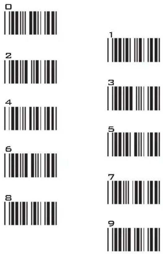
SETTING PROCEDURE
MIN / MAX LENGTH
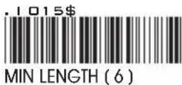
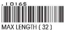
STEP 1 - Scan: MIN LENGTH/ MAX LENGTH
STEP 2 - Scan: Two digits from Appendix.
STEP 3 - Scan: MIN LENGTH/ MAX LENGTH
Please note that when Min Length and / or Max Length are enabled, the scanner will only read bar codes that fall into those length parameters. Bar codes shorter or longer than specified will not be read. The default lengths for these are indicated in parentheses under the Min and Max bar codes for each symbology.
NOTES:
- The scanner will beep three times as a reminder that a setting is not yet complete.
- If you make a mistake, forget a step, etc., Scan RESET to start again.


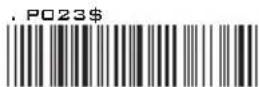
GROUP-21
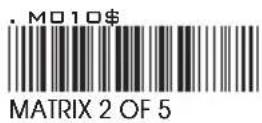
SYMBOLOGIES: INDUSTRIAL 2 OF 5, MATRIX 2 OF 5
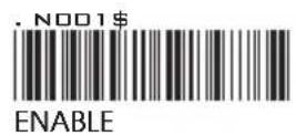
INDUSTRIAL 2 OF 5

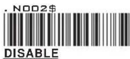
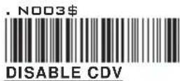

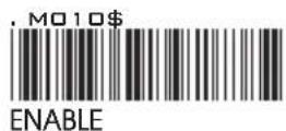
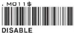
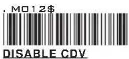

MATRIX 2 OF 5

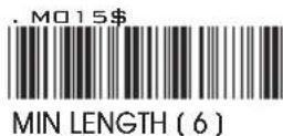
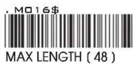
APPENDIX
FULL ASCII (Code 39) NUMERIC TABLE
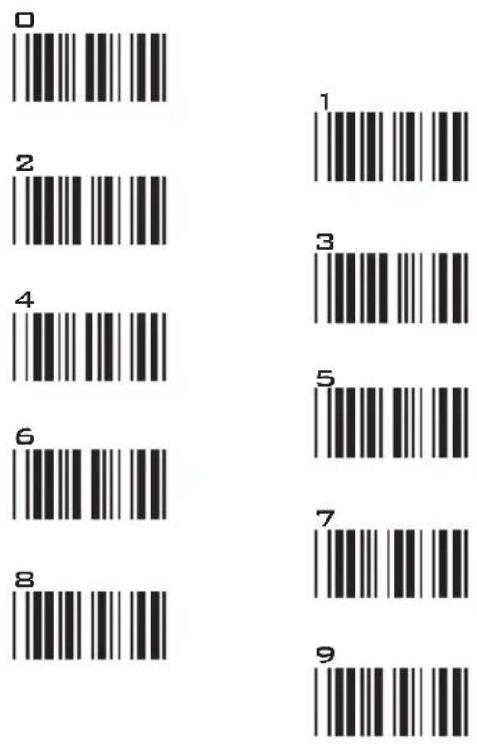
SETTING PROCEDURE
MIN / MAX LENGTH
STEP 1 - Scan: MIN LENGTH/ MAX LENGTH
STEP 2 - Scan: Two digits from Appendix.
STEP 3 - Scan: MIN LENGTH/ MAX LENGTH
Please note that when Min Length and / or Max Length are enabled, the scanner will only read bar codes that fall into those length parameters. Bar codes shorter or longer than specified will not be read. The default lengths for these are indicated in parentheses under the Min and Max bar codes for each symbology.
NOTES:
- The scanner will beep three times as a reminder that a setting is not yet complete.
- If you make a mistake, forget a step, etc., Scan RESET to start again.


GROUP-22
SYMBOLOGIES: CODABAR
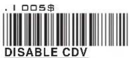

CODABAR

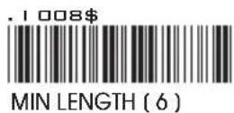
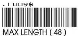
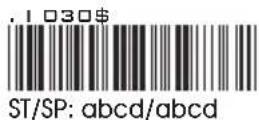
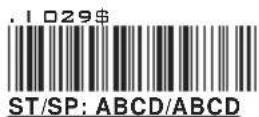
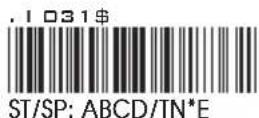
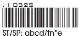
START / STOP
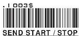
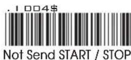
Example of ST (Start) / SP (Stop) 123456 Not Transmit ST/SP
| A123456B | ST/SP: | ABCD/ABCD |
| a123456b | ST/SP: | abcd/abcd |
| A123456N | ST/SP: | ABCD/TN*E |
| a123456n | ST/SP: | abcd/tn*e |
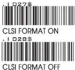
CLSI FORMAT
CLSI- Enable library space insertion. If you enable the CLSI format, this option inserts spaces in position 2, 7, 13 of the data string for use in library systems.
APPENDIX
FULL ASCII (Code 39) NUMERIC TABLE
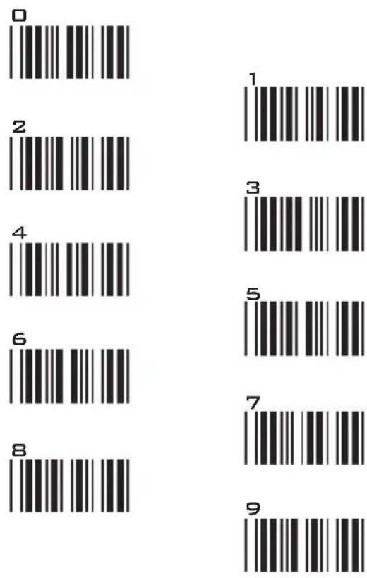
SETTING PROCEDURE
MIN / MAX LENGTH
STEP 1 - Scan: MIN LENGTH/ MAX LENGTH
STEP 2 - Scan: Two digits from Appendix.
STEP 3 - Scan: MIN LENGTH/ MAX LENGTH
Please note that when Min Length and / or Max Length are enabled, the scanner will only read bar codes that fall into those length parameters. Bar codes shorter or longer than specified will not be read. The default lengths for these are indicated in parentheses under the Min and Max bar codes for each symbology.
NOTES:
- The scanner will beep three times as a reminder that a setting is not yet complete.
- If you make a mistake, forget a step, etc., Scan RESET to start again.


GROUP-23
SYMBOLOGIES: ABC-CODABAR, CX-CODABAR
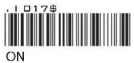
ABC- CODABAR
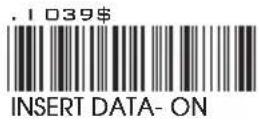
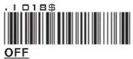
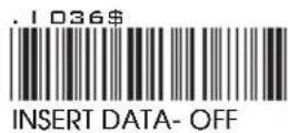
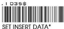
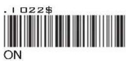
* The data can be any alphanumerics of FULL ASCII Table (GROUP 33-41)
REMARK:
ABC-CODABAR (American Blood Commission). The ABC Code is an acronym for American Blood Commission. This bar code is a variant of the CODABAR Code developed for the use in the blood bank. This Code consists of two bar codes which are decoded in one read cycle. The code is concatenated when the stop character of the first bar code and the start character of the second bar code is a “D”, these two “D” are not transmitted.
CX CODE- CODABAR
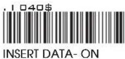
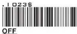
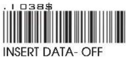
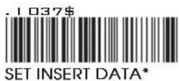
* The data can be any alphanumerics of FULL ASCII Table (GROUP 33-41)
REMARK:
The CX-Code consists of two bar codes which are decoded in one read cycle, the code is concatenated when the stop character of the first bar code is a C, and the start character of the second bar code is a B. The B and C characters are not transmitted.
GROUP-24
SYMBOLOGIES: CODABAR COUPLING, ADJACENT REQUIRED
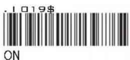
CODABAR COUPLING
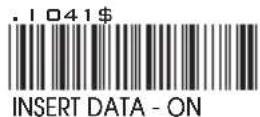
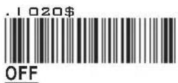
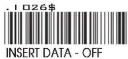
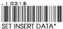
ABC-Codabar and CX-Codabar have certain rules regarding the Stop Character of first bar code and the stop character of second bar code while in conjunction, while Codabar-Coupling is enabled, the data from any two Codabar bar codes can be coupled into one set of data without any limitations between the Stop character of first bar code and the Start character of second bar code. The Start and Stop characters associated with each bar code will be sent.
* The data can be any alphanumerics of FULL ASCII Table (GROUP 33-41)
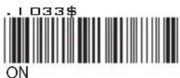
ADJACENT REQUIRED
If CODABAR ADJACENT is enabled, the scanner will only read two adjacent Codabar bar codes; a single bar code will not be read.
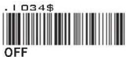
NOTES:
- Both ABC-Codabar and CX-Codabar can be enabled together, except when Codabar-Coupling is also enabled.
- If ABC-Codabar, CX-Codabar, and Codabar-Coupling are all enabled at the same time, the scanner will read only Codabar-Coupling, that is, ABC-Codabar, CX-Codabar will be considered coupling formats.
SETTING PROCEDURE - SET INSERT DATA
Step 1- Scan SET INSERT DATA.
Step 2- Scan any combination of alphanumeric characters from FULL ASCII Table.
Step 3- Scan SET INSERT DATA.
RESET
NOTES:
- The scanner will beep three times as a reminder that a setting is not yet complete.
- If you make a mistake, forget a step, etc., Scan RESET to start again.
GROUP-25
SYMBOLOGIES: STANDARD & FULL ASCII CODE 39, CODE 32
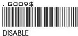
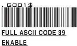
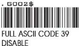
STANDARD CODE 39 & FULL ASCII 39
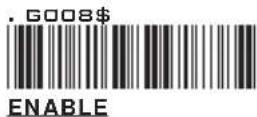
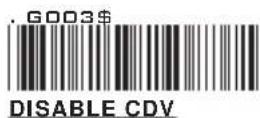


NOTE:
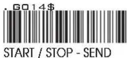
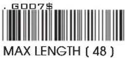
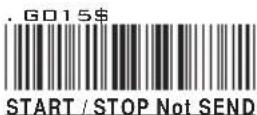
The default for Code 39 is Standard Code 39. If Full ASCII Code 39 is enabled, Standard Code 39 will be automatically disabled.
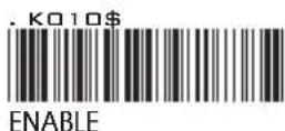
CODE 32
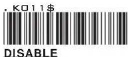
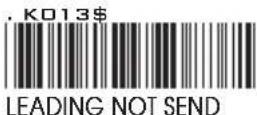
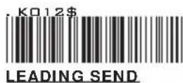
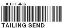
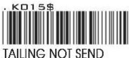
APPENDIX
FULL ASCII (Code 39) NUMERIC TABLE
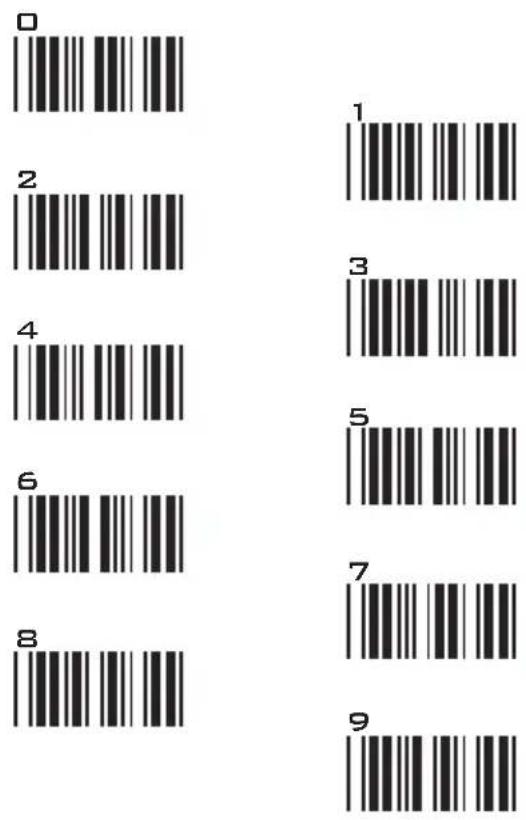
SETTING PROCEDURE
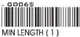
MIN / MAX LENGTH
STEP 1 - Scan: MIN LENGTH/ MAX LENGTH
STEP 2 - Scan: Two digits from Appendix.
STEP 3 - Scan: MIN LENGTH/ MAX LENGTH
Please note that when Min Length and / or Max Length are enabled, the scanner will only read bar codes that fall into those length parameters. Bar codes shorter or longer than specified will not be read. The default lengths for these are indicated in parentheses under the Min and Max bar codes for each symbology.
NOTES:
- The scanner will beep three times as a reminder that a setting is not yet complete.
- If you make a mistake, forget a step, etc., Scan RESET to start again.


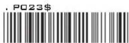
GROUP-26
SYMBOLOGIES FORMATTING: UPC-E
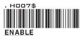
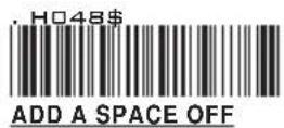
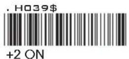
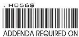
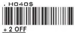
UPC-E
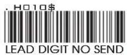
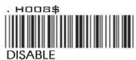
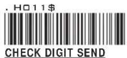
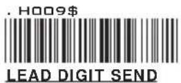
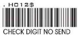
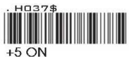
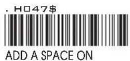
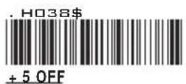
ADD ON SUPPLEMENT
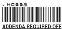
NOTE:
If ADDENDA REQUIRED is set to ON, the scanner will only read an UPC-E bar code that has an addenda. At the same time please also scan +5 ON or +2 ON so the scanner will output a 5-digit or 2-digit addendum.
GROUP-27
SYMBOLOGIES: UPC-E SYSTEM NUMBER
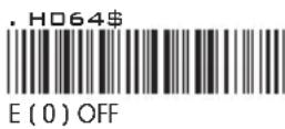
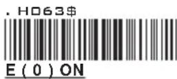
UPC-EO
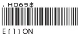
UPC-E1
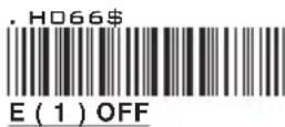
NOTE:
Most UPC bar codes lead with 0 number systems, for these bar codes use UPC E(0) selection. For the bar codes that lead with the 1 number, use UPC E(1) selection.
- If UPC-E EXPAND TO UPC A FORMAT is enabled, the output of UPC-A will be 12 digits.
- The default output of UPC-A is 12 digits, if UPC-A EXPAND TO EAN13 is enabled, a zero will be added to in front of the bar code.
GROUP-28
SYMBOLOGIES FORMATTING: UPC-A
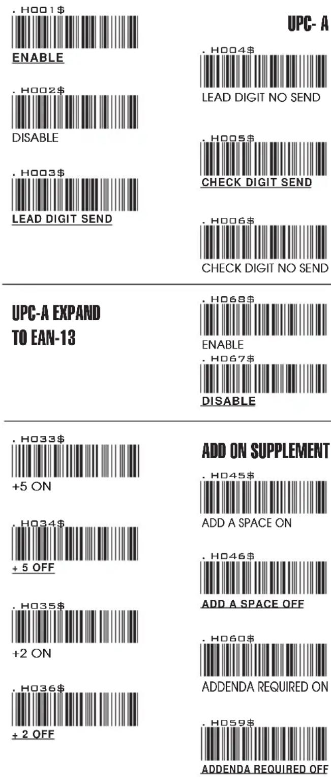
NOTE:
If ADDENDA REQUIRED is set to ON, the scanner will only read an UPC-E bar code that has an addenda. At the same time please also scan +5 ON or +2 ON so the scanner will output a 5-digit or 2-digit addendum.
GROUP-29
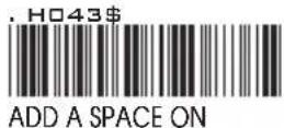
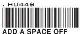
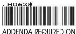
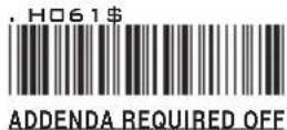
SYMBOLOGIES FORMATTING: EAN 8
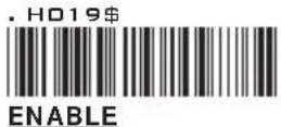
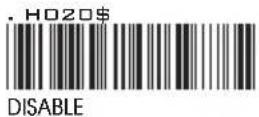
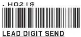
EAN-8
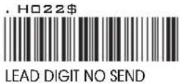
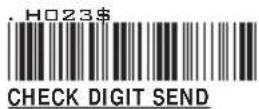
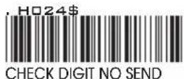
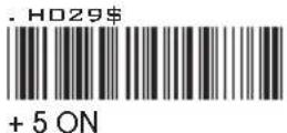
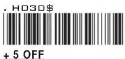
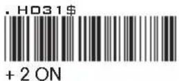
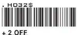
ADD ON SUPPLEMENT
NOTE:
If ADDENDA REQUIRED is set to ON, the scanner will only read an UPC-E bar code that has an addenda. At the same time please also scan +5 ON or +2 ON so the scanner will output a 5-digit or 2-digit addendum.
GROUP-30
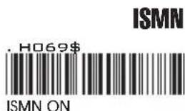
SYMBOLOGIES FORMATTING: EAN13, ISBN, ISSN, ISMN
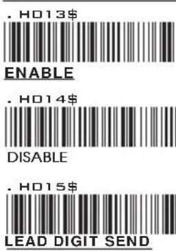
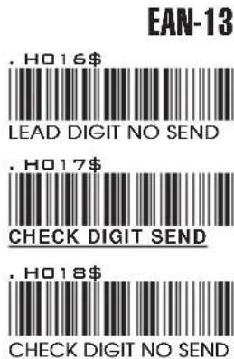
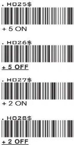
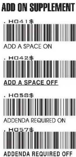
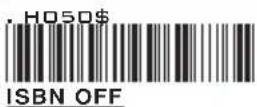
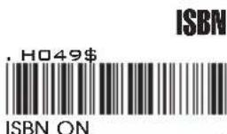
NOTES:
- If ADDENDA REQUIRED is set to ON, the scanner will only read an EAN-13 bar code that has an addenda.
- Either ISSN or ISBN will be considered as an extension of EAN-13. If ISSN or ISBN needs to be read, EAN-13 must be enabled. If ISSN and ISBN need to be read with addenda, EAN-13 must be enabled with ADDENDA REQUIRED set to ON, and +2 ON or +5 ON must be enabled as well.
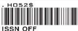

NOTE:
Both ISSN and ISBN are the extension codes of EAN-13. If scanner is required to read either ISSN or ISBN, EAN-13 must be enabled. Otherwise the scanner will not be able to read ISSN or ISBN.
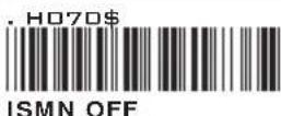
GROUP-31
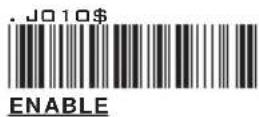
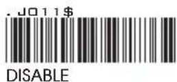
SYMBOLOGIES: EAN/UCC-128, CODE 128
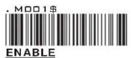
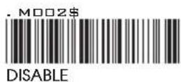
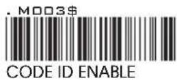
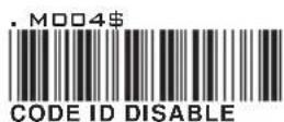
EAN/ UCC-128
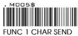
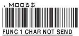
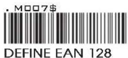
NOTES: DEFINE EAN 128
The first FNC1 character is translated to ]c1, and the second FNC1 character is translated to an ASCII
String format:
| |C1 | DATA CHARACTERS | DATA CHARACTERS |
Setting Procedure:
1: Scan DEFINE EAN128.
2: Scan ASCII Code ( Group 41 )
3: Scan DEFINE EAN128.
CODE 128
PDF417
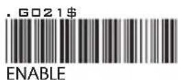
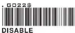
GROUP-32
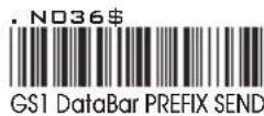
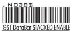
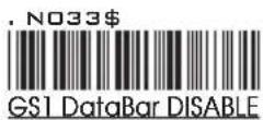
GS1 DataBar, LIMITED, EXPANDED
GS1 DataBar (RSS) - OMNI & STACKED
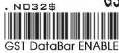
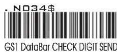
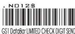
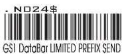
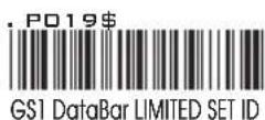
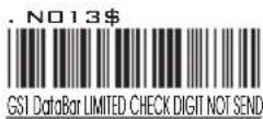
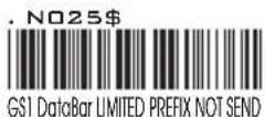
GS1 DataBar (RSS) - LIMITED
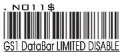
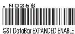
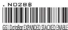
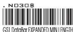
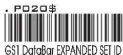
GS1 DataBar (RSS) - EXPANDED
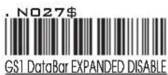
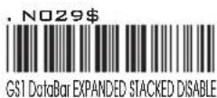
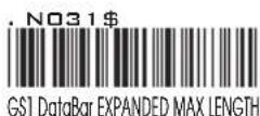
GROUP-33
FULL ASCII TABLE ( CODE 39 ) CONTROL CODES
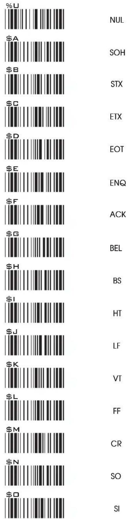
NUL
SOH
STX
ETX
EOT
ENQ
ACK
BEL
BS
HT
LF
VT
FF
CR
SO
SI
GROUP-34
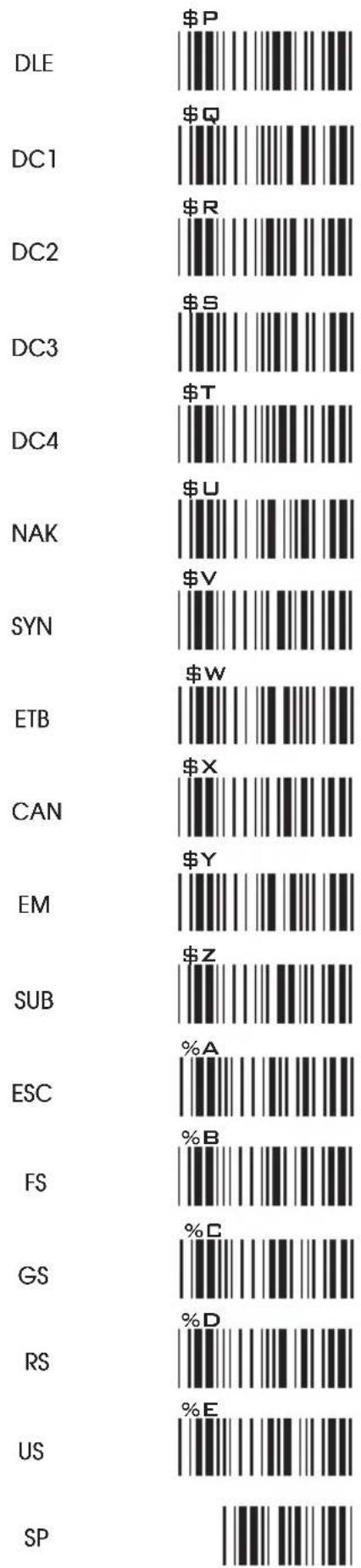
FULL ASCII TABLE ( CODE 39 ) CONTROL CODES
bar
| Category | Value ($) | |---|---| | DLE | $P | | DC1 | $Q | | DC2 | $R | | DC3 | $S | | DC4 | $T | | NAK | $U | | SYN | $V | | ETB | $W | | CAN | $X | | EM | $Y | | SUB | $Z | | ESC | %A | | FS | %B | | GS | %C | | RS | %D | | US | %E | | SP | |GROUP-35
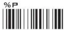
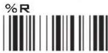
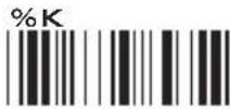
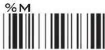
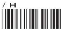
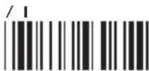
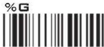
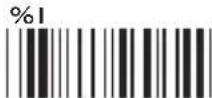
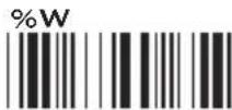
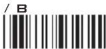
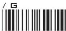
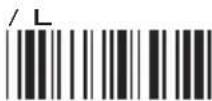
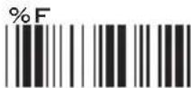
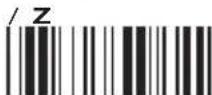
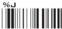
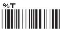
FULL ASCII TABLE ( CODE 39 ) SYMBOLS
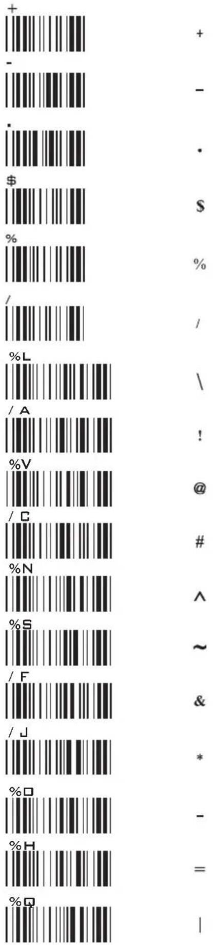
GROUP-36
FULL ASCII TABLE ( CODE 39 )
SYMBOLS
![{ %P } %R [ %K ] %M ( /H ) / I < %G > %I , %W " /B , / G , / L ; %F : /Z ? %J DEL %T](/content/2026/05/1048873/images/518c15175044ac2d7b0d2136972e0af723dfe22583039c7ac1a4ee00d928a235.jpg)
GROUP-37
FULL ASCII TABLE ( CODE 39 ) UPPER CASE ALPHABETS
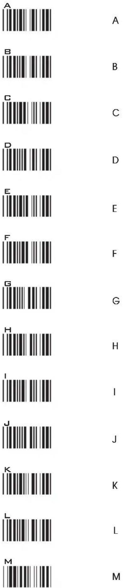
GROUP-38
FULL ASCII TABLE ( CODE 39 ) UPPER CASE ALPHABETS
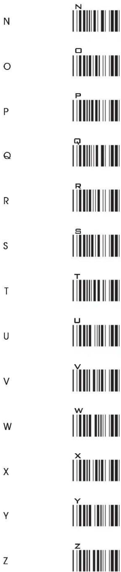
GROUP-39
FULL ASCII TABLE ( CODE 39 ) LOWER CASE ALPHABETS
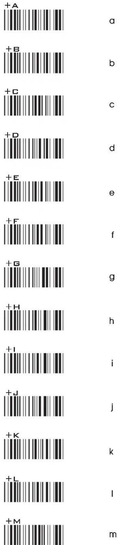
GROUP-40
FULL ASCII TABLE ( CODE 39 ) LOWER CASE ALPHABETS
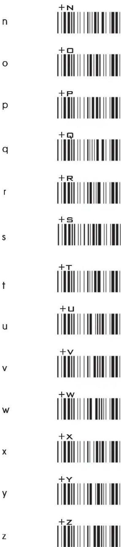
GROUP-41
FULL ASCII TABLE ( CODE 39 ) NUMBERS
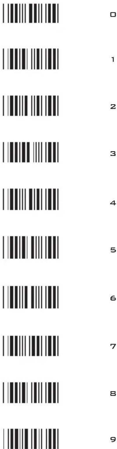
GROUP-42
FULL ASCII TABLE ( CODE 39 )
FUNCTION KEYS
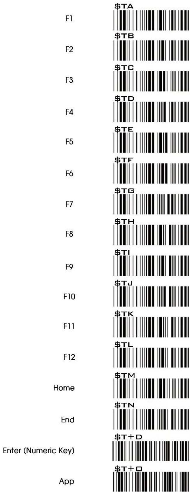
bar
| Category | Value ($) | |---|---| | F1 | $TA | | F2 | $TB | | F3 | $TC | | F4 | $TD | | F5 | $TE | | F6 | $TF | | F7 | $TG | | F8 | $TH | | F9 | $TI | | F10 | $TJ | | F11 | $TK | | F12 | $TL | | Home | $TM | | End | $TN | | Enter (Numeric Key) | $T+D | | App | $T+D |GROUP-43
FULL ASCII TABLE ( CODE 39 ) NAVIGATION KEYS
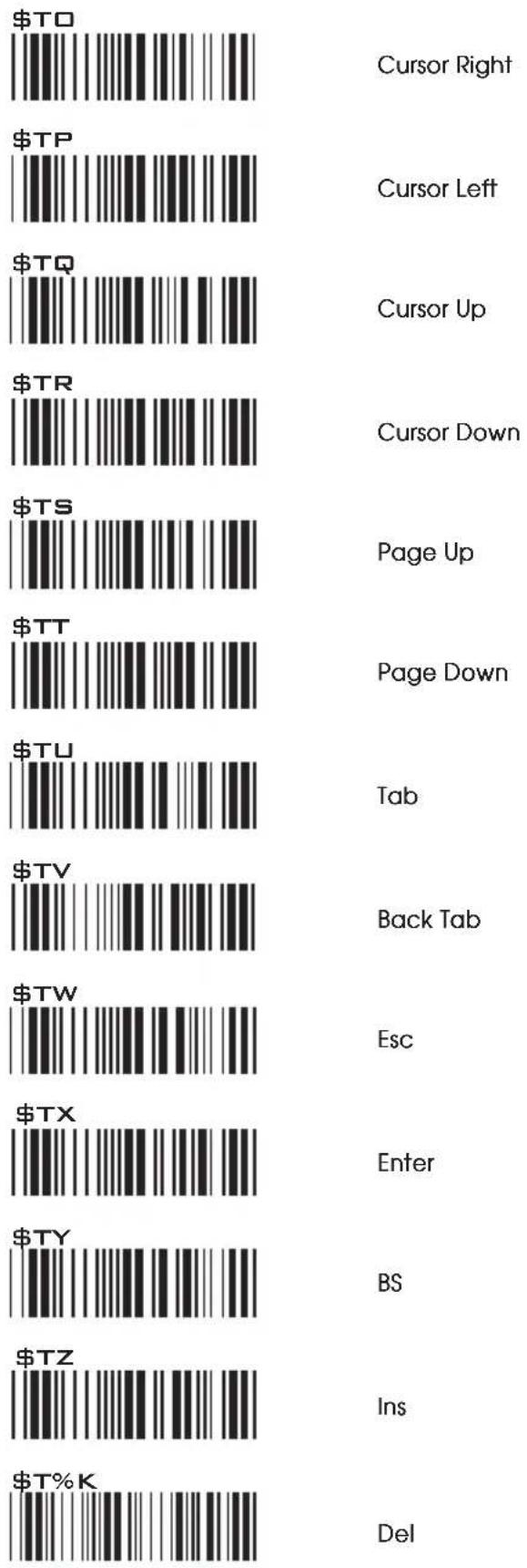
Cursor Right
Cursor Left
Cursor Up
Cursor Down
Page Up
Page Down
Tab
Back Tab
Esc
Enter
BS
Ins
Del
GROUP-44
FULL ASCII TABLE ( CODE 39 ) MODIFIER KEYS
\$T%L
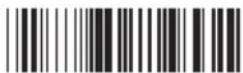
Alt (Left) make*1
\$T+E

Alt (Right) make
\$T%N

Shift (Left) make *2
\$T+1
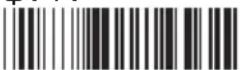
Shift (Right) make
\$T+K

Win (Left) make
\$T+M
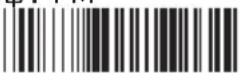
Win (Right) make
\$T%W
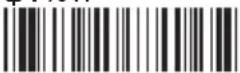
Ctrl (Left) make *3
\$T+G

Ctrl (Right) make
\$T%M

Alt (Left) break
\$T+F
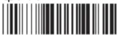
Alt (Right) break
\$T%□

Shift (Left) break
\$T+J

Shift (Right) break
\$T+L

Win (Left) break
\$T+N
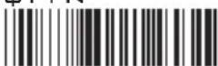
Win (Right) break
\$T+A
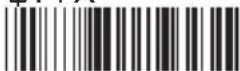
Ctrl (Left) break
\$T+H
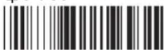
Ctrl (Right) break
For UK Keyboard Special Character
\$T+B
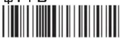

\$T+C
£
Note:
*1: When "Alt(Left)Make" is programmed, please scan "Alt(Left)Break" to resume barcode setting.
*2: When "Shift(Left)Make" is programmed, please scan "Shift(Left)Break" to resume barcode setting.
*3: When "Ctrl(Left)Make" is programmed, please scan "Ctrl(Left)Break" to resume barcode setting.
Our Barcode Scanners are simple to install and use.
Most operational issues can be attributed to:

INCORRECT INTERFACE CONNECTION INCORRECT CONFIGURATION SETUP POOR BARCODE QUALITY
GENERAL PROCEDURES
- First, make sure the scanner is firmly connected to the host computer, when attached correctly, the scanner will emit one long beep. When the trigger is pressed, LED will flash.
- Once the power is on, try scanning some sample bar codes from this user's guide. The scanner should beep and the LED should flash to indicate a good read in the default configuration. If reading the bar code does not result in a good read, there may have been a problem with the scanning technique or the interface configuration setting. Reset the scanner to default.
- If the scanner indicates a good read, but there is no output of data to the monitor, please check the cabling connection.
KEYBOARD INTERFACES PROBLEMS
In general, the Keyboard Wedge interface is trouble free, but there is still something to check in the event of a problem:
Do you have the correct cable?
Most computers use an XT/AT-compatible keyboard. Be sure you have the proper cable for your computer.
Does the keyboard work?
Since the keyed-in data from keyboard must pass through the decoder, the cabling connections are correct if the keyboard is functioning.
Can your computer accept the data fast enough?
Your computer's BIOS has a feature related to keyboard typing speed. Try to set the Intercharacter Delay feature to stimulate the keystroke entry speed.
Does keyboard port supply enough power?
Most notebook computers do not supply enough power to the scanner. The symptom of insufficient power is a lower “good read” rate (since there is not enough power to properly support the scanning operation).
Is the proper symbology enabled?
Each bar code symbology can be individually enabled or disabled. It is suggested that you enable only those that you will be scanning, thereby eliminating the possibility of mis reads from the scanning of other symbologies.
Does the selected bar code symbology configuration match the bar code(s) being read?
Scanned data from each bar code symbology can be restricted to eliminate the scanning of unused symbologies.
The restrictions are individually set for each symbology.
POOR BAR CODE QUALITY
The third problem area has nothing to do with the scanner, but rather the printed quality of the bar code and/or the scanning technique employed.
TOLERANCE OF BAR CODE
A bar code may have a tolerance. Normally, the tolerances are caused by bar code font software or a printer. Software with a proven reputation should be chosen to generate bar codes. If the printed bar codes are distorted, the scanner might not recognize them.
It is very difficult to get a good read from a poor quality bar code unless it is scanned many times. As the quality of the symbology drops, the chances for undetected error increase. A bar code Check Digit Verification (CDV) should be used to check the quality of the suspect bar codes.
LABELS (PAPER & COLOR & PRINTER)
The light source of a bar code scanner is generally red, so there are some restrictions for the printing of labels. Care should be taken when choosing materials, especially color inks and papers. Sometimes the combination of the label color and the color of the ink can, in effect, blind the scanner. Media with a shiny surface will also cause reading difficulties for scanners.
Moreover, poor printing quality can also result in reading difficulties for the scanner. Bad printing may be caused by the type of printer used; dot matrix and inkjet printers will not procedure high quality bar codes. Also check to make sure the ink, ribbon, or toner in good supply.
Is the proper symbology enabled?
Each bar code symbology can be individually enabled or disabled. It is suggested that you enable only those that you will be scanning, thereby eliminating the possibility of mis reads from the scanning of other symbologies.
Does the selected bar code symbology configuration match the bar code(s) being read?
Scanned data from each bar code symbology can be restricted to eliminate the scanning of unused symbologies.
The restrictions are individually set for each symbology.
POOR BAR CODE QUALITY
The third problem area has nothing to do with the scanner, but rather the printed quality of the bar code and/or the scanning technique employed.
TOLERANCE OF BAR CODE
A bar code may have a tolerance. Normally, the tolerances are caused by bar code font software or a printer. Software with a proven reputation should be chosen to generate bar codes. If the printed bar codes are distorted, the scanner might not recognize them.
It is very difficult to get a good read from a poor quality bar code unless it is scanned many times. As the quality of the symbology drops, the chances for undetected error increase. A bar code Check Digit Verification (CDV) should be used to check the quality of the suspect bar codes.
LABELS (PAPER & COLOR & PRINTER)
The light source of a bar code scanner is generally red, so there are some restrictions for the printing of labels. Care should be taken when choosing materials, especially color inks and papers. Sometimes the combination of the label color and the color of the ink can, in effect, blind the scanner. Media with a shiny surface will also cause reading difficulties for scanners.
Moreover, poor printing quality can also result in reading difficulties for the scanner. Bad printing may be caused by the type of printer used; dot matrix and inkjet printers will not procedure high quality bar codes. Also check to make sure the ink, ribbon, or toner in good supply.
APPENDIX 1
DEFAULT TABLE 1
| GROUP | TLUAFEDRETEMARAP | |
| 1 | Computer Type | PC-AT |
| Interface | (depends on customer order) | |
| Setup Code | On | |
| 2 | Reading Mode | Trigger |
| 2.2 | Bi-color Light Source | Green > Red |
| 2.3 | Magnetic Switch | On |
| Green LED/ Supplement Light (CCD Scanner) | On | |
| 2.4 | Deactivation Time (CCD & Laser Scanner) | 3 Sec |
| Same Code Interval (Laser Scanner) | 30 Sec | |
| Idle Mode | Off | |
| Pre-Idle Time | 1 Min | |
| 2.6 | Connection Options | BT HID |
| 2.8 | Wireless ID | Wireless Scanner |
| 2.9 | Power Off Timeout | 3 Min |
| 2.10 | SSP (Secure Simple Pairing) | Disable |
| iOS Hotkey | Disable | |
| 2.11 | Link Quality | Disable |
| Batch Mode | Disable | |
| 2.13 | SPP Pincode | 1234 |
| 2.15 | Memory Mode | Disable |
| Data Output Method | Wireless | |
| 2.16 | Data Format | |
| Field Separator | ||
| 2.17 | Date Format | DD/MM/YYYY |
| Time Format | HH:MM:SS | |
| 3 | Beep Tone Mode 2.1k | Beep Medium |
| Beep Tone Mode 2.7k | Beep Medium | |
| Terminator | CR(KB, USB); CR+LF(RS232) | |
| 4 | Send Data Length | Off |
| Preamble & Postamble | None | |
| 5 | 0tnemtsujdAycaruccA | |
| 6 | Label Type Positive/ Negative | Disable |
| 6~9 | OffEnable & Disable Code ID | |
| 10 | Interblock Delay | 0ms |
| Intercharacter Delay | 140us | |
| 11 | Keyboard Layout | English(USA) |
| Caplock | Off | |
| Numeric Key | Alphanumeric Key | |
| 12 | Baud Rate | 9600 |
| Data Bits & Parity | 8 Bits None | |
| 13 | Stop Bits | 1 stop bit |
| Handshaking | None | |
| ACK/NAK | Off | |
| Flow Control Timeout | 1 Sec | |
| BCC | Off | |
| 14 | Level duration of Mini Width | 200us |
| Polarity of Idle Condition | High | |
| Output of Wand Emulation | Bar High/ Space Low | |
| Wave Form | Full ASCII 39 | |
| Idle Mode | Off | |
| Pre-Idle Time | 1 Min | |
| 15 | Enable and Disable Symbologies | |
| Code 32 | Disable | |
| China Postal Code | Enable | |
| UK Plessey Code | Disable | |
| Industrial 2 of 5 | Disable | |
| Matrix 2 of 5 | Disable | |
| Interleaved 2 of 5 | Enable | |
| Code 128 | Enable | |
| Codabar | Enable | |
| Telepen | Disable | |
APPENDIX 1
DEFAULT TABLE 2
| TLUAFEDRETEMAR | |||
| 16 | UPC-A | Enable | |
| UPC-E | Enable | ||
| EAN-8 | Enable | ||
| FAN-13 | Enable | ||
| MSI | Disable | ||
| Code 39 | Enable | ||
| Code 11 | Disable | ||
| Code 93 | Disable | ||
| EAN-128 | Enable | ||
| IATA | Disable | ||
| 17 | 1 | GS1 Databar | Disable |
| GS1 Databar Stacked | Enable | ||
| GS1 Databar Limited | Disable | ||
| GS1 Databar Expanded | Disable | ||
| GS1 Databar Expanded Stacked | Enable | ||
| PDF417 | Disable | ||
| 2 | China Post Code | ||
| Enable/Disable | Enable | ||
| Check Digits | Disable CDV | ||
| Min Length | 11 digits | ||
| Max Length | 48 digits | ||
| 18 | 1 | MSI | |
| Enable/Disable | Disable | ||
| Check Digits | CDV & send CD | ||
| Check Digits Mode | Single MOD 10 | ||
| 2 | UK Plesssy | ||
| Enable/Disable | Disable | ||
| Check Digits | CDV & not send CD | ||
| 19 | 1 | Code 93 | |
| Enable/Disable | Disable | ||
| Min Length | 6 digits | ||
| Max Length | 48 digits | ||
| 2 | Telepen | ||
| Enable/Disable | Disable | ||
| Telepen ASCII/ Number | Number | ||
| 3 | IATA | ||
| Enable/Disable | Disable | ||
| Check Digits | Disable CDV | ||
| Min Length | 6 digits | ||
| Max Length | 48 digits | ||
| 20 | 1 | Interleaved 2 of 5 | |
| Enable/Disable | Enable | ||
| Check Digits | Disable CDV | ||
| First/ last digit suppressed | No suppressed | ||
| Min Length | 6 digits | ||
| Max Length | 48 digits | ||
| 2 | Code II | ||
| Enable/Disable | Disable | ||
| Check Digits | Disable CDV | ||
| Min Length | 6 digits | ||
| Max Length | 32 digits | ||
| 21 | 1 | Industrial 2 of 5 | |
| Enable/Disable | Disable | ||
| Check Digits | Disable CDV | ||
| Min Length | 6 digits | ||
| Max Length | 48 digits | ||
| 2 | Matrix 2 of 5 | ||
| Enable/Disable | Disable | ||
| Check Digits | Disable CDV | ||
| Min Length | 6 digits | ||
| Max Length | 48 digits | ||
APPUORG
APPENDIX 1
DEFAULT TABLE 3
| TLUAFEDRETEMAR | |||
| 22 | Codabar | ||
| Enable/Disable | Enable | ||
| Check Digits | Disable CDV | ||
| Min Length | 6 digits | ||
| Max Length | 48 digits | ||
| ST/SP: Abcd/abcd, abcd/tn*c, ABCD/ABCD,ABCD/TN*C | ABCD/ABCD | ||
| Start(ST)/Stop(SP) | Send | ||
| CLSI Format | On | ||
| 23 | 1 | ABC-Codabar | |
| ON/OFF | Off | ||
| Insert Data | Off | ||
| 2 | CX-Codabar | ||
| ON/OFF | Off | ||
| Insert Data | Off | ||
| 24 | Codabar-Coupling | ||
| ON/OFF | Off | ||
| Insert Data | Off | ||
| Adjacent Required | Off | ||
| 25 | 1 | Code 39 | |
| Full ASCII 39 Enable/Disable | Enable | ||
| Check Digits | Disable CDV | ||
| Start/Stop | Not Send | ||
| Min Length | 1 digit | ||
| Max Length | 48 digits | ||
| 2 | Code 32 | ||
| Enable/Disable | Disable | ||
| Leading | send | ||
| Tailing send | |||
| 26 | UPC-E | ||
| Enable/Disable | Enable | ||
| Check Digits | Send | ||
| Lead Digits | Send | ||
| Add a space | Off | ||
| Addenda required | Off | ||
| +5 On/Off | Off | ||
| +2 On/Off | Off | ||
| 27 | UPC-E systems number | ||
| UPC E(0) On/Off | On | ||
| UPC E(1) On/Off | Off | ||
| UPC-E expand to UPC-A | Disable | ||
| UPC-A expand to EAN-13 | Disable | ||
| 28 | UPC-A | ||
| Enable/Disable | Enable | ||
| Check Digits | Send | ||
| Lead Digits | Send | ||
| Add a space | Off | ||
| Addenda required | Off | ||
| +5 On/Off | Off | ||
| +2 On/Off | Off | ||
| 29 | EAN-8 | ||
| Enable/Disable | Enable | ||
| Check Digits | Send | ||
| Lead Digits | Send | ||
| Add a space | Off | ||
| Addenda required | Off | ||
| +5 On/Off | Off | ||
| +2 On/Off | Off | ||
APPUORG
APPENDIX 1
DEFAULT TABLE 4
| TLUAFEDRETEMARAPPUORG | |||
| 30 | EAN-13 | ||
| Enable/Disable | Enable | ||
| Check Digits | Send | ||
| Lead Digits | Send | ||
| Add a space | Off | ||
| Addenda required | Off | ||
| +5 On/Off | Off | ||
| +2 On/Off | Off | ||
| ISSN On/Off | Off | ||
| ISBN | Off | ||
| 31 | 1 | EAN/UCC128 | |
| Enable/Disable | Enable | ||
| Code ID | Disable | ||
| Func 1 Char Send | Not Send | ||
| 2 | Code 128 | ||
| Enable/Disable | Enable | ||
| Check Digits | Disable CDV | ||
| Min Length | 5 digits | ||
| Max Length | 48 digits | ||
| 3 | PDF417 | ||
| Enable/Disable | Disable | ||
| 32 | GS1 Databar | Disable | |
| GS1 Databar Check Digit | Not Send | ||
| GS1 Databar Prefix | Not Send | ||
| GS1 Databar Stacked | Enable | ||
| GS1 Databar Limited | Disable | ||
| GS1 Databar Limited Check Digit | Not Send | ||
| GS1 Databar Limited Prefix | Not Send | ||
| GS1 Databar Expanded | Disable | ||
| GS1 Databar Expanded Stacked | Enable | ||
APPENDIX 2
Cable Pin Assignment
INTERFACES:
1. TTL, Wand Emulation
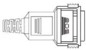
1.1) AMP (D-Sub 9Pin):
| Pin | Signal |
| 2 | Data |
| 7 | GND |
| 9 | +5VCC |
natural_image
Technical line drawing of a mechanical connector or connector (no text or symbols)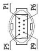
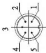
1.2) Din 5 male (240 degree):
| Pin | Signal |
| 1 | + 5VCC |
| 2 | Data |
| 3 | GND |
| 4 | N/A |
| 5 | N/A |
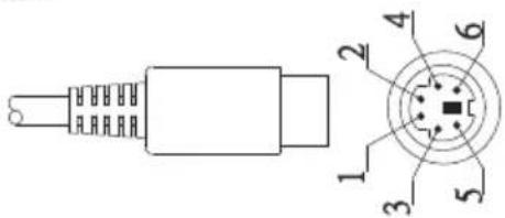
2. Keyboard Interface:
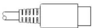
Type of connector:
2.1) PS/2 Mini Din6 Female:
| Pin | Signal |
| 1 | PC Data |
| 2 | NC |
| 3 | GND |
| 4 | +5VCC |
| 5 | PC-Clk |
| 6 | NC |
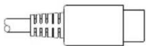
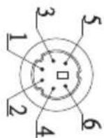
2.2) PS/2 Mini Din6 Male:
| Pin | Signal |
| 1 | KB- Data |
| 2 | NC |
| 3 | GND |
| 4 | +5VCC |
| 5 | KB-Clk |
| 6 | NC |
Type of connector:
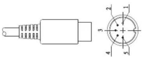
2.3) PC-AT: Din 5 Male:
| Pin | Signal |
| 1 | KB-Clk |
| 2 | KB-Data |
| 3 | NC |
| 4 | GND |
| 5 | +5VCC |
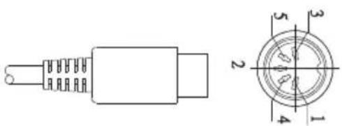
2.4) PC-AT: Din 5 Female:
| Pin | Signal |
| 1 | PC-Clk |
| 2 | PC-Data |
| 3 | NC |
| 4 | GND |
| 5 | +5VCC |
3.RS232 Interfaces:
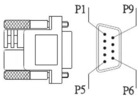
3.1) DB9F
| Pin | Signal |
| 2 | TXD(Out) |
| 3 | RXD(In) |
| 5 | GND |
| 7 | CTS(In) |
| 8 | RTS(Out) |
| 9 | +5VCC |
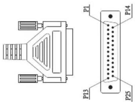
3.2) DB25F
| Pin | Signal |
| 2 | RXD(In) |
| 3 | TXD(Out) |
| 4 | CTS(In) |
| 5 | RTS(Out) |
| 7 | GND |
| 16 | +5VCC |
| 25 | +5VCC |
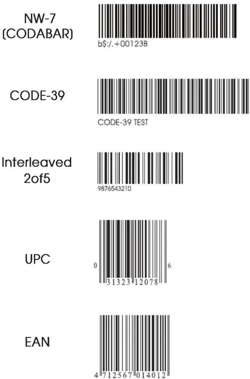
APPENDIX 3
BAR CODE TEST CHART
| DENSITY | NARROW mm(mil) | WIDE mm(mil) | CHAR.GAP mm(mil) | N/W RATIO |
| MEDIUM DENSITY | 0.25(10) 0 | 625(25) 0.25 | (10) 1/2.5 |
MEDIUM DENSITY
APPENDIX 3
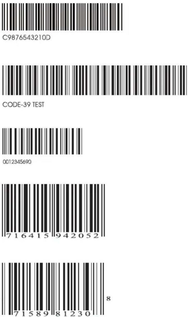
BAR CODE TEST CHART
| DENSITY | NARROW mm(mil) | WIDE mm(mil) | CHAR.GAP mm(mil) | N/W RATIO |
| LOW DENSITY | 0.33(13) 0 | 825(32.5) 0.3 | 33(13) 1/2.5 |
LOW DENSITY
- GENERAL
- SETTING GROUP(GROUP1\~14)
- SYMBOLOGY FORMATTING(GROUP15\~32)
- FULL ASCII(CODE39)TABLE, FUNCTION KEY TABLE(GROUP33\~47)
- APPENDIX
- CLONING MODE
- WHAT IS CLONING MODE?
- HOW SHOULD CLONING WORK?
- NOTES:
- FORMAT OF CLONING
- EXAMPLE :
- PROJECT ASSIGNMENTS:
- SETTING PROCEDURE:
- CORRECT SETTING
- WRONG SETTING
- HOW TO CONNECT THE SCANNER TO THE HOST TERMINAL: Handheld Barcode Scanner
- KEYBOARD WEDGE INTERFACE
- RS-232 INTERFACE
- USB INTERFACE
- HOW TO CHANGE A CABLE
- HOW TO SET PARAMETERS
- How do you program a scanner with this user's guide?
- Preamble / Postamble (maximum 16 digits)
- Min Length / Max Length
- Accuracy Adjustment
- Set Code ID (Example: Code 39)
- Set A Data - (CX-Codabar, ABC Codabar, Codabar Coupling).
- GROUP-1
- GROUP-2
- READING MODE SETTING
- GROUP-2.2
- BI-COLOR LIGHT SOURCE SETTINGS
- GROUP-2.3
- ADVANCED AUTO-SENSING MODE SETTINGS
- GROUP-2.4
- IDLE MODE SETTING
- IDLE MODE
- GROUP-2.5
- WIRELESS SCANNER SETTINGS
- GROUP-2.6
- CONNECTION OPTIONS
- GROUP-2.7
- PINCODE SETUP
- GROUP-2.8
- SET BLUETOOTH DEVICE ID
- \*Note:
- GROUP-2.9
- POWER OFF TIMEOUT
- GROUP-2.10
- iOS (Apple)
- Getting Connected
- Getting Connected without Pincode
- ENABLE SSP
- Touch Keyboard
- Android
- GROUP-2.11
- LINK QUALITY
- BATCH MODE
- GROUP-2.12
- SPP MASTER MODE
- GROUP-2.13
- SET SPP PINCODE
- GROUP-2.14
- SPP REMOTE CONTROL
- Command Response
- Beeper Response
- SHUT DOWN
- DISCONNECTION
- GROUP-2.15
- GROUP-2.16
- DATA FORMAT
- Example:
- DATE & TIME SETUP
- SET DATE
- SET TIME
- GROUP-2.17
- DATE FORMAT
- TIME FORMAT
- GROUP-3
- GROUP-4
- SETTING PROCEDURE:
- FORMAT:
- GROUP-5
- GROUP-6
- GROUP-7
- SYMBOLOGIES CODE ID IDENTIFIER, SET ID
- SET ID - SETTING PROCEDURES
- Setting steps:
- GROUP-8
- GROUP-9
- CODE ID CONFIGURATION: SET ID
- RESET
- GROUP-10
- GROUP-11
- NOTE:
- GROUP-12
- GROUP-13
- GROUP-14
- WAND EMULATION PARAMETER SETTING
- GROUP-15
- ENABLE/ DISABLE SYMBOLOGIES
- ENABLE
- DISABLE
- GROUP-16
- GROUP-17
- CHINA POSTAL CODE [ TOSHIBA CODE ]
- FULL ASCII (Code 39) NUMERIC TABLE
- SETTING PROCEDURE
- MIN / MAX LENGTH
- GROUP-18
- GROUP-19
- GROUP-20
- GROUP-21
- GROUP-22
- CLSI FORMAT
- GROUP-23
- REMARK:
- GROUP-24
- ADJACENT REQUIRED
- SETTING PROCEDURE - SET INSERT DATA
- GROUP-25
- GROUP-26
- GROUP-27
- GROUP-28
- GROUP-29
- GROUP-30
- GROUP-31
- NOTES: DEFINE EAN 128
- GROUP-32
- GROUP-33
- GROUP-34
- GROUP-35
- GROUP-36
- GROUP-37
- GROUP-38
- GROUP-39
- GROUP-40
- FULL ASCII TABLE ( CODE 39 ) LOWER CASE ALPHABETS
- GROUP-41
- GROUP-42
- GROUP-43
- FULL ASCII TABLE ( CODE 39 ) NAVIGATION KEYS
- GROUP-44
- FULL ASCII TABLE ( CODE 39 ) MODIFIER KEYS
- INCORRECT INTERFACE CONNECTION INCORRECT CONFIGURATION SETUP POOR BARCODE QUALITY
- GENERAL PROCEDURES
- KEYBOARD INTERFACES PROBLEMS
- Do you have the correct cable?
- Does the keyboard work?
- Can your computer accept the data fast enough?
- Does keyboard port supply enough power?
- Is the proper symbology enabled?
- Does the selected bar code symbology configuration match the bar code(s) being read?
- POOR BAR CODE QUALITY
- TOLERANCE OF BAR CODE
- LABELS (PAPER & COLOR & PRINTER)
- APPENDIX 1
- DEFAULT TABLE 1
- DEFAULT TABLE 2
- DEFAULT TABLE 3
- DEFAULT TABLE 4
- APPENDIX 2
- Cable Pin Assignment
- INTERFACES:
- TTL, Wand Emulation
- Keyboard Interface:
- 3.RS232 Interfaces:
- APPENDIX 3
- BAR CODE TEST CHART
Brand : Unitech
Model : MS146-IUCB0M-SG
Category : Barcode scanners