
MS926P - Barcode scanners Unitech - Free user manual and instructions
Find the device manual for free MS926P Unitech in PDF.


| Product Type | Barcode Scanner |
| Brand | Unitech |
| Model | MS926P |
| Scan Engine | 2D Imager |
| Barcode Symbologies | 1D, 2D, QR, Data Matrix, PDF417 |
| Interface | USB, RS-232, optional Bluetooth |
| Dimensions (L x W x H) | 10.0 cm x 6.5 cm x 3.5 cm |
| Weight | 150 g |
| Power Supply | 5V DC via USB, <300 mA |
| Scan Rate | Up to 200 scans per second |
| Read Range | 0 to 30 cm (depending on code size) |
| Light Source | LED illumination (white) |
| Operating Temperature | 0°C to 50°C (32°F to 122°F) |
| Drop Resistance | 1.5 m onto concrete |
| Ingress Protection | IP42 |
| Maintenance | Clean lens with soft cloth; avoid solvents |
| Safety | Class 1 LED product; no laser hazard |
| Spare Parts | USB cable, trigger assembly, connector cable |
| Reparability | Modular design; replaceable cable and trigger |
Frequently Asked Questions - MS926P Unitech
User questions about MS926P Unitech
0 question about this device. Answer the ones you know or ask your own.
Ask a new question about this device
Download the instructions for your Barcode scanners in PDF format for free! Find your manual MS926P - Unitech and take your electronic device back in hand. On this page are published all the documents necessary for the use of your device. MS926P by Unitech.
USER MANUAL MS926P Unitech
Wireless 2D Pocket Scanner
- MS926P -
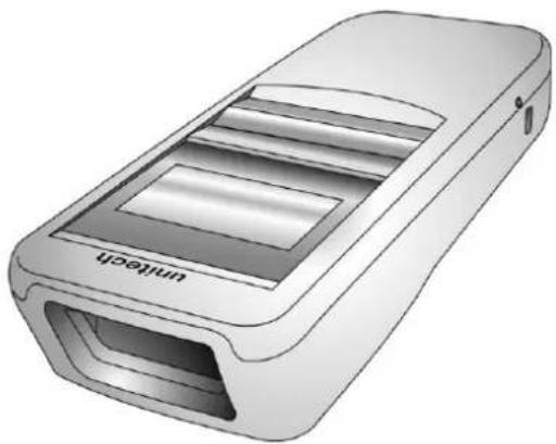
natural_image
Illustration of a handheld electronic device labeled 'unitech' (no additional text or symbols)User's Manual
Version 1.5
Change Log
| Date | Change Description | Version |
| 20190401 | first published version | 1.0 |
| 20190625 | Update 1.7 | 1.1 |
| 2020/6/16 | Update manual | 1.2 |
| 2020/06/22 | Update note for screen burn in effect | 1.3 |
| 20211203 | Update 4.2.4 Power Saving | 1.4 |
| 20220726 | Change Hand Strap into Wrist Lanyayd | 1.5 |
Preface
About This Manual
Thank you for purchasing the Unitech product.
This manual explains how to install, operate and maintain our product.
No part of this publication may be reproduced or used in any form, or by any electrical or mechanical means, such as photocopying, recording, or information storage and retrieval systems, without permission in writing from the manufacturer. The material in this manual is subject to change without notice. All product and company names are trademarks, service marks, or registered trademarks of their respective owners.
Regulatory Compliance Statements

FCC Warning Statement
This device has been tested and found to comply with the limits for a Class B digital device, pursuant to part 15 of the FCC rules. These limits are designed to provide reasonable protection against harmful interference in a residential installation. This equipment generates, uses and can radiate radio frequency energy and, if not installed and used in accordance with the instructions, may cause harmful interference with radio communications. However, there is no guarantee that interference will not occur in a particular installation. If this equipment does cause harmful interference with radio or television reception, which can be determined by turning the equipment off and on, the user is encouraged to try to correct the interference by one or more of the following measures:
Enter Setup
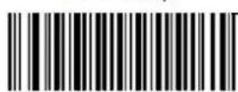
-Reorient or relocate the receiving antenna.
Exit Setup
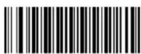
i
© 2022 Unitech Electronics Co., Ltd. All rights reserved. Unitech is a registered trademark of Unitech Electronics Co., Ltd.
—Increase the separation between the equipment and receiver.
-Connect the equipment into an outlet on a circuit different from that to which the receiver is connected.
-Consult the dealer or an experienced radio/TV technician for help.
- This transmitter must not be co-located or operating in conjunction with any other antenna or transmitter.
- This device complies with FCC RF radiation exposure limits set forth for an uncontrolled environment. To maintain compliance with FCC RF exposure requirements, avoid direct contact to the transmitting antenna during transmitting.
- Any changes or modifications (including the antennas) made to this device that are not expressly approved by the manufacturer may void the user's authority to operate the equipment.
Operation on the 5.15 - 5.25GHz frequency band is restricted to indoor use only. The FCC requires indoor use for the 5.15-5.25GHz band to reduce the potential for harmful interference to co-channel Mobile Satellite Systems. Therefore, it will only transmit on the 5.25-5.35 GHz, 5.47-5.725 GHz and 5.725 - 5.850 GHz band when associated with an access point (AP).
FCC Label Statement
This device complies with part 15 of the FCC rules. Operation is subject to the following two conditions:
- This device may not cause harmful interference.
- This device must accept any interference received, including interference that may cause undesired operation.
RF Radiation Exposure Statement
For body contact during operation, this device has been tested and meets FCC RF exposure guidelines when used with an accessory that contains no metal and that positions the handset a minimum of 1.5 cm from the body.
Use of other accessories may not ensure compliance with FCC RF exposure guidelines.
Canadian Compliance Statement
This Class B Digital apparatus meets all requirements of the Canadian Interference-Causing Equipment Regulations.
European Conformity Statement
Unitech Electronics co., Ltd herewith declares that the Unitech product is in compliance with the essential requirements and all other provisions of the RED 2014/53/EU directive, the EMC 2014/30/EU directive and the Low Voltage 2014/35/EU directive.
The declaration of conformity is available for download at : https://portal.Unitech.eu/public/Safetyregulatorystatement
CE RF Exposure Compliance
This device meets EU requirements (2014/53/EU) on the limitation of exposure of the general public to electromagnetic fields by way of health protection. For body-worn operation, this device has been tested and meets the ICNIRP guidelines and the European Standard EN 62209-2, for use with dedicated accessories, SAR is measured with this device at a separation of 0.5cm to the body, while transmitting at the highest certified output power level in all frequency bands of this device. Use of other accessories which contain metals may not ensure compliance with ICNIRP exposure guidelines.
CE Mark Warning
CE
This equipment complies with the requirements of Directive 2014/53/EU of the European Parliament and Commission from 24 May, 2014 governing Radio and Telecommunications Equipment and mutual recognition of conformity.
RoHS Statement
unitech
Green Product

This device conforms to RoHS (Restriction of Hazardous Substances) European Union regulations that set maximum concentration limits on hazardous materials used in electrical and electronic equipment.
Waste electrical and electronic equipment (WEEE)

Unitech has set up a policy and process to meet the EU directive 2002/96/EC and update 2003/108/EC concerning electronic waste disposal.
For more detailed information of the electronic waste disposal of the products you have purchased from Unitech directly or via Unitech's resellers, you shall either contact your local supplier or visit us at : https://portal.Unitech.eu/public/WEEE
Taiwan NCC Warning Statement
低功率電波輻射性電機管理辦法
The Unitech product is certified in the U.S. to conform to the requirements of DHHS/CDRH 21CFR Subchapter J and to the requirements of IEC 825-1. Class II and Class 2 products are not considered to be hazardous. The Unitech product contains internally a Visible Laser Diode (VLD) whose emissions do not exceed the maximum limits as set forth in the above regulations. The scanner is designed so that there is no human access to harmful laser light during normal operation, user maintenance or prescribed service operations.
The laser safety warning label required by the DHHS/IEC for the Unitech product's optional laser scanner module is located on the memory compartment cover, on the back of the unit.
* Laser information only applies to the products with laser components.
CAUTION! Use of controls or adjustments or performance of procedures other than those specified herein may result in hazardous laser light. Use of optical instruments with the scanner, including binoculars, microscopes, and magnifying glasses, with will increase eye damage. This does not include eyeglasses worn by the user.
LED Information
The Unitech product contains LED indicator(s) or LED ring whose luminance is not harmful to human eyes during normal operation, user maintenance or prescribed service operations.
*LED information only applies to the products with LED components.
Battery Notice
- To guarantee optimal performance, it is recommended that rechargeable batteries be replaced every year, or after 500 charging cycles are completed. It is normal for the battery to balloon or expand after one year or 500 cycles. Although it does not cause damage, it cannot be used again and must be disposed of according to the location's safe battery disposal procedures.
- If a battery performance decreases more than 20%, the battery is at the end of its life cycle. Stop use and ensure the battery is disposed of properly.
-
The length of time that a battery lasts depends on the battery type and how the device is used. Conserve the battery life by doing the following:
-
Avoid fully uncharging the battery because this places additional strain on it. Several partial uncharges with frequent charges are better than a fully uncharged battery. Charging a partially charged battery does not cause harm to the unit.
- Keep the battery cool. Avoid hot vehicles. For prolonged storage, keep the battery at a 40% charge level.
-
Do not leave the battery uncharged and unused for an extended period of time, the battery will wear out and the longevity of the battery will be at least half of one with frequent charges.
-
Protect battery life by not over or under charging the battery.
-
Please do not leave battery unused for long time without charging it. Despite Unitech's safety precautions, the battery pack may begin to change shape. If so, stop using it immediately. Please check to see if you are using a proper power adapter to charge the battery or contact your service provider for service.
-
If you cannot charge the battery after it has been idle for an extended period of time and it begins to heat up, please do not try to charge it. It may not be functional anymore.
-
Please only use the original battery from Unitech. Using a third party battery can damage our products. Please note that when such damage occurs, it is not covered by your warranty.
CAUTION!
- RISK OF EXPLOSION IF BATTERY IS REPLACED INCORRECTLY. DISPOSE OF USED BATTERIES ACCORDING TO THE INSTRUCTIONS.
Battery charge notice
It is important to consider temperature when the battery pack is charging. Charging is most efficient at normal room temperature or in a slightly cooler environment. It is essential that batteries are charged within the stated range of 0°C to 40°C. Charging batteries outside of the specified range could damage the batteries and shorten their life cycle.
CAUTION! Do not charge batteries at a temperature lower than 0°C. This will and make the batteries unstable and dangerous. Please use a battery temperature detecting device for a charger to ensure a safe charging temperature range.
CAUTION! To ensure the unit working properly, please keep all connectors away from the contaminants staying inside of them such as dust, grease, mud, and water. The negligence may cause the unit with no communication, short circuited, overheated and so on.
CAUTION! If the connector is damaged, please ensure the connector is being fully repaired before use the unit to avoid causing short circuited.
Storage and safety notice
Although charged batteries may be left unused for several months, their capacity may be depleted due to build up of internal resistance. If this happens, they will require recharging prior to use. Batteries may be stored at temperatures between -20°C to 60°C, however they may deplete more rapidly at higher temperatures. It is recommended to store batteries at room temperature.
* The message above only applies to the usage of the removable batteries. For the products with non-removable batteries / without batteries, please refer to the specification of each product.
Product Operation and Storage Notice
The Unitech product has applicable operation and storage temperature conditions. Please follow the limitation of suggested temperature conditions to avoid failure, damage or malfunction.
*For applicable temperature conditions, please refer to the specification of each product.
Adapter Notice
- Please do not leave the power adapter in the socket when it is not connected to your Unitech product for charging.
- Please remove the power adapter when the battery is fully recharged.
- The bundled power adapter that comes with your Unitech product is not meant to be used outdoors. An adapter exposed to water or rain, or a very humid environment can cause damage to both the adapter and the product.
- Please only use the bundled power adapter or same specification of adapter to charge your Unitech product. Using the wrong power adapter can damage your Unitech product.
* The message above only applies to the product connected to the adapter. For the products without using the adapters, please refer to the specification of each product.
Hearing Damage Warning
Zx.3 Warning
The warning shall be placed on the equipment, or on the packaging, or in the instruction manual and shall consist of the following:
- the symbol of Figure 1 with a minimum height of 5mm ; and
- the following wording, or similar :
To prevent possible hearing damage, do not listen at high volume levels for long periods.
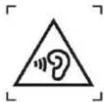
Figure 1 – Warning label (IEC 60417-6044)
Alternatively, the entire warning may be given through the equipment display during use, when the user is asked to acknowledge activation of the higher level.
Worldwide Support
Unitech's professional support team is available to quickly answer questions or assist with technical-related issues. Should an equipment problem occur, please contact the nearest Unitech regional service representative.
For complete contact information please visit the Web sites listed below:
| Taipei, Taiwan – Headquarters | Europe |
| Tel: +886-2-89121122E-mail: info@hq.ute.comAddress: 5F, No. 136, Lane 235, Baoqiao Road, Xindian District, New Taipei City 231, Taiwan (R.O.C.)Website: http://www.ute.com | Tel: +31-13-4609292E-mail: info@eu.ute.comAddress: Kapitein Hatterasstraat 19, 5015 BB,Tilburg, the NetherlandsWebsite: http://eu.ute.com |
| China | Japan |
| Tel: +86-59-2310-9966E-mail: info@cn.ute.comAddress: Room401C, 4F, RIHUA International Mansion,Xinfeng 3nd Road, Huoju Hi-tech District,Xiamen, Fujan , ChinaWebsite: http://cn.ute.com | Tel: +81-3-35232766E-mail: info@jp.ute.comAddress: Kayabacho Nagaoka Building 8F.,1-5-19Shinkawa, Chuo-Ku,Tokyo, 104-0033, JapanWebsite: http://jp.ute.com |
| Asia & Pacific / Middle East | Latin America |
| Tel: +886-2-27911556E-mail: info@apac.ute.cominfo@india.ute.cominfo@mideast.ute.comAddress: 4F., No. 236, ShinHu 2nd Rd.,NeiHu Chiu, 114, Taipei,TaiwanWebsite: http://apac.ute.com / http://mideast.ute.com | Tel: +52-55-5171-0528E-mail: info@latin.ute.comAddress: 17171 Park Row, Suite 210Houston, TX 77084USA (Rep.)Website: http://latin.ute.com |
| North America | Please scan QR Code to visit us : |
| Tel: +1-714-8926400E-mail: info@us.ute.com / info@can.ute.comAddress: 6182 Katella Ave, Cypress, CA 90630, USAWebsite: http://us.ute.com |  |
Enter Setup
Exit Setup
xi
© 2022 Unitech Electronics Co., Ltd. All rights reserved.
Unitech is a registered trademark of Unitech Electronics Co., Ltd.
Warranty Policy
The items covered under the Unitech Limited Warranty are free from defects during normal use.
The warranty period is varied from each country. Please consult with your supplier or Unitech local office for actual length of warranty period to your purchased product.
Warranty becomes void if equipment is modified, improperly installed or used, damaged by accident or neglect, or if any parts are improperly installed or replaced by the user.
Table of Contents
Preface....i
About This Manual ....i
Regulatory Compliance Statements ...... i
Laser Information ...... vi
LED Information ...... vi
Battery Notice.... vii
Adapter Notice....x
Hearing Damage Warning....x
Worldwide Support....xi
Warranty Policy....xii
Chapter 1 - Overview....1
1.1 Package .... 1
1.2 Scanner Detail....2
1.3 Specifications ....4
1.4 Getting Started ....7
1.5 Battery Charging 9
1.6 LED Indicator / Beeper Sequence 10
1.7 Display Menu Tree .... 11
Chapter 2 - Installation....20
2.1 Scanner Type ....20
Chapter 3 – Symbology ......22
3.1 All symbologies....22
3.2 Enable/Disable 1D / 2D Symbologies....22
3.3 1D....23
3.4 2D....68
Chapter 4 – Command Settings....77
4.1 Operation Mode....77
4.2 System setting....78
4.3 RF Config.....80
Enter Setup 4.4 Data & Memory 81
Exit Setup
xiii
© 2022 Unitech Electronics Co., Ltd. All rights reserved.
Unitech is a registered trademark of Unitech Electronics Co., Ltd.
4.5 Data Sending Block Delay....83
4.6 HID Keyboard Character Delay 84
4.7 Beep & Vibration & Indicators....87
4.8 Data Terminator 92
4.9 1:1 / 1:N Checking Indicators ....93
Appendix A – Parameter Programming Examples .....95
Appendix B - Digit Barcodes....101
Appendix C - Save/Cancel Barcodes....103
Chapter 1 - Overview
1.1 Package
Please make sure the following contents are in the MS926P gift box. If something is missing or damaged, please contact your Unitech representative.
The standard package contents
■ MS926P Scanner
■ Quick Reference Guide
■ Micro USB to USB Cable
■ Wrist Lanyard
■ USB Dongle
Optional accessories
■ 1-Slot Charging cradle
■ 5-Slot Charging cradle
■ USB Power Adapter
NOTE: ● The barcode with an asterisk (*) which appears in the following chapters indicates that it is the default option for the corresponding setting.
1.2 Scanner Detail
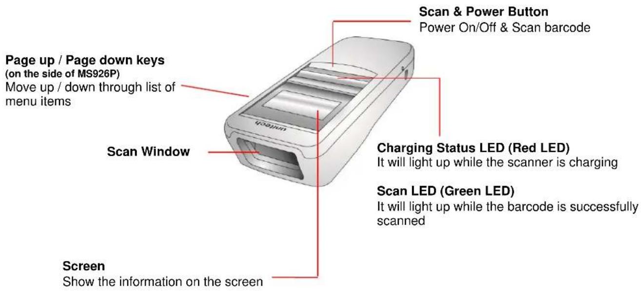
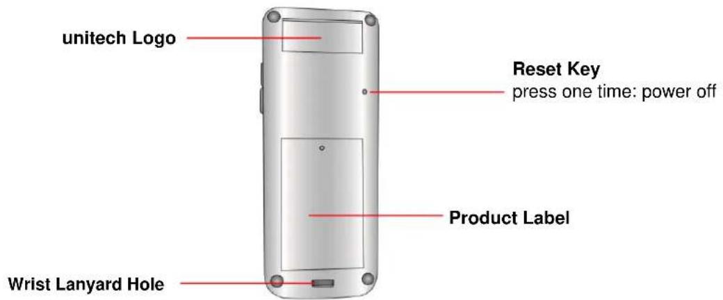
Enter Setup
Exit Setup
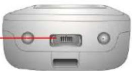
Micro USB Connector
For scanner charging and data transmission
1.3 Specifications
System
| Display | 1" OLED, 128 x 64 |
| OS | Proprietary, Connect to host with Windows |
| Memory | 64 Kbytes SRAM / 2 MB Flash ROM |
| Key | 3 Keys: Page Up, Page Down, Scan with power on/off feature |
Optical & Performance
| Receiving Device | 752×480 CMOS | |||
| Illumination & Aiming | Red LED 625nm±10nm, Laser diode 650nm | |||
| Aiming | Laser diode 650nm | |||
| Ambient light | 0~100,000 lux | |||
| Symbol Contrast | ≥20% | |||
| Roll Angle | 360 degrees | |||
| Field of View | Horizontal 36°, Vertical23° | |||
| Skew Angle | ±55 | |||
| Pitch Angle | ±55 | |||
| Depth of Field (DOF PCS=80%) | Symbology | Density | Near | Far |
| EAN-13 | 13 mils | 6.0 cm | 29 cm | |
| Code 39 | 5 mils | 5.5 cm | 16.5 cm | |
| PDF417 | 6.7 mils | 5.5 cm | 13.5 cm | |
| Data Matrix | 10 mils | 5.5 cm | 13 cm | |
| QR | 15 mils | 4.5 cm | 17.5cm | |
| Environmental | |
| ESD Protection | Functional after 8K Contact and 12K Air |
| Mechanical Shock | 1.5m onto concrete (scanner only) |
| IP Rate | IP42 |
| Operating Temperature | 0°C to 50°C |
| Storage Temperature | -30°C to 70°C |
| Relative Humidity | 95% non-condensing |
| Functionality (Symbologies) | |
| 1D Code | Code 128, EAN-13, EAN-8, Code 39, UPC-A, UPC-E, Codabar, Interleaved 2 of 5, ITF-6, ITF-14, ISBN, Code 93, UCC/EAN-128, GS1 Databar, Matrix 2 of 5, Code 11, Industrial 2 of 5, Standard 2 of 5, Plessey, MSI-Plessey, etc. |
| 2D Code | PDF417, Data Matrix (ECC200, ECC000, 050, 080, 100, 140), QR Code, Chinese Sensible Code |
| Operation Mode | Trigger mode, Presentation mode, Auto mode, Batch mode, Wedge mode |
| Electrical | |
| Operation Voltage | DC 3V to 5V |
| Current Consumption | Operate: 300mA, Standby: 70mA |
| Battery Type | Rechargeable Li-ion battery |
| Battery Capacity | 680 mAh |
| Battery Charging time | Fully charged in about 4 hours |
| Operating Time | 9 hours at condition of 1 scan/5 sec |
| Communication | |
| Radio Frequency | Unlicensed 2.4GHz |
| Protocol | Wireless SPP & HID profiles |
| Range | Up to 10M (Open space) |
| Host Interface supported | Micro USB |
| Mechanical | |
| Scanner Dimension | 36.9mm x 95.9mm x 21.1mm |
| Scanner Weight | 63g |
| Switch life | 10 million times |
| Regulation Approvals | |
| CE, FCC, BSMI, VCCI | |
1.4 Getting Started
To turn on the scanner, press and hold the Scan & Power Button for about 2 seconds. To turn off the scanner, press and hold the Scan & Power Button for about 5 seconds.
After powering on, you will see the following screen on the scanner display.
The scanner is now under standby mode. Now you can scan the desired barcode or start the BT pairing mode.
The standby display will show the current Battery Status, Scanner Type, Operation Mode, and Time.
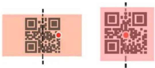
The aiming beam can be centered over the bar code with any direction and have the proper alignment for a good read. (see example below)
1.4.1 Connect Dongle to Host
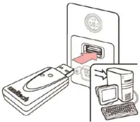
Plug the USB Dongle to a free USB port of a host computer. The MS926P is now ready to use.
1.5 Battery Charging
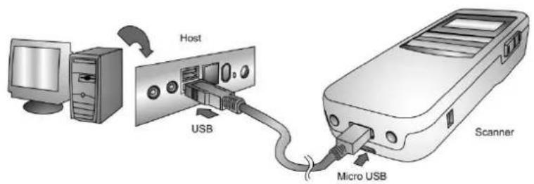
Insert the Micro USB connector into the port on the scanner and the standard USB connector of the USB cable into a USB port on the host PC.
1.6 LED Indicator / Beeper Sequence
| Division | Action/Status | LED for Barcode reading & Communication | LED for Battery status | Beep / Sound |
| Power On | Green & Red Lights blink once | One High Beep | ||
| Auto Power Off | Long press trigger key for 5 seconds | Three short beeps at 15 seconds before power off | ||
| USB connection | Low- Medium –High Beeps | |||
| USB disconnection | High- Medium –Low Beeps | |||
| Barcode reading | Wedge & Auto (When BT Connect) | Green Light blinks once | One Beep | |
| Batch | Green Light blinks once | One short Beep | ||
| Wedge & Auto (When BT Disconnect) | Green Light blinks once | One short Beep | ||
| Data sent to PC | Data sent to PC successfully (Batch) | Green Light blinks once | Dee-Du sound | |
| Fail sent data to PC (Batch) | Red Light blinks once | Dee-Dee-Dee sound | ||
| Data delete | Green Light blinks once | |||
| All Data delete | Deleting-Green light always on | |||
| RF connection | Low- Medium –High Beeps | |||
| RF disconnection | High- Medium –Low Beeps | |||
| Low Battery Alarm (<10%) | (USB charging cable disconnected) | Blinking Red Light | ||
| Battery charging | (USB charging cable connected) | Red light always on | ||
| Battery Fully charged | (USB charging cable connected) | Green light always on |
Enter Setup
Exit Setup
1.7 Display Menu Tree
To enter main menu of MS926P, press and hold Page Down key and then press Page Up key for 5 seconds. (During one handed operation, you can press the area in between Page Down key and Page Up key to enter the main menu.)
You will see the following screen on the MS926P display. Now you can use Page Up/Down button to scroll through the menu and use Scan button to make your selection.
| Top Menu | Sub Menu Level 1 | Sub Menu Level 2/Options/Result | Options/Result | Default Setting |
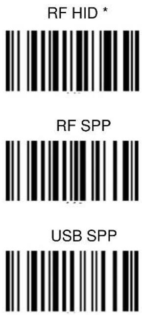
| General Setting | 1. Scanner Type | 1.1 RF HID | n/a | RF HID |
| 1.2 USB SPP | ||||
| 1.3 RF SPP | ||||
| 2. Operation Mode | 2.1 Wedge Mode | n/a | Auto Mode | |
| 2.2 Batch Mode | ||||
| 2.3 Auto Mode | ||||
| 3. Date/Time | 3.1 View Date/Time | Show Date/Time | 2014-01-01 08:00:00 | |
| 3.2 Set Date/Time | Set Date/Time | |||
| 3.3 Time Display | 3.3.1 Auto | Auto | ||
| 3.3.2 Always | ||||
| 3.4 Exit | n/a | |||
| 4. Power | 4.1 Power Saving | Disable/30/20/15 /10/5 Sec. | 15 Sec. | |
| Manager | 4.2 Auto Power Off | Disable/30/20/15 /10/5/3/1 Min. | 15 Min. | |
| 4.3 Exit | n/a | |||
| 5. Setup By Label | 5.1 Enable | n/a | Enable | |
| 5.2 Disable | ||||
| 6. FAC Default | 6.1 Restore to FAC Default? Yes/No | Save to Selected Customer Setting | No | |
| 7. FW Version | 7.1 Show Firmware Version V x.x | n/a | ||
| 8. Serial Number | 8.1 Show SERIAL NUMBER XXXXXXXXX | n/a | n/a | |
| 9. Exit | n/a | n/a | n/a | |
| Data & Memory | 1. View / Edit Buff. | 1.1. Show Buffer Data | 1.1.1 Exit / Erase/ View | ■ If choose Exit, back to DATA/MEMORY Page■ If choose Erase, delete data■ If choose View, continue to view the buffer data■ For Auto/Batch mode, pressing [ENTER]+[Down] / [ENTER]+[UP] keys to view data longer than 3 lines |
| 2. Erase Buffer | 2.1. Erase Buffer Yes/ No | Erase entry if Yes selected | No | |
| 3. Free MEM Space | 3.1 Show FREE BUFFER MEM | n/a | ||
| 4. Data Separator | 4.1 CR | CR | ||
| 4.2 None | ||||
| 4.3 TAB | ||||
| 4.4 CRLF | ||||
| 4.5 LF | ||||
| 5. Sending BlkDly | 5.1 Sending BlkDelay10ms/3 Sec./1Sec./500 ms./100ms./50 ms. | 10ms | ||
| 6. Date/Time Stamp | 6.1 DATE STAMPDisableDDMMYYYYDD.MM.YYYYYDD/MM/YYYYDD-MM-YYYYMMDDYYYYMM.DD.YYYYYMM/DD/YYYYMM-DD-YYYYYYYYMMDDYYYY.MM.DDYYYYMM-DD/YYYYYYYYMM-DDYYYYMM-DDYYYYMM-DDYYYYMM-DDYYYYMM-DDYYYYMM-DDYYYYMM-DDYYYYMM-DDYYYYMM-DDYYYYMM-DDYYYYMM-DDYYYYMM-DDYYYYMM-DDYYYYMM-DDYYYYMM-DDYYYYMM-DDYYYYMM-DDYYYYMM-DDYYYYMM-DDYYYYMM-DDYYYYMM-DDYYYYMM-DDYYYYMM-DDYYYYMM-DDYYYYMM-DDYYYYMM-DDYYYYMM-DDYYYYMM-DDYYYYMM-DDYYYYMM-DDYYYYMM-DDYYYYMM-DDYYYYMM-DDYYYYMM-DDYYMM-DDYYYYMM-DDYYYYMM-DDYYYYMM-DDYYYYMM-DDYYYYMM-DDYYYYMM-DDYYYYMM-DDYYYYMM-DDYYYYMM-DDYYYYMM-DDYYYYMM-DDYYYYMM-DDYYYYMM-DDYYYYMM-DDYYYYMM-DDYYYYMM-DDYYYYMM-DDYYYYMM-DDYYYYMM-DDYYYYMM-DDYYYYMM-DDYYYYMM-DDYYYYMM-DDYYYYMM-DDYYYYMM-DDYYYYMM-DDYYYYMM-DDYYYYMM-DDYYYYMM-DDYYYYMM-DDYYYYMM-DDYYYYMM-DDYYYYmm-DDYYYYMM-DDYYYYMM-DDYYYYMM-DDYYYYMM-DDYYYYMM-DDYYYYMM-DDYYYYMM-DDYYYYMM-DDYYYYMM-DDYYYYMM-DDYYYYMM-DDYYYYMM-DDYYYYMM-DDYYYYMM-DDYYYYMM-DDYYYYMM-DDYYYYMM-DDYYYYMM-DDYYYYMM-DDYYYYMM-DDYYYYMM-DDYYYYMM-DDYYYYMM-DDYYYYMM-DDYYYYMM-DDYYYYMM-DDYYYYMM-DDYYYYMM-DDYYYYMM-DDYYYYMM-DDYYYYMM-DDYYYYMM-DDYYYYMM-DDDYYYYMM-DDYYYYMM-DDYYYYMM-DDYYYYMM-DDYYYYMM-DDYYYYMM-DDYYYYMM-DDYYYYMM-DDYYYYMM-DDYYYYMM-DDYYYYMM-DDYYYYMM-DDYYYYMM-DDYYYYMM-DDYYYYMM-DDYYYYMM-DDYYYYMM-DDYYYYMM-DDYYYYMM-DDYYYYMM-DDYYYYMM-DDYYYYMM-DDYYYYMM-DDYYYYMM-DDYYYYMM-DDYYYYMM-DDYYYYMM-DDYYYYMM-DDYYYYMM-DDYYYYMM-DDYYYYMM-DDYYYYMM-DDYYYYMM-DDXXXXMM-DDYYYYMM-DDYYYYMM-DDYYYYMM-DDYYYYMM-DDYYYYMM-DDYYYYMM-DDYYYYMM-DDYYYYMM-DDYYYYMM-DDYYYYMM-DDYYYYMM-DDYYYYMM-DDYYYYMM-DDYYYYMM-DDYYYYMM-DDYYYYMM-DDYYYYMM-DDYYYYMM-DDYYYYMM-DDYYYYMM-DDYYYYMM-DDYYYYMM-DDYYYYMM-DDYYYYMM-DDYYYYMM-DDYYYYMM-DDYYYYMM-DDYYYYMM-DDYYYYMM-DDYYYYMM-DDYYYYMM-DDYYYYMM-DDYYYYMHHH:MM:SSAM:HH:MM:SS | Disable | Disable | |
| 6.2 TIME STAMPDisable/HHMMAM/HHMM/HH:MM AM/HH:MM/HHMMSSAM/HHMMSS/HH:MM:SSAM/HH:MM:SS | Disable | Disable | ||
| 7. Data Validation | 7.1 Disable | Disable /Enable | Disable | |
| 7.2 1:N Checking | CHECKING START POSITION | CHECKING LENGTH | ||
| 7.2 1:1 Checking | CHECKING START POSITION | CHECKING LENGTH | ||
| 7.3 Lookup Table | Download Lookup | |||
| 8. Exit | n/a | n/a | n/a |
| Top Menu | Menu | Result | Default Setting |
| RF INFO | 1. RF Address | 1.1 RF MAC ADDR | |
| 2.RF Remove | 2.1 Erase ? YES / NO | ||
| 3. Exit |
| Top Menu | Menu | Result | Result | Default Setting |
| Beep & Vibrate | 1. Beeper Volume | 1.1 Medium/ Low/ Mute/ High | Medium | |
| 2. Vibrator | 2.1 Disable/ Enable | Disable | ||
| 3. Indicators | 3.1 Good Read | 3.1.1 Beeper & Vibrator VibratorBeeper / None | Beeper & Vibrator | |
| 3.2 Connection | 3.2.1 Beeper & Vibrator VibratorBeeper / None | Beeper & Vibrator | ||
| 3.3 Button | 3.3.1 Beeper & Vibrator VibratorBeeper / None | Beeper & Vibrator | ||
| 3.4 System Setting | 3.4.1 Beeper & Vibrator VibratorBeeper / None | Beeper | ||
| 3.5 System Warn/ Err | 3.5.1 Beeper & Vibrator VibratorBeeper / None | Beeper | ||
| 3.6 PwrOn | 3.6.1 Beeper & Vibrator VibratorBeeper / None | Beeper & Vibrator | ||
| 3.7 PwrOff Alarm | 3.7.1 Beeper & Vibrator VibratorBeeper / None | Beeper & Vibrator | ||
| 3.8 Checking Pass | 3.8.1 1:1 / 1:N Checking Pass IndicatorBeeper & VibratorVibratorBeeper / None | Beeper | ||
| 3.9 Checking Fail | 3.9.1 1:1 / 1:N Checking Fail IndicatorBeeper & VibratorVibratorBeeper / None | Beeper | ||
| 3.10 Exit | n/a | n/a | ||
| 4. Exit | n/a | n/a | n/a |
| Top Menu | Menu | Sub Menu | Options |
| Barcode Setting | 1. 1D Barcodes | ON / OFF | 2.1 UPC-A |
| 2.2 UPC-E | |||
| 2.3 EAN-8 | |||
| 2.4 EAN-13 | |||
| 2.5 CODE 39 | |||
| 2.6 CODE 128 | |||
| 2.7 GS1 128 | |||
| 2.8 I 2 of 5 | |||
| 2.9 NEC 2 of 5 | |||
| 2.10 CODE 93 | |||
| 2.11 Codabar | |||
| 2.12 Code 11 | |||
| 2.13 Matrix 2 of 5 | |||
| 2.14 ITF-14 | |||
| 2.15 ITF-16 | |||
| 2.16 ATM-128 | |||
| 2.17 ISSN | |||
| 2.18 ISBN | |||
| 2.19 Industrial 2 of 5 | |||
| 2.20 Standard 2 of 5 | |||
| 2.21 MSI PLESSEY | |||
| 2.22 PLESSEY | |||
| 2.23 Exit | |||
| 2. 2D Barcodes | ON / OFF | 3.1 QR Code | |
| 3.2 PDF 47 | |||
| 3.3 Data Matrix | |||
| 3.4 Chinese Sensible | |||
| 3.5 Micro QR | |||
| 3.6 Exit | |||
| 3. Exit | n/a |
| Top Menu | Sub MenuLevel 1 | Result | DefaultSetting |
| HIDKeyboard | 1. KBDLanguage | 1.1 US English / Japanese / Partial ALTDanish/ ALT Mode/ French / GermanItalian / Norwegian / Spanish /Swedish/ Swiss/ UK English | US English |
| 2. KBD Case | 2.1 Auto Trace / Upper/ Lower | Auto Trace | |
| Setting | 3. KBD ChrDelay | 3.1 1ms/ 100ms/ 50ms/ 20ms/ 10ms/ 5ms | 1ms |
| 4. Exit | n/a | n/a |
Chapter 2 - Installation
2.1 Scanner Type
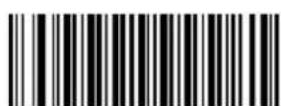
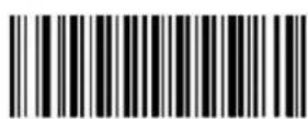
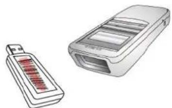
Step 1. Scan the barcode on the dongle.
natural_image
Illustration of two electronic devices: a battery and a handheld device (no text or symbols visible)Step 2. Plug the USB Dongle to a free USB port of a host computer.
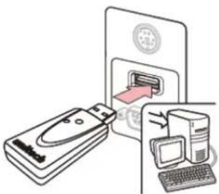
natural_image
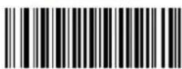
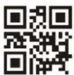
Illustration of a computer setup with a remote control unit, keyboard, and monitor (no text or symbols)Step 3. Open a word processing program such as Microsoft Word or Notepad and scan the following barcode. If the word "Unitech" appears on the screen you have successfully installed your scanner.
NOTE:
● The MS926P should be recognized as a generic HID device by your host device, similar to a standard keyboard. This allows you to scan into any field you could normally type into.
- If the MS926P is out of RF transmitting range from the host device, it will automatically save any scan data in its buffer memory and automatically upload the scan data to the host when back in RF transmitting range.
- The MS926P can also operate in Batch Mode, where a RF transmitting connection is not required. In Batch Mode, the MS926P saves all scan data in internal memory and then uploads the data when connected to a host. See back page of this guide for more information about modes and settings.
Enter Setup
Exit Setup
Chapter 3 – Symbology
3.1 All symbologies
If the Disable All Symbologies feature is enabled, the engine will not be able to read any non-programming barcodes except the programming barcodes.
All Symbologies On
All Symbologies Off
3.2 Enable/Disable 1D / 2D Symbologies
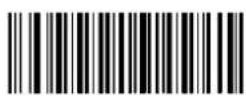
3.2.1 Enable/Disable 1D Symbologies
If the Disable 1D Symbologies feature is enabled, the engine will not be able to read any 1D barcodes.
Enable 1D Symbologies
Disable 1D Symbologies
3.2.2 Enable/Disable 2D Symbologies
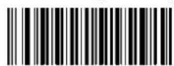
If the Disable 2D Symbologies feature is enabled, the engine will not be able to read any 2D barcodes.
Enable 2D Symbologies
Disable 2D Symbologies
Enter Setup
Exit Setup
3.3 1D
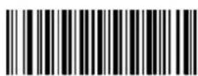
Before starting any symbology setting, please scan "Enter Setup"
Enter Setup
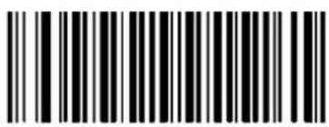
When finished setting, please scan "Exit Setup"
Exit Setup

natural_image
Red curved arrow pointing downward and to the right (no text or symbols)3.3.1 Code 128
Restore the Factory Defaults of Code 128
Enable Code 128*
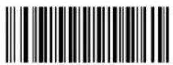
Disable Code 128
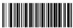
Set the Minimum
Length for Code 128
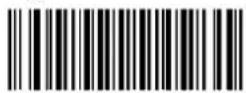
Set the Maximum
Length for Code 128
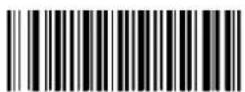
3.3.2 GS1-128 (UCC/EAN-128)
Restore the Factory Defaults of GS1-128
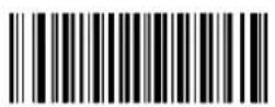
Enable GS1- 128*
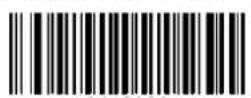
Disable GS1-128
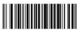
Set the Minimum
Length for GS1-128
Set the Maximum
Length for GS1-128
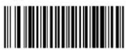
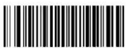
3.3.3 AIM-128
Restore the Factory Defaults of AIM-128
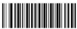
Enable AIM-128*
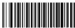
Set the Minimum
Length for AIM-128
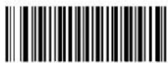
Disable AIM-128
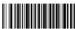
Set the Maximum
Length for AIM-128
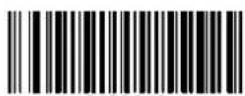
3.3.4 EAN-8
Restore the Factory Defaults of EAN-8
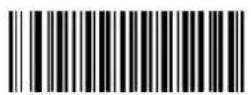
Enable EAN-8*
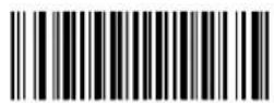
Disable EAN-8
3.3.4.1 Transmit Check Digit
EAN-8 is 8 digits in length with the last one as its check digit used to verify the integrity of the data.
Transmit EAN-8 Check Digit *
Do Not Transmit EAN-8 Check Digit
3.3.4.2 Add-On Code
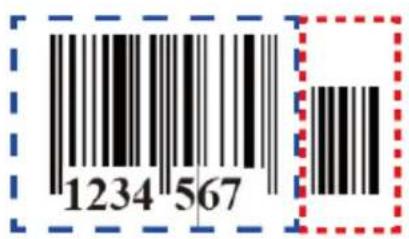
An EAN-8 barcode can be augmented with a two-digit or five-digit add-on code to form a new one. In the examples below, the part surrounded by blue dotted line is an EAN-8 barcode while the part circled by red dotted line is add-on code.
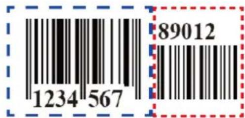
Enter Setup
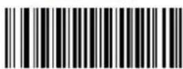
Exit Setup
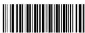
Enable 2-Digit Add-On Code

Enable 5-Digit Add-On Code
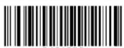
The engine decodes a mix of EAN-8 barcodes with and without 2-digit/5-digit add-on codes.
Disable 2-Digit Add-On Code/ Disable 5-Digit Add-On Code:
The engine decodes EAN-8 and ignores the add-on code when presented with an EAN-8 plus add-on barcode. It can also decode EAN-8 barcodes without add-on codes.
3.3.4.3 Add-On Code Required
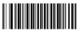
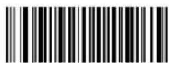
When EAN-8 Add-On Code Required is selected, the engine will only read EAN-8 barcodes that contain add-on codes.
EAN-8 Add-On Code Required
EAN-8 Add-On Code Not Required *
Enter Setup
Exit Setup
3.3.4.4 EAN-8 Extension
Disable EAN-8 Zero Extend: Transmit EAN-8 barcodes as is.
Enable EAN-8 Zero Extend:
Add five leading zeros to decoded EAN-8 barcodes to extend to 13 digits.
Enable EAN-8 Zero Extend
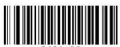
Disable EAN-8 Zero Extend*
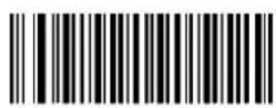
3.3.5 EAN-13
Restore the Factory Defaults of EAN-13
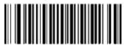
Enable EAN-13*
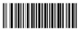
Disable EAN-13
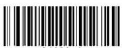
3.3.5.1 Transmit Check Digit
Transmit EAN-13 Check Digit *
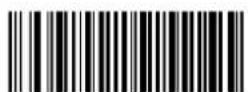
Do Not Transmit EAN-13 Check Digit
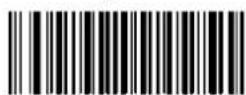
Enter Setup
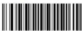
Exit Setup
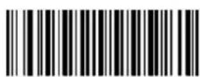
3.3.5.2 Add-On Code
An EAN-13 barcode can be augmented with a two-digit or five-digit add-on code to form a new one.
Enable 2-Digit Add-On Code/ Enable 5-Digit Add-On Code:
The engine decodes a mix of EAN-13 barcodes with and without 2-digit/5-digit add-on codes.
Disable 2-Digit Add-On Code/ Disable 5-Digit Add-On Code:
The engine decodes EAN-13 and ignores the add-on code when presented with an EAN-13 plus add-on barcode. It can also decode EAN-13 barcodes without add-on codes.
Enable 2-Digit Add-On Code
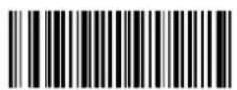
When EAN-13 Add-On Code Required is selected, the engine will only read EAN-13 barcodes that contain add-on codes.
EAN-13 Add-On Code Required
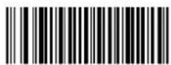
EAN-13 Add-On Code Not Required *
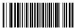
3.3.5.4 EAN-13 Beginning with 290 Add-On Code Required
This setting programs the engine to require an add-on code (2-digit or 5-digit) on EAN-13 barcodes that begin with "290". The following settings can be programmed:
Require Add-On Code: All EAN-13 barcodes that begin with "290" must have a 2-digit or 5-digit add-on code. The EAN-13 barcode with the add-on code is then transmitted. If the required add-on code is not found, the EAN-13 barcode is discarded.
Do Not Require Add-On Code: If you have selected Require Add-On Code, and you want to disable this feature, scan Do Not Require Add-On Code. EAN-13 barcodes are handled, depending on your selection for the "Add-On Code Required" feature.
Do Not Require Add-On Code *
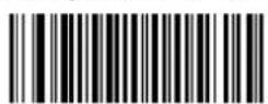
Require Add-On Code
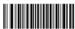
Enter Setup
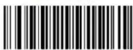
Exit Setup
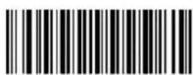
3.3.5.5 EAN-13 Beginning with 378/379 Add-On Code
Required
This setting programs the engine to require an add-on code (2-digit or 5-digit) on EAN-13 barcodes that begin with a "378" or "379". The following settings can be programmed:
Require Add-On Code: All EAN-13 barcodes that begin with a "378" or "379" must have a 2-digit or 5-digit add-on code. The EAN-13 barcode with the add-on code is then transmitted. If the required add-on code is not found, the EAN-13 barcode is discarded.
Do Not Require Add-On Code: If you have selected Require Add-On Code, and you want to disable this feature, scan Do Not Require Add-On Code. EAN-13 barcodes are handled, depending on your selection for the "Add-On Code Required" feature.
Do Not Require Add-On Code *
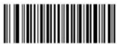
Require Add-On Code
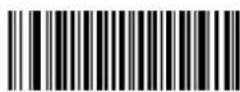
3.3.5.6 EAN-13 Beginning with 414/419 Add-On Code
Required
This setting programs the engine to require an add-on code (2-digit or 5-digit) on EAN-13 barcodes that begin with a "414" or "419".
The following settings can be programmed:
Require Add-On Code: All EAN-13 barcodes that begin with a "414" or "419" must have a 2-digit or 5-digit add-on code. The EAN-13 barcode with the add-on code is then transmitted. If the required add-on code is not found, the EAN-13 barcode is discarded.
Do Not Require Add-On Code: If you have selected Require Add-On Code, and you want to disable this feature, scan Do Not Require Add-On Code. EAN-13 barcodes are handled, depending on your selection for the “Add-On Code Required” feature.
Do Not Require Add-On Code *
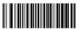
Require Add-On Code
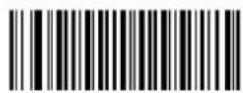
3.3.5.7 EAN-13 Beginning with 434/439 Add-On Code
Required
This setting programs the engine to require an add-on code (2-digit or 5-digit) on EAN-13 barcodes that begin with a "434" or "439". The following settings can be programmed:
Require Add-On Code: All EAN-13 barcodes that begin with a "434" or "439" must have a 2-digit or 5-digit add-on code. The EAN-13 barcode with the add-on code is then transmitted. If the required add-on code is not found, the EAN-13 barcode is discarded.
Do Not Require Add-On Code: If you have selected Require Add-On Code, and you want to disable this feature, scan Do Not Require Add-On Code. EAN-13 barcodes are handled, depending on your selection for the "Add-On Code Required" feature.
Do Not Require Add-On Code *
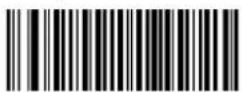
Require Add-On Code
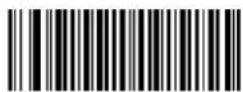
3.3.5.8 EAN-13 Beginning with 977 Add-On Code
Required
This setting programs the engine to require an add-on code (2-digit or 5-digit) on EAN-13 barcodes that begin with "977". The following settings can be programmed:
Require Add-On Code: All EAN-13 barcodes that begin with "977" must have a 2-digit or 5-digit add-on code. The EAN-13 barcode with the add-on code is then transmitted. If the required add-on code is not found, the EAN-13 barcode is discarded.
Do Not Require Add-On Code: If you have selected Require Add-On Code, and you want to disable this feature, scan Do Not Require Add-On Code. EAN-13 barcodes are handled, depending on your selection for the "Add-On Code Required" feature.
Do Not Require Add-On Code *

Require Add-On Code
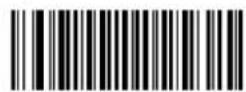
3.3.5.9 EAN-13 Beginning with 978 Add-On Code
Required
This setting programs the engine to require an add-on code (2-digit or 5-digit) on EAN-13 barcodes that begin with "978". The following settings can be programmed:
Require Add-On Code: All EAN-13 barcodes that begin with "978" must have a 2-digit or 5-digit add-on code. The EAN-13 barcode with the add-on code is then transmitted. If the required add-on code is not found, the EAN-13 barcode is discarded.
Do Not Require Add-On Code: If you have selected Require Add-On Code, and you want to disable this feature, scan Do Not Require Add-On Code. EAN-13 barcodes are handled, depending on your selection for the "Add-On Code Required" feature.
Do Not Require Add-On Code *
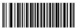
Require Add-On Code
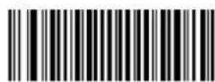
3.3.5.10 EAN-13 Beginning with 979 Add-On Code
Required
This setting programs the engine to require an add-on code (2-digit or 5-digit) on EAN-13 barcodes that begin with "979". The following settings can be programmed:
Require Add-On Code: All EAN-13 barcodes that begin with "979" must have a 2-digit or 5-digit add-on code. The EAN-13 barcode with the add-on code is then transmitted. If the required add-on code is not found, the EAN-13 barcode is discarded.
Do Not Require Add-On Code: If you have selected Require Add-On Code, and you want to disable this feature, scan Do Not Require Add-On Code. EAN-13 barcodes are handled, depending on your selection for the "Add-On Code Required" feature.
Do Not Require Add-On Code *
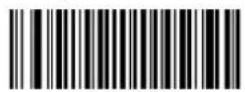
Require Add-On Code
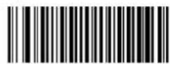
3.3.6 ISSN
Restore the Factory Defaults of ISSN
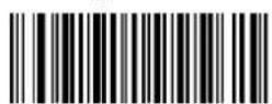
Enable ISSN
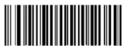
Disable ISSN*
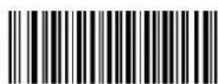
Enter Setup
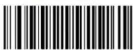
Exit Setup
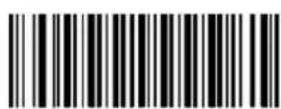
3.3.6.1 Add-On Code
An ISSN barcode can be augmented with a two-digit or five-digit add-on code to form a new one.
Enable 2-Digit Add-On Code/ Enable 5-Digit Add-On Code:
The engine decodes a mix of ISSN barcodes with and without 2-digit/5-digit add-on codes.
Disable 2-Digit Add-On Code/ Disable 5-Digit Add-On Code:
The engine decodes ISSN and ignores the add-on code when presented with an ISSN plus add-on barcode. It can also decode ISSN barcodes without add-on codes.
Enable 2-Digit Add-On Code
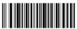
When ISSN Add-On Code Required is selected, the engine will only read ISSN barcodes that contain add-on codes.
ISSN Add-On Code Required
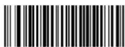
ISSN Add-On Code Not Required *

Enter Setup
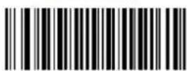
Exit Setup
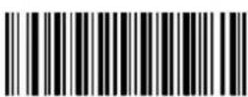
3.3.7 ISBN
Restore the Factory Defaults of ISBN
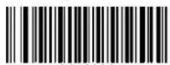
Enable ISBN *
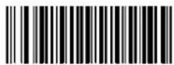
Disable ISBN
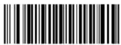
3.3.7.1 Set ISBN Format
ISBN-13*
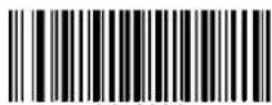
ISBN-10
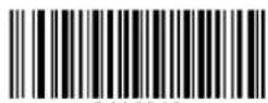
Enter Setup
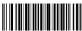
Exit Setup
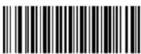
3.3.7.2 Add-On Code
An ISBN barcode can be augmented with a two-digit or five-digit add-on code to form a new one.
Enable 2-Digit Add-On Code/ Enable 5-Digit Add-On Code:
The engine decodes a mix of ISBN barcodes with and without 2-digit/5-digit add-on codes.
Disable 2-Digit Add-On Code/ Disable 5-Digit Add-On Code:
The engine decodes ISBN and ignores the add-on code when presented with an ISBN plus add-on barcode. It can also decode ISBN barcodes without add-on codes.
Enable 2-Digit Add-On Code
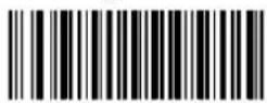
A UPC-E barcode can be augmented with a two-digit or five-digit add-on code to form a new one.
Enable 2-Digit Add-On Code/ Enable 5-Digit Add-On Code:
The engine decodes a mix of UPC-E barcodes with and without 2-digit/5-digit add-on codes.
Disable 2-Digit Add-On Code/ Disable 5-Digit Add-On Code:
The engine decodes UPC-E and ignores the add-on code when presented with an UPC-E plus add-on barcode. It can also decode UPC-E barcodes without add-on codes.
Enable 2-Digit Add-On Code
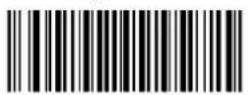
3.3.8.4 Transmit System Character "0"
The first character of UPC-E barcode is the system character "0".
Transmit System Character "0" *
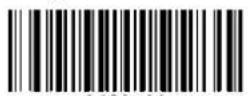
Do Not Transmit System Character "0"
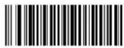
3.3.8.5 UPC-E Extension
Disable UPC-E Extend: Transmit UPC-E barcodes as is.
Enable UPC-E Extend: Extend UPC-E barcodes to make them compatible in length to UPC-A.
Enable UPC-E Extend
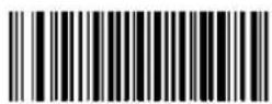
Disable UPC-E Extend *
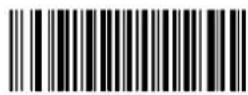
3.3.9 UPC-A
Restore the Factory Defaults of UPC-A
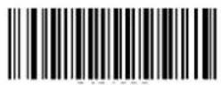
Enable UPC-A *
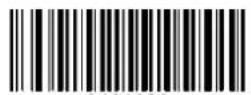
Disable UPC-A
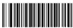
3.3.9.1 Transmit Check Digit
Transmit UPC-A Check Digit *
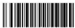
Do Not Transmit UPC-A Check Digit
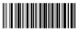
3.3.9.2 Add-On Code
A UPC-A barcode can be augmented with a two-digit or five-digit add-on code to form a new one.
Enable 2-Digit Add-On Code/ Enable 5-Digit Add-On Code:
The engine decodes a mix of UPC-A barcodes with and without 2-digit/5-digit add-on codes.
Disable 2-Digit Add-On Code/ Disable 5-Digit Add-On Code:
The engine decodes UPC-A and ignores the add-on code when presented with an UPC-A plus add-on barcode. It can also decode UPC-A barcodes without add-on codes.
Enable 2-Digit Add-On Code
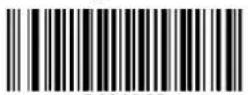
When UPC-A Add-On Code Required is selected, the engine will only read UPC-A barcodes that contain add-on codes.
UPC-A Add-On Code Required
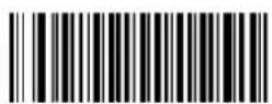
UPC-A Add-On Code Not Required *
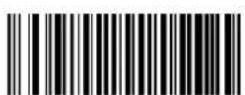
Enter Setup
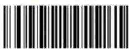
Exit Setup
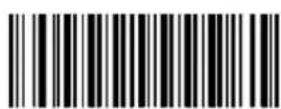
3.3.9.4 Transmit Preamble Character
Preamble characters (Country Code and System Character) can be transmitted as part of a UPC-A barcode. Select one of the following options for transmitting UPC-A preamble to the host device: transmit system character only, or transmit system character and country code ("0" for USA), or transmit no preamble.
System Character & Country Code
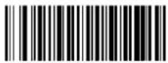
System Character *
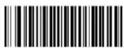
No Preamble
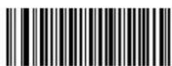
3.3.10 Interleaved 2 of 5
Restore the Factory Defaults of Interleaved 2 of 5
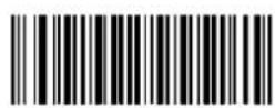
Enable Interleaved 2 of 5 *
Disable Interleaved 2 of 5
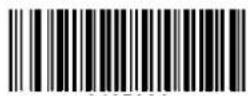
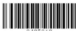
Set the Minimum Length for Interleaved 2 of 5
Set the Maximum Length for Interleaved 2 of 5
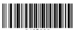
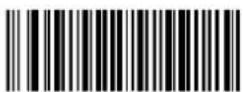
3.3.10.1 Check Digit Verification
A check digit is optional for Interleaved 2 of 5 and can be added as the last digit. It is a calculated value used to verify the integrity of the data.
Disable: The engine transmits Interleaved 2 of 5 barcodes as is.
Do Not Transmit Check Digit After Verification:
The engine checks the integrity of all Interleaved 2 of 5 barcodes to verify that the data complies with the check digit algorithm. Barcodes passing the check will be transmitted except the last digit, whereas those failing it will not be transmitted.
Transmit Check Digit After Verification:
The engine checks the integrity of all Interleaved 2 of 5 barcodes to verify that the data complies with the check digit algorithm. Barcodes passing the check will be transmitted, whereas those failing it will not be transmitted.
Disable*
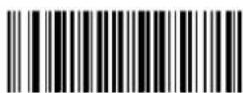
Do Not Transmit Check Digit After Verification
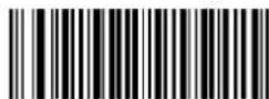
Transmit Check Digit After Verification
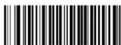
Note: If the Do Not Transmit Check Digit After Verification option is enabled, Interleaved 2 of 5 barcodes with a length that is less than the configured minimum length after having the check digit excluded will not be decoded. (For example, when the Do Not Transmit Check Digit After Verification option is enabled and the minimum length is set to 4, Interleaved 2 of 5 barcodes with a total length of 4 characters including the check digit cannot be read.)
3.3.10.2 ITF-14
ITF-14 is a special kind of Interleaved 2 of 5 with a length of 14 characters and the last character as the check character.
Restore the Factory Defaults of ITF-14
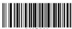
Disable ITF-14
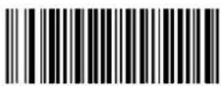
Enable ITF-14 But Do Not Transmit Check Digit *
Enable ITF-14 and Transmit Check Digit
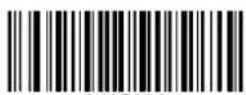
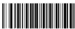
Note: It is advisable not to enable ITF-14 and Interleaved 2 of 5 at the same time.
3.3.10.3 ITF-6
ITF-6 is a special kind of Interleaved 2 of 5 with a length of 6 characters and the last character as the check character.
Restore the Factory Defaults of ITF-6
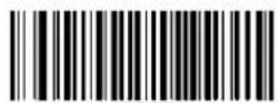
Disable ITF-6 *
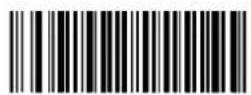
Enable ITF-6 But Do Not Transmit Check Digit
Enable ITF-6 and Transmit Check Digit
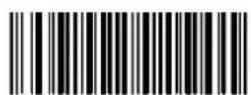
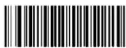
Note: It is advisable not to enable ITF-6 and Interleaved 2 of 5 at the same time.
3.3.11 Matrix 2 of 5
Restore the Factory Defaults of Matrix 2 of 5
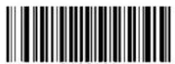
Enable Matrix 2 of 5
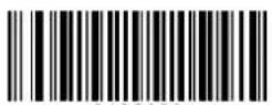
Disable Matrix 2 of 5 *
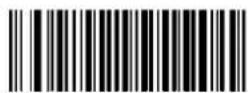
Set the Minimum Length
for Matrix 2 of 5
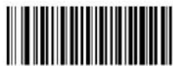
Set the Maximum Length
for Matrix 2 of 5
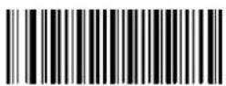
3.3.11.1 Check Digit Verification
Do Not Transmit Check Digit After
Verification *
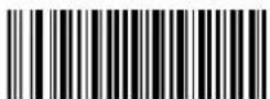
Transmit Check Digit After Verification
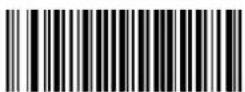
Disable
Enter Setup
Exit Setup
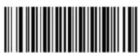
3.3.12 Industrial 2 of 5
Restore the Factory Defaults of Industrial 2 of 5
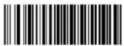
Enable Industrial 2 of 5 *
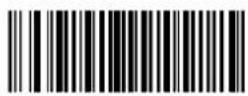
Disable Industrial 2 of 5
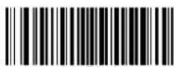
Set the Minimum Length for Industrial 2 of 5
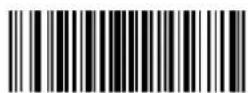
Set the Maximum Length for Industrial 2 of 5
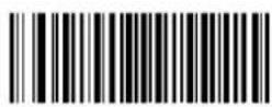
3.3.12.1 Check Digit Verification
Do Not Transmit Check Digit After Verification
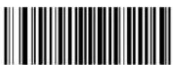
Transmit Check Digit After Verification
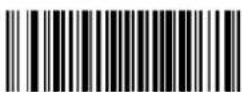
Disable *
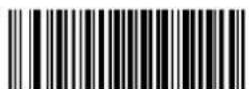
Enter Setup
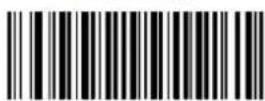
Exit Setup
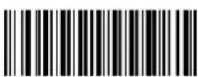
3.3.13 Standard 2 of 5 (IATA 2 of 5)
Restore the Factory Defaults of Standard 25
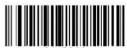
Enable Standard 25 *
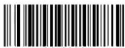
Disable Standard 25
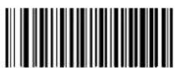
Set the Minimum Length for Standard 25
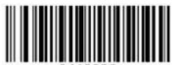
Set the Maximum Length for Standard 25
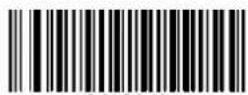
3.3.13.1 Check Digit Verification
Do Not Transmit Check Digit After
Verification
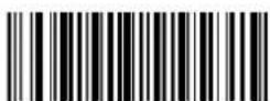
Transmit Check Digit After Verification
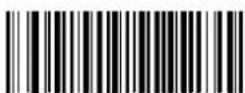
Disable *
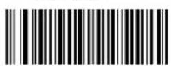
Enter Setup
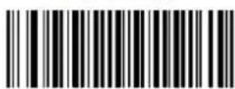
Exit Setup
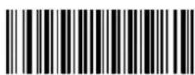
3.3.14 Code 39
Restore the Factory Defaults of Code 39
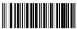
Enable Code 39 *
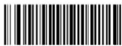
Disable Code 39
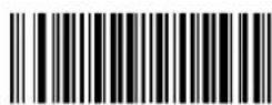
Do Not Transmit Start/Stop Character *
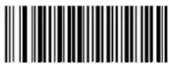
Transmit Start/Stop Character
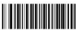
Set the Minimum Length for Code 39
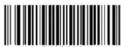
Set the Maximum Length for Code 39
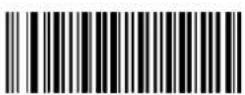
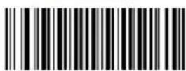
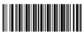
3.3.14.1 Check Digit Verification
Do Not Transmit Check Digit After Verification
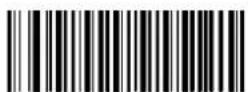
Transmit Check Digit After Verification
Enter Setup
Exit Setup
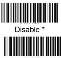
3.3.14.2 Enable/Disable Code 39 Full ASCII
The engine can be configured to identify all ASCII characters by scanning the appropriate barcode below.
Enable Code 39 Full ASCII *
Disable Code 39 Full ASCII
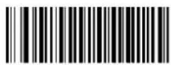
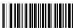
3.3.15 Code 32
Code 32 is a variant of Code 39 used by the Italian pharmaceutical industry. Scan the appropriate bar code below to enable or disable Code 32. Code 39 must be enabled and Code 39 check digit verification must be disabled for this parameter to function.
Disable Code 32 *
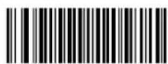
Enable Code 32
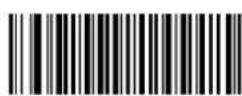
3.3.15.1 Code 32 Prefix
Scan the appropriate bar code below to enable or disable adding the prefix
Enter Setup
Exit Setup
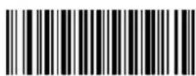
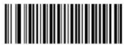
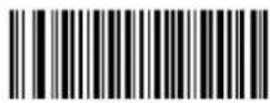
character "A" to all Code 32 barcodes. Code 32 must be enabled for this parameter to function.
Disable Code 32 Prefix * Enable Code 32 Prefix
3.3.15.2 Transmit Code 32 Check Digit
Code 32 must be enabled for this parameter to function.
Do Not Transmit Code 32 Check Digit *
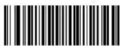
Transmit Code 32 Check Digit
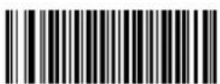
3.3.15.3 Transmit Code 32 Start/Stop Character
Code 32 must be enabled for this parameter to function.
Do Not Transmit Code 32 Start/Stop Character *
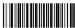
Transmit Code 32 Start/Stop Character
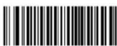
Enter Setup
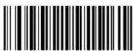
Exit Setup
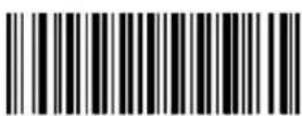
3.3.16 Codabar
Restore the Factory Defaults of Codabar
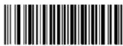
Enable Codabar *
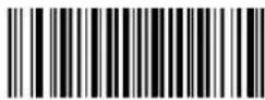
Disable Codabar
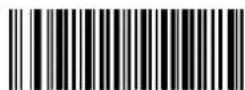
Set the Minimum Length for Codabar
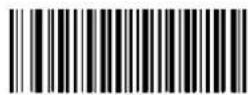
Set the Maximum Length for Codabar
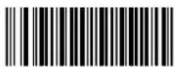
3.3.16.1 Check Digit Verification
Disable *
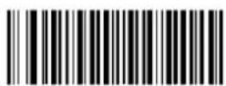
Transmit Check Digit After Verification
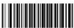
Do Not Transmit Check Digit After Verification
Enter Setup
Exit Setup
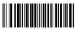
3.3.16.2 Transmit Start/Stop Character
Do not Transmit Start/Stop Character *
Transmit Start/Stop Character
3.3.16.3 Start/Stop Character Format
You can choose your desired start/stop character format by scanning the appropriate barcode below.
ABCD/ABCD as the Start/Stop Character *
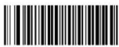
ABCD/TN*E as the Start/Stop Character
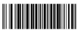
Start/Stop Character in Uppercase
Start/Stop Character in Lowercase
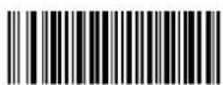
Enter Setup
Exit Setup
3.3.17 Code 93
Restore the Factory Defaults of Code 93
Enable Code 93 *
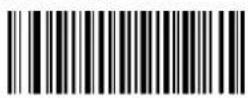
Disable Code 93
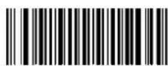
Set the Minimum Length
for Code 93
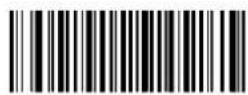
Set the Maximum Length
for Code 93
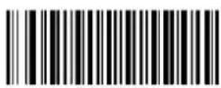
3.3.17.1 Check Digit Verification
Disable
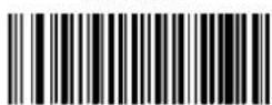
Transmit Check Digit After
Verification
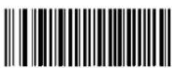
Do Not Transmit Check Digit After
Verification *
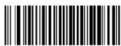
Enter Setup
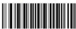
Exit Setup
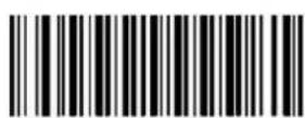
3.3.18 GS1-Databar (RSS)
Restore the Factory Defaults of GS1-Databar
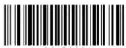
Enable GS1-Databar *
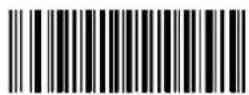
Disable GS1-Databar
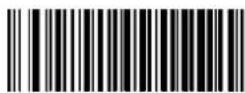
3.3.18.1 Transmit Application Identifier "01"
Transmit Application Identifier "01" *
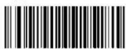
Do Not Transmit Application Identifier "01"
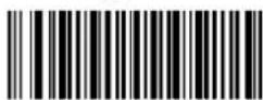
3.3.19 Code 11
Restore the Factory Defaults of Code 11
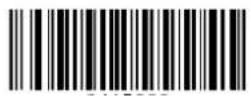
Enable Code 11 *
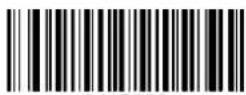
Disable Code 11
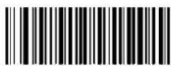
Set the Minimum Length for Code 11
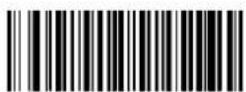
Set the Maximum Length for Code 11
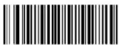
3.3.19.1 Transmit Check Digit
Transmit Check Digit
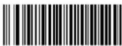
Do Not Transmit Check Digit *
Enter Setup
Exit Setup
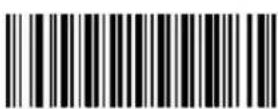
3.3.19.2 Check Digit Verification
Disable
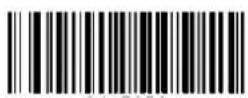
Two Check Digits, MOD11/MOD11
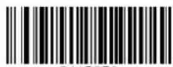
One Check Digit, MOD11
(Len<=10)
Two Check Digits, MOD11/MOD11 (Len>10)
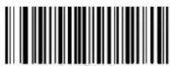
One Check Digit, MOD11 *
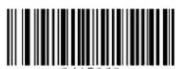
Two Check Digits, MOD11/MOD9
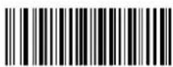
One Check Digit, MOD11
(Len<=10)
Two Check Digits, MOD11/MOD9 (Len>10)
Enter Setup
Exit Setup
3.3.20 Plessey
Restore the Factory Defaults of Plessey
Enable Plessey *
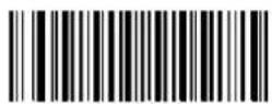
Disable Plessey
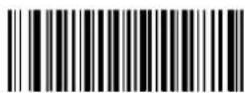
Set the Minimum Length for Plessey
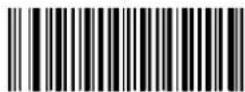
Set the Maximum Length for Plessey
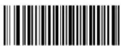
3.3.20.1 Check Digit Verification
Do Not Transmit Check Digit After Verification *
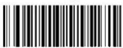
Transmit Check Digit After Verification
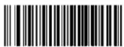
Disable
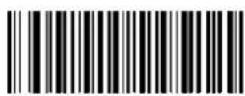
Enter Setup
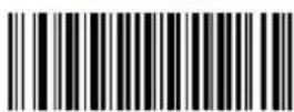
Exit Setup
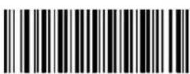
3.3.21 MSI-Plessey
Restore the Factory Defaults of MSI-Plessey
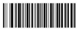
Enable MSI-Plessey *
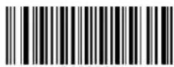
Disable MSI-Plessey
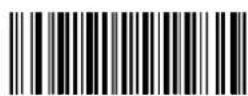
Set the Minimum Length for MSI-Plessey
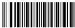
Set the Maximum Length for MSI-Plessey
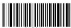
3.3.21.1 Transmit Check Digit
Transmit Check Digit
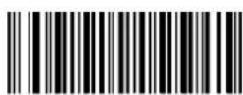
Do Not Transmit Check Digit *
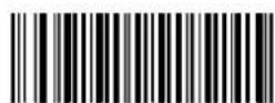
Enter Setup
Exit Setup
3.3.21.2 Check Digit Verification
One Check Digit, MOD10 *
Two Check Digits, MOD10/MOD10
Disable
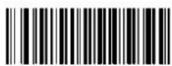
Two Check Digits, MOD10/MOD11
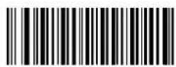
3.3.22 JAN
3.3.22.1 JAN Code for Magazines
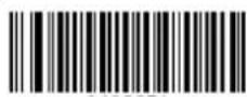
Japanese Article Number (JAN) is a barcode standard compatible with the EAN. JAN barcodes for magazines are EAN-13 barcodes starting with a "491" and containing a 5-digit add-on code. Scan the appropriate barcode below to enable or disable JAN barcodes for magazines.
Enable JAN Code for Magazines
Disable JAN Code for Magazines *
3.3.22.2 JAN Code for Books
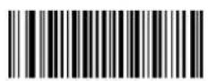
JAN barcodes for books include an ISBN barcode starting with a "978" and an EAN-13 barcodes starting with a "191" or "192". When left on the default setting (Disable JAN Code for Books), the engine treats the ISBN and EAN-13 barcodes as single barcodes.
When enabled, the engine must see and read the ISBN and EAN-13 barcodes in a single read to transmit the data. No data is output unless both barcodes are read.
Enable JAN Code for Books
Disable JAN Code for Books *
You may select either of the following ways to transmit JAN barcodes for books.
Enter Setup
Exit Setup
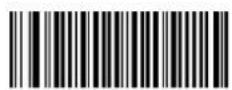
If you scan the Do Not Require Concatenation barcode, the engine transmits the ISBN and EAN-13 barcodes as separate symbologies.
If you scan the Require Concatenation barcode, the engine transmits the ISBN and EAN-13 barcodes as an ISBN barcode.
Require Concatenation
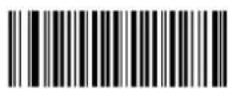
Do Not Require
Concatenation *
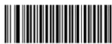
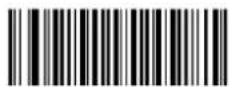
A separator (a comma “,”) can be inserted between the ISBN and EAN-13 barcodes. Note that the Require Concatenation feature must be enabled for this setting to function.
Enable Barcode
Separator
Disable Barcode
Separator *
3.4 2D
3.4.1 PDF 417
Restore the Factory Defaults of PDF 417
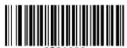
Enable PDF 417 *
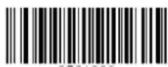
Disable PDF 417
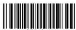
Set the Minimum Length for PDF 417
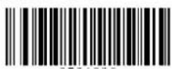
Set the Maximum Length for PDF 417
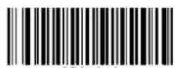
PDF417 twin code is 2 PDF417 barcodes paralleled vertically or horizontally. They must both be either regular or inverse barcodes. They must have similar specifications and be placed closely together.
There are 3 options for reading PDF417 twin codes:
Single PDF417 Only: Read either PDF417 code.
Twin PDF417 Only: Read both PDF417 codes.
Both Single & Twin: Read both PDF417 codes. If successful, transmit as twin PDF417 only. Otherwise, try single PDF417 only.
Single PDF417 Only
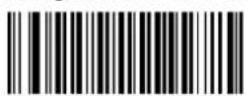
Twin PDF417 Only
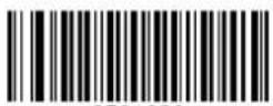
Both Single & Twin
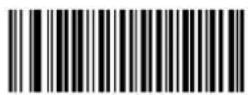
3.4.1.2 Character Encoding
Default Character
Encoding *
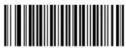
UTF-8
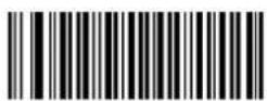
3.4.1.3 Enable/Disable PDF417 ECI Output
Disable PDF417 ECI
Output
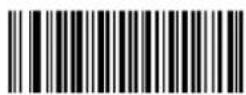
Enable PDF417 ECI
Output *
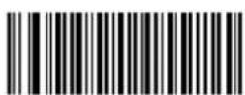
Enter Setup
Exit Setup
3.4.2 QR Code
Restore the Factory Defaults of QR Code
Enable QR Code *
Disable QR Code
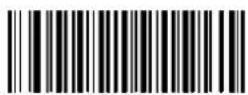
Set the Minimum Length for QR Code
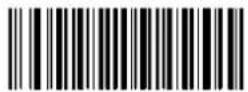
Set the Maximum Length for QR Code
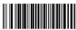
3.4.2.1 Micro QR
Disable Micro QR *
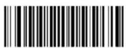
Enable Micro QR
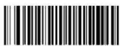
Enter Setup
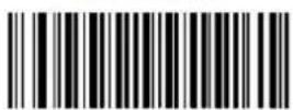
Exit Setup
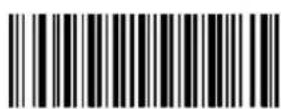
QR twin code is 2 QR barcodes paralleled vertically or horizontally. They must both be either regular or inverse barcodes. They must have similar specifications and be placed closely together.
There are 3 options for reading QR twin codes:
Single QR Only: Read either QR code.
Twin QR Only: Read both QR codes.
Both Single & Twin: Read both QR codes. If successful, transmit as twin QR only. Otherwise, try single QR only.
Single QR Only *
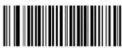
Twin QR Only
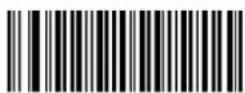
Both Single & Twin
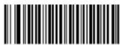
3.4.2.3 Character Encoding
Default Character
Encoding *
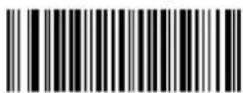
UTF-8
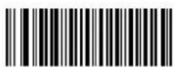
3.4.2.4 Enable/Disable QR ECI Output
Enable QR ECI Output *
Disable QR ECI Output
Enter Setup
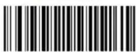
Exit Setup
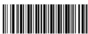

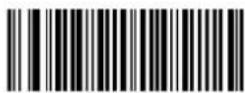
Enter Setup
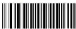
Exit Setup
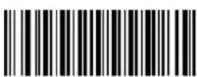
3.4.3 Data Matrix
Restore the Factory Defaults of Data Matrix
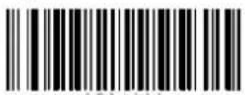
Enable Data Matrix *
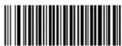
Disable Data Matrix
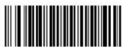
Set the Minimum Length for Data Matrix
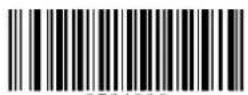
Set the Maximum Length for Data Matrix
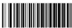
3.4.3.1 Rectangular Barcode
Enable Rectangular Barcode *
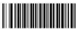
Disable Rectangular Barcode
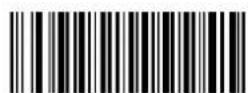
Data Matrix twin code is 2 Data Matrix barcodes paralleled vertically or horizontally. They must both be either regular or inverse barcodes. They must have similar specifications and be placed closely together.
There are 3 options for reading Data Matrix twin codes:
Single Data Matrix Only: Read either Data Matrix code.
Twin Data Matrix Only: Read both Data Matrix codes. Transmission order: Data Matrix code on the left (in the upper position) followed by the one on the right (in the lower position).
Both Single & Twin: Read both Data Matrix codes. If successful, transmit as twin Data Matrix only. Otherwise, try single Data Matrix only.
Single Data Matrix Only *
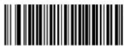
Twin Data Matrix Only
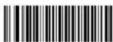
Both Single & Twin
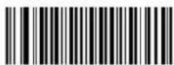
3.4.3.4 Character Encoding
Default Character Encoding *
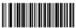
UTF-8
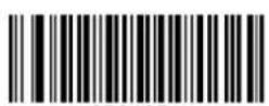
3.4.3.5 Enable/Disable Data Matrix ECI Output
Enable Data Matrix ECI Output *
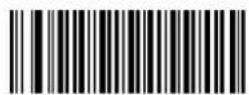
Disable Data Matrix ECI Output
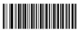
3.4.4 Chinese Sensible Code
Restore the Factory Defaults of Data Matrix
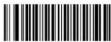
Disable Chinese
Sensible Code *
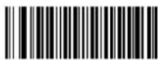
Enable Chinese Sensible
Code
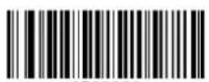
Set the Minimum Length
for Chinese Sensible
Code
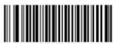
Set the Maximum Length
for Chinese Sensible
Code
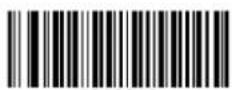
3.4.4.1 Enable/Disable Chinese Sensible Code ECI
Output
Enable Chinese Sensible Code ECI
Output *
Disable Chinese Sensible Code
ECI Output
Enter Setup
Exit Setup
Chapter 4 - Command Settings
4.1 Operation Mode
4.1.1 Auto
Scan below bar code for auto mode setting

4.1.2 Batch
Scan below bar code for batch mode setting
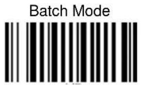
4.1.3 Wedge
Scan below bar code for wedge mode setting
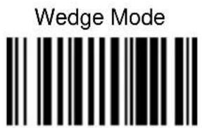
4.2 System setting
4.2.1 Default
Scan below bar code to restore the factory setting
Factory Default
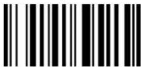
4.2.2 Display FW version / Data Format
Scan below bar code to show the current F/W & BT version
FW version
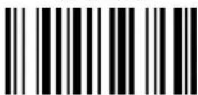
4.2.3 Auto Power Off
Scan below bar code to set the time frame for auto power off
1 Minute
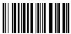
10 Minutes
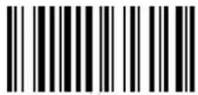
30 Minutes
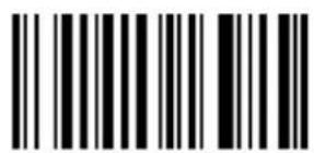
3 Minutes
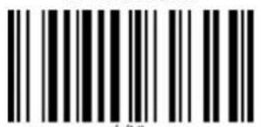
15 Minutes
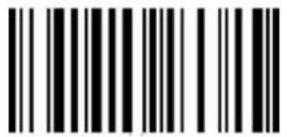
5 Minutes *
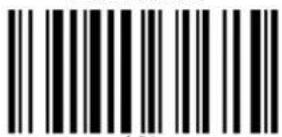
20 Minutes
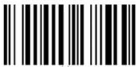
Disable
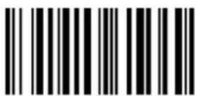
4.2.4 Power Saving
Scan below bar code to set the time frame for power saving.
5 Seconds
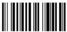
20 Seconds
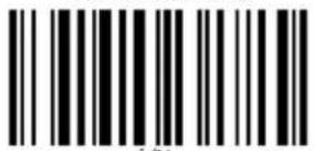
10 Seconds
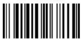
30 Seconds
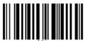
15 Seconds*
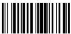
60 Seconds
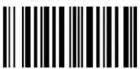
Note:
Strongly recommend not to disable the power saving setting.
The device might experience the screen burn-in (an after-image effect) on the OLED screen if the screen is on for the long hours.
Enter Setup
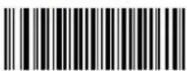
Exit Setup
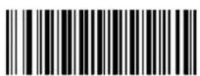
4.3 RF Config.
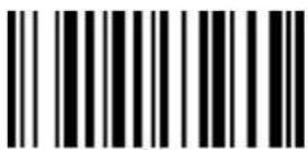
4.3.1 Paired device info.
Scan below bar code to show the current paired device information
Paired Device
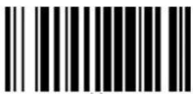
4.3.2 Remove the pair
Scan below bar code to remove pair
Remove Pair
4.4 Data & Memory
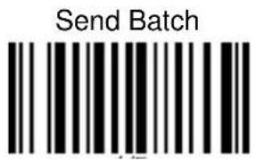
4.4.1 Send Batch
Scan【Batch】to switch from Auto Mode to Batch Mode. Data will now be stored in the internal memory of the MS926P and the MS926P will no longer transmit data via RF. Scan below barcode to send data from the MS926P to your host device after collecting the data in Batch Mode. Scan【Auto】to switch back to Auto Mode.
4.4.1.1 Erase last memory entry
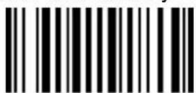
Scan below bar code to erase last scanned data in memory
Erased Last Memory Entry
4.4.1.2 Erase all data in buffer (Erase Memory)
Scan below bar code to erase all data in the memory
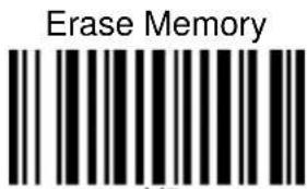
4.4.1.3 Check buffer memory space
Scan below bar code to check buffer memory space
Free Memory Space
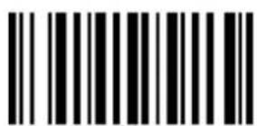
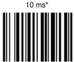
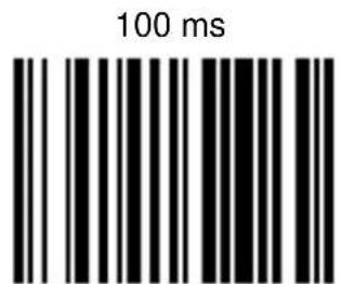
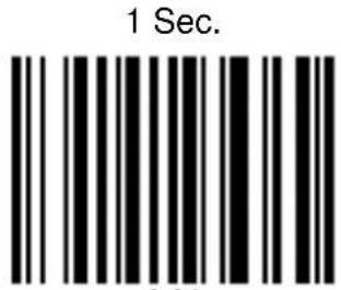
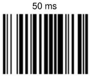
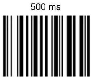
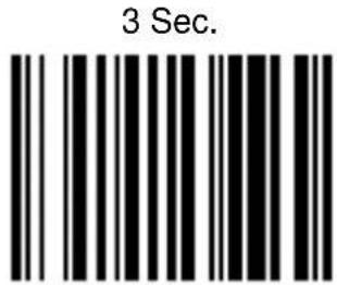
4.5 Data Sending Block Delay
Scan below bar code to set the block delay time. Default is 10ms.
Enter Setup
Exit Setup
4.6 HID Keyboard Character Delay
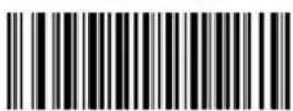
Scan below bar code to set HID keyboard character delay time. Default is 1ms.
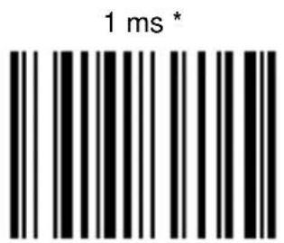
10 ms
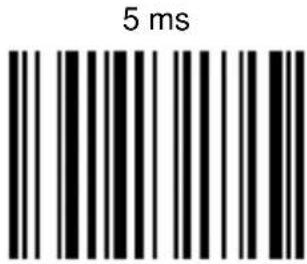
20 ms
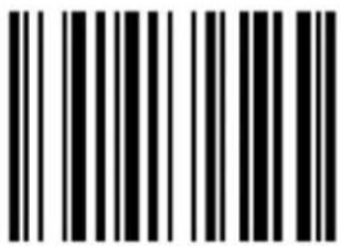
50 ms
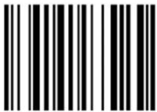
100 ms
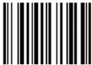
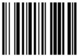
Enter Setup
Exit Setup
4.6.1 HID keyboard Case
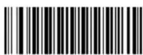
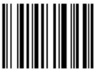
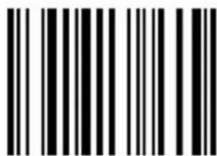
Scan below bar code to change the alphabet case. Scan "to lower" barcode to output data in lower case; or scan "to upper" barcode to output data in upper case. Default setting: "auto trace" to have original scanned data transmitted.
Auto Trace *
To Lower
To Upper
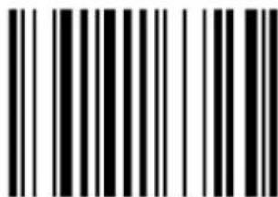
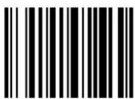
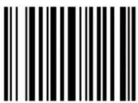
4.6.2 HID keyboard language
Scan below bar code to change keyboard language. Default is US English
US English *
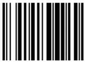
Swedish
UK English
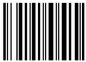
Norwegian
Swiss
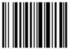
Italian
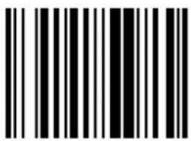
German
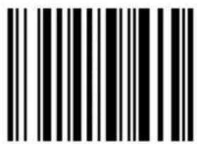
French
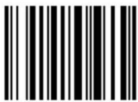
Danish
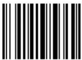
Partial ALT
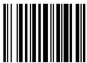
Japanese (OADG109)
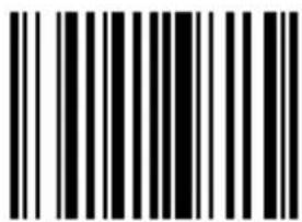
Spanish
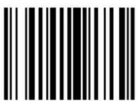
ALT Mode
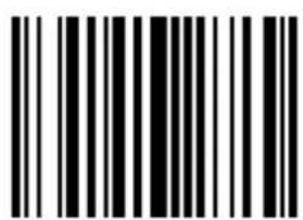
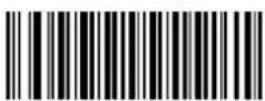
Enter Setup
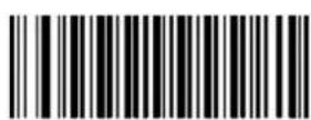
Exit Setup
4.7 Beep & Vibration & Indicators
4.7.1 Beep Control
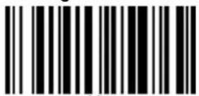
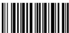
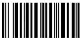
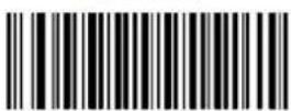
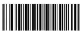
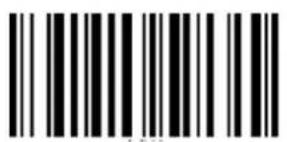
Scan below bar code to adjust beep volume. Default: Medium volume
4.7.1.1 High volume
High Volume
4.7.1.2 Medium volume \*
Medium Volume*
4.7.1.3 Low volume
Low Volume
4.7.1.4 Mute
Mute
Enter Setup
Exit Setup
4.7.2 Vibration
The vibration is off in default. Scan below bar code to open vibration function
Enable Vibrator
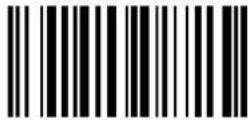
Disable Vibrator *

4.7.3 Beep & Vibration Setting manually
Please follow the steps to set up the Beep & Vibration.
- Main Menu → Beep & Vibrate → Indicators → Button
Beeper & Vibrator * None Beeper Vibrator
4.7.4 Indicators
4.7.4.1 Good Read Indicator
Beeper
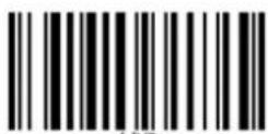
Beeper & Vibrator *
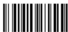
Vibrator
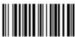
None
Enter Setup
Exit Setup
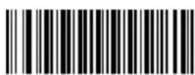
4.7.4.2 Button Indicator
Beeper
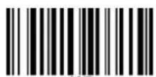
Beeper & Vibrator *
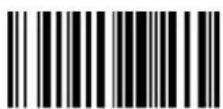
Vibrator
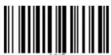
None
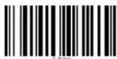
4.7.4.3 System Setting Indicator
Beeper *
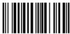
Beeper & Vibrator
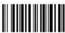
Vibrator
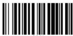
None
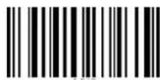
4.7.4.4 System Warning/Error Indicator
Beeper *
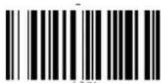
Beeper & Vibrator
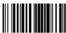
Vibrator
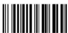
None
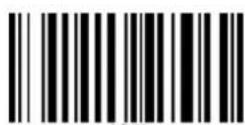
4.7.4.5 Power On Indicator
Beeper
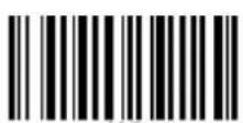
Beeper & Vibrator *
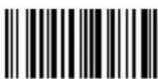
Vibrator
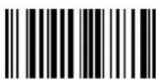
None
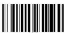
4.7.4.6 Power Off Alarm
Enter Setup
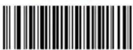
Exit Setup
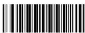
Beeper
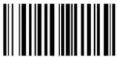
Beeper & Vibrator *
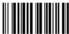
Vibrator
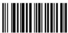
None
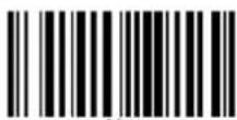
Enter Setup
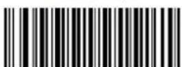
Exit Setup
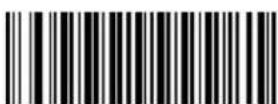
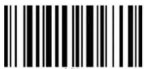
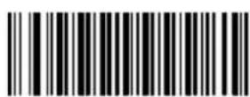
4.8 Data Terminator
Scan below bar code to set up terminator.
None
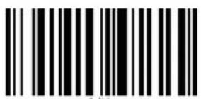
CR*
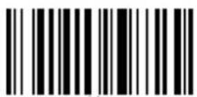
CRLF
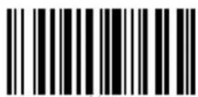
LF
TAB
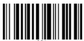
Enter Setup
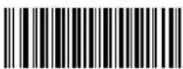
Exit Setup
4.9 1:1 / 1:N Checking Indicators
4.9.1 1:1/1:N Checking Pass Indicator
Scan below bar code toindicate 1:1/1:N Checking Pass.
None
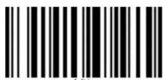
Vibrator
Beeper & Vibrator *
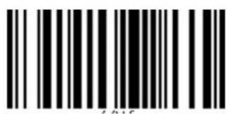
Beeper
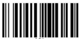
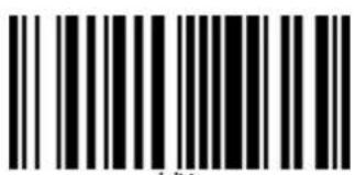
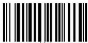
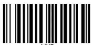
4.9.2 1:1/1:N Checking Fail Indicator
Scan below bar code to indicate 1:1/1:N Checking Fail.
None
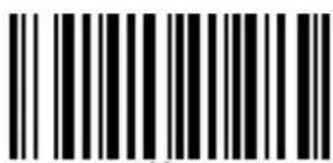
Vibrator
Beeper & Vibrator *
Beeper
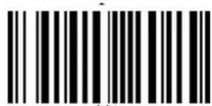
Enter Setup
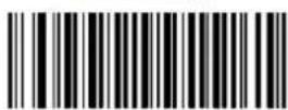
Exit Setup
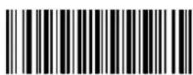
4.9.3 Pause Scan When 1:1/1:N Checking Fail
Scan below bar code to indicate pause scan when 1:1/1:N Checking Fail.
Enable
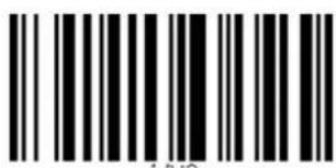
Disable *
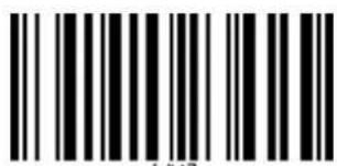
4.9.4 1:1/1:N Checking Screen Indicator
Scan below bar code to indicate 1:1/1:N Screen Checking.
Enable
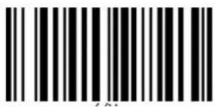
Disable *
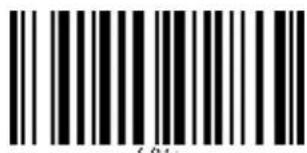
Enter Setup
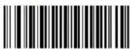
Exit Setup
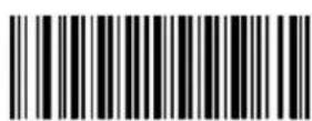
Appendix A - Parameter
Programming Examples
The following examples show you how to program parameters by scanning programming barcodes.
a. Program the Decode Session Timeout
Example: Set the decode session timeout to 1500ms
- Scan the Enter Setup barcode.
- Scan the Decode Session Timeout barcode.
- Scan the numeric barcodes "1", "5", "0" and "0".
- Scan the Save barcode.
- Scan the Exit Setup barcode.
(If you still need to program other parameter/feature, skip this step.)
b. Program the Idle Timeout
Example: Set the idle timeout to 500ms
- Scan the Enter Setup barcode.
- Scan the Idle Timeout barcode.
- Scan the numeric barcodes "5", "0" and "0".
- Scan the Save barcode.
- Scan the Exit Setup barcode.
(If you still need to program other parameter/feature, skip this step.)
c. Program the Image Stabilization Timeout
Example: Set the image stabilization timeout to 500ms
- Scan the Enter Setup barcode.
- Scan the Image Stabilization Timeout barcode.
- Scan the numeric barcodes "5", "0" and "0".
- Scan the Save barcode.
- Scan the Exit Setup barcode.
(If you still need to program other parameter/feature, skip this step.)
d. Program the Timeout between Decodes (Same Barcode)
Example: Set the timeout between decodes (same barcode) to 1000ms
- Scan the Enter Setup barcode.
- Scan the Timeout between Decodes (Same Barcode) barcode.
- Scan the numeric barcodes "1", "0", "0" and "0".
- Scan the Save barcode.
- Scan the Exit Setup barcode.
(If you still need to program other parameter/feature, skip this step.)
e. Program the Threshold Value of Illumination Change
Example: Set the threshold value of illumination change to 4
- Scan the Enter Setup barcode.
- Scan the Threshold Value of Illumination Change barcode.
- Scan the numeric barcode "4".
- Scan the Save barcode.
- Scan the Exit Setup barcode.
(If you still need to program other parameter/feature, skip this step.)
f. Program the Timeout between Decodes
Example: Set the timeout between decodes to 500ms
- Scan the Enter Setup barcode.
- Scan the Timeout between Decodes barcode.
- Scan the numeric barcodes "5", "0" and "0".
- Scan the Save barcode.
- Scan the Exit Setup barcode.
(If you still need to program other parameter/feature, skip this step.)
g. Program the Decoding Area
Example: Set the decoding area to 20% top, 80% bottom, 20% left and 80% right.
- Scan the Enter Setup barcode.
- Scan the Specific Area Decoding barcode.
- Scan the Top of Decoding Area barcode.
- Scan the numeric barcodes "2" and "0".
- Scan the Save barcode.
- Scan the Bottom of Decoding Area barcode.
- Scan the numeric barcodes "8" and "0".
- Scan the Save barcode.
-
Scan the Left of Decoding Area barcode.
-
Scan the numeric barcodes "2" and "0".
-
Scan the Save barcode.
-
Scan the Right of Decoding Area barcode.
-
Scan the numeric barcodes "8" and "0".
-
Scan the Save barcode.
-
Scan the Exit Setup barcode.
(If you still need to program other parameter/feature, skip this step.)
h. Program the Custom Prefix/Suffix
Example: Set the custom prefix to "CODE"
- Check the hex values of "CODE" in the ASCII Table.
("CODE": 43, 4F, 44, 45) - Scan the Enter Setup barcode.
- Scan the Set Custom Prefix barcode.
- Scan the numeric barcodes "4", "3", "4", "F", "4", "4", "4" and "5".
- Scan the Save barcode.
- Scan the Exit Setup barcode.
(If you still need to program other parameter/feature, skip this step.)
i. Program the Terminating Character Suffix
Example: Set the terminating character suffix to 0x0D
- Scan the Enter Setup barcode.
- Scan the Set Terminating Character Suffix barcode.
- Scan the numeric barcodes "0" and "D".
- Scan the Save barcode.
- Scan the Exit Setup barcode.
(If you still need to program other parameter/feature, skip this step.)
j. Program the Code ID
Example: Set the Code ID of PDF 417 to "p"
- Check the hex value of "p" in the ASCII Table. ("p": 70)
- Scan the Enter Setup barcode.
- Scan the Modify PDF417 Code ID barcode.
- Scan the numeric barcodes "7" and "0".
- Scan the Save barcode.
- Scan the Exit Setup barcode.
(If you still need to program other parameter/feature, skip this step.)
k. Program the NGR Message
Example: Set the NGR message to “!ERR”
- Check the hex values of “!ERR” in the ASCII Table.
("!ERR": 21, 45, 52, 52) - Scan the Enter Setup barcode.
- Scan the Edit NGR Message barcode.
- Scan the numeric barcodes "2", "1", "4", "5", "5", "2", "5" and "2".
- Scan the Save barcode.
- Scan the Exit Setup barcode.
(If you still need to program other parameter/feature, skip this step.)
I. Program the Length Range (Maximum/Minimum Lengths) for a Symbology Note: If minimum length is set to be greater than maximum length, the engine only decodes barcodes with either the minimum or maximum length. If you only want to read barcodes with a specific length, set both minimum and maximum lengths to be that desired length.
Example: Set the engine to decode Code 128 barcodes containing between 8 and 12 characters
- Scan the Enter Setup barcode.
- Scan the Set the Minimum Length barcode.
- Scan the numeric barcode "8".
- Scan the Save barcode.
- Scan the Set the Maximum Length barcode.
- Scan the numeric barcodes "1" and "2".
- Scan the Save barcode.
- Scan the Exit Setup barcode.
(If you still need to program other parameter/feature, skip this step.)
m. Program the Code Page
Example: Set the code page to Windows 1251 (Cyrillic)
- Scan the Enter Setup barcode.
- Scan the Set the Code Page barcode.
- Scan the numeric barcode "1".
- Scan the Save barcode.
- Scan the Exit Setup barcode.
(If you still need to program other parameter/feature, skip this step.)
n. Program the Custom Inter-keystroke Delay Example: Set the inter-keystroke delay to 5ms
- Scan the Enter Setup barcode.
- Scan the Custom Delay barcode.
- Scan the numeric barcodes "0" and "5".
- Scan the Exit Setup barcode.
(If you still need to program other parameter/feature, skip this step.)
o. Program the engine to get proper output for Russian encoded with Windows 1251
- Scan the Enter Setup barcode.
- Scan the Set the Code Page barcode.
- Scan the numeric barcode "1".
- Scan the Save barcode.
- Scan the appropriate Default Character Encoding barcode according to the symbology your application needs from the "Character Encoding".
- Scan the Mode 3 barcode from the "Emulate ALT+Keypad" section.
- Scan the Exit Setup barcode.
(If you still need to program other parameter/feature, skip this step.)
p. Program the engine to get proper output for Russian encoded with UTF-8
- Scan the Enter Setup barcode.
- Scan the Set the Code Page barcode from the "Code Page" section.
- Scan the numeric barcode "1" from Appendix 6.
- Scan the Save barcode.
- Scan the appropriate UTF-8 barcode according to the symbology your application needs from the "Character Encoding" section.
- Scan the Mode 3 barcode from the "Emulate ALT+Keypad" section.
- Scan the Exit Setup barcode. (If you still need to program other parameter/feature, skip this step.)
Appendix B -
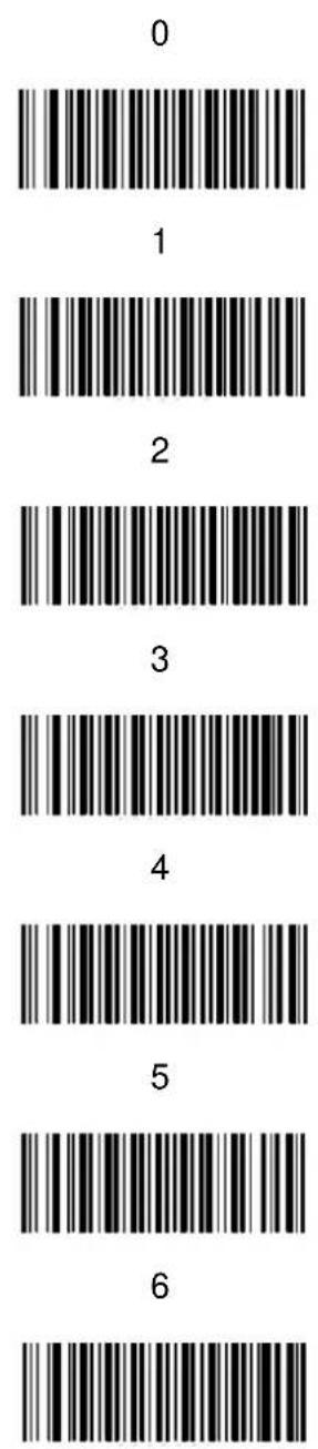
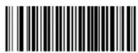
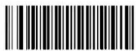
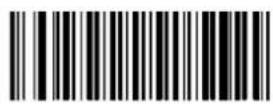
Digit Barcodes
7
8
9
A
B
C
D
E
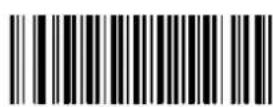
F
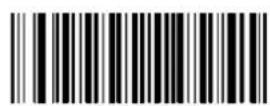
Enter Setup
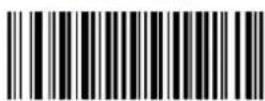
Exit Setup
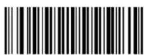
Appendix C - Save/Cancel
Barcodes
After reading numeric barcode(s), you need to scan the Save barcode to save the data. If you scan the wrong digit(s), you can either scan the Cancel barcode and then start the configuration all over again, or scan the Delete the Last Digit barcode and then the correct digit, or scan the Delete All Digits barcode and then the digits you want.
For instance, after reading the Maximum Length barcode and numeric barcodes "1", "2" and "3", you scan:
Delete the Last Digit: The last digit "3" will be removed.
Delete All Digits: All digits "123" will be removed.
Cancel: The maximum length configuration will be cancelled. And the engine is still in the setup mode.
Save
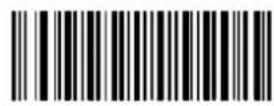
Delete All Digits
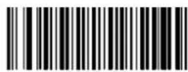
Delete the Last Digit
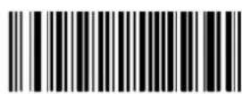
Cancel
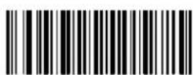
Enter Setup
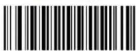
Exit Setup
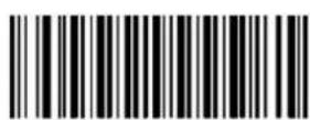
- Wireless 2D Pocket Scanner
- User's Manual
- Preface
- About This Manual
- Regulatory Compliance Statements
- FCC Warning Statement
- FCC Label Statement
- RF Radiation Exposure Statement
- Canadian Compliance Statement
- European Conformity Statement
- CE RF Exposure Compliance
- CE Mark Warning
- CE
- RoHS Statement
- Waste electrical and electronic equipment (WEEE)
- Taiwan NCC Warning Statement
- 低功率電波輻射性電機管理辦法
- LED Information
- Battery Notice
- CAUTION!
- Battery charge notice
- Storage and safety notice
- Product Operation and Storage Notice
- Adapter Notice
- Hearing Damage Warning
- Zx.3 Warning
- Worldwide Support
- Warranty Policy
- Table of Contents
- Preface....i
- Chapter 1 - Overview....1
- Chapter 2 - Installation....20
- Chapter 3 – Symbology ......22
- Chapter 4 – Command Settings....77
- Appendix A – Parameter Programming Examples .....95
- Appendix B - Digit Barcodes....101
- Appendix C - Save/Cancel Barcodes....103
- Chapter 1 - Overview
- Package
- The standard package contents
- Optional accessories
- Scanner Detail
- Micro USB Connector
- Specifications
- Getting Started
- Connect Dongle to Host
- Battery Charging
- LED Indicator / Beeper Sequence
- Display Menu Tree
- Chapter 2 - Installation
- Scanner Type
- NOTE:
- Chapter 3 – Symbology
- All symbologies
- Enable/Disable 1D / 2D Symbologies
- Enable/Disable 1D Symbologies
- Enable/Disable 2D Symbologies
- 1D
- Code 128
- GS1-128 (UCC/EAN-128)
- AIM-128
- EAN-8
- Transmit Check Digit
- Add-On Code
- Disable 2-Digit Add-On Code/ Disable 5-Digit Add-On Code:
- Add-On Code Required
- EAN-8 Extension
- Enable EAN-8 Zero Extend:
- EAN-13
- Transmit Check Digit
- Add-On Code
- Enable 2-Digit Add-On Code/ Enable 5-Digit Add-On Code:
- EAN-13 Beginning with 290 Add-On Code Required
- EAN-13 Beginning with 378/379 Add-On Code
- Required
- EAN-13 Beginning with 414/419 Add-On Code
- EAN-13 Beginning with 434/439 Add-On Code
- EAN-13 Beginning with 977 Add-On Code
- EAN-13 Beginning with 978 Add-On Code
- EAN-13 Beginning with 979 Add-On Code
- ISSN
- Add-On Code
- ISBN
- Set ISBN Format
- Add-On Code
- Transmit System Character "0"
- UPC-E Extension
- UPC-A
- Transmit Check Digit
- Add-On Code
- Transmit Preamble Character
- Interleaved 2 of 5
- Check Digit Verification
- Do Not Transmit Check Digit After Verification:
- Transmit Check Digit After Verification:
- ITF-14
- ITF-6
- Matrix 2 of 5
- Check Digit Verification
- Industrial 2 of 5
- Check Digit Verification
- Standard 2 of 5 (IATA 2 of 5)
- Check Digit Verification
- Code 39
- Check Digit Verification
- Enable/Disable Code 39 Full ASCII
- Code 32
- Code 32 Prefix
- Transmit Code 32 Check Digit
- Transmit Code 32 Start/Stop Character
- Codabar
- Check Digit Verification
- Transmit Start/Stop Character
- Start/Stop Character Format
- Code 93
- Check Digit Verification
- GS1-Databar (RSS)
- Transmit Application Identifier "01"
- Code 11
- Transmit Check Digit
- Check Digit Verification
- Plessey
- Check Digit Verification
- MSI-Plessey
- Transmit Check Digit
- Check Digit Verification
- JAN
- JAN Code for Magazines
- JAN Code for Books
- 2D
- PDF 417
- Character Encoding
- Enable/Disable PDF417 ECI Output
- QR Code
- Micro QR
- Character Encoding
- Enable/Disable QR ECI Output
- Data Matrix
- Rectangular Barcode
- Character Encoding
- Enable/Disable Data Matrix ECI Output
- Chinese Sensible Code
- Enable/Disable Chinese Sensible Code ECI
- Output
- Chapter 4 - Command Settings
- Operation Mode
- Auto
- Batch
- Wedge
- System setting
- Default
- Display FW version / Data Format
- Auto Power Off
- Power Saving
- RF Config.
- Paired device info.
- Remove the pair
- Data & Memory
- Send Batch
- Erase last memory entry
- Erase all data in buffer (Erase Memory)
- Check buffer memory space
- Data Sending Block Delay
- HID Keyboard Character Delay
- HID keyboard Case
- HID keyboard language
- Beep & Vibration & Indicators
- Beep Control
- High volume
- Medium volume \*
- Low volume
- Mute
- Vibration
- Beep & Vibration Setting manually
- Indicators
- Good Read Indicator
- Button Indicator
- System Setting Indicator
- System Warning/Error Indicator
- Power On Indicator
- Power Off Alarm
- Data Terminator
- 1:1 / 1:N Checking Indicators
- 1:1/1:N Checking Pass Indicator
- 1:1/1:N Checking Fail Indicator
- Pause Scan When 1:1/1:N Checking Fail
- 1:1/1:N Checking Screen Indicator
- Appendix A - Parameter
- Programming Examples
- Appendix B -
- Digit Barcodes
- Appendix C - Save/Cancel
- Barcodes
Brand : Unitech
Model : MS926P
Category : Barcode scanners