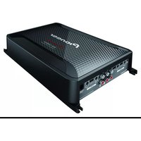
GM-D9604 - Amplifier PIONEER - Free user manual and instructions
Find the device manual for free GM-D9604 PIONEER in PDF.


| Product Type | Bridgeable Four-Channel Power Amplifier |
| Brand | Pioneer |
| Model | GM-D9604 |
| Power Source | 14.4 V DC (10.8 V to 15.1 V allowable) |
| Grounding System | Negative type |
| Current Consumption | 42 A (at continuous power, 4 Ω) |
| Average Current Drawn | 3.3 A (4 Ω for four channels), 5.6 A (4 Ω for two channels, BRIDGE), 5.6 A (2 Ω for four channels) |
| Fuse | 40 A × 2 (internal) |
| Dimensions (W × H × D) | 315 mm × 60 mm × 200 mm |
| Weight | 2.9 kg (leads for wiring not included) |
| Maximum Power Output | 260 W × 4 (4 Ω) / 800 W × 2 (4 Ω) BRIDGE / TOTAL 1600 W (400 W × 4) |
| Continuous Power Output (CEA-2006) | 130 W × 4 (at 14.4 V, 4 Ω, 20 Hz to 20 kHz, ≤ 1% THD) |
| Load Impedance | 4 Ω (1 Ω to 8 Ω allowable) |
| Frequency Response | 10 Hz to 50 kHz (+0 dB, -3 dB) |
| Signal-to-Noise Ratio | 95 dB (IEC-A network) |
| Distortion | 0.05% (10 W, 1 kHz) |
| Low-Pass Filter | Cutoff frequency: 40 Hz to 500 Hz, slope: -12 dB/oct |
| High-Pass Filter | Cutoff frequency: 40 Hz to 500 Hz, slope: -12 dB/oct |
| Bass Boost | Frequency: 50 Hz, Level: 0 dB to 18 dB |
| Gain Control (RCA) | 200 mV to 6.5 V |
| Gain Control (Speaker) | 0.8 V to 16 V |
| Maximum Input Level/Impedance (RCA) | 6.5 V / 25 kΩ |
| Maximum Input Level/Impedance (Speaker) | 16 V / 12 kΩ |
| Protection Function | Thermal, DC offset, short circuit (POWER/PROTECT indicator turns red) |
| Recommended Speaker Impedance | 2 Ω to 8 Ω (4 Ω to 8 Ω for bridge connections) |
Frequently Asked Questions - GM-D9604 PIONEER
User questions about GM-D9604 PIONEER
0 question about this device. Answer the ones you know or ask your own.
Ask a new question about this device
Download the instructions for your Amplifier in PDF format for free! Find your manual GM-D9604 - PIONEER and take your electronic device back in hand. On this page are published all the documents necessary for the use of your device. GM-D9604 by PIONEER.
USER MANUAL GM-D9604 PIONEER
BRIDGEABLE FOUR-CHANNEL POWER AMPLIFIER
ThankyouforpurchasingthisPIONEER product
Toensureproperuse, pleasereadthrough this manualbeforeusingthisproduct.Itisesespeciallyimportantthatyoureadandobserve
WARNINGSandCAUTIONsinthismanual.
Please keep the manual in as safe and accessible place for future reference.

Visitourwebsite
Visitusatthefollowingsite:
http://pioneer.jp/group/index-e.html
Weofferthelatestinformationabout
PIONEERCORPORATION Nonour website.

Ifyouexperienceproblems
Should this product fail to operate properly, please contact your dealer or nearest authorized Pioneer Service Station.
Beforeconnecting/ installingtheamplifier

WARNING
- Thisunitisforvehicleswitha12Vbatteryandnegativegrounding.Beforeinstallinginrecreationalvehicles,trucksorbuses,checkthe batteryvoltage.
- Wheninstallingthisunit,makesuretoconnectthegroundwirefirst.Ensurethatthe groundwireisproperlyconnectedtometal partsofthecar'sbody.Thegroundwireofthe oneofthisunitmustbeconnectedtothecar separatelywithdifferentscrews.Ifthescrew forthegroundwireloosensorfallsout,it couldresultinfire;generationofsmokeor malfunction.
- Besuretoinstallthefusetothebatterywire.
• Alwaysuseafuseoftheratingprescribed. Theuseofanimproperfusecouldresultin overheatingandsmoke,damagetotheproductandinjury,includingburns.
- Checktheconnectionsofthepowersupply andspeakersifthefuseoftheseparatelysold batterywireortheamplifierfuseblows.Determineandresolvethecause,thenreplacethe fusewithandidenticalequivalent.
- Alwaysinstalltheamplifieronaflatsurface. Donotinstalltheamplifieronasurfacethat isnotflatoronasurfacewithaprotrusion. Doingsocouldresultinmalfunction.
- Wheninstallingtheamplifier,donotallow partssuchasextrascrewstogetcaughtbetweentheamplifierandtheautomobile.Doingsocouldcausemalfunction.
- Donotallowthisunittocomeintocontact with liquids. Electricalshockcouldresult. Also, damagetothisunit, smoke, and over-heating could result from contact with liquids. Thesurfaces of the amplifier and any attached speakers may also heatup and cause minor burns.
- Intheeventofanyabnormality, thepower supplytotheamplifieriscutofftoprevent equipmentmalfunction. If this occurs, switch thesystempoweroffandcheckthepower supplyandspeakerconnections. If you are unable to determine the cause, please contact your dealer.
- Always disconnect then negative terminal of the battery before hand to avoid the risk of electric shockor short circuit during installation.
- Donotattempttodisassembleormodifythis unit.Doingsomayresultinfire,electric shockorothermalfunction.

CAUTION
• Always keep the volumelowen ought to hear outsidesounds.
- Extended use of the car stereowhile the engine is at restoridling may exhaust the battery.
Beforeyoustart
About the protection function
Thisproducthasprotectionfunction. Whenthis productdetectssomethingabnormal, the following functions will operate to protect the product and speaker output.
- The POWER/PROTECT indicator will turn red and the amplifier will shutdown in the situations outlined below.
—If the temperature inside the amplifier gets too high.
—IfaDCvoltageisappliedtothespeaker outputterminal. - The POWER/PROTECT indicator will turn red and the output will be muted in the situations outlined below.
—If the speaker output terminal and speaker wire a short-circuited.
What'swhat
Frontside

Rearside

Toadjusttheswitch, useaflatheadscrewdriverifneeded.
①POWER/PROTECTindicator
The power indicator lights up to indicate power ON.
- If something is not normal, the indicator turns red.
②FREQ(cutofffrequency)control
Cutofffrequencyselectablefrom40Hzto 500HziftheLPF/HPFselectswitchissetto LPForHPF.
③GAIN(gain)control
AdjustinggaincontrolsCHANNELA(channelA)andCHANNELB(channelB)helps alignthecarstereooutputtothePioneer amplifier.DefaultsettingistheNORMAL position.
Ifoutputremainslow,evenwhenthecar stereovolumeisturnedup,turncontrolsto lowerlevel.Ifdistortionoccurswhenthecar stereovolumeisturnedup,turnthesecontrolstohigherlevel.
- Ifusingonlyoneinputplug, setthegain controlsforspeakeroutputsAandBto thesameposition.
- ForusewithanRCAequippedcarstereo (standardoutputof500mV),settothe NORMALposition.ForusewithanRCA
equippedPioneercarstereo,withmaxi- mumoutputof4Vormore,adjustlevel tomatchthatofthecarstereooutput.
- ForusewithanRCAequippedcarstereo withoutputof4V,settotheHposition.
④LPF(low-passfilter)/HPF(high-passfilter)selectswitch
Switchthesettingsbasedontheconnected speaker.
- WhentheSubwooferisconnected: SelectLPF. This eliminates high range frequency and outputs low range frequency.
- Whenthefullrangespeakerisconnected: Select HPF or OFF. HPF eliminates low rangefrequencyandoutputhighrange frequency.OFFoutputstheentirefrequencyrange.
⑤INPUTSELECT(inputselect)switch
Select2CHfortwo-channelinputand4CH forfour-channelinput.
⑥BASSBOOSTREMOTE(bassboostlevel remotecontrol)jack
ByconnectingtheBassboostlevelremote controltothejackonthemainunit,youwill beabletoselectabassboostlevelfrom 0dBto18dB.
- Bassboostlevelsettingappliesonlyto CHANNELB(channelB)output.
- Forinstructionofconnectingthebass boostremotecontroltotheamplifier,see theConnectiondiagramonpage6.
Settinggainproperly
- Protectivefunctionincludedtoprevent malfunctionoftheunitand/orspeakers duetoexcessiveoutput,improperuseor improperconnection.
Settingtheunit
- When outputting high volumesoundetc., this function cut soffthe output for a few seconds as anormal function, but output is restored when the volume of the head unit is turned down.
- Acutinsoundoutputmayindicateimpropersettingofthegaincontrol.Toensure continuoussoundoutputwiththehead unitatahighvolume,setamplifiergain controltoalevelappropriateforthepreout maximumoutputleveloftheheadunit,so thatvolumecanremainunchangedandto controlexcessoutput.
- Despitecorrectvolumeandgainsettings, theunitsoundstillcutsoutperiodically.In suchcases,pleasecontactthenearest authorizedPioneerServiceStation.
Gaincontrolofthisunit
Preoutlevel:2V(Standard:500mV)
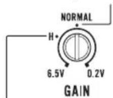
Preoutlevel:4V
AboveillustrationshowsNORMALgainsetting.
Relationshipbetweenamplifiergain andheadunitoutputpower

Ifamplifiergainisraisedimproperly, this will simply increased distortion, with little increase in power.
Signalwaveformwhenoutputtingat highvolumeusingamplifiergain control

Signalwaveformdistortedwithhighoutput,if youraisethegainoftheamplifierthepower changesonlyslightly.
Connectiondiagram
![graph TD A["1"] --> B["2"] B --> C["3"] C --> D["4"] D --> E["5"] E --> F["6"] F --> G["7"] G --> H["8"] H --> I["9"] I --> J["10"] J --> K["11"] K --> L["12"] L --> M["13"] M --> N["14"] N --> O["15"] O --> P["16"] P --> Q["17"] Q --> R["18"] R --> S["19"] S --> T["20"] T --> U["21"]](/content/2026/05/950690/images/5217faae8ebd8758b432a21ce727169684b9a61b4cca6cb5449a34ab247a2b78.jpg)
①Batterywire(soldseparately)
- Themaximumlengthofthewirebetweenthefuseandthepositive⊕terminalofthebatteryis30cm.
- Forthewiresize,refertoConnectingthe powerterminalonpage10.Thebattery wire,thegroundwireandtheoptional directgroundwiremustbesamesize. Aftermakingallotherconnectionsat theamplifier,connectthebatterywire terminaloftheamplifiertothepositive ⊕terminalofthebattery.
②Fuse(100A)(soldseparately)
Eachamplifiermustbeseparatelyfusedat 100A.
③Positive(⊕)terminal
④Negative(⊖)terminal
⑤Battery(soldseparately)
⑥Groundwire, Terminal(soldseparately) Thegroundwiresmustbesamesizeasthe batterywire.
Connecttometalbodyorchassis.
⑦CarstereowithRCAoutputjacks(soldseparately)
⑧Externaloutput Ifonlyoneinputplugisused,donotconnect anythingtoRCAinputjackB.
⑨ConnectingwirewithRCApinplugs(soldseparately)
⑩RCAinputjackA
⑪RCAinputjackB
⑫AmplifierwithRCAinputjacks(soldseparately)
⑬RCAoutputjack OutputsthesignalinputtoCHA.
⑭Speakeroutputterminals Pleaseseethefollowingsectionforspeaker connectioninstructions.RefertoConnections whenusingthespeakerinputwireonpage9.
⑮Systemremotecontrolwire(soldseparately) Connectmaleterminalofthiswiretothesystemremotecontrolterminalofthecarstereo. Thefemaleteminalcanbeconnectedtothe auto-antennarelaycontrolterminal.Ifthecar stereolacksasystemremotecontrolterminal, connectthemaleteminaltothepowerterminalviatheignitionswitch.
⑯Fuse(40A)×2
⑰Frontside
⑱Rearside
⑲Bassboostlevelremotecontrolwire(5m)
⑳Bassboostlevelremotecontrol
Note
INPUTSELECT(inputselect)switchmustbeset.
Fordetails,seeSettingtheunitonpage4.

Beforeconnectingthe amplifier

WARNING
- Securethewiringwithcableclampsoradhesivetape.Toprotectthewiring,wrapsections incontactwithmetalpartsinadhesivetape.
Connectingtheunits
- Nevercuttheinsulationofthepowersupply tofeedpowertootherequipment.Currentcapacityofthewireislimited.

CAUTION
- Nevershortenanywires, the protection circuit may malfunction.
- Neverwirethespeakernegativecabledirectlytoground.
- Neverbandtogethermultiplespeaker'snegativecables.
- If the system remote control wire of the amplifier is connected to the power terminal via the ignition switch (12VDC), the amplifier will remain on with the ignition whether the car stereoisonoroff, which may exhaust battery if the engine is at restoridling.
• Installandroutetheseparatelysoldbattery wireasfaraspossiblefromthespeakerwires.Installandroutetheseparatelysoldbattery wire,groundwire,speakerwiresandtheamplifierasfarawayaspossiblefromtheantenna,antennacableandtuner.
Aboutbridgedmode
Diagram A - Proper

2 Ω Bridged Mode
Diagram B - Improper

1 Ω Bridged Mode
- Donotinstallorusethisamplifierbywiring speakersratedat2Ω(orlower)inparallelto achievea1Ω(orlower)bridgedmode(DiagramB).
Amplifierdamage,smoke,andoverheating couldresultfromimproperbridging.Theamplifiersurfacecouldalsobecomehottothe touchandminorburnscouldresult.
Toproperlyinstalloruseabridgedmode and achievea2Ωload, wiretwo4Ωspeakersin parallelwithLeft⊕andRight⊖(DiagramA) oruseasingle2Ωspeaker. Inaddition, refertothespeakerinstruction manualforinformationonthecorrectconnectionprocedure.
- Foranyfurtherenquiries,contactyourlocal authorizedPioneerdealerorcustomer service.
Aboutsuitable specificationofspeaker
Ensurespeakersconformtothefollowing standards, otherwisethereisariskoffire, smokeordamage. Speakerimpedance is 2Ω to 8 Ω, or 4 Ω to 8 Ω for two-channel and other bridgeconnections.
Subwoofer
| SpeakerchannelPower | ||
| Four-channeloutput | Nominalinput: Min.130W | |
| Two-channeloutput | Nominalinput: Min.400W | |
| Three-channel output | Speakeroutput A | Nominalinput: Min.130W |
| Speakeroutput B | Nominalinput: Min.400W | |
Otherthansubwoofer
| SpeakerchannelPower | ||
| Four-channeloutput | Max.input:Min.260W | |
| Two-channeloutput | Max.input:Min.800W | |
| Three-channel output | SpeakeroutputA | Max.input:Min.260W |
| SpeakeroutputB | Max.input:Min.800W | |

Connectingthespeakers
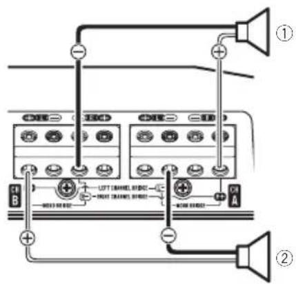
Thespeakeroutputmodecanbefour-channel, three-channel(stereoandmono)ortwo-channel(stereoormono).Connectthespeaker leadsbasedonthemodeandthefigures shownbelow.
Four-channeloutput
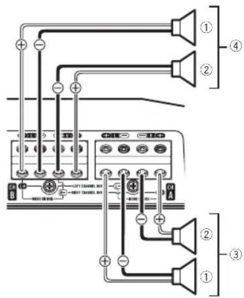
①Left
②Right
③SpeakeroutputA
④SpeakeroutputB
Two-channeloutput(Stereo)
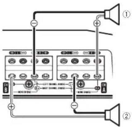
①Speakeroutput(Right)
②Speakeroutput(Left)
Two-channeloutput(Mono)

①Speakeroutput(Mono)
Three-channeloutput
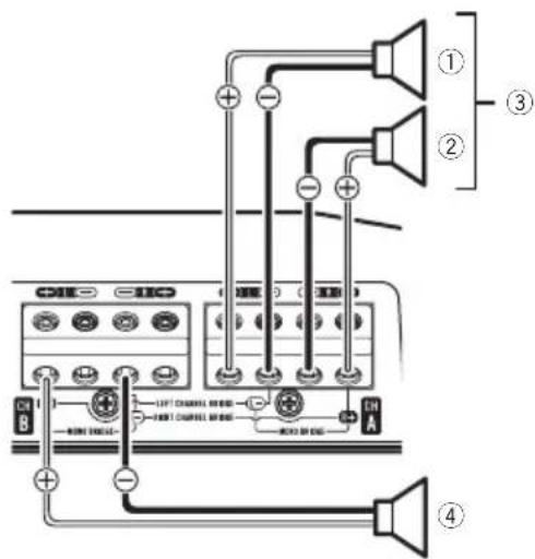
①Left
②Right
③SpeakeroutputA
④SpeakeroutputB(Mono)

Connectionswhenusing theRCAinputjack
ConnectthecarstereoRCAoutputjackand theRCAinputjackoftheamplifier.
•TheRCAoutputjackofthisunitoutputs thesignalthatcomesfromTheRCAinput jackA.
Connectingtheunits
Four-channel/Three-channeloutput
- SlideINPUTSELECT(inputselect)switch to4CHposition.

①RCAinputjackA
②RCAinputjackB
③ConnectingwireswithRCAplugs(soldseparately)
④Fromcarstereo(RCAoutput)
Ifonlyoneinputplugisused, e.g. when the carstereohasonlyoneoutput(RCAoutput), connecttheplugtoRCAinputjackArather than B.
⑤INPUTSELECT(inputselect)switch(4CHposition)
Two-channeloutput(Stereo)/(Mono)
- SlideINPUTSELECT(inputselect)switch to2CHposition.

①RCAinputjackA
Fortwo-channeloutput,connecttheRCA plugstotheRCAinputjackA.
②ConnectingwirewithRCApinplugs(soldseparately)
③Fromcarstereo(RCAoutput)
④INPUTSELECT(inputselect)switch(2CH position)
Connectionswhenusing thespeakerinputwire
Connectthecarstereospeakeroutputwires totheamplifierusingthesuppliedspeaker inputwirewithRCApincord.
![graph LR A["①"] --> B["②"] B --> C["③"] C --> D["④"] D --> E["⑤"] E --> F["⑥"] F --> G["⑦"] G --> H["Output Terminal"] style A fill:#f9f,stroke:#333 style G fill:#bbf,stroke:#333](/content/2026/05/950690/images/c9626a83eacd668994f56f10f6aee7beeb9b3b42b3adb3da83e222b8e4109a78.jpg)
①CarStereo
②Speakeroutput
③Red:Right⊕
④Black:Right
⑤Black:Left
⑥White:Left⊕
⑦SpeakerinputwirewithRCApincord
TotheRCAinputjackofthisunit
Notes
- If speaker wires with an RCA pincord from a head unit are connected to this amplifier, the amplifier will automatically turn on when the head unit is turned off. When the head unit is turned off, the amplifier turns off automatically. This function may not work with some head units. In such cases, please use as system remote control wire (sold separately). If multiple amplifiers are to be connected together synchronously, connect the head unit and all amplifiers via the system remote control wire.
- Connectthesystemremotecontrolwirewhen youwishtonlyturnonthecarstereo,notthe amplifier.
Connectingtheunits
- This amplifier automatically selects an input signal mode between the RCA level and the speaker level by detecting an input signal.

Solderlessterminal connections
- Sincethewirewillbecomelooseovertime, itmustbeperiodicallyinspectedandtightenedasnecessary.
- Donotsolderorbindtheendsofthe twistedwires.
- Fastenwhilemakingsuretonottoclamp theinsulatingsheathofthewire.
- Usethesuppliedhexagonalwrenchto tightenandloosentheterminalscrewof theamplifieranduseittosecurelyfasten thewire.Becarefultoavoidexcessivetighteningofthisscrew,whichmaydamage thewire.
Connectingthepowerterminal

WARNING
If the battery wire is not securely fixed to the terminal using the terminals, there is a risk of overheating, malfunction and injury, including minor burns.
- Alwaysusetherecommendedbatteryand groundwire,whichissoldseparately.Connectthebatterywiredirectlytothecarbaterypositive(⊕)terminalandtheground wiretothecarbody.
- Recommendedwiressize(AWG:American WireGauge)isasfollows.Thebatterywire, thegroundwireandtheoptionaldirect groundwiremustbesamesize.
- Useawireof8AWGto16AWGwireforthe speakerwire.
Batterywireandgroundwiresize
WirelengthWiresize
lessthan2.2m8AWG
lessthan3.6m6AWG
lessthan6.4m4AWG
1Routebatterywirefromenginecompartmenttothevehicleinterior.
- Whendrillingacablepass-holeintothevehiclebodyandroutingabatterywirethoroughit,takecarenottoshort-circuitthe wiredamagingitbythecutedgesorburrs ofthehole.
Aftercompletingallotheramplifierconnections, finallyconnectthebatterywireterminal oftheamplifiertothepositive(⊕)battery terminal.
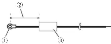
①Positive(⊕)terminal
②Batterywire(soldseparately)
Themaximumlengthofthewirebetween thefuseandthepositive⊕terminalofthe batteryis30cm.
③Fuse(100A)(soldseparately)
Eachamplifiermustbeseparatelyfusedat 100A.
Connectingtheunits
2Usewirecuttersorautilityknifeto striptheendofthebatterywire,ground wireandsystemremotecontrolwiretoexposeabout10mmoftheendofeachof thewires,andthentwisttheexposedends ofthewires.

3Connectthewirestotheterminal.
Fixthewiressecurelywiththeterminal screws.
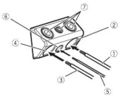
①Batterywire
②Powerterminal
③Groundwire
④GNDterminal
⑤Systemremotecontrolwire
⑥Systemremotecontrolterminal
⑦Terminalscrews
Connectingthespeakeroutput terminals
1Usewirecuttersorautilityknifeto striptheendofthespeakerwirestoexposeabout10mmofwireandthentwist thewire.

2Connectthespeakerwirestothe speakeroutputterminals.
Fixthewiressecurelywiththeterminal screws.
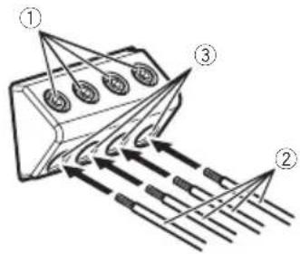
①Terminalscrews
②Speakerwires
③Speakeroutputterminals

Beforeinstallingtheamplifier

WARNING
- Toensureproperinstallation, usethesupplied partsinthemannerspecified. Ifanyparts otherthanthosesuppliedareused, they may damage internal part of the amplifier, or be-come loose causing the amplifiertoshut down.
- Donotinstallin: —Placeswhereitcouldinjurethedriveror passengersifthevehiclestopssuddenly. —Placeswhereitmayinterferewiththedriver,suchasonthefloorinfrontofthedriver'sseat.
- Installtappingscrewsinsuchawaythatthe screwtipdoesnottouchanywire.Thisisimportanttopreventwiresfrombeingcutbyvibrationofthecar,whichcanresultinfire.
- Makesurethatwiresdonotgetcaughtinthe slidingmechanismoftheseatsortouchthe legsofapersoninthevehicleasshort-circuit mayresult.
- Whendrillingtoinstalltheamplifier,always confirmnopartsarebehindthepaneland protectallcablesandimportantequipment (e.g.fuel/brakelines,wiring)fromdamage.

CAUTION
- Toensureproperheatdissipationoftheamplifier,ensurethefollowingduringinstallation: —Allowadequatespaceabovetheamplifier forproperventilation. —Donotcovertheamplifierwithafloormat orcarpet.
- Placeallcablesawayfromhotplaces,such asneartheheateroutlet.
- Theoptimal installation location differs depending on the car model. Secure the amplifier at sufficiently rigid location.
- Checkallconnectionsandsystemsbefore finalinstallation.
- Afterinstallingtheamplifier,confirmthatthe sparetire,jackandtoolscanbeeasilyremoved.
AttachingtheBassboost remotecontrol
Attachwithtappingscrews(3mm×10mm) ataneasilyaccessiblelocationsuchasunder thedashboard.
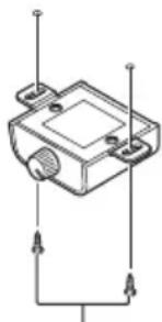
Tappingscrews(3mm×10mm)

Exampleofinstallationon thefloormatorchassis
1Placetheamplifierinthedesiredinstallationlocation.
Insert the supplied tappings screws (4mm × 18mm) into the screw wholes and push on the screw with a crew driver so they make an imprint where the installation holes are to be located.
2Drill2.5mmdiameterholesattheimprintseitheronthecarpetordirectlyon thechassis.
Installation
3Installtheamplifierwiththeuseof suppliedtappingscrews(4mm×18mm).

①Tapping-screws(4mm×18mm)
②Drilla2.5mmdiameterhole
③Floormatorchassis
④Hole-to-holedistance:307mm
⑤Hole-to-holedistance:181mm

Additionalinformation
Specifications
Powersource....14.4VDC(10.8Vto15.1V allowable)
Groundingsystem......Negativetype
Currentconsumption......42A(atcontinuouspower, 4Ω)
Averagecurrentdrawn......3.3A(4Ωforfourchannels) 5.6A(4Ωfortwochannels, BRIDGE) 5.6A(2Ωforfourchannels)
Fuse....40A×2
Dimensions(W×H×D)...315mm×60mm×200mm
Weight....2.9kg(Leadsforwiringnot included)
Maximumpoweroutput.....260W×4(4Ω)/800W×2 (4Ω)BRIDGE/TOTAL 1600W(400W×4)
Continuous power output ... 130 W × 4 (at 14.4 V, 4 Ω, 20 Hz to 20 kHz, ≤ 1% THD)
200W×4(at14.4V,2Ω, 1kHz,≤1%THD)
130W×4(at14.4V,1Ω, 1kHz,≤1%THD)
400W×2(at14.4V,4Ω
BRIDGE,1kHz,≤1%THD)
260W×2(at14.4V,2Ω
BRIDGE,1kHz,≤1%THD)
Load impedance ....4Ω (1Ω to 8Ω allowable)
Frequencyresponse.....10Hzto50kHz(+0dB, -3dB)
Signal-to-noiseratio....95dB(IEC-Anetwork)
Distortion....0.05%(10W,1kHz)
Lowpassfilter: Cutofffrequency.....40Hz to 500Hz Cutoffslope.....-12dB/oct
Highpassfilter: Cutofffrequency.....40Hz to 500Hz Cutoffslope.....-12dB/oct
Bassboost: Frequency.....50Hz Level.....0dBto18dB
Gaincontrol: RCA....200mVto6.5V Speaker....0.8Vto16V
Maximum input level/impedance: RCA....6.5V/25kΩ Speaker....16V/12kΩ
Notes
- Specificationsandthedesignaresubjecttomodificationswithoutnotice.
- Theaveragecurrentdrawnisnearlythemaxi-mumcurrentdrawnbythisunitwhenan audiosignalisinput. Use this value when working out total current drawn by multiple power amplifiers.
Partetrasera

Paraajustarelinterruptor, siesprecisoutilice undestornilladordecabezaplana.
①IndicadorPOWER/PROTECT
①Izquierda
②Derecha
③SalidadealtavozA
④SalidadealtavozB
Salidadedoscanales(estéreo)
①Izquierda
②Derecha
③SalidadealtavozA
① Cabledebatería
② Terminaldepotencia
③ Cabledepuestaatierra
④ Terminaldepuestaatierra
Tornillosderoscacortante(3mm×10mm)

PIONEERCORPORATION Nemnossosite.

Sehouverproblemas
Partetraseira

①Daesquerda
②Dadireita
①Terminalpositivo(⊕)
②Fiodabateria(vendidoseparadamente) Ocomprimentomáximodofioentreofusí-veleoterminalpositivo⊕dabateriaéde 30cm.
③Fusível(100A)(vendidoseparadamente) Cadaamplificadordeveserligadoseparadamenteporfusíveisde100A.
2Usecortadoresdefioouumafacapara desencaparapontadofiodabateria,do fio-terraedofiodocontroleremotodosistemaexporcercade10mmdaextremidadedecadafio.Emseguida,gireas extremidadesexpostasdosfios.
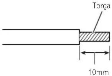
3Conecteosfiosaoterminal.
Prendaosfioscomfirmezautilizandoospara-fusosdoterminal.
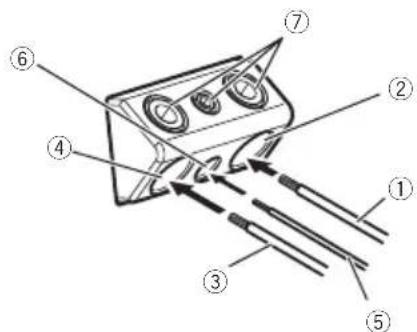
①Fiodabateria
②Terminaldepotência
③Fioterra
④TerminalGND
⑤Fiodocontroleremotodosistema
⑥Terminaldocontroleremotodosistema
⑦Parafusosdoterminal
Conexãodasunidades
①Parafusosdoterminal
②Fiosdoalto-falante
Parafusosatarrachantes(3mm×10mm)

(1 8 × 1 8 ملم ) ①
کرتلبق

① الطرف الموجب (⊕)
Visit us on the World Wide Web at
http://pioneer.jp/group/index-e.html
Pioneer Gulf.FZE
http://www.pioneer-uae.com
Pioneer Electronics Australia. Pty.Ltd
http://www.pioneer.com.au/
Pioneer Electronics Asiacentre.Pte
http://www.pioneer.com.sg
Pioneer (HK) Ltd.
http://www.pioneerhongkong.com.hk
Pioneer High Fidelity Taiwan Co., Ltd.
http://www.pioneer-twn.com.tw
Pioneer International Latin America S.A.
http://www.pioneer-latin.com
PIONEERCORPORATION
1-1, Shin-ogura, Saiwai-ku, Kawasaki-shi,
Kanagawa212-0031, JAPAN
PIONEERELECTRONICS(USA)INC.
P.O.Box1540,LongBeach,California90801-1540,U.S.A.
TEL:(800)421-1404
PIONEEREUROPENV
Haven1087, Keetberglaan1, B-9120Melsele, Belgium/Belgique
TEL:(0)3/570.05.11
PIONEERELECTRONICSASIACENTREPTE.LTD.
253AlexandraRoad,#04-01,Singapore159936
TEL:65-6472-7555
PIONEERELECTRONICSAUSTRALIAPTY.LTD.
5ArcoLane,Heatherton,Victoria,3202Australia
TEL:(03)9586-6300
PIONEERELECTRONICSOFCANADA, INC.
340FerrierStreet, Unit2, Markham, OntarioL3R2Z5, Canada
TEL:1-877-283-5901
TEL:905-479-4411
PIONEERELECTRONICSDEMEXICO,S.A.deC.V.
Blvd.ManuelAvilaCamacho13810piso
Col.LomasdeChapultepec,Mexico,D.F.11000
TEL:55-9178-4270
先鋒股份有限公司
台北市內湖區瑞光路407號8樓
電話:886-(0)2-2657-3588
先鋒電子(香港)有限公司
香港九龍長沙灣道909號5樓
電話:852-2848-6488
©2012PIONEERCORPORATION.
Allrightsreserved.


- THANKYOUFORPURCHASINGTHISPIONEER PRODUCT
- VISITOURWEBSITE
- IFYOUEXPERIENCEPROBLEMS
- BEFORECONNECTING/ INSTALLINGTHEAMPLIFIER
- WARNING
- CAUTION
- BEFOREYOUSTART
- ABOUT THE PROTECTION FUNCTION
- WHAT'SWHAT
- ①POWER/PROTECTINDICATOR
- ②FREQ(CUTOFFFREQUENCY)CONTROL
- ③GAIN(GAIN)CONTROL
- ④LPF(LOW-PASSFILTER)/HPF(HIGH-PASSFILTER)SELECTSWITCH
- ⑤INPUTSELECT(INPUTSELECT)SWITCH
- ⑥BASSBOOSTREMOTE(BASSBOOSTLEVEL REMOTECONTROL)JACK
- SETTINGGAINPROPERLY
- SETTINGTHEUNIT
- NOTE
- BEFORECONNECTINGTHE AMPLIFIER
- CONNECTINGTHEUNITS
- ABOUTBRIDGEDMODE
- ABOUTSUITABLE SPECIFICATIONOFSPEAKER
- CONNECTINGTHESPEAKERS
- CONNECTIONSWHENUSING THERCAINPUTJACK
- FOUR-CHANNEL/THREE-CHANNELOUTPUT
- TWO-CHANNELOUTPUT(STEREO)/(MONO)
- CONNECTIONSWHENUSING THESPEAKERINPUTWIRE
- NOTES
- SOLDERLESSTERMINAL CONNECTIONS
- CONNECTINGTHEPOWERTERMINAL
- BATTERYWIREANDGROUNDWIRESIZE
- WIRELENGTHWIRESIZE
- 1ROUTEBATTERYWIREFROMENGINECOMPARTMENTTOTHEVEHICLEINTERIOR
- 3CONNECTTHEWIRESTOTHETERMINAL
- CONNECTINGTHESPEAKEROUTPUT TERMINALS
- 2CONNECTTHESPEAKERWIRESTOTHE SPEAKEROUTPUTTERMINALS
- BEFOREINSTALLINGTHEAMPLIFIER
- ATTACHINGTHEBASSBOOST REMOTECONTROL
- EXAMPLEOFINSTALLATIONON THEFLOORMATORCHASSIS
- 1PLACETHEAMPLIFIERINTHEDESIREDINSTALLATIONLOCATION
- INSTALLATION
- ADDITIONALINFORMATION
- SPECIFICATIONS
- ①INDICADORPOWER/PROTECT
- SEHOUVERPROBLEMAS
- 2USECORTADORESDEFIOOUUMAFACAPARA DESENCAPARAPONTADOFIODABATERIA,DO FIO-TERRAEDOFIODOCONTROLEREMOTODOSISTEMAEXPORCERCADE10MMDAEXTREMIDADEDECADAFIO.EMSEGUIDA,GIREAS EXTREMIDADESEXPOSTASDOSFIOS
- 3CONECTEOSFIOSAOTERMINAL
- CONEXÃODASUNIDADES
- کرتلبق
- PIONEERCORPORATION
Brand : PIONEER
Model : GM-D9604
Category : Amplifier