
M2-750X5 - Receiver Rockford Fosgate - Free user manual and instructions
Find the device manual for free M2-750X5 Rockford Fosgate in PDF.


| Product Type | 5-Channel Audio Amplifier |
| Brand | Rockford Fosgate |
| Model | M2-750X5 |
| Integrated Technology | C.L.E.A.N. (Calibrated Level Eliminated Audible Noise) with input and output indicators, Punch EQ |
| Power Supply | 9-14.4 V DC |
| Rated Power | 750 W RMS total (estimated) |
| Recommended Impedance | Front/Rear channels: 2 Ω min stereo, 4 Ω min bridged; Sub channel: 2 Ω min |
| Input Types | RCA (low level) and high level with auto-detection |
| Filters | High-pass, low-pass, subsonic (adjustable) |
| Remote Control | RLC (remote level control) included (mono channels) |
| Auto Turn-On | Yes, via DC offset from left front speakers |
| Protection | Protection indicator for short circuit or too low impedance |
| Thermal Dissipation | Aluminum heatsink, minimum 25.4 mm air space required |
| Installation Location | Vehicle interior only (not in engine compartment) |
| Required Wiring | Red power wire (with fuse within 45 cm of battery), black ground wire (< 30 in), remote wire (or auto turn-on) |
| Hearing Safety | Prolonged exposure > 100 dB may cause permanent hearing loss |
| Package Contents | Amplifier, mounting hardware, Allen wrench, RLC, wire terminals, Molex connectors, downloadable test tones |
| Care | Clean with a soft, dry cloth. Do not use chemicals. |
| Serviceability | Built-in diagnostic lights. In case of failure, contact a qualified technician. |
Frequently Asked Questions - M2-750X5 Rockford Fosgate
User questions about M2-750X5 Rockford Fosgate
0 question about this device. Answer the ones you know or ask your own.
Ask a new question about this device
Download the instructions for your Receiver in PDF format for free! Find your manual M2-750X5 - Rockford Fosgate and take your electronic device back in hand. On this page are published all the documents necessary for the use of your device. M2-750X5 by Rockford Fosgate.
USER MANUAL M2-750X5 Rockford Fosgate
Installation assistance available at: — RFTECH www.rockfordfosgate.com/rftech

600 South Rockford Drive • Tempe, Arizona 85281 United States Direct: (480) 967-3565 • Toll Free: (800) 669-9899
rockfordfosgate.com
Dear Customer,
Congratulations on your purchase of the world's finest brand of audio products. At Rockford Fosgate we are fanatics about musical reproduction at its best, and we are pleased you chose our product. Through years of engineering expertise, hand craftsmanship and critical testing procedures, we have created a wide range of products that reproduce music with all the clarity and richness you deserve.
For maximum performance we recommend you have your new Rockford Fosgate product installed by an Authorized Rockford Fosgate Dealer. Please read your warranty and retain your receipt and original carton for possible future use.
Great product and competent installations are only a piece of the puzzle when it comes to your system. Make sure that your installer is using 100% authentic installation accessories from Rockford Fosgate in your installation. Rockford Fosgate has everything from RCA cables and speaker wire to power wire and battery connectors. Insist on it! After all, your new system deserves nothing but the best.
To add the finishing touch to your new Rockford Fosgate image order your Rockford accessories, which include everything from T-shirts to hats.
Visit our web site for the latest information on all Rockford products; www.rockfordfosgate.com or, in the U.S. call 1-800-669-9899 or FAX 1-800-398-3985. For all other countries, call +001-480-967-3565 or FAX +001-480-966-3983.
2 Introduction
3-4 Specifications
5-7 Design Features
8-10 Installation
Installation Considerations
Mounting Locations
Battery and Charging
Wiring the System
11 Operation
Adjusting Crossover Frequency
Input Switch
C.L.E.A.N.
Punch EQ
Remote Punch Level Control
12 Troubleshooting
13-44 Additional Languages
French
Spanish
German
Italian
48 Limited Warranty Information
Table of Contents
If, after reading your manual, you still have questions regarding this product, we recommend that you see your Rockford Fosgate dealer. If you need further assistance, you can call us direct at 1-800-669-9899. Be sure to have your serial number, model number and date of purchase available when you call.
PRACTICE SAFE SOUND
Continuous exposure to sound pressure levels over 100dB may cause permanent hearing loss. High powered auto sound systems may produce sound pressure levels well over 130dB. Use common sense and practice safe sound.
PRATIQUEZ UNE ÉCOUTE SANS RISQUES
This symbol with “WARNING” is intended to alert the user to the presence of important instructions. Failure to heed the instructions could result in severe injury or death.
This symbol with “CAUTION” is intended to alert the user to the presence of important instructions. Failure to heed the instructions could result in injury or unit damage.

WARNING

CAUTION
To prevent injury and damage to the unit, please read and follow the instructions in this manual.
If you feel unsure about installing this system yourself, have it installed by a qualified Rockford Fosgate technician.
Before installation, disconnect the battery negative (-) terminal to prevent damage to the unit, fire and/or possible injury.
| Mode M2-200X2 M2-300X4 M2-750X5 M2-500X1 | ||||
| Rated Power - Continuous Power Rating (RMS) Measured @ 14.4V | 50x2 @ 4 ohms100x2 @ 2 ohms200x1 @ 4 ohms* | 50x4 @ 4 ohms75x4 @ 2 ohms150x2 @ 4 ohms* | 50x4 @ 4 ohms100x4 @ 2 ohms200x2 @ 4 ohms*Sub: 200x1 @ 4 ohmsSub: 350x1 @ 2 ohms | 300x1 @ 4 ohms500x1 @ 2 ohms |
| Crossover Slope | 12 dB/Oct 12 dB/Oct 12 | dB/Oct 12 dB/Oct | ||
| Crossover Frequency | Variable 50Hz-250HzLP/AP/HP | Variable 50Hz-250HzLP/AP/HP | Variable 50Hz-250HzLP/AP/HPIF: 15Hz-40Hz | Variable LP 50Hz-250HzIF: 15Hz-40Hz |
| Punch EQ | N/A N/A Mono Channel | Only | Variable 0 *18dB@ 45Hz | Variable 0 *18dB@ 45Hz |
| Operating Voltage | 9-16VDC 9-16VDC 9-16VDC 9-16VDC | |||
| Frequency Response | 20Hz-20kHz 20Hz-20kHz F/R: 20Hz-20kHz | Sub: 20Hz-250Hz | 20Hz-250Hz | |
| Battery Fuse Rating (not supplied) | 30A 60A 120A 80A | |||
| Input Sensitivity | 150mV-4V Low Level450mV-12V HighLevel | 150mV-4V Low Level450mV-12V HighLevel | 150mV-4V Low Level450mV-12V HighLevel | 150mV-4V LowLevel450mV-12V HighLevel |
| S/N Ratio CTA 2006 | >80dB >70dB F/R: >80dB | Sub: >75dB | >75dB | |
| Overall Length(See Pg 4) | 7.3"186mm | 7.3"186mm | 7.3"186mm | 7.3"186mm |
| Length (See Pg 4) | 6.8"173mm | 6.8"173mm | 6.8"173mm | 6.8"173mm |
| Width (See Pg 4) | 8.0"205mm | 10.0"255mm | 11.2"285mm | 8.4"215mm |
| Height (See Pg 4) | 1.9"49mm | 1.9"49mm | 1.9"49mm | 1.9"49mm |
* Rated power when amplifier is wired in a bridged configuration.
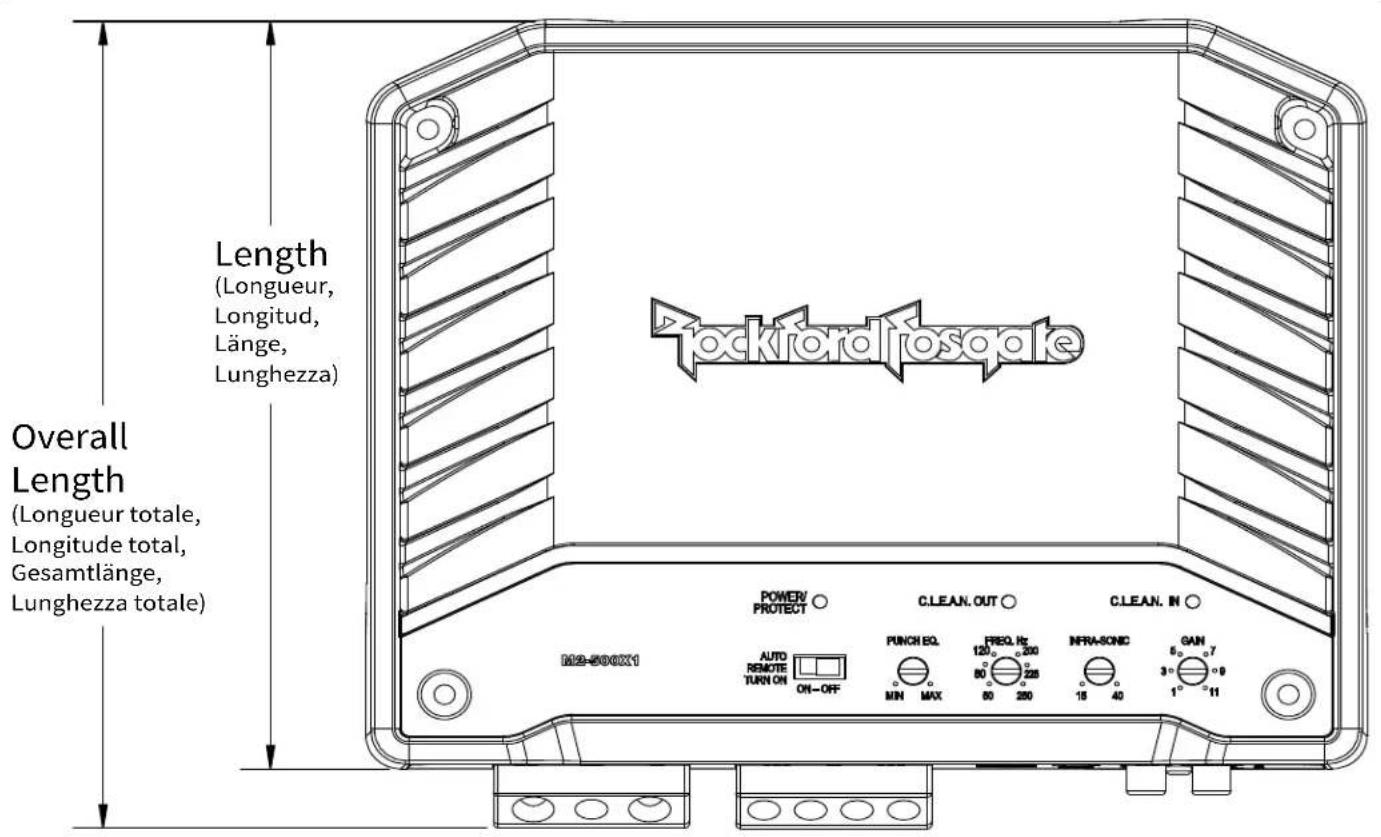
illus.-1.1
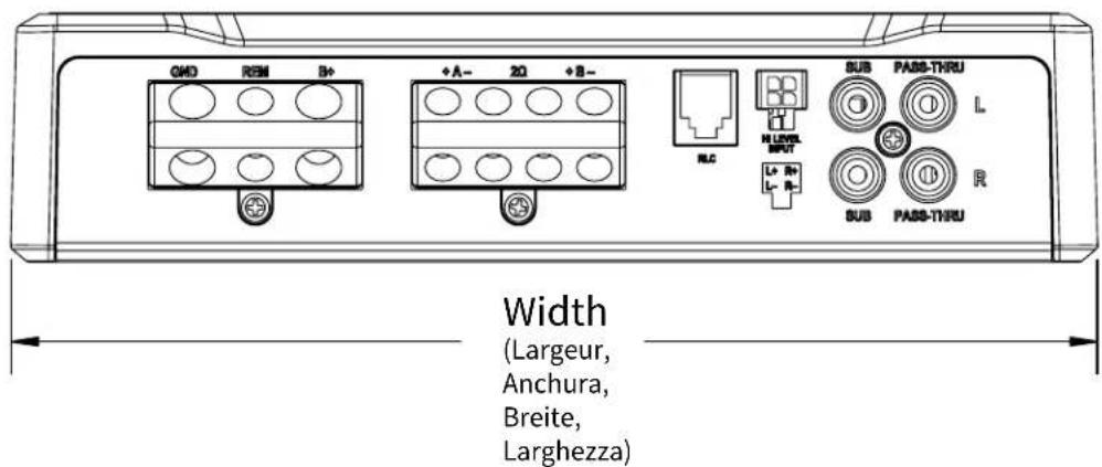
illus.-1.2
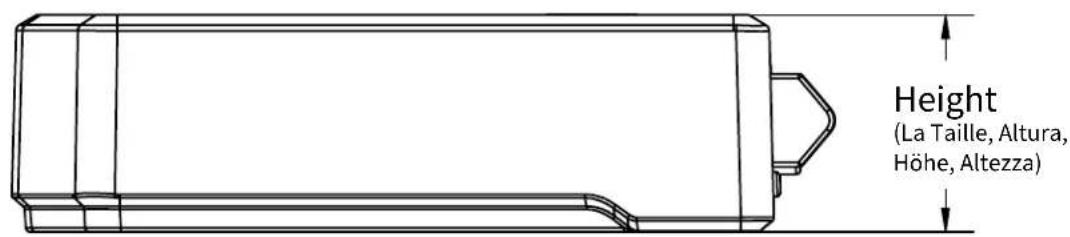
illus.-1.3

natural_image
Technical line drawing of a mechanical component with a cylindrical shaft and mounting base (no text or symbols)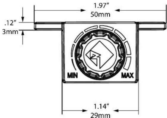
NEW TECHNOLOGIES
C.L.E.A.N. – Calibrated Level Eliminated Audible Noise – Allows for accurate setup of an amplifier's input and output WITHOUT the need of additional measurement devices.
C.L.E.A.N. IN – Indicates when the input into the amplifier starts to distort by lighting up RED.
How does it work – Turn the volume level on the source unit up until the light turns RED, then reduce the volume level until the light turns OFF. This is the maximum level that the source unit should be turned up to in order to provide a distortion free signal into the amplifier.
C.L.E.A.N. OUT – Indicates when the output from the amplifier starts to distort by lighting up RED.
How does it work – Setup should be performed at the maximum level of the source unit determined by the C.L.E.A.N. IN indicator.
Turn the GAIN up until the light turns RED, then turn down the GAIN until the light turns OFF. This is the maximum level that the GAIN should be set to in order to provide a distortion free output from the amplifier.
Auto Remote Turn ON Switch – Utilizes the DC offset of the source units front LEFT speaker to turn the amplifier ON and OFF. Turning the switch to the OFF position requires the connection to the REM input to be connected to a 12 Volt switched accessory circuit using a 1 Amp fuse or the REM output from an aftermarket head unit.
Note: This only applies to high level inputs.
How does it work – DC offset is the 3-6 Volts coming from the source unit's positive speaker lead. This can be tested using a DMM (Digital Multi-Meter) set to DC voltage by connecting the meters Positive lead to the front LEFT positive speaker lead and connecting the negative lead to chassis ground and turning the source unit ON.
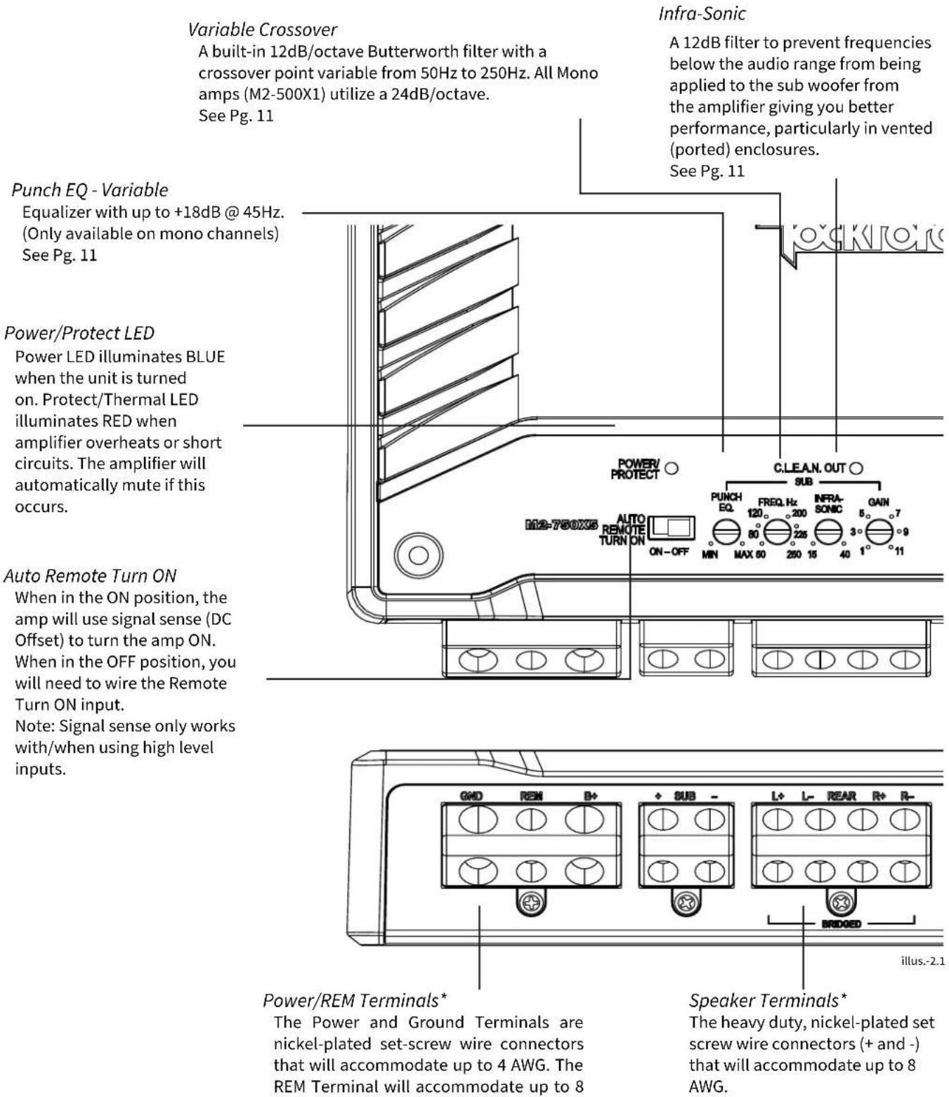
*All terminals use a 3mm Allen wrench that is included with each amp.
Crossover Switch
Selectable switch for Low-Pass (LP) or All Pass (AP) or High-Pass (HP) Note: All mono amps are fixed at LP.
See Pg. 11
Input Switch
Setting the switch to 5, 4 or 2 lets the amp know how many inputs are being used. Match this to the amount of inputs in either hi-level or low-level. See Pg. 11
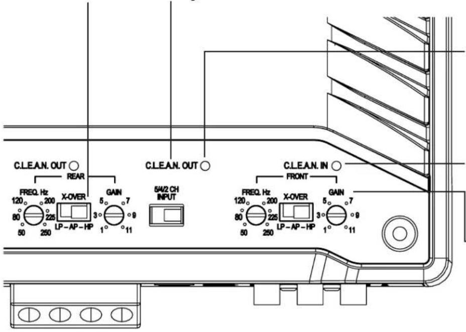
When the RED LED turns ON, the output of the amplifier is distorted. The brighter the LED the more the signal is clipped. See Pg. 11
C.L.E.A.N. Input
When the RED LED turns ON, a distorted signal is being applied to the input of the amplifier. The brighter the LED the more the signal is clipped. See Pg. 11
Gain Control
The gain control is used to match the signal level of the audio source to the input of the amplifier. See Pg. 11
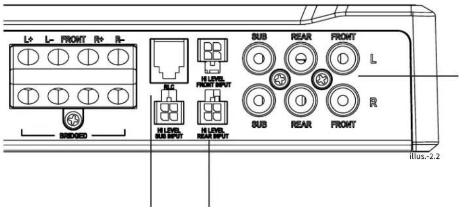
Low Level/ RCA Input/ Pass-Thru Jacks\*\*
The balanced differential RCA Inputs/Pass-Thru Jacks are nickel-plated to resist the signal degradation caused by corrosion. The Pass-Thru(not shown) provides a convenient source for daisy-chaining an additional amplifier without running an extra set of RCA cables from the front of the vehicle to the rear amplifier location.
Note: Pass-Thru not available on M2-750X5.
** Use either High or Low Level input, never both.
Remote Level Control
Remotely control the sub woofer output level of the amplifier. (Only available for mono channels)
High Level Inputs - Optional Inputs\*\*
This allows you to connect your amplifier directly to an OEM head unit without the addition of an LOC (Line Output Converter). See Pg. 10
Contents
- M2 Element Ready™ Amplifier
- Mounting Hardware
- Allen Wrench
- Remote Level Control (only available on amplifiers with mono channels)
Installation Considerations
- Fuse-holder and fuse. (See specifications for fuse rating)
- Volt/Ohm Meter
- Wire strippers
- Wire crimpers
- Wire cutters
• #2 Phillips screwdriver
- Battery post wrench
• 4-pin Molex pig tail connectors
- Test tones available for download at https://rftech.custhelp.com/app/answers/detail/a_id/1126/Scroll to the bottom of the page and download your preferred format.
- Hand held drill w/ assorted bits
• Assorted connectors
- Adequate Length & gauge—Red Power Wire
- Adequate Length—Remote Turn-on Wire (not needed if using Auto Turn ON feature)
- Adequate Length & gauge—Black Grounding Wire
This section focuses on some of the vehicle considerations for installing your new amplifier. Pre-planning your system layout and best wiring routes will save installation time. When deciding on the layout of your new system, be sure that each component will be easily accessible for making adjustments.
If you feel unsure about installing this system yourself, have it installed by a qualified technician.

CAUTION
Before installation, disconnect the battery negative (-) terminal to prevent damage to the unit, fire and/or possible injury.

CAUTION
Before beginning any installation, follow these simple rules:
-
Be sure to carefully read and understand the instructions before attempting to install the unit.
-
For easier assembly, we suggest you run all wires prior to mounting your unit in place.
-
Route all of the RCA cables close together and away from any high current wires.
-
Use high quality Rockford Fosgate connectors for a reliable installation and to minimize signal or power loss.
-
Think before you drill! Be careful not to cut or drill into gas tanks, fuel lines, brake, hydraulic lines, vacuum lines or electrical wiring
when working on any vehicle.
-
Never run wires underneath the vehicle. Running the wires inside the vehicle provides the best protection.
-
Avoid running wires over or through sharp edges. Use rubber or plastic grommets to protect any wires routed through metal, especially the fire wall.
-
ALWAYS protect the battery and electrical system from damage with proper fusing. Install the appropriate fuse holder and fuse on the +12V power wire within 18" (45.7 cm) of the battery terminal.
-
When grounding to the chassis of the vehicle, scrape all paint from the metal to ensure a good, clean ground connection. Grounding connections should be as short as possible and always be connected to metal that is welded to the main body, or chassis of the vehicle. Seat belt bolts should never be used for connecting to ground.
Mounting Locations
To ensure optimal performance, mount the amplifier with at least 1" (25.4mm) of air gap around the amplifier's heat sink to provide proper cooling.
Trunk Mounting
Mounting the amplifier vertically or inverted will provide adequate cooling of the amplifier. Mounting the amplifier on the floor of the trunk will provide the best cooling of the amplifier.
Passenger Compartment Mounting
Mounting the amplifier in the passenger compartment will work as long as you provide a sufficient amount of air for the amplifier to cool itself. If you are going to mount the amplifier under the seat of the vehicle, you must have at least 1" (25.4mm) of air gap around the amplifier's heat sink.

CAUTION
Never mount this unit in the engine compartment. Mounting the unit in the engine compartment will void your warranty.
Battery and Charging
Amplifiers will put an increased load on the vehicle's battery and charging system. We recommend checking your alternator and battery condition to ensure that the electrical system has enough capacity to handle the increased load of your stereo system. Stock electrical systems which are in good condition should be able to handle the extra load of any Prime Series amplifier without problems, although battery and alternator life can be reduced slightly. To maximize the performance of your amplifier, we suggest the use of a heavy duty battery and an energy storage capacitor.
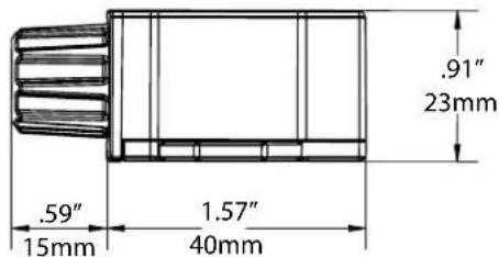
RLC Mounting Options – Utilize the included screws to secure the RLC to the vehicle.
Wiring the System

CAUTION
If you do not feel comfortable with wiring your new unit, please see your local Authorized Rockford Fosgate Dealer for installation.

CAUTION
Before installation, disconnect the battery negative (-) terminal to prevent damage to the unit, fire and/or possible injury.

CAUTION
Avoid running power wires near the low level input cables, antenna, power leads, sensitive equipment or harnesses. The power wires carry substantial current and could induce noise into the audio system.
- Plan the wire routing. Keep RCA cables close together but isolated from the amplifier's power cables and any high power auto accessories, especially electric motors. This is done to prevent noise from radiated electrical fields into the audio signal. When feeding the wires through the fire wall or any metal barrier, protect them with plastic or rubber grommets to prevent short circuits. Leave the wires long at this point to adjust for a precise fit at a later time.
- Prepare the RED wire (power cable) for attachment to the amplifier by stripping 1/2" of insulation from the end of the wire. Insert the bared wire into the B+ terminal and tighten the set screw to secure the cable in place.
NOTE: The B+ cable MUST be fused 18" or less from the vehicle's battery. Install the fuse holder under the hood and ensure connections are water tight.
- Trim the RED wire (power cable) within 18" of the battery and splice in a in-line fuse holder (not supplied). See Specifications for the rating of the fuse to be used. DO NOT install the fuse at this time.
- Strip 1/2" from the battery end of the power cable and crimp an appropriate size ring terminal to the cable. Use the ring terminal to connect to the battery positive terminal.
- Prepare the BLACK wire (Ground cable) for attachment to the amplifier by stripping 1/2" of insulation from the end of the wire. Insert the bare wire into the GROUND terminal and tighten the set screw to secure the cable in place. Prepare the chassis ground by scraping any paint from the metal surface and thoroughly clean the area of all dirt and grease. Strip the other end of the wire and attach a ring connector. Fasten the cable to the chassis using a non-anodized screw and a star washer.
NOTE: Keep the length of the BLACK wire (Ground) as short as possible. Always less than 30".
NOTE: Skip step 6 if you are using Auto Turn ON feature.
- Prepare the Remote turn-on wire for attachment to the amplifier by stripping 1/2" of insulation from the end of the wire. Insert the bared wire into the REMOTE terminal and tighten the set screw to secure the wire in place. Connect the other end of the Remote wire to a switched 12 volt positive source. The switched voltage is usually taken from the source unit's remote amp on lead. If the source unit does not have this output available, the recommended solution is to wire a mechanical switch in line with a 12 volt source to activate the amplifier.
- Securely mount the amplifier to the vehicle or amp rack. Be careful not to mount the amplifier on cardboard or plastic panels. Doing so may enable the screws to pull out from the panel due to road vibration or sudden vehicle stops.
Note: Skip step 8 if using High Level inputs.
- Connect from source signal by plugging the RCA cables into the input jacks at the amplifier.

CAUTION
NOTE: All "ACTIVE" inputs must have RCA jacks connected. Switch in 2CH. Position, "ACTIVE" - Front channel inputs only. Switch in 4CH. Position, "ACTIVE" - All Front and Rear channel inputs. Switch in 5CH position, "ACTIVE" - Sub inputs for sub output. When connecting to the 5-Channel inputs, be sure to route front, rear and sub RCA cables tightly together.
Always ensure power is off or disconnected at the amplifier before connecting RCA cables. Failure to do so may cause damage to the amplifier and/or connected components.
- If using High Level inputs, connect the OEM speaker wires matching the positive and negative. If only using 1 input, be sure to plug it into the front and make sure the input selection switch is set to 2 ch.
- Connect the speakers. Strip the speaker wires 1/2" and insert into the speaker terminal and tighten the set screw to secure into place. Be sure to maintain proper speaker polarity. DO NOT chassis ground any of the speaker leads as unstable operation may result. For mono amps, the two Positive (+) and Negative (−) terminals are provided for installation flexibility. Both terminals are wired in parallel internally. Only one Positive (+) and one Negative (−) terminal is required for a speaker connection.

CAUTION
- Perform a final check of the completed system wiring to ensure that all connections are accurate. Check all power and ground connections for frayed wires and loose connections which could
cause problems. Install in-line fuse near battery connection.
This amplifier is not recommended for impedance loads below 2-Ohm stereo/4-Ohm bridged for the front/rear channels and 2-Ohm for the sub channel.
High Level Inputs
7"
180mm
PIN 2
Connector side
PIN 4
PIN 1
PIN 3
FRONT REAR SUB
| PIN 1 - White | PIN 1 - Green | PIN 1 - Blue |
| PIN 2 - White/Grey | PIN 2 - Green/Black | PIN 2 - Blue/Black |
| PIN 3 - Grey | PIN 3 - Violet | PIN 3 - Brown |
| PIN 4 - Grey/Black | PIN 4 - Violet/Black | PIN 4 - Brown/Black |
LEFT (+) WHITE
LEFT (−) WHITE/BLACK
RIGHT (+) GRAY
RIGHT (−) GRAY/BLACK
LEFT (+) GREEN
LEFT (−) GREEN/BLACK
RIGHT (+) PURPLE
RIGHT (−) PURPLE/BLACK
LEFT (+) BLUE
LEFT (−) BLUE/BLACK
RIGHT (+) BROWN
RIGHT (−) BROWN/BLACK
FRONT
REAR
SUB
Setting the Crossover
Complete the following steps for each channel.
Place the X-OVER switch in the correct position for the speaker type.

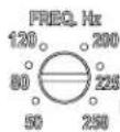
AP – All Pass – This allows all frequencies to pass thru no matter where the FREQ. Hz dial is set.
NOTE: This should only be used if using source unit or DSP with HP/LP filter being used.
HP – High Pass – This allows only frequencies above where the FREQ. Hz dial is set to pass thru (used for mid-range speakers).
LP – Low Pass – This allows only frequencies below where the FREQ. Hz dial is set to pass thru (used for Sub-woofers).
Recommended settings for speakers
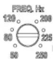
Sub-woofers - 50 - 80 Hz
Mid-range (6X9 - 5.25") 80 - 120 Hz
INFRA-SONIC
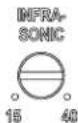
The INFRA-SONIC filter eliminates frequencies below the set point of the dial from going to your subwoofer's. This will help control the woofer, especially in ported/tuned enclosures from overextending its mechanical limits. We recommend setting this between 25 and 30 Hz.
Input Switch
This is used to determine how many inputs are being used (High level or Low level). This allows you to run 1, 2 or 3 sets of inputs to send signal to all the amplifier's outputs.
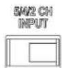
2 CH - This will utilize the FRONT inputs.
4 CH - This utilizes the FRONT and REAR/SUB inputs
5 CH - This utilizes the FRONT, REAR and SUB inputs.
C.L.E.A.N. IN
CLEAN IN ○
NOTE: You can use Music or Test Tones to setup C.L.E.A.N. IN. Before setup, disconnect the speakers from the amplifier outputs. Test tones can be downloaded at https://rftech.custhelp.com/app/answers/detail/a_id/1126/. Scroll to the bottom of the page and download your preferred format.
-
Turn the source unit all the way down and make sure the gains on the amplifier are set to 1. Note: If equipped, make sure the LOUD feature is turned OFF on your source unit.
-
In the source unit, make sure Bass, Treble and Mid are flat.
-
Choose your source to play music (CD, Bluetooth, etc.)
-
Increase the volume on the source unit until the C.L.E.A.N. IN RED LED illuminates.
-
Now reduce the volume level until the RED LED turns off. This will be the max undistorted level of the source unit.
C.L.E.A.N. OUT
CLEAN.OUT ○
Before you adjust the gain:
Make sure that the speakers are not connected to the amplifier outputs.
Make sure the Bass, Treble and Midrange are all set flat and the RLC (if equipped) is turned all the way up/ maximum output position.
Setup should be performed at the maximum level of the source unit that was determined using the C.L.E.A.N. IN.
Using Music to set C.L.E.A.N. OUT - Increase the amplifiers gain until the indicator turns RED, then turn the gain down until the light turns OFF.
Using Test Tones to set C.L.E.A.N. OUT - Increase the amplifiers gain until the indicator turns RED, then turn the gain down until the light turns OFF. Your gain is now set. Use 1KHz/-5dB for midrange drivers and 40Hz/-10dB for subwoofer's.

CAUTION
Avoid setting the Gain to high as this could increase noise and distortion which can damage your speakers.
Punch EQ
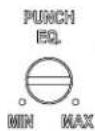
Punch EQ will add a Bass Boost that can be adjusted by the dial from Min (0dB) to Max (18dB). This should be adjusted after all other adjustments are made. If you have already adjusted C.L.E.A.N. OUT you will need to readjust after adjusting Punch EQ.

CAUTION
Over excursion and subsequent damage could occur using high levels of boost.
natural_image
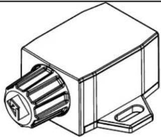
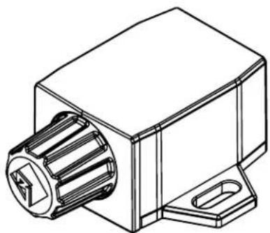
Technical line drawing of a mechanical component with a cylindrical shaft and mounting base (no text or symbols)Remote Level Control (RLC) – When connected, the RLC allows control of the output up and down from the front of the vehicle. (Sub channels only)
Troubleshooting
NOTE: If you are having problems after installation follow the Troubleshooting procedures below.
Check Amplifier for proper connections. Verify that POWER light is on. If POWER light is on skip to Step 3, if not continue.
- Check in-line fuse on battery positive cable. Replace if necessary.
- Check fuse(s) on amplifier. Replace if necessary.
- Verify that Ground connection is connected to clean metal on the vehicle's chassis. Repair/replace if necessary.
- Verify there is 9 to 16 Volts present at the positive battery and remote turn-on cable. Verify quality connections for both cables at amplifier, stereo, and battery/fuse holder. Repair/replace if necessary.
- Make sure the Auto Turn ON Switch is in the correct position. If in the OFF position, make sure your have the REM wire connected. See Step 4 for additional testing.
Protect light is on.
- If the Protect light is on, this is a sign of a possible short in the speaker connections. Check for proper speaker connections and use a volt/ohm meter to check for possible shorts in the speaker wiring. Too low of a speaker impedance may also cause Protect to light.
Check Amplifier for audio output.
- Verify good RCA input connections at stereo and amplifier. Check entire length of cables for kinks, splices, etc. Test RCA inputs for AC volts with stereo on. Repair/replace if necessary.
- Disconnect RCA input from amplifier. Connect RCA input from test stereo directly to amplifier input.
Check Amplifier if you experience Turn-on Pop.
- Disconnect input signal to amplifier and turn amplifier on and off.
- If the noise is eliminated, connect the REMOTE lead of amplifier to source unit with a delay turn-on module.
OR
- Use a different 12 Volt source for REMOTE lead of amplifier.
Check Amplifier if you experience excess Engine Noise.
- Route all signal carrying wires (RCA, Speaker cables) away from power and ground wires.
OR
- Bypass any and all electrical components between the stereo and the amplifier(s). Connect stereo directly to input of amplifier. If noise goes away the unit being bypassed is the cause of the noise.
OR
- Remove existing ground wires for all electrical components. Reground wires to different locations. Verify that grounding location is clean, shiny metal free of paint, rust etc.
OR
- Add secondary ground cable from negative battery terminal to the chassis metal or engine block of vehicle.
OR
- Have alternator and battery load tested by your mechanic. Verify good working order of vehicle electrical system including distributor, spark plugs, spark plug wires, voltage regulator etc.
Sub-woofers - 50 - 80 Hz
Rango medio (6X9 - 5.25 pulg.) 80 - 120 Hz
INFRA-SONIC
Rockford Corporation offers a limited warranty on Rockford Fosgate products on the following terms:
Length of Warranty
POWER Amplifiers – 2 Years
BMW® Direct Fit Speakers – 2 Years
PUNCH® & PRIME® Amplifiers – 1 Year
Speakers, Signal Processors, Accessories and Capacitors – 1 Year
All marine, motorcycle, motorsport products - 2 Years
Any Factory Refurbished Product – 90 Days (receipt required)
What is Covered
This warranty applies only to Rockford Fosgate products sold to consumers by authorized Rockford Fosgate dealers in the United States of America. Products purchased by consumers from an Authorized Rockford Fosgate Dealer in another country are covered only by that country's Distributor and not by Rockford Corporation.
Who is Covered
This warranty covers only the original purchaser of Rockford product purchased from an authorized Rockford Fosgate dealer in the United States. In order to receive service, the purchaser must provide Rockford with a copy of the receipt stating the customer name, dealer name, product purchased and date of purchase.
Products found to be defective during the warranty period will be repaired or replaced (with a product deemed to be equivalent) at Rockford's discretion.
What is Not Covered
- Damage caused by accident, abuse, improper installation, operations, theft, water (on non-Element Ready products).
- Any cost or expense related to the removal or reinstallation of product.
- Service performed by anyone other than Rockford or an authorized Rockford Fosgate service center.
- Any product which has had the serial number defaced, altered, or removed.
- Subsequent damage to other components.
- Any product purchased outside the U.S.
- Any product not purchased from an authorized Rockford Fosgate dealer. Refer to rockfordfosgate.com dealer locator for more detail.
Limit on Implied Warranties
Any implied warranties including warranties of fitness for use and merchantability are limited in duration to the period of the express warranty set forth above. Some states do not allow limitations on the length of an implied warranty, so this limitation may not apply. No person is authorized to assume for Rockford Fosgate any other liability in connection with the sale of the product.
How to Obtain Service
Please call 1-800-669-9899 for Rockford Customer Service. You must obtain an RA# (Return Authorization number) to return any product to Rockford Fosgate. You are responsible for shipment of product to Rockford.
EU Warranty
This product meets the current EU warranty requirements, see your Authorized dealer for details.
- Table of Contents
- PRACTICE SAFE SOUND
- PRATIQUEZ UNE ÉCOUTE SANS RISQUES
- NEW TECHNOLOGIES
- Crossover Switch
- Input Switch
- C.L.E.A.N. Input
- Gain Control
- Low Level/ RCA Input/ Pass-Thru Jacks\*\*
- Remote Level Control
- High Level Inputs - Optional Inputs\*\*
- Contents
- Installation Considerations
- CAUTION
- Mounting Locations
- Trunk Mounting
- Passenger Compartment Mounting
- Battery and Charging
- Wiring the System
- High Level Inputs
- Setting the Crossover
- INFRA-SONIC
- C.L.E.A.N. IN
- C.L.E.A.N. OUT
- Punch EQ
- Troubleshooting
- Protect light is on.
- Check Amplifier for audio output.
- Check Amplifier if you experience Turn-on Pop.
- Check Amplifier if you experience excess Engine Noise.
- Rockford Corporation offers a limited warranty on Rockford Fosgate products on the following terms:
Brand : Rockford Fosgate
Model : M2-750X5
Category : Receiver