
Q-Class 41QSS654 - Loudspeaker KICKER - Free user manual and instructions
Find the device manual for free Q-Class 41QSS654 KICKER in PDF.


| Product type | 2-way component speaker |
| Model | Q-Class 41QSS654 (QSS65) |
| Brand | KICKER |
| Peak power handling | 180 watts |
| Continuous power handling | 90 watts |
| Sensitivity (1W/1m) | 86 dB |
| Frequency response | 50 Hz - 22 kHz |
| Nominal impedance | 4 Ω |
| Woofer diameter | 6-1/2" (160 mm) |
| Tweeter diameter | 1-3/16" (30 mm) |
| Tweeter dome material | Tetoron® (Dupont) |
| Woofer mounting diameter | 5-1/16" (129 mm) |
| Woofer mounting depth | 2.5" (63.5 mm) |
| Tweeter mounting diameter | 1-13/16" (46 mm) |
| Tweeter mounting depth | 1-1/8" (29 mm) |
| High-pass | 24 dB/octave at 2800 Hz |
| Low-pass | 12 dB/octave at 2800 Hz |
| Tweeter attenuation | 0, +3, +6 dB (jumper selectable) |
| Installation configurations | Coaxial, separate, bi-amplified |
| Maintenance | Clean with a dry cloth; avoid exposure to water |
| Safety | High sound levels can damage hearing; adjust volume with caution |
| Warranty | International warranty - contact authorized dealer |
| Spare parts and repairability | Contact authorized KICKER dealer |
Frequently Asked Questions - Q-Class 41QSS654 KICKER
User questions about Q-Class 41QSS654 KICKER
0 question about this device. Answer the ones you know or ask your own.
Ask a new question about this device
Download the instructions for your Loudspeaker in PDF format for free! Find your manual Q-Class 41QSS654 - KICKER and take your electronic device back in hand. On this page are published all the documents necessary for the use of your device. Q-Class 41QSS654 by KICKER.
USER MANUAL Q-Class 41QSS654 KICKER
Owner's Manual | English
The KICKER QSS-series component systems offer unmatched audio fi delity for vehicle applications. Whether you're confi guring the ultimate multi-speaker and subwoofer surround system or simply upgrading from dull, lifeless factory speakers, the QSS component systems deliver the most pleasing full-range sound on the market today! Key features of our highest-end component systems include:
Crossover
Zobel Impedance correction to flatten impedance network
Mylar capacitors and audiophile-grade air core inductors
Bi-amplification capable
Asymmetrical circuit design
Brushed aluminum base heat sink
Balanced sweeler alteration
Heatsinked resistors for increased power handling
Dedicated attenuation jumpers (0, +3 or +6 dB) for a clean connection with less resistance
Illuminated tweeter protection
Woofer
Revolutionary surround design maximizes cone area, maintains standard cutout size
Copper shorting ring on the pole piece to reduce distortion
Polished back plate
Tri-tech cone design
Aluminum phase plug
Copper-clad aluminum coil wire
Ultra-durable Spiral Tinse leads, woven through the duo-wave solder
Strongest available cast aluminum basket, increasing magnetism
Nickel-plated, spring-loaded terminals
Tweeter
Pressed polyfi I inserted behind the dome for acoustic dampening
Dual Neodymium magnets with tuning vent
Dupont Teteron composite dome
Open wire mesh-grill
Sealed and tuned chamber
Copper-clad aluminum coil wire
Acoustic cavity coupled to magnet reduces internal roll motions
Enclosure volume allows for lower frequencies, better off-axis response
Extended Tweeter post
PERFORMANCE
Model QSS65 QSS67
Wooler [n, mm] 6-1/2, 180 6-3/4, 165
Tweeler [in,mm] 1-3/16, 30 1-3/16, 30
Dome Material Teloron® Teloron®
Rated Impedance [Ω] 4 4
Peak Power Handling [Watts] 180 200
Continuous Power Handling [Watts RMS] 90 100
Sensitivity [1W, 1m] 86dB 87dB
Frequency Response [Hz] 50-22k 40-22k
Woofer Mounting Hole Diameter [in, mm] 5-1/16, 129 5-7/16, 138
Woofer Bottom Mount Depth [in, mm] 2.5, 63.5 2.5, 63.5
Flush Mount Tweeter Hole Diameter [in,mm] 1-13/16, 46 1-13/16, 46
Flush Mount Tweeter Depth [n,mm] 1-1/8,29 1-1/8,29
High Pass [dB], at Frequency [Hz] 24, 2800 24, 2800
Low Pass [dB], at Frequency [Hz] 12, 2800 12, 2800
High Frequency Output Attenuation [dB] 0, +3, +6 0, +3, +6
CONFIGURATION
Before mounting and wiring the QSS component system, determine which configuration you will use for the speakers and crossover.
QSS Speaker
Confi gurations
ADVANTAGES CONSIDERATIONS
| Coaxial great for space-limited applications or when separate tweeter mounting is not possible | high frequencies may not be as prominent | tweeter output may need to be increased at crossover |
| Separates optimal sound quality and improved sonic imaging (with proper tweeter mounting) | trickier install | vehicle must have a good tweeter mounting location |
| QSS Crossover Confi gurations ADVANTAGES CONSIDERATIONS | |
| Conventional 2-way easy install | ideal when available amplifi er channels are limited | audio fi delity not quite as high as bi-amplifi ed confi guration |
| Bi-amplifi ed optimal sound quality; more effi cient usage of amplifi er power | requires at least 4 amplifi er channels | slightly trickier install |
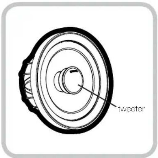
Coaxial Confi guration
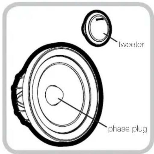
Separates Conf i guration
The QSS component system comes packaged in a separates configuration.
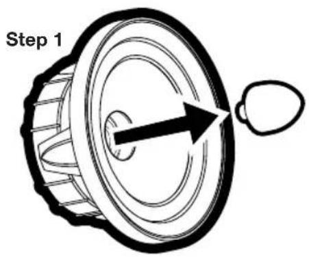
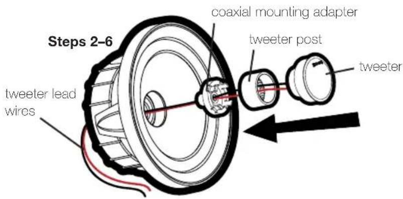
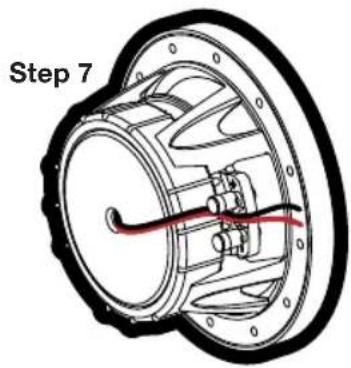
To use a coaxial configuration, see Fig. 1 and follow these steps:
- Unscrew and remove the aluminum phase plug from the center of the woofer.
- Screw the coaxial mounting adapter into the woofer in place of the phase plug.
- Screw the tweeter into the tweeter post.
- Thread the tweeter's lead wires through the center of the woofer.
- Snap the tweeter post onto the coaxial mounting adapter.
- Rotate the tweeter clockwise for the most appealing position.
- Secure the tweeter's lead wires using the clip on the underside of the woofer.
Fig. 1
Confi guring the QSS for Coaxial Operation
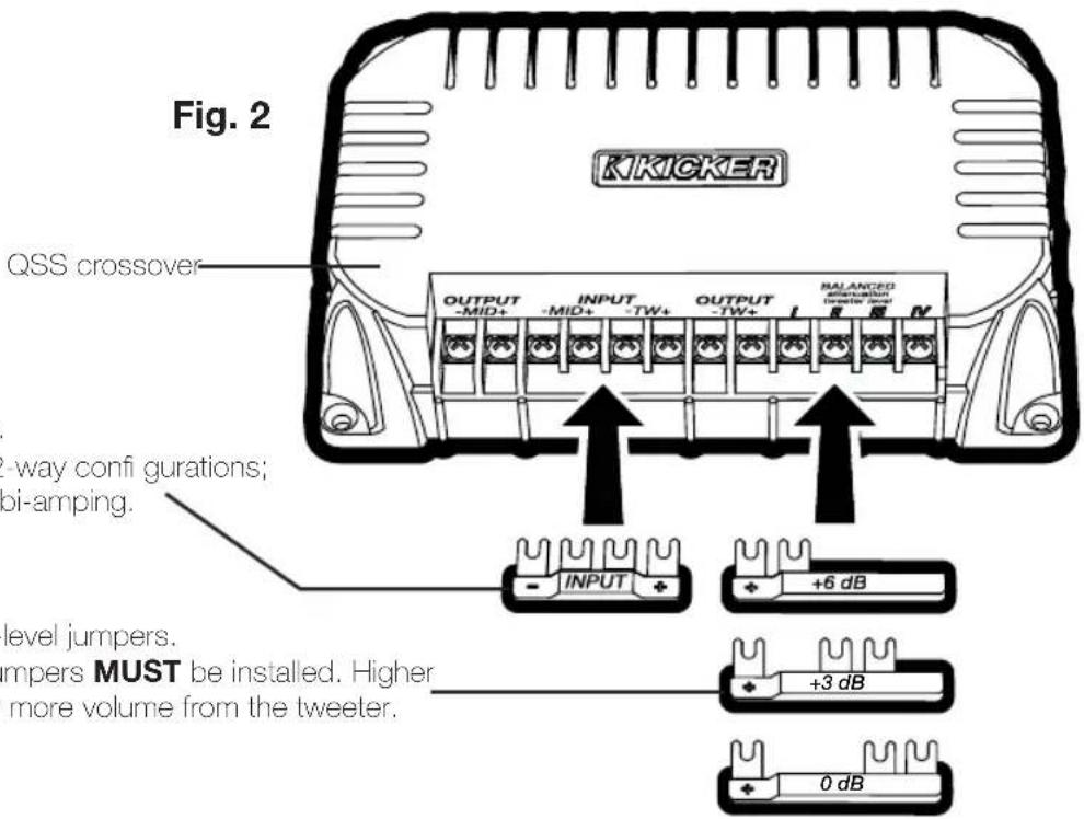
INPUT jumper.
Install only for 2-way configurations; do not install if bi-amping.
tweeter output-level jumpers.
One of these jumpers MUST be installed. Higher numbers mean more volume from the tweeter.
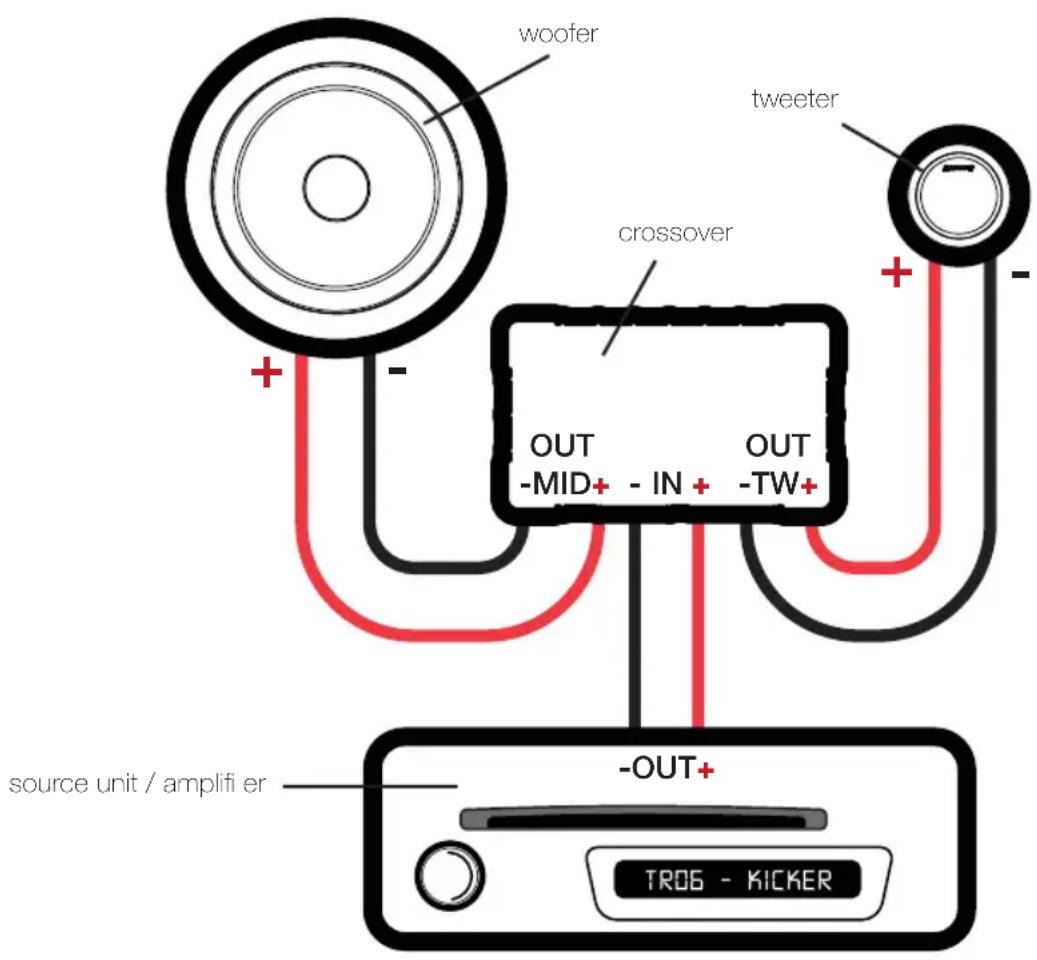
The KICKER QSS crossover can be configured as a conventional 2-way crossover by installing the included INPUT jumper into the -MID + -TW + input terminals as shown in Fig. 2. In this configuration, the amplified signal from your source unit or amplifier should be wired to the + and - terminals indicated on the INPUT jumper.
The QSS crossover can also be configured for bi-amp wiring by removing (or simply not installing) the INPUT jumper. To use the bi-amp configuration, you must connect two amplified signals to each crossover (you will need at least four amplifiers channels). Install one of the included tweeter output-level jumpers (0 dB, +3 dB, or +6 dB) to adjust the tweeter output level. Installing jumpers with higher numbers will result in more volume from the tweeter.
WIRING
We recommend using 16 gauge (or larger) wire. The QSS components are rated at 4 ohms and work with any source unit or amplifier designed to operate at a 4 ohm load. Make sure your source unit or amplifier is rated for 4 ohm operation.
Crossover in 2-way configuration | One component set per channel
- At least two amplifi er channels are needed for stereo operation (only one channel is shown)
Crossover in bi-amp confi guration Two channels per component set
- At least four amplifier channels are needed for stereo operation (only two channels are shown)
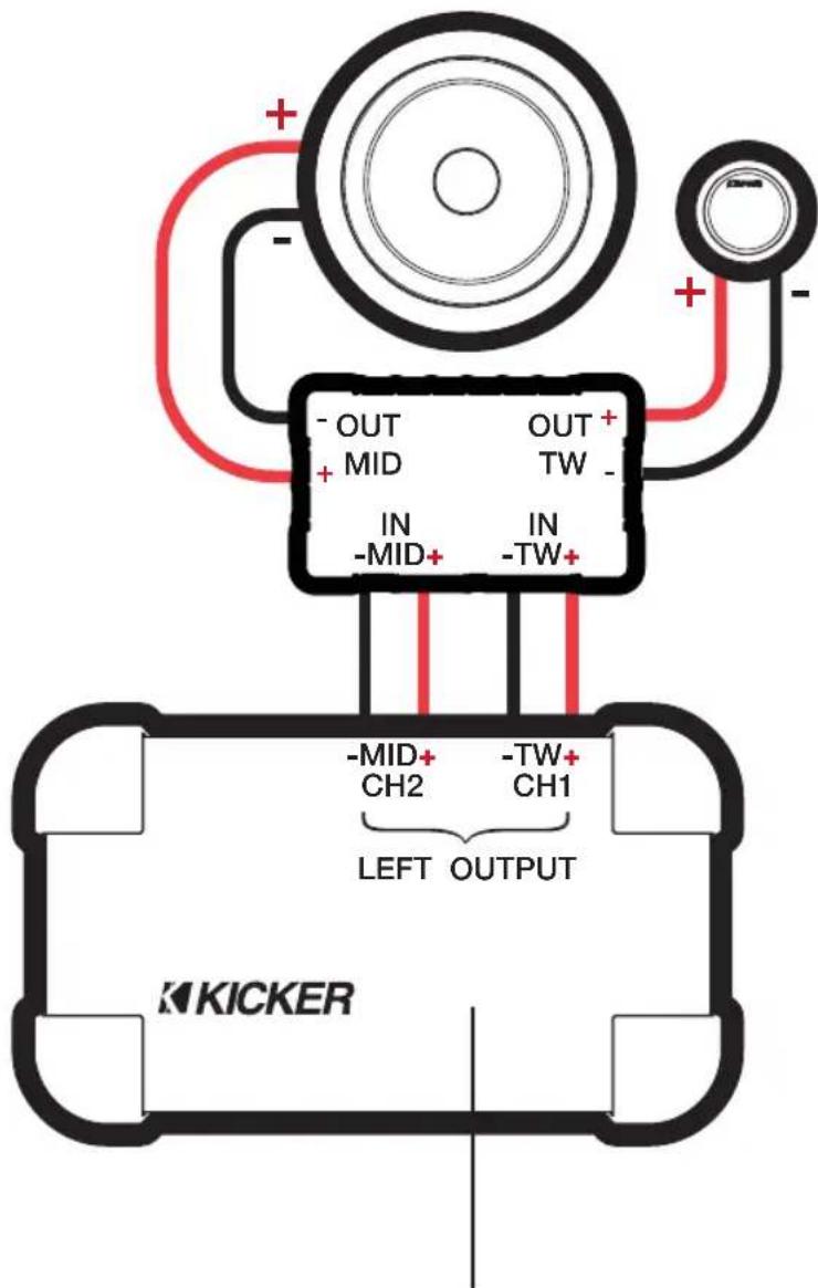
amplifi er / source unit (must have at least four channels)
Pro Tip: Looking for the next step in audio performance from your QSS components? Upgrade to a KICKER IQ or KX 4 or 5-channel amplifier for each QSS component system you have installed to take full advantage of the QSS's bi-amping capabilities. With a dedicated amplifier channel for each tweeter and each midrange driver, you'll have a more efficient system that will deliver a clearer soundstage and an increasingly dramatic dynamic response. In other words, your music will be more expansive and captivating.
WOOFER MOUNTING
The KICKER QSS components are designed for free-air applications and do not require a sealed enclosure for optimum performance. It is important to isolate the sound coming from the front of the speaker from the sound radiating from the back of the speaker. This is most easily accomplished by mounting the speakers in a vehicle's factory locations or in a location with a semi-isolated rear chamber (like the rear deck of a car behind the rear seats).
If you are replacing factory speakers in their original locations, you may have to enlarge the speaker cut-outs and pre-drill new screw holes using a 7/64" (2.5mm) bit. Custom mounting locations will require more preparation and work. Make sure that the speaker will not interfere with trunk and door opening and closing mechanisms and that the enclosed screws will not puncture the fuel tank, puncture wiring, or interfere with any other mechanical parts on the underside of the mounting surface. Cycle the windows all the way down and up.
If the speaker cut-out locations require you to cut metal, avoid structural metal and braces. Mount the speaker to the vehicle as outlined in Fig. 3.
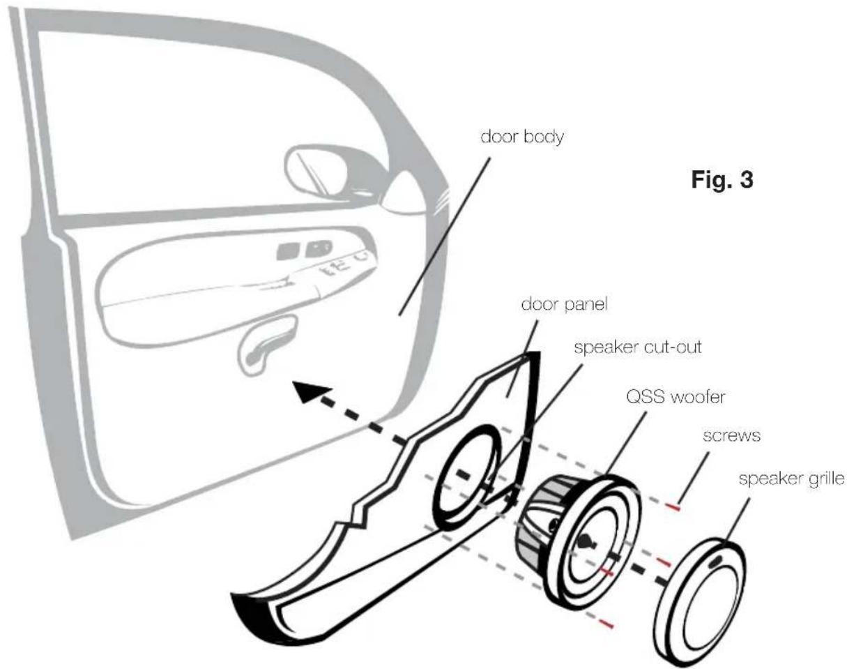
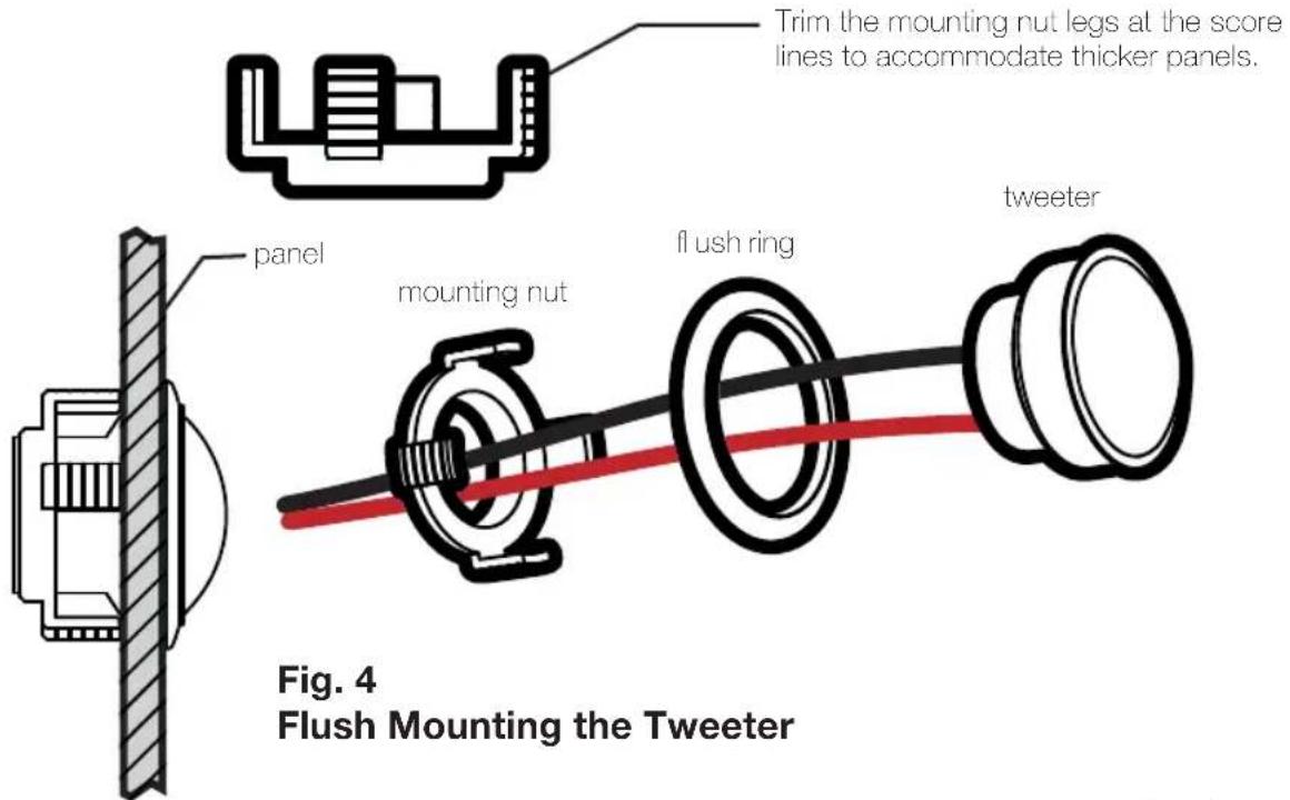
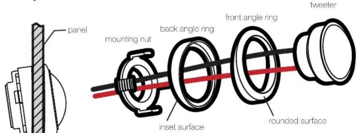
Fig. 5 Angle Mounting the Tweeter
TWEETER MOUNTING
The tweeter can be mounted one of three ways: flush, angled, and coaxial mounting. For flush mounting applications, see Fig. 4. Choose a flat location on the panel with space behind the panel to allow room for the mounting nut, motor structure, and tweeter post. After checking the clearances, cut a 1-13/16" (46mm) diameter mounting hole in the panel. Position the mounting nut behind the panel. Feed the wire through the optional flush ring, the hole in the panel, and the mounting nut. Mount the tweeter by screwing the mounting nut onto the tweeter.
For angled mounting applications choose a fl at location on the panel with space behind the panel to allow room for the mounting nut, motor structure, tweeter post, and back angle ring. After checking the clearances, cut a 1-13/16" (46mm) diameter mounting hole in the panel. Place the front angle ring in front of the panel. Then place the wire and tweeter through the front angle ring and into the panel. Next, place the wire through the back angle ring, place the back angle ring over the rear of the tweeter, and line-up the narrow part of the front angle ring for the preferred angle of operation. Place the wire through the mounting nut and loosely tighten the mounting nut around the tweeter. Rotate all the parts in unison until the tweeter is angled in the desired direction. Secure the assembly by tightening the mounting nut. See
Fig. 5
8
CROSSOVER MOUNTING
Mount the crossover in a location that is easy to access for wiring and tweeter output level adjustment. Make sure that the crossover will not be exposed to water. The bottom of the car door is not a good location. If you must mount the crossover in the car door, exercise caution as water can accumulate in the bottom of the door. Keep the crossover high in the door and shielded from water.
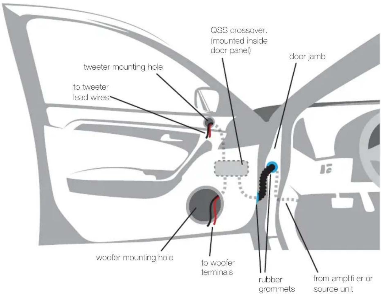
The speaker wire should be kept away from sharp edges and avoid the possibility of getting pinched by the door. An existing grommet in the door jamb is the ideal place to run the speaker wire. If the factory hole and grommet do not exist or are inaccessible, you must drill a hole to run the speaker wire through the door jamb. Be careful not to drill into other wiring or existing door mechanisms. Any time a wire is run through a hole, it is necessary to insert a rubber or plastic grommet to protect the wire from damage.
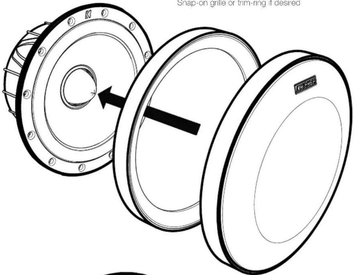
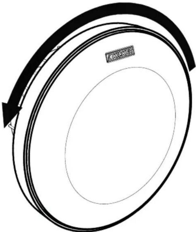
GRILLE MOUNTING
Snap-on grille or trim-ring if desired
natural_image
Circular diagram with concentric rings and an arrow indicating rotation, no text or symbols presentRotate grille/trim-ring counterclockwise to remove
Note: All specifications and performance figures are subject to change. Please visit www.kicker.com for the most current information. To get the best performance from your new KICKER speakers, we recommend using genuine KICKER accessories and wiring. Please allow two weeks of break-in time for the speakers to reach optimum performance.
ACOUSTICS LIMITED WARRANTY
When purchased from an Authorized KICKER Dealer, KICKER warrants this product to be free from defects in material and workmanship under normal use for a period of ONE (1) YEAR from date of original purchase. If this product is identified as "Refurbished" or "B Goods", the warranty is limited to a period of THREE (3) MONTHS from date of original purchase. In all cases you must have the original receipt. Should service be necessary under this warranty for any reason due to manufacturing defect or malfunction during the warranty period, KICKER will repair or replace (at its discretion) the defective merchandise with equivalent merchandise. Warranty replacements may have cosmetic scratches and blemishes. Discontinued products may be replaced with more current equivalent products. This warranty is valid only for the original purchaser and is not extended to owners of the product subsequent to the original purchaser. Any applicable implied warranties are limited in duration to a period of the express warranty as provided herein beginning with the date of the original purchase at retail, and no warranties, whether express or implied, shall apply to this product thereafter. Some states do not allow limitations on implied warranties; therefore, these exclusions may not apply to you. This warranty gives you specific legal rights; however you may have other rights that vary from state to state.
WHAT TO DO IF YOU NEED WARRANTY OR SERVICE:
Defective merchandise should be returned to your local Authorized Stillwater Designs (KICKER) Dealer for warranty service. Assistance in locating an Authorized Dealer can be found at www.kicker.com or by contacting Stillwater Designs directly. You can confirm that a dealer is authorized by asking to see a current authorized dealer window decal.
If it becomes necessary for you to return defective merchandise directly to Stillwater Designs (KICKER), call the KICKER Customer Service Department at (405) 624-8510 for a Return Merchandise Authorization (RMA) number. Package only the defective items in a package that will prevent shipping damage, and return to:
Stillwater Designs, 3100 North Husband St, Stillwater, OK 74075
The RMA number must be clearly marked on the outside of the package. Please return only defective component systems. The return of functioning items increases your return freight charges. Non-defective items will be returned freightcollect to you. For example, if a subwoofer is defective, only return the defective subwoofer, not the entire enclosure. Include a copy of the original receipt with the purchase date clearly visible, and a "proof-of-purchase" statement listing the Customer's name, Dealer's name and invoice number, and product purchased. Warranty expiration on items without proof-of-purchase will be determined from the type of sale and manufacturing date code. Freight must be prepaid; items sent freight-collect, or COD, will be refused.
WHAT IS NOT COVERED?
This warranty is valid only if the product is used for the purpose for which it was designed. It does not cover:
o Damage due to improper installation
o Subsequent damage to other components
o Damage caused by exposure to moisture, excessive heat, chemical cleaners, and/or UV radiation
o Damage through negligence, misuse, accident or abuse. Repeated returns for the same damage may be considered abuse
o Any cost or expense related to the removal or reinstallation of product
o Speakers damaged due to amplifier clipping or distortion
o Items previously repaired or modified by any unauthorized repair facility
o Return shipping on non-defective items
o Products with tampered or missing barcode labels
o Products with tampered or missing serial numbers
o Products returned without a Return Merchandise Authorization (RMA) number
o Products purchased from an UNAUTHORIZED dealer
o Freight Damage
o The cost of shipping product to KICKER
o Service performed by anyone other than KICKER
HOW LONG WILL IT TAKE?
KICKER strives to maintain a goal of one-week service for all acoustics (subwoofers, midrange drivers, tweeters, crossovers, etc) returns. Delays may be incurred if lack of replacement inventory or parts is encountered. Failure to follow these steps may void your warranty. Any questions can be directed to the KICKER Customer Service Department at (405) 624-8510. Contact your International KICKER dealer or distributor concerning specific procedures for your country's warranty policies.
stillwaterdesigns
P.O. Box 459 • Stillwater, Oklahoma 74076 • USA • (405) 624–8510
natural_image
Circular diagram with concentric rings and an arrow indicating rotation, no text or symbols presentTransfert (crossover)
Contact your International Kicker dealer or distributor concerning specific procedures for your country's warranty policies.
WARNING: KICKER products are capable of producing sound levels that can permanently damage your hearing! Turning up a system to a level that has audible distortion is more damaging to your ears than listening to an undistorted system at the same volume level. The threshold of pain is always an indicator that the sound level is too loud and may permanently damage your hearing. Please use common sense when controlling volume.
©2013 Stillwater Designs
- Crossover
- Woofer
- Tweeter
- PERFORMANCE
- Model QSS65 QSS67
- CONFIGURATION
- WIRING
- Crossover in 2-way configuration | One component set per channel
- Crossover in bi-amp confi guration Two channels per component set
- WOOFER MOUNTING
- TWEETER MOUNTING
- CROSSOVER MOUNTING
- GRILLE MOUNTING
- ACOUSTICS LIMITED WARRANTY
- WHAT TO DO IF YOU NEED WARRANTY OR SERVICE:
- Stillwater Designs, 3100 North Husband St, Stillwater, OK 74075
- WHAT IS NOT COVERED?
- HOW LONG WILL IT TAKE?
- stillwaterdesigns
Brand : KICKER
Model : Q-Class 41QSS654
Category : Loudspeaker