
C 10RA2 - Saw HITACHI - Free user manual and instructions
Find the device manual for free C 10RA2 HITACHI in PDF.


| Product Type | Table Saw |
| Brand | Hitachi |
| Model | C 10RA2 |
| Power Source | Single-phase alternating current 115 V, 60 Hz, 15 A |
| Motor | Series commutator motor |
| No-load speed | 5000 rpm |
| Blade diameter | 255 mm (10 inches) |
| Blade arbor diameter | 15.9 mm (5/8 inch) |
| Max. cutting depth at 90° | 76.2 mm (3 inches) |
| Max. cutting depth at 45° | 63.5 mm (2-1/2 inches) |
| Net weight | 29 kg (64 lbs) |
| Cord length | 2 m (6.6 ft) |
| Grounding | Yes, 3-conductor plug and cord |
| Compatible materials | Wood (hard or soft) |
| Main functions | Ripping, crosscutting, miter cutting, bevel cutting (45°), dado cutting (with accessory), compound miter cutting |
| Maintenance and cleaning | Clean sawdust regularly, inspect carbon brushes every 50h, grease moving parts once a month, check blade guard operation |
| Safety | Blade guard, riving knife, anti-kickback pawls, switch with safety key, overload protection device |
| Spare parts and repairability | Hitachi approved spare parts, repairs exclusively by an authorized service center |
| Standard accessories | TCT blade 255 mm, positioning brackets (4), wrench, hex wrench, dust extraction elbow |
| Optional accessories | Dado insert, push stick, saw table stand |
Frequently Asked Questions - C 10RA2 HITACHI
User questions about C 10RA2 HITACHI
0 question about this device. Answer the ones you know or ask your own.
Ask a new question about this device
Download the instructions for your Saw in PDF format for free! Find your manual C 10RA2 - HITACHI and take your electronic device back in hand. On this page are published all the documents necessary for the use of your device. C 10RA2 by HITACHI.
USER MANUAL C 10RA2 HITACHI
natural_image
Line drawing of a Hitachi C10RA2 machine with no visible text or symbols on the device itselfINSTRUCTION MANUAL AND SAFETY INSTRUCTIONS
WARNING
Improper and unsafe use of this power tool can result in death or serious bodily injury! This manual contains important information about product safety. Please read and understand this manual before operating the power tool. Please keep this manual available for others before they use the power tool.
MODE D'EMPLOI ET INSTRUCTIONS DE SECURITE
⚠ AVERTISSEMENT
IMPORTANT INFORMATION ....3
MEANINGS OF SIGNAL WORDS ....3
SAFETY
IMPORTANT SAFETY INSTRUCTIONS FOR USING
ALL POWER TOOLS ....3
REPLACEMENT PARTS 6
USE PROPER EXTENSION CORD 6
GROUNDING INSTRUCTIONS .....7
PRACTICAL APPLICATIONS ....18
SAW BLADE MOUNTING AND DISMOUNTING ..25
MAINTENANCE AND INSPECTION 25
SERVICE AND REPAIRS 27
PARTS LIST 81
TABLE DES MATIERES
Français
Page
INFORMATIONS IMPORTANTES ....28
SIGNIFICATION DES MOTS D'AVERTISSEMENT ... 28
SÉCURITÉ
CONSIGNES DE SÉCURITÉ RELATIVES AUX
OUTILS ÉLECTRIQUES. 28
PIECES DE RECHANGE ....32
UTILISATION D'UN CORDON DE RALLONGE .....32
INSTRUCTIONS DE MISE À LA MASSE ....33
UTILISATION ET ENTRETIEN
NOM DES PIÈCES ....34
SPÉCIFICATIONS ....35
ACCESSOIRES 35
ACCESSOIRES STANDARD ....35
ACCESSOIRES EN OPTION ....36
Page
APPLICATIONS 36
DÉBALLAGE 36
PRÉPARATION AVANT L'UTILISATION ....37
MÉTHODES DE MONTAGE ....38
RÉGLAGE 40
Read and understand all of the operating instructions, safety precautions and warnings in the Manual before operating or maintaining this power tool.
Most accidents that result from tool operation and maintenance are caused by the failure to observe basic safety rules or precautions. An accident can often be avoided by recognizing a potentially hazardous situation before it occurs and by observing appropriate safety procedures.
Basic safety precautions are outlined in the SAFETY section of this manual and in the sections which contain the operation and maintenance instructions.
Hazards that must be avoided to prevent bodily injury or machine damage are identified by WARNINGS on the tool and in this Manual.
Never use this tool in a manner that has not been specifically recommended by HITACHI, unless you first confirm that the planned use will be safe for you and others.
MEANINGS OF SIGNAL WORDS
⚠ WARNING: indicates a potentially hazardous situation which, if ignored, could result in serious personal injury.
⚠️ CAUTION: indicates a hazardous situation which, if ignored, could result in a moderate personal injury, or could cause machine damage.
NOTE emphasizes essential information.
SAFETY
IMPORTANT SAFETY INSTRUCTIONS FOR USING ALL POWER TOOLS
READ ALL OF THE WARNINGS AND OPERATING INSTRUCTIONS IN THIS NAMUAL BEFORE OPERATING OR MAINTAINING THIS TOOL:
⚠ WARNING: When using this electric tool, take all necessary precautions to minimize the risk of electric shock or other personal injury. In particular, always comply with the following safety rules:
- ALWAYS KEEP GUARDS IN PLACE and in working order.
- ALWAYS REMOVE ADJUSTING KEYS AND WRENCHES BEFORE STARITING TOOL.
Always confirm that all keys and adjusting wrenches have been removed from the tool before it is turned on. - ALWAYS KEEP WORK AREA CLEAN. Avoid injuries by not cluttering the work areas and work benches.
- NEVER USE TOOL IN HAZARDOUS ENVIRONMENTS. Never use the power tool in damp or wet places and never expose it to rain. Always keep the work area well lighted.
- NEVER PERMIT CHILDREN OR OTHERS TO LOITER NEAR THE WORK AREA. Keep all people (especially children) away from the work area. Always unplug unattended tools and keep the work place tamper-proof by installing locks on the doors and on the master switches. Always remove the safety key from the switch and store it in a secure place, when the tool is not in use.
- NEVER FORCE THE TOOL. It will do the job better and more safely if it is operated at the rate for which it was designed.
- ALWAYS USE THE RIGHT TOOLS. Never force a tool or an attachment to do a job for which it was not designed.
-
ALWAYS WEAR PROPER APPAREL WHEN WORKING WITH THE TOOL. Never wear loose clothing, gloves, neckties, rings, bracelets or other jewelry which may get caught in the moving parts. Always wear non-slip footwear, preferably with steel toes. Wear protective hair covering to contain long hair.
-
ALWAYS USE EYE PROTECTION WHEN WORKING WITH THE TOOL TO PREVENT EYE INJURY. Ordinary eyeglasses do not provide adequate protection because they have only impact resistant lenses, they are NOT safety glasses. Also, use a face mask for additional safety and wear a dust mask if the cutting operation produces dust.
- ALWAYS SECURE THE WORKPIECE TO THE FENCE OR THE TABLE. Use clamps or a vise to hold the workpiece in place. It is safer than using your hand and it frees both hands to operate the tool.
- NEVER OVERREACH. Always keep proper footing and balance when working with the tool.
- ALWAYS MAINTAIN TOOLS WITH CARE. Always keep tools sharp and clean for the best and safest performance. Always follow instructions for lubricating the tool and for changing accessories.
- ALWAYS DISCONNECT THE TOOL before servicing and before changing blades or other accessories.
- NEVER RISK UNINTENTIONAL STARTING WHEN PLUGGING IN THE TOOL. Always confirm that the switch is in the OFF position before inserting the power plug into the receptacle.
- ALWAYS USE RECOMMENDED ACCESSORIES ONLY WHEN OPERATING THIS TOOL. Consult this instruction manual for descriptions of recommended accessories. To avoid personal injuries, use only recommended accessories in conjunction with this tool.
- NEVER STAND ON THE TOOL. Serious injury could occur if the tool is tipped or if unintentional contact with the saw blade is made.
- ALWAYS CHECK FOR DAMAGED PARTS BEFORE USING THE TOOL. Always check the guard and all other components for damage before using the tool to assure that they will function properly. Check all moving parts for proper alignment, freedom from binding and other conditions that might affect proper operation. Always repair or replace any damaged guards or other damaged components before using the tool.
- ALWAYS CONFIRM THE ROTATION DIRECTION OF THE BLADE BEFORE USING THE TOOL. Always feed work into the tool against the rotation direction of the blade in order to prevent possible injury.
- NEVER LEAVE THE TOOL RUNNING WHILE UNATTENDED. TURN POWER OFF. Do not leave tool until it comes to a complete stop. Always turn the power off when the tool is not in use. Always unplug the power cord when the tool is not in use.
- This tool was not designed to be used for mass-production applications and should not be used in mass-production environments.
- When servicing this tool, use only authorized replacement parts.
- Apply 115 volts AC only to this tool. Applying the wrong voltage or applying DC power can cause the POWER TOOL to operate improperly and cause serious personal injury or damage to the tool.
- PROPER GROUNDING. This tool should be grounded while in use to protect the operator from electric shock.
Specific Safety Rules for Use of this Power Tool
⚠ WARNING: The following specific operating instructions must be observed when using this POWER TOOL in order to avoid injury:
DO's
ALWAYS OBSERVE THE FOLLOWING RULES TO ASSURE SAFE USE OF THIS TOOL:
- Review this Manual and familiarize yourself with the safety rules and operating instructions for this POWER TOOL before attempting to use it.
- Always confirm that the POWER TOOL is clean before using it.
- Always wear snug-fitting clothing, non-skid footwear (preferably with steel toes) and eye protection when operating the POWER TOOL.
- Always handle the POWER TOOL carefully. If the POWER TOOL falls or strikes against a hard object, it might become deformed or cracked or sustain other damage.
-
Always cease operating the saw at once, if you notice any abnormality whatsoever.
-
Always confirm that all components are mounted properly and securely before using the tool.
- When replacing the saw blade, always confirm that the rpm rating of the new blade is correct for use on this tool.
- Always shut off the power and wait for the saw blade to completely stop rotating before doing any maintenance or adjustments.
-
Always make a trial run first before attempting any new use of the saw.
-
Always handle the saw blade with care when dismounting and mounting it.
-
Always confirm that the workpiece is free of nails or other foreign objects before beginning a cut.
-
Always keep your hands out of the path of the saw blade.
-
Always confirm that the saw blade guard is in the proper place before using the saw.
-
Always confirm that the saw blade guard does not obstruct the sliding motion of the saw before attempting cutting.
-
Inspect the tool power cords periodically.
-
Always confirm that the proper lengths and types of extension cords are being utilized, if necessary before starting the tool.
-
Always confirm that the motor air vents are fully open before using the tool.
-
Always wait until the motor has reached full speed before starting a cut.
-
Always keep the handles dry, clean and free of oil and grease. Hold the tool firmly when in use.
-
Always use saw blade guard, spreader and anti-kickback pawls on all "through sawing" operations. Through sawing operations are those when the blade cuts completely through the workpiece as in ripping or cross cutting.
-
Always hold the workpiece firmly against the miter gauge or rip fence.
-
Always use a push stick for ripping narrow stock. Refer to ripping operations in instruction manual where push stick is covered in detail.
-
Remove the rip fence when cross cutting.
-
Provide adequate support to the rear and sides of the saw table for wide or long workpiece.
-
Avoid kickbacks (work thrown back toward you). Keeping saw blade sharp and keeping rip fence parallel to the saw blade. Keeping spreader and anti-kickback pawls and saw blade guard in place and operating, by not releasing work. Before it is pushed all the way past the saw blade, by not ripping work that is twisted or wrapped or does not have a straightedge to guide along the rip fence.
-
Avoid awkward operations and hand positions where a sudden slip could cause your hand to move into the cutting tool.
-
Permanently mount your table saw before performing any cutting operations. Refer to installation instructions.
-
Always use in a well ventilated area. Remove sawdust frequently. Clean out sawdust from the interior of the table saw to prevent a potential fire hazard.
-
The operating instructions provided with the tool shall direct the user to secure the tool to supporting structure if, during normal operation, there is a tendency for the tool to tip over, slide, or walk on the supporting surface.
DON'Ts
NEVER VIOLATE THE FOLLOWING RULES TO ASSURE SAFE USE OF THIS TOOL:
- Never operate the POWER TOOL unless you fully understand the operating instructions contained in this Manual.
- Never leave the POWER TOOL unattended without first unplugging the power cord.
- Never operate the POWER TOOL when you are tired, after you have taken any medications, or have consumed any alcoholic beverages.
- Never use the POWER TOOL for applications not specified in the instruction manual.
-
Never operate the tool while wearing loose clothing, a necktie or jewelry, or while your hair is uncovered, to protect against getting caught in the moving machinery.
-
Never reach around the saw blade.
- Never touch any moving parts, including the blade, while the saw is in use.
- Never remove any safety devices or blade guards; use of the tool without them would be hazardous.
- Never lock the saw blade guard; always confirm that it slides smoothly before using the tool.
- Never damage the power cord of the tool.
- Never attempt to move a plugged-in POWER TOOL while your finger is on the starting switch.
- Never use the POWER TOOL if the starting switch does not turn on and off properly.
- Never use the POWER TOOL if the plastic housing or the saw blade guard is cracked or deformed.
- Never use the POWER TOOL near flammable liquids or gases because sparking can cause an explosion.
- Never clean plastic components with solvents because the plastic may dissolve.
- Never operate the table saw unless the saw blade guard is in place.
- Never raise the saw blade guard from the workpiece until it has first come to a complete stop.
- Never use abrasive type saw blades on this table saw.
- Never perform any operation "freehand" which means using your hands to support or guide the workpiece. Always use the rip fence or the miter gauge to position and the work.
- Never stand or have any part of your body in line the path of the saw blade.
- Never reach behind or over the cutting tool with either hand for any reason.
- Never use the rip fence as a cut off gauge when cross cutting.
- Never attempt to free a stalled saw blade without first turning the saw off.
- Never cut metals or materials which may make hazardous dust.
- Never cut ferrous metals or masonry.
WARNING
FOR YOUR OWN SAFETY READ THIS INSTRUCTION MANUAL BEFORE OPERATING THE TABLE SAW
- Always wear eye protection when using the table saw.
- Always use saw blade guard and spreader for every operation for which it can be used, including all through sawing.
- Always keep hands out of the path of the saw blade.
- Always use a push stick when required.
- Pay particular attention to instructions on reducing risk of kickback.
- Never perform any freehand operation with the table saw.
- Never reach around or over saw blade.
REPLACEMENT PARTS
When servicing use only identical replacement parts.
Repairs should be conducted only by a Hitachi authorized service center.
USE PROPER EXTENSION CORD
Use only three-wire extension cords which have three-prong grounding-type plugs and three-pole receptacles which accept the tool's plug. Replace or repair damaged or worn cord immediately.
Make sure your extension cord is in good condition. When using an extension cord, be sure to use one heavy enough to carry the current your product will draw. An undersized cord will cause a drop in line voltage resulting in loss of power and overheating. Table shows the correct size to use depending on cord length and nameplate ampere rating. If in doubt, use the next heavier gage. The smaller the gage number, the heavier the cord. Check power cords and extension cords for loose or exposed wires and damaged insulation before using. Repair or replace as needed before using the power tool.
MINIMUM GAGE FOR CORD SETS
| Total Length of Cord in Feet (Meter) | ||||
| 0 – 25(0 – 7.6) | 26 – 50(7.9 – 15.2) | 51 – 100(15.5 – 30.5) | 101 – 150(30.8 – 45.7) | |
| Ampere Rating AWGMore Not MoreThan Than | ||||
| 0 – 6 | 18 | 16 | 16 | 14 |
| 6 – 10 | 18 | 16 | 14 | 12 |
| 10 – 12 | 16 | 16 | 14 | 12 |
| 12 – 16 | 14 | 12 | Not Recommended | |

WARNING: Avoid electrical shock hazard. Never use this tool with a damaged or frayed electrical cord or extension cord.
Inspect all electrical cords regularly. Never use in or near water or in any environment where electric shock is possible.
GROUNDING INSTRUCTIONS
ALL GROUNDED, CORD-CONNECTED TOOLS: In the event of a malfunction or breakdown, grounding provides a path of least resistance for electric current to reduce the risk of electric shock. This tool is equipped with an electric cord having an equipment-grounding conductor and a grounding plug. The plug must be plugged into a matching outlet that is properly installed and grounded in accordance with all local codes and ordinances. Do not modify the plug provided - if it will not fit the outlet, have the proper outlet installed by a qualified electrician. Improper connection of the equipment - grounding conductor can result in a risk of electric shock. The conductor with insulation having an outer surface that is green with or without yellow stripes is the equipment grounding conductor. If repair or replacement of the electric cord or plug is necessary, do not connect the equipment-grounding conductor to a live terminal.
Check with a qualified electrician or service personnel the grounding instructions are not completely understood, or if it doubt as to whether the tool is properly grounded.
Use only 3-wire extension cords that have 3-prong grounding plugs and 3-pole receptacles that accept the tool's plug. Repair or replace damaged or worn cord immediately.
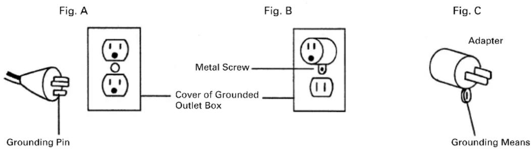
Grounded, cord -connected tools intended for use on a supply circuit having a nominal rating less than 150 volts: This tool is intended for use on a circuit that has an outlet that looks like the one illustrated in Fig. A. The tool has a grounding plug that looks like the plug illustrated in Fig. A. A temporary adapter, which looks like the adapter illustrated in Fig. B and C, may be used to connect this plug to a 2-pole receptacle as shown in Fig. B if a properly grounded outlet is not available. The temporary adapter should be used only until a properly grounded outlet can be installed by a qualified electrician. The green-colored rigid ear, lug, and the like, extending from the adapter must be connected to a permanent ground such as a properly grounded outlet box.
GROUNDING METHODS
SAVE THESE INSTRUCTIONS AND
MAKE THEM AVAILABLE TO OTHER USERS OF THIS TOOL!
NOTE: The information contained in this Instruction Manual is designed to assist you in the safe operation and maintenance of the power tool. Some illustrations in this Instruction Manual may show details or attachments that differ from those on your own power tool.
NAME OF PARTS

Fig. 1
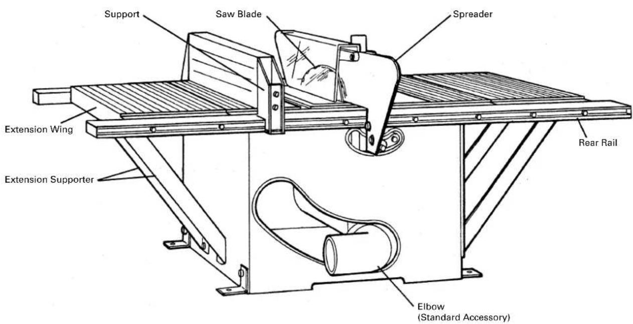
Fig. 2
SPECIFICATIONS
| Item Model C10RA2 | |
| Motor | Type Series commutator motor |
| Power source Single-phase AC 60Hz | |
| Voltage (volts) 115 | |
| Full-load current (Amp) 15 | |
| Applicable saw blade Outside Dia. 10" (255 mm) | |
| Hole Dia. 5/8" (15.9 mm) | |
| No load speed 5000 rpm | |
| Max. sawing dimension 90° Max. Height 3" | |
| Bevel 45° Max. Height 2 – 1/2" | |
| Net weight 64 lbs. (29 kg) | |
| Cord 3 conductor type cable 6.6 ft. (2 m) | |
ACCESSORIES
⚠ WARNING: Accessories for this power tool are mentioned in this Instruction Manual.
The use of any other attachment or accessory can be dangerous and could cause injury or mechanical damage.
STANDARD ACCESSORIES
| ① 10" (255 mm) TCT Saw Blade (1 piece) | ② Set Plate (4 pieces) | ③ Wrench (1 Piece) | ④ Hex. Wrench (1 Piece) | ⑤ Elbow (1 Piece) |
| For how to use, refer to page. 11 | For how to use, refer to page. 14 |
Fig. 3
OPTIONAL ACCESSORIES...sold separately
① Dado Insert (For dado cutter set) (Code No.314325) Convenient for dado cutting. Refer to parts list.
② Push Stick (Code No.314324) Convenient for ripping small pieces cutting. Refer to parts list.
③ Table Saw Stand (Code No.314819) Convenient for setting the table saw. Refer to Fig. 12-c.
⚠ WARNING: Using attachments or accessories not recommended in this manual can be dangerous and cause personal injury or mechanical damage to the saw.
APPLICATIONS
Wood (hard or soft woods)
UNPACKING
The parts illustrated in Fig. 4 described are packaged together with the tool. When unpacking, carefully confirm that all parts are accounted for.

Fig. 4
- Miter Gauge (1 piece) 8. Grip (1 piece)
- Saw Blade Guard and Spreader Assembly (1 piece)
- Elbow (1 piece) 10. 6 × 110 mm Bolt (1 piece)
- Rip Fence (1 piece) 11. 6 mm Spring Washer (2 pieces)
- Hex. Wrench (1 piece) 12. 6 mm Flat Washer (2 pieces)
- Wrench (1 piece)
-
Handle Bar (1 piece) 14. Set Plate (4 pieces)
-
6 × 90 mm Bolt (1 piece)
-
8 × 20 mm Bolt (with / washers) (4 pieces)
- Cusion (1 piece)
Make the following preparations before operating the power tool:
1. Installation
The table saw must be properly secured to a sturdy workbench, stand or cabinet.
Casters (if provided) on the workbench, stand or cabinet must be locked during operation.
If there is any tendency for the table saw to move during operation, this must be corrected immediately.

Fig. 5
(1) Place the table saw in the desired location.
Make certain that is (or will be) adequate space on all sides of the table saw for the workpiece.
To allow maximum flexibility for sheet material and long boards, 9 foot (2745 mm) clearance is recommended on all sides of the table saw.
(2) Secure the four set plates to the saw base at its four corners with four 8 × 20 mm bolts (with/washers) and four 8 mm nuts.
Square the table saw to the workbench, stand or cabinet. Make certain that all controls are easily reached and there is at least 6-11/16" (170 mm) behind the rear of the table to allow for the saw blade guard assembly.
Temporarily mark the location of the four base corners and set plate of the table saw.
(3) Remove the table saw, and locate a 11" (279 mm) or 12" (305 mm) square centered between the marks locating the body shell. Cut out and remove the square. This opening allows sawdust to fall out of the body shell.
⚠️ CAUTION: Failure to provide this opening can result in insufficient cooling air to the motor causing premature motor failure and a possible fire hazard.
(4) Replace the table saw, aligning it with the marks made above. Trace hole positions on the four set plates on the workbench, stand or cabinet with a pencil or the like.
(5) Remove the table saw, and drill a 5/16" (8 mm) hole in each location marked. Remove all sawdust or chips.
(6) Replace the table saw in the marked location. Check to see that the table saw does not lock on the workbench and all four set plates are in contact with the top of the workbench, stand or cabinet.
(7) Using suitable length four 2" (50 mm) bolts, nuts, and flat washers (not provided) secure the table saw to the workbench, cabinet or stand. Place a spring washer and flat washer on the bolt, place the bolt through the hole in the set plate and the top of the workbench stand, or cabinet. Add another flat washer and a nut. Do not tighten the nut yet. Repeat this operation for the other three locations. Tighten all nuts securely.
(8) Check the sturdiness of the resulting assembly.
ASSEMBLY PROCEDURES
⚠ WARNING: To avoid an accident or personal injury, always confirm that the switch is turned OFF and the power plug has been disconnected from the receptacle before assembly of this tool.
- Assembly of Handle Bar

Fig. 6
The handle bar allows faster turning of the wheel.
When properly assembled it with rotate freely but with only a small amount of play,
(1) Tighten the screw of the handle bar until it hits against the wheel.
(2) Securely tighten the handle bar nut with a wrench.
- Installing of Rip Fence
⚠️ CAUTION: The rip fence must be aligned parallel to the saw blade to minimize the kickback (refer to page 19).
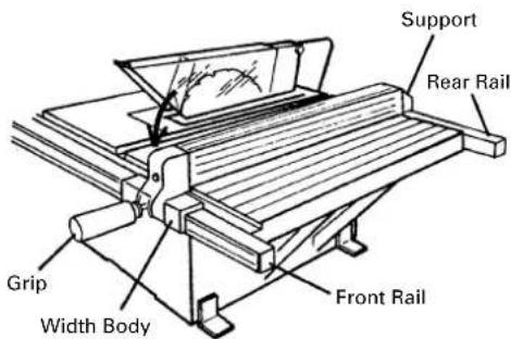
Fig. 7
The rip fence can be conveniently used to cut a workpiece into different pieces of precise width or into parallel pieces. It can be mounted on either the right or left side of the table.
(1) Tighten the screw of the grip.
(2) Catch the hook of the support in the bottom part of the rear rail.
(3) Lower the rip fence in the arrow direction, and fit the part of the width body and support to the groove of the front and rear rail.
(4) Confirm that the rip fence is moved right and left and it moves smoothly.
- Assembly of Miter Gauge

Fig. 8
The miter gauge is convenient for cutting long or angular pieces which are difficult to work on with the rip fence. It can be mounted on either the right or left side of the table. Align the sheet bar of miter gauge with the miter gauge groove and slide it in the direction indicated by the arrow through the front of the table.
4. Mounting and adjusting Saw Blade Guard Assembly

Fig. 9-b
⚠️ CAUTION: The saw blade guard and spreader assembly must be aligned properly to the saw blade in order to prevent kickback.
Mount the saw blade guard assembly, which includes the spreader and anti-kickback pawls (see Fig. 9-d).
(1) Mounting the spreader
①Loosen the saw blade tilt lock handle, move the saw blade tilting mechanism to the left and set the saw blade to 0^ by means of the stopper. Tighten the saw blade tilt lock handle to lock it in position.
②Turn the wheel fully clockwise and set the saw blade to the maximum cutting height (see Fig. 9-a).
③Put a 6 mm spring washer and a D13 flat washer on to the 6 × 90 mm and 6 × 110 mm bolts.
④Tentatively fasten the spreader on the rear section of the body using the cusion and two 6 mm bolts mentioned above (see Fig. 9-b and Fig. 9-d).
(The guard bracket must be attached to the spreader in advance.)

Fig. 9-c
(2) Adjusting the spreader
①Use a straightedge to align the spreader with the saw blade (see Fig. 9-c).
Tighten the two 6×16 mm bolts (see Fig. 9-d) with a wrench to lock the spreader.
②Check clearance between saw blade tip and spreader. It should be less than 1/2" (12.7 mm) at all positions. If not, loosen the two 6 × 16 mm bolts securing the spreader to the guard bracket with a wrench and move the spreader up and down. After adjustment of the spreader is complete, firmly retighten the two 6 × 16 mm bolts with a wrench (see Fig. 9-d).

Fig. 9-d
5. Mounting Table Insert

Fig. 10
The table insert is mounted to the table with two 5mm machine screws.
CAUTION: The table insert must be in place and securely fastened at all times.
6. Mounting Elbow (Chip Extraction Duct) (Standard Accessory)
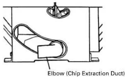
Fig. 11
Connect a 2 - 9/16" (65 mm) hose of dust collector to the chip extraction duct to suck cutting chips away. Mount the chip extraction duct on the chip discharge outlet at the body rear of the body.
7. Assembly of Table Saw Stand (Optional Accessory)

Fig. 12-a Fig. 12-b Fig. 12-c


natural_image
Simple line drawing of a chair frame with no text or symbolsAssemble it with the stay and leg(s). Set the stays below and assemble the legs outside (see Fig. 12-c).
Secure with cup square neck bolts and nuts (see Fig. 12-a).
Then attach rubber caps underneath the legs (see Fig. 12-b).
ADJUSTMENT
This tool is accurately adjusted before shipping from the factory.
Check the following accuracies and readjust them if necessary in order to obtain the best results in operation.
⚠ WARNING: To avoid an accident or personal injury, always confirm that the switch is turned off and the power plug has been disconnected from the receptacle before adjustment of this tool.
1. Adjustment of saw blade parallel to miter gauge groove.
This is the most probably difficult of the adjustments. Before shipment from the factory this adjustment was made but it should be rechecked and readjusted if necessary.
⚠️ CAUTION: This adjustment must be correct. Kickback could result and accurate cuts cannot be made.

Fig. 13-a
(1) Loosen the saw blade tilt lock handle by turning it counterclockwise. Move the saw blade tilting mechanism to the left and set the saw blade to 0^ with the stopper.
(2) Turn the wheel fully clockwise and set the saw blade to the maximum cutting height (see Fig. 13-a).
(3) Select a tooth on the saw blade which is bent to the right.
(4) Mark that tooth with a pencil or permanent marker.
(5) Set the miter gauge to 90^ and tighten the clamp handle (B) to lock it in that position. Place the miter gauge in the left hand miter gauge groove in the table top (see Fig. 13-b).
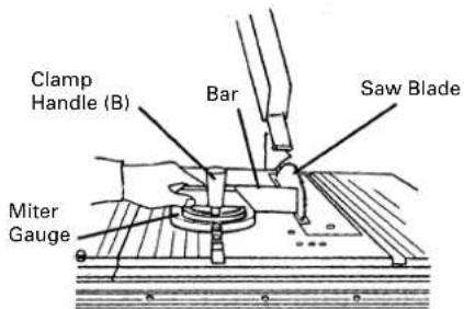
Fig. 13-b

Fig. 13-c
(6) Rotate the saw blade to bring the marked tooth in the front and about 1/2" (12.7 mm) above the table top.
(7) Place the bar of square flat against the miter gauge.
(8) Move the bar of square toward the saw blade until it just touches the tip of the marked saw blade tooth.
(9) Without disturbing the bar clamped to the miter gauge, move the miter gauge to the center of the saw blade.
(10)Slide the miter gauge rearward until the clamped bar is closest to the tip of the marked saw blade tooth (see Fig. 13-c).
(11) If the bar just touched the tooth when the gauge was in the front position, it should just touch the tooth in the rear position. Likewise, if there was some clearance between the bar and the tooth tip at the front, the same clearance should be at the rear.
(12) If the front and rear clearance are not identical,
①Remove the miter gauge.
②Loosen four 6mm flat screws.
③Move the body and adjust it so that a bar placed on the miter gauge is as wide as the clearance between the front and rear of the saw blade.
④Tighten the four 6mm flat screws.
2. Adjusting 90° and 45° positive stops

Fig. 14-a

Fig. 14-b
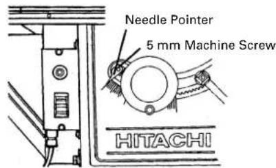
Fig. 14-c
This tool is equipped with positive stops for rapid and accurate positioning of the saw blade at 90° and left bevel 45° to the table. Check and adjust the positive stops by the following procedures.
(1) To adjust positive stop at 90^ .
①Turn the wheel fully clockwise and set the saw blade to the maximum cutting height.
②Loosen the saw blade tilt lock handle and move the saw blade tilting mechanism to the left until it hits against the stopper.
Then tighten the saw blade tilt lock handle (see Fig. 14-a).
③Use a square to check the saw blade is at a precise 90^ (see Fig. 14-b).
④ If the saw blade is not at a precise 90°, loosen the saw blade tilt lock handle by turning it counterclockwise. Loosen the 6mm machine screw (A) (see Fig. 13-c) a few turns and move the saw blade tilting mechanism until the blade is at 90° to the table (see Fig. 14-b).
⑤Tighten the saw blade tilt lock handle after adjustment.
⑥ Loosen the 5mm machine screw and set the needle pointer to 0°. On completion of adjustment, recheck the 90° of the saw blade and table (see Fig. 14-c).
(2) To adjust positive stop at left bevel 45°.
①Turn the wheel fully clockwise and set the saw blade to the maximum cutting height.
②Loosen the saw blade tilt lock handle and move the saw blade tilting mechanism to the right until it hits against the stopper.
Then tighten the saw blade tilt lock handle (see Fig. 15-a).
③ Use a 45^ gauge to check the saw blade is at a left bevel 45^ (see Fig. 15-b).

Fig. 15-b
3. Adjustment of rip fence

Fig. 16-a

Fig. 16-b
④ If the saw blade is not at a left bevel 45^ , loosen the saw blade tilt lock handle. Loosen the 6mm machine screw (B) (see Fig. 13-c) a few turns and move the saw blade tilting mechanism until the blade is at left bevel 45^ to the table (see Fig. 15-b).
⑤After adjustment, tighten the saw blade tilt lock handle.
⑥ On completion of adjustment, recheck the left 45^ bevel of the saw blade and table.
Before shipment from the factory the saw blade is set parallel to the miter gauge groove and the rip fence is adjusted parallel to the miter gauge groove. Check and adjust the parallel of the rip fence by the following procedures. In order to accurate work and prevent kickback when ripping. Before adjustment of rip fence, check and adjust slider (It is assembled under the width body.) to engage with the groove on front rail.
(1) Raise the grip to the upside and release the fixation of the rip fence (see Fig. 16-a).
(2) Position the rip fence at one edge of the miter gauge groove.
(3) Lower the grip to the bottom and fix the rip fence. The edge of the rip fence should line up parallel with the miter gauge groove.
(4) If the edge of the rip fence is not parallel with the miter gauge groove.
①Loosen the four 6 mm hex. hd. bolts securing the parallel bracket to the width body and support.
② Raise the grip to the upside and release the fixation of the rip fence.
Align the rip fence parallel to the miter gauge groove.
Lower the grip to the bottom and fix the rip fence.
③While holding the parallel bracket to prevent movement, tighten the four 6 mm hex. hd. bolts previously loosened (see Fig. 16-b).
④ Raise the grip to the upside and release the fixation of the rip fence. Move and return the parallel bracket adjacent to the miter gauge groove. Lower the grip to the bottom and fix the rip fence. And verify that the parallel bracket is parallel to the miter gauge groove.
⑤ Repeat adjustment until it is parallel.
⑥ After adjustment, tighten four 6 mm hex. hd. bolts.
⑦ On completion of adjustment, recheck the rip fence is parallel with the miter gauge groove.
4. Adjustment of pointer
The pointer is equipped to indicate the distance the rip fence is positioned away from the saw blade.
The pointer should indicate the accurate distance from the saw blade.
Check and adjust the pointer by the following procedures.
NOTE: The pointer will need to be readjusted whenever a different thickness saw blade is installed.

Fig. 17
To adjust pointer 0 setting.
(1) Raise the grip to the upside and release the fixation of the rip fence. And move the rip fence to bring it into tight contact with the side of the saw blade.
(2) Make sure that the pointer points to 0 on the scale provided on the table.
(3) If the pointer does not point to 0 on the scale,
①Lower the grip to the bottom and fix the rip fence.
②Loosen the 5 mm machine screw holding the pointer (see Fig. 17).
③Adjust the pointer to the 0 position and retighten the 5 mm machine screw.
④After adjustment, recheck to see that the pointer now points to 0.
5. Adjustment of Miter Gauge
The miter gauge should be squareness to the saw blade.
Check and adjust the miter gauge the following procedures.

Fig. 18
To adjust pointer 0 setting.
(1) Loosen the clamp handle (B) and place a square against both the saw blade and miter gauge. The pointer should indicate 90^ on the protractor scale on the miter gauge.
(2) If the pointer does not point to 0 on the miter gauge,
①Tighten clamp handle (B).
②Loosen the 5 mm machine screw on the sheet bar.
③ Adjust the pointer to the 90° position and tighten the 5 mm machine screw on the sheet bar (see Fig. 18).
④After adjustment, recheck to see that the pointer now points to 0.
BEFORE USING
- Make sure the switch is turned OFF.
⚠ WARNING: If the power cord is connected to the power source with the switch turned ON the power tool will start suddenly and can cause a serious accident.
- Make sure the power source is appropriate for the tool.
⚠ WARNING: Never connect the power tool unless the available AC power source is of the same voltage as that specified on the nameplate of the tool. Never connect this power tool to a DC power source.
- Check the saw blade for visible defects.
Confirm that the saw blade is free of cracks or other visible damage.
- Confirm that the saw blade is attached securely to the power tool.
Using the supplied wrench, tighten the set nut on the saw blade spindle to secure the saw blade.
For details, see Fig. 34 in the section on "SAW BLADE MOUNTING AND DISMOUNTING".
- Check the saw blade guard for proper operation.
Saw blade guard is designed to protect the operator from coming into contact with the saw blade during operation of the tool.
Always check that the saw blade guard moves smoothly.
⚠ WARNING: Never operate the power tool if the saw blade guard does not function smoothly.
- Check the Power Receptacle
To prevent overheating, accidental stopping or intermittent operation, confirm that the power cord plug fits properly in the electrical receptacle and does not fall out after it is inserted. Repair or replace the receptacle if it is faulty.
- Confirm the tool's power cord is not damaged
Repair or replace the power cord if an inspection indicates that it is damaged.
AFTER CONNECTING THE POWER PLUG TO AN APPROPRIATE AC POWER SOURCE, CHECK THE OPERATION OF THE TOOL AS FOLLOWS:
- Trial Run
After confirming that no one is standing behind, the power tool start and confirm that no operating abnormalities exist before attempting a cutting operation.
- Inspect the rotating stability of the saw blade
For precise cutting, rotate the saw blade and check for deflection to confirm that the blade is not noticeably unstable; otherwise vibrations might occur and cause an accident.
PRACTICAL APPLICATIONS
1. Switch operation

Fig. 19
To turn the table saw on, raise the red portion of the switch. To turn the table saw off, push the red portion of the switch. Try this operation without the saw being plugged in.
⚠ WARNING: Always remove the safety key from the switch when the table saw is not in use. This will ensure that the table saw cannot be turned on accidentally or by someone (especially a child) who is not qualified to use the table saw. If the safety key is left in the switch, serious personal injury can result.
- Overload protective device for motor
When the motor becomes overload, the overload protective device cuts off the current to stop the motor. In this case, push the reset button (after few minute later).
3. Raising and lowering saw blade
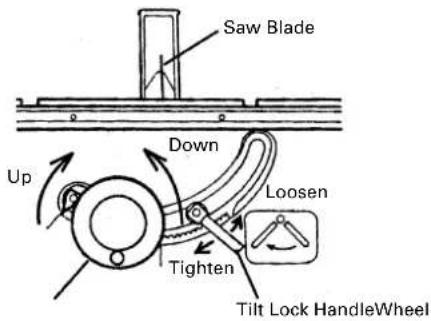
Fig. 20
(1) Raising saw blade.
Grasp the wheel and rotate it clockwise to raise the saw blade.
(2) Lowering saw blade.
Grasp the wheel and rotate it counterclockwise to lower the saw blade.
CAUTION: Adjust the saw blade height so it is about 1/8" (3.2 mm) above the top of the workpiece.
Raising the saw blade much higher than the workpiece does not make it cut better. It is unsafe and provides less table surface in front of the saw blade.
Never operate while saw blade rotating.
4. Saw Blade Tilting Operation
The saw blade tilt lock handle is spring loaded and can be repositioned by pulling out on the handle and repositioning it on the serrated stud located underneath the handle.
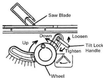
Fig. 21
WARNING: The saw tilt lock handle must be locked during all cutting operations.
Two methods are available tilting saw blade and are as follows.
(1) Rapid saw blade tilting.
Loosen saw blade tilt lock handle, move the wheel until the saw blade is at the desired angle and tighten saw blade tilt lock handle.
(2) Fine adjustment saw blade tilting.
①Loosen saw blade tilt lock handle.
②Push in wheel until teeth on hub of hand wheel engage with segment gear.
③Turn wheel to tilt the saw blade to the desired angle and tighten saw blade tilt lock handle.
5. Rip Fence Operation

Fig. 22
The rip fence can be used on either side of the saw blade. The pointer on rip fence indicates the distance between the saw blade and rip fence.
(1) Raise the grip to the upside and release the fixation of the rip fence.
(2) Move the rip fence right and left while pressing the width body against the table surface and set the desired distance from the saw blade.
(3) Lower the grip to the bottom and fix the rip fence.
⚠ WARNING:The grip must be locked during all cutting operations.
Confirm the rip fence has been properly locked before operation.
To prevent personal injury, never operate the power tool if the rip fence is loose.
CAUTION: Make sure that the rip fence is always in parallel with the miter gauge groove on the table.
6. Miter Gauge Operation

Fig. 23
The miter gauge can be used on either side of the miter gauge grooves on the table. However, for bevel cutting (the saw blade is tilted), use the miter gauge in the right side miter gauge groove to prevent hands or miter gauge from interfering with the saw blade guard. Miter gauge is accurately adjustable at 90° and 45° right and left in relation to the saw blade.
Intentional miter cut angle can be obtained easily.
(1) Loosen clamp handle (B).
(2) Turning the miter gauge to the desired angle.
(3) Tighten clamp handle (B) to lock the miter gauge.
For your own safety carefully read and observe the following warnings and precautions in addition to the [IMPORTANT INFORMATION], [SAFETY] and [WARNING]
- The saw blade is firmly locked.
- Never perform any operation "free hand" without using the miter gauge, rip fence, and or other auxiliary devices. To do so could cause accidents from kickback should the saw blade become locked in the workpiece material.
- When miter gauge is used, remove rip fence from table.
- When the miter gauge is used, securely tighten clamp handle (B).
- When rip fence is used, remove miter gauge from table.
- When the rip fence is used, securely lock the grip.
- If blade stalls or stops, TURN SWITCH OFF before releasing blade.
- Never remove small cut-off pieces with your fingers. Remove them by pushing them clear with a long stick.
- Never attempt to remove small cut-off pieces trapped inside the saw blade guard while the saw is running. Turn the switch "OFF", allow the saw blade to come to a complete stop, raise the saw blade guard, and remove the cut-offs.
- Adjust the saw blade height so it is about 1/8" (3.2 mm) above the top of the workpiece. More exposure would be hazardous (see Fig. 24).
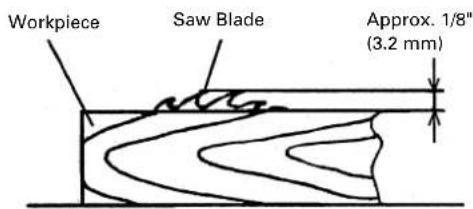
Fig. 24
-
Never touch any cut-offs while saw blade is running.
-
Feed material slowly in order to make fine cut, keep accuracy, and avoid overloading.
OPERATING INSTRUCTIONS
There are two basic types of cuts. Ripping and cross cutting. In general, cutting with the grain is ripping and across the gain is cross cutting. Neither ripping or cross cutting may be done safely freehand. Ripping requires the use of the rip fence and cross cutting uses the miter gauge. Safety glasses are being worn.
ALWAYS USE EYE PROTECTION WHEN WORKING WITH THE TOOL TO PREVENT EYE INJURY.
Ordinary eyeglasses do not provide adequate protection since the lenses are not made of safety glass. Also, use a face mask for additional safety and wear a dust mask if the cutting operation produces dust.
1. Ripping

Fig. 25
Confirm the following items before ripping.
(1) Rip fence is parallel to saw blade.
(2) Rip fence is securely fixed.
(3) Remove the miter gauge.
(4) Spreader is properly aligned with saw blade.
(5) Anti-kickback pawls are functioning properly (see Fig. 9-d).
Cutting operation
①Adjust the saw blade height so it is about 1/8" (3.2 mm) above the top of the workpiece.
②Hold the workpiece flat on the table and against the rip fence. Keep the workpiece about 1" (25 mm) away from the saw blade.

CAUTION: The workpiece must have a straightedge against the rip fence and must not be warped, twisted or bowed. Keep both hands away from the saw blade and away from the path of the saw blade.
③Turn on the switch on and allow the saw blade to come up to speed.
④ Keeping the workpiece against the table and rip fence, slowly feed the workpiece rearward all the way through the saw blade. Continue pushing the workpiece until it is clear of the guard and it falls off the rear of the table.
⑤ When ripping long boards or large panels, always use an adequate support.
A simple support can be prepared by fixing a piece of plywood to a sawhorse or the like.
⑥ When the width of rip is more than 6" (152 mm) feed the workpiece with one or both hands continuously until it is beyond the saw blade and anti-kickback pawls.

CAUTION: Do not push the free piece that is cut off, merely guide it.
⑦ When the width of rip 2" (50 mm) to 6" (152 mm) wide, use a push stick to feed the workpiece. (Push stick is optional accessory)
⑧When the width of rip is less than 2" (50 mm) wide, use an auxiliary guide a push block.
⑨ When ripping thin material (such as veneer), the workpiece may slide or bind between the bottom of rip fence and the table surface resulting in impossible ripping. Make a board which has the same height and length of the rip fence surface by using a piece of 3/4" (19 mm) thick plywood. Fix the board to the rip fence using four wood screws, so that the bottom of the board touches the table surface.

WARNING: Never operate to pull the workpiece back with the saw blade turning. Turn the switch off, allow the saw blade to complete stop, raise the anti-kickback pawls (see Fig. 9-d) on each side of the spreader if necessary and slide the workpiece out.
2. Bevel Ripping
This operation is the same as ripping except that the bevel angle is set to an angle other than 0^ .

WARNING: Only work with the workpiece and rip fence on the right side of the saw blade.
3. Ripping small pieces
⚠ WARNING: It is unsafe to rip small pieces. It is unsafe to put your hands close to the saw blade.

Fig. 26
When a small width is to be ripped and the hand cannot be safely put between the saw blade and rip fence, use one or more push sticks. Use them to hold the workpiece against the table and rip fence and push the workpiece fully past the saw blade.
4. Cross Cutting

Fig. 27
Confirm the following items before cross cutting.
(1) Remove the rip fence.
(2) Spreader is properly aligned with saw blade.
(3) Anti-kickback pawls are functioning properly (see Fig. 9-d).
Cutting Operation
①Adjust the saw blade height so it is about 1/8" (3.2 mm) above the top of the workpiece.
②Hold the workpiece firmly against the miter gauge with the path of the saw blade in line with the desired cut distance. Keep the workpiece about 1"(25 mm) away from the saw blade.
⚠️ CAUTION: Keep both hands away from the saw blade and away from the path of the saw blade.
③Turn the switch on and allow the saw blade to come up to speed.
④ While keeping the workpiece against the face of the miter gauge, and holding the workpiece flat against the table, slowly push the workpiece through the saw blade.
⚠️ CAUTION: Never operate to pull the workpiece back with the saw blade turning. Turn the switch off, allow the saw blade to complete stop, raise the anti-kickback pawls on each side of the spreader if necessary and slide the workpiece out.
5. Bevel Ripping
Cross Cutting
This operation is the same as cross cutting except that the bevel angle is set to an angle other than 0^ .
⚠ WARNING: Only operate with the workpiece and miter gauge on the right side of the table.
6. Mitering

Fig. 28
This operation is the same as cross cutting expect that the miter gauge is locked at an angle other than 90^ .
⚠ WARNING: Hold the workpiece firmly against the miter gauge and feed the workpiece slowly into the saw blade to prevent the workpiece from moving.
7. Compound Mitering
This is compound of bevel cross cutting and mitering. It is infrequently used. Follow the instruction for both bevel cross cutting and mitering.
8. Work Helpers
For certain operations, work helpers such as a push stick, push block, auxiliary fence, work support or the like should be used.
These helpers can be made by yourself using this table saw.
Refer to following figures which shows typical work helpers dimensions.

Fig. 29
(1) Push Stick
When the width of rip 2" (50 mm) to 6" (152 mm) wide, use a push stick to feed the workpiece.
A push stick is available as an optional accessory (refer to page 10). A push stick can be easily made from a piece of 3/4" (19 mm) thick plywood.

Fig. 30
(2) Push Block
When the width of rip is less than 2" (50 mm) wide, use a push block.
① Use a piece of 3/8" (9.5 mm) and 3/4" (19 mm) thick plywood.
② Glue the small piece of wood 3/8" (9.5 mm) × 3/8" (19 mm) × 2-1/2" (63.5 mm).
③Provide a grip in the center of the plywood and fix together with glue and wood screws.
④ A and B edges must be parallel.
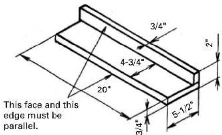
Fig. 31
(3) Auxiliary Fence
When the width of rip is less than 2" (50 mm) the push stick cannot be used because the saw blade guard (see Fig. 23) will interfere with a push stick, use an auxiliary fence and push stick.
① Use a piece of 3/8" (9.5 mm) and 3/4" (19 mm) thick plywood.
②Fasten both together with glue and wood screws.
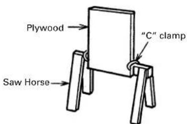
Fig. 32
CAUTION: The push block is used with the auxiliary fence. The 4-3/4" (121 mm) dimension must be the same on both.
(4) Work Support
① Clamp a piece of plywood to a sawhorse with "C" clamps.
②Adjust the height of the plywood to level it with the height of the table surface.
9. Dado Cutting
⚠ WARNING: To prevent an accident or personal injury, always turn off the switch and disconnect the power plug from the receptacle before mounting or dismounting the dado blade set.
Never attempt to stack dado blades thicker than 1/2" (12.7 mm) thick. Never use the dado set for cut-offs. Never attempt bevel cuts when dadoing. Never use dado if there is vibration (flutter) or a strange noise. Never attempt dado in other than wood. Never put hands over the dado blade.
Take every precaution to prevent kickback of the workpiece. Feed workpiece slowly, especially when cutting deep or wide grooves. When the dado head is hidden from view while cutting, your hands should never be on top of the workpiece. When using a dado blade, the saw blade guard assembly must be removed since there is not cut completely through the wood which will allow the spreader to pass through the workpiece.
⚠️ CAUTION: Use extreme caution when dado cutting.
Always stop the tool and wait for dado blade to come to a complete stop. Then simply withdraw the wood. Use a push stick. Use rip fence or miter gauge. Be alert for potential kickback conditions. Follow the dado blade set manufactures recommendations. When using a dado blade set, the depth of cut is not indicated by the pointer. To know the depth cut, you must measure it with a ruler. Be sure to place the saw blade guard assembly back in its original position and check adjustments when the dado cuts are completed.
A groove cut into the workpiece is called dado. This dado does not extend completely through the workpiece. The dado can be made in various widths and depths according to the need. A typical use for a dado is to make the groove for a shelf. A saw blade can be used to make a dado of any width by marking multiple cuts side by side. However, it is much easier to use a dado blade. The first has to small blades and a series of chips to the remove scrap between the blades. The second type consists of a small thick blade which is caused to wobble by its mounting hubs. This saw will accept dado blades of the cutter chip type to 6" (152 mm) in diameter and 1/2" (12.7 mm) in which. Most wobble type blades are too wide fit on the saw blade spindle safely. A dado blade requires a table insert which has wider opening. This dado insert is available as an optional accessory (refer to page 10). Purchase the dado blade set separately.
Mounting the dado blade set
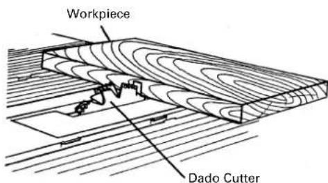
Fig. 33
Mounting the dado blade set (see Fig. 33), procedures as follows:
①Remove the saw blade guard assembly with the spreader.
②Remove the table insert.
③Dismount the saw blade.
④Mount the dado blade with the teeth pointing down at the front of the table (Using the instructions with the dado blade set).
⑤Mount the dado table insert (optional accessory), instead of the table insert.
⚠️ CAUTION: While tightening the set nut (see Fig. 34), be careful to maintain the even spacing between the tips of the inside cutters. Rotate the dado blade one turn by hand to make sure that it does not contact anything before operation.
SAW BLADE MOUNTING AND DISMOUNTING
⚠ WARNING: To prevent an accident or personal injury, always turn off the switch and disconnect the power plug from the receptacle before mounting or dismounting a saw blade.
1. Mounting the saw blade

Fig. 34
(1) Turn the wheel (see Fig. 1) fully clockwise and set the saw blade to the maximum cutting height (see Fig. 14-a).
(2) Tighten the saw blade tilt lock handle and lock the saw blade at 90^ .
(3) Remove the table insert on the table.
(4) Mount the washer (A), saw blade and washer (A) in this order on the saw blade spindle. (The saw blade with the teeth pointing down at the front of the table.)
(5) Using the open end wrench and place the wrench on the flats on the saw blade spindle. Hold the saw blade spindle from turning and tighten nut using the remaining hex. wrench by turning the set nut clockwise.
(6) Replace the table insert on the table.
⚠ WARNING: Be sure to grip set nut carefully with the hex. wrench. A serious injury can be sustained, if your grip should slip, the hex. wrench come off the nut, and your hand strike the sharp blade edges.
When mounting the saw blade, confirm that the rotation indicator mark on the sawblade and the rotation direction of the saw are properly matched.
Tighten the set nut so it does not come loose during operation. Confirm the set nut (see Fig. 34) has been properly tightened before the power tool is started.
2. Dismounting the saw blade
Dismount the saw blade by reversing the mounting procedures described in paragraph 1 above.
MAINTENANCE AND INSPECTION
⚠ WARNING: To avoid an accident or personal injury, always confirm that the switch is turned OFF and that the power plug has been disconnected from the receptacle before performing any maintenance or inspection of this tool.
1. Inspecting the saw blade
Always replace the saw blade immediately upon the first sign of deterioration or damage. A damaged saw blade can cause personal injury and a worn saw blade can cause ineffective operation and possible overload to the motor.
⚠️ CAUTION: Never use a dull saw blade. When a saw blade is dull, its resistance to the hand pressure applied by the tool handle tends to increase, making it unsafe to operate the power tool.
2. Inspecting the carbon brushes (Fig. 35 and Fig. 36)
The carbon brushes in the motor are expendable parts. If the carbon brushes become excessively worn, motor trouble might occur. Therefore, inspect the carbon brushes periodically and replace them. Check the carbon brushes after the first 50 hours of use for a new machine or after a new set of carbon brush have been installed. After the first check, examine them after each about 10 hours of use until such time that replacement is necessary.
When the carbon on either brush is worn to 3/16" (5 mm) in length or if either spring or shunt wire is burned or damaged in any way, replace both carbon brushes (see Fig. 35). If the carbon brushes are found serviceable after removing, reinstall them in the same position as before removed. Also, keep the carbon brushes clean so that they will slide smoothly within the brush holders. The carbon brushes can easily be removed after removal of the brush caps (see Fig. 36) with a slotted (minus) screwdriver.
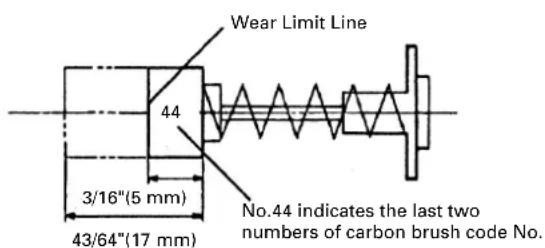
Fig. 35

Fig. 36
3. Inspecting the mounting screws
Regularly inspect each component of the power tool for looseness.
Re-tighten mounting screws on any loose part.
⚠ WARNING: To prevent personal injury, never operate the power tool if any components are loose.
4. Inspecting the saw blade guard for proper operation.
Before each use of the tool, test the saw blade guard (see Fig. 1) to assure that they are in good condition and that they move smoothly. Never use the tool unless the saw blade guard operates properly and unless they are in good mechanical condition. Ensure the anti-kickback pawls are always sharp so they dig into the workpiece to help prevent kickbacks. If any damage has occurred, repair it promptly.
5. Frequently clean the saw blade guard.
Wipe off saw dust attached to the inside of the see-through saw blade guard using a soft cloth. Do not use solvent (gasoline, thinner etc.), solvents will damage plastic parts.
6. Storage
Confirm that the switch is turned OFF, that the power plug has been removed from the receptacle and that the safety key has been removed and has been in a secure place, after operation of the tool has been completed. When the tool is not in use, keep it stored in a dry place out of the reach of children.
7. Lubrication
Lubricate the following moving parts and rotating parts once a month to keep the power tool in good operating condition for a long time (see Fig. 1 and Fig. 2). Use of machine oil is recommended.
Oil supply points:
Rotary and moving portion of wheel
8. Cleaning
Periodically remove chips and other waste material from the surface of the power tool with a damp, soapy cloth. To avoid a malfunction of the motor, protect it from contact with oil or water.
SERVICE AND REPAIRS
All quality power tools will eventually require servicing or replacement of parts because of wear from normal use. To assure that only authorized replacement parts will be used, all service (other than routine maintenance) must be performed by an AUTHORIZED HITACHI POWER TOOL REPAIR CENTER ONLY.
NOTE: Specifications are subject to change without any obligation on the part of HITACHI.
INFORMATIONS IMPORTANTES
CHOSES A NE PAS FAIRE
POUR GARANTIR UNE UTILISATION EN TOUTE SÉCURITÉ, NE JAMAIS VIOLER LES CONSIGNES SUIVANTES:
Fig. 4
natural_image
Technical line drawing of a mechanical assembly with a foot and mounting bracket (no text or symbols)natural_image
Simple line drawing of a chair frame with no text or symbolsFig. 29
(1) Poussoir-martyr
Fig. 30
(2) Bloc de poussée
Points de lubrification:
Fig. 4
natural_image
Simple line drawing of a ladder structure with no text or symbolsFig. 29
(1) Varilla de empuje
Fig. 30
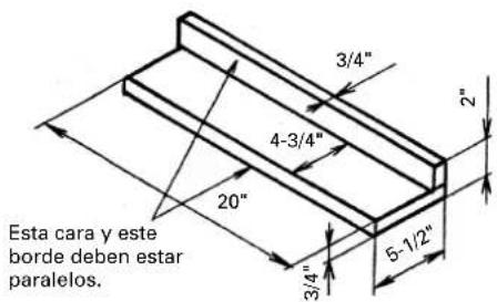
Fig. 31

Fig. 32
(2) Taco de empuje
Model C10RA2

Table Saw Parts List
| ITEM NO. | PART NAME | ITEM NO. | PART NAME |
| 1 | BLADE GUARD ASS'Y (INCLUD.2-25) | 67 | TABLE |
| 2 | NUT CHUCK M6 | 68 | RAIL |
| 3 | BLADE GUARD | 69 | SIDE COVER (RIGHT) |
| 4 | SELF-LOCKING RING | 70 | SCALE (RIGHT) |
| 5 | BOLT M6 × 40 | 71 | EXTENSION WING (RIGHT) |
| 6 | ARM | 72 | SIDE COVER (LEFT) |
| 7 | RIVET | 73 | HEX. SOCKET HD. CAP BOLT M6 × 35 |
| 8 | BOLT M6 × 110 | 74 | BEVEL GEAR (A) |
| 9 | SPRING WASHER M6 | 75 | SLIDE PLATE |
| 10 | BOLT WASHER M6 | 76 | SLIDE BRACKET |
| 11 | BOLT M6 × 90 | 77 | SPRING WASHER M6 |
| 12 | GUARD BRACKET | 78 | BOLT M6 × 35 |
| 13 | NUT M6 | 79 | MITER GAUGE ASS'Y (INCLUD. 80-86) |
| 14 | CUSHION | 80 | CLAMP HANDLE (B) |
| 15 | BUSHING | 81 | FLAT WASHER M6.4 |
| 16 | BOLT M6 × 16 | 82 | MITER GAUGE |
| 17 | SPRING WASHER M6 | 83 | MACHINE SCREW M5 × 6 |
| 18 | WASHER | 84 | ANGLE POINTER |
| 19 | SELF-LOCKING RING | 85 | PIN |
| 20 | KICK BACK PAWL | 86 | SHEET BAR |
| 21 | BUSHING | 87 | HEX. SOCKET SET SCREW M6 × 6 |
| 22 | ROLL PIN D4 × 22 | 88 | FLAT WASHER M8 × 14.3 |
| 23 | SPRING | 89 | BEVEL GEAR (B) |
| 24 | SPREADER | 90 | SCREW BAR |
| 25 | ROLL PIN | 91 | NUT CHUCK M8 |
| 26 | RIP FENCE ASS'Y (INCLUD.27-36, 39-47, 49-57, 161-163) | 92 | BODY |
| 27 | TAPPING SCREW D5 × 25 | 93 | FLAT WASHER M6.4 × 12.7 |
| 28 | COMPRESSION SPRING 12L | 94 | SPECIAL NUT CHUCK M6 |
| 29 | REAR CLAMP | 95 | GUARD |
| 30 | SPRING PIN | 96 | SPRING WASHER M6 |
| 31 | SLIDER (REAR) | 97 | MACHINE SCREW M6 × 12 |
| 32 | HEX. NUT M4 | 98 | WASHER(A) |
| 33 | PAN HD. SCREW M5 × 25 | 99 | SET NUT |
| 34 | COUNTER HD. SCREW M4 × 20 | 100 | TAPPING SCREW D5 × 10 |
| 35 | SUPPORT | 101 | BLADE GUARD |
| 36 | COMPRESSION SPRING 45L | 102 | FLAT WASHER M8 × 15 |
| 39 | CONNECTING BAR | 103 | PIVOT SUPPORT |
| 40 | HEX. SOCKET HD. BOLT M6 × 16 | 104 | SPRING WASHER M6 |
| 41 | FLAT WASHER 1/4" × 5/8" | 105 | NUT M6 |
| 42 | PARALLEL BRACKET | 106 | HEX. SOCKET SET SCREW M6 × 6 |
| 43 | ROUND WASHER HD. SCREW M5 × 8 | 107 | ANCHOR BLOCK |
| 44 | NEEDLE POINTER | 108 | FLAT WASHER M9.5 |
| 45 | COUNTER HD. SCREW M4 × 12 | 109 | BOLT (W/WASHERS) M8 × 16 (BLACK) |
| 46 | WIDTH BODY | 110 | SPECIAL BOLT M6 × 35 |
| 47 | SCREW M5 × 10 | 111 | SPRING WASHER M6 |
| 49 | SPRING PIN | 112 | MACHINE SCREW M6 × 12 |
| 50 | SLIDER (FRONT) | 113 | BRACKET |
| 51 | HEX. NUT M4 | 114 | SPACER |
| 52 | FRONT CLAMPER | 115 | NUT M6 |
| 53 | RUBBER PIN | 116 | COMPRESSION SPRING 20L |
| 54 | ECCENTRIC SHAFT | 117 | FLAT WASHER M16 |
| 55 | NUT M8 | 118 | COMPRESSION SPRING 57L |
| 56 | CLAMP BOLT | 119 | REGULATING BOLT |
| 57 | GRIP | 120 | ROLL PIN D3 × 18 |
| 58 | TABLE INSERT FOR SAW BLADE | 121 | WASHER |
| 59 | MACHINE SCREW M5 × 8 | 122 | BOLT (W/WASHERS) M6 × 12(BLACK) |
| 60 | FLAT HD. SCREW M6 × 25 | 123 | BODY SHELL |
| 61 | SEAL LOCK SCREW M6 × 20 | 124 | WARNING LABEL(B) |
| 62 | MACHINE SCREW (W/WASHERS) M6 × 20 | 125 | WARNING LABEL(A) |
| 63 | EXTENSION WING (LEFT) | 126 | NAME PLATE |
| 64 | SCALE (LEFT) | 127 | SEGMENT GEAR |
| 65 | SCALE (CENTER) | 128 | HITACHI LABEL |
| 66 | SEAL LOCK SCREW M6 × 10 | 129 | FLAT WASHER M6 × 25 |
Table Saw Parts List
| ITEM NO. | PART NAME | ITEM NO. | PART NAME |
| 130 | TENSION HANDLE | 148 | STRAIN RELIEF (RU-1435) |
| 131 | WHEEL | 149 | BOLT WASHER M4 |
| 132 | HANDLE | 150 | TAPPING SCREW D4 × 10 |
| 133 | FLAT WASHER M9.5 | 151 | POWER CABLE |
| 134 | LABEL | 152 | CIRCUIT BREAKER SWITCH |
| 135 | PAN HD. TAPPING SCREW D4 × 12 | 153 | BOLT (W/WASHERS) M8 × 20 (BLACK) |
| 136 | POINTER BRACKET | 154 | EXTENSION SUPPORTER (R) |
| 137 | BOLT WASHER M8 | 155 | TAPPING SCREW D5 × 16 |
| 138 | NUT M8 | 156 | PAN HD. TAPPING SCREW D4 × 8 |
| 139 | NEEDLE POINTER | 157 | TOOTHED LOCK WASHER M4 |
| 140 | TOOTHED LOCK WASHER M5 | 158 | SWITCH PLATE |
| 141 | MACHINE SCREW M5 × 8 | 159 | POCKER SWITCH |
| 142 | EXTENSION SUPPORTER (L) | 160 | INTERNAL WIRE |
| 143 | SPONGE | 161 | RUBBER WHEEL |
| 144 | STRAIN RELIEF (RA-1418) | 162 | SPRING PIN D4.3 × 20 |
| 145 | BOLT (W/WASHERS) M8 × 20 (BLACK) | 163 | SPRING PIN D3.3 × 19 |
| 146 | SET PLATE | ||
| 147 | SWITCH BOX |
Motor Parts List
| ITEM NO. | PART NAME | ITEM NO. | PART NAME |
| 201 | SPINDLE ASS'Y (INCLUD. 202, 206-210) | 215 | BAFFLE |
| 202 | PARALLEL KEY | 216 | TAPPING SCREW D5 × 60 |
| 203 | MACHINE SCREW M4 × 12 | 217 | TOOTHED LOCK WASHER M5 |
| 204 | SPRING WASHER M4 | 218 | STATOR 115V |
| 205 | BEARING RETAINER | 219 | BEARING BUSHING |
| 206 | BALL BEARING 6204VVCMPS2L | 220 | BRUSH CAP |
| 207 | COLLAR FOR D17 | 221 | CARBON BRUSH (1 PAIR) |
| 208 | HELIX GEAR | 222 | HOUSING ASS'Y (INCLUD. 223, 226) |
| 209 | RETAINING RING FOR D17 SHAFT | 223 | BRUSH HOLDER |
| 210 | NEEDLE BEARING | 224 | SPRING WASHER M5 |
| 211 | BRACKET | 225 | MACHINE SCREW M5 × 30 |
| 212 | ARMATURE ASS'Y 115V (INCLUD. 213, 214, 219) | 226 | HEX. SOCKET SET SCREW M5 × 8 |
| 213 | BALL BEARING 6201VVCMPS2L | 227 | STRAIN RELIEF (RU-1435) |
| 214 | BALL BEARING 6200VVCMPS2L | 228 | MOTOR NAME PLATE |
Standard Accessories
| ITEM NO. | PART NAME | ITEM NO. | PART NAME |
| 701 | WRENCH 22MM | ||
| 702 | WRENCH 23/26MM | ||
| 703 | ELBOW | ||
| 704 | TCT SAW BLADE 255MM-D15.88 HOLE-NT36 | ||
| 705 | STAND |
Optional Accessories
| ITEM NO. | PART MANE | ITEM NO. | PART NAME |
| 901 | TABLE INSERT FOR CUTTER | ||
| 902 | PUSH STICK | ||
Issued by
Hitachi Koki Co., Ltd.
Sinagawa Intercity Tower A,
15-1, Konan 2-chome, Minato-ku, Tokyo 108-6020, Japan
Distributed by
Hitachi Koki U.S.A., Ltd.
3950 Steve Reynolds Blvd.
Norcross, GA 30093
Hitachi Koki Canada Co.
6395 Kestrel Road
Mississauga ON L5T 1Z5
- INSTRUCTION MANUAL AND SAFETY INSTRUCTIONS
- WARNING
- MODE D'EMPLOI ET INSTRUCTIONS DE SECURITE
- ⚠ AVERTISSEMENT
- SAFETY
- TABLE DES MATIERES
- Français
- SÉCURITÉ
- UTILISATION ET ENTRETIEN
- MEANINGS OF SIGNAL WORDS
- IMPORTANT SAFETY INSTRUCTIONS FOR USING ALL POWER TOOLS
- Specific Safety Rules for Use of this Power Tool
- DO's
- ALWAYS OBSERVE THE FOLLOWING RULES TO ASSURE SAFE USE OF THIS TOOL:
- DON'Ts
- NEVER VIOLATE THE FOLLOWING RULES TO ASSURE SAFE USE OF THIS TOOL:
- FOR YOUR OWN SAFETY READ THIS INSTRUCTION MANUAL BEFORE OPERATING THE TABLE SAW
- REPLACEMENT PARTS
- USE PROPER EXTENSION CORD
- GROUNDING INSTRUCTIONS
- SAVE THESE INSTRUCTIONS AND
- MAKE THEM AVAILABLE TO OTHER USERS OF THIS TOOL!
- NAME OF PARTS
- SPECIFICATIONS
- ACCESSORIES
- STANDARD ACCESSORIES
- OPTIONAL ACCESSORIES...sold separately
- APPLICATIONS
- UNPACKING
- Installation
- ⚠️ CAUTION: Failure to provide this opening can result in insufficient cooling air to the motor causing premature motor failure and a possible fire hazard.
- ASSEMBLY PROCEDURES
- Mounting and adjusting Saw Blade Guard Assembly
- ⚠️ CAUTION: The saw blade guard and spreader assembly must be aligned properly to the saw blade in order to prevent kickback.
- Mounting Table Insert
- CAUTION: The table insert must be in place and securely fastened at all times.
- Mounting Elbow (Chip Extraction Duct) (Standard Accessory)
- Assembly of Table Saw Stand (Optional Accessory)
- ADJUSTMENT
- Adjustment of saw blade parallel to miter gauge groove.
- Adjusting 90° and 45° positive stops
- Adjustment of rip fence
- Adjustment of pointer
- NOTE: The pointer will need to be readjusted whenever a different thickness saw blade is installed.
- Adjustment of Miter Gauge
- BEFORE USING
- PRACTICAL APPLICATIONS
- Switch operation
- Raising and lowering saw blade
- CAUTION: Adjust the saw blade height so it is about 1/8" (3.2 mm) above the top of the workpiece.
- Saw Blade Tilting Operation
- WARNING: The saw tilt lock handle must be locked during all cutting operations.
- Rip Fence Operation
- ⚠ WARNING:The grip must be locked during all cutting operations.
- CAUTION: Make sure that the rip fence is always in parallel with the miter gauge groove on the table.
- Miter Gauge Operation
- OPERATING INSTRUCTIONS
- ALWAYS USE EYE PROTECTION WHEN WORKING WITH THE TOOL TO PREVENT EYE INJURY.
- Ripping
- Bevel Ripping
- Ripping small pieces
- ⚠ WARNING: It is unsafe to rip small pieces. It is unsafe to put your hands close to the saw blade.
- Cross Cutting
- ⚠️ CAUTION: Keep both hands away from the saw blade and away from the path of the saw blade.
- ⚠️ CAUTION: Never operate to pull the workpiece back with the saw blade turning. Turn the switch off, allow the saw blade to complete stop, raise the anti-kickback pawls on each side of the spreader if necessary and slide the workpiece out.
- Bevel Ripping
- ⚠ WARNING: Only operate with the workpiece and miter gauge on the right side of the table.
- Mitering
- ⚠ WARNING: Hold the workpiece firmly against the miter gauge and feed the workpiece slowly into the saw blade to prevent the workpiece from moving.
- Compound Mitering
- Work Helpers
- Push Stick
- Push Block
- Auxiliary Fence
- CAUTION: The push block is used with the auxiliary fence. The 4-3/4" (121 mm) dimension must be the same on both.
- Work Support
- Dado Cutting
- ⚠ WARNING: To prevent an accident or personal injury, always turn off the switch and disconnect the power plug from the receptacle before mounting or dismounting the dado blade set.
- ⚠️ CAUTION: Use extreme caution when dado cutting.
- Mounting the dado blade set
- SAW BLADE MOUNTING AND DISMOUNTING
- Mounting the saw blade
- Dismounting the saw blade
- MAINTENANCE AND INSPECTION
- Inspecting the saw blade
- Inspecting the carbon brushes (Fig. 35 and Fig. 36)
- Inspecting the mounting screws
- ⚠ WARNING: To prevent personal injury, never operate the power tool if any components are loose.
- Inspecting the saw blade guard for proper operation.
- Frequently clean the saw blade guard.
- Storage
- Lubrication
- Cleaning
- SERVICE AND REPAIRS
- INFORMATIONS IMPORTANTES
- CHOSES A NE PAS FAIRE
- POUR GARANTIR UNE UTILISATION EN TOUTE SÉCURITÉ, NE JAMAIS VIOLER LES CONSIGNES SUIVANTES:
- Poussoir-martyr
- Bloc de poussée
- Varilla de empuje
- Taco de empuje
- Hitachi Koki Co., Ltd.
- Hitachi Koki U.S.A., Ltd.
- Hitachi Koki Canada Co.
Brand : HITACHI
Model : C 10RA2
Category : Saw