NPPAC12HKM - Air-conditioner Norpole - Free user manual and instructions
Find the device manual for free NPPAC12HKM Norpole in PDF.


| Product Type | Portable Air Conditioner |
| Brand | Norpole |
| Model | NPPAC12HKM |
| Cooling Capacity | 12000 BTU/h |
| EER (Energy Efficiency Ratio) | 12.0 |
| Dehumidification Capacity | 50 pints/day |
| Fan Speeds | 3 (High, Medium, Low) |
| Timer | 24-hour programmable timer |
| Remote Control | Yes |
| Dimensions (W x D x H) | 18.5 x 16.9 x 28.7 inches |
| Weight | 75 lbs |
| Power Supply | 115V / 60Hz |
| Power Consumption | 1100W (cooling) |
| Refrigerant Type | R410A |
| Noise Level | 56 dB (low speed) |
| Air Flow | 400 CFM |
| Filter Type | Washable mesh filter |
| Maintenance | Clean filter every 2 weeks; wipe exterior with soft cloth |
| Safety Features | Auto power-off, tip-over switch |
| Warranty | 1 year limited warranty |
| Spare Parts Available | Remote control, filter, exhaust hose kit |
Frequently Asked Questions - NPPAC12HKM Norpole
User questions about NPPAC12HKM Norpole
0 question about this device. Answer the ones you know or ask your own.
Ask a new question about this device
Download the instructions for your Air-conditioner in PDF format for free! Find your manual NPPAC12HKM - Norpole and take your electronic device back in hand. On this page are published all the documents necessary for the use of your device. NPPAC12HKM by Norpole.
USER MANUAL NPPAC12HKM Norpole
natural_image
Line drawing of a rectangular electronic device with a recessed top and mounting base (no text or symbols)Model NPPAC12HKM
READ THIS MANUAL CAREFULLY BEFORE USING YOUR PORTABLE AIR CONDITIONER AND KEEP IT FOR FUTURE REFERENCE.
norpole
PRODUCT REGISTRATION
Thank you for purchasing a Norpole™ product. The first step to protect your new product is to complete the product registration on our website: www.mcappliance.com/register. The benefits of registering your product include the following:
- Registering your product will allow us to contact you regarding a safety notification or product update.
- Registering your product will allow for more efficient warranty service processing when warranty service is required.
- Registering your product could act as your proof of purchase in the event of insurance loss.
Once again, thank you for purchasing a Norpole product.
CONTENTS
PRODUCT REGISTRATION.... 2
IMPORTANT SAFETY INSTRUCTIONS 4
SPECIFICATIONS....6
PARTS IDENTIFICATION 7
INSTALLATION INSTRUCTIONS 8
REMOTE CONTROL 13
OPERATION INSTRUCTIONS 15
CARE AND MAINTENANCE.... 19
TROUBLESHOOTING 20
LIMITED WARRANTY.... 21
IMPORTANT SAFETY INSTRUCTIONS
EXPLANATION OF SYMBOLS
▲ WARNING: Hazards or unsafe practices which COULD result in severe personal injury or death.
CAUTION: Hazards or unsafe practices which COULD result in minor personal injury or property damage.
IMPORTANT SAFETY INSTRUCTIONS
- Read all instructions before using the appliance.
- ▲ WARNING: To prevent injuries or property damage, the following instructions must be followed.
- This appliance should not be operated, cleaned or maintained by anyone that is not able to follow proper safety procedures or does not have experience with this type of equipment, unless under close supervision.
- ▲ WARNING: DO NOT use in an area where it may be exposed to combustible gases or liquids, as this may cause a fire.
- ▲ CAUTION: Installation must be performed according to the installation instructions and ALWAYS use the correct tools as specified. Use only accessories and parts included with the appliance. Improper installation can cause water leakage, electrical shock, or fire.
- Place the unit on a level, sturdy section of the floor, away from heat sources or anywhere it could get wet.
- DO NOT operate in a wet environment, such as a bathroom or laundry room.
- DO NOT stand, sit, or place anything on top of the unit.
- DO NOT let children operate or play on or around the air conditioner. Children should be supervised around the unit at all times.
- ▲ CAUTION: The power cord is equipped with a 3-prong grounding plug to protect against shock hazards. ALWAYS plug cord into a properly installed and grounded 3-prong wall receptacle. Refer to the manufactures rating label for electrical and other technical data specific to this unit.
- DO NOT modify or cut the power cord, or use any other cord or plug. If the cord or plug is damaged, DO NOT use. Contact customer service or a qualified service technician for replacement or repair.
- DO NOT run cord under carpeting, throw rugs, runners, or similar coverings. DO NOT route cord under furniture, appliances, or any heavy object. Place the cord where it will not be tripped over.
- DO NOT start or stop the unit by turning the power on or off.
- DO NOT insert or pull out the plug with wet hands.
- DO NOT use this item on a solid state speed control device (such as a fan control wall switch).
- DO NOT obstruct the unit to ensure proper function and safety.
- DO NOT insert your finger or other foreign objects into grills or openings.
- ▲ CAUTION: ALWAYS turn off and unplug the unit prior to cleaning or maintenance.
- Contact customer service or an authorized service technician for repair or maintenance of this unit. DO NOT try to take apart or repair the unit by yourself.
-
Turn off and unplug the unit if strange sounds, smells, or smoke come from it.
-
If the appliance is knocked over during use, turn off the unit and unplug it immediately. Visually inspect the unit to ensure there is no damage. If there is any damage, or you suspect the unit has been damaged, contact a technician or customer service for assistance.
- If water spills into the unit, turn it off, unplug it, and contact a qualified service technician.
- DO NOT try to move the unit when the tank is full, or force the castors to roll on carpet. Doing so may cause the unit to tip over and spill water.
- ALWAYS insert the filters securely. Clean filter once every two weeks.
READ AND FOLLOW THIS SAFETY INFORMATION CAREFULLY SAVE THESE INSTRUCTIONS
SPECIFICATIONS
Figure 1
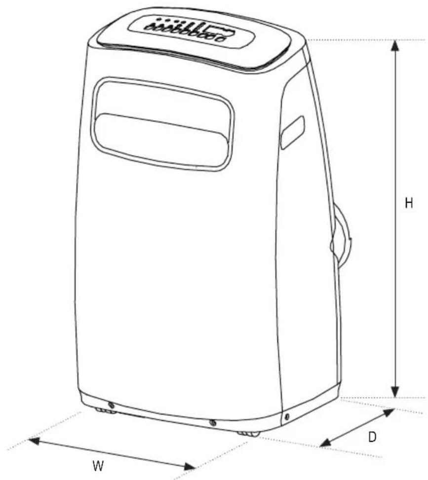
| Dimensions(W x H x D) | 18.0" x 14.4" x 30.5"18.0" x 14.4" x 30.5" |
| Weight | 70.3 lbs. |
| BTU | Cooling - 12000Heating - 10000 |
| Voltage 115V / 60Hz | |
| Watts | Cooling - 1350Heating - 1125 |
| Current | Cooling - 11.7AHeating - 9.8A |
| Refrigerant Type R410A / 16.23 | oz. |
| Operating Temperature Range | Cool Mode: 62-95°F (17-35°C)Dry Mode: 55-95°F (13-35°C)Heat Mode: 41-86°F (5-30°C) |
PARTS IDENTIFICATION
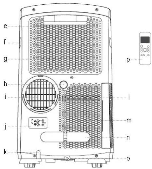
Figure 2
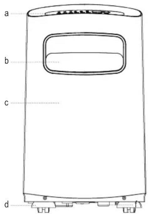
Front Rear
a. Control Panel
b. Horizontal Louver Blade
c. Panel
d. Caster
e. Upper Air Filter (behind the grille)
f. Handle (both sides)
g. Upper Air Intake
h. Drain Outlet
i. Air Outlet
j. Power Plug Socket
k. Power Cord Outlet
I. Lower Air Filter (behind the grille)
m. Lower Air Intake
n. Power Cord Buckle
o. Bottom Tray Drain Outlet
p. Remote Control
▲ NOTE: Exhaust hose and other installation accessories should not be discarded.
INSTALLATION INSTRUCTIONS
TOOLS NEEDED
• Medium Philips screwdriver
- Tape measure or ruler
- Knife or scissors
- Saw (optional, to shorten window adaptor for narrow windows)
ACCESSORIES
Your Window Installation Kit fits hung or sliding windows 26.5-48" (67.5-123cm) and can be shortened for smaller windows.
| Part Description Quantity | ||
| [cxwa] | Unit Adaptor 1 pc | |
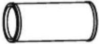 | Exhaust Hose | 1 pc |
 | Window Slider Adaptor 1 pc | |
 | Bolt 1 pc | |
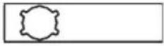 | Window Slider A 1 pc | |
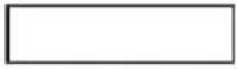 | Window Slider B 1 pc | |
 | Foam Seal A (Adhesive) 2 pc | |
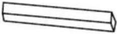 | Foam Seal B (Adhesive) 2 pc | |
 | Foam Seal C (Non-Adhesive) 1 pc | |
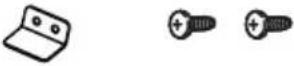 | Security Bracket and 2 Screws 1 set | |
| Drain Hose 1 pc | ||
 | Drain Hose Adaptor(only for heat pump mode) | 1 pc |
 | Power Cord Buckle 1 pc | |
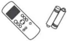 | Remote Controller and Battery | 1 set |
LOCATION
Your installation location should meet the following requirements:
- Make sure that you install your unit on a level surface to minimize noise and vibration.
- The unit must be installed near a grounded plug, and the Collection Tray Drain (found on the back of the unit) must be accessible.
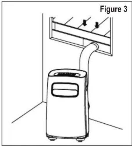
- The unit should be located at least 12" (30cm) from the nearest wall to ensure proper air conditioning.
- DO NOT cover the Intakes, Outlets or Remote Signal Receptor of the unit, as this could cause damage to the unit.
natural_image
Line drawing of a portable air conditioner unit with airflow direction arrows, labeled Figure 3 (no text or symbols on the device itself)WINDOW INSTALLATION KIT
- Preparing the Exhaust Hose Assembly: Press the exhaust hose into the window slider adaptor and unit adaptor and clamp with the buckles of the adaptor.
- Attach the Exhaust Hose Assembly to the Unit: Align the hook on the Unit Adaptor with the Hole Seat on the back of the unit and insert into lower groove, then attach Hook to the Hole Seat.
- Prepare the Adjustable Window Slider: Measure the size of your window opening. If needed, cut the window slider to the correct length. You may need both window sliders, in which case, slide Window Slider B into Window Slider A, adjust to correct size, and use the bolt to fasten the window sliders together.
INSTALLION
Exhaust Hose Exhaust Hose Assembly
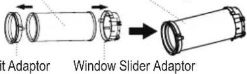
Figure 4
Hook
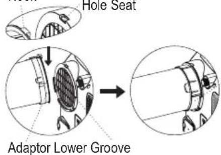
Figure 5
Make sure the adaptor is inserted into the lower groove of the air outlet.

Figure 6
▲ NOTE: Once the Exhaust Hose Assembly and Adjustable Window Slider are prepared, install according to the type of window you are using.
| Type 1: Hung Window Installation | |||
| 1 | 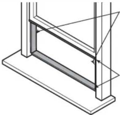 | Foam seal B(Adhesive type-shorter) | Cut the adhesive foam seal A and B strips to the proper lengths, and attach them to the window sash and frame as shown. |
| Foam seal A(Adhesive type) | |||
| 2 | 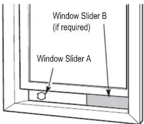 | Insert the window slider assembly into the window opening. |
| 3 | 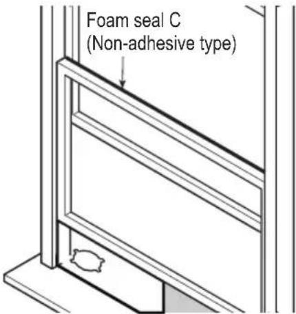 | Cut the non-adhesive foam seal C strip to match the width of the window. Insert the seal between the glass and the window frame to prevent air and insects from getting into the room. |
| 4 | 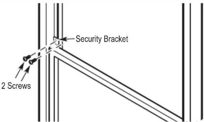 | If desired, install the security bracket with 2 screws as shown. |
| 5 | 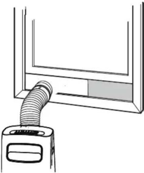 | Insert the window slider adaptor into the hole of the window slider. |
| Type 2: Sliding Window Installation | ||
| 1 | Foam seal B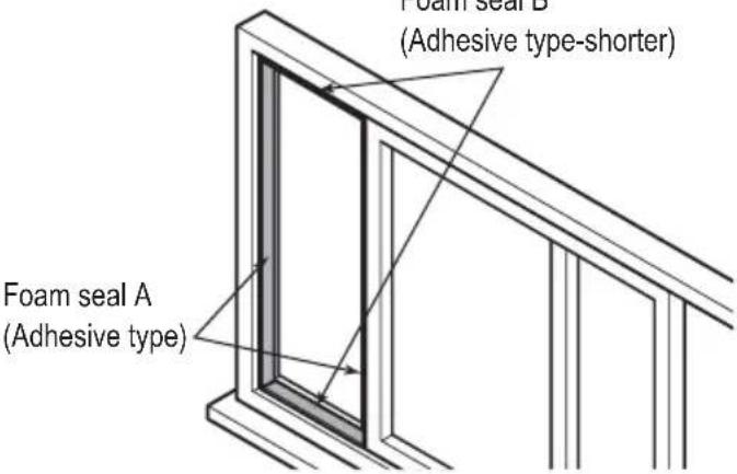 | Cut the adhesive foam seal A and B strips to the proper lengths, and attach them to the window sash and frame as shown. |
| 2 | 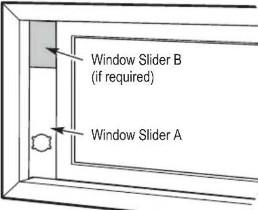 | Insert the window slider assembly into the window opening. |
| 3 | 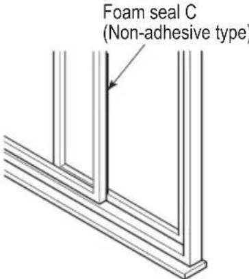 | Cut the non-adhesive foam seal C strip to match the window height. Insert the foam seal between the glass and the window frame to prevent air and insects from getting into the room. |
| 4 | 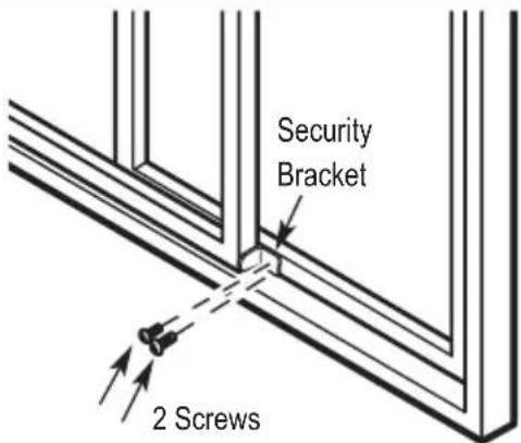 | If desired, install the security bracket with 2 screws as shown. |
| 5 | 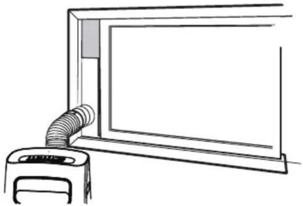 | Insert the window slider adaptor into the hole of the window slider. |
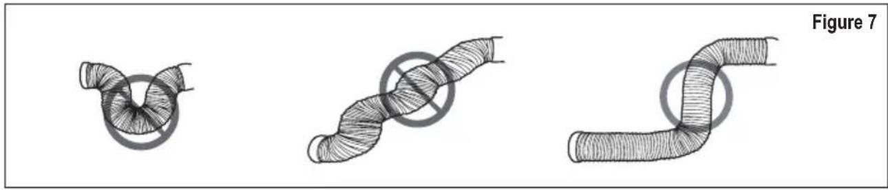
▲ NOTE: To ensure proper function, DO NOT overextend or bend the hose. Make sure that the air outlet of the exhaust hose has a clearance of about 20 in. (48cm). These illustrations are for explanation only, your air conditioner may be slightly different.
natural_image
Three hand-drawn pipe illustrations showing different types of coiled or twisted structures, labeled Figure 7 (no text or symbols on the diagrams themselves)REMOTE CONTROL
Before you begin using your new air conditioner, make sure to familiarize yourself with the remote control. The following is a brief introduction to the remote control itself. For instructions on how to operate your air conditioner, refer to the OPERATING INSTRUCTIONS section of this manual.
For best results, make sure you are pointing the remote control at the air conditioner. The remote has a range of about 26' (8m), and there will be a beep from the A/C unit when the remote signal is received. Anything obstructing a direct line between the remote and the unit, as well as direct sunlight, may interfere with the signal.
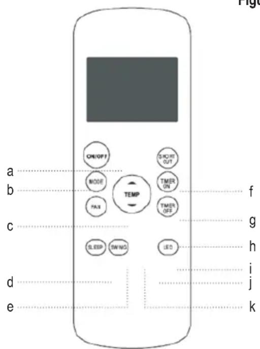
FUNCTION BUTTONS
- Button designs on your unit may differ slightly from the example shown. If the unit does not have a particular function, pressing that function button on the remote control will have no effect.
- See OPERATING INSTRUCTIONS section for more detailed information on the functions controlled by the remote control.
a. ON/OFF: Turns the unit on and off.
b. MODE: Cycles through the modes
c. FAN: Changes the fan speed
d. SLEEP: Starts the sleep mode
e. SWING: Starts and stops louvers
f. TEMP: Adjusts temperature up or down. Pressing up and down arrows together for 3 sec will change display from F to C.
g. SHORT CUT: Sets and activates pre-sets
- Used to save the current settings or resume previous settings.
- Push for more than 2 seconds, the system will automatically save the current operation settings including operating mode, setting temperature, fan speed level and sleep feature (if activated).
- Push this button when unit is on and the system will automatically restore the saved settings including operating mode, setting temperature, fan speed level and sleep feature (if activated).
h. TIMER ON/OFF: Sets timer to turn unit on or off.
i. LED: Turns units LED Display on or off.
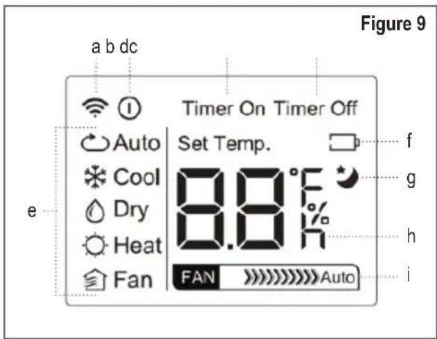
REMOTE CONTROL DISPLAY
a. Transmission Indicator: Lights up when remote sends signal to unit.
b. ON/OFF Display: Appears when the unit is turned on, and disappears when it is turned off.
c. TIMER ON Display: Displays when TIMER ON is set.
d. TIMER OFF Display: Displays when TIMER OFF is set.
e. Mode Display: Displays the mode "AUTO" – "COOL" – "DRY" – "HEAT" – "FAN".
f. Battery Display: Low Battery detection
g. Sleep Display: Displays when Sleep function is activated.
h. Fan Speed Display: Displays selected Fan Speed ">>>>>>" (HIGH) - ">>>>>>" (MED) - ">>> (LOW). This display is blank when set to AUTO speed.
i. Temperature/Timer Display: Displays the set temperature by default, or timer setting when using TIMER ON/OFF functions. This display is blank when operating in FAN Mode.
• Temperature Range: 62°F – 86°F (17°C - 30°C)
- Timer Setting Range: 0 – 24 hours
INSERTING AND REPLACING BATTERIES
Your remote uses two AAA batteries. To install or replace batteries:
- Slide the cover on the back of the remote downward, exposing the battery compartment.
- Insert the batteries, making sure the (+) and (-) ends of the batteries match the symbols inside the battery compartment.
- Slide the battery cover back into place.
NOTE: For optimum performance, do not mix old and new batteries.
It is recommended to remove the batteries if the remote will not be used for more than 2 months. Always be sure to properly dispose of old batteries.
The device complies with the local national regulations. In Canada, it complies with CAN ICES-3(B)/NMB-3(B). In the USA, this device complies with part 15 of the FCC Rules. Operation is subject to the following two conditions: (1) This device may not cause harmful interference, and (2) this device must accept any interference received, including interference that may cause undesired operation.
This equipment has been tested and found to comply with the limits for a Class B digital device, pursuant to part 15 of the FCC Rules. These limits are designed to provide reasonable protection against harmful interference in a residential installation. This equipment generates, uses and can radiate radio frequency energy and, if not installed and used in accordance with the instructions, may cause harmful interference to radio communications. However, there is no guarantee that interference will not occur in a particular installation. If this equipment does cause harmful interference to radio or television reception, which can be determined by turning the equipment off and on, the user is encouraged to try to correct the interference by one or more of the following measures:
- Reorient or relocate the receiving antenna.
- Increase the separation between the equipment and receiver.
- Connect the equipment into an outlet on a circuit different from that to which the receiver is connected.
- Consult the dealer or an experienced radio/TV technician for help.
Changes or modifications not approved by the party responsible for compliance could void user's authority to operate the equipment. 14
OPERATING INSTRUCTIONS
CONTROLS
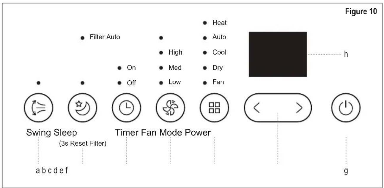
a. Swing button (For models with auto swing feature): Used to initiate the Auto swing feature. When the function is ON, press the SWING button to stop the louver at the desired angle.
b. Sleep / Filter button: Used to initiate the SLEEP/ECO operation.
NOTE: After 250 hours of operation, the filter indicator lights remind you to clean the Air Filter for more efficient operation. Press this button for 3 seconds to cancel the reminder.
c. Timer button: Used to initiate the AUTO ON start time and AUTO OFF stop time program, use with the + & - buttons. The timer on/off indicator light illuminates under the timer on/off settings.
d. Fan button: Controls the fan speed. Press to select the speed in four steps-LOW, MED, HIGH and AUTO. The fan speed indicator light will show the setting.
e. Mode button: Selects the operating mode. Each time you press the button, a mode will change from AUTO - COOL - DRY - FAN - HEAT. The mode indicator light indicates what mode is set.
f. Down (<) and Up (>) buttons: Used to adjust temperature settings in 1°F/1°C increments in a range of 62°F/17°C to 86°F/30°C or the TIMER setting in a range of 0\~24hrs.
g. NOTE: The control is capable of displaying temperature in Fahrenheit or Celsius. To change from F to C, press and hold the Up and Down buttons at the same time for 3 seconds.
h. Power button: Used to turn the unit On or Off.
i. LED Display: Displays the set temperature in °F or °C and the Auto-timer settings. While on DRY and FAN modes, it shows the room temperature.
Error Codes
• E1: Room temperature sensor error.
• E2: Evaporator temperature sensor error.
• E3: Condenser temperature sensor error.
• E4: Display panel communication error.
• E7: Zero-crossing malfunction.
Protection Code
• P1: Water tray is full.
▲ NOTE: If the display shows one of the above codes turn off and unplug the unit, and check for any obstructions or empty the water tray, then restart. If code is still present, turn off again and unplug, and contact customer service or service technician for assistance.
OPERATING
Cool Mode
- Press the "MODE" button until the "COOL" indicator lights.
- Press the ADJUST buttons “+” or “-” to select your desired room temperature. The temperature can be set within a range of 62°F\~86°F /17°C\~30°C.
- Press the "FAN SPEED" button to choose the fan speed.
Heat Mode
- Press the "MODE" button until the "HEAT" indicator lights.
- Press the ADJUST buttons “+” or “-” to select your desired room temperature. The temperature can be set within a range of 62°F\~86°F (17°C\~30°C).
- Press the "FAN SPEED" button to choose the fan speed. For some models, the fan speed cannot be adjusted under HEAT mode.
Dry Mode
- Press the "MODE" button until the "DRY" indicator lights.
- The fan motor operates at LOW speed and cannot be changed. You cannot adjust the temperature in this mode.
- Keep windows and doors closed and do not run the exhaust duct to window.
Auto Mode
- Press the "MODE" button until the "AUTO" indicator lights.
- When in AUTO mode, cooling, heating (if applicable), or fan only will be automatically selected to maintain the room temperature the unit is set for.
- When in AUTO mode, fan speed cannot be changed.
Fan Mode
- Press the "MODE" button until the "FAN" indicator lights.
- Press the "FAN SPEED" button to choose the fan speed. The temperature cannot be adjusted.
- Do not run the exhaust duct to window.
Timer Mode
- If the unit is on, pressing the Timer button once will start the Auto-Off stop program, and the Off
- indicator light above the timer button will be lit. Pushing the Timer button again within 5 seconds will switch to the Auto-On start function, and the On indicator will be lit.
- If the unit is off, pushing Timer will start the Auto-On start feature, and pushing it again within 5 seconds will switch it to the Auto-Off stop feature.
- Press or hold the UP or DOWN button to set the Auto time in 0.5 hour increments, up to 10 hours, then in 1 hour increments up to 24 hours. The control will count down the time remaining until starting or stopping.
▲ NOTE: The Timer feature counts down the time set for On or Off. For example, if it is currently 1:30pm, setting the unit to Timer On for 4 hours will set the unit to turn on at 5:30pm.
- The system will automatically revert back to display the previous temperature setting if no button is pressed within 5 seconds.
- Turning the unit ON or OFF at any time or adjusting the timer setting to 0.0 will cancel the Auto Start/Stop timer program.
- If a malfunction occurs, the Auto Start/Stop program will be cancelled.
NOTE: When using the Remote Control to set Timer Mode, push the TIMER ON or TIMER OFF buttons to adjust the time in 0.5 hour increments, up to 10 hours, then in 1 hour increments up to 24 hours. To set both an Auto-On and Auto-Off timers, first set the Timer On to the desired length of time, wait 3 seconds, then set the desired Timer Off using the corresponding buttons.
Sleep/Eco Mode
- Pressing the Sleep button in COOL mode will allow the set temperature to increase by 2^ / 1^ after 30 minutes, and again after another 30 minutes. If unit is in HEAT mode, the set temperature will decrease the same amount in the same time. The unit will maintain the new temperature for 7 hours, and then return to the previously selected temperature setting.
▲ NOTE: This feature is not available in FAN or DRY mode.
Other Features
- Air Flow Direction Adjustment: When the unit is turned On, the louver opens fully. Press the SWING button on the control panel or remote control to move the louver up and down automatically.
▲ NOTE: On units that have the SWING feature, DO NOT adjust the louver manually.
▲ NOTE: When using the Remote Control, each time the Swing button is pushed, the angle of the louvers adjust 6 degrees. Push and hold Swing button for about 2 seconds to activate the auto-swing feature. - Auto-Restart: If the power to the unit is unexpectedly lost or shut off, the unit will maintain previous settings when it is restored.
- 3 Minute Delay: When the unit is stopped, shut off, or loses power, it cannot be restarted for 3 minutes to protect the cooling system. Operation will automatically start after 3 minutes.
DRAINING THE WATER
There are two ways to remove water collected while the unit is running.
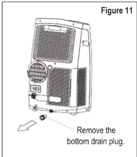
- Manually empty the water bucket: When the water level of the bottom tray reaches a predetermined level, the unit beeps 8 times and the display will show "P1". The air conditioning / dehumidification process will immediately stop, however the fan motor will continue to run (this is normal). Turn off and unplug the unit, carefully move it to a drain location, remove the bottom drain plug and let the water drain out. Reinstall the bottom drain plug and restart the unit until the "P1" symbol disappears. If the error repeats, call for service.
▲ NOTE: Be sure to reinstall the bottom drain plug firmly to prevent leakage before using the unit.
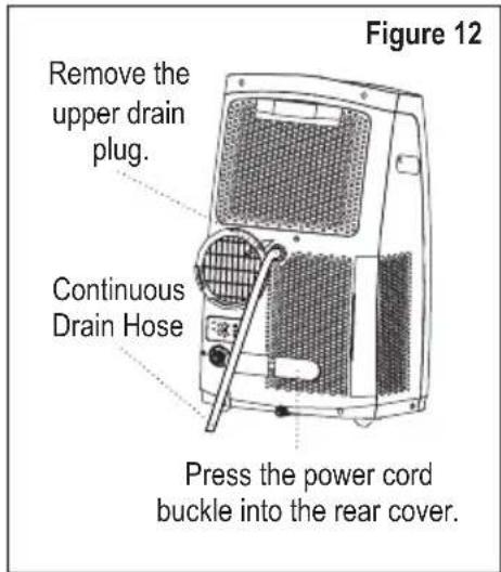
- Continuous Draining: To drain continuously to a floor drain, connect the drain connector (5/8" universal female mender) to the drain hose. Make sure the connection is tight and there is no leak and place the open end of the hose directly over the drain in your basement floor. The water hose should slope downward to allow the water to flow out smoothly.
CARE AND MAINTENANCE
⚠ WARNING: Turn the unit off and remove the plug from the wall outlet before maintenance or cleaning.
- DO NOT use flammable liquids or chemicals to clean the unit.
- DO NOT immerse in or spray with water to clean.
- DO NOT operate the unit if the power cord is damaged.
- The water bucket should be cleaned every few weeks or as needed. DO NOT leave water in the bucket when unit is not being used. ALWAYS empty before storage or as soon as "P1" is displayed.
CLEAN THE AIR FILTERS
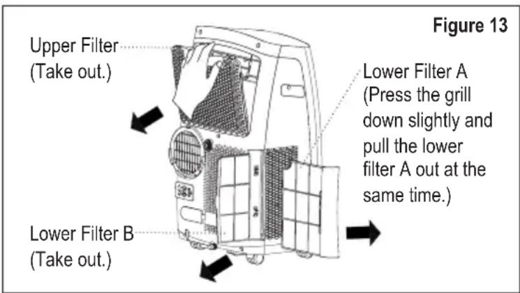
- Clean the air filters with water at least once every 2 weeks for optimal performance, or as needed. DO NOT use the unit with the filters missing.
- If used in a household with animals, periodically wipe down the grills to prevent animal fur from blocking airflow.
CLEANING THE PORTABLE AIR CONDITIONER
- Clean the unit using a damp, lint-free cloth and mild detergent (if needed) and dry off with a dry, lint-free cloth.
STORAGE
- Drain the unit's water collection tray according to the instructions.
- Run the unit on FAN mode for 12 hours in a warm room to dry it and prevent mold. Turn off the appliance and unplug it. Clean the air filter according to the instructions above. Reinstall the clean, dry filter before storing.
- Remove the batteries from the remote control.
- Be sure to store the unit in a cool, dark place. Exposure to direct sunshine or extreme heat can shorten the lifespan of the unit.
TROUBLESHOOTING
Please check the following before calling for service.
| Problem Possible Cause | Troubleshooting | |
| Unit does not turn on when pressing ON/OFF button. | P1 Error Code | The Water Collection Tray is full.Turn off and unplug the unit, drain the water from the Water Collection Tray and restart the unit. |
| In COOL mode: Room temperature is lower than the set temperature. | Reset the temperature. | |
| Unit does not cool Well. | The air filter is blocked or dirty. | Turn off the unit and clean the filter according to instructions. |
| Exhaust hose is not connected or is blocked. | Turn off the unit, disconnect the hose, check for blockage and reconnect the hose. | |
| The unit is low on Refrigerant. Call customer service or service technician. | ||
| Temperature setting is too High. Decrease the set temperature. | ||
| Windows or doors in room are open. Make sure all windows and doors are closed. | ||
| The room area is too large. Double-check the cooling area. | ||
| There are heat sources inside the room. | Remove the heat sources if possible. | |
| The unit is noisy and vibrates too much. | The ground or the unit is not level | Place the unit on a flat, level surface, make sure unit is level. |
| The air filter is blocked or dirty. | Turn off the unit and clean the filter according to instructions. | |
| The unit makes a gurgling sound. | This sound is caused by the flow of refrigerant inside the unit. | This is normal. |
norpole
LIMITED WARRANTY
Norpole, Inc. warrants each new PORTABLE AIR CONDITIONER to be free from defects in material and workmanship and agrees to remedy any such defect or to furnish a new part(s) (at the company's option) for any part(s) of the unit that has failed during the warranty period. Parts and labor expenses are covered on this unit for a period of one year from the date of purchase. In addition, Norpole, Inc. warrants the compressor (parts only) to be free from defects in material and workmanship for a period of 5 years. The consumer is responsible for all labor and transportation expenses related to the diagnosis and replacement of the compressor after the initial one-year warranty expires. In the event that the unit requires replacement or refund under the terms of this warranty, the consumer is responsible for all transportation expenses to return the unit to our factory prior to receiving a replacement unit or refund. A refund or replacement will be issued at the discretion of Norpole, Inc.. A copy of the dated sales receipt/invoice is required to receive warranty service or a refund.
This warranty covers appliances in use within the contiguous United States, Alaska, Hawaii and Puerto Rico. The warranty does not cover the following:
- Damages due to shipping damage or improper installation.
- Damages due to misuse or abuse.
- Content losses due to failure of the unit.
- Inside components such as the filter, etc.
• Repairs performed by unauthorized service agents. - Service calls that do not involve defects in material and workmanship, such as instructions on proper use of the product or improper installation.
- Replacement or resetting of house fuses or circuit breakers.
- Failure of this product if used for purposes other than its intended purpose.
- Disposal costs for any failed unit not returned to our factory.
- Any delivery or installation costs incurred as the result of a unit that fails to perform as specified.
- Expenses for travel and transportation for product service if your appliance is located in a remote area where service by an authorized service technician is not available.
- The removal and reinstallation of your appliance if it is installed in an inaccessible location or is not installed in accordance with published installation instructions.
- Refunds for non-repairable products are limited to the price paid for the unit per the sales receipt.
- This warranty is non-transferable. This warranty applies only to the original purchaser and does not extend to any subsequent owners.
LIMITATIONS OF REMEDIES AND EXCLUSIONS
Product repair in accordance with the terms herein, is your sole and exclusive remedy under this limited warranty. Any and all implied warranties including merchantability and fitness for a particular purpose are hereby limited to one year or the shortest period allowed by law. Norpole, Inc. is not liable for incidental or consequential damages and no representative or person is authorized to assume for us any other liability in connection with the sale of this product. Under no circumstances is the consumer permitted to return this unit to the factory without the prior written consent of Norpole, Inc..
Some states prohibit the exclusion or limitation of incidental or consequential damages, or limitations on implied warranties. This warranty gives you specific legal rights, and you may also have other rights which vary from state to state.
Model Parts & Labor Compressor (Part Only) Type of Service
NPPAC12HKM One-Year Five Years Carry In
For Service or Assistance please call 888-775-0202 or visit us on the web at www.mcappliance.com.

natural_image
Line drawing of a rectangular electronic device with a recessed top and side-mounted base (no text or symbols)norpole
REGISTRO DEL PRODUCTO
natural_image
Line drawing of a portable air conditioner unit with airflow direction indicator (no text or symbols on device)natural_image
Three hand-drawn pipe illustrations showing different types of twisted or coiled structures, labeled Figura 7 (no text or symbols on the diagrams themselves)CONTROL REMOTO

- norpole
- PRODUCT REGISTRATION
- CONTENTS
- IMPORTANT SAFETY INSTRUCTIONS
- EXPLANATION OF SYMBOLS
- READ AND FOLLOW THIS SAFETY INFORMATION CAREFULLY SAVE THESE INSTRUCTIONS
- SPECIFICATIONS
- PARTS IDENTIFICATION
- INSTALLATION INSTRUCTIONS
- TOOLS NEEDED
- ACCESSORIES
- LOCATION
- WINDOW INSTALLATION KIT
- INSTALLION
- REMOTE CONTROL
- FUNCTION BUTTONS
- REMOTE CONTROL DISPLAY
- INSERTING AND REPLACING BATTERIES
- OPERATING INSTRUCTIONS
- CONTROLS
- Error Codes
- Protection Code
- OPERATING
- Cool Mode
- Heat Mode
- Dry Mode
- Auto Mode
- Fan Mode
- Timer Mode
- Sleep/Eco Mode
- Other Features
- DRAINING THE WATER
- CARE AND MAINTENANCE
- CLEAN THE AIR FILTERS
- CLEANING THE PORTABLE AIR CONDITIONER
- STORAGE
- TROUBLESHOOTING
- LIMITED WARRANTY
- LIMITATIONS OF REMEDIES AND EXCLUSIONS
- REGISTRO DEL PRODUCTO
- CONTROL REMOTO
Brand : Norpole
Model : NPPAC12HKM
Category : Air-conditioner