
765H80LB - Home Fan BROAN - Free user manual and instructions
Find the device manual for free 765H80LB BROAN in PDF.


| Product Type | Ceiling-mounted heater, ventilator, and light fixture |
| Recommended Use | Residential bathrooms, tub/shower areas |
| Installation Location | Ceiling only; not for wall or floor mounting |
| Ceiling Pitch | Up to 12/12 pitch |
| Minimum Clearance | At least 6 inches from floor or adjacent wall; 3 feet (0.9 m) from combustible materials (front, sides, rear) |
| Electrical Rating | 120 VAC, 60 Hz, requires dedicated 20 A circuit, 12 AWG wire |
| Power Cord | Hardwired; not supplied with plug |
| Heater Element Type | Permanently lubricated, no oiling required |
| Light Bulb Type | A19 shape, E26 base LED, max 14 watts |
| Light Lens | Snap-on removable lens for bulb replacement |
| Ventilation | Ducted exhaust to outside; damper included |
| Control Type | Separate wall switch or timer (not included) |
| Dimensions (Housing) | Fits standard 16-inch or 24-inch joist centers |
| Weight | Approximately 8 lbs (3.6 kg) |
| Sound Level | Quiet operation (not specified) |
| Safety Certifications | UL Listed (implied by code compliance) |
| Warranty | Refer to website or call 800-558-1711 (Broan) / 888-336-6151 (NuTone) |
| Maintenance | Monthly cleaning: vacuum grille openings with soft brush; do not immerse in water |
| Included Components | Housing, fan assembly, heater assembly, grille, light reflector, lens, mounting brackets, damper/duct connector, hardware |
Frequently Asked Questions - 765H80LB BROAN
User questions about 765H80LB BROAN
0 question about this device. Answer the ones you know or ask your own.
Ask a new question about this device
Download the instructions for your Home Fan in PDF format for free! Find your manual 765H80LB - BROAN and take your electronic device back in hand. On this page are published all the documents necessary for the use of your device. 765H80LB by BROAN.
USER MANUAL 765H80LB BROAN
For Warranty Statement, Service Parts, Technical Support, or to Register your product, please visit our website or call Broan.com 800-558-1711 or NuTone.com. 888-336-6151.
READ AND SAVE THESE INSTRUCTIONS
IMPORTANT INSTRUCTIONS
READ ALL INSTRUCTIONS BEFORE INSTALLING OR USING THIS HEATER.
To reduce the risk of fire, electric shock, or injury to persons, observe the following:
- Use this unit only in the manner intended by the manufacturer. If you have questions, contact the manufacturer at the address or telephone number listed in the warranty.
- Before servicing or cleaning unit, switch power off at service panel and lock the service disconnecting means to prevent power from being switched on accidentally. When the service disconnecting means cannot be locked, securely fasten a prominent warning device, such as a tag, to the service panel.
- Installation work and electrical wiring must be done by a qualified person(s) in accordance with all applicable codes and standards, including fire-rated construction codes and standards.
- When cutting or drilling into wall or ceiling, do not damage electrical wiring and other hidden utilities.
- This heater is hot when in use. To avoid burns, do not let bare skin touch hot surfaces. Keep combustible materials, such as furniture, pillows, bedding, papers, clothes, etc. and curtains at least 3 feet (0.9 m) from the front of the heater.
-
Extreme caution is necessary when any heater is used by or near children or invalids and whenever the heater is left operating and unattended.
-
Do not operate any heater after it malfunctions. Disconnect power at service panel and have heater inspected by a reputable electrician before reusing.
-
Do not use outdoors.
-
To disconnect heater, turn controls to off, and turn off power to heater circuit at main disconnect panel (or operate internal disconnect switch, if provided).
-
Do not insert or allow foreign objects to enter any ventilation or exhaust opening, as this may cause an electric shock or fire, or damage the heater.
-
To prevent a possible fire, do not block air intakes or exhaust in any manner.
- A heater has hot and arcing or sparking parts inside. Do not use it in areas where gasoline, paint, or flammable vapors or liquids are used or stored.
-
Use this heater only as described in this manual. Any other use not recommended by the manufacturer may cause fire, electric shock, or injury to persons.
-
This product must be grounded.
-
Do not install heater in a tub or shower enclosure.
-
This product is designed for ceiling installation only. This product is designed for installation in ceilings up to a 12/12 pitch. Ductwork must point up. DO NOT MOUNT THIS PRODUCT IN A WALL.
-
Install heater at least 6 inches from floor or any adjacent wall.
-
Do not connect heater to dimmer switch or speed control.
-
Provide a separate 20 AMP circuit. Use 12 GA. power cable of type which meets code.
-
For greatest efficiency, install heater so heat is directed toward tub or shower area. Avoid directing toward walls or windows.
SAVE THESE INSTRUCTIONS
PREPARATION
- Make sure the heater assembly is unplugged from the RED receptacle.
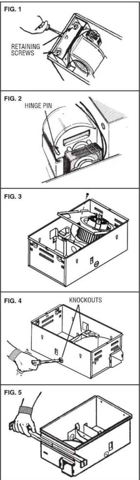
- Loosen the two retaining screws on the inside of the heater discharge opening. Place a screwdriver tip between the outer wall of the discharge opening and the fan housing. Gently pry outward until the exhaust discharge slips off the support lip on the outer housing. (FIG. 1)
- Unhook hinge pins and lift heater assembly out of housing. (FIG. 2)
- Unplug the fan assembly from the BLACK receptacle. Remove the plastic bag and set it aside.
- Remove the mounting screw and carefully lift the fan assembly out of the housing. (FIG. 3)
- Refer to the wiring diagram on the next page. Remove appropriate knockout(s) by inserting a screwdriver blade into slots and bending it back and forth to break tabs. (FIG. 4)
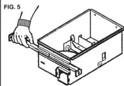
- Insert the adjustable mounting brackets into the bracket channels on the housing. (FIG. 5)
CAUTION: REMOVE THE SHIPPING RING FROM THE HEATER BLOWER INLET BEFORE OPERATING THE HEATER.
INSTALLATION
WARNING: To reduce the risk of fire, do not store or use gasoline or other flammable vapors and liquids in the vicinity of the heater.
CAUTION: High temperature, risk of fire, keep electrical cords, drapery, furnishings, and other combustibles at least 3 feet (0.9 m) from the front of the heater and away from the side and rear.
- For best results, choose a location which allows fan to be vented outside with the shortest possible duct run and the fewest number of elbows.
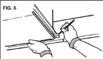
- Position unit between joists and extend mounting brackets. Position brackets such that the bottom edge of housing will be flush with finished ceiling. Mark the top of keyhole slot on all four mounting brackets. (FIG. 6)
- Remove unit temporarily, and drive nails partially into joists at all four marked locations. (FIG. 7)
- Hang unit from nails and use embossed measuring guides to check if unit will be flush with finished ceiling. Drive nails tight. For wide joist centers: A #8 x 3/8 self-tapping screw can be used to join extended brackets together and create a rigid mount. To ensure a noise-free mount, crimp the bracket channels tightly around mounting brackets. (FIG. 8)
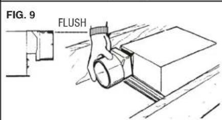
- Snap the damper/duct connector onto housing. Make sure that tabs on the connector lock in housing slots. (Top of damper/duct connector will be flush with top of housing.) (FIG. 9)
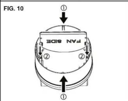
NOTE: Make sure damper flap is in place inside of duct connector. If it is not: ① Squeeze top and bottom of connector to ② snap flap back into place. (FIG. 10)
Installation work and electrical wiring must be done by a qualified person(s) in accordance with all applicable codes and standards, including fire-rated construction codes and standards.
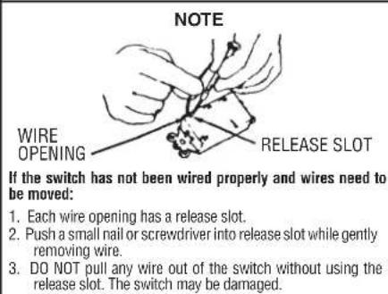
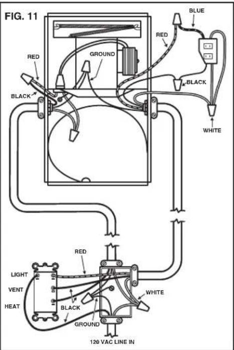
- Wire unit according to Figure 11.
- Replace heater assembly removed in STEP 3 and plug it into RED receptacle. Direct wires away from blower inlet.
- Replace fan assembly removed in STEP 5 and plug it into BLACK receptacle.
natural_image
Illustration of hands using a tool to cut or mark a metal strip, no text or symbols present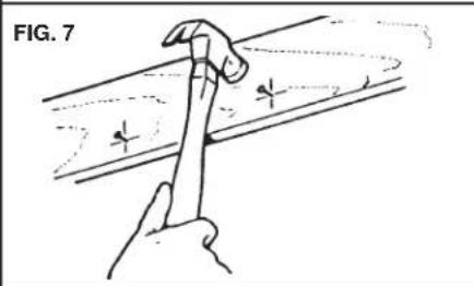
natural_image
Illustration of a hand holding a tool over a curved surface, with no visible text or symbols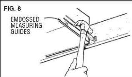
INSTALLATION (CONT'D)
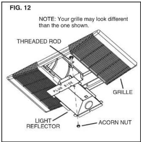
CAUTION: To avoid the possibility of overheating and/or fire, the grille must be installed as shown in FIG. 12. Acorn nut must attach to threaded rod through proper hole in light reflector.
- Slide the light reflector into opening in grille and plug into WHITE receptacle. Use acorn nut from plastic bag to attach grille reflector assembly to threaded rod on housing. Tighten securely using pliers or nut driver. Install an A19 shape, E26 base LED light bulb - 14 Watt (max.). (FIG.12)
NOTE: Light turning off or blinking may indicate an improper lamp wattage or type.
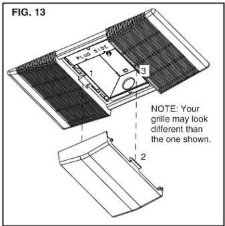
- Install light lens by 1) hooking one of its tabs into notch in grille/REFOR assembly; 2) apply light pressure to other tab with fingertips and 3) snap into place. (FIG. 13)
OPERATION
Before using heater, make sure heater has been properly installed according to installation steps beginning with the "PREPARATION" section on page 1.
NOTE: Light turning off or blinking may indicate an improper lamp wattage or type.
MAINTENANCE
The following maintenance and cleaning tasks can be performed by the user. All other servicing must be performed by an authorized technician. If you have any questions, please consult with our customer service department at: 800-558-1711.
TO REPLACE BULB
Remove lens by gently depressing sides and pull down. Use an A19 shape, E26 base LED bulb rated up to 14 watts only.
NOTE: Light turning off or blinking may indicate an improper lamp wattage or type.
LUBRICATION
The heater is permanently lubricated and never needs oiling or disassembly.
CLEANING
Clean heater once a month as follows:
- Turn off power at service panel.
- Make sure heating element is cool.
- Use a soft brush attachment to gently vacuum grille openings or wipe grille clean with a soft cloth.
- Restore power.
CAUTION: METAL AND ELECTRICAL PARTS SHOULD NEVER BE IMMERSED IN WATER.
CALENTADOR/VENTILADOR/LÁMPARA
natural_image
Technical line drawing of an open industrial machine casing with internal components (no text or symbols)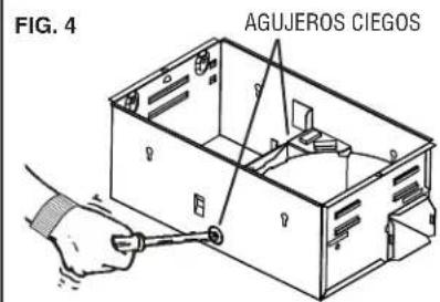
natural_image
Line drawing of a hand using a tool to handle an open box with internal compartments (no text or symbols)INSTALACIÓN
natural_image
Illustration of hands using a tool to cut or mark a line, no text or symbols present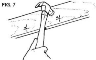
natural_image
Hand holding a hammer striking a surface with cross marks (no text or symbols)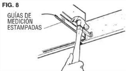
- READ AND SAVE THESE INSTRUCTIONS
- IMPORTANT INSTRUCTIONS
- READ ALL INSTRUCTIONS BEFORE INSTALLING OR USING THIS HEATER.
- SAVE THESE INSTRUCTIONS
- PREPARATION
- CAUTION: REMOVE THE SHIPPING RING FROM THE HEATER BLOWER INLET BEFORE OPERATING THE HEATER.
- INSTALLATION
- INSTALLATION (CONT'D)
- OPERATION
- MAINTENANCE
- TO REPLACE BULB
- LUBRICATION
- CLEANING
- CALENTADOR/VENTILADOR/LÁMPARA
- INSTALACIÓN
Brand : BROAN
Model : 765H80LB
Category : Home Fan