
744L - Home Fan BROAN - Free user manual and instructions
Find the device manual for free 744L BROAN in PDF.


| Product Type | Whole House Fan |
| Brand | Broan |
| Model | 744L |
| Dimensions (W x D x H) | 22 x 22 x 12 inches |
| Weight | 25 lbs |
| Power Supply | 120 V, 60 Hz, 2.5 A |
| Airflow | 1500 CFM |
| Noise Level | 50 dB |
| Speeds | 3 |
| Control | Thermostat and manual switch |
| Material | Galvanized steel housing |
| Shutters | Automatic |
| Installation | Ceiling mount |
| Warranty | 1 year limited |
| Maintenance | Clean blades and motor annually |
| Cleaning | Use damp cloth, no solvents |
| Safety | Do not install near heat sources |
| Spare Parts | Available from Broan |
| Repairability | Replace motor, blades, shutter assembly |
Frequently Asked Questions - 744L BROAN
User questions about 744L BROAN
0 question about this device. Answer the ones you know or ask your own.
Ask a new question about this device
Download the instructions for your Home Fan in PDF format for free! Find your manual 744L - BROAN and take your electronic device back in hand. On this page are published all the documents necessary for the use of your device. 744L by BROAN.
USER MANUAL 744L BROAN
RECESSED LED FAN / LIGHT
For Warranty Statement, Service Parts, Technical Support, or to Register your product, please visit our website or call: In the United States - Broan.com 800-637-1453 or NuTone.com 888-336-6151. In Canada - Broan.ca or NuTone.ca 877-896-1119

natural_image
Technical line drawing of a mechanical component with a cylindrical part inserted into a housing (no text or symbols)Page 1
READ AND SAVE THESE INSTRUCTIONS
WARNING


TO REDUCE THE RISK OF FIRE, ELECTRIC SHOCK, OR INJURY TO PERSONS, OBSERVE THE FOLLOWING:
- Use this unit only in the manner intended by the manufacturer. If you have questions, contact the manufacturer at the address or telephone number listed in the warranty.
- Before servicing or cleaning unit, switch power off at service panel and lock the service disconnecting means to prevent power from being switched on accidentally. When the service disconnecting means cannot be locked, securely fasten a prominent warning device, such as a tag, to the service panel.
- Installation work and electrical wiring must be done by a qualified person(s) in accordance with all applicable codes and standards, including fire-rated construction codes and standards.
- Sufficient air is needed for proper combustion and exhausting of gases through the flue (chimney) of fuel burning equipment to prevent backdrafting. Follow the heating equipment manufacturer's guideline and safety standards such as those published by the National Fire Protection Association (NFPA), and the American Society for Heating, Refrigeration and Air Conditioning Engineers (ASHRAE), and the local code authorities.
- When cutting or drilling into wall or ceiling, do not damage electrical wiring and other hidden utilities.
- Ducted fans must always be vented to the outdoors.
- Never place a switch where it can be reached from a tub or shower.
- A dimmer switch may be used to operate the light in this unit. Refer to the list of compatible dimmer switches on broan.com.
- Install this unit in a flat ceiling only.
- For use in non fire rated installations only.
- Not for use in environmental air handling spaces.
- If this unit is to be installed over a tub or shower, it must be marked as appropriate for the application and be connected to a GFCI (Ground Fault Circuit Interrupter) - protected branch circuit.
- Do not install in a ceiling thermally insulated to a value greater than R60.
- This unit must be grounded.
CAUTION

- For general ventilating use only. Do not use to exhaust hazardous or explosive materials and vapors.
- To avoid motor bearing damage and noisy and/or unbalanced impellers, use the cardboard protector (provided) to keep drywall spray, construction dust, etc. off power unit.
- Please read specification label on product for further information and requirements.
OPERATION
The fan and light can be operated using various combinations of on/off switches and controls:
• Fan and light controlled with single on/off switch
• Fan and light controlled with separate on/off switches
• Fan controlled with timer control
- Selectable fan CFM - 50 or 80
See "Connect Wiring" section for various wiring options.
CLEANING
To clean trim ring / baffle: Vacuum with a soft brush attachment or remove trim ring / baffle and clean with a soft cloth and mild soap or detergent. Dry thoroughly before reinstalling.
To clean inside of housing: Remove trim ring / baffle and vacuum inside of housing with a soft brush attachment.
MAINTENANCE
Motor is permanently lubricated. Do not oil or disassemble motor.
Installer: Leave this manual with the homeowner.
PLAN THE INSTALLATION

Typical Installation
The unit can be installed anywhere between ceiling joists using mounting brackets provided.
* Install in a flat ceiling only.

The ducting from this fan to the outside of the building has a strong effect on the air flow, noise and energy use of the fan. Use the shortest, straightest duct routing possible for best performance, and avoid installing the fan with smaller ducts than recommended. Insulation around the ducts can reduce energy loss and inhibit mold growth. Fans installed with existing ducts may not achieve their rated airflow.
Plan to supply the unit with proper line voltage and appropriate power cable.

Do not install in a cooking area.
The unit must not be installed above or inside the cooking area shown.
INSTALLATION

1. Install mounting brackets.
Slide the adjustable mounting brackets into the bracket channels on the housing.
Bend the tabs on the cardboard protector and insert protector into opening in housing.
NOTE: The cardboard protector shields the inside of the housing from drywall spray and construction dust. Do not remove it until after construction is completed.

2. Mark mounting location.
Position unit between joists and extend mounting brackets. IMPORTANT: Position brackets so there will be an 1/8" gap between bottom of housing and ceiling material. Mark the top of keyhole slot on all four mounting brackets.
natural_image
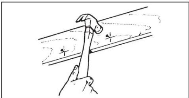
Hand holding a hammer striking a surface with dashed lines indicating motion (no text or symbols)3. Pound in nails.
Remove unit temporarily, and pound nails partially into joists at all four marked locations.

natural_image
Line drawing of a hand using a tool to lift or install a metal component (no text or symbols present)4. Hang and secure housing.
Hang unit from nails. Check to make sure that there will be a 1/8" gap between bottom of housing and ceiling material. Pound nails tight. For wide joist centers: A #8 x 3/8 self-tapping screw can be used to join extended brackets together and create a rigid mount. To ensure a noise-free mount, crimp the bracket channels tightly around mounting brackets.

5. Attach damper/duct connector.
Snap the damper/duct connector onto housing. Make sure that tabs on the connector lock in housing slots. (Top of damper/duct connector will be flush with top of housing.) Install ductwork.
NOTE: Make sure damper flap is in place inside of duct connector. If it is not: ① Squeeze top and bottom of connector to ② snap flap back into place.

6. Choose power cable direction.
Remove wiring plate. When re-attached, the wiring plate allows the power cable to enter unit horizontally or vertically.
7. Connect wiring.
Unit can be wired from outside of housing as shown. Use UL approved connectors to wire per local codes.
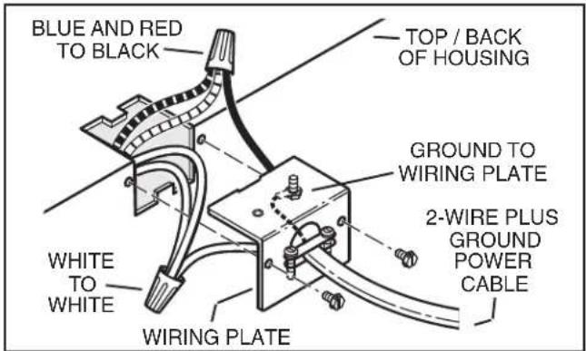
Fan and Light operated with single on/off switch

Fan operated with separate on/off switch or timer. Light operated with separate on/off switch.
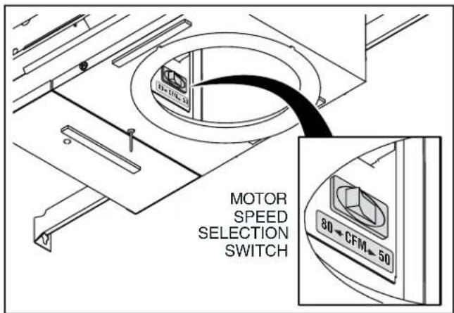
8. Select motor speed.
Use rocker switch to select 50 or 80 CFM, based on room size and desired sound level.

9. Finish ceiling.
Cut an opening in finished ceiling material for housing collar.
DO NOT INSTALL TRIM RING WHEN BAFFLE IS ALREADY ATTACHED TO FAN.

natural_image
Technical line drawing of a curved structural component with an upward force arrow, no text or symbols present10. Install optional trim ring to trim ring / baffle.
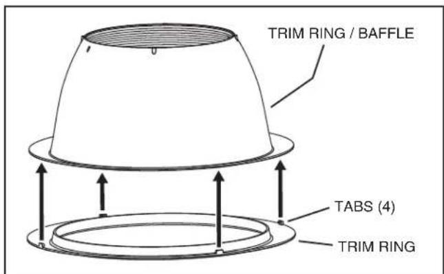
(Trim rings not included with Model 744L.)
Remove the cardboard protector from inside the housing collar.
Place trim ring over trim ring / baffle.
Place fingers directly above and below tab (as shown with arrows and squeeze to snap tab securely to trim ring / baffle.
Repeat for each of the 4 tab locations.

11. Attach trim ring / baffle to housing.
Use a pencil to insert one end of each spring into the holes on the lamp bracket. Center trim ring / baffle in ceiling opening.

natural_image
Line drawing of a hand holding a circular object with an arrow indicating rotational motion (no text or symbols)12. Install bulb. (Bulb not included with Model 744L.)

CAUTION - RISK OF FIRE: 75W MAX. LAMP
Use R30, BR30, PAR30L, or PAR30LN lamps only (75W Max.).
For wet locations (tub or shower) - use PAR30L or PAR30LN (75W Max.) lamp only. Use no other lamp types.
Do not install a lamp indentified for use only in enclosed luminaries.

CAUTION: Disconnect power at service entrance before cleaning, servicing, or selecting motor speed.
VENTILADOR CON LÁMPARA LED EMPOTRADO
natural_image
Technical drawing of a mechanical assembly with a bolt and flange (no text or symbols)Página 5
LEA Y CONSERVE ESTAS INSTRUCCIONES
ADVERTENCIA


PARA REDUCIR EL RIESGO DE INCENDIOS, DESCARGAS ELÉCTRICAS O LESIONES PERSONALES, SIGA LAS SIGUIENTES PRECAUCIONES:
natural_image
Line drawing of a hand using a hammer to cut a metal strip (no text or symbols)natural_image
Line drawing of a hand using a tool to cut or mark a metal strip (no text or symbols)natural_image
Technical line drawing of a mechanical component with downward and upward arrows indicating force or movement (no text or symbols)natural_image
Line drawing of a hand holding a circular object with an arrow indicating rotation (no text or symbols)

- RECESSED LED FAN / LIGHT
- READ AND SAVE THESE INSTRUCTIONS
- WARNING
- TO REDUCE THE RISK OF FIRE, ELECTRIC SHOCK, OR INJURY TO PERSONS, OBSERVE THE FOLLOWING:
- CAUTION
- OPERATION
- CLEANING
- MAINTENANCE
- Installer: Leave this manual with the homeowner.
- PLAN THE INSTALLATION
- INSTALLATION
- Install mounting brackets.
- Mark mounting location.
- Pound in nails.
- Hang and secure housing.
- Attach damper/duct connector.
- Choose power cable direction.
- Connect wiring.
- Select motor speed.
- Finish ceiling.
- Install optional trim ring to trim ring / baffle.
- Attach trim ring / baffle to housing.
- Install bulb. (Bulb not included with Model 744L.)
- CAUTION - RISK OF FIRE: 75W MAX. LAMP
- VENTILADOR CON LÁMPARA LED EMPOTRADO
- LEA Y CONSERVE ESTAS INSTRUCCIONES
- ADVERTENCIA
- PARA REDUCIR EL RIESGO DE INCENDIOS, DESCARGAS ELÉCTRICAS O LESIONES PERSONALES, SIGA LAS SIGUIENTES PRECAUCIONES:
Brand : BROAN
Model : 744L
Category : Home Fan