
15162 - Uncategorized PROLINE - Free user manual and instructions
Find the device manual for free 15162 PROLINE in PDF.


| Product Type | Rotary Laser Level |
| Brand | Proline |
| Model | 15162 |
| Laser Class | Class 3R |
| Laser Wavelength | 520 nm (green) |
| Laser Output Power | 1.28 mW |
| Range (without detector) | 30 m |
| Range (with detector) | 500 m |
| Accuracy | ±1 mm / 10 m |
| Auto-levelling Range | ±5° |
| RPM Settings | 0, 60, 120, 300, 600 min⁻¹ |
| Scan Angles | 0°, 10°, 45°, 90°, 160° |
| Battery Type | Integrated Ni-MH |
| Battery Capacity | 3500 mAh |
| Nominal Voltage | 5.0 V |
| Operating Time | 20 h |
| Charging Time | ~7 hours |
| Operating Temperature | -10°C to +45°C |
| Protection Class | IP54 |
| Tripod Thread | 5/8-11 UNC |
| Weight | 1.85 kg |
| Remote Control Range | ~20 m |
| Detector Battery | 9 V 6F22 |
| Remote Control Battery | 2 x 1.5 V AAA |
| Included Accessories | Remote control, detector, bracket, laser glasses, target plate, charger, transport case, manual |
| Functions | Auto-levelling, manual mode, shock safety, slope setting, scan, rotation direction |
Frequently Asked Questions - 15162 PROLINE
User questions about 15162 PROLINE
0 question about this device. Answer the ones you know or ask your own.
Ask a new question about this device
Download the instructions for your Uncategorized in PDF format for free! Find your manual 15162 - PROLINE and take your electronic device back in hand. On this page are published all the documents necessary for the use of your device. 15162 by PROLINE.
USER MANUAL 15162 PROLINE
natural_image
Illustration of a PROLINE brand air purifier device with control buttons and display panel (no text or symbols on the device itself)15162
C
D
E
F
G
H
natural_image
3D architectural rendering of a room with a spherical object and angular measurement label (360°), no readable text or symbols beyond the angle marker.OSTRZEŻENIE:


Read this manual thoroughly before using the rotary laser level, referred to as the 'level' in this manual.

Improper use of the level may lead to serious injuries of eyes, both the operator's and third persons' ones.
SAFETY RULES:
-
The level must always be used for its intended purpose.
-
The level is a device equipped with a Class 3R laser. Do not look into the laser beam. Looking into a beam emitted by a class 3R laser is not harmful, if it does not last longer than 0.25 s. The reflex to close one's eyes is generally sufficient protection. The use of optical devices, such as glasses or binoculars, does not increase the risk of eye damage.
-
Do not direct the light source towards bystanders or animals.
-
Do not allow the laser device to be in the hands of children or other persons not familiar with this manual. They may unintentionally blind themselves or others.
-
Do not use the laser device when placed at head-level of passers-by or in the vicinity of a surface covered with a reflecting layer, as it can cause the reflected laser beam to be directed in a dangerous manner.
-
Ensure there is no uncontrolled change in the direction of the laser beam and it hitting the eyes when the device is in operation.
-
Do not wear sunglasses or protective clothing when using the level. They do not provide sufficient protection against a laser and, at the same time, make it difficult to observe the laser beam.
-
Do not use laser enhancing glasses as safety glasses. Laser enhancing glasses are used to better identify the laser spot or line, not to protect against laser radiation.
-
Do not use laser enhancing glasses as sunglasses or in traffic. Laser enhancing glasses do not provide complete protection against UV radiation and make it difficult to distinguish colours.
-
Do not switch on the level in areas at risk of fire or explosion, for example in the presence of flammable liquids or gases.
-
Do not submerge in water or other liquids. The relative humidity during use must not exceed 85%, no condensation.
-
Do not expose the level to high temperatures. For example, in a closed car.
-
Do never throw batteries to fire, break down or shorten the terminals. Dispose separately from other household garbage.
-
Do not subject the level to shock and/or impact.
-
The product should be stored in a clean, dry place, out of reach of children.
-
Do not replace the Class 3R laser diode with another type of diode. The manufacturer is not liable for any damage caused by tampering with the laser device.
-
A broken box or damaged latches of the transport case can result in the device falling out and damage to the laser. If the level falls on the ground, it may become damaged.
-
An unstable positioning of the level can cause it to fall and damage the laser. Always make sure that all bolts and latches on the tripod are working properly.
-
The PROFIX repair service conducts warranty and post-warranty repairs of its power tools, which guarantees the highest quality of repairs and the use of original spare parts.

ATTENTION! The opening of the level housing or any modifications made to the device by the user will void the warranty and the manufacturer's
liability for any resulting damage.
■ Battery charging safety instructions

WARNING! Only the charger included in the set can be used for charging. Using a different charger could cause fire and electric shock, as well as
damage the product.
ATTENTION! Before charging, make sure the body of the charger, cable, and plug are intact. Do not use a malfunctioning or damaged charger!
-
The battery may only be charged in an enclosed, dry room protected against access by unauthorised persons, especially children.
-
The charging process must be supervised at all times! If you need to leave the room where a battery is being charged, disconnect the charger from the wall socket.
-
If there is smoke or a suspicious smell, etc. coming from the charger, disconnect the charger plug from the power socket immediately!
-
Ni-MH batteries do not have the so-called 'memory effect', which allows you to recharge them at any time. However, it is recommended that the battery be discharged during normal operation and then recharged to full capacity. If, due to the nature of the work, it is not possible to use the battery in such a way every time, it should be done at least every ten-fifteen charging cycles.
USE:
The auto-levelling rotary laser level is designed for indoor and outdoor use. It is used to determine horizontal and vertical planes with a laser beam, which greatly facilitates many construction works. Additionally, the device determines the axis of the laser plane (line laser - a point up and a point down). Lasers can also be used to 'draw' lines (scan function) to hold the beam at a specific section.
Model 15162 can be controlled both from the device's control panel and using a remote control.
Use the device for any other purpose is absolutely prohibited. Neither the manufacturer nor its representatives accept any liability for consequences of improper operation or intentional misuse, including direct or indirect damage and loss of business.
ATTENTION! The device is not a measuring device as defined in the Metrology Act.
DELIVERY KIT:
- Rotary laser level - 1 pc
- 1 pcRemote control
- Laser beam detector - 1 pc
- Detectorbracket - 1 pc
- Laser enhancing glasses - 1 pc
• - Target plate for the laser 1 pc - 1 pcCharger
- Transport case - 1 pc
• Operation manual - 1 pc
DEVICE PARTS:
The numbering of device elements refers to the drawing on pages 2-3 of the instruction manual:
Fig. A 1. Laser module
- Control panel
- Charging port cover
- Handle
- Tripod port
- Charger
- Remote control
- Laser beam detector
- Detector bracket
- Target plate for the laser
- Laser enhancing glasses
- Aluminium tripod PROLINE 15164*
- Telescopic grade rod 5 m PROLINE 15163*
Fig. B 14. On/off switch
- Operating mode
- Shock safety
- RPM setting
- Beam angle (scan function)
- Direction of rotation
- Slope setting
* The accessories shown or described are not standard equipment. For the complete offer of auxiliary equipment, see our catalogue.
TECHNICAL PARAMETERS:
| Level | |
| Nominal voltage | 5.0 V |
| Battery type | Ni-MH |
| Battery capacity | 3500 mAh |
| Maximum range (with detector) | 30 m (500 m) |
| RPM | 0 / 60 / 120 / 300 / 600 min ^1 |
| Scan angle | 0°/°10 / 45 / 90 / 160 |
| Laser accuracy | ±1mm / 10 m |
| Auto-levelling range | ±5° |
| Operating temperature range | -10°C ~ +45°C |
| Maximum operating time | 20 h |
| Remote control range | about 20 m |
| Resistance class | IP 54 |
| Equipment class | III |
| Tripod thread | 5/8-11 UNC (15,9 mm) |
| Laser beam | green |
| Class laser | 3R |
| Laser wavelength | 520 nm |
| Laser output power | 1.28 mW |
| Weight | 1.85 kg |
| Laser beam detector | |
| Nominal voltage | 9 V d.c. |
| Battery type | 9 V 6F22 |
| Weight (without battery) | 0.16 kg |
| Remote control | |
| Nominal voltage | 3 V d.c. |
| Battery type | 2 x1,5V AAA LR03 |
| Weight (without battery) | 0.042 kg |
| Battery charger | |
| Input voltage | 100 – 240 V a.c. |
| Input frequency | 50 / 60 Hz |
| Input current | 0,2 A |
| Output voltage | 5,6 V d.c. |
| Output current | 700 mA |
| Rated power | 6,5 W |
| Insulation class | ☐ /II |
| Weight | 0.1 kg |
PREPARATION FOR WORK:
ATTENTION: Inspections, adjustments, and procedures other than those described in the manual may cause exposure to hazardous radiation.
Before each use, make sure to check the level for any damage (e.g. whether its housing is not cracked or its elements are not broken). If any damage is found, take the device to a service centre to check that it is safe to use.
■ How to charge the battery
The product has an integrated nickel metal hydride battery (Ni-MH)
battery, which may need to be charged before use.
Remove the rubber cover of the charging port (3) on the front panel of the level. Connect the plug of the charger cable to the port. Connect the charger (6) to a wall socket.
The charger has an LED. When the LED flashes, the charger is connected to the level. A constant red light means the battery is being charged. When the LED turns green, charging is complete.
When the battery is charged, disconnect the charger from the wall socket and then from the charging port of the level. Replace the rubber cover of the port.
It takes about 7 hours to charge a fully exhausted battery.
■ How to mount the level on the tripod
The base of the device has a threaded opening (5) for mounting it on a tripod (12) (not included).
When mounting the level on the tripod, read the information available with the tripod.
OPERATION:
■ Controlpanel (see Fig. B, p. 3)
The device has a control panel (2) for controlling the level with buttons and LEDs.
- The On/off button (14) is for switching the level on or off. When the device is switched on, the LED next to the button lights up.
- Operating mode (15) – selects the manual or automatic mode of operation. If the LED next to the button is on, the manual mode is activated.
- Shock safety (16) — activates a system that stops level operation if a shock is detected. This prevents measuring errors caused by changed laser beam position due to a shock.
- RPM setting (17) – sets the RPM of the laser module. Each time the button is pressed, it activates a consecutive RPM speed in the cycle set in the technical data table.
- Beam angle (scan function) (18) - sets the range of rotation of the laser module. Each time the button is pressed, it activates a consecutive scan angle in the cycle set in the technical data table. The laser 'draws' a line of the set length.
- Direction of rotation (19) — sets the direction of rotation of the laser module. The two buttons set the clockwise or counterclockwise rotation of the laser module. The arrow shows the direction. When the head is stationary, press and hold a button to scan in its direction.
- Slope setting (20) – these buttons change the slope of the laser beam in the manual mode, which changes the inclination of the laser plane. The buttons with horizontal arrows change the X-slope in the Cartesian coordinate system. The buttons with vertical arrows change the Y-slope in the Cartesian coordinate system. The slope range is the range of device auto-levelling.
■ Laser module auto-levelling

ATTENTION! Auto-levelling can be used only when the tripod thread is vertical or horizontal. Any other position of the product produces a warning related to the auto-levelling range.
When the product is tilted at an angle within the auto-levelling range, the lines are levelled.
If the lines flash, the product is tilted beyond the auto-levelling range, and auto-levelling is not possible. Change its position so that the lines do not flash.
ATTENTION: If the device fails to auto-level within 2 minutes, turn it off and back on again.
■ How to turn the level on
Press the On/off button (14), the relevant LED is turned on, and the laser points are activated.
One of the beams runs vertically, the other horizontally. The points flash when the device verifies whether its position is sufficient for auto-levelling. If the test is passed, the laser module starts rotating. If the on-off button LED flashes after the device is turned on, the battery voltage is too low. Recharge the battery.
Every time the product is tilted out of the auto-levelling range, the laser module stops rotating and the laser points flash. If the tilt changes to a value within the auto-levelling range, the points stop flashing, and the laser module starts rotating unless it was stopped with the RPM button (17).
■ How to adjust the slope
You can adjust the slope within the auto-levelling angular range in the manual mode. It is a useful function for work on small slopes such as driveways.
Turn the device on and wait for it to auto-level. Change the operating mode to manual with the button (15). Next, set the desired slope with the slope button (20).
If you exceed the slope range, the laser module stops rotating and the point flashes. You then need to press and hold the opposite arrow button until the laser module rotates again.
ATTENTION! It may take much longer to restart a sloped device. It takes longer to auto-level in such circumstances.
■ Shock safety
If you press the shock safety button (16), the device activates a system that prevents measurement errors caused by accidental vibration. If the LED next to the button flashes slowly, the shock safety system is active. If the system detects vibration, the LED flashes quickly. The rotation of the laser module is stopped.
Press the shock safety button again and restart the measurement.
■ Remote control
The remote control (7) makes work easier. Not only does it allow remote operation of the product, but it also prevents it from being touched, which reduces the risk of tilt and maladjustment.
Put a battery into the remote before use. Mind the poles! The maximum range of the remote is 20 m, and it is shorter indoors. The remote control has the following buttons: operating mode, RPM setting, beam angle, direction of rotation, and slope setting. Their functions are identical to the functions of the relevant buttons on the control panel (2).
■ Laser beam detector
The device has a detector (8) for reading laser beams that are almost invisible to the naked eye.
- Put a battery into the detector before use. Mind the poles! The detector has a separate control panel with the following components:
- On/offbutton – labelled 'POWER' for switching the detector on and off. When the device is turned on, it makes a sound and shows symbols on the display.
- Sound control – a button labelled 'VOLUME' for switching sound on and off. The status of the sound system is shown on the display.
- Detection level – a button labelled 'BEAM' for choosing between coarse and fine detection. You should start detection in the coarse mode and switch to the fine mode after the beam is found to determine its precise location. The selected detection level is shown on the display.
Reception window - this field detects the laser beam. The centre of the field has a line indicating the most precise detection.
Display - it shows parameters, battery status, and helps with laser beam detection.
The same display is located on the rear panel of the detector.
Turn the detector on, select coarse accuracy level and position it so that the laser beam is thrown onto it. If the detector detects a beam, it displays an arrow. Move the detector as indicated by the arrow. When a beam is detected in the centre of the field, the arrows are replaced with the coarse detection symbol. Switch the detector to fine detection and move it slowly. If the display shows the fine detection symbol, the laser beam hits the centre of the detector.
The laser detector has a bracket (9) with a clamp and circular level. The bracket can be mounted with the clamp to a structure or grade rod (13), and the circular level helps with levelling the bracket. The detector is attached to the bracket with a bolt screwed in the back of the detector.
■ Working with the laser target plate
The target plate for the laser (10) increases the visibility of the laser beam under adverse conditions or at a large distance.
The mirror half of the target plate (10) increases the visibility of the laser's lines.
■ Laser enhancing glasses
Glasses for working with a laser (11) filter out external light. This significantly enhances the red laser light.

ATTENTION! Do not use laser enhancing glasses as safety glasses. Laser enhancing glasses are used to better identify the laser spot or line, not to protect against laser radiation.
ACCURACY OF THE LEVEL:
■ Accuracy factors
The factor of the greatest influence on the accuracy is temperature, especially the difference in temperatures. Deviation related to temperature difference is significant when measuring sections exceeding 20 m. The largest differences are found near the floor and in upper parts of rooms. Therefore, always mount the level on a tripod when working on distances over 20 m. In addition, try to set the level centrally in the working area.
■ Verification of calibration
- Check level calibration before the first use. Check it after every strong shock or impact as well.
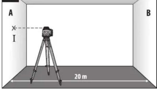
- The procedure has to be carried out in a room at least 20 m long with a stable floor. The measurements should involve X and Y-axis rotation
(in the positive and negative direction for each axis, four measurements in total).
- The level should be mounted horizontally near wall A on a tripod (12) or a stable base (see Fig. C, p. 3). Turn the level on and allow it to auto-level.
- Aim the laser beam point at wall A that is the closest to the device. Mark the centre of the beam on the wall (point I) (see Fig. C, p. 3).
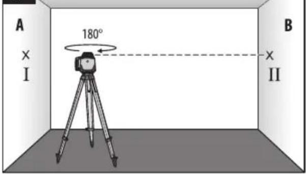
- Rotate the level 180^ around the mounting axis, wait for it to auto-level, and mark the centre of the beam on the opposite wall B (point II) (see Fig. D, p. 3).
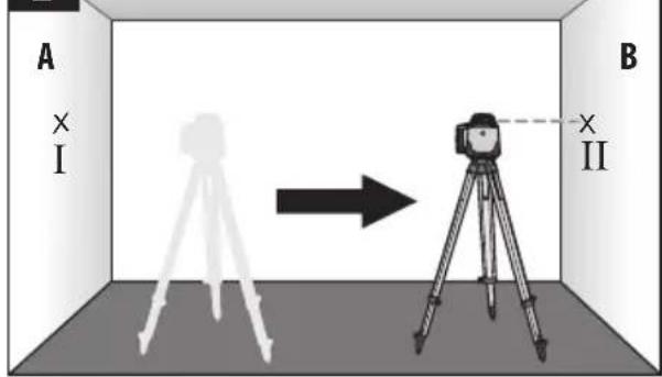
- Move the level (do not rotate it) near wall B and set it to auto-level (see Fig. E, p. 3).
- Change the height of the level on the tripod (12) so that the centre of the beam hits precisely the centre of point II on wall B (see Fig. E, p. 3).
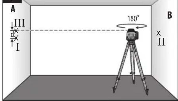
- Rotate the level 180^ around the mounting axis (do not change the height), wait for it to auto-level, and mark the centre of the beam on the opposite wall A (point III) so that it is as much as possible directly above or below point I. The distance (d) between the two points I and II on wall A is the actual level deviation for the measuring axis (see Fig.
F, p. 3). Repeat the measurement for the other axes. To do this, rotate the head (2) 90° before each measurement. The maximum deviation Φ at 20 m is ±1 mm/10 m = ±2 mm. Therefore, the deviation Φ between points I and III must not exceed 2 mm for each measurement. If the maximum deviation is exceeded for any measurement, have the level checked by a service point. To ensure accurate measurements with the level, the verification described above should be performed at least once a month or each time the device is dropped, falls, or is hit during work or transport.
HORIZONTAL AND VERTICAL PLANE:
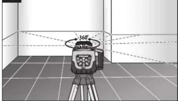
- To draw a horizontal plane, mount the level on a tripod (12) with a 5/8" thread (5). When the laser is switched on, a horizontal plane is drawn by the laser beam. After the device completes auto-levelling, a 360° horizontal plane can be drawn by rotating the head (see Fig. G, p. 3).
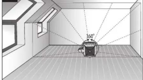
- To draw a vertical plane, set the level on a hard, level surface with the on/off button (14) facing up. When the laser is switched on, a vertical plane is drawn by the laser beam. After the device completes auto-levelling, a 360° vertical plane can be drawn by rotating the head. (see Fig. H, p. 3).
CLEANING, STORAGE AND MAINTENANCE:
NOTE: Turn off the device before cleaning.
- Clean the device only with a dry or slightly moistened cloth. Never use cleaning or scouring cleaners. Carefully remove visible dirt from laser windows ( ) with a soft cloth and a glass cleaner.1
- Clean the device only with a dry or slightly moistened cloth. Never use cleaning or scouring cleaners. Transport and store the level in the original case to protect it from mechanical damage.
- The device is maintenance-free. There are no components in the device that are meant to be repaired by the user. If any errors in operation or damage to the device are observed, please contact an authorised service centre.
MANUFACTURER:
Profix Sp. z o.o.,
ul. Marywilska 34, 03-228 Warsaw, Poland
PICTOGRAMS:
The device features the following warning symbols:

LASER RADIATION.
3RCLASS LASER DEVICE
.AVOID DIRECT EYE EXPOSURE
ATTENTION! Always check the legibility of the plates and warning signs on the laser device.
ENVIRONMENTAL PROTECTION:

The symbol shown indicates a ban on disposal of used equipment together with other waste (subject to a fine). Hazardous components found in electrical and electronic equipment adversely affect the natural environment and human health.
The users should contribute to the recovery and re-use (recycling) of used equipment. A system of collecting used equipment is being created, or is present, in Poland and Europe, under which all sales outlets of the above-mentioned equipment are required to collect used equipment when new equipment is purchased. In addition, there are collection points for the above-mentioned equipment.
AVERTISMENT:


- OSTRZEŻENIE:
- SAFETY RULES:
- USE:
- DELIVERY KIT:
- DEVICE PARTS:
- PREPARATION FOR WORK:
- ■ How to charge the battery
- ■ How to mount the level on the tripod
- OPERATION:
- ■ Laser module auto-levelling
- ■ How to turn the level on
- ■ How to adjust the slope
- ■ Shock safety
- ■ Remote control
- ■ Laser beam detector
- ■ Working with the laser target plate
- ■ Laser enhancing glasses
- ACCURACY OF THE LEVEL:
- ■ Accuracy factors
- ■ Verification of calibration
- HORIZONTAL AND VERTICAL PLANE:
- CLEANING, STORAGE AND MAINTENANCE:
- MANUFACTURER:
- PICTOGRAMS:
- ENVIRONMENTAL PROTECTION:
- AVERTISMENT:
Brand : PROLINE
Model : 15162
Category : Uncategorized