
MM-EE-EEM-MA500 - Measurement Phoenix Contact - Free user manual and instructions
Find the device manual for free MM-EE-EEM-MA500 Phoenix Contact in PDF.


| Product Type | Energy measuring device (EMpro-EE) |
| Model | MM-EE-EEM-MA500 |
| Dimensions (W x H x D) | 96 mm x 96 mm x 73.4 mm |
| Weight | 250 g |
| Power Supply | 85...275 V AC / 120...380 V DC, < 10 VA / 2 W |
| Network Type | Three-phase 4-wire (3P4W) |
| Measurement Functions | Voltage (Ph/Ph, Ph/N), Current, Frequency, Active/Reactive/Apparent Power, Power Factor, Active/Reactive Energy, Max Demand |
| Accuracy (Active Energy) | Class 1 per IEC 62053-21 |
| Accuracy (Reactive Energy) | Class 2 per IEC 62053-23 |
| Current Input | CT primary: 1...9999 A, secondary: 1 A or 5 A, measured: 5 mA...6 A |
| Voltage Input | 50...345 V AC (Ph/N), 87...600 V AC (Ph/Ph) |
| Display | Backlit LCD, automatic scroll |
| Pulse Output | Configurable for kWh or kVArh, pulse constant and duration |
| Operating Temperature | -25°C to +70°C |
| Storage Temperature | -40°C to +70°C |
| Protection Rating | IP51 (front display) |
| Mounting | Panel mount, panel thickness 1.5...3 mm |
| Safety Category | CAT III per IEC 61010-1 |
| Maintenance | Clean with damp cloth; switch off before cleaning; no abrasive agents |
| Spare Parts & Repairability | No user-serviceable parts; contact manufacturer for repairs |
Frequently Asked Questions - MM-EE-EEM-MA500 Phoenix Contact
User questions about MM-EE-EEM-MA500 Phoenix Contact
0 question about this device. Answer the ones you know or ask your own.
Ask a new question about this device
Download the instructions for your Measurement in PDF format for free! Find your manual MM-EE-EEM-MA500 - Phoenix Contact and take your electronic device back in hand. On this page are published all the documents necessary for the use of your device. MM-EE-EEM-MA500 by Phoenix Contact.
USER MANUAL MM-EE-EEM-MA500 Phoenix Contact
EMpro-EE – essential energy measuring devices for front panel installation
User manual
User manual
EMpro-EE – essential energy measuring devices for front panel installation
UM EN MM-EE-EEM-MA500, Revision 00
2023-02-13
This manual is valid for:
Designation
MM-EE-EEM-MA500
Table of contents
1 For your safety....5
1.1 Labeling of warning notes.... 5
1.2 Qualification of users....5
1.3 Field of application of the product.... 5
1.3.1 Intended use 5
1.3.2 Product changes 6
1.4 Safety notes 6
2 Device description....7
2.1 Operating and indication elements .... 7
3 Mounting and installation....9
3.1 Mounting 9
3.2 Network type 10
4 Configuration....11
4.1 Password Entry 11
4.2 CT 11
4.2.1 CT2 12
4.2.2 CT1 12
4.3 Demand 13
4.3.1 Demand method 14
4.3.2 Demand interval time/ Block time (DIT) 14
4.3.3 Sliding time 15
4.4 Time 15
4.4.1 Backlight time 15
4.4.2 Display scroll time 16
4.5 Pulse output....16
4.5.1 Pulse constant 17
4.5.2 Pulse duration 17
4.6 System connect.... 18
4.7 Change password 19
4.8 Automatic display scroll 19
4.9 Reset 20
5 Operation....21
5.1 Start up screens 21
5.2 Buttons and Displays.... 22
5.2.1 Buttons Function 22
5.2.2 Display Mode Screen Sequence 23
6 Technical data 25
A Appendixes....29
A 1 List of figures ...... 29
A 2 List of tables ...... 30
1 For your safety
Read this user manual carefully and keep it for future reference.
1.1 Labeling of warning notes

This symbol indicates hazards that could lead to personal injury.
There are three signal words indicating the severity of a potential injury.
DANGER
Indicates a hazard with a high risk level. If this hazardous situation is not avoided, it will result in death or serious injury.
WARNING
Indicates a hazard with a medium risk level. If this hazardous situation is not avoided, it could result in death or serious injury.
CAUTION
Indicates a hazard with a low risk level. If this hazardous situation is not avoided, it could result in minor or moderate injury.

This symbol together with the NOTE signal word warns the reader of actions that might cause property damage or a malfunction.

Here you will find additional information or detailed sources of information.
1.2 Qualification of users
The use of products described in this user manual is oriented exclusively to:
- Electrically skilled persons or persons instructed by them. The users must be familiar with the relevant safety concepts of automation technology as well as applicable standards and other regulations
– Qualified application programmers and software engineers. The users must be familiar with the relevant safety concepts of automation technology as well as applicable standards and other regulations.
1.3 Field of application of the product
1.3.1 Intended use
The EMpro-EE energy measuring devices described in this user manual are suitable for installation in electrical systems with different voltage levels and performance classes.
Keep in mind that electrical systems pose hazards due to high voltages, high short-circuit currents, electric arcs and/or other hazards.
1.3.2 Product changes
Changes or modifications to hardware and software of the device are not permitted.
Incorrect operation or modifications to the device can endanger your safety or damage the device. Do not repair the device yourself. If the device is defective, please contact Phoenix Contact.
1.4 Safety notes

The "exclamation mark" on the device labeling means that you need to:
Read the installation note in its entirety. Follow the installation note to avoid impairing the intended protection.
- The installation, operation, and maintenance work must be completed by a qualified electrician. Follow the installation instructions as described. When installing and operating the device, the applicable regulations and safety directives (including national safety directives), as well as general technical regulations must be observed.
- Use an appropriate voltage measuring device to ensure that no voltage is present.
- Install the device in accordance with instructions described in the installation notes. Accessing circuits within the device is prohibited.
– Repairs may only be carried out by the manufacturer. - Only clean the device with a suitable damp cloth. Switch the device off before cleaning and do not use abrasive agents or solvents.
- Ensure that all connection terminals are connected correctly to prevent the device from being damaged.
- Observe the maximum permissible voltages (600 V AC phase/phase or 345 V AC phase/neutral conductor).
2 Device description
The energy analyzer MM-EE-EEM-MA500 is an essential panel meter for the power industry and transmission and power distribution system.
This document provides operating, maintenance and installation instructions for the Phoenix Contact MM-EE-EEM-MA500. The unit measures and displays the characteristics of 3p4w, including voltage, frequency, current, power and active and reactive energy, imported or exported, Power factor, Max. Demand etc. Energy is measured in terms of kWh, kVArh and kVAh. Maximum demand current can be measured over preset periods of up to 60 minutes.
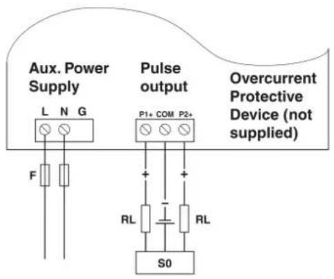
In order to measure energy, the unit requires voltage and current inputs in addition to the supply required to power the product. The requisite current input(s) are obtained via current transformers. The MM-EE-EEM-MA500 can be configured to work with a wide range of CTs, giving the unit a wide range of operation. Built-in interfaces provide Pulse Output for reading energy via pulse collector.
The unit uses plug-in terminals for easy wiring and push-in mechanism for quick installation.
2.1 Operating and indication elements
Figure 2-1 Operating and indication elements
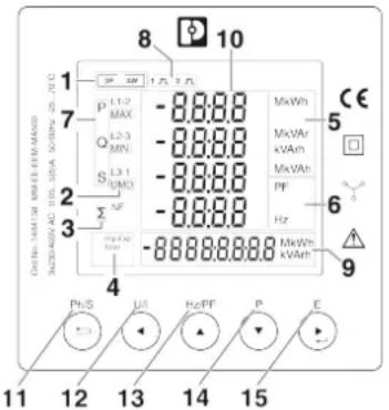
1 System type
2 DMD
3 Σ: Total
4 IMP/EXP: import/Export Value,
Total: Total value
5 Measurement units
6 PF and Hz units
7 P: active power
Q: reactive powerp
S: apparent power
8 Pulse Output
9 Energy: kWh/kVArh units
10 Measurement value
11 Ph/S: Click
– Power, voltage, current of each phase
- Exit from the menu
Press 2S:
– Automatic Scroll display ON / OFF
12 12U/I: Click
– Voltage and current.(3p4w), phase sequence
- Left key
13 Hz/PF: Click
– Power factor, frequency, Max. Demand.
- Up key
14 P: Click
– Display active power, reactive power and apparent power
- Down key
Press 2S:
- CT ratio setting, running, software version and full screen
15 E: Click
– Display total / import / export active or reactive energy
- Right key
Press 2S:
- Set-up mode entry
- Confirmation
3 Mounting and installation
3.1 Mounting
You can install the device in a front panel or control cabinet door.
Figure 3-1 Mounting
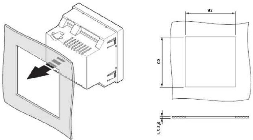
The unit may be mounted in a panel of any thickness up to a maximum of 3 mm.
Leave enough space behind the instrument to allow for bends in the connection cables.
The unit is intended for use in a reasonably stable ambient temperature within the range - 25°C to +70°C. Do not mount the unit where there is excessive vibration or in excessive direct sunlight.
Figure 3-2 Mounting introduction
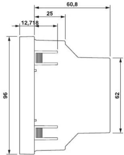
3.2 Network type
Figure 3-3 3P4W 3CT
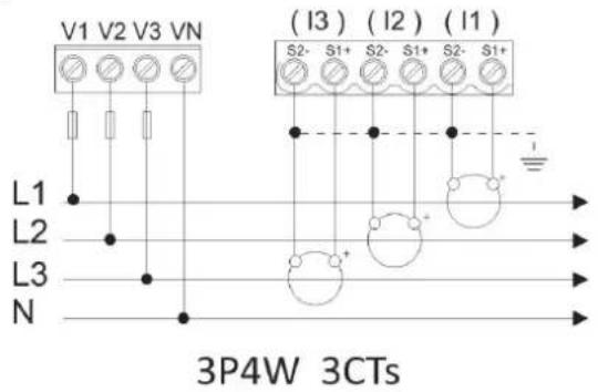
Figure 3-4 Pulse output installation
4 Configuration
4.1 Password Entry
PASS
1000
Setting-up mode is password protected, so you must enter the correct password.
Default password: 1000

By firmly press the button for 2 s, the password screen appears. Use
and, to set the password. If an incorrect password is entered, the display shows ERR.
4.2 CT
SET
[1]
CT set up menu:

From the main Set-up menu, use and to select the CT option.
4.2.1 CT2
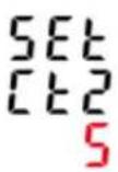 A A | Set secondary current input the meterOptions: 5 A or 1 ADefault CT2: 5 ALong press to enter th routine. Press for 2s, the CT2 setting will flash. Use to choose CT2 with 5 A or 1 A. |
 | Example shows:Set CT2 1 AAnd long press to confirmation. |
4.2.2 CT1
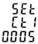 A A | Set primary current input the meterOptions: 1 ... 9999Default CT1: 5 A   Use and to enter the CT1 routine. Press for 2s, the CT1 Use and to enter the CT1 routine. Press for 2s, the CT1  setting will flash. Use and to choose CT1 with 1...9999. setting will flash. Use and to choose CT1 with 1...9999. |
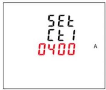 | Example shows:Set CT1 400A  And long press for confirmation. Press to return the CT set up menu. And long press for confirmation. Press to return the CT set up menu. |
4.3 Demand
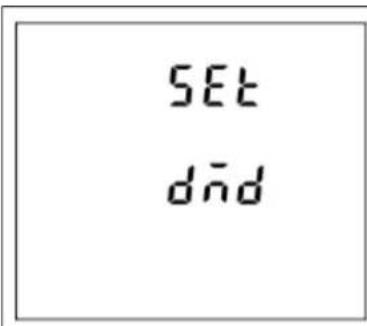
This sets the period in minutes over which the current and power readings are integrated for maximum demand measurement. The options are: OFF, 5, 8, 10, 15,30, 60 minutes.

The unit provides block interval demand calculation. In this method, you select a 'block' of time that power meter uses for the demand calculation. You choose how the power meter handles that block of time (interval). Two different modes are optional.
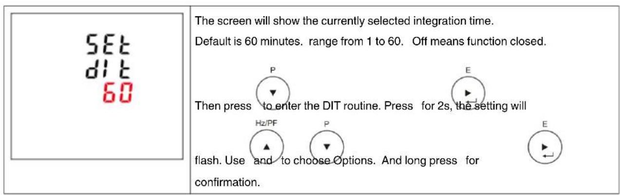
Slide Block: Select a demand interval time (DIT) from 1 to 60 minutes (in 1 minute increments). Set the calculation update time from 1 to 59 minutes. The power meter displays the demand value for the last completed interval.
Figure 4-1 Timed sliding Block
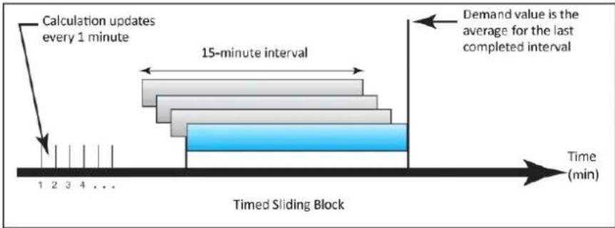
flowchart
graph LR
    A["Calculation updates every 1 minute"] --> B["15-minute interval"]
    B --> C["Demand value is the average for the last completed interval"]
    C --> D["Time (min)"]
    style A fill:#f9f,stroke:#333
    style B fill:#ccf,stroke:#333
    style C fill:#cfc,stroke:#333
    style D fill:#fcc,stroke:#333
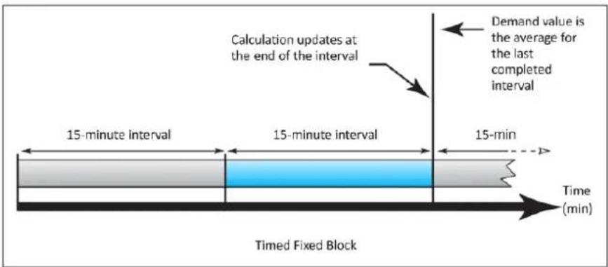
Fixed Block: Select an interval from 1 to 60 minutes (in 1 minute increments). The power meter calculates an updates the demand at the end of each interval.
Figure 4-2 Timed Fixed Block
4.3.1 Demand method
| SET dnd ntHd SLId | The screen shows the Demand calculation method: Slid Options: Fix and Slid Hz/PF P Use and to enter Demand calculation method. |
| SET dnd ntHd FI= | Long press to enter the routine. The setting will flash. Use and P to choose Options. And long press for confirmation. |
4.3.2 Demand interval time/ Block time (DIT)
4.3.3 Sliding time
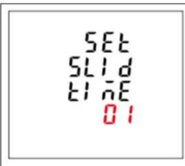
The screen will show the Sliding time for the sliding mode.
The sliding time shall be set not bigger than the DIT.
4.4 Time
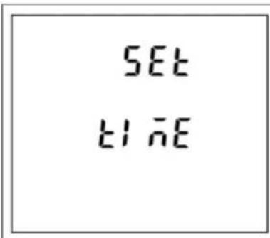
Time set up menu:
This option sets the backlight lasting time and display scroll time.
From the Set-up menu, use and to select the Time option.
4.4.1 Backlight time
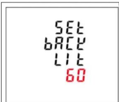
The meter provides a function to set the backlit lasting time.
Options: ON/OFF/5/10/30/60/120 minutes. Default: 60
If it is seated as 5, the backlit will be off in 5 minutes.
Note: if it is set as ON, the backlit will always be on.


Long press to enter the Backlit time routine. Press for 2s, the setting

will flash. Use and to choose Options. And long press for confirmation.
4.4.2 Display scroll time
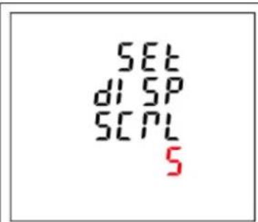
The meter provides a function to set the Display scroll time.
Options: 1 ... 255s
Default: 5
If it is seated as 5, the display will scroll every 5s.


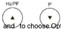
Use and to select Display scroll time option. Press for 2s,

Hz/PF P the setting will flash. Use and to choose Options. And Long press


for confirmation. Press to return to the time set up menu.
4.5 Pulse output
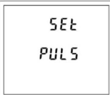
The meter provides a function to configure the Pulse Output. The output can be set to provide a pulse for a defined amount of energy active or reactive.

Long press to enter the Pulse routine.
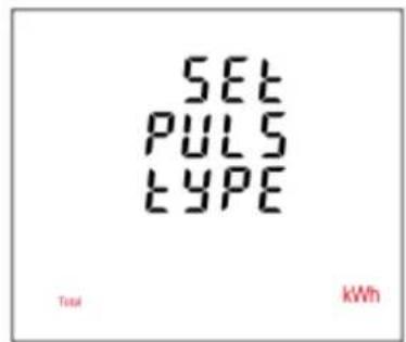
Options: Total kWh and total kVArh. Default: Total kWh


Press for 2s, the setting will flash. Use and to choose

Options. And long press for confirmation.
4.5.1 Pulse constant
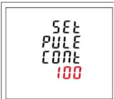
The meter provides a function to set the energy represented by each pulse. Pulse constant can be set to 0.001/0.01/0.1/1/10/100 imp/kWh or kVArh.

Long press to enter the Pulse constant routine. Press for 2s, the

Hz/PF P setting will flash. Use and to choose Options. And long press

for confirmation.
4.5.2 Pulse duration
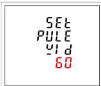
The meter provides a function to set the pulse width.
Options: 200/100/60ms
Default: 200ms

Long press to enter the Pulse duration routine. Press for 2s, the

setting will flash. Use and to choose Options. And long press

for confirmation.
4.6 System connect
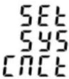 | This unit provides a function with Reverse connected current inputs correction setting. Use and to select the correction option. Use and to select the correction option. |
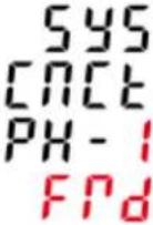 | Options: Frd (forward) and rEv (reverse)The default is FRD (forward)  Long press to enter the Phase 1 correction. Press for 2s, the setting will flash. Use to cl Options. And long press for confirmation. Long press to enter the Phase 1 correction. Press for 2s, the setting will flash. Use to cl Options. And long press for confirmation. |
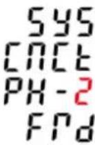 |   Press other Phase 2 correction. Press for 2s, the setting will flash. Press other Phase 2 correction. Press for 2s, the setting will flash.  Use and to cho options. And long press for confirmation. Use and to cho options. And long press for confirmation. |
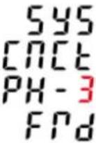 |   Press other Phase 3 correction. Press for 2s, the setting will flash. Press other Phase 3 correction. Press for 2s, the setting will flash.  Use and to choose options. And long press for confirmation. Press to return the System set up menu. Use and to choose options. And long press for confirmation. Press to return the System set up menu. |
4.7 Change password
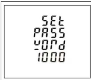
This unit provides a function with password setting.
Default: 1000
Options:0000 ... 9999
Use and to select the change password option.
Press

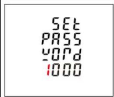
for 2s, the setting will flash. Use and ,


choose Options. And long press for confirmation.

4.8 Automatic display scroll
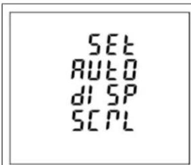
This unit provides a function with automatic display scroll setting.
Options: on and off
There are two ways:


1 Use and to select the automatic display scroll option. Press

for 2s, the setting will flash. Use

"On" or "Off". And long press for confirmation.
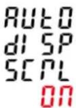 | 2 Escape the Setting menu. Long press for 2 s For example, the screen shows the currently selected Automatic Scroll display ON. |
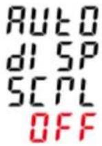 | Long press  , then the screen shows the currently selected Automatic Scroll display OFF. , then the screen shows the currently selected Automatic Scroll display OFF. |
4.9 Reset
 | This unit provides a function to reset the demand. Long press to enter the Demand Reset routine. Long press to enter the Demand Reset routine. |
 |  Press torzs, the setting will flash. And long press for conmmation. Press torzs, the setting will flash. And long press for conmmation. |
5 Operation
5.1 Start up screens
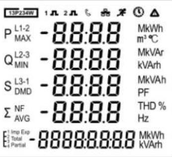 | The first screen lights all segments and can be used as a display check. |
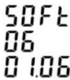  | The second screen indicates the software version of the unit.(The left picture is just for reference) |
 | The unit performs a self - test and the screen indicates if the test is passed. |
After a short delay, the default measurement screen appears.
5.2 Buttons and Displays
5.2.1 Buttons Function
| Buttons Click Press 2S | ||
Ph/S | - Displays power, voltage, current and energy information of each phase- Exit from the menu | - Automatic Scroll display ON / OFF |
U/I | - Display voltage and current and phase sequence information- Left side move | |
Hz/PF | - Display power factor, frequency, Max. Demand.- Up page or add value | |
P | - Display active power, reactive power and apparent power information- Down page or reduce value | - CT ratio setting- Running hour- Software version- Full Screen checking |
E | - Display total / import / export active or reactive energy information- Right side move | - Set-up mode entry- Confirmation |
5.2.2 Display Mode Screen Sequence
| Click 3 Phase 4 Wire | ||
Ph/S | 1 Phase 1 – Power | VoltageCurrentkWh |
| 2 Phase 2 – Power | VoltageCurrentkWh | |
| 3 Phase 3 – Power | VoltageCurrentkWh | |
| 4 Phase 1 – Power | VoltageCurrentkVArh | |
| 5 Phase 2 – Power | VoltageCurrentkVArh | |
| 6 Phase 3 – Power | VoltageCurrentkVArh | |
U/I | 1 Voltage L1-N | Voltage L2-NVoltage L3-N |
| 2 Voltage L1-L2 | Voltage L2-L3Voltage L3-L1 | |
| 3 Current L1 | Current L2Current L3Current Neutral | |
| 4 Phase Sequence | ||
Hz/PF | 1 Total Power Factor | Frequency |
| 2 PF L1 | PF L2PF L3 | |
| 3 Max. DMD of Current L1Max. DMD of Current L2Max. DMD of Current L3 | ||
| 4 Max. DMD of kW | Max. DMD of kVArMax. DMD of kVA | |
P | 1 Active Power L1 | Active Power L2Active Power L3 |
| 2 Reactive Power L1 | Reactive Power L2Reactive Power L3 | |
| 3 Apparent Power L1 | Apparent Power L2Apparent Power L3 | |
| 4 Total Active Power | Total Reactive PowerTotal Apparent Power | |
E | 1 Total kWh | |
| 2 Total kVArh | ||
| 3 Import kWh | ||
| 4 Export kWh | ||
| 5 Import kVArh | ||
| 6 Export KVArh | ||
6 Technical data
Table 6-1
| Electrical characteristics | |||
| Type of measurement RMS including harmonics | on three phase AC system(3P+N)128 samples per cycle | ||
| Measurement accuracy | Power IEC 61557-12 Class 1 | ||
| Active Energy | IEC 62053-21 Class 1 | ||
| Reactive Energy | IEC 62053-23 Class 2 | ||
| Current ± 0.5% | |||
| Voltage ± 0.5% | |||
| Power Factor ± 0.01 | |||
| Data Update Rate 1 s nominal | |||
| Input-Voltage Un | 230 V Ph/N | ||
| Measured Voltage with Over-range and Crest Factor | 87 ... 600 V AC(Ph/Ph)50 ... 345 V AC(Ph/N) | ||
| Permanent Overload | 600 V Ph/Ph345 V Ph/N | ||
| Impedance | <1 MΩ | ||
| Frequency Range | 45 ... 65 Hz | ||
| Input- Current | CT Ratings | Primary | 1 ... 9999 A |
| Secondary | 1 A / 5 A | ||
| Measured current with Over-range and Crest Factor | 5 mA ... 6 A | ||
| Withstand | Continuous 6A120 A for 0.5 s | ||
| Impedance | <1 MΩ | ||
| Frequency Range | 45 ... 65 Hz | ||
| Burden | <0.036 VA at 6 A | ||
| Auxiliary Power Supply | Operating Range | 85 ... 275 V AC / 120 ... 380 V DC | |
| Power Consumption <10 VA/2 W | |||
| Frequency | 45 ... 65 Hz | ||
| Mechanical Characteristics | |||
| Weight | 250g | ||
| IP Degree of Protection (IEC 60529) | IP51 front display | ||
| Dimensions (width/height/depth) | 96 mm x 96 mm x 73.4 mm | ||
| Mounting Position | Vertical | ||
| Panel Thickness | 1.5 ... 3 mm | ||
| Material of meter case Self-extinguishing UL 94 V-0 | |||
| Mechanical environment | M1 | ||
| Environmental Characteristics | |
| Operating Temperature -25 ... 70°C | |
| Storage Temperature -40 ... 70°C | |
| Humidity Rating <95% RH at 50°C (non-condensing) | |
| Pollution Degree 2 | |
| Altitude | ≤2000 m |
| Vibration 10 ... 50 Hz, IEC 60068-2-6 | |
| Electromagnetic Compatibility | |
| Electrostatic Discharge IEC 61000-4-2 | |
| Immunity to Radiated Fields IEC 61000-4-3 | |
| Immunity to Fast Transients IEC 61000-4-4 | |
| Immunity to Impulse Waves IEC 61000-4-5 | |
| Conducted Immunity IEC 61000-4-6 | |
| Immunity to Magnetic Fields IEC 61000-4-8 | |
| Immunity to Voltage Dips IEC 61000-4-11 | |
| Radiated Emissions EN55022 Class B | |
| Conducted Emissions EN55022 Class B | |
| Harmonics IEC 61000-3-2 | |
| Safety | |
| Measurement Category | Per IEC61010-1CAT III |
| Current Inputs | Require external Current Transformer for Insulation |
| Over voltage Category | CAT III |
| Dielectric Withstand | As per IEC 61010-1 Double Insulated front panel display |
| Protective Class | II |
Table 6-2
| Features | Description |
| MM-EE-EEM-MA550 | |
| Instantaneous Measurements | |
| Current | ● |
| Voltage Ph/Ph | ● |
| Ph/N | ● |
| Frequency | ● |
| Active power | ● |
| Reactive power | ● |
| Apparent power | ● |
| Power factor | ● |
| Energy Values | |
| Active energy | ● |
| Reactive energy | ● |
| Maximum Demand Values | |
| Maximum current ● | |
| Maximum total active power ● | |
| Maximum total reactive power ● | |
| Maximum total apparent power ● | |
| Network | |
| Three phase 4 wire ● | |
| CT programmable ● | |
| Communications | |
| Pulse output ● | |
| Accuracy | |
| Active energy Cl. 1 | |
| Reactive energy Cl. 2 | |
| Current 0.5% | |
| Voltage 0.5% | |
| Power 1% | |
| Hz 0.2% | |
| Number of measurement points per circle 128 | |
| Auxiliary power supply | ● |
Note: ● = included
A Appendixes
A 1 List of figures
Section 2
Figure 2-1: Operating and indication elements ....7
Section 3
Figure 3-1: Mounting 9
Figure 3-2: Mounting introduction ...... 9
Figure 3-3: 3P4W 3CT 10
Figure 3-4: Pulse output installation .... 10
Section 4
Figure 4-1: Timed sliding BlockTimed Sliding Block 13
Figure 4-2: Timed Fixed Block ....13
A 2 List of tables
Table 6-1: 25
Table 6-2: 26
Please observe the following notes
General terms and conditions of use for technical documentation
Phoenix Contact reserves the right to alter, correct, and/or improve the technical documentation and the products described in the technical documentation at its own discretion and without giving prior notice, insofar as this is reasonable for the user. The same applies to any technical changes that serve the purpose of technical progress.
The receipt of technical documentation (in particular user documentation) does not constitute any further duty on the part of Phoenix Contact to furnish information on modifications to products and/or technical documentation. You are responsible to verify the suitability and intended use of the products in your specific application, in particular with regard to observing the applicable standards and regulations. All information made available in the technical data is supplied without any accompanying guarantee, whether expressly mentioned, implied or tacitly assumed.
In general, the provisions of the current standard Terms and Conditions of Phoenix Contact apply exclusively, in particular as concerns any warranty liability.
This manual, including all illustrations contained herein, is copyright protected. Any changes to the contents or the publication of extracts of this document is prohibited.
Phoenix Contact reserves the right to register its own intellectual property rights for the product identifications of Phoenix Contact products that are used here. Registration of such intellectual property rights by third parties is prohibited.
Other product identifications may be afforded legal protection, even where they may not be indicated as such.
How to contact us
Internet
Up-to-date information on Phoenix Contact products and our Terms and Conditions can be found on the Internet at: phoenixcontact.com
Make sure you always use the latest documentation. It can be downloaded at: phoenixcontact.net/products
Subsidiaries
If there are any problems that cannot be solved using the documentation, please contact your Phoenix Contact subsidiary. Subsidiary contact information is available at phoenixcontact.com.
Published by Phoenix Contact GmbH & Co. KG
Phoenix Contact Asia-Pacific (Nanjing) Co., Ltd. No.36 Phoenix Rd, Jiangning Development Zone 211100 Nanjing CHINA
Should you have any suggestions or recommendations for improvement of the contents and layout of our manuals, please send your comments to: tecdoc@phoenixcontact.com
Phoenix Contact GmbH & Co. KG
Flachsmarktstraße 8
32825 Blomberg, Germany
Phone: +49 5235 3-00
Fax: +49 5235 3-41200
Email: info@phoenixcontact.com
phoenixcontact.com
- EMpro-EE – essential energy measuring devices for front panel installation
- User manual
- Table of contents
- For your safety....5
- Device description....7
- Mounting and installation....9
- Configuration....11
- Operation....21
- For your safety
- Labeling of warning notes
- DANGER
- WARNING
- CAUTION
- Qualification of users
- Field of application of the product
- Intended use
- Product changes
- Safety notes
- Device description
- Operating and indication elements
- Mounting and installation
- Mounting
- Network type
- Configuration
- Password Entry
- CT
- CT2
- CT1
- Demand
- Demand method
- Demand interval time/ Block time (DIT)
- Sliding time
- Time
- Backlight time
- Display scroll time
- Pulse output
- Pulse constant
- Pulse duration
- System connect
- Change password
- Automatic display scroll
- Reset
- Operation
- Start up screens
- Buttons and Displays
- Buttons Function
- Technical data
- A Appendixes
- A 1 List of figures
- Section 2
- Section 3
- Section 4
- A 2 List of tables
- Please observe the following notes
- General terms and conditions of use for technical documentation
- How to contact us
- Internet
- Subsidiaries
- Published by Phoenix Contact GmbH & Co. KG
Brand : Phoenix Contact
Model : MM-EE-EEM-MA500
Category : Measurement