
MM-EE-EEM-MA550 - Measurement Phoenix Contact - Free user manual and instructions
Find the device manual for free MM-EE-EEM-MA550 Phoenix Contact in PDF.


| Product Type | Energy Measurement Module |
| Model | MM-EE-EEM-MA550 |
| Brand | Phoenix Contact |
| Dimensions (H x W x D) | 90 mm x 36 mm x 70 mm |
| Weight | Approximately 100 g |
| Power Supply | 24 V DC |
| Power Consumption | 5 W |
| Measurement Accuracy | Class 0.5 according to IEC 61557-12 |
| Measurement Categories | Voltage, Current, Power, Energy |
| Communication Interface | Modbus RTU (RS-485) |
| Mounting Type | DIN Rail (EN 60715) |
| Operating Temperature | -25°C to +55°C |
| Protection Rating | IP20 (enclosure) |
| Safety Standards | Overvoltage category II, pollution degree 2 |
| Maintenance | Clean with a dry, lint-free cloth. No internal parts serviceable. |
| Spare Parts | None; device is not field-repairable. Replace entire module if faulty. |
| General Information | Part of the Phoenix Contact ME-Series for energy data acquisition. |
| Viewing Window | Optional display with backlit LCD for local reading. |
| Software Compatibility | Compatible with Phoenix Contact's energy management software (e.g., EEM Suite). |
| Warranty | 1 year from date of purchase (standard). |
Frequently Asked Questions - MM-EE-EEM-MA550 Phoenix Contact
User questions about MM-EE-EEM-MA550 Phoenix Contact
0 question about this device. Answer the ones you know or ask your own.
Ask a new question about this device
Download the instructions for your Measurement in PDF format for free! Find your manual MM-EE-EEM-MA550 - Phoenix Contact and take your electronic device back in hand. On this page are published all the documents necessary for the use of your device. MM-EE-EEM-MA550 by Phoenix Contact.
USER MANUAL MM-EE-EEM-MA550 Phoenix Contact
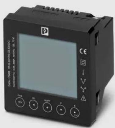
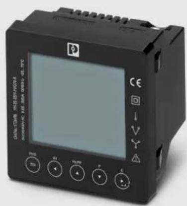
EE EMpro - energy measuring devices for front panel installation
User manual
User manual
EE EMpro - energy measuring devices for front panel installation
UM EN EE EMpro front panel, Revision 01
2024-10-16
This user manual is valid for:
Designation Item No.
MM-EE-EEM-MA550 1475401
MM-EE-EEM-MA550-4DI/2DO 1726498
MM-EE-EEM-MA570-R 1726496
MM-EE-EEM-MA570-R-4DI/2DO 1726500
Table of contents
1 For your safety ....5
1.1 Identification of warning notes....5
1.2 Qualification of users ....5
1.3 Field of application of the product....5
1.3.1 Intended use 5
1.3.2 Product changes ....5
1.4 Safety notes....6
2 Devices description....7
2.1 Product overview....7
2.2 Operating and indicating elements....8
3 Mounting and installation....9
3.1 Mounting....9
3.2 Connection assignment.... 10
3.3 Grid types 11
4 Operation.... 13
4.1 Start mode.... 13
5 Configuration.... 15
5.1 Opening setting mode 15
5.2 Communication 15
5.2.1 Address setting 16
5.2.2 Baud rate 16
5.2.3 Parity 17
5.2.4 Stop bit 18
5.3 CT 18
5.3.1 CT2 19
5.3.2 CT1 19
5.4 PT 20
5.4.1 PT2 21
5.4.2 PT1 21
5.5 Demand 22
5.5.1 Demand method 23
5.5.2 Demand interval time/ Block time (DIT) 24
5.5.3 Sliding time 24
5.6 Time 25
5.6.1 Backlight lasting time 25
5.6.2 Display scroll time 26
5.6.3 System RTC 26
5.6.4 Tariff Time 28
5.7 System 28
5.7.1 System type 29
5.7.2 System connect 29
5.7.3 Password 30
5.7.4 Auto display scroll 30
5.8 Digital inputs (DI) 31
5.9 Digital outputs (DO) 33
5.10 Ethernet communication.... 37
5.11 SOE information 39
5.12 Reset....40
6 Communication....43
6.1 Modbus RTU (Default settings) 43
6.2 Ethernet (Default settings).... 43
7 Technical data....44
8 Modbus register Map 46
8.1 Measuring values 46
8.2 Device information and configuration.... 54
8.3 Read input status of Digital inputs....68
8.4 Read coil status of Digital inputs 68
8.5 Force Single Coil....69
A Appendixes 71
A 1 List of figures....71
A 2 List of tables 73
1 For your safety
Read this manual carefully and keep it for future reference.
1.1 Identification of warning notes

This symbol indicates hazards that could lead to personal injury.
There are three signal words indicating the severity of a potential injury.
DANGER
Indicates a hazard with a high risk level. If this hazardous situation is not avoided, it will result in death or serious injury.
WARNING
Indicates a hazard with a medium risk level. If this hazardous situation is not avoided, it could result in death or serious injury.
CAUTION
Indicates a hazard with a low risk level. If this hazardous situation is not avoided, it could result in minor or moderate injury.

This symbol together with the NOTE signal word warns the reader of actions that might cause property damage or a malfunction.

Here you will find additional information or detailed sources of information.
1.2 Qualification of users
The use of products described in this manual is oriented exclusively to:
- Electrically skilled persons or persons instructed by them. The users must be familiar with the relevant safety concepts of automation technology as well as applicable standards and other regulations.
– Qualified application programmers and software engineers. The users must be familiar with the relevant safety concepts of automation technology as well as applicable standards and other regulations.
1.3 Field of application of the product
1.3.1 Intended use
The EMpro-EE energy measuring devices described in this user manual are suitable for installation in electrical systems with different voltage levels and performance classes.
Keep in mind that electrical systems pose hazards due to high voltages, high short-circuit currents, electric arcs and/or other hazards.
1.3.2 Product changes
Modifications to hardware and firmware of the device are not permitted.
Incorrect operation or modifications to the device can endanger your safety or damage the device. Do not repair the device yourself. If the device is defective, please contact Phoenix Contact.
1.4 Safety notes

The "exclamation mark" on the device labeling means that you need to: Read the installation note in its entirety. Follow the installation note to avoid impairing the intended protection.
-- The installation, operation, and maintenance work must be completed by a qualified
– electrician. Follow the installation instructions as described. When installing and operating the device, the applicable regulations and safety directives (including national safety directives), as well as general technical regulations must be observed.
-- Use an appropriate voltage measuring device to ensure that no voltage is present.
-- Install the device in accordance with instructions described in the installation notes.
- Accessing circuits within the device is prohibited.
-- Repairs may only be carried out by the manufacturer.
- Only clean the device with a suitable damp cloth. Switch the device off before cleaning and do not use abrasive agents or solvents.
-- Ensure that all connection terminals are connected correctly to prevent the device
– from being damaged.
-- Observe the maximum permissible voltages (600 V AC phase/phase or 345 V AC
- phase/neutral conductor).
2 Devices description
MM-EE-EEM-MA5xx series multi-function energy meters with external transformer access can accurately measure and display various electrical parameters in single-phase two-wire, three-phase three-wire and three-phase four-wire power grids.
The device is front panel mounted, supports Modbus RTU and Modbus TCP communications, optional digital inputs and digital outputs for external signal counting and control, and SOE event alarm recording, making it ideal for energy consumption monitoring.
2.1 Product overview
Table 2-1 Product overview
| Description Front panel devices | ||
| Digital inputs/outputs Without DI/DO With 4DI/2D | ||
| Modbus RTU MM-EE-EEM-MA550 | 1475401 | MM-EE-EEM-MA550-4DI/2DO1726498 |
| Modbus RTU + Modbus TCP MM-EE-EE | M-MA570-R1726496 | MM-EE-EEM-MA570-R-4DI/2DO1726500 |
2.2 Operating and indicating elements
Figure 2-1 Operating and indicating example
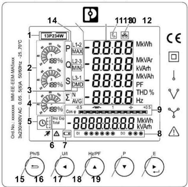
1 Power grid type
2 Sector-shaped power indicator
3 Demand
4 Aggregate value Mean value
5 Rate Status Indicator
6 Positive/inverse value
Total value
7 Low battery backup indication
8 DI / DO status indication
9 Power factor indicator bar
10 Ethernet communication status indication
11 Modbus RTU Communication status indication
12 Parameter value
13 Minimum/maximum value
14 P: active power
Q: reactive power
S: apparent power
15 Ph/S, ESC key
16 U/I, Left key
17 Hz/PF, Up key
18 P, Down key
19 E, Right/Enter key
3 Mounting and installation
3.1 Mounting
You can install the device in a front panel or control cabinet door.
Figure 3-1 Operating and indicating example
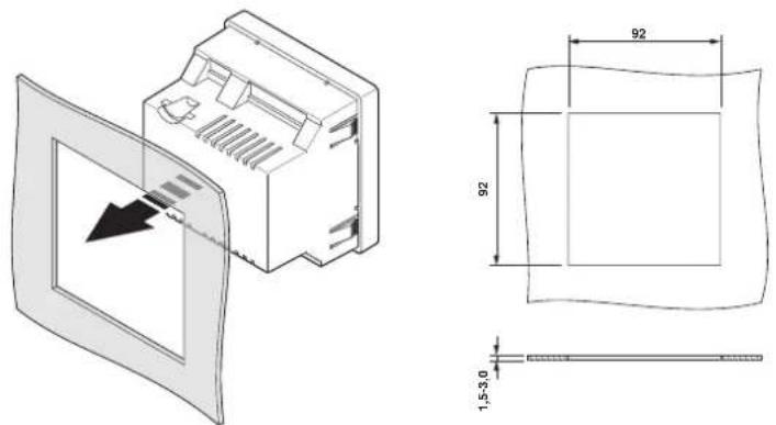
The instrument is pushed into the panel slot (size 92x92 mm) and can be mounted on panels with a thickness of 1 mm to 5 mm, leaving enough space behind the instrument to allow the connection cables to be bent.
The unit can be used stably in ambient temperatures from -25^ to +70^ .
Do not install the unit in areas with excessive vibration or in direct sunlight.
3.2 Connection assignment
Figure 3-2 Pin assignment example
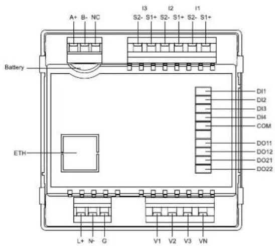
A+, B-, NC RS-485(+,-, NC)
I1, I2, I3 Current measuring input
DI1, DI2, DI3, DI4, COM Digital inputs
V1, V2, V3, VN
Voltage measuring input
L, N, G Power supply
DO11, DO12, DO21, DO22 Digital outputs
Ethernet Ethernet interface (RJ45)
Battery CR 2032

When you replace the battery, make sure the meter's voltage input must be disconnected.
3.3 Grid types
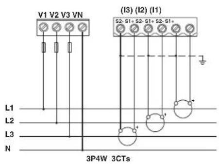
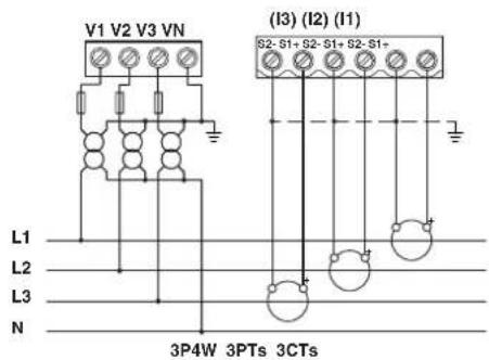
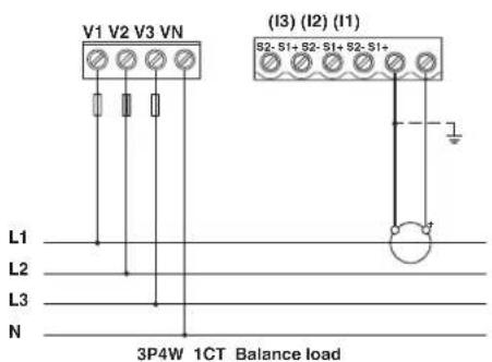
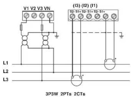
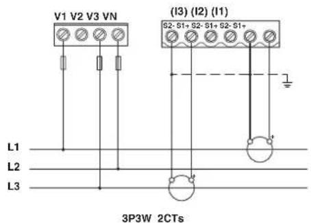
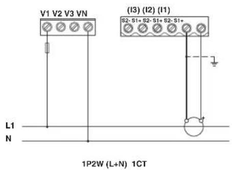
The devices support wiring in many different situations in 1-phase 2-wire,
3-phase 3-wire, or 3-phase 4-wire networks.
- 3P4W3CTs
- 3P4W 3PTs 3CTs
- 3P4W1CT
• 3P3W 2PT 2CTs
- 3P3W 2CTs
• 1P2W 1CT
4 Operation
4.1 Start mode
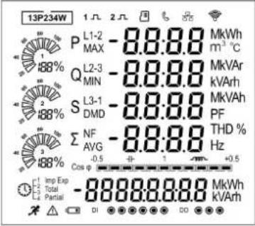 | All display segments and can be used as a display check. |
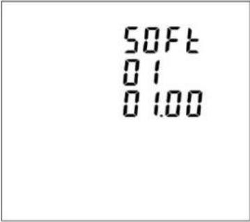 | The second screen indicates the software version installed in the unit. Note: the actual display might be different with the left on here. |
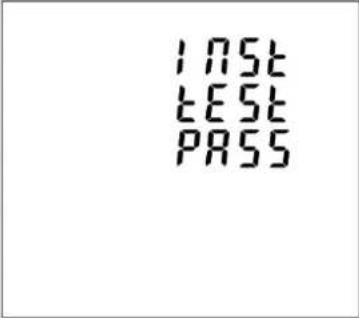 | The interface performs a self-test and indicates the result if the test passes. |
After a short delay, the default measurement screen appears.
| Keys Press | Long Press (2s) | |
Ph/S | - Displays power, voltage, current and energy information of each phase- Exit from the menu | - Automatic Scroll display ON / OFF |
U/I | - Display Voltage and current information of the selected system type. (3p4w, 3p3w and 1p2w)- Phase sequence- Left side move | - Individual Harmonic Distortion of Voltage up to 63rd |
Hz/PF | - Display power factor, frequency, Max. Demand.- Max. and Min. of current and voltage- Up page or add value | - Individual Harmonic Distortion of Current up to 63rd |
P | - Display active power, reactive power and apparent power information of the selected grid type.- Down page or reduce value | - Running hour- Full Screen checking- Modbus (RTU/TCP) setting information- Multi-Tariff information |
E | - Display total / import / export active or reactive energy information of the selected grid type.- Right side move | - Enter setting mode- Confirmation |
5 Configuration
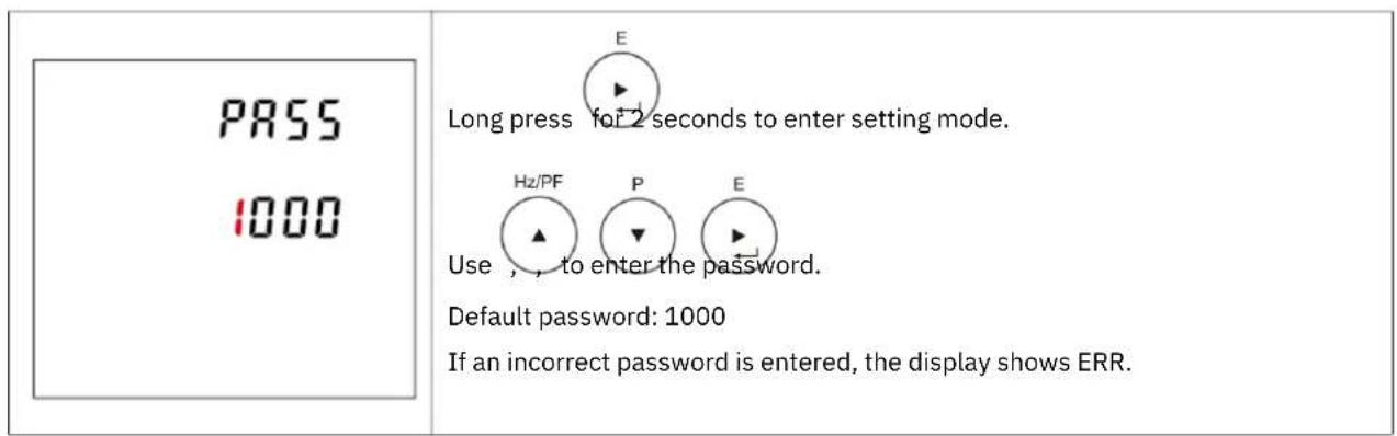
5.1 Opening setting mode
5.2 Communication
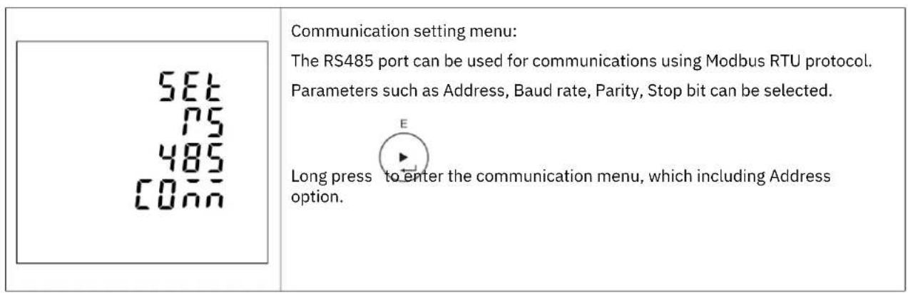
5.2.1 Address setting
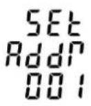 | 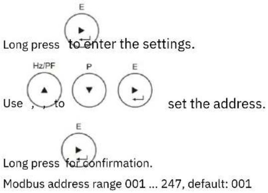 |
5.2.2 Baud rate
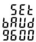 |  From the Communication menu, use Baud rate options. From the Communication menu, use Baud rate options. Long press to enter the setting of Baud Rate. Long press to enter the setting of Baud Rate. Use ud Rate.Baud rate options: 2400, 4800, 9600, 19200, 38400 bps.Default: 9600 bps Use ud Rate.Baud rate options: 2400, 4800, 9600, 19200, 38400 bps.Default: 9600 bps |
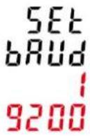 | Example shows:SET Baud rate: 19200 bps. Long press for confirmation. Long press for confirmation. |
5.2.3 Parity
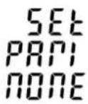 | From the Communication menu, use and to select the Parity options. Long press to enter the setting of Parity. Long press to enter the setting of Parity.  Use and to choose Parity.Parity Options: NONE, EVEN, Odd.Default: NONE Use and to choose Parity.Parity Options: NONE, EVEN, Odd.Default: NONE |
 | Example shows:SET Parity: EVEN*Parity can only be changed to EVEN when the Stop Bit is set to 1. Long press confirmation. Long press confirmation. Press to return the communication setting menu. Press to return the communication setting menu. |
 | Example shows:SET Parity: Odd*Parity can only be changed to Oddwhen the Stop Bit is set to 1. Long press for confirmation. Long press for confirmation. Press to return the communication setting menu. Press to return the communication setting menu. |
5.2.4 Stop bit
| [GTG7] | From the Communication menu, use and to select the Stop Bit options. Long press to enter the setting of Stop Bit. Long press to enter the setting of Stop Bit.  Use stop bit options: 1 or 2. Default: 1Note: If parity is set to Odd or EVEN, Stop Bit will be set to 1 and cannot be changed. Use stop bit options: 1 or 2. Default: 1Note: If parity is set to Odd or EVEN, Stop Bit will be set to 1 and cannot be changed. | |
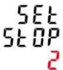 | Example shows:SET Stop bit 2 Long press confirmation. Long press confirmation. Press to return the Communication setting menu. Press to return the Communication setting menu. |
5.3 CT
  | CT setting menu:  From the main setting menu, use and to select the CT option. From the main setting menu, use and to select the CT option. |
5.3.1 CT2
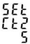 A A | Set secondary current input the meterOptions: 5 A or 1 A, default CT2: 5 A Long press to enter the CT2 routine. Long press to enter the CT2 routine. Press ____, the CT2 setting will flash. Press ____, the CT2 setting will flash.  Use ____ p choose CT2 with 5 A or 1 A. Use ____ p choose CT2 with 5 A or 1 A. |
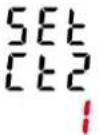 A A | Example shows:SET CT2 1 A Long press to confirmation. Long press to confirmation. |
5.3.2 CT1
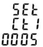 A A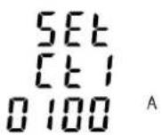 | Set primary current input the meterOptions: 1 ... 9999 A, default CT1: 5 A  Use to enter CT1 routine. Use to enter CT1 routine. Press , the CT1 setting will flash. Press , the CT1 setting will flash.  Use o ch 1 with 1...9999 A.Example shows:SET CT1 100 A Use o ch 1 with 1...9999 A.Example shows:SET CT1 100 A Long press for confirmation.Ph/S Long press for confirmation.Ph/S Press to return the CT setting menu. Press to return the CT setting menu. |
5.4 PT
 Pt Pt | PT setting menu:The PT option sets the primary voltage and secondary voltage of the voltage transformer (PT) that give into the meter.For example: if the PT connect to the meter is 10000/100V, primary voltage is 10000V, secondary voltage is 100V. Long press to enter the PT2 routine. Long press to enter the PT2 routine. Press for 2s, the PT2 setting will flash. Press for 2s, the PT2 setting will flash.   Use , _ , _ , _ , _ , _ , _ , _ , _ , _ Use , _ , _ , _ , _ , _ , _ , _ , _ , _ |
5.4.1 PT2
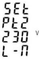 | Set secondary voltage input the meter.Range: 50 ... 600VDefault: 230V Long press for confirmation. Long press for confirmation. |
5.4.2 PT1
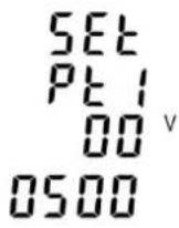 | Set primary voltage input the meter.Range: 50 ... 600000V, default: 230V Then press er the PT1 routine. Then press er the PT1 routine. Long press the PT1 setting will flash. Long press the PT1 setting will flash.   Use :t PT Use :t PT Long press nfirmation. Long press nfirmation. Press to return the PT setting menu. Press to return the PT setting menu. |
5.5 Demand
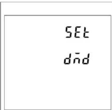
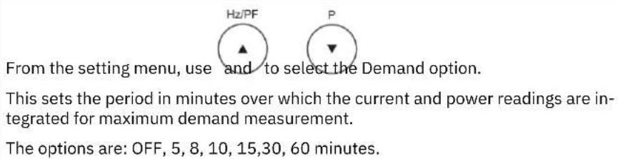
The unit provides block interval demand calculation. In this method, you select a 'block' of time that energy meter uses for the demand calculation.
You choose how the energy meter handles that block of time (interval).
Two different modes are optional.
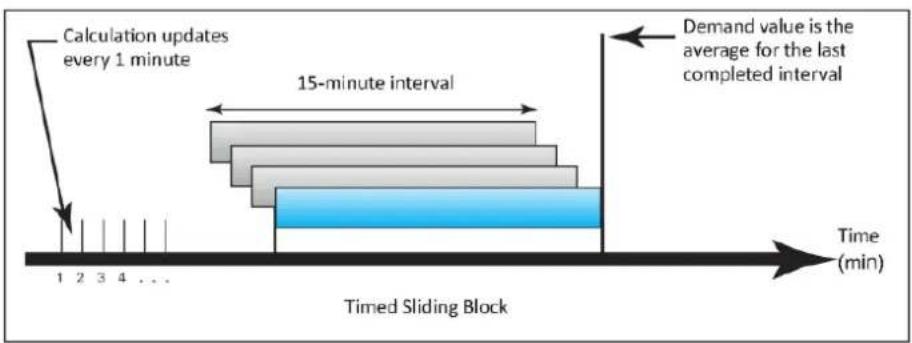
Slide Block:
Select a demand interval time (DIT) from 1 to 60 minutes (in 1 minute increments). Set the calculation update time from 1 to 59 minutes. The energy meter displays the demand value for the last completed interval.
Figure 5-1 Timed sliding Block
flowchart
graph LR
    A["Calculation updates every 1 minute"] --> B["15-minute interval"]
    B --> C["Demand value is the average for the last completed interval"]
    C --> D["Time (min)"]
    style A fill:#f9f,stroke:#333
    style B fill:#bbf,stroke:#333
    style C fill:#bfb,stroke:#333
    style D fill:#fff,stroke:#333
Fixed Block:
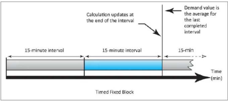
Select an interval from 1 to 60 minutes (in 1 minute increments).
The energy meter calculates an updated demand at the end of each interval.
Figure 5-2 Timed Fixed Block
5.5.1 Demand method
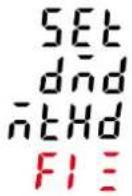
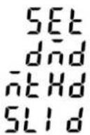 | The screen shows the Demand calculation method: Slid Options: Fix and Slid  Use to enter and calculation method. Use to enter and calculation method. |
 |  Long press to enter the routine. The setting will flash. Long press to enter the routine. The setting will flash.  Use to change itions. Use to change itions. Long press for confirmation. Long press for confirmation. |
5.5.2 Demand interval time/ Block time (DIT)
| SET dit 60 | The screen will show the currently selected integration time. Then press to enter the DIT routine. Long press to enter the setting. Use and to choose Options. Long press for confirmation. Range: 1...60 minutes, default: 60. Off means function closed. |
5.5.3 Sliding time
| SET SLID E1nE 01 | The screen will show the Sliding time for the sliding mode. The sliding time shall be set not bigger than the DIT. |
5.6 Time
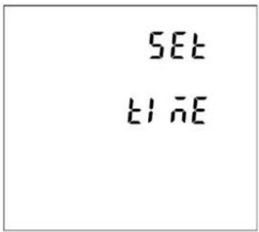 | Time setting menu:This option sets the backlight lasting time and display scroll time. From the setting menu, use Time option. From the setting menu, use Time option. |
5.6.1 Backlight lasting time
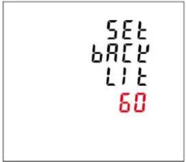 |  Long press is under the Backlit time routine, lone press for 2 settings will flash. Long press is under the Backlit time routine, lone press for 2 settings will flash.   Use to choose options, long press for confirmationOptions: ON/OFF/5/10/30/60/120 minutes. Default: 60Note:If it is set as 5, the backlit will be off in 5 minutes.If it is set as ON, the backlit will always be on. Use to choose options, long press for confirmationOptions: ON/OFF/5/10/30/60/120 minutes. Default: 60Note:If it is set as 5, the backlit will be off in 5 minutes.If it is set as ON, the backlit will always be on. |
5.6.2 Display scroll time
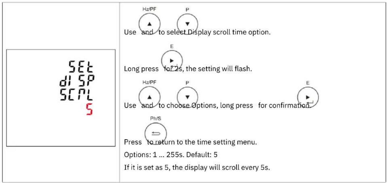
5.6.3 System RTC
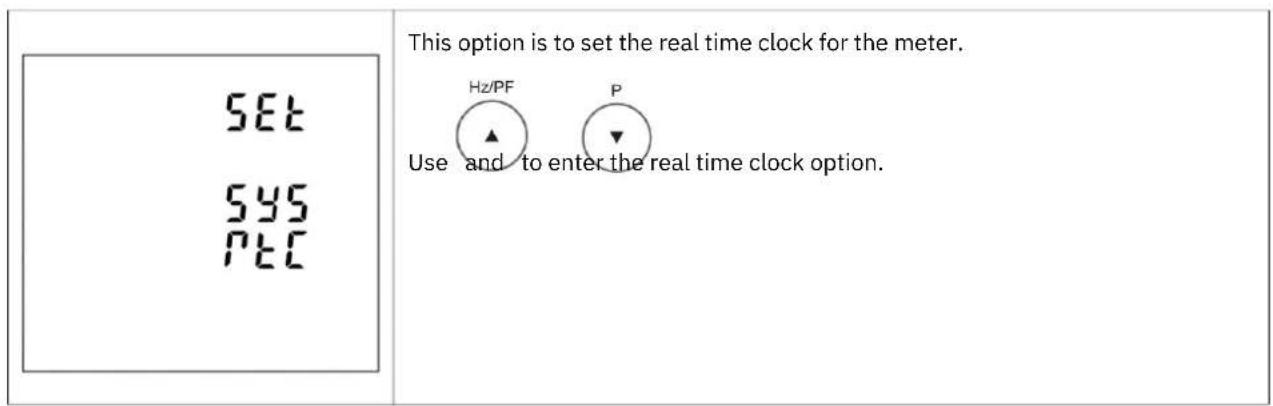
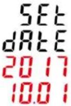 | Long press for 2s to set the date of RTC.  Use, _ _ _ _ _ _ _ _ _ _ _ _ _ _ _ _ _ _ _ _ _ _ _ _ _ _ _ _ _ _ _ _ _ _ _ _ _ _ _ _ _ _ _ _ _ _ _ _ _ _ _ _ _ _ _ _ _ _ _ _ _ _ _ _ _ _ _ _ _ _ _ _ _ _ _ _ _ _ _ _ _ _ _ _ _ _ _ _ _ _ _ _ _ _ _ _ _ _ _ _ Use, _ _ _ _ _ _ _ _ _ _ _ _ _ _ _ _ _ _ _ _ _ _ _ _ _ _ _ _ _ _ _ _ _ _ _ _ _ _ _ _ _ _ _ _ _ _ _ _ _ _ _ _ _ _ _ _ _ _ _ _ _ _ _ _ _ _ _ _ _ _ _ _ _ _ _ _ _ _ _ _ _ _ _ _ _ _ _ _ _ _ _ _ _ _ _ _ _ _ _ _ | |
 Long press not confirmation.Left picture shows 2017.10.01. (The format is YYYY.MM.DD) Long press not confirmation.Left picture shows 2017.10.01. (The format is YYYY.MM.DD) | ||
 Use or the time setting option. Use or the time setting option. Long press to set the time of RTC. Long press to set the time of RTC.  Use the hute and second. Use the hute and second. Long press nfirmation. Long press nfirmation. Press to return to the time setting menu.Left picture shows 16:20:58. (The format is HH:MM:SS) Press to return to the time setting menu.Left picture shows 16:20:58. (The format is HH:MM:SS) | ||
5.6.4 Tariff Time
 | This option is to set the time segments with different tariffs.  Use to enter real time clock option. Use to enter real time clock option. |
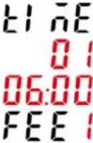 | Set the time segments and corresponding tariffs.Left picture shows:Time01 represents the time segment number, range: 01~08.06:00 represents the starting time of this time segment, format: HH:MM FEE1 represents Tariff 1, range 1~4.  Use to change a time segment number. Use to change a time segment number. Long press for 25, user can set the starting time of this time segment and tariff information. Long press for 25, user can set the starting time of this time segment and tariff information. |
5.7 System
 5y5 5y5 | System setting menu, long press to enter the setting of system.  Use _ to ch_ ,options.Options: System type, System connect, Password, Auto display scroll. Use _ to ch_ ,options.Options: System type, System connect, Password, Auto display scroll. |
5.7.1 System type
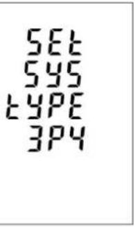 | Long press to enter the setting of system type.    Use to choose options and long press for confirmOptions: 3P4W, 3P3W, 1P2W. Use to choose options and long press for confirmOptions: 3P4W, 3P3W, 1P2W. |
5.7.2 System connec t
| This unit provides a function with Reverse connected current inputs correction setting. | |
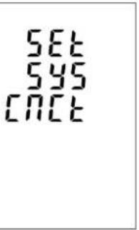 | Use to enter the setting of correction, as shown on the left picture. |
| Long press to set the setting of correction, as shown on the left picture. | |
  Useochtions. Options: Phase-1, Phase-2, Phase-3. Useochtions. Options: Phase-1, Phase-2, Phase-3. | |
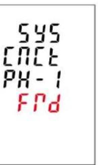 | For example: |
 Long press to enter the setting of Phase-1 correction. Long press to enter the setting of Phase-1 correction. | |
  Use under to choose options. Options: Frd (forward) and rEv (reverse), default Frd (forward) Use under to choose options. Options: Frd (forward) and rEv (reverse), default Frd (forward) | |
 Long press confirmation. Long press confirmation. |
5.7.3 Password
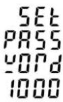 |  Use to enter the menu of password setting. Use to enter the menu of password setting. |
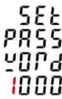 |    Use, which to use password for confirmation.Range: 0000 ... 9999, default: 1000 Use, which to use password for confirmation.Range: 0000 ... 9999, default: 1000 |
5.7.4 Auto display scroll
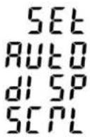 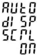 | This unit provides two methods to set the automatic display scroll. 1. Long press to enter the setting of automatic display scroll. 1. Long press to enter the setting of automatic display scroll.  Use: o ch ,otions “ON” or “OFF”. Use: o ch ,otions “ON” or “OFF”. Long press for confirmation.2. Escape the setting menu. Long press for confirmation.2. Escape the setting menu. Long press to change the automatic display scroll.For example, the screen shows the currently selected Automatic Scroll display ON. Long press to change the automatic display scroll.For example, the screen shows the currently selected Automatic Scroll display ON. |
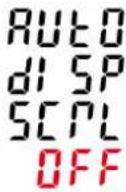 |  Long press again, then the screen shows the currently selected Automatic Scroll display OFF. Long press again, then the screen shows the currently selected Automatic Scroll display OFF. |
5.8 Digital inputs (DI)
SETdl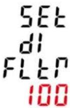 | This unit provides a function with Digital inputs setting. Long press to enter the setting of filtering time for digital inputs signal.Range: 0 ... 255ms, default: 100.For example:Left picture shows 100ms. Long press to enter the setting of filtering time for digital inputs signal.Range: 0 ... 255ms, default: 100.For example:Left picture shows 100ms. |
 | This screen is to check the counting number of each digital inputs. Long press the user can see counting numbers. Long press the user can see counting numbers. |
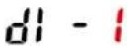 |   By using and, the user can see counting numbers of different dig-ital inputs.Left picture shows Digital input 1, counting number is 8. By using and, the user can see counting numbers of different dig-ital inputs.Left picture shows Digital input 1, counting number is 8. |
5.9 Digital outputs (DO)
  | This unit provides a function with Digital outputs setting. |
 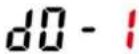 | Long press for 2s, the user can set the parameter and checking the status of DO-1.   Use to choose different Digital outputs. Use to choose different Digital outputs. |
 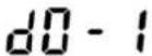  | This screen is to set the alarm information link to DO-1. |
| The Alarm can be linked to the parameters below:U1, U2, U3, Unav (Ph/N)U12, U23, U31, Uuav (Ph/Ph)I1, I2, I3, Iav, InP1, P2, P3, P-totalQ1, Q2, Q3, Q-totalS1, S2, S3, S-totalPF1, PF2, PF3, PF-totalF (frequency)Null means the Alarm is not linked to any parameter.Here, U1 is taken as an example. | |
 Long press to set the delay time of DO action.Range: 0 ... 9999ms, default: 200.Left picture shows 200ms. Long press to set the delay time of DO action.Range: 0 ... 9999ms, default: 200.Left picture shows 200ms. | |
 Long press to set the high value for DO-1 close.For example,Left picture shows HC (High value to Close) 1000V, that means when the U1 reaches to 1000V, the DO-1 will close. Long press to set the high value for DO-1 close.For example,Left picture shows HC (High value to Close) 1000V, that means when the U1 reaches to 1000V, the DO-1 will close. | |
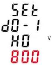 |  Long press to set the high value for DO-1 open.For example,Left picture shows HO (High value to Open) 800V, that means when the U1 drops to 800V, the DO-1 will open. Long press to set the high value for DO-1 open.For example,Left picture shows HO (High value to Open) 800V, that means when the U1 drops to 800V, the DO-1 will open. |
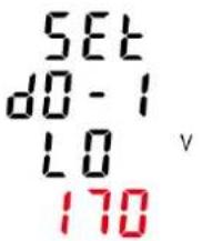 |  Long press to set the Low value for DO-1 Open.For example,Left picture shows LO (Low value to Open) 800V, that means when the U1 returns to 170V, the DO-1 will open. Long press to set the Low value for DO-1 Open.For example,Left picture shows LO (Low value to Open) 800V, that means when the U1 returns to 170V, the DO-1 will open. |
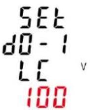 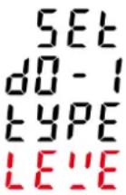 |  Long press to set the Low value for DO-1 Close.For example,Left picture shows LC (Low value to Close) 100V, that means when the U1 drops to 100V, the DO-1 will close.This screen is to set the digital output type for DO-1Left picture shows LEVE.LEVE = Level.PULS = Pulse. Long press to set the Low value for DO-1 Close.For example,Left picture shows LC (Low value to Close) 100V, that means when the U1 drops to 100V, the DO-1 will close.This screen is to set the digital output type for DO-1Left picture shows LEVE.LEVE = Level.PULS = Pulse. |
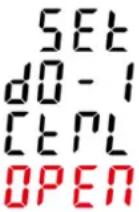 | This screen is to control the status of DO-1 relay.Left picture shows the status is OPEN.Options: OPEN, CLOSE. |
5.10 Ethernet communication
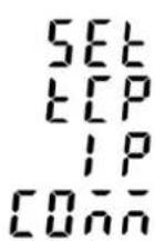 | This menu is to set the parameter for Ethernet communication. Long press to enter the setting of Ethernet communication. Long press to enter the setting of Ethernet communication. |
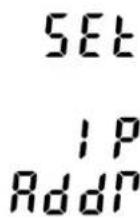 | This screen is to set the IP address. |
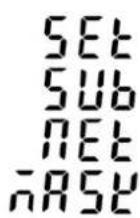 | This screen is to set Subnet Mask. |
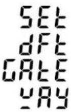 | This screen is to set the default of Gateway. |
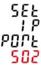 | This screen is to set the IP port. |
5.11 SOE information
The energy meter can provide SOE record, 30 events and their happen time will be saved in the SOE.
When the following events happen, it would be recorded.
- Meter power off
- Meter power on
- CT2 changed
- CT1 changed
- PT2 changed
- PT1 changed
- Energy reset
- Demand reset
- Alarm happens
| This menu is to set the sequence of event (SOE).Long press to enter the setting of SOE. | |
| Use and to check other events.For example,Left picture shows No.1 event. | |
 Long press to find the data and time when the event happened. Long press to find the data and time when the event happened. |
5.12 Reset
This unit provides a function with reset for different information. Long press to enter the setting of reset. Long press to enter the setting of reset.  Use to ch > reset options. Use to ch > reset options. | |
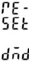
| This screen is to reset the energy information.It would reset active, reactive, apparent, import, export energy information. | |
 | This screen is to reset the demand information. It would reset current and power demand information. |
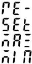 | This screen is to reset the Maximum and Minimum information. |
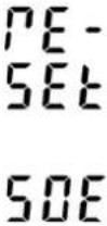 | This screen is to reset the SOE information. |
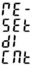 | This screen is to reset digital input counting. |
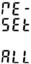 | This screen is to reset all information. |
6 Communication
6.1 Modbus RTU (Default settings)
| Address 1 | |
| Baud rate 9600 bps | |
| Parity No | |
| Stop bit 1 |
Figure 6-1 Connection assignment of Modbus/RTU
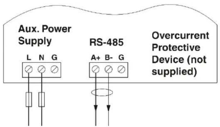
RS-485
6.2 Ethernet (Default settings)
| IP address 192.168.1.200 | |
| Subnet mask 255.255.255.0 | |
| Gateway 192.168.1.1 | |
| DHCP Off |
7 Technical data
Measurement data
Measurement principle True r.m.s. value measurement (TRMS) up to 63rd harmonic
Measurement value AC sine
Frequency range 45 ... 65Hz
Data refresh rate 1 s nominal
Voltage measurement
Input measuring range using transformer
Primary 50 ... 600000 V AC
Secondary 50 ... 600 V AC
Input measuring range, direct 87 ... 600 V AC (Ph/Ph)
Accuracy 0.2%
Current measurement, current transformer
Input current:
Primary nominal current 1 ... 9999 A AC
Secondary 1 A AC or 5 A AC
Overload capacity 6 A AC
Short-term overload 120 A for 0.5 s
Accuracy 0.2% (10% ... 120% In)
Power measurement
Accuracy, active power 0.5% (EN 61557-12)
Accuracy, active energy Class 0.5 S (EN 62053-22)
Accuracy, reactive energy Class 2 (EN 62053-23)
Supply
Supply voltage range 85 ... 275 V AC
Frequency AC sine (50/60 Hz)
Power consumption < 2W
Digital inputs
Number 4
Input resistance 10 kΩ
Maximum frequency 1 kHz
Response time 10 ms
Isolation 2.5 kV AC for 1min
Digital outputs
Number/Type 2 - electromagnetic relay
| Maximum frequency 1 kHz |
| Switching current 250 V AC at 3.0 A |
| Isolation 2.5 kV AC for 1min |
Mechanical characteristics
| Degree of Protection IP51 front display |
| Dimensions (width/height/depth) 96mm x 96mm x 70.3mm |
Connection data
Connection method Screw connection
| Conductor cross section, current / voltage / power supply |
| Tightening torque 0.5 Nm |
| Conductor cross section, |
| RS-485 / digital inputs / digital outputs |
| Tightening torque 0.2 Nm |
0.5 mm ^2 ... 2.5 mm ^2
| 0.5 mm2 ... 1.5 mm2 |
Ambient conditions
| Operating temperature -25°C ... 70°C | |
| Storage temperature -40°C ... 70°C | |
| Permissible humidity (operation) ≤95% at 50°C (non-condensing) | |
| Pollution degree 2 | |
| Altitude 2000 m | |
Electrical isolation
| Measurement category IEC 61010-1 | |
| Current inputs | Require external current transformer for insulation |
| Overvoltage category | CAT III 300 V AC |
Communications
Modbus RTU
| Communication interface | RS-485 |
| Communication address | 1 ... 247 |
| Transmission speed | 2400 ... 38400 bps |
| Response time | <100 ms |
Modbus TCP
| Communication interface | RJ45 |
| Transmission speed | 100 M bps |
Conformance
| CE-compliant | RoHS, EMC, LVD |
8 Modbus register Map
8.1 Measuring values
Table 8-1 Input Registers
| Decimal start address | Hexadecimal start address | Type Function code Format | |
| 30001 0x0000 Read 04 Float |
| Address (Register) | Input Register Parameters Hexadecimal | address | |||||
| Description Length | (bytes) | Data Format | Unit | ||||
| 30001 Phase 1 line to neutral volts. 4 Float V 00 00 | |||||||
| 30003 Phase 2 line to neutral volts. 4 Float V 00 02 | |||||||
| 30005 Phase 3 line to neutral volts. 4 Float V 00 04 | |||||||
| 30007 | Phase 1 current. | 4 | Float | A | 00 | 06 | |
| 30009 | Phase 2 current. | 4 | Float | A | 00 | 08 | |
| 30011 | Phase 3 current. | 4 | Float | A | 00 | 0A | |
| 30013 | Phase 1 active power. | 4 | Float | W | 00 | 0C | |
| 30015 | Phase 2 active power. | 4 | Float | W | 00 | 0E | |
| 30017 | Phase 3 active power. | 4 | Float | W | 00 | 10 | |
| 30019 | Phase 1 apparent power. | 4 | Float | VA | 00 | 12 | |
| 30021 | Phase 2 apparent power. | 4 | Float | VA | 00 | 14 | |
| 30023 | Phase 3 apparent power. | 4 | Float | VA | 00 | 16 | |
| 30025 | Phase 1 reactive power. | 4 | Float | VAr | 00 | 18 | |
| 30027 | Phase 2 reactive power. | 4 | Float | VAr | 00 | 1A | |
| 30029 | Phase 3 reactive power. | 4 | Float | VAr | 00 | 1C | |
| 30031 | Phase 1 power factor (1). | 4 | Float | None | 00 | 1E | |
| 30033 | Phase 2 power factor (1). | 4 | Float | None | 00 | 20 | |
| 30035 | Phase 3 power factor (1). | 4 | Float | None | 00 | 22 | |
| 30037 | Phase 1 phase angle. | 4 | Float | Degrees | 00 | 24 | |
| 30039 | Phase 2 phase angle. | 4 | Float | Degrees | 00 | 26 | |
| 30041 | Phase 3 phase angle. | 4 | Float | Degrees | 00 | 28 | |
| 30043 | Average line to neutral volts. | 4 | Float | V | 00 | 2A | |
| 30047 | Average line current. | 4 | Float | A | 00 | 2E | |
| 30049 | Sum of line currents. | 4 | Float | A | 00 | 30 | |
| 30053 Total system power. 4 Float W 00 34 | |||||
| 30057 Total system volt amps. 4 Float VA 00 38 | |||||
| 30061 Total system VAr. 4 Float VAr 00 3C | |||||
| 30063 Total system power factor (1). 4 Float None 00 3E | |||||
| 30067 Total system phase angle. 4 Float Degrees 00 42 | |||||
| 30071 Frequency of supply voltages. 4 Float Hz 00 46 | |||||
| 30073 Total import active energy. 4 Float kWh 00 48 | |||||
| 30075 Total export active energy. 4 Float kWh 00 4A | |||||
| 30077 Total import reactive energy. 4 Float kVArh 00 4C | |||||
| 30079 Total export reactive energy. 4 Float kVArh 00 4E | |||||
| 30081 Total apparent energy. 4 Float kVAh 00 50 | |||||
| 30083 Ah. 4 Float Ah 00 52 | |||||
| 30085 Total system power demand (2). 4 Float W 00 54 | |||||
| 30087 Maximum total system power demand (2). 4 Float W 00 56 | |||||
| 30089 Import active power demand 4 Float W 00 58 | |||||
| 30091 Import active power max. demand 4 Float W 00 5A | |||||
| 30093 Export active power demand 4 Float W 00 5C | |||||
| 30095 Export active power max. demand 4 Float W 00 5E | |||||
| 30101 Total system VA demand. 4 Float VA 00 64 | |||||
| 30103 Maximum total system VA demand. 4 Float VA 00 66 | |||||
| 30105 Neutral current demand. 4 Float Amps 00 68 | |||||
| 30107 Maximum neutral current demand. 4 Float Amps 00 6A | |||||
| 30109 Total system reactive power demand. (2) 4 Float VAr 00 6C | |||||
| 30111 Maximum total system reactive power demand. (2) 4 Float None 00 70 | |||||
| 30113 Phase 1 Displacement Power Factor 4 Float None 00 70 | |||||
| 30115 Phase 2 Displacement Power Factor 4 Float None 00 70 | |||||
| 30117 Phase 3 Displacement Power Factor 4 Float None 00 70 | |||||
| 30119 Total Displacement Power Factor 4 Float None 00 70 | |||||
| 30161 Voltage phase sequence (normal=1,reverse=2,phase missing =3) 4 Float None 00 A0 | |||||
| 30163 Current phase sequence (normal=1,reverse=2,phase missing =3( 4 Float None 00 A2 | |||||
| 30165 L1 Voltage Crest Factor 4 Float None 00 A4 | |||||
| 30167 L2 Voltage Crest Factor 4 Float None 00 A6 | |||||
| 30169 L3 Voltage Crest Factor 4 Float None 00 A8 | |||||
| 30183 L1 Current K Factor 4 Float None 00 B6 | |||||
| 30185 L2 Current K Factor 4 Float None 00 B8 |
| 30187 L3 Current K | Factor 4 Float None 00 BA | |||||
| 30193 | Nature of the load(Resistive =1, inductive =2,capacitive =3) | 4 Float None 00 C0 | ||||
| 30195 | Nature of L1 load(Resistive=1, inductive=2,capac- itive =3) | 4 Float None 00 C2 | ||||
| 30197 | Nature of L2 load(Resistive =1, inductive=2,capacitive =3) | 4 Float None 00 C4 | ||||
| 30199 | Nature of L3 load(Resistive =1, inductive=2,capacitive =3) | 4 Float None 00 C6 | ||||
| 30201 Line 1 to Line | 2 volts. 4 Float V 00 C8 | |||||
| 30203 Line 2 to Line | 3 volts. 4 Float V 00 CA | |||||
| 30205 Line 3 to Line | 1 volts. 4 Float V 00 CC | |||||
| 30207 Average line to line volts. 4 Float V 00 CE | ||||||
| 30225 Neutral current. 4 Float A 00 E0 | ||||||
| 30235 Phase 1 L/N volts THD | 4 Float % | 00 EA | ||||
| 30237 Phase 2 L/N volts THD | 4 Float % | 00 EC | ||||
| 30239 Phase 3 L/N volts THD | 4 Float % | 00 EE | ||||
| 30241 Phase 1 Current THD | 4 Float % | 00 F0 | ||||
| 30243 Phase 2 Current THD | 4 Float % | 00 F2 | ||||
| 30245 Phase 3 Current THD | 4 Float % | 00 F4 | ||||
| 30249 Average line to neutral volts THD. | 4 Float % | 00 F8 | ||||
| 30251 Average line current THD. | 4 Float % | 00 FA | ||||
| 30255 Total system power factor (1). | 4 Float Degrees | 00 FE | ||||
| 30259 Phase 1 current demand. | 4 Float A | 01 02 | ||||
| 30261 Phase 2 current demand. | 4 Float A | 01 04 | ||||
| 30263 Phase 3 current demand. | 4 Float A | 01 06 | ||||
| 30265 Maximum phase 1 current demand. | 4 Float A | 01 08 | ||||
| 30267 Maximum phase 2 current demand. | 4 Float A | 01 0A | ||||
| 30269 | Maximum phase 3 current demand. | 4 Float A | 01 0C | |||
| 30335 | Line 1 to line 2 volts THD. | 4 | Float | ? | 01 | 4E |
| 30337 | Line 2 to line 3 volts THD. | 4 | Float | ? | 01 | 50 |
| 30339 | Line 3 to line 1 volts THD. | 4 | Float | ? | 01 | 52 |
| 30341 | Average line to line volts THD. | 4 | Float | ? | 01 | 54 |
| 30343 Total active Energy (3) | 4 Float kWh | 01 56 | ||||
| 30345 Total reactive Energy (3) | 4 Float kVArh | 01 58 | ||||
| 30347 L1 import active Energy | 4 Float kWh | 01 5A | ||||
| 30349 L2 import active Energy | 4 Float kWh | 01 5C | ||||
| 30351 L3 import active | Energy 4 Float kWh 01 5E | |||||
| 30353 L1 export active | Energy 4 Float kWh 01 60 | |||||
| 30355 L2 export active | Energy 4 Float kWh 01 62 | |||||
| 30357 L3 export active | Energy 4 Float kWh 01 64 | |||||
| 30359 L1 total active | Energy 4 Float kWh 01 66 | |||||
| 30361 L2 total active | Energy 4 Float kWh 01 68 | |||||
| 30363 L3 total active | Energy 4 Float kWh 01 6A | |||||
| 30365 L1 import reactive energy | 4 Float kVArh 01 6C | |||||
| 30367 L2 import reactive energy | 4 Float kVArh 01 6E | |||||
| 30369 L3 import reactive energy | 4 Float kVArh 01 70 | |||||
| 30371 L1 export reactive energy | 4 Float kVArh 01 72 | |||||
| 30373 L2 export reactive energy | 4 Float kVArh 01 74 | |||||
| 30375 L3 export reactive energy | 4 Float kVArh 01 76 | |||||
| 30377 L1 total reactive energy | 4 Float kVArh 01 78 | |||||
| 30379 L2 total reactive energy | 4 Float kVArh 01 7A | |||||
| 30381 L3 total reactive energy | 4 Float kVArh 01 7C | |||||
| 30403 Voltage 2~63rd Harmonic L1 248 Float % | 01 92 | |||||
| 30527 Voltage 2~63rd Harmonic L2 248 Float % | 02 0E | |||||
| 30651 Voltage 2~63rd Harmonic L3 248 Float % | 02 8A | |||||
| 30775 Current 2~63rd Harmonic L1 248 Float % | 03 06 | |||||
| 30899 Current 2~63rd Harmonic L2 248 Float % | 03 82 | |||||
| 31023 Current 2~63rd Harmonic L3 248 Float % | 03 FE | |||||
| 31147 Voltage Total Harmonic L1 | 4 Float % | 04 7A | ||||
| 31149 Voltage Total Harmonic L2 | 4 Float % | 04 7C | ||||
| 31151 Voltage Total Harmonic L3 | 4 Float % | 04 7E | ||||
| 31153 Current Total Harmonic L1 | 4 Float % | 04 80 | ||||
| 31155 Current Total Harmonic L2 | 4 Float % | 04 82 | ||||
| 31157 Current Total Harmonic L3 | 4 Float % | 04 84 | ||||
| 31285 Voltage unbalance factor (zero-sequence) | 4 Float % | 05 04 | ||||
| 31287 Voltage unbalance factor (negative-sequence) | 4 Float % | 05 06 | ||||
| 31289 Current unbalance factor (zero-sequence) | 4 Float % | 05 08 | ||||
| 31291 Current unbalance factor (negative-sequence) | 4 Float % | 05 0A | ||||
| 32649 | Maximum value of total active power | 4 | Float | W | 0A | 58 |
| 32651 | Maximum value of total reactive power | 4 | Float | VAr | 0A | 5A |
| 32653 | Maximum value of total apparent power | 4 | Float | VA | 0A | 5C |
| 32655 | Maximum value of phase 1 active power | 4 | Float | W | 0A | 5E |
| 32657 Maximum value of phase 2 active power 4 Float W 0A 60 | |||||
| 32659 Maximum value of phase 3 active power 4 Float W 0A 62 | |||||
| 32661 Maximum value of phase 1 reactive power 4 Float VAr 0A 64 | |||||
| 32663 Maximum value of phase 2 reactive power 4 Float VAr 0A 66 | |||||
| 32665 Maximum value of phase 3 reactive power 4 Float VAr 0A 68 | |||||
| 32667 Maximum value of phase 1 apparent power 4 Float VA 0A 6A | |||||
| 32669 Maximum value of phase 2 apparent power 4 Float VA 0A 6C | |||||
| 32671 Maximum value of phase 3 apparent power 4 Float VA 0A 6E | |||||
| 32673 Maximum value of phase 1 current 4 Float A 0A 70 | |||||
| 32675 Maximum value of phase 2 current 4 Float A 0A 72 | |||||
| 32677 Maximum value of phase 3 current 4 Float A 0A 74 | |||||
| 32679 Maximum value of neutral current 4 Float A 0A 76 | |||||
| 32681 Maximum value of total currents 4 Float A 0A 78 | |||||
| 32683 Maximum value of phase 1 line to neutral voltage 4 Float V 0A 7A | |||||
| 32685 Maximum value of phase 2 line to neutral voltage 4 Float V 0A 7C | |||||
| 32687 Maximum value of phase 3 line to neutral voltage 4 Float V 0A 7E | |||||
| 32689 Maximum value of line 1 to line 2 voltage 4 Float V 0A 80 | |||||
| 32691 Maximum value of line 2 to line3 voltage 4 Float V 0A 82 | |||||
| 32693 Maximum value of line 3 to line 1 voltage 4 Float V 0A 84 | |||||
| 32695 Minimum value of total active power 4 Float W 0A 86 | |||||
| 32697 Minimum value of total reactive power 4 Float VAr 0A 88 | |||||
| 32699 Minimum value of total apparent power 4 Float VA 0A 8A | |||||
| 32701 Minimum value of phase 1 active power 4 Float W 0A 8C | |||||
| 32703 Minimum value of phase 2 active power 4 Float W 0A 8E | |||||
| 32705 Minimum value of phase 3 active power 4 Float W 0A 90 | |||||
| 32707 Minimum value of phase 1 reactive power 4 Float VAr 0A 92 | |||||
| 32709 Minimum value of phase 2 reactive power 4 Float VAr 0A 94 | |||||
| 32711 Minimum value of phase 3 reactive power 4 Float VAr 0A 96 | |||||
| 32713 Minimum value of phase 1 apparent power 4 Float VA 0A 98 | |||||
| 32715 Minimum value of phase 2 apparent power 4 Float VA 0A 9A | |||||
| 32717 Minimum value of phase 3 apparent power 4 Float VA 0A 9C | |||||
| 32719 Minimum value of phase 1 current 4 Float A 0A 9E | |||||
| 32721 Minimum value of phase 2 current 4 Float A 0A A0 | |||||
| 32723 Minimum value of phase 3 current 4 Float A 0A A2 | |||||
| 32725 Minimum value of neutral current 4 Float A 0A A4 | |||||
| 32727 Minimum value of total currents 4 Float A 0A A6 | |||||
| 32729 Minimum value of phase 1 line to neutral voltage 4 Float V 0A A8 | |||||
| 32731 Minimum value of phase 2 line to neutral voltage 4 Float V 0A AA | |||||
| 32733 Minimum value of phase 3 line to neutral voltage 4 Float V 0A AC | |||||
| 32735 Minimum value of line 1 to line 2 voltage 4 Float V 0A AE | |||||
| 32737 Minimum value of line 2 to line3 voltage 4 Float V 0A B0 | |||||
| 32739 Minimum value of line 3 to line 1 voltage 4 Float V 0A B2 | |||||
| 32763 Maximum value of total power factor 4 Float None 0A CA | |||||
| 32765 Maximum value of L1 power factor 4 Float None 0A CC | |||||
| 32767 Maximum value of L2 power factor 4 Float None 0A CE | |||||
| 32769 Maximum value of L3 power factor 4 Float None 0A D0 | |||||
| 32771 Maximum value of L1 voltage THD 4 Float % 0A D2 | |||||
| 32773 Maximum value of L2 voltage THD 4 Float % 0A D4 | |||||
| 32775 Maximum value of L3 voltage THD 4 Float % 0A D6 | |||||
| 32777 Maximum value of L1 current THD 4 Float % 0A D8 | |||||
| 32779 Maximum value of L2 current THD 4 Float % 0A DA | |||||
| 32781 Maximum value of L3 current THD 4 Float % 0A DC | |||||
| 32783 Minimum value of total power factor 4 Float None 0A DE | |||||
| 32785 Minimum value of L1 power factor 4 Float None 0A E0 | |||||
| 32787 Minimum value of L2 power factor 4 Float None 0A E2 | |||||
| 32789 Minimum value of L3 power factor 4 Float None 0A E4 | |||||
| 32791 Minimum value of L1 voltage THD 4 Float % 0A E6 | |||||
| 32793 Minimum value of L2 voltage THD 4 Float % 0A E8 | |||||
| 32795 Minimum value of L3 voltage THD 4 Float % 0A EA | |||||
| 32797 Minimum value of L1 current THD 4 Float % 0A EC | |||||
| 32799 Minimum value of L2 current THD 4 Float % 0A EE | |||||
| 32801 Minimum value of L3 current THD 4 Float % 0A F0 | |||||
| 34877 Total active energy Rate 1 | 4 | Float | kWh | 13 | 0C |
| 34879 Total active energy Rate 2 | 4 | Float | kWh | 13 | 0E |
| 34881 Total active energy Rate 3 | 4 | Float | kWh | 13 | 10 |
| 34883 Total active energy Rate 4 | 4 | Float | kWh | 13 | 12 |
| 34885 Import active energy Rate 1 | 4 | Float | kWh | 13 | 14 |
| 34887 Import active energy Rate 2 | 4 | Float | kWh | 13 | 16 |
| 34889 Import active energy Rate 3 | 4 | Float | kWh | 13 | 18 |
| 34891 Import active energy Rate 4 | 4 | Float | kWh | 13 | 1A |
| 34893 Export active energy Rate 1 | 4 | Float | kWh | 13 | 1C |
| 34895 Export active energy Rate 2 | 4 | Float | kWh | 13 | 1E |
| 34897 Export active | energy Rate 3 4 Float kWh 13 20 | |||||
| 34899 Export active | energy Rate 4 4 Float kWh 13 22 | |||||
| 34901 Total reactive | energy Rate 1 4 Float kVArh 13 24 | |||||
| 34903 Total reactive | energy Rate 2 4 Float kVArh 13 26 | |||||
| 34905 Total reactive | energy Rate 3 4 Float kVArh 13 28 | |||||
| 34907 Total reactive | energy Rate 4 4 Float kVArh 13 2A | |||||
| 34909 Import reactive | energy Rate 1 4 Float kVArh 13 2C | |||||
| 34911 Import reactive | energy Rate 2 4 Float kVArh 13 2E | |||||
| 34913 Import reactive | energy Rate 3 4 Float kVArh 13 30 | |||||
| 34915 Import reactive | energy Rate 4 4 Float kVArh 13 32 | |||||
| 34917 Export reactive | energy Rate 1 4 Float kVArh 13 34 | |||||
| 34919 Export reactive | energy Rate 2 4 Float kVArh 13 36 | |||||
| 34921 Export reactive | energy Rate 3 4 Float kVArh 13 38 | |||||
| 34923 Export reactive | energy Rate 4 4 Float kVArh 13 3A |
Comments:
- The power factor has its sign adjusted to indicate the direction of the current.
- Positive refers to forward current, negative refers to reverse current.
- The power sum demand calculation is for import - export.
- Total active energy / reactive energy equals to Import + export.
8.2 Device information and configuration
Table 8-2 Holding Registers
| Decimal start address Hexadecimal start address Function code | |
| 40001 0x0000 03/10 |
| Address Register | Description Hex | adecimal address Valid | range Mode | ||
| 40001 Dem | and time 00 00 R | read minutes | into first dem | and calculation.When the Demand time reaches the Demand pe- riod then the demand values are valid.Length: 4 bytesData Format: Float | ro |
| 40003 Dem | and period 00 02 | Write demand | period: 0~ | 60 minutes, Default 60.Range: 0...60, 0 means function closedLength: 4 bytesData Format: Float | r/w |
| 40005 Slide | time 00 04 | Default 1 min. | Range: 1 ~ (Demand Period -1).Length: 4 bytesData Format: Float | r/w | |
| 40007 Dem | and calcu- lation method | 00 06 | Default 0, | 0 = sliding block1 = fixed blockLength: 4 bytesData Format: Float | r/w |
| 40011 System type | 00 0A | Write system type: | 1 = 1P2W.2 = 3P3W.3 = 3P4W. (default)6 = 3P4W 1CT Balance load.Length: 4 bytesData Format: Float(KPPA is asked) | r/w | |
| 40015 Key | Parameter Programming Authorization (KPPA) | 00 0E Read: to get the st | status of the KPPA0 = not authorized; 1 = authorizedWrite the correct password to get KPPA, enable to program key parameters.Length: 4 bytesData Format: Float | r/w | |
| 40019 Parity and stop bit | 00 12 Write the network | port parity/stop bits for MOD-BUS Protocol0 = One stop bit and no parity, default.1 = One stop bit and even parity.2 = One stop bit and odd parity.3 = Two stop bits and no parity.Length: 4 bytesData Format: Float | r/w | ||
| 40021 Modbus address | 00 14 Write the network | port.Address: 1 to 247 for MODBUS Protocol, default 1.Length: 4 bytesData Format: Float | r/w | ||
| 40025 Password 00 18 Read: to get the p | the meterWrite: to program the new password of the meterDefault 1000.Length: 4 bytesData Format: Float | r/w | |||
| 40029 Network Baud Rate | 00 1C Write the network | port baud rate for MODBUS Protocol.0 = 2400 baud.1 = 4800 baud.2 = 9600 baud, default.3 = 19200 baud.4 = 38400 baudLength: 4 bytesData Format: Float | r/w | ||
| 40047 PT1 | 00 2E PT1 Range | 50...600000 V, Default 230 | Length: 4 bytesData Format: Float(KPPA is asked) | r/w | |
| 40049 PT2 | 00 30 PT2 Range | 50...600 V, Default 230 | Length: 4 bytesData Format: Float(KPPA is asked) | r/w | |
| 40051 CT1 | 00 32 CT1 Range | 1...9999A?Default 5? | Length: 4 bytesData Format: Float(KPPA is asked) | r/w | |
| 40053 CT2 | 00 34 CT2 Range | 1A or 5A, Default 5A | Length: 4 bytesData Format: Float(KPPA is asked) | r/w | |
| 40057 Current Direction correction (when the external CT is connected reversely) | 00 38 0 = L1 Frd, L2 Frd | L3 Frd1 = L1 Rev, L2 Frd, L3 Frd2 = L1 Frd, L2 Rev, L3 Frd3 = L1 Rev, L2 Rev, L3 Frd4 = L1 Frd, L2 Frd, L3 Rev5 = L1 Rev, L2 Frd, L3 Rev6 = L1 Frd, L2 Rev, L3 Rev7 = L1 Rev, L2 Rev, L3 RevDefault 0Length: 4 bytesData Format: Float(KPPA is asked) | r/w | ||
| 40059 Automatic Scroll Display Time | 00 3A Default 5 s. | Range: 1...255Length: 4 bytesData Format: Float | r/w | ||
| 40061 Backlit time 00 3C Default 60 min. | Range: 0...1210 means backlit always on.121 means backlit always off.Length: 4 bytesData Format: Float | r/w | |||
| 40513 DO-1 | mode 02 00 DO-1 | output mode. | 00 00 = level.00 01 = pulse.Length: 2 bytesData Format: Hex | r/w | |
| 40514 DO-2 | mode 02 01 DO-2 | output mode. | 00 00 = level.00 01 = pulse.Length: 2 bytesData Format: Hex | r/w | |
| 40521 DO-1 | pulse duration | 02 08 DO-1 | pulse duration. | Range: 50...3000ms, default 1000.Length: 2 bytesData Format: unsigned int16 | r/w |
| 40522 DO-2 | pulse duration | 02 09 DO-2 | pulse duration. | Range: 50...3000ms, default 1000.Length: 2 bytesData Format: unsigned int16 | r/w |
| 40769 DI filter time | 03 00 DI filter time. | Range: 0...255ms, default: 100.Length: 2 bytesData Format: unsigned int16 | r/w | ||
| 40770 DI-1 | count 03 01 DI-1 | count. | Length: 4 bytesData Format: unsigned int32Write 0 to reset the count. No response if write other value. | r/w | |
| 40772 DI-2 | count 03 03 DI-2 | count. | Length: 4 bytesData Format: unsigned int32Write 0 to reset the count. No response if write other value. | r/w | |
| 40774 DI-3 | count 03 05 DI-3 | count. | Length: 4 bytesData Format: unsigned int32Write 0 to reset the count. No response if write other value. | r/w | |
| 40776 DI-4 | count 03 07 DI-4 | count. | Length: 4 bytesData Format: unsigned int32Write 0 to reset the count. No response if write other value. | r/w | |
| 41025 DO-1 | Alarm Parameter (1)* | 04 00 DO-1 | Alarm parameter.(1)* Range: 0...29, and 255.Default: 255 = nullLength: 2 bytesData Format: unsigned int16 | r/w | |
| 41026 DO-1 | Action delay time | 04 01 DO-1 | Action delay time.Range: 0...9999ms, default: 200.Length: 2 bytesData Format: unsigned int16 | r/w | |
| 41027 DO-1 | HC Value (2)* | 04 02 DO-1 | High value to close.Length: 4 bytesData Format: Float | r/w | |
| 41029 DO-1 | HO Value (2)* | 04 04 DO-1 | High value to open.Length: 4 bytesData Format: Float | r/w | |
| 41031 DO-1 | LO Value (2)* | 04 06 DO-1 | Low value to open.Length: 4 bytesData Format: Float | r/w | |
| 41033 DO-1 | LC Value (2)* | 04 08 DO-1 | Low value to close.Length: 4 bytesData Format: Float | r/w | |
| 41035 DO-2 | Alarm Parameter (1)* | 04 0A DO-2 | Alarm parameter.(1)* Range: 0...29, and 255.Default: 255 = nullLength: 2 bytesData Format: unsigned int16 | r/w | |
| 41036 DO-2 | Action delay time | 04 0B DO-2 | Action delay time.Range: 0...9999ms, default: 200.Length: 2 bytesData Format: unsigned int16 | r/w | |
| 41037 DO-2 | HC Value (2)* | 04 0C DO-2 | High value to close.Length: 4 bytesData Format: Float | r/w | |
| 41039 DO-2 | HO Value (2)* | 04 0E DO-2 | High value to | open. Length: 4 bytes Data Format: Float | r/w |
| 41041 DO-2 | LO Value (2)* | 04 10 DO-2 | Low value to | open. Length: 4 bytes Data Format: Float | r/w |
| 41043 DO-2 | LC Value (2)* | 04 12 DO-2 | Low value to | close. Length: 4 bytes Data Format: Float | r/w |
| 41105 DO-1 | Status | 04 50 DO-1 | Status | 0 = Open (HO or LO) 1 = HC 2 = LC Length: 2 bytes Data Format: unsigned int16 | ro |
| 41106 DO-2 | Status | 04 51 DO-2 | Status | 0 = Open 1 = HC 2 = LC Length: 2 bytes Data Format: unsigned int16 | ro |
| 41281 SOE | -01 (3)* 05 00 SOE | -01 information; the format is: type-event cause -year-month-date -hour-min-second Length: 8 bytes Data Format: BCD | ro | ||
| 41285 SOE | -02 (3)* 05 04 SOE | -02 information; the format is: type-event cause -year-month-date -hour-min-second Length: 8 bytes Data Format: BCD | ro | ||
| 41289 SOE | -03 (3)* 05 08 SOE | -03 information; the format is: type-event cause -year-month-date -hour-min-second Length: 8 bytes Data Format: BCD | ro | ||
| 41293 SOE | -04 (3)* 05 0C SOE | -04 information; the format is:type-event cause -year-month-date -hour-min-secondLength: 8 bytesData Format: BCD | ro | ||
| 41297 SOE | -05 (3)* 05 10 SOE | -05 information; the format is:type-event cause -year-month-date -hour-min-secondLength: 8 bytesData Format: BCD | ro | ||
| 41301 SOE | -06 (3)* 05 14 SOE | -06 information; the format is:type-event cause -year-month-date -hour-min-secondLength: 8 bytesData Format: BCD | ro | ||
| 41305 SOE | -07 (3)* 05 18 SOE | -07 information; the format is:type-event cause -year-month-date -hour-min-secondLength: 8 bytesData Format: BCD | ro | ||
| 41309 SOE | -08 (3)* 05 1C SOE | -08 information; the format is:type-event cause -year-month-date -hour-min-secondLength: 8 bytesData Format: BCD | ro | ||
| 41313 SOE | -09 (3)* 05 20 SOE | -09 information; the format is:type-event cause -year-month-date -hour-min-secondLength: 8 bytesData Format: BCD | ro | ||
| 41317 SOE | -10 (3)* 05 24 SOE | -10 information; the format is:type-event cause -year-month-date -hour-min-secondLength: 8 bytesData Format: BCD | ro | ||
| 41321 SOE | -11 (3)* 05 28 SOE | -11 information; the format is:type-event cause -year-month-date -hour-min-secondLength: 8 bytesData Format: BCD | ro | ||
| 41325 SOE | -12 (3)* 05 2C SOE | -12 information; the format is: type-event cause -year-month-date -hour-min-second Length: 8 bytes Data Format: BCD | ro | ||
| 41329 SOE | -13 (3)* 05 30 SOE | -13 information; the format is: type-event cause -year-month-date -hour-min-second Length: 8 bytes Data Format: BCD | Ro | ||
| 41333 SOE | -14 (3)* 05 34 SOE | -14 information; the format is: type-event cause -year-month-date -hour-min-second Length: 8 bytes Data Format: BCD | ro | ||
| 41337 SOE | -15 (3)* 05 38 SOE | -15 information; the format is: type-event cause -year-month-date -hour-min-second Length: 8 bytes Data Format: BCD | ro | ||
| 41341 SOE | -16 (3)* 05 3C SOE | -16 information; the format is: type-event cause -year-month-date -hour-min-second Length: 8 bytes Data Format: BCD | ro | ||
| 41345 SOE | -17 (3)* 05 40 SOE | -17 information; the format is: type-event cause -year-month-date -hour-min-second Length: 8 bytes Data Format: BCD | ro | ||
| 41349 SOE | -18 (3)* 05 44 SOE | -18 information; the format is: type-event cause -year-month-date -hour-min-second Length: 8 bytes Data Format: BCD | ro | ||
| 41353 SOE | -19 (3)* 05 48 SOE | -19 information; the format is: type-event cause -year-month-date -hour-min-second Length: 8 bytes Data Format: BCD | ro | ||
| 41357 SOE | -20 (3)* 05 4C SOE | -20 information; the format is: type-event cause -year-month-date -hour-min-second Length: 8 bytes Data Format: BCD | ro | ||
| 41361 SOE | -21 (3)* 05 50 SOE | -21 information; the format is: type-event cause -year-month-date -hour-min-second Length: 8 bytes Data Format: BCD | ro | ||
| 41365 SOE | -22 (3)* 05 54 SOE | -22 information; the format is: type-event cause -year-month-date -hour-min-second Length: 8 bytes Data Format: BCD | ro | ||
| 41369 SOE | -23 (3)* 05 58 SOE | -23 information; the format is: type-event cause -year-month-date -hour-min-second Length: 8 bytes Data Format: BCD | ro | ||
| 41373 SOE | -24 (3)* 05 5C SOE | -24 information; the format is: type-event cause -year-month-date -hour-min-second Length: 8 bytes Data Format: BCD | ro | ||
| 41377 SOE | -25 (3)* 05 60 SOE | -25 information; the format is: type-event cause -year-month-date -hour-min-second Length: 8 bytes Data Format: BCD | ro | ||
| 41381 SOE | -26 (3)* 05 64 SOE | -26 information; the format is: type-event cause -year-month-date -hour-min-second Length: 8 bytes Data Format: BCD | ro | ||
| 41385 SOE | -27 (3)* 05 68 SOE | -27 information; the format is: type-event cause -year-month-date -hour-min-second Length: 8 bytes Data Format: BCD | ro | ||
| 41389 SOE | -28 (3)* 05 6C SOE | -28 information; the format is: type-event cause -year-month-date -hour-min-second Length: 8 bytes Data Format: BCD | ro | ||
| 41393 SOE | -29 (3)* 05 70 SOE | -29 information; the format is: type-event cause -year-month-date -hour-min-second Length: 8 bytes Data Format: BCD | ro | ||
| 41397 SOE | -30 (3)* 05 74 SOE | -30 information; the format is: type-event cause -year-month-date -hour-min-second Length: 8 bytes Data Format: BCD | ro | ||
| 41401 SOE | -31 (3)* 05 78 SOE | -31 information; the format is: type-event cause -year-month-date -hour-min-second Length: 8 bytes Data Format: BCD | ro | ||
| 41405 SOE | -32 (3)* 05 7C SOE | -32 information; the format is: type-event cause -year-month-date -hour-min-second Length: 8 bytes Data Format: BCD | ro | ||
| 41409 SOE | -33 (3)* 05 80 SOE | -33 information; the format is: type-event cause -year-month-date -hour-min-second Length: 8 bytes Data Format: BCD | ro | ||
| 41413 SOE | -34 (3)* 05 84 SOE | -34 information; the format is: type-event cause -year-month-date -hour-min-second Length: 8 bytes Data Format: BCD | ro | ||
| 41417 SOE | -35 (3)* 05 88 SOE | -35 information; the format is: type-event cause -year-month-date -hour-min-second Length: 8 bytes Data Format: BCD | ro | ||
| 41421 SOE | -36 (3)* 05 8C SOE | -36 information; the format is:type-event cause -year-month-date -hour-min-secondLength: 8 bytesData Format: BCD | ro | ||
| 41425 SOE | -37 (3)* 05 90 SOE | -37 information; the format is:type-event cause -year-month-date -hour-min-secondLength: 8 bytesData Format: BCD | ro | ||
| 41429 SOE | -38 (3)* 05 94 SOE | -38 information; the format is:type-event cause -year-month-date -hour-min-secondLength: 8 bytesData Format: BCD | ro | ||
| 41433 SOE | -39 (3)* 05 98 SOE | -39 information; the format is:type-event cause -year-month-date -hour-min-secondLength: 8 bytesData Format: BCD | ro | ||
| 41437 SOE | -40 (3)* 05 9C SOE | -40 information; the format is:type-event cause -year-month-date -hour-min-secondLength: 8 bytesData Format: BCD | ro | ||
| 461441 Time | F0 00 s-min-hour-week-Date-Month-Year-20 | r/w | |||
| 461445 Running time F0 04 Day-hour-minute, | r/w | ||||
| 461447 Ethernet communication parameter | F0 06 Ethernet communication parameter includes:IP address (4 bytes), subnet mask (4 bytes), default gateway (4 bytes), IP port (2 bytes).Data format:IP Address-Subnet mask-default gateway- IP port, high byte first.Default:IP Address = 192.168.1.200Subnet mask = 255.255.255.0Gate way = 192.168.1.1Length: 14 bytesData Format: Hex | r/w |
| 461455 Automatic IP address acquisition (DHCP) | F0 0E The function setting registers for automatically obtaining IP address.00 00 = Turn off automatic IP address acquisition function00 01 = Open automatic IP address acquisition functionLength: 2 bytesData Format: Hex(KPPA is asked) | r/w |
| 461456 Enable the function of reading IP address information | F0 0F Write 00 01 to initiate the acquisition of the meter's IP address information.Reading the register indicates the status of obtaining IP address information, and returning 00 00 indicates that obtaining IP address information failed; 00 01 indicates that the IP address is successfully obtained.Note: One minute after the IP address is successfully obtained, the status automatically changes to 00 00.Length: 2 bytesData Format: Hex | r/w |
| 461457 Reset historical data | F0 10 00 00 = reset demand information00 03 = reset energy information00 04 = reset max. and min. data00 05 = reset SOE information00 06 = reset DI countsLength: 2 bytesData Format: Hex | wo |
| 461697 Meter Info F1 00 Meter information: model and software versionLength: 16 bytesData Format: ASCII (Character ASCII) | ro | |||
| 463233 Tariff F7 00 Tariff number-Min-Hour | r/wTariff number: 01, 02, 03, 04Min: 00...59Hour: 00...23Length: 24 bytesData Format: BCD | |||
| 463793 Running time F9 30 Continuous working period--hourLength: 4 bytesData Format: Float | r/w | |||
| 464513 Serial number FC 00 Serial number | roLength: 4 bytesData Format: unsigned int32Note: Only read | |||
Table 8-3 Alarm parameters
| Number Alarm parameter Number Alarm parameter Number Alarm parameter | |||||
| 0 Phase 1 line to neutral volts. | 10 Phase 3 current. 20 Total system reactive | power. | |||
| 1 Phase 2 line to neutral volts. | 11 Average line current. 21 Phase 1 apparent power. | ||||
| 2 Phase 3 line to neutral volts. | 12 Neutral current. 22 Phase 2 apparent power. | ||||
| 3 Average line to neutral volts. | 13 Phase 1 active power. 23 Phase 3 apparent power. | ||||
| 4 | Line 1 to Line 2 volts. | 14 | Phase 2 active power. | 24 | Total system apparent power. |
| 5 | Line 2 to Line 3 volts. | 15 | Phase 3 active power. | 25 | Phase 1 power factor. |
| 6 | Line 3 to Line 1 volts. | 16 | Total system power. | 26 | Phase 2 power factor. |
| 7 | Average line to line volts. | 17 | Phase 1 reactive power. | 27 | Phase 3 power factor. |
| 8 | Phase 1 current. | 18 | Phase 2 reactive power. | 28 | Total system power factor. |
| 9 | Phase 2 current. | 19 | Phase 3 reactive power. | 29 | Frequency of supply voltages. |
Comments:
(1)* Alarm parameters (Table 8-3)
(2)* Please make sure during the setting: HC>HO >LO >LC
(3)* SOE information format: type-event cause-year-month-date-hour-min-second.
Type: 0...67, and 99. (Table 8-4)
Event cause:
0 = null. 1 and 2 refer to the cause of event:
1 = HC alarm caused event.
2 = LC alarm caused event
Year: the year when event happened. For example, 2017, year=17.
Month: the month when event happened.
Date: the date when event happened.
Hour: the hour when event happened.
Min: the Minute when event happened
Second: the second when event happened
Table 8-4 SOE description
| Number Event description Number Event description Number Event description | |||||
| 0 L1 voltage alarm 13 Phase 1 active power | alarm | 26 Phase 2 | power factor alarm | ||
| 1 L2 voltage alarm 14 Phase 2 active power | alarm | 27 Phase 3 | power factor alarm | ||
| 2 L3 voltage alarm 15 Phase 3 active power | alarm | 28 Total power factor alarm | |||
| 3 L-N average voltage alarm 16 Total active power alarm 29 Frequency alarm | |||||
| 4 L1-2 Voltage alarm 17 Phase 1 reactive power | alarm | 60 Power on | |||
| 5 L2-3 Voltage alarm 18 Phase 2 reactive power | alarm | 61 Power off | |||
| 6 L3-1 Voltage alarm 19 Phase 3 reactive power | alarm | 62 CT2 change | |||
| 7 L-L Average voltage alarm 20 Total reactive power alarm | 63 CT1 change | ||||
| 8 Phase 1 current alarm 21 Phase 1 apparent power alarm | 64 PT2 change | ||||
| 9 Phase 2 current alarm 22 Phase 2 apparent power alarm | 65 PT1 change | ||||
| 10 Phase 3 current alarm 23 Phase 3 apparent power alarm | 66 Energy reset | ||||
| 11 Average current alarm 24 Total apparent power alarm | 67 Demand info reset | ||||
| 12 Neutral current alarm 25 Phase 1 power factor alarm | 99 Null | ||||
8.3 Read input status of Digital inputs
Table 8-5 DI status
| Decimal start address Hexadecimal start address Function code | |
| 10001 0x0000 02 |
| AddressRegister | Description Hexadecimal address | Valid range Mode | |||
| 10001 DI-1 status | 00 00 DI-1 status, 1=ON, 0=OFF | Length: 1 bitData Format: Binary | ro | ||
| 10002 DI-2 status | 00 01 DI-2 status, 1=ON, 0=OFF | Length: 1 bitData Format: Binary | ro | ||
| 10003 DI-3 status | 00 02 DI-3 status, 1=ON, 0=OFF | Length: 1 bitData Format: Binary | ro | ||
| 10004 DI-4 status | 00 03 DI-4 status, 1=ON, 0=OFF | Length: 1 bitData Format: Binary | ro | ||
8.4 Read coil status of Digital inputs
Table 8-6 DO status
| Decimal start address Hexadecimal start address Function code | |
| 00001 0x0000 01 |
| Address Register | Description Hexadecimal address | Valid range Mode | |||
| 00001 DO-1 status | 00 00 DO-1 status, 1=ON, 0=OFF | Length: 1 bitData Format: Binary | ro | ||
| 00002 DO-2 status | 00 01 DO-2 status, 1=ON, 0=OFF | Length: 1 bitData Format: Binary | ro | ||
8.5 Force Single Coil
Table 8-7 Control DO
| Decimal start address Hexadecimal start address Function code | |
| 00001 0x0000 05 |
| Address Register | Description Hexadecimal address | Valid range Mode | |||
| 00001 Control DO | 1 00 00 0xFF00=ON, 0x0000 | =OFF | Length: 2 bytesData Format: Hex | w | |
| 00002 Control DO | 2 00 01 0xFF00=ON, 0x0000 | =OFF | Length: 2 bytesData Format: Hex | w | |
For example:
1. Read Input Register — Read "Phase 1 line to neutral volts"
Request: 01 04 00 00 00 02 71 CB
01 = Meter address
04 = Function code
00 = High byte of registers starting address
00 = Low byte of registers starting address
00 = High byte of registers number
02 = Low byte of registers number
71 = CRC Low
CB = CRC High
Response: 01 04 04 43 66 33 34 1B 38
01 = Meter address
04 = Function code
04= Byte count
43 = Data, (High Word, High Byte)
66 = Data, (High Word, Low Byte)
33 = Data, (Low Word, High Byte)
34 = Data, (Low Word, Low Byte)
1B = CRC Low
38 = CRC High
Note: 43 66 33 34(Hex) = 230.2 (Floating point)
2. Write Holding Registers — Write "System type = 4"
Request: 01 10 00 0A 00 02 04 40 80 00 00 67 F8
01 = Meter address
10 = Function code
00 = High byte of registers starting address
0A = Low byte of registers starting address
00 = High byte of registers number
02 = Low byte of registers number
04 = Byte Count
40 = Data, (High Word, High Byte)
80 = Data, (High Word, Low Byte)
00 = Data, (Low Word, High Byte)
00 = Data, (Low Word, Low Byte)
67 = CRC Low
F8 = CRC High
Note: 40 80 00 00 (Hex) = 4 (Floating point)
Response: 01 10 00 0A 00 02 61 CA
01 = Meter address
10 = Function code
00 = High byte of registers starting address
OA = Low byte of registers starting address
00 = High byte of registers number
02 = Low byte of registers number
61 = CRC Low
CA = CRC High
3. Read Input Status — Read "DI1\~4 status"
Request: 01 02 00 00 00 04 79 C9
01 = Meter address
02 = Function code
00 = High byte of registers starting address
00 = Low byte of registers starting address
00 = High byte of read DI number
04 = Low byte of read DI number
79 = CRC Low
C9 = CRC High
Response: 01 02 01 03 E1 89
01 = Meter address
02 = Function code
01 = Byte Count
03 = Data, (DI status)
E1 = CRC Low
89 = CRC High
Note: Data=0 x 03 = 0000 0011 (Binary Value).
Bit 0 refers to the status of DI-1. The value is 1, which means DI-1 is on.
Bit 1 refers to the status of DI-2. The value is 1, which means DI-2 is on.
Bit 2 refers to the status of DI-3. The value is 0, which means DI-3 is off.
Bit 3 refers to the status of DI-4. The value is 0, which means DI-4 is off.
A Appendixes
A 1 List of figures
Section 2
Figure 2-1: Operating and indicating example ....8
Section 3
Figure 3-1: Operating and indicating example ....9
Figure 3-2: Pin assignment example .... 10
Section 5
Figure 5-1: Timed sliding Block 22
Figure 5-2: Timed Fixed Block 23
Section 6
Figure 6-1: Connection assignment of Modbus/RTU 43
A 2 List of tables
Section 2
Table 2-1: Product overview ....7
Section 8
Table 8-1: Input Registers....46
Table 8-2: Holding Registers....54
Table 8-3: Alarm parameters 66
Table 8-4: SOE description....67
Table 8-5: DI status....68
Table 8-6: DO status....68
Table 8-7: Control DO....69
Please observe the following notes
General Terms and Conditions of Use for technical documentation
Phoenix Contact reserves the right to alter, correct, and/or improve the technical documentation and the products described in the technical documentation at its own discretion and without giving prior notice, insofar as this is reasonable for the user. The same applies to any changes that serve the purpose of technical progress.
The receipt of technical documentation (in particular user documentation) does not constitute any further duty on the part of Phoenix Contact to furnish information on modifications to products and/or technical documentation. You are responsible to verify the suitability and intended use of the products in your specific application, in particular with regard to observing the applicable standards and regulations. All information made available in the documentation data is supplied without any accompanying guarantee, whether expressly mentioned, implied or tacitly assumed.
In general, the provisions of the current General Terms and Conditions of Phoenix Contact apply exclusively, in particular as concerns any warranty liability.
This manual, including all illustrations contained herein, is copyright protected. Any changes to the contents or the publication of extracts of this document are prohibited.
Phoenix Contact reserves the right to register its own intellectual property rights for the product identifications of Phoenix Contact products that are used here. Registration of such intellectual property rights by third parties is prohibited.
Other product identifications may be afforded legal protection, even where they may not be indicated as such.
How to contact us
Internet
Up-to-date information on Phoenix Contact products and our Terms and Conditions can be found on the Internet at: phoenixcontact.com
Make sure you always use the latest documentation. It can be downloaded at: phoenixcontact.com/products
Subsidiaries
If there are any problems that cannot be solved using the documentation, please contact your Phoenix Contact subsidiary. Subsidiary contact information is available at phoenixcontact.com.
Published by Phoenix Contact GmbH & Co. KG
Phoenix Contact Development and Manufacturing, Inc. 586 Fulling Mill Road Middletown, PA 17057 USA
Should you have any suggestions or recommendations for improvement of the contents and layout of our manuals, please send your comments to: tecdoc@phoenixcontact.com
Phoenix Contact GmbH & Co. KG
Flachsmarktstraße 8
32825 Blomberg, Germany
Phone: +49 5235 3-00
Fax: +49 5235 3-41200
Email: info@phoenixcontact.com
phoenixcontact.com
- EE EMpro - energy measuring devices for front panel installation
- User manual
- Table of contents
- For your safety ....5
- Devices description....7
- Mounting and installation....9
- Operation.... 13
- Configuration.... 15
- For your safety
- Identification of warning notes
- DANGER
- WARNING
- CAUTION
- Qualification of users
- Field of application of the product
- Intended use
- Product changes
- Safety notes
- Devices description
- Product overview
- Operating and indicating elements
- Mounting and installation
- Mounting
- Connection assignment
- Grid types
- Operation
- Start mode
- Configuration
- Opening setting mode
- Communication
- Address setting
- Baud rate
- Stop bit
- CT
- CT2
- CT1
- PT
- PT2
- PT1
- Demand
- Slide Block:
- Fixed Block:
- Demand method
- Demand interval time/ Block time (DIT)
- Sliding time
- Time
- Backlight lasting time
- Display scroll time
- System RTC
- Tariff Time
- System
- System type
- System connec t
- Digital inputs (DI)
- Digital outputs (DO)
- Ethernet communication
- SOE information
- Reset
- Communication
- Modbus RTU (Default settings)
- Ethernet (Default settings)
- Technical data
- Measurement data
- Voltage measurement
- Current measurement, current transformer
- Power measurement
- Supply
- Digital inputs
- Modbus register Map
- Measuring values
- Comments:
- Device information and configuration
- Read input status of Digital inputs
- Read coil status of Digital inputs
- Force Single Coil
- For example:
- Read Input Register — Read "Phase 1 line to neutral volts"
- Write Holding Registers — Write "System type = 4"
- Response: 01 10 00 0A 00 02 61 CA
- Read Input Status — Read "DI1\~4 status"
- Request: 01 02 00 00 00 04 79 C9
- Response: 01 02 01 03 E1 89
- A Appendixes
- A 1 List of figures
- Section 2
- Section 3
- Section 5
- Section 6
- A 2 List of tables
- Section 8
- Please observe the following notes
- General Terms and Conditions of Use for technical documentation
- How to contact us
- Internet
- Subsidiaries
Brand : Phoenix Contact
Model : MM-EE-EEM-MA550
Category : Measurement