
EEM-EM157-EE - Measurement Phoenix Contact - Free user manual and instructions
Find the device manual for free EEM-EM157-EE Phoenix Contact in PDF.


| Product Type | MID Energy Meter (Single-Phase) |
| Brand | Phoenix Contact |
| Model | EEM-EM157-EE |
| Order No. | 1311993 |
| Measurement Type | Bidirectional (import/export) |
| Rated Voltage (UN) | 230 V AC |
| Voltage Range | 80%...120% UN (184...276 V AC) |
| Frequency | 50 Hz |
| Maximum Current (Imax) | 45 A (direct measurement) |
| Accuracy (Active Energy) | Class B per EN 50470-3 / Class 1 per EN 62053-21 |
| Accuracy (Reactive Energy) | Class 2 per EN 62053-23 |
| MID Compliance | Yes (Directive 2014/32/EU) |
| Communication Interface | RS-485, Modbus/RTU protocol |
| Baud Rate | 1200...19200 bps (configurable) |
| Pulse Outputs | 2 passive opto-isolated outputs; 1 configurable, 1 fixed (1000 imp/kWh) |
| Display | Backlit LCD |
| Mounting | DIN rail (DIN 43880) |
| Protection Degree (Front) | IP51 (when installed in IP51 cabinet or higher) |
| Protection Degree (Connection) | IP20 |
| Operating Temperature | -40 °C to 70 °C |
| Storage Temperature | -40 °C to 70 °C |
| Power Consumption | 10 VA (2 W) |
| Safety Class | II (double insulation) |
| Pollution Degree | 2 |
| Flame Resistance (Housing) | UL94 V0 |
| Maximum Cable Cross-Section | 10 mm² (measurement), 1.5 mm² (other) |
| Maintenance | Clean with damp cloth; switch off before cleaning; no abrasive agents |
| Repairability | Repairs only by manufacturer; no user serviceable parts |
Frequently Asked Questions - EEM-EM157-EE Phoenix Contact
User questions about EEM-EM157-EE Phoenix Contact
0 question about this device. Answer the ones you know or ask your own.
Ask a new question about this device
Download the instructions for your Measurement in PDF format for free! Find your manual EEM-EM157-EE - Phoenix Contact and take your electronic device back in hand. On this page are published all the documents necessary for the use of your device. EEM-EM157-EE by Phoenix Contact.
USER MANUAL EEM-EM157-EE Phoenix Contact
MID energy meters
User manual
UM EN EEM-EM157-EE
Order No. 1311993
User manual MID energy meters
UM EN EEM-EM157-EE, Revision 02
2023-07-01
This user manual is valid for:
Designation Order No.
EEM-EM157-EE 1311993
Table of contents
1 For your safety....5
1.1 Labeling of warning notes.... 5
1.2 Qualification of users....5
1.3 Field of application of the product.... 5
1.3.1 Intended use 5
1.3.2 Foreseeable misuse 5
1.3.3 Product changes 6
1.4 Safety notes 6
2 Device description....7
2.1 Scope of supply....7
2.2 Operating and indication elements 8
2.3 MID conformity 8
3 Quick start guide....8
4 Mounting and installation....9
4.1 Snapping the device onto the DIN rail....9
4.2 Network type 10
4.3 Modbus/RTU installation 11
4.4 Sealing 12
5 Configuration....12
5.1 Setting mode 12
5.2 Opening setting mode 13
5.3 Parameters in setting mode.... 13
5.4 Leave setting mode 13
6 Operation....14
6.1 Start mode....14
6.2 Operating mode.... 14
6.3 Communication 15
6.4 Outputs....16
7 Technical data....16
7.1 Dimensions....16
7.2 Technical data....17
MID energy meters
7.3 MID Data 18
8 Modbus register....20
8.1 Measuring values ...... 20
8.2 Device information and configuration 22
A Appendixes....25
A 1 List of figures ...... 25
A 2 List of tables ...... 27
1 For your safety
Read this user manual carefully and keep it for future reference.
1.1 Labeling of warning notes

This symbol indicates hazards that could lead to personal injury.
There are three signal words indicating the severity of a potential injury.
DANGER
Indicates a hazard with a high risk level. If this hazardous situation is not avoided, it will result in death or serious injury.
WARNING
Indicates a hazard with a medium risk level. If this hazardous situation is not avoided, it could result in death or serious injury.
CAUTION
Indicates a hazard with a low risk level. If this hazardous situation is not avoided, it could result in minor or moderate injury.

This symbol together with the NOTE signal word warns the reader of actions that might cause property damage or a malfunction.

Here you will find additional information or detailed sources of information.
1.2 Qualification of users
The use of products described in this user manual is oriented exclusively to:
– Electrically skilled persons or persons instructed by them. The users must be familiar with the relevant safety concepts of automation technology as well as applicable standards and other regulations
– Qualified application programmers and software engineers. The users must be familiar with the relevant safety concepts of automation technology as well as applicable standards and other regulations.
1.3 Field of application of the product
1.3.1 Intended use
MID energy meters may only be used to measure electric characteristic values in applications that meet the specified technical data.
1.3.2 Foreseeable misuse
MID energy meters with direct measurement are not suitable for use with voltage transformers or current transformers.
1.3.3 Product changes
Changes or modifications to hardware and software of the device are not permitted.
Incorrect operation or modifications to the device can endanger your safety or damage the device. Do not repair the device yourself. If the device is defective, please contact Phoenix Contact.
1.4 Safety notes
The "exclamation mark" on the device labeling means that you need to:
Read the installation note in its entirety. Follow the installation note to avoid impairing the intended protection.
- The installation, operation, and maintenance work must be completed by a qualified electrician. Follow the installation instructions as described. When installing and operating the device, the applicable regulations and safety directives (including national safety directives), as well as general technical regulations must be observed.
- Use an appropriate voltage measuring device to ensure that no voltage is present.
- Install the device in accordance with instructions described in the installation notes. Accessing circuits within the device is prohibited.
– Repairs may only be carried out by the manufacturer. - Only clean the device with a suitable damp cloth. Switch the device off before cleaning and do not use abrasive agents or solvents.
- Ensure that all connection terminals are connected correctly to prevent the device from being damaged.
- Observe the maximum permissible voltages (276V AC) and network frequency (50Hz).
2 Device description
The device is a single-phase energy meter with backlight LCD display. It can measure voltage, current, frequency, power, power factor, active and reactive energy, imported and exported energy, etc.
The energy values provided by the energy meters can be used for billing purposes with MID approval.
The device supports maximum 45A direct measurement, with 2 pulse outputs and RS-485 interface.
2.1 Scope of supply
Figure 2-1 Scope of supply
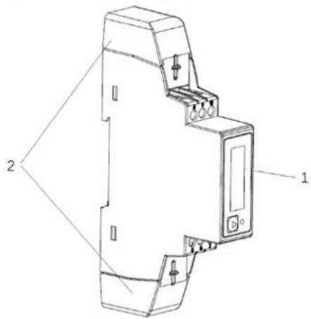
1 Energy meter, certified in accordance with MID directive 2 2x covers
2.2 Operating and indication elements
Figure 2-2 Operating and indication elements
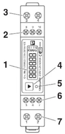
1 LCD display
2 Modbus interface
3 Neutral conductor input↑ and output↓
4 Next/Enter key
5 Pulse LED
6 Pulse outputs
7 Line conductor input↑ and output↓
2.3 MID conformity
– MID conformity refers to compliance with Directive 2014/32/EU.
- In terms of MID conformity, only Total import active energy and Total export active energy is calibrated.
- The device contains additional functions that are informative and do not play a role in the sense of MID conformity.
- The product label on the side seals the device in terms of MID conformity.
- After installation and commissioning, the covers with sealing must be applied. (see Section 4.4, "Sealing").
3 Quick start guide
After the voltage is applied, the device enters start mode. It will do self-test and then display device information.
Following start mode, the device automatically switches to operating mode default display energy values.
Navigation
| Next/Enter key – In operating mode:Scroll through the displayed pagesEnter setting mode: long press *In setting mode: Change setting valueMove to next setting menu itemEnter edit mode: long press * |
* Long press means to keep pressing the key for at least 3 seconds.
Configuring parameters
Parameters are configured in setting mode, see Section 5.1, "Setting mode"
1 Press Next/Enter key for at least 3 seconds to enter setting mode.
2 Configure the parameters, see Section 5.3, "Parameters in setting mode"
4 Mounting and installation
4.1 Snapping the device onto the DIN rail
The device is snapped onto a DIN rail in the control cabinet. The measuring position can be freely selected, but will be determined by the readability of the LCD.
Figure 4-1 Snapping the device onto the DIN rail
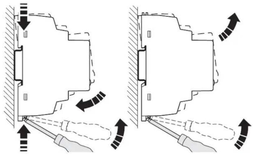
natural_image
Technical diagram showing two mechanical assembly configurations with directional arrows indicating motion (no text or symbols)4.2 Network type
Figure 4-2 Connection
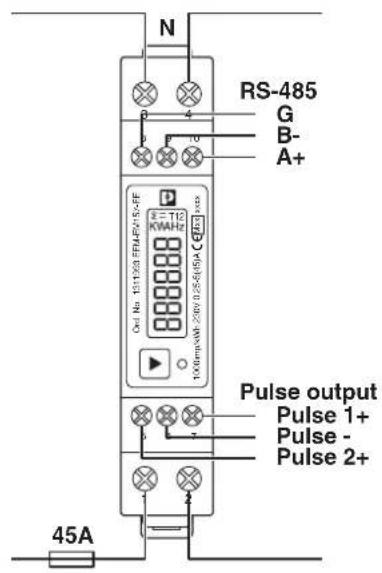
- L input↑
- L output↓
- Neutral conductor input↑ and output↓
- Neutral conductor input↑ and output↓
- Pulse output 2+
- Pulse output -
- Pulse output 1+
- RS-485 GND
- RS-485 B-
- RS-485 A+
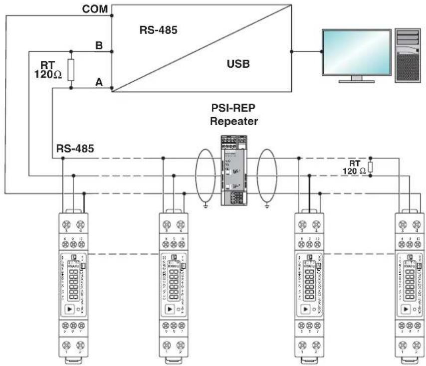
4.3 Modbus/RTU installation
Figure 4-3 Modbus/RTU network
flowchart
graph TD
    COM["COM"] --> RS-485["RS-485"]
    RS-485 --> USB["USB"]
    USB --> Display["Computer"]
    RS-485 --> RS-4851["RS-485"]
    RS-4851 --> PSI-REP["PSI-REP Repeater"]
    PSI-REP --> Display
    Display --> RT1["RT 120 Ω"]
    RT1 --> RS-4851
    RS-4851 --> RS-4852["RS-485"]
    RS-4852 --> RS-4853["RS-485"]
    RS-4853 --> RS-4854["RS-485"]
    RS-4854 --> RS-4855["RS-485"]
    RS-4855 --> RS-4856["RS-485"]
    RS-4856 --> RS-4857["RS-485"]
    RS-4857 --> RS-4858["RS-485"]
    RS-4858 --> RS-4859["RS-485"]
    RS-4859 --> RS-4860["RS-486"]
    RS-4860 --> RS-4861["RS-486"]
    RS-4861 --> RS-4862["RS-486"]
    RS-4862 --> RS-4863["RS-486"]
    RS-4863 --> RS-4864["RS-486"]
    RS-4864 --> RS-4865["RS-486"]
    RS-4865 --> RS-4866["RS-486"]
    RS-4866 --> RS-4867["RS-486"]
    RS-4867 --> RS-4868["RS-486"]
    RS-4868 --> RS-4869["RS-486"]
    RS-4869 --> RS-4870["RS-486"]
    RS-4870 --> RS-4871["RS-486"]
    RS-4871 --> RS-4872["RS-486"]
    RS-4872 --> RS-4873["RS-486"]
    RS-4873 --> RS-4874["RS-486"]
    RS-4874 --> RS-4875["RS-486"]
    RS-4875 --> RS-4876["RS-486"]
    RS-4876 --> RS-4877["RS-486"]
    RS-4877 --> RS-4878["RS-486"]
    RS-4878 --> RS-4879["RS-486"]
    RS-4879 --> RS-487A["RS-486A"]
    RS-487A --> RS-487B["RS-486B"]
    RS-487B --> RS-487C["RS-486C"]
    RS-487C --> RS-487D["RS-486D"]
    RS-487D --> RS-487E["RS-486E"]
    RS-487E --> RS-487F["RS-486F"]
    RS-487F --> RS-487G["RS-486G"]
    RS-487G --> RS-487H["RS-486H"]
    RS-487H --> RS-487I["RS-486I"]
    RS-487I --> RS-487J["RS-486J"]
    RS-487J --> RS-487K["RS-486K"]
    RS-487K --> RS-487L["RS-486L"]
    RS-487L --> RS-487M["RS-486M"]
    RS-487M --> RS-487N["RS-486N"]
    RS-487N --> RS-487O["RS-486O"]
    RS-487O --> RS-487P["RS-486P"]
    RS-487P --> RS-487Q["RS-486Q"]
    RS-487Q --> RS-487R["RS-486R"]
    RS-487R --> RS-487S["RS-486S"]
    RS-487S --> RS-487T["RS-486T"]
    RS-487T --> RS-487U["RS-486U"]
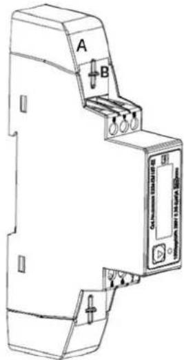
4.4 Sealing
1 Insert the upper cover (A).
2 Insert the seal cord through the hole on the device (B).
3 Tighten the cord so that the seal is located directly on the upper cover.
4 Repeat these steps for the lower cover.
Figure 4-4 Sealing
5 Configuration
This section describes how you can access the relevant setting mode and configure the parameters, e.g. the parameters of the integrated communication interface.
5.1 Setting mode
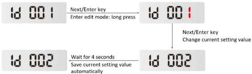
To scroll through setting menu items:
1 Press Next/Enter key.
To change the displayed value:
1 Keep pressing Next/Enter key for at least 3 seconds to enter edit mode. The value flashes.
2 Press Next/Enter key to change setting value.
3 Wait for 4 seconds to save current setting value of current setting menu item.
Next setting value flashes automatically if there is more than one value in the setting menu item.
4 After all setting values of current setting menu item have been saved automatically, it exits edit mode and no value flashes.
Figure 5-1 To change the displayed values
flowchart
graph TD
    A["1d 001"] -->|Next/Enter key\nEnter edit mode: long press| B["1d 001"]
    B -->|Next/Enter key\nChange current setting value| C["1d 002"]
    C -->|Wait for 4 seconds\nSave current setting value automatically| D["1d 002"]
5.2 Opening setting mode
Press Next/Enter key for at least 3 seconds to enter setting mode.
5.3 Parameters in setting mode
The following display pages are available.
To scroll through setting menu items or change displayed values, see Section 5.1, "Setting mode".
Figure 5-2 Setting mode

* Other parameters can be set via RS-485 Modbus RTU communication.
5.4 Leave setting mode
If there is no operation in setting mode for more than 10 seconds, it will back to operating mode default display automatically.
6 Operation
6.1 Start mode
After the voltage is applied, the device enters start mode. It will do self-test and then display device information.
Figure 6-1 Full screen
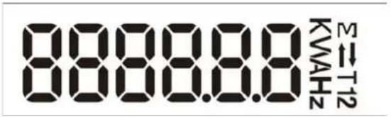
Table 6-1 Display pages: Start mode
| Menu item Description | |
| Display segments All display segments | |
| 0201.01 Software version information (subject to in kind) | |
6.2 Operating mode
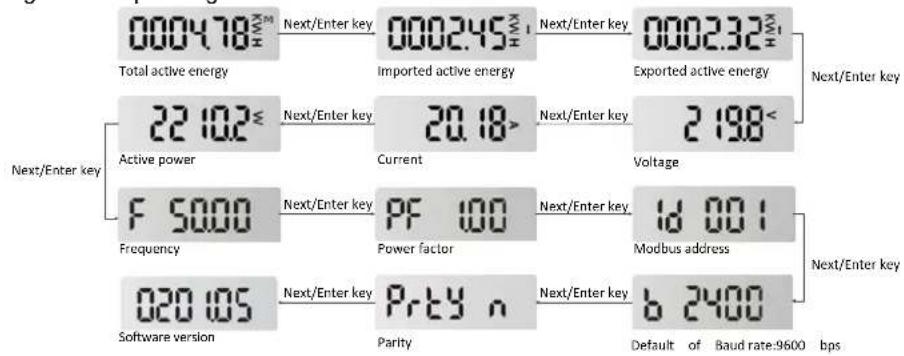
Following start mode, the device automatically switches to operating mode default display energy page. The following display pages are shown in operating mode.
To scroll through the displayed pages, press Next/Enter key.
Figure 6-2 Operating mode
other
| Component | Next/Enter Key | Value | | :--- | :--- | :--- | | Total active energy | Next/Enter key | 0004.78±0.98 | | Total active energy | Imported active energy | 0002.45±1.1 | | Total active energy | Exported active energy | 0002.32±1.1 | | Active power | Next/Enter key | 22.102±1.6 | | Active power | Current | 20.18+ | | Voltage | Next/Enter key | 2.198< | | Frequency | Next/Enter key | F 5000 | | Frequency | Power factor | PF 100 | | Modbus address | Next/Enter key | Id 001 | | Software version | Next/Enter key | 020.105 | | Software version | Parity | Prty n | | Modbus address | Next/Enter key | b 2400 | | Modbus address | Parity | b 2400 (Default of Baud rate:9600 bps) | Next/Enter key: Next/Enter key Next/Enter key: Next/Enter key6.3 Communication
The RS-485 interface is used for the local remote readout with the Modbus/RTU protocol. During this process, the measuring device is the server and the PC or controller is the client. Connect a terminal resistance RT=120Ω (0.25W min.) at the start and end of the network. The maximum length for transmission is 1000m at a speed of 1200 bps. A maximum of 32 electrical nodes can be connected, including the controller. Broadcast mode (address 0) is supported
Table 6-2 Setting range and default settings of Modbus RTU communication
| Parameters Setting range Default settings | ||
| Address 1...247 1 | ||
| Baud rate 1200 bps, 2400 bps,4800bps, 9600 bps,19200 bps | 9600 | |
| Parity None, even, odd none | ||
| Stop bit * 1, 2 | 1 | |
* For stop bit, it can't be configured directly in setting mode on the device, but can be set via RS-485 interface.
Figure 6-3 Modbus/RTU network
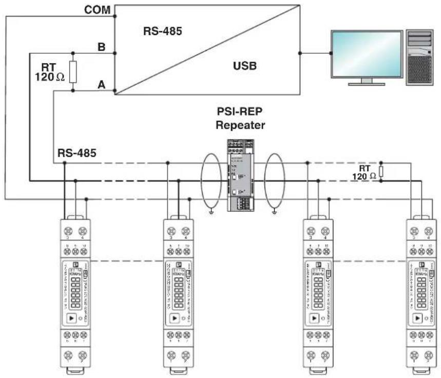
flowchart
graph TD
    COM["COM"] --> RS-485["RS-485"]
    RS-485 --> USB["USB"]
    USB --> RT1["RT 120 Ω"]
    RT1 --> RS-485
    RS-485 --> RS-485A["A"]
    RS-485 --> RS-485B["B"]
    RS-485 --> RS-485C["RS-485"]
    RS-485 --> RS-485D["RS-485"]
    RS-485 --> RS-485E["RS-485"]
    RS-485 --> RS-485F["RS-485"]
    RS-485 --> RS-485G["RS-485"]
    RS-485 --> RS-485H["RS-485"]
    RS-485 --> RS-485I["RS-485"]
    RS-485 --> RS-485J["RS-485"]
    RS-485K["RS-485"] --> RT1
    RS-485K --> RT2
    RS-485K --> RT3
    RS-485K --> RT4
    RS-485K --> RT5
    RS-485K --> RT6
    RS-485K --> RT7
    RS-485K --> RT8
    RS-485K --> RT9
    RS-485K --> RT10
    RS-485K --> RT11
    RS-485K --> RT12
    RS-485K --> RT13
    RS-485K --> RT14
    RS-485K --> RT15
    RS-485K --> RT16
    RS-485K --> RT17
    RS-485K --> RT18
    RS-485K --> RT19
    RS-485K --> RT20
    RS-485K --> RT21
    RS-485K --> RT22
    RS-485K --> RT23
    RS-485K --> RT24
    RS-485K --> RT25
    RS-485K --> RT26
    RS-485K --> RT27
    RS-485K --> RT28
    RS-485K --> RT29
    RS-485K --> RT30
    RS-485K --> RT31
    RS-485K --> RT32
    RS-485K --> RT33
    RS-485K --> RT34
    RS-485K --> RT35
    RS-485K --> RT36
    RS-485K --> RT37
    RS-485K --> RT38
    RS-485K --> RT39
    RS-485K --> RT40
    RS-485K --> RT41
    RS-485K --> RT42
    RS-485K --> RT43
    RS-485K --> RT44
    RS-485K --> RT45
    RS-485K --> RT46
    RS-485K --> RT47
    RS-485K --> RT48
    RS-485K --> RT49
    RS-485K --> RT50
    RS-485K --> RT51
    RS-485K --> RT52
    RS-485K --> RT53
    RS-485K --> RT54
    RS-485K --> RT55
    RS-485K --> RT56
    RS-485K --> RT57
    RS-485K --> RT58
    RS-485K --> RT59
    RS-485K --> RT60
    RS-485K --> RT61
    RS-485K --> RT62
    RS-485K --> RT63
    RS-485K --> RT64
    RS-485K --> RT65
    RS-485K --> RT66
    RS-485K --> RT67
    RS-485K --> RT68
    RS-485K --> RT69
    RS-485K --> RT70
    RS-485K --> RT71
    RS-485K --> RT72
    RS-485K --> RT73
    RS-485K --> RT74
    RS-485K --> RT75
    RS-485K --> RT76
    RS-485K --> RT77
    RS-485K --> RT78
    RS-485K --> RT79
    RS-485K --> RT80
6.4 Outputs
The device provides two pulse outputs. Both pulse outputs are passive type.
Pulse output 1 is configurable. The pulse output 1 can be set to generate pulses to represent total / import / export kWh or kVArh.
The pulse constant can be set to generate 1 pulse per:
0.001 kWh/kVArh (default)
0.01 kWh/kVArh
0.1kWh/kVArh
1 kWh/kVArh
Pulse width: 200/100/60ms(default)
Pulse output 2 is non-configurable. It is fixed at total kWh. The constant is 1000imp/kWh. Its width is fixed at 60ms.
* For pulse output 1, it can't be configured directly in setting mode on the device, but can be configured via RS-485 interface.
7 Technical data
7.1 Dimensions
Figure 7-1 Dimensions
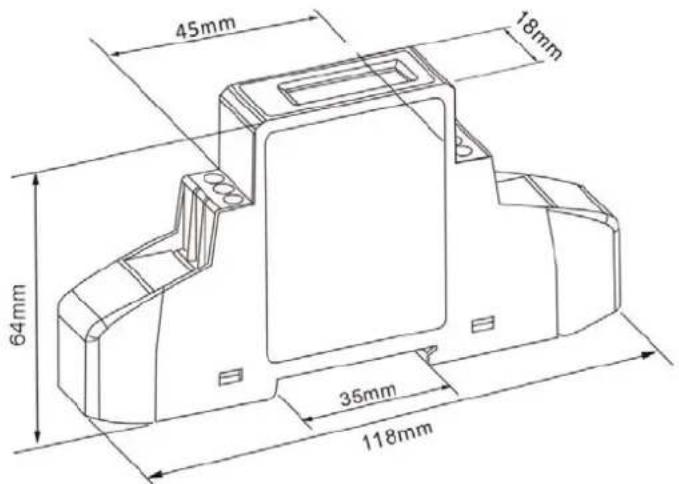
7.2 Technical data
Table 7-1 technical data
| Measuring input data | |
| Voltage UN 230 V | |
| Input voltage range 80%...120% UN | |
| Power consumption 10 VA (2 W) | |
| Frequency 50 Hz | |
| Auxiliary voltage Device is supplied by the measuring circuit | |
| Starting current Ist 0.02 A | |
| Minimum current Imin 0.25 A | |
| Transient current ltr 0.5 A | |
| Nominal current lref 5 A | |
| Maximum current Imax 45 A | |
| Measurement connection data | |
| Measurement connection 2.5...10 mm ^2 (1.5 Nm) | |
| Other connections | 0.5...1.5 mm ^2 (0.2 Nm) |
| Electric strength as per EN 50470-1 | 1.2 μs/50 μs at 6 kV |
| Electric strength as per EN 50470-3, 7.2 | 4 kV for 1 minute |
| Ambient conditions | |
| Mechanical environment | M1 |
| Electromagnetic environ-ment | E2 |
| Operation temperature | -40 °C...70 °C |
| Storage temperature | -40 °C...70 °C |
| Humidity | Max. 90%, non-condensing |
| Degree of protection-front | IP51 if mounted in a control cabinet with IP51 degree of protection or higher |
| Degree of protection-connection | IP20 |
| Internal/external meter type | Internal |
| Meter type | Bidirectional |
| Safety | |
| Pollution degree | 2 |
| Protection class as per EN 50470-1 | II |
| Flame resistance-housing | UL94 V0 |
| Accuracy | ||
| Real energy as per EN 50470-3 | Class B | |
| Real energy as per EN 62053-21 | Class 1 | |
| Reactive energy as per EN 62053-23 | Class 2 | |
| Housing | ||
| Standard DIN 43880 | ||
| Metrological LED | ||
| Pulse output 1 Pulse output 2 | ||
| Meter constant Configurable | 1000 imp/kWh | |
| Communication | ||
| Standard RS 485 | ||
| Protocol Modbus/RTU | ||
| Speed 1200...19200 bps | ||
| Parameters Address, speed, parity, stop | ||
| Outputs | ||
| Pulse output 1 Pulse output 2 | ||
| Meter constant Configurable | 1000 imp/kWh | |
| Pulse width Configurable 60 ms | ||
| Type Passive opto-isolated | ||
| Maximum voltage 27 V DC | ||
| Maximum current 27 mA DC | ||
7.3 MID Data
Table 7-2 MID data
| Accuracy | Class B (EN 50470-3) |
| Voltage UN | 230 V |
| Rated frequency fN | 50 Hz |
| Cosine φ | 0.5 inductive...0.8 capacitive |
| Starting current Ist | 0.02 A |
| Minimum current Imin 0.25 A | |
| Transient current Itr | 0.5 A |
| Nominal current Iref | 5 A |
| Maximum current Imax | 45 A |
| Operation temperature | -40 °C...70 °C (-40 °F...158 °F) |
| Relative humidity | ≤90%, non-condensing |
| Electromagnetic ambient conditions | E2 |
Table 7-2 MID data [...]
| Mechanical ambient conditions M1 | |
| Type of application Interior space counter | |
| Protection class To ensure that protection against dust and water is provided in accordance with the specific standards as per MID, the energy meter must be installed in a housing or control cabinet with protection class IP51 (or higher). | |
8 Modbus register
Table 8-1 The format for each byte in RTU mode
| Coding system: 8-bit per byte | |
| Data format: 4 bytes (2 registers) per parameter | Floating point format (to IEEE 754) if there is no special note.Most significant register first (Default). The default may be changed if required |
| Error Check Field: 2 byte Cyclical Redundancy Check (CRC) | |
| Framing: 1 start bit | 8 data bits, least significant bit sent first1 bit for even/odd parity (or no parity)1 stop bit if parity is used, 1 or 2 bits if no parity |
The device can transfer a maximum of 10 values in a single transaction. Therefore, the maximum number of registers requestable is 20. Exceeding this limit will prompt the device to generate an exception response.
8.1 Measuring values
Table 8-2 Measuring values
| Decimal start address | Hexadecimal start address | TypeFunctions Format | ||
| 30001 0x0000 | Read | 04 | Float |
| Decimal address | Hexadecimal address | Number of registers | Description | Unit | Data type |
| 30001 | 0x0000 | 2 | Voltage | V | Float |
| 30007 | 0x0006 | 2 | Current | A | Float |
| 30013 | 0x000C | 2 | Active power | W | Float |
| 30019 | 0x0012 | 2 | Apparent power | VA | Float |
| 30025 | 0x0018 | 2 | Reactive power | VAr | Float |
| 30031 | 0x001E | 2 | Power factor | None | Float |
| 30071 | 0x0046 | 2 | Frequency | Hz | Float |
| 30073 | 0x0048 | 2 | Import active energy | kWh | Float |
| 30075 | 0x004A | 2 | Export active energy | kWh | Float |
| 30077 | 0x004C | 2 | Import reactive energy | kVArh | Float |
| 3007930085 0x0054 2 Total system power de- | 0x004E | 2mand | Export reactive energyW | kVArhF | FloatI |
| 30087 0x0056 2 Maximum total system | power demand | W | F | I | |
| 30089 0x0058 2 Import system power de- | mand | W | F | I | |
| 30091 0x005A 2 Maximum Import system | power demand | W | F | I | |
| 30093 0x005C 2 Export system power de- | mand | W | F | I | |
| 30095 0x005E 2 Maximum Export system | power demand | W | F | I | |
| 30259 0x0102 2 Current demand A Float | |||||
| 30265 0x0108 2 Maximum current de- | mand | A | F | I | |
| 30343 0x0156 2 Total active energy kWh Float | |||||
| 30345 0x0158 2 Total reactive energy kVArh Float |
8.2 Device information and configuration
Table 8-3 Device information and configuration
| Decimal start address Hexadecimal start address Functions | |||||
| 40003 0x0002 03/10 | |||||
| Decimal address | Hexadecimal address | Number of registers | Description Type Data type | ||
| 40003 0x0002 2 | Demand period | 0, 5, 8, 10, 15, 20, 30, 60minsDefault 60 mins | r/w Float | ||
| 40013 0x000C 2 | Pulse 1 width | 60, 100, 200msDefault 60ms | r/w Float | ||
| 40019 0x0012 2 | Network parity stop | 1: stop bit 1, even parity2: stop bit 1, odd parity3: stop bit 2, none parityDefault 1 | r/w Float | ||
| 40021 0x0014 2 | Meter ID | 1...247Default 1 | r/w Float | ||
| 40029 0x001C 2 | Baud rate | 0: 2400 bps1: 4800 bps2: 9600 bps3: 19200 bps5: 1200 bpsDefault 2 | r/w Float | ||
| 40087 0x0056 2 | Pulse output 1 energy type | 0001: import active energy0002: total active energy (import+export)0004: export active energy0005: import reactive energy0006: total reactive energy (import+export)0008: export reactive energyDefault 0004 | r/w Float | ||
| 461457 0xF010 | 1 Reset | 00 00: reset demand info | wo Hex | ||
| 463745 0xF900 | 2 Time of scroll display | 0...30s configurableDefault 0s | r/w BCD | ||
| 463761 0xF910 | 2 Pulse output 1 | 0000: 0.001kWh/kVArh0001: 0.01kWh/ kVArh0002: 0.1kWh/ kVArh0003: 1kWh/ kVArhDefault 0000 | r/w Hex | ||
| 463777 0xF920 | 2 Measurement mode | 0001: mode 1, total=import0002: mode 2,total=import+export0003: mode 3,total=import-exportDefault 0002 | r/w Hex | ||
| 464513 0xFC00 | 2 Serial number ro Ulnt32 | ||||
A Appendixes
A 1 List of figures
Section 2
Figure 2-1: Scope of supply ....7
Figure 2-2: Operating and indication elements ....8
Section 4
Figure 4-1: Snapping the device onto the DIN rail 9
Figure 4-2: Connection .... 10
Figure 4-3: Modbus/RTU network 11
Figure 4-4: Sealing .... 12
Section 5
Figure 5-1: To change the displayed values .... 13
Figure 5-2: Setting mode ....13
Section 6
Figure 6-1: Full screen 14
Figure 6-2: Operating mode ....14
Figure 6-3: Modbus/RTU network ..... 15
Section 7
Figure 7-1: Dimensions ...... 16
A 2 List of tables
Section 6
Table 6-1: Display pages: Start mode....14
Table 6-2: Setting range and default settings of Modbus RTU communication .... 15
Section 7
Table 7-1: technical data .... 17
Table 7-2: MID data....18
Section 8
Table 8-1: The format for each byte in RTU mode....20
Table 8-2: Measuring values....20
Table 8-3: Device information and configuration....22
Please observe the following notes
General terms and conditions of use for technical documentation
Phoenix Contact reserves the right to alter, correct, and/or improve the technical documentation and the products described in the technical documentation at its own discretion and without giving prior notice, insofar as this is reasonable for the user. The same applies to any technical changes that serve the purpose of technical progress.
The receipt of technical documentation (in particular user documentation) does not constitute any further duty on the part of Phoenix Contact to furnish information on modifications to products and/or technical documentation. You are responsible to verify the suitability and intended use of the products in your specific application, in particular with regard to observing the applicable standards and regulations. All information made available in the technical data is supplied without any accompanying guarantee, whether expressly mentioned, implied or tacitly assumed.
In general, the provisions of the current standard Terms and Conditions of Phoenix Contact apply exclusively, in particular as concerns any warranty liability.
This manual, including all illustrations contained herein, is copyright protected. Any changes to the contents or the publication of extracts of this document is prohibited.
Phoenix Contact reserves the right to register its own intellectual property rights for the product identifications of Phoenix Contact products that are used here. Registration of such intellectual property rights by third parties is prohibited.
Other product identifications may be afforded legal protection, even where they may not be indicated as such.
How to contact us
Internet
Up-to-date information on Phoenix Contact products and our Terms and Conditions can be found on the Internet at: phoenixcontact.com
Make sure you always use the latest documentation. It can be downloaded at: phoenixcontact.net/products
Subsidiaries
If there are any problems that cannot be solved using the documentation, please contact your Phoenix Contact subsidiary. Subsidiary contact information is available at phoenixcontact.com.
Published by PHOENIX CONTACT GmbH & Co. KG
PHOENIX CONTACT Asia-Pacific (Nanjing) Co., Ltd. No.36 Phoenix Rd, Jiangning Development Zone 211100 Nanjing CHINA
Should you have any suggestions or recommendations for improvement of the contents and layout of our manuals, please send your comments to: tecdoc@phoenixcontact.com
PHOENIX CONTACT GmbH & Co. KG
Flachsmarktstraße 8
32825 Blomberg, Germany
Phone: +49 5235 3-00
Fax: +49 5235 3-41200
E-mail: info@phoenixcontact.com
phoenixcontact.com
- MID energy meters
- User manual MID energy meters
- Table of contents
- For your safety....5
- Device description....7
- Quick start guide....8
- Mounting and installation....9
- Configuration....12
- Operation....14
- Technical data....16
- For your safety
- Labeling of warning notes
- DANGER
- WARNING
- CAUTION
- Qualification of users
- Field of application of the product
- Intended use
- Foreseeable misuse
- Product changes
- Safety notes
- Device description
- Scope of supply
- Operating and indication elements
- MID conformity
- Quick start guide
- Mounting and installation
- Snapping the device onto the DIN rail
- Network type
- Modbus/RTU installation
- Sealing
- Configuration
- Setting mode
- Opening setting mode
- Parameters in setting mode
- Leave setting mode
- Operation
- Start mode
- Operating mode
- Communication
- Outputs
- Technical data
- Dimensions
- Technical data
- MID Data
- Modbus register
- Measuring values
- Device information and configuration
- A Appendixes
- A 1 List of figures
- Section 2
- Section 4
- Section 5
- Section 6
- Section 7
- A 2 List of tables
- Section 8
- Please observe the following notes
- General terms and conditions of use for technical documentation
- How to contact us
- Internet
- Subsidiaries
- Published by PHOENIX CONTACT GmbH & Co. KG
Brand : Phoenix Contact
Model : EEM-EM157-EE
Category : Measurement