
EEM-PM157-SLP - Measurement Phoenix Contact - Free user manual and instructions
Find the device manual for free EEM-PM157-SLP Phoenix Contact in PDF.


User questions about EEM-PM157-SLP Phoenix Contact
0 question about this device. Answer the ones you know or ask your own.
Ask a new question about this device
Download the instructions for your Measurement in PDF format for free! Find your manual EEM-PM157-SLP - Phoenix Contact and take your electronic device back in hand. On this page are published all the documents necessary for the use of your device. EEM-PM157-SLP by Phoenix Contact.
USER MANUAL EEM-PM157-SLP Phoenix Contact
650 kW DC energy meter
User manual
User manual
650 kW DC energy meter
UM EN DC energy meter, Revision 00
2023-08-25
This user manual is valid for:
Type Description Item number
EEM-PM157-SLP 650 kW DC energy meter with SLIP communication 1269236
EEM-RS485-PCM Communication adapter for DC-METER VIEW 1551889
Table of contents
1 For your safety....5
1.1 Identification of warning notes .... 5
1.2 Qualification of users....5
1.3 Field of application of the product.... 5
1.3.1 Intended use 5
1.3.2 Foreseeable misuse 6
1.3.3 Product changes ...... 6
1.4 Safety notes 6
2 Device description....7
2.1 Abbreviations....8
2.2 Information on the device 8
2.3 Operating and indication elements ...... 9
2.3.1 LED 10
2.3.2 LCD 10
2.4 Communication interface.... 12
2.5 System architecture.... 13
3 Quick-start guide 15
4 Mounting and installation....17
4.1 Snapping the device onto the DIN rail.... 17
4.2 Installation....18
4.3 Cover and seal 19
5 Configuration....21
5.1 Application configuration 21
5.2 Assembly configuration 23
6 Operation....25
6.1 Device statuses....25
6.1.3 Operation mode 26
6.2 Internal display state machine 27
6.2.1 Selftest state 28
6.2.2 Info state 28
6.2.3 Public key state 29
6.2.4 Operation state 29
6.2.5 Charging state 31
6.2.6 Charging summary state 32
6.2.7 Eichlog state 33
6.2.8 Eichlog memory full 34
6.2.9 Fatal error state 34
6.3 Line loss energy calculation.... 36
6.4 Energy flow....37
6.5 Charging session.... 38
6.6 Clock 40
6.7 Eichlog....41
6.8 External display....41
7 Technical data 43
7.1 Product specification 43
7.2 Dimensions....45
7.3 Applicable technical standards.... 46
A Registers 47
A 1 Device information.... 47
A 2 Status word .... 49
A 3 Device control.... 50
A 4 Energy and instantaneous registers .... 51
A 5 Charging session.... 52
A 6 Charging history .... 55
A 7 Eichlog (calibration law).... 57
A 8 Commands in operation mode .... 59
B Firmware....61
B 1 Metering firmware structure.... 61
B 2 Application firmware structure 62
B 3 Security measures on the application controller 64
B 4 Security measures on the metering controller.... 64
C List of figures and list of tables....65
C 1 List of figures 65
C 2 List of tables 67
D Glossary of terms 69
1 For your safety
Read this manual carefully and keep it for future reference.
1.1 Identification of warning notes

This symbol indicates hazards that could lead to personal injury.
There are three signal words indicating the severity of a potential injury.
DANGER
Indicates a hazard with a high risk level. If this hazardous situation is not avoided, it will result in death or serious injury.
WARNING
Indicates a hazard with a medium risk level. If this hazardous situation is not avoided, it could result in death or serious injury.
CAUTION
Indicates a hazard with a low risk level. If this hazardous situation is not avoided, it could result in minor or moderate injury.

This symbol together with the NOTE signal word warns the reader of actions that might cause property damage or a malfunction.

Here you will find additional information or detailed sources of information.
1.2 Qualification of users
The use of products described in this manual is oriented exclusively to:
- Electrically skilled persons or persons instructed by them. The users must be familiar with the relevant safety concepts of automation technology as well as applicable standards and other regulations.
– Qualified application programmers and software engineers. The users must be familiar with the relevant safety concepts of automation technology as well as applicable standards and other regulations.
1.3 Field of application of the product
1.3.1 Intended use
The DC energy meters may only be used to measure electric characteristic values in applications that meet the specified technical data.
1.3.2 Foreseeable misuse
The DC energy meters are not suitable for use with voltage transformers.
Only apply loads to the measuring inputs of the transformer measuring devices as specified in the connection scheme. Direct measurements at the measuring inputs of the transformer measuring devices must be avoided.
1.3.3 Product changes
Modifications to hardware and firmware of the device are not permitted.
Incorrect operation or modifications to the device can endanger your safety or damage the device. Do not repair the device yourself. If the device is defective, please contact Phoenix Contact.
1.4 Safety notes

CAUTION:
The "exclamation mark" on the device labeling means that you need to:
Read the installation notes in their entirety. Follow the installation notes to avoid impairing the intended protection.
- Installation, operation, and maintenance may only be carried out by qualified electricians. Follow the installation instructions as described.
- When installing and operating the device, observe the applicable regulations and safety directives (including national safety directives), as well as the generally recognized technical regulations.
- Observe the safety information, conditions, and limits of use specified in the product information. Comply with them.
- Use an appropriate voltage measuring device to ensure that no voltage is present.
- Install the device in accordance with the instructions described in the installation notes. Accessing circuits within the device is prohibited.
- The measuring device is maintenance-free. Repairs may only be carried out by the manufacturer.
- Only clean the device with a suitable damp cloth. Switch the device off before cleaning and do not use abrasive agents or solvents.
- Ensure that all connection terminals are connected correctly, to prevent the device from being damaged.
- Observe the maximum permissible voltages of 1000 V DC.

The symbol with the crossed-out trash can indicate that this item must be collected and disposed of separately. Phoenix Contact or our service partners will take the item back for free disposal. For information on the available disposal options, visit phoenixcontact.com. Collect and dispose of included batteries separately. Delete personal data before returning the item.
2 Device description
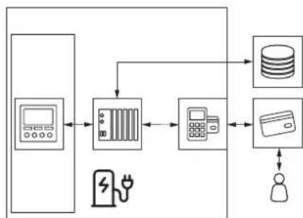
The EEM-PM157-SLP is a DC energy meter for direct installation in e-mobility charging stations. It provides the measurement data records with a timestamp, loading process data, and digital signature, enabling the billing of charging sessions in accordance with the legal requirements. Furthermore, all charging sessions are permanently stored in the internal data storage of the DC energy meter.
Figure 2-1 Schematic representation of the charging point structure
flowchart
graph TD
    A["User Interface"] --> B["Server"]
    B --> C["Database"]
    C --> D["User Interface"]
    D --> E["Database"]
    E --> F["User Interface"]
    F --> G["Database"]
    G --> H["User Interface"]
    H --> I["Database"]
    I --> J["User Interface"]
    J --> K["Database"]
    K --> L["User Interface"]
    L --> M["Database"]
    M --> N["User Interface"]
    N --> O["Database"]
    O --> P["User Interface"]
    P --> Q["Database"]
    Q --> R["User Interface"]
    R --> S["Database"]
    S --> T["User Interface"]
    T --> U["Database"]
    U --> V["User Interface"]
    V --> W["Database"]
    W --> X["User Interface"]
    X --> Y["Database"]
    Y --> Z["User Interface"]
According to Figure 2-1, the DC energy meter acquires and stores measurement data and acts as a measurement data signer as part of the measuring capsule. The connection between the main controller of the charging station and the DC energy meter is realized by an RS-485 interface. All signed, OCMF (open charge metering format) formatted datasets have to be forwarded unchanged by the station controller. This way, signature, and datasets are always transmitted together. The user authentication process should be performed according to the OCMF applicable standard. See Section "Applicable technical standards" on page 46 for details.
After completing a charging session, the user has access to all session-related data sets by the communication interfaces. By means of a transparency software application, the signed data sets can be verified for billing purposes. All start and stop values of each individual charging session are persistently stored within the internal flash storage of the DC energy meter. All data sets obtained by the DC energy meter contain a second index and a timestamp set by the charging station controller. The mentioned timestamp is a so called "Info clock". This excludes a time-based tariffing. Charging session datasets are visualized after the charging session on the display of the DC energy meter.
Through a transparency software application, the customer can check each charging session invoiced individually. Furthermore, such an application visualizes the datasets of the charging sessions during a billing period and shows the status of the signature verification and the amount of energy consumed.
2.1 Abbreviations
The following table explains the meaning of the abbreviations used in the product name.
Table 2-1 Abbreviations used in the product name
| EEM- P | M 1 | 5 | 7 | -SLP | ||||
| EEM- Electrical energy measurement | ||||||||
| P Position in power series | ||||||||
| M Verified metering device | ||||||||
| 1 Category 1, DIN rail installation | ||||||||
| 5 RS-485 interface | ||||||||
| 7 | Direct voltage and current measurement | |||||||
| -SLP Serial line internet protocol | ||||||||
2.2 Information on the device
Figure 2-2 Information on the device
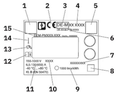
1 QR-Code item website
2 CE marking
3 Metrology marking and year, for example, DE-M 23
4 Notified body ID number, for example, 1948
5 QR-Code public key
6 Type-examination certificate, for example, DE-23-M-PTB-0021
7 Serial number, for example, 28259214
8 QR-Code serial number
9 Impulse of metrological LED
10 Year of production, for example, 2023
11 Technical nominal data
12 Documents available
13 Energy direction
14 Single phase
15 Item designation number, for example, EEM-PM157-SLP Ord.No.: 1269236
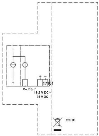
Figure 2-3 Lateral printing on the DC energy meter
2.3 Operating and indication elements
Figure 2-4 Operating and indication elements
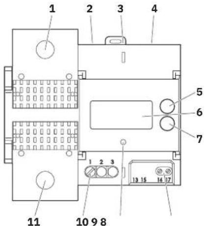
1 Negative current terminal
2 PHOENIX CONTACT DC-METER VIEW interface (on top)
3 Charge station controller interface (on top)
4 Charge station controller interface (on top)
5 Upper button
6 LCD
7 Lower button
8 Power supply
9 Metrological LED
10 Voltage terminal
11 Positive current terminal
2.3.1 LED
The DC energy meter has one pulse LED, which is capable of displaying the active mains energy or the compensated device energy with 1000 I_mp/kWh . The LED is controlled by the metering part.
Accuracy test
The accuracy of the DC energy meter can be checked with the pulse LEDs. For testing, the following quantity of minimum pulses - dependent on the load - are recommended.
If the DC energy meter is checked by reading out the energy register values via the communication interface, a minimum measuring time of 4.5 min and a minimum amount of energy of 300 Wh must be observed.
Table 2-2 Accuracy table
| Load Pulses | |
| I_max | 10 |
| I_ref | 5 |
| I_tr | 5 |
| I_st | 1 |
2.3.2 LCD
The LCD is a dot-matrix display in the format 37.5 mm x 17 mm.
Figure 2-5 Schematic illustration of the dot-matrix display (unit: (mm))
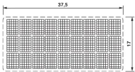
Table 2-3 Number of digits
| Element Number of digits | |
| Energy 7.2 | |
| Line loss resistance 5.4 | |
| Instantaneous value 8.1 |
Display symbols
During operation state, charging and charging summary state some symbols can be visible on the display. These symbols extend the displayed information with DC energy meter status information. The following symbols can be displayed:
Table 2-4 Display symbols
| Symbol Meaning | |
 | Production mode is active — available during production of the DC energy meter. |
 | Assembly mode is active — available during assembly of the charging point. |
 | Charging transactionWhen blinks continuously — in charging state.When permanently on — in charging summary state. |
 | Measurement modeLine loss energy measurement mode is active — DC energy meter calculates the line losses according to a given line impedance. |
 | Start current reached for A+Current measured by the DC energy meter reached the starting threshold — at this point, the DC energy meter starts measuring. |
2.4 Communication interface
There are three RS-485 interfaces of type RJ12.
– RJ12-1 and RJ12-2 used for future communication with SMGW (smart meter gateway) modules.
The two jacks are connected internally and can be used for a daisy-chain connection of several DC energy meters on a metrological network.
– RJ12-3 is designed for the communication with the charge station.
Currently there is no firmware support for a SMGW, therefore the DC energy meter provides its standard communication interface also on these jacks.
Figure 2-6 Pinout of the RS-485 interface
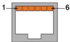
1 RS-485 bus (-)
2 Power supply input 12 V DC
3 GND
4 Not used
5 Not used
6 RS-485 bus (+)
2.5 System architecture
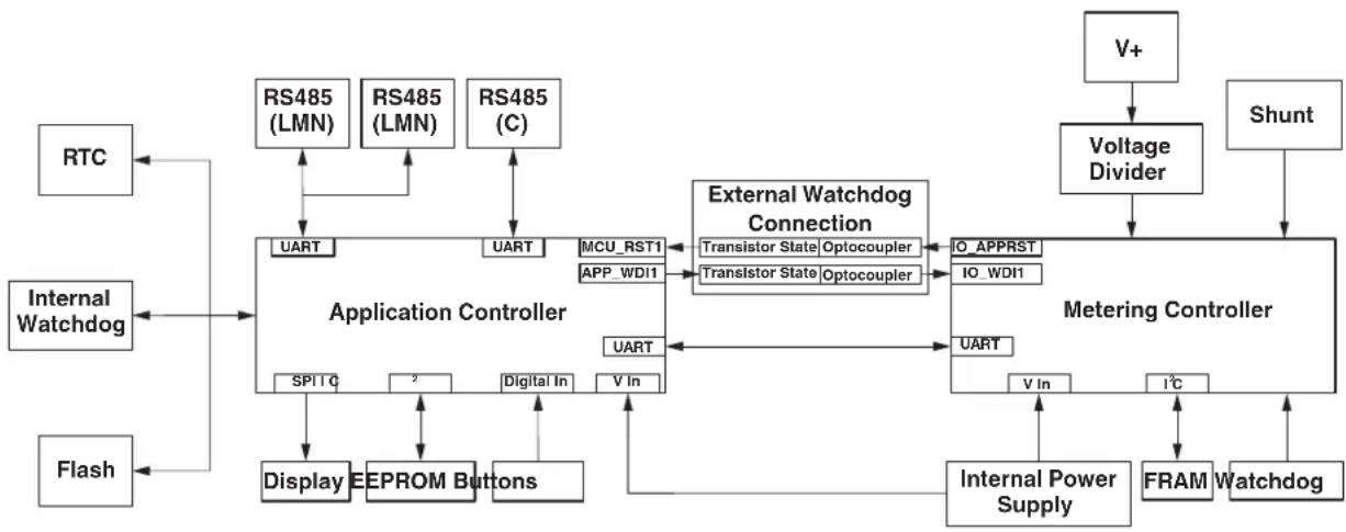
The DC energy meter consists of two independent components: the metering part and the application part. Both parts communicate via a non-reactive serial interface.
Figure 2-7 Simplified block diagram of the DC energy meter
flowchart
graph TD
    A["RTC"] --> B["Application Controller"]
    C["Internal Watchdog"] --> B
    D["Flash"] --> B
    B --> E["Display EEPROM Buttons"]
    B --> F["SPITQ"]
    B --> G["MCU_RST1"]
    B --> H["APP_WDI1"]
    B --> I["Digital In"]
    B --> J["V In"]
    B --> K["External Watchdog Connection"]
    K --> L["Transistor State Optocoupler"]
    K --> M["Transistor State Optocoupler"]
    N["V+"] --> O["Voltage Divider"]
    P["Shunt"] --> Q["Metering Controller"]
    R["V In"] --> S["Internal Power Supply"]
    T["I²C"] --> U["FRAM Watchdog"]
    V["RS485 (LMN)"] --> B
    W["RS485 (LMN)"] --> B
    X["RS485 (C)"] --> B
    Y["RFAM"] --> Z["Watchdog"]
The voltage sampling is implemented by a resistor divider network. Current sampling is implemented by a 20 manganin shunt. The DC voltage is filtered by a RC-network. The metering chip (V9911) integrates the voltage and current measurement in a SoC, to obtain power and other instantaneous values. Power and energy values are computed and stored inside the metering part.
The application part is designed to control the local user interface – the buttons and the dot-matrix display – as well as the two serial communication interfaces. The RTC is integrated in the application part, the storage of charging session data and Eichlog is controlled by the application controller.
3 Quick-start guide
– Download the PHOENIX CONTACT DC-METER VIEW in the Downloads of the product page and start this software.
- Connect the adapter EEM-RS485-PCM (item no.1551889) to a USB port of your computer and the RJ12-3 port of the DC energy meter.
- Select the serial port at the settings of the PHOENIX CONTACT DC-METER VIEW with Baudrate 115200, Data bits 8, and Parity None and push the "Connect" button within the software.
After start, the DC energy meter will go through the following states: selftest, info, public key and end up in operation state.
First steps: configuration of a single DC energy meter
From the tab list, select "CONFIGURATIONS"
The available configurable options are:

DC energy meter is in normal mode at the time of delivery. The change between normal and assembly mode can be done by pressing the button "SET NORMAL MODE" or "SET ASSEMBLY MODE".
Normal Mode
SET TIME: synchronizes times to the computer
GET TIME: reads out the time
SET ADDRESS: sets the bus address (0 ... 255)
Assembly Mode
SET LINE IMPEDANCE: stores impedance for line loss energy calculation (0 ... 0,1)
SET CHARGE POINT IDENTIFICATION: Type and ID of charge point
WRITE LINE LOSS ENERGY MEASUREMENT MODE: Line Loss Measurement Mode 2 (LLMM2 by impedance)
Configuration of multiple DC energy meter
You can download and upload application and assembling configurations to transfer settings in between several DC energy meters.
Further information about the usage of the DC energy meter can be found in the following sections:
– Section "Mounting and installation" on page 17
– Section "Configuration" on page 21
– Section "Operation" on page 25
4 Mounting and installation

DANGER: High voltage and/or current
It is always mandatory to ensure that the maximum peak voltage and maximum peak current of the desired application do not exceed the maximum peak values of the DC energy meter. Otherwise the DC energy meter will be damaged due to overvoltage and/or overcurrent. These peak values are 1000 V DC (maximum voltage), +3102 V overvoltage margin and 650 A (maximum current) and 15 kA overcurrent margin.
The DC energy meter can be used as a stand-alone meter without any additional equipment. This ensures a full range of functions with a compact design.
Overvoltage protection
The isolated DC EV (electric vehicle) charging station must reduce overvoltage to the DC energy meter and the EV to the rated impulse voltage of 2.5 kV.
Requirements for charging station and controller
The public key and the server ID of the DC energy meter have to be attached to the charging station so that it is visible from the outside for each charging point.
Requirements for transparency software
Transparency software (download from a trustful resource) must be used to display the invoiced data in compliance with the legal requirements, which enables signature verification of the measurement data records for invoice control.
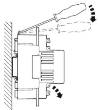
4.1 Snapping the device onto the DIN rail
The device is snapped onto a DIN rail in the control cabinet. The mounting position can be freely selected, but will be determined by the readability of the LCD.
Figure 4-1 Snap on DIN rail schematic
natural_image
Technical line drawing of a mechanical assembly with a screwdriver and directional arrows indicating motion (no text or symbols)4.2 Installation

DANGER: Unforeseen consequences of poor installation
The DC energy meter and all associated components may only be installed in compliance with all safety regulations. Ignoring these instructions may endanger life and the manufacturer will not take any responsibility.

The manufacturer is not responsible for any damage caused by disregard of the instructions.
The DC energy meter must be installed in a dry well-ventilated area, on a top-hat rail and away from flammable or vibrating components. Protect the DC energy meter against possible damage by enclosures or protective caps. During installation, the proper operation of the DC energy meter must be ensured. The wiring must be carried out according to Figure 4-2.
Wiring procedure:
- Connect the current power lines to the shunt of the DC energy meter using M8 or M10 nut screws. (17.5 Nm ... 20 Nm — prevents damage or corrosion).
- Connect the voltage terminal 1 (V+) with a 0.75 mm ^-2 ... 1.5 mm ^2 cross section cable (0.5 Nm ... 0.6 Nm).
- Connect the power supply terminals 16 (+) and 17 (-) with a 0.75 mm ^2 ... 1.5 mm ^2 cross section cable (0.5 Nm ... 0.6 Nm).
- Connect the communication interface of DC charging controller at RJ12-1.

To build up a daisy-chained network with several DC energy meters and a DC charging controller, please establish a communication link between DC energy meters via RJ12-1 and RJ12-2 interfaces.

After installation of the DC energy meter, it is mandatory to change the operating status from assembly mode to operation mode.
Figure 4-2 Connections of the DC energy meter
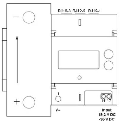
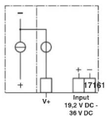
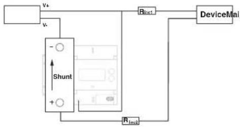
Figure 4-3 Wiring of the DC energy meter
flowchart
graph TD
    A["Shunt"] --> B["V+"]
    A --> C["V-"]
    B --> D["DeviceMai"]
    C --> D
    D --> E["Rin1"]
    E --> F["DeviceMai"]
    G["Rin2"] --> D
4.3 Cover and seal
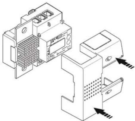
Any interface manipulation during the operation is prevented by a sealed cover.

The seals for the cover are not within the scope of supply.
Figure 4-4 Cover of the DC energy meter
natural_image
Technical line drawing of two electronic device modules with internal components and directional arrows indicating assembly or connection (no text or symbols present)Figure 4-5 Security seal of the DC energy meter with safety punching
natural_image
Pure electrical circuit symbol for a diode (no text or labels)5 Configuration
To provide a better usability and customizability, the DC energy meter offers some configurable options for the operator. This option can be configured within the application and the assembly configuration. The production configuration can only be written during production. For simplicity, only the application and the assembly configuration are subject of this section. The following both sections describe both configuration sets regarding their possible settings and their default preset.
5.1 Application configuration
The first part of the application configuration contains all settings for both serial interfaces. Every block is separated with ",".
Serial interfaces
"DC meter view" interface (RJ12-3) DC charging controller (RJ12-1 and RJ12-2)
Baudrate (default value: 115200) Baudrate (default value: 19200)
Data bits (default value: 8) Data bits (default value: 8)
Parity (default value: 0 [none]) Parity (default value: 0 [none])
Stop bits (default value: 1) Stop bits (default value: 1)
Application configuration — display
The second part of the application configuration contains all configurations regarding the internal display content. That means, which OBIS numbers are visible in which line (upper/lower line) in which state (operation, charging, charging summary). The time between each item of the states is 6 s (6000 ms).
Operation
Upper line Registers
- none (default, not editable)
Lower line Registers
- OBIS phase L1 Current,
- OBIS phase L1 voltage,
- OBIS total import mains power,
- OBIS local device time
Charging
Upper line Registers
– OBIS total transaction import line loss energy
Lower line Registers
- OBIS total import mains power,
- OBIS import device power
- OBIS import line loss power
- OBIS local device time
- OBIS public key
– OBIS total transaction charge duration
Charging summary
Upper line Registers
– OBIS total transaction import line loss energy
Lower line Registers
- OBIS local device time
- OBIS total transaction charge duration
- OBIS public key
Display properties
The last part of the display configuration contains the configurable properties of the display.
Backlight configuration 0: backlight permanently off
1: backlight always on
2: backlight on during charging session
3: backlight on after button interaction (default)
4: on by charge or button press
Backlight button press 5000 (5 s) (default) timeout:
Show public key True
False
(Currently without effect, can be shown on display by OBIS 1-0:94.49.0*2, see Table 6-4 on page 29 for details)
Application configuration — charging and feature
The third part of the application configuration contains the charging configuration, feature configuration, and the exploration configuration with the following entries:
Charging configuration
In this part the bus address of the DC energy meter is set. The value can vary between 0 ... 255 (0x00 ... 0xFF).
5.2 Assembly configuration
Calibration law control
Use external display True
False
Additional external
Registers visible (external display in use)
display registers
No registers (no external display in use)
OCMF configuration – AdditionalRegistersStart
- AdditionalRegistersStop
- AdditionalRegistersVendorSpecificStart
- AdditionalRegistersVendorSpecificStop
(Each is a list with the length of four corresponding to:
ContentTemplate1, ContentTemplate2,
ContentTemplate3 or ContentTemplate4.)
Metrology
Line loss energy measurement mode 2 (by impedance)
6 Operation
6.1 Device statuses
The DC energy meter operates within three operating statuses that allow the user different access rights to the DC energy meter. These three statuses are production mode, assembly mode, and operation mode. A change of the operating mode is always accompanied by an entry in the calibration law relevant Eichlog.
The production mode is only active during the production of the DC energy meter. Full access to the DC energy meter is possible within this mode.
Alterable DC energy meter settings within the production mode
All registers shown in Section "Charging session" on page 52 can be written.
Transition conditions
The production mode can be reached by sending the corresponding control command via one of the serial interfaces of the DC energy meter, only if an additional hardware jumper within the housing of the DC energy meter is set.
6.1.2 Assembly mode
The assembly mode is intended exclusively for customers who install the DC energy meter in an existing product and resell it to the end user in the assembly mode. Within the assembly mode, the user is granted further access rights to alter settings of the DC energy meter. This makes it possible to adapt billing-relevant settings to the corresponding conditions of the installation location.
Alterable DC energy meter settings within assembly mode
Within the assembly mode, the access rights already available from the operation mode are extended by the following billing-relevant setting options:
- Setting of line loss impedance. Only values up to a maximum of 0.1 are allowed for the line loss impedance.
- Setting of charge point identification.
Transition conditions
The assembly mode can be reached without further physical intervention of the user by sending the corresponding control command via one of the serial interfaces of the DC energy meter.
A list of all possible control commands is given in Section "Registers" on page 47.

To ensure data integrity, it is not possible to switch to the assembly mode during a charging session.
6.1.3 Operation mode
The DC energy meter is shipped in operation mode. Within this mode, the access to the DC energy meter registers is according to the Table 7-1 on page 47. This means that all billing-relevant data can be read but not altered.
Alterable DC energy meter settings within operation mode
This operation mode only allows alterations to settings of the DC energy meter that are not relevant for billing. This is a software safety measure to ensure complete data integrity. The following values can be changed within the operation mode:
- Setting and or alteration of the device bus address.
- Setting of the information time of the DC energy meter. An alteration of this value is only allowed, if currently no charging session is ongoing.
- Setting of informative displayable DC energy meter values.

Charging is only permitted in this operation mode.
Transition conditions
The operation mode can be entered at any time without any additional physical intervention by sending the corresponding control command via one of the serial interfaces of the DC energy meter.
A list of all command sets can be found in Section "Device information" on page 47.
6.2 Internal display state machine
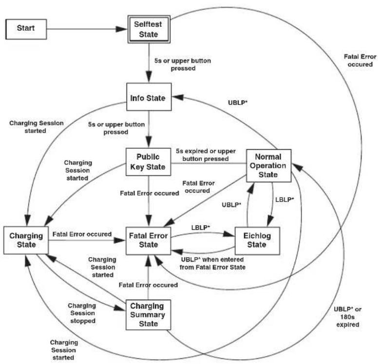
The control of the internal display consists of a state machine that changes the current display state according to the present measurement data. Figure 6-1 shows the complete display state machine with all transitions and their corresponding conditions. The contrast voltage may be configured. All button actions activate the backlight for the configured time period, which is set to 5 s by default.
Figure 6-1 Schematic illustration of the internal display state machine
flowchart
graph TD
    Start --> Selftest State
    Selftest State -->|5s or upper button pressed| Info State
    Info State -->|Charging Session started| Charging State
    Info State -->|5s or upper button pressed| Public Key State
    Public Key State -->|Charging Session started| Charging State
    Public Key State -->|Fatal Error occurred| Fatal Error State
    Public Key State -->|Fatal Error occurred| Normal Operation State
    Normal Operation State -->|UBLP*| Eichlog State
    Normal Operation State -->|LBLP*| Eichlog State
    Eichlog State -->|UBLP* when entered from Fatal Error State| Fatal Error State
    Eichlog State -->|LBLP*| Fatal Error State
    Eichlog State -->|Charging Session stopped| Charging Summary State
    Eichlog State -->|Charging Session started| Charging Summary State
    Eichlog State -->|Charging Session occurred| Fatal Error State
    Eichlog State -->|Charging Session stopped| Fatal Error State
    Eichlog State -->|Charging Session started| Fatal Error State
    Eichlog State -->|Charging Session stopped| Fatal Error State
    Ferial Error Occurred --> Fatal Error State
    Fatal Error Occurred --> Normal Operation State
    Fatal Error Occurred --> Eichlog State
    Fatal Error Occurred --> Eichlog State
    Fatal Error Occurred --> Charging Summary State
    Fatal Error Occurred --> Charging Session Started
    Fatal Error Occurred --> Charging Session Stopped
    Fatal Error Occurred --> Fatal Error State
    Fatal Error Occurred --> Fatal Error State
    Fatal Error Occurred --> UBLP* or 180s expired
    Fatal Error Occurred --> UBLP* or UBLP* occurred
* legend for button action acronyms
UBLP: "Upper button long pressed"
LBLP: "Lower button long pressed"
6.2.1 Selftest state
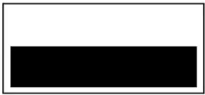
In the display selftest state, the DC energy meter performs a test sequence on the display to ensure that all pixels are fully functional. During this test sequence, a black bar is shown alternately at the lower and upper half of the screen, as exemplified in Figure 6-2. The bar is visible for 1 s. The change between the lower and upper half of the display state out 3 times. The total duration of this state is therefore about 7 s. To facilitate the detection of faulty pixels during this display test, the backlight is continuously active.
Figure 6-2 Display — selftest state
natural_image
Simple black rectangle centered on white background (no text or symbols)This state transmits directly to the display info state without further intervention. The test can be skipped by pressing the upper button in order to enter the display info state immediately.
Table 6-1 Display — selftest state transitions
| State transition | ||||
| Selftest → After 5 s automatically → Info | ||||
| Selftest → “Upper button short press” → Info | ||||
6.2.2 Info state
Within the display info state, the checksums and version numbers of the application and the metering firmware are displayed, as shown in Figure 6-3.
Figure 6-3 Display — info state
| EEM-PM157-SLP | |
| 94.100.1 | 1 DZG0 21080003 |
| 1-0:0.2.0.1 | 231 |
| 1-096.90.2.1 | 6b30 |
| 1-0:0.2.0.2 | V1.22 |
| 1-0:96.90.2.2 | 3a23 |
Type designation of the DC energy meter
Server ID of the DC energy meter
Application firmware version
Application firmware checksum
Metering firmware version
Metering firmware checksum
Table 6-2 Display — info state transitions
| State transition | ||||
| Info → After 5 s automatically → Public key | ||||
| Info → “Upper button short press” → Public key | ||||
| Info → When charging session starts → Charging | ||||
6.2.3 Public key state
Table 6-3 Display — public key state transitions
| State transition | |||
| Public key → After 5 s automatically → Operation | |||
| Public key → “Upper button short press” → Operation | |||
| Public key → When charging session starts → Charging | |||
6.2.4 Operation state
During the operation state, all measurement readings and general information of the DC energy meter are displayed as shown in Figure 6-4. The values to be displayed are rotated according to a configured interval. All values relevant to German calibration law (Eichrecht) are displayed in the upper line and all informative values in the lower line.
Figure 6-4 Display — state operation
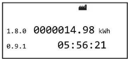
The standard setting for the rotation interval of the display values is 5 s. Table 6-4 shows all displayed values, including their relevance. The listed registers are written to the DC energy meter during production. The registers in the bottom line (informative registers) can be altered by the customer at any time. This is not possible for the registers of the upper line, which are used for billing purposes.
Table 6-4 Display information in states: operation, charging, and charging summary
| Upper line content (billing relevant) | ||
| OBIS code Name | Relevant | for billing |
| 1-0:1.8.0*255 | Total import mains energy | Yes |
| 1-0:140.7.0*255 | Line loss impedance | Yes |
| 1-0:152.8.0*255 | Total transaction import device energy Yes | |
| Lower line content (informative) | ||
| 1-0:32.7.0*255 | Phase L1 voltage | No (informative) |
| 1-0:31.7.0*255 | Phase L1 current | No (informative) |
| 1-0:16.7.0*255 | Total mains power | No (informative) |
| 1-0:156.7.0*255 | Import device power | No (informative) |
| 1-0:0.9.1*255 | Device time | No (informative) |
| 1-0:0.9.2*255 | Device date | No (informative) |
Table 6-4 Display information in states: operation, charging, and charging summary [...]
| Upper line content (billing relevant) | ||
| 1-0:154.8.0*255 Total | import line loss energy No (informative) | |
| 1-0:156.8.0*255 Total | import device energy No (informative) | |
| 1-0:94.49.0*2 Public key | No (informative) | |
OCMF display
Table 6-5 OCMF display information in states: operation, charging, and charging summary
| OCMF content (informative) | |
| OBIS code Name | |
| 1-1:98.128.0*255 FV (format version) | |
| 1-1:98.128.1*255 GI (gateway identification) | |
| 1-1:98.128.2*255 GS (gateway serial) | |
| 1-1:98.128.3*255 GV (gateway version) | |
| 1-1:98.128.8*255 PG (pagination) | |
| 1-1:98.128.16*255 MV (meter vendor) | |
| 1-1:98.128.17*255 MM (meter model) | |
| 1-1:98.128.18*255 MS (meter serial) | |
| 1-1:98.128.19*255 MF (meter firmware) | |
| 1-1:98.128.24*255 IS (identification status)** | |
| 1-1:98.128.27*255 IT (identification type)** | |
| 1-1:98.128.28*255 ID (identification data)** | |
| 1-1:98.128.32*255 CT (charge point identification type) | |
| 1-1:98.128.33*255 CI (charge point identification) | |
** available after first charging session after power cycle.
The general information of the DC energy meter is displayed with symbols in the upper part of the screen. An explanation of the displayed symbols can be found in Table 2-4 on page 11.
Table 6-6 Display — operation state transitions
| State transition | |||
| Operation → “Upper button short press” → Show next DC energy meter value | |||
| Operation → “Upper button long press” → Selftest state | |||
| Operation → “Lower button short press” → Show previous DC energy meter value | |||
| Operation → “Lower button long press” → Eichlog state | |||
| Operation → When charging session starts → Charging |
6.2.5 Charging state
Within the charging state, all DC energy meter values relevant for billing and calibration law are shown on the display as illustrated in Figure 6-5. The same system used for the operation mode is used here as well, which means that the values rotate by time period displayed in the two lower lines. Analogous to the operation mode, all DC energy meter values relevant for calibration law, and therefore important for billing, are displayed in the upper line and all informative values in the lower line. To distinguish the display operation state from the display charging state, "Charging" is displayed in the left half of the headline block. All other shown symbols are described in more detail in Table 2-4 on page 11.
Figure 6-5 Display — charging state
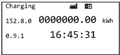
The standard setting for the rotation period of the display values is 5 s. Table 6-4 on page 29 shows all displayed values, including their relevance. The listed registers are written to the DC energy meter during production. The registers in the bottom line (informative registers) can be altered by the customer at any time. This is not possible for the registers of the upper line, which are used for billing purposes.
The display information of this state is shown in Table 6-4 on page 29.
The OCMF display information of this state is shown in Table 6-5 on page 30.
Table 6-7 Display — charging state transitions
| State transition | |||
| Charging → | “Upper button short press” → Show | next DC energy meter value | |
| Charging → | “Lower button short press” → Show | previous DC energy meter value | |
| Charging → | When charging session stops → Charging summary | ||
6.2.6 Charging summary state
The display charging summary state is basically a summary of the charging session that has just been carried out. All DC energy meter values necessary for a complete billing procedure should be shown to the customer as shown in Figure 6-6. Analogous to the display operation state or the display charging state, all values are also displayed in rotation. All billing relevant values are shown in the upper line of the display whereas all informative values are displayed in the lower line (highlighted in yellow). To ensure better differentiation within this state, "Summary" is displayed in the left half of the headline block (marked red), analogous to the charging state. All other symbols are described in Table 2-4 on page 11 in more detail.
Figure 6-6 Display — charging summary state
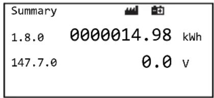
The rotation period of the displayed values is set to 10 s by default (18 rotations). This value cannot be altered by any means. Table 6-4 on page 29 shows all displayed values, including their relevance. The listed registers are written to the DC energy meter during production, where the registers in the bottom line (informative registers) can be altered by the customer at any time. This is not possible for the registers of the upper line, which are used for billing purposes.
The display information of this state is shown in Table 6-4 on page 29.
The OCMF display information of this state is shown in Table 6-5 on page 30.
Table 6-8 Display — charging summary state transitions
| State transition | ||||
| Charging summary → “ | Upper | button short press” → Show next value | ||
| Charging summary → “ | Lower | button short press” → Show previous value | ||
| Charging summary → “ | Upper | button long press” → Operation | ||
6.2.7 Eichlog state
The display Eichlog state is a list of all entries that are stored within the calibration law relevant logbook (Eichlog). The values of the entry, its timestamp, and its local time offset are displayed as illustrated in Figure 6-7. Displaying the entries does not influence the underlying Eichlog. The selection of the entry to be displayed is made exclusively by pressing the DC energy meter buttons. It is not possible to switch back or forward independently of the user. The sequence of the displayed entries is identical to that in the Eichlog. The display Eichlog state is available at application firmware version v228.
Figure 6-7 Display — Eichlog state
Eichlog (1, 771354)
Time Delta too big
2020-12-18T10:16:29+0100
Old: 11:16:29
New: 11:49:18
Table 6-9 Display information — Eichlog state
| Line Informative content |
| 1 Eichlog (number of the entry in the logbook, internal timestamp) |
| 2 Type of the entry |
| 3 Informative timestamp |
| 4 Value before the entry creating stamp |
| 5 Value after the entry creating stamp |
If a fatal error occurs within this state, the display as well as the entire DC energy meter will enter the meter fatal error state. It is possible, to switch back to this state again by long pressing the lower button, which changes only the display state and not the DC energy meter state. Once a fatal error is detected, the DC energy meter remains in its meter fatal error state. The possibility to change the display state allows the user a better debugging experience.
By pressing the upper button for a long time, you can leave the display Eichlog state and change to the display operation state. If the Eichlog state was entered from the meter fatal error state, the display also returns to this state by pressing and holding the upper button. If none of the above conditions occur the display remains in this state.
Table 6-10 Display — Eichlog state transitions
| State transition | ||||
| Eichlog → | “Upper button short press” → Show next Eichlog entry | |||
| Eichlog → | “Lower button short press” → Show previous Eichlog entry | |||
| Eichlog → | “Upper button long press” → Operation | |||
6.2.8 Eichlog memory full
In case the Eichlog is full an informational message "Logbook full" message is shown on the display. This is illustrated on Figure 6-8 (marked red). In addition no charging session can be started anymore.

The Eichlog cannot be reset. To run more charging sessions, a new device is required.
Figure 6-8 Display — Eichlog memory full
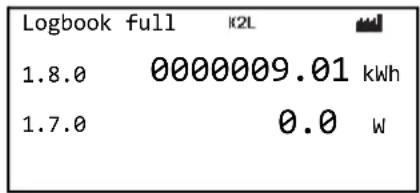
6.2.9 Fatal error state
If a fatal error occurs during operation, the DC energy meter and the display change to the meter fatal error state as illustrated in Figure 6-9. The DC energy meter remains in this state for the rest of its operating time. Within this state, the DC energy meter shows its general billing relevant values rotating in the top value line. The corresponding status word of the DC energy meter is now permanently shown in the bottom value line. Once the DC energy meter is in this state, no charging session can be started. If a fatal failure is detected, the DC energy meter must be exchanged by an authorized person. To clearly distinguish the meter fatal error state from the other states, "Fatal Failure" is displayed in the left half of the headline block.
Figure 6-9 Display — fatal error state
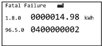
The values displayed in the upper line are based on the register values of the display operation state, which are listed at Table 6-11. The contents of the lower display line are omitted.
Table 6-11 Display information — fatal error state
| Upper line content (billing relevant) | |
| OBIS Description Billing relevance | |
| 1-0:1.8.0*255 Total import mains energy Yes | |
| 1-0:140.7.0*255 Line loss impedance Yes | |
| 1-0:152.8.0*255 Total transaction import device energy Yes | |
As already mentioned, the DC energy meter fatal error state cannot be left once it has been entered. By pressing the lower button for a long time, it is possible to switch to the Eichlog state for further debugging purposes, but this leads back to the DC energy meter fatal error state.
Table 6-12 Display — fatal error state transitions
| State transition | ||||
| Fatal error → “Upper button short press” → Show next DC energy meter value | ||||
| Fatal error → “Lower button short press” → Show previous DC energy meter value | ||||
| Fatal error → “Lower button long press” → Eichlog | ||||
6.3 Line loss energy calculation
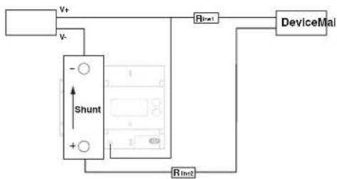
The DC energy meter can calculate the line loss energy. For that reason, the impedance ( R_line ) must be configured. The impedance can only be changed in the assembly mode. The Eichlog records any change of the impedance.
The metering controller calculates the line loss power and its resulting energy. The line loss registers count the line loss energy. If the impedance is set to zero (0), the line loss measurement is deactivated, the corresponding status flag is deleted, and the display symbol is switched off.
Figure 6-10 Wiring of the DC energy meter
flowchart
graph TD
    A["Shunt"] --> B["V+"]
    A --> C["V-"]
    D["DeviceMai"] --> E["Rin1"]
    A --> F["Rin2"]
    A --> G["Rin3"]
As shown in Figure 6-10, the overall line loss impedance is a result of the impedance of the wire between the positive terminal of the mains supply and the device itself R me1 and of the impedance of the wire between the second terminal of the device to the positive terminal of the DC energy meter shunt R me2 . Therefore, the overall line loss impedance can be calculated as sum of both wire impedances.
The calculation is described with the following:
Line loss impedance R lineloss = R_line1 + R_line2
In this document the line loss impedance is mentioned several times. This refers to the overall line loss impedance. The same applies for the configurable line loss impedance. In the two-wire line loss measurement mode (K2L), the line loss energy is calculated as:
Line loss power (LLP) P llp(t)=Ishunt^2× R_line
Line loss energy _0^t P_LineLoss(t) dt
The value for l_shunt refreshes with a maximal period of 1500 ms. The same value is applied for the integration constant for the line loss energy. The energy integration cycle is synchronized with the line loss power cycle.
6.4 Energy flow
For import energy mode, the register values for every point in time are given by:
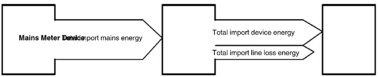
Total import mains energy = Total import device energy + Total import line loss energy with R_line = (R_line1 + R_line2) > 0 , which is illustrated in Figure 6-11.
The exact calculation is given by:
Total import mains power (IM) P_im(t) = I_shunt(t) × U_terminal(t)
Total import device power (ID) P_id(t) = P_im(t) - P_llp(t)
Total import mains energy _0^tP_im(t)dt
Total import device energy _0^tP_ia(t)dt
The refreshment cycle of the base values for the respective power calculation and integration cycle of the resulting energy are synchronized.
Figure 6-11 DC energy meter energy flow import
Import
flowchart
graph LR
    A["Mains Meter Device"] --> B["Device import mains energy"]
    B --> C["Total import device energy"]
    B --> D["Total import line loss energy"]
6.5 Charging session
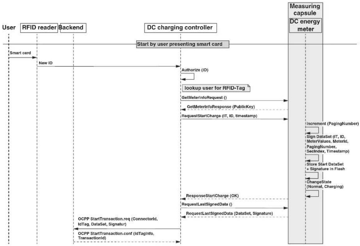
This section describes the charging session by an example of authenticating a user by a smart card. Before the start of a charging session, the current user is authorized by the charge station controller via the UID of the smart card (for example, RFID).
When a charging session starts, the DC charging controller uses the request start charge command to write the user data (ID, IT, see OCMF [7]) and the system local timestamp to the DC energy meter. The DC energy meter assembles a data set, containing user data, timestamp, meter readings (mandatory energy registers, status word), and charge station controller-identification. This data set is hashed (SHA256) and signed by a secp256k1 signature. The DC charging controller can retrieve the signed data set in OCMF format. The output is compliant to OCMF 1.0 and can be used as an input for the transparency software. The content of the mandatory registers for OCMF and display can be configured in production and assembly mode. The timestamp of the OCMF data set is informative.
Start
A charging session can only be started when all the following conditions are met:
- Status word indicates no error
- Time delta of the internal RTC time and the current time is less than 300 s.
– Capacity of the Eichlog and the charging session storage is not exhausted.
The signed charging session data can be requested in OCMF format after start.
Figure 6-12 Example of a charging session initiated by a user presenting a smart card
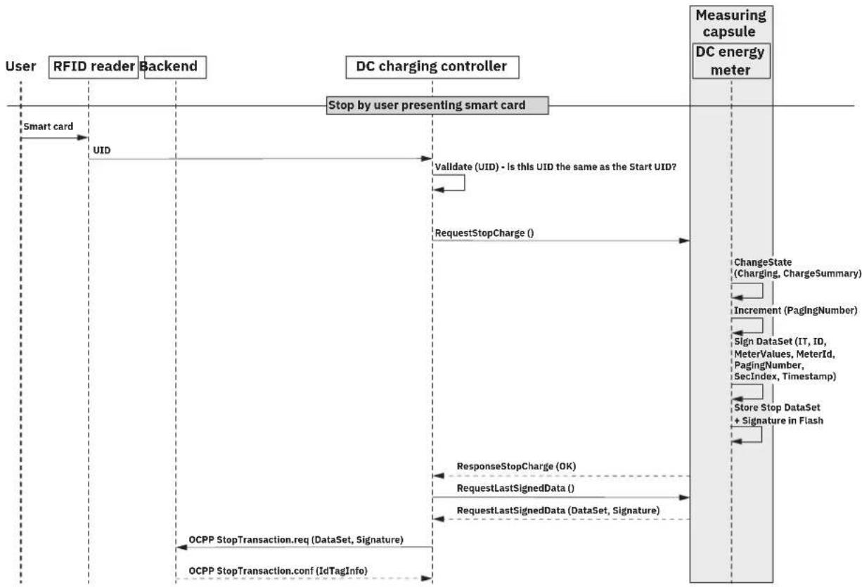
A charging session can only be stopped if the status word indicates no error and if the capacity of the Eichlog and the charging session storage is not exhausted.
After stopping a charging session, the signed charging session data can be requested in OCMF format.
The stop charging session reading includes the Start-, Stop-, and delta readings of the charging session. The OCMF content can be configured in assembly mode to include mains, device, and loss energy. The device energy is a mandatory register.
Figure 6-13 Example of a charging session initiated by a user presenting a smart card
flowchart
graph TD
    A["User"] -->|Smart card| B["RFID reader"]
    B -->|UID| C["Backend"]
    C --> D["DC charging controller"]
    D --> E["Stop by user presenting smart card"]
    E --> F["Measuring capsule"]
    F --> G["DC energy meter"]
    G --> H["ChangeState (Charging, ChargeSummary)"]
    H --> I["Increment (PagingNumber)"]
    I --> J["Sign DataSet (IT, ID, MeterValues, MeterId, PagingNumber, SecIndex, Timestamp)"]
    J --> K["Store Stop DataSet + Signature in Flash"]
    K --> L["RequestStopCharge (OK)"]
    L --> M["RequestLastSignedData ( )"]
    M --> N["RequestLastSignedData (DataSet, Signature)"]
    N --> O["OCPP StopTransaction.req (DataSet, Signature)"]
    O --> P["OCPP StopTransaction.conf (IdTagInfo)"]
    P --> Q["OCPP StopTransaction.req (DataSet, Signature)"]
    Q --> R["Validate (UID) - Is this UID the same as the Start UID?"]
    R --> S["RequestStopCharge ( )"]
Stop after power failure
If the DC energy meter experiences a power failure while a charging session is ongoing, the DC energy meter will not go back into the charging mode by itself but will set the status session not completed bit within the status word.
While this bit is set, it is possible to start a new charging session, by sending the regular start charge command as explained above. In this case, the aborted charging session has no further effect. Another option is to send the regular stop charge command, as explained above. This will restore the pending charging session readings and immediately stop the
session. Within the OCMF output of this charging session, the stop meter readings will have the status "A", for a canceled charging session. In any case each start data tuple is stored in the internal memory and is uniquely identifiable by its paging number.
Charging session storage
All charging sessions are recorded in the internal storage. The historic processes can be read securely (signed) via the communication interface. The secured communication is realized with the TLS library version 2.6.1 of mbed. Entries are never overridden. Charging sessions can only be started if there is capacity in the storage.
The capacity of the charging session storage is dimensioned for a lifetime of 12 years (25 charging sessions per day). The individual charging session records are stored with a unique strictly monotonically increasing identification number (pagination).
A check at the beginning of each charging session ensures that there is at least enough space for one more charging session (start and stop entry) in the storage left.
In case of an error during a charging session, no billing relevant dataset is generated.
6.6 Clock
The time is represented as local time. If the drift of the internal RTC is too big (5 min), the corresponding event and its related values are traced in the Eichlog.
The following rules apply:
- If a time is set with a delta greater than 300 s, no charging session may be started for 60 s.
- If the time delta is greater than 300 s on starting a charging session, the command will be rejected and the time will be set. Previous rules apply.
– The time can only be set every 60 s.
– During an ongoing charging session, setting the time is not allowed.
6.7 Eichlog
An Eichlog is implemented, that records every event that can influence the metrological readings. The Eichlog can be accessed via the communication interface. The communication is secured by the usage of ECDSA signatures. The authentication is provided by including the device identification into the signed responses. The Eichlog is safely and chronologically stored in the internal storage of the DC energy meter. The Eichlog cannot be overridden. If the capacity is exhausted, no further charging sessions are allowed. Therefore, the DC energy meter must be changed by an authorized person.
Table 6-13 describes the overall structure of an Eichlog entry and Table 7-25 on page 58 describes all available events that cause a new Eichlog entry. The Eichlog can be accessed via the display of the DC energy meter.
Table 6-13 Structure of an Eichlog entry
| Size in byte Description Value type | ||
| 1 Eichlog type enum | ||
| 4 Second index uint32_t | ||
| 4 UTC time uint32_t | ||
| 1 Local time offset int8_t | ||
| N Old value Depends on type | ||
| N New value Depends on type | ||
| 10 | Server ID | byte [10] |
| 64 | Signature | byte [64] |
6.8 External display
An external display can be connected via the communication ports. The communication is secured by a secp256k1 elliptic curve signature. If the external display option is enabled, a charging session can only be started, if the display is connected and functional. Therefore, certain timing requirements must be met. The display must respond to periodic watchdog requests. A deviation from this timing indicates a malfunction of the display and is tracked in the Eichlog as well as in the status word.
7 Technical data
7.1 Product specification
Type EEM-PM157-SLP
| Voltage | |
| U_min | 150 V |
| U_max | 1000 V |
| Screw connection stranded / AWG 0.75 mm ^2 ... 1.5 mm ^2 / 16 ... 20 | |
| Tightening torque 0.5 Nm ... 0.6 Nm | |
| Current | |
| Starting current I_st | 0.52 A |
| Minimum current I_min | 6.5 A |
| Current I_tr | 13 A |
| Normal current I_Ref | 130 A |
| Maximum current I_max | 650 A |
| Nut connection M8 or M10 | |
| Tightening torque 17.5 Nm ... 20 Nm | |
| Accuracy | |
| Class Class B | |
| Measuring active energy | |
| One energy direction +A with -A locking | |
| Energy register | |
| Total mains and device energy +A | |
| Meter constant | |
| LED-Output 1000 I _mp /kWh, total mains energy | |
| Display | |
| LCD | Dot-Matrix display with 7.2 digits |
| Life cycle | >12 years |
| External display (option) | |
| Communication port | All RJ12 ports |
| RS-485- data interface 1 and 2 | |
| Connector | RJ12 ports |
| Parameter | 19200 bps, 8N1 (settable) |
| RS-485- data interface 3 | |
| Connector | RJ12 port |
| Parameter | 115200 bps, 8N1 (settable) |
| Power consumption | |
| Supply voltage range | 19.2 V DC ... 36 V DC |
| Voltage circuit | < 0.5 W at U_n |
| Current circuit | < 0.12 W at I_max |
| Auxiliary power supply | < 5 W |
Temperature range
| Typical operation -40 °C ... +80 °C | |
| Storage -40 °C ... +85 °C | |
| Humidity | |
| max. 97.5 %, not condensingEN 60068-2-30:1999 | |
| Environmental conditions | |
| Mechanical environmental conditions M1 | |
| Electromagnetic environmental conditions E2 | |
| Housing | |
| Mounting DIN-Rail | |
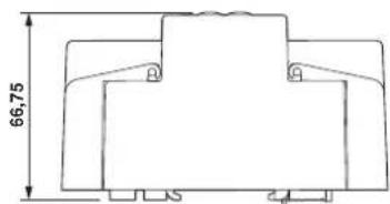
| Dimensions | 115.6 mm (H) x 107.2 mm (W) x 66.75 mm (L) |
| Material Fiber-glass reinforced polycarbonate | |
| Storage | |
| Capacity for start- and stop-charge records | >225000 |
| Capacity of Eichlog >2500 | |
| Metering firmware | |
| Version V1.22 | |
| Checksum 3A23 | |
| Application firmware | |
| Version V232 | |
| Checksum 442C | |
| Hash | E2DCB0177923A2C5724FF88EC56FB56D7407106B329A92CA699362E6311D0E88 |
7.2 Dimensions
The DC energy meter is constructed to be mounted on a DIN-rail NS 35-7.5 (part no. 0801733), in accordance with IEC 60715.
Figure 7-1 Dimensioned front view of the housing (unit: (mm))
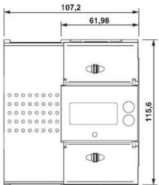
Figure 7-2 Dimensioned bottom view of the housing (unit: (mm))
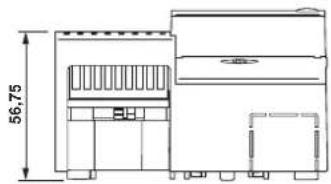
Figure 7-3 Dimensioned side view of the housing (unit: (mm))
7.3 Applicable technical standards
[1] EN 50470-1 Electricity metering equipment (a.c.) - part 1: General requirements, tests, and test conditions - metering equipment (class indexes A, B, and C); revision date: May 2007
[2] EN 50470-3 Electricity metering equipment (a.c.) - part 3: Particular requirements - static meters for active energy (class indexes A, B, and C); revision date: June 2007
[3] IEC 62052-41 Electricity metering equipment (AC) – general requirements, tests and test conditions, revision date: February 2003
[4] DIN EN 62052-11 Electricity metering equipment (AC) - general requirements, tests, and test conditions - part 11: Metering equipment; revision date: November 2003
[5] VDE-AR-E 2418-3-100 Measuring systems for charging stations, revision date: August 2019
[6] EN 62053-41 Electrical energy measurement and control, revision date: April 2020
[7] OCMF 1.0 Open charge metering format, revision date: February 2019
[8] PTB - A 20.1 Measuring devices for electricity: electricity meters and their auxiliary equipment, revision date: December 2003
[9] PTB - A 50.7 Requirements for electronic and software-controlled measuring devices and auxiliary devices for electricity, gas, water, and heat revision date: April 2002
A Registers
For the following register tables, the following applies (if available):
- Scaler: Accuracy used for internal calculation and communication related to the unit.
– Displayed accuracy: Value accuracy on internal and external display. - OCMF accuracy: Value accuracy of OCMF reading (all integer have 8 numbers).
Legend of access rights:
- R: Read access allowed
- W: Write access allowed
– P: Only written during production
– A: Write access allowed during assembly or production
A 1 Device information
Table 7-1 Register of general device information
| Logical address | OBIS code Description Payload Remarks Billing | relevance | R/W | |||||
| 0x4102 — | Application operation mode | enum uint8_t | — | — | ^1 | — | R/P | |
| 0x4103 — | Transparent mode | enum uint8_t | — | — | — | — | R/P | |
| 0x4110 94:94.94.100.1*1 | Server ID | uint8_t [10] | — | — | e.g., DIN 43863-5 | Yes | R/P | |
| 0x4111 | 1-0:0.0.5*255 | Serial number | uint32_t | — | — | — | Yes | R/P |
| 0x4112 | 1-0:96.50.1*4 | Hardware version | String | — | — | — | — | R/P |
| 0x4113 | 1-0:94.49.1*5 | Device type | String | — | — | — | Yes | R/P |
| 0x4114 1-0:0.2.0*1 | The firmware version of the application | String | — | — | — | Yes | R/P | |
| 0x4115 1-0:96.90.2*1 | Application firmware checksum | uint16_t | — | — | — | Yes | R/P | |
| 0x4116 1-0:0.2.0*2 | Metering firmware version | String | — | — | — | Yes | R/P | |
| 0x4117 1-0:96.90.2*2 | Metering firmware checksum | uint16_t | — | — | — | Yes | R/P | |
| 0x4118 | 1-0:0.2.0*3 | Bootloader version | String | — | — | — | Yes | R/P |
| 0x4119 1-0:96.90.2*4 | Application firmware hash | uint16_t | — | — | — | Yes | R/P | |
| 0x4120 1-1:96.96.4*255 | Measurement mode enum | uint8_t | — | — | — | Yes | R/P | |
| 0x4125 — | Clear DC energy | meter status | — | — | — | Command only | — | — |
Table 7-1 Register of general device information [...]
| Logical address | OBIS code | Description | Payload | Remarks | Billing relevance | R/W | ||
| Data type | Unit | Scaler | ||||||
| 0x4126 — | Initialize DC energy meter | — — — Command only — — | ||||||
| 0x4131 1-0:141.7.0*255 Line | loss energy measurement mode | uint8_t — — | 2:K2L | Yes R/A | ||||
| 0x4133 1-1:96.96.15*255 DC | energy meter operation mode | uint8_t — — | — — | R/P | ||||
| 0x4137 1-0:96.5.0*255 Status | word ^2 | uint32_t | — — | — Yes R/— | ||||
| 0x4138 — | Clear status word | uint32_t — — | Command only — — | |||||
| 0x4139 — | Changes energy | source for metrological LED | uint32_t | — — | — — — | |||
| 0x4140 — | Request communica-tion error counter | uint64_t | — — | Command only — -/P | ||||
| 0x4141 | Request device properties | uint64_t | — — | Command only — -/P | ||||
| 0x4201 — | Restore default all | — — — Command only — — | ||||||
| 0x4211 — | Application configura-tion complete | — — — Command only — — | ||||||
| 0x4212 — | DC energy meter bus address | uint8_t — — | — — | R/P | ||||
| 0x4221 — | Assembly configura-tion complete | — — — Command only — — | ||||||
| 0x4231 — | Production configura-tion complete | — — — Command only — — | ||||||
Both the operation mode and the assembly mode can be set in each mode. However, changing the mode will result in an Eichlog entry.
2 Detailed descriptions of Status word are in Section "Status word" on page 49.
Table 7-2 Register of general device information
| Logical address | OBIS code | Description | Payload | Remarks | Billing relevance | R/W | ||
| Data type | Unit Scale | |||||||
| 0x4101 | — | Reset device | uint8_t | bool | — | Payload must be 0x01 to be true | — R/P | |
| 0x4121 | 1-0:0.6.0*255 | Normal voltage | uint16_t | V | -2 | — | — | R/P |
| 0x4122 | 1-0:0.6.1*255 | Normal current | uint16_t | A | -3 | — | — | R/P |
Table 7-2 Register of general device information [...]
| Logical address | OBIS code | Description | Payload | Remarks | Billing relevance | R/W | ||
| Data type | Unit Scaler | |||||||
| 0x4123 1-0:0.6.3*255 Maximum current uint16_t A -3 | — — R/P | |||||||
| 0x4130 1-0:140.7.0*255 Line | loss impedance uint16_t Ohm -4 Setting this | value is logged within the Eichlog | Yes | R/A | ||||
| 0x4135 | 1-0:0.9.1*255 | Device time | uint32_t | s | 0 | — | — | R/W |
A 2 Status word
Logical address 0x4137
Request payload No
Response payload 8 bytes DC energy meter status word
If one of the error flags is set, no charging session is allowed. The DC energy meter is in the meter fatal error state, which is also visualized on the display.
Table 7-3 Table of all status word meanings
| Bit | Meaning | Description |
| 0 | Error real-time clock | 1: Fatal error0: Real-time clock works properly. |
| 1 | Error configuration memory | 1: Fatal error0: Communication with configuration memory works properly. |
| 3 | Error signature module | 1: Fatal error0: All keys for the signature are present and valid. |
| 5 | Error configuration | 1: Fatal error0: Configuration is valid and within working specifications. |
| 6 | Error communication | 1: Fatal error0: Communication between the application and metering controller works properly. |
| 7 | Error fatal | 1: Fatal error0: DC energy meter operates within its specifications |
| 8 | Error external display not available | 1: No external display connected, even if it is activated.0: An external display is activated and connected. |
| 16 | Real-time clock not synchronous | 1: Internal real-time clock is not synchronized with the local time.0: Internal real-time clock is synchronized with the local time. |
| 17 | Charging status | 1: Charging session is ongoing.0: No charging session is ongoing. |
| 19 | Compensated mode K2L | 1: Line loss compensation by impedance is activated.0: Line loss compensation by impedance is deactivated. |
| 20 | External display used 1: Connected external display is used.0: An external display does not have to be used. | |
Table 7-3 Table of all status word meanings [...]
| 21 | Ready for charging session 1: Charging session can be started.0: Charging session cannot be started (errors are present, RTC is not synchronous or the operation mode is not set to normal). |
| 22 | Charging session not completed 1: Charging session can be continued.0: The last charging session is running or has been completed correctly. |
| 23 | Eichlog is full 1: Logbook for Eichlog relevant events is full.0: Logbook for Eichlog relevant events has enough storage left. |
| 24 | Charging session list is full 1: Charging session list is full — no further charging sessions is allowed.0: Charging session list has enough storage. |
| 34 | Word identification bit 1: Always set to 1 |
| 35 | Error DC line loss current abnormal 1: P_lineloss > P_mains 0: No error |
| 36 | Factory jumper set 1: Factory jumper is set, DC energy meter is in production mode.0: Factory jumper is not set. |
| 37 | Formula of pulse LED changed 1: Power indicated by the metrological LED of the DC energy meter is calculated by I^2 * R 0: Power indicated by the metrological LED of the DC energy meter is calculated by U * I |
| 38 | Pulse LED source 1: Device energy0: Mains energy |
| 56 | Starting current reached 1: Active power summation current over all conductors is greater than or equal to I st as specified in DIN EN 50410-1 (starting current).0: Active power summation current over all conductors is less than the starting current. |
A 3 Device control

Table 7-4 only contains commands to control the DC energy meter. Therefore, these registers do not have corresponding OBIS-IDs.
Table 7-4 List of all device control registers
| Logical address | Description | Usability |
| 0x0201 | Application signer ID reset | Production mode |
| 0x0210 | Application signers generate key pair | Production mode |
| 0x0211 | Application signers receive public key — public key as string | All modes |
| 0x0212 | Application signers receive public key — public key as string in Base32 format | All modes |
| 0x0213 | Application signers receive public key — compressed public key as string | All modes |
| 0x0214 | Application signers receive public key — compressed public key as string in Base32 format | All modes |
| 0x1501 | Start charging session | All modes |
| 0x1502 | Stop charging session | All modes |
| 0x1510 | Reading statistics — int32_t values | All modes |
| 0x1511 | Clearing charging history | Production mode |
Table 7-4 List of all device control registers [...]
| Logical address | Description | Usability |
| 0x1520 Read signed OCMF entry — data based on derived int32_t index as OCMF string All modes | ||
| 0x1521 Read last signed OCMF entry — data as an OCMF string All modes | ||
| 0x1522 Read OCMF entry in reverse — data based on the derived int32_t index as an OCMF string All modes | ||
| 0x1530 Read public key OCMF — public key as an OCMF string All modes | ||
| 0x1531 OCMF charge point identification All modes readable in all | modes, writable only in as-sembly mode or higher | |
| 0x1710 Read Eichlog history — data statistics as int32_t values All modes | ||
| 0x1711 Delete Eichlog history Production mode | ||
| 0x1720 Read Eichlog entry — entries based on derived int32_t index. All modes | ||
| 0x1721 Read last Eichlog entry — last Eichlog entry | All modes | |
| 0x1722 | Read Eichlog protocol in reverse — entries based on derived int32_t offset in reverse | All modes |
A 4 Energy and instantaneous registers
Import
Table 7-5 List of all import-related energy registers
| Logical address | OBIS | Description | Data type | Unit | Scaler | Displayed accuracy | OCMF accuracy | Billing relevance | R/W |
| 0x0110 | 1-0:1.8.0*255 | Total import mains energy | int64_t | kWh | -4 | 2 | 3 | Yes | R/P |
| 0x0131 | 1-0:31.7.0*255 | Phase L1 Current | int32_t | A | -2 | 1 | — | — | R/P |
| 0x0132 | 1-0:32.7.0*255 | Phase L1 voltage | int32_t | V | -2 | 1 | — | — | R/P |
| 0x0133 | 1-0:1.7.0*255 | Total import mains energy | int32_t | W | -2 | 1 | — | — | R/P |
| 0x0137 | 1-0:147.7.0*255 | Total device voltage | int32_t | V | -2 | — | — | — | R/P |
| 0x0138 | 1.0:156.7.0*255 | Import device power | int32_t | W | -2 | 1 | — | — | R/P |
| 0x013A | 1.0:154.7.0*255 | Import line loss power | int32_t | W | -2 | 1 | — | — | R/P |
| 0x013C | — | — | — | — | — | 1 | — | — | R/P |
| 0x0160 | 1-0:154.8.0*255 | Total import line loss energy | int64_ | kWh | -4 | 2 | 3 | Yes | R/P |
| 0x0170 | 1-0:156.8.0*255 | Total import device energy | int64_t | kWh | -4 | 2 | 3 | Yes | R/P |
| 0x0180 | 1-128:160.160.8*255 | Second index | int32_t | s | 0 | — | — | — | R/P |
| — | 1-0:148:7.8*255 | Charge user ID | String | — | 0 | — | — | — | — |
A 5 Charging session
Transaction start values
This energy values for a charging session are collected at the start (i) of a charging session are summarized as
$$ V a l u e s _ {s t a r t} (t _ {c}) = V a l u e s _ {t o t a l} (t _ {1}) $$

All energy values of the following sections are parsed into the OCMF file with 3 decimal counts. Internally, the DC energy meter calculates all of these values with 4 decimal counts. Therefore the last decimal count of the parsed value can deviate from the calculated value.
Import
The start values are therefore generated likewise:
- 1-0:1.8.0*255 (Total import mains energy)(t 1 ) => 1-0:164.8.0*255 (Total start import mains energy)(t c )
Table 7-6 Charging session register values
| Logical address | Description Payload description | Usability | |
| 0x1501 Start charging session See below All modes | |||
| 0x1502 Stop charging session No payload All modes | |||
| 0x1530 Read public key OCMF No payload All modes | |||
| 0x1531 | OCMF charge point identification | See below | Read in all modes, write in production mode only |
| 0x1532 Read public key as a binary string No payload All modes | |||
This command can be used for billing purposes. Setting the real-time clock is not permitted during an ongoing charging session. The charging session can be initiated with the start charging session command and finished with the stop charging session command (only valid if a charging session is currently active). Read public key OCMF command reads the public key as a char array according to OCMF. Read public key as binary string command reads the public key as a char array representing the hex values of the key.
Table 7-7 Start charging session
| Logical address | Message length | Status code | UTC timestamp | Local time x4 | User identification | |||
| Status | Type | Data | ||||||
| Request | 2 byte | 2 byte | 1 byte | 4 byte | 1 byte | 1 byte | 1 byte | 40 byte |
| Response | 2 byte | 2 byte | 1 byte | — | — | — | — | — |
Table 7-8 Stop charging session
Table 7-9 OCMF charge point identification
Table 7-10 Read public key OCMF
| Logical address Message length Status code Public key | ||||
| Request 2 byte 2 byte 1 byte — | ||||
| Response 2 byte 2 byte 1 byte 176 byte | ||||
Table 7-11 Read public key as binary string
The energy values are collected at the start and the stop of a charging session. These values are summarized as Values_start(x) and Values_stop(x) .
The transaction values are calculated as follows: Values_transaction(x) = Values_stop(x) - Values_start(x) .
Table 7-13 Conversion from reading value to displayed value
| Register value | Unit | Measured value | |
| Voltagd | 6213 | V | 62,13 V |
| Power | 57894 | A | 57,894 A |
| Active energy (1.8.0) | 11081 | Wh | 1108,1 |
| Active energy (1.8.0) | 11081 | kWh | 1,1081 kWh |
| Active power from measuring controller | 632318 | W | 6323,18 W |
1 Except negative device voltage
A 6 Charging history
Table 7-14 Charging history
| Logical address Description Payload description Usability | |||
| 0x1510 Read charging | session history No payload All modes | ||
| 0x1511 Delete charging | session history No payload Production mode | ||
| 0x1520 Read signed OCMF entry See below All modes | |||
| 0x1521 Read last signed OCMF entry | See below All modes | ||
| 0x1522 Read last signed OCMF entry in reverse | See below All modes | ||
Immediately after each start or stop of a charging session, a request for read last OCMF entry is strongly recommended. To obtain the complete history, call read charging history to determine the number of entries first. Next, iterate over all first indexes starting with index 0 to the number of entries minus one and call read signed OCMF entry for the current index position. Read signed OCMF entry command reads a specific signed charging session entry including signature according to OCMF. Read last signed OCMF entry command reads the last signed charging session entry including signature according to OCMF. Read signed OCMF entry in reverse command works like read signed OCMF entry, but the index refers to the last signed entry.
Table 7-15 Read charging history
Table 7-16 Read charging history — response payload
| Element | Message length | Description | Note |
| Number of historical reading requests | 4 byte | — | uint32 |
| Minimum second index | 4 byte | Minimum second index of all reads | uint32 |
| Maximum second index | 4 byte | Maximum second index of all reads | uint32 |
| Capacity | 4 byte | Maximum number of readings | uint32 |
Table 7-17 Delete charging history
Table 7-18 Read signed OCMF entry
Table 7-19 Read last signed OCMF entry
| Logical address Message length | Status code | Signed reading | |
| Request | 2 byte | 2 byte | 1 byte |
| Response 2 byte | 2 byte | 1 byte | X byte |
Content templates (available from firmware version v232+)
All commands that read an OCMF entry do have an additional parameter called ContentTemplate. This parameter selects one of the four different templates specified in the production and assembling configuration.
By default the four ContentTemplates do have the following purpose:
Table 7-20 Content templates
| ContentTemplate | Parameter value | Description / Default usage |
| ContentTemplate1 0x00 | OCMF reading for A+ | |
| ContentTemplate2 0x01 | OCMF reading for A+ and A- | |
| ContentTemplate3 0x02 | OCMF reading for A- | |
| ContentTemplate4 0x03 | OCMF reading with only 1.8.0 in RD field | |
In case the DC energy meter does not have import energy direction the default configuration for the particular content template may not be a valid template. Beside the configured ContentTemplate parameters during production it is possible to add other values to the four templates with the assembly configuration.

Currently the ContentTemplate4 is available to provide successful verification of OCMF entry with transparency software V1.2.0.
Table 7-21 RTC communication frame
| Logical address | Message length | Status code | UTC timestamp | Offset local time (in quarter hours) | |
| Request 2 byte 2 byte 1 byte 4 byte 1 byte | |||||
| Response 2 byte 2 byte 1 byte — — | |||||
A 7 Eichlog (calibration law)
Table 7-22 Eichlog register commands
| Logical address | Description Request payload | Response payload Usability | ||
| 0x1710 Read Eichlog history No payload See below All modes | ||||
| 0x1711 Delete Eichlog history No payload No payload Production mode | ||||
| 0x1720 | Read Eichlog entry | uint32_t index (from first) of entry | See below | All modes |
| 0x1721 | Read last Eichlog entry | No payload | Same as Eichlog entry | All modes |
| 0x1722 | Read Eichlog entry in reverse | uint32_t index (from first) of entry | Same as Eichlog entry | All modes |
Table 7-23 Read Eichlog history (0x 1710)
| Element | Size in bites Description | Remarks | |
| Number of historic readings | 4 | — | uint32_t |
| Min second index | 4 | Minimal second index of all readings | uint32_t |
| Max second index | 4 | Maximal second index of all readings | uint32_t |
| Capacity | 4 | Maximal number of readings | uint32_t |
Table 7-24 Read last Eichlog entry (0x1721)
| Size | Description | Type |
| 1 byte | Eichlog type | enum |
| 4 byte | Second index | uint32_t |
| 4 byte | UTC time | uint32_t |
| 1 byte | Offset local time | sbyte |
| n byte | Old value | Depending on type |
| n byte | New value | Depending on type |
| 10 byte | Server ID | byte[10] |
| 64 byte | Signature | byte[64] |
Eichlog types
Table 7-25 Eichlog types
| Name Event Bytes | per value | Value type | Value meaning Comment | ||
| Line loss measurement mode changed | 1 1 enum | Line loss | measurement | mode:0x00 = disabled0x02 = K2L by impedance | This value is set within the assembly configuration |
| Impedance changed 2 4 uint32_t | impedance | [Ω] | Scaler -4 | ||
| Operation mode changed | 3 1 uint8_t | Operation mode | 0x00 = operation mode0x01 = assembly mode0x02 = production mode | — | |
| Assembly configuration changed | 4 2 uint16_t | Assembly configuration CRC — | |||
| Fatal error event | 5 8 uint64_t | Status word | Has only first value | ||
| Event time difference too large | 6 5 uint32_t | uint8_t | UTC Timestamp,LocalTimeOffset | LocalTimeOffset/4.0== offset in hours | |
| Charging station identifi-cation changed | 7 | 10 | uint8_t [10] | Charge point identification | — |
| External display coupled | 8 | 1 | bool | External display paired | — |
| External display error occurred | 9 1 bool | External display failure occurred — | |||
| Charge data collector out of memory | 10 | 1 | bool | Charge data collector out of memory — maximal number of charging records reached. | — |
| Eichlog data collector has no more memory | 11 | 1 | bool | Eichlog data collector out of memory — maximal number of log entries reached. | — |
| Firmware version changed | 12 | 9 | char [9] | Firmware version and CRC | — |
| Source for pulse LED changed | 13 | 1 bool | Energy source for pulse LED — | ||
A 8 Commands in operation mode
Table 7-26 Commands in operation mode
| Logical address | Description Request | payload | Response payload | Valid in mode |
| 0x1801 R | Register display public PublicKey — Only available in assembly mode | |||
| 0x1810 R | Request challenge — Challenge Maximum every 10 seconds | |||
| 0x1811 | Set signed challenge | SignedChallenge | — | Maximum every 10 seconds |
| 0x1820 | Respond signed reading | — | Signature | Register values are included as frame elements, with logical address like defined in the register description |
| 0x1830 R | Request DC energy meter public key | — PublicKey In DER format | ||
B Firmware
The DC energy meter is based on a two-controller architecture. Therefore, the firmware of both controllers is independent. The communication is non-reactive. The metering firmware maintains the metrological registers.
Furthermore, due to the above-described separation into two independently working parts, the firmware versions including validity check (checksum) are displayed within the init state as shown in Figure 7-4.
Figure 7-4 Firmware version verification within the display init state
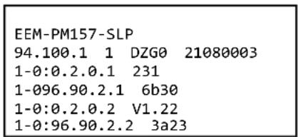
B 1 Metering firmware structure
The functionality of the DC energy meter is periodically processed in the main loop of the application layer. The interrupt service routines interrupt the main loop based on timer events and asynchronous events. Figure 7-5 shows the flow diagram for the metering firmware.
Main functionalities:
– Acquisition of relevant measurement values.
– Loss energy measurement and loss energy compensation.
- Redundant storage of energy registers.
- Continuous and non-reactive communication with the application part.
– Providing a strictly monotonic increasing second index.
- Controlling the metrological LED.
Figure 7-5 Firmware flow diagram of the metering part
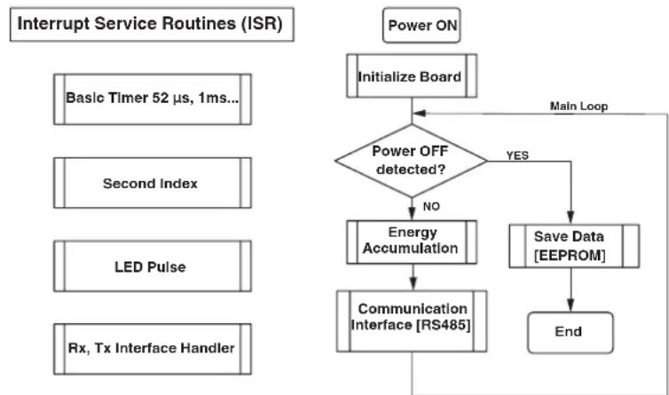
flowchart
graph TD
    A["Power ON"] --> B["Initialize Board"]
    B --> C{Power OFF detected?}
    C -->|NO| D["Energy Accumulation"]
    C -->|YES| E["Save Data [EEPROM"]]
    D --> F["Communication Interface [RS485"]]
    E --> G["End"]
    F --> H["Rx, Tx Interface Handler"]
    G --> H
    I["Basic Timer 52 µs, 1ms..."] --> B
    J["Second Index"] --> B
    K["LED Pulse"] --> B
    L["Rx"] --> F
    M["Main Loop"] --> C
B 2 Application firmware structure
To give an overview of the structure of the application firmware, it is illustrated as a block diagram in Figure 7-6. According to VDE-AR-E 2418-3-100, external components illustrate the part of the application controller within the system architecture.
Figure 7-6 EEM-PM157-SLP firmware block diagram of the application controller
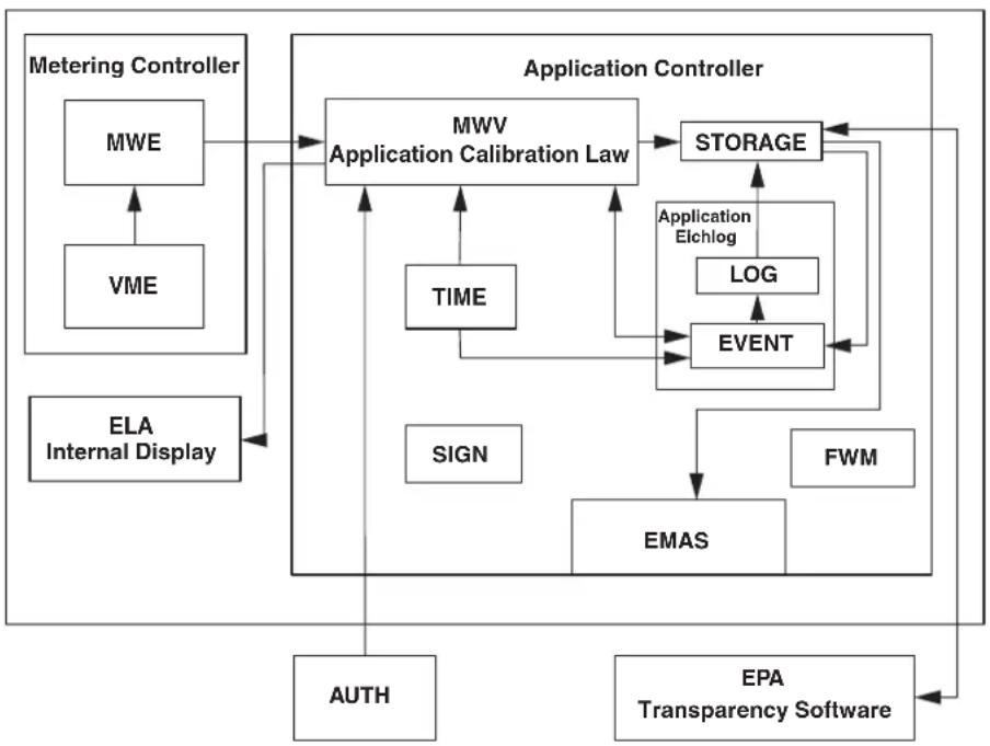
flowchart
graph TD
    A["Metering Controller"] --> B["MWE"]
    A --> C["VME"]
    A --> D["ELA"]
    A --> E["Internal Display"]
    F["Application Controller"] --> G["Application Calibration Law"]
    G --> H["STORAGE"]
    G --> I["TIME"]
    G --> J["LOG"]
    G --> K["EVENT"]
    G --> L["SIGN"]
    G --> M["EMAS"]
    G --> N["FWM"]
    G --> O["AUTH"]
    G --> P["EPA Transparency Software"]
    H --> Q["Application Elchlog"]
    I --> Q
    J --> Q
    K --> Q
    L --> Q
    M --> Q
    N --> Q
    O --> Q
    P --> Q
The functionality of the DC energy meter is periodically processed in the main loop of the application layer.
The application firmware is executed in the main loop. Internal interrupts provide timing functionalities. The usage of DMA and controlled memory access for all communication interfaces guarantees the absence of external feedback to the interfaces. Before processing input data, all data is verified. The listing below shows the main functionalities and their assignments to function blocks in the reference architecture of VDE-AR-E 2418-3-100.
Main functionalities
MWE, VME: Continuous communication and observation of the metering controller to retrieve DC energy meter readings. The communication is safeguarded by means of checksums and timeout monitoring.
ELA: Displaying metrological and informative DC energy meter readings on the display. This includes charging session and charging summary readings. Device status and operation mode are part of the display module. As an option, it is possible to connect an external display.
EPA: Providing signed DC energy meter readings for billing purposes. The format of the signed DC energy meter readings is OCMF 1.0. The hashing and signing as well as the canonical representation of the data are according to OCMF 1.0.
EMAS: OCMF data and the charging session storage are the base for the market surveillance interface.
FWM: A hash check continuously checks the integrity of the firmware. An invalid hash check of firmware or configuration storage will lead to a fatal error, further operation is prohibited.
STORAGE: The safe and secure storage of charging session readings and Eichlog is implemented in the storage module. All stored data is protected by a checksum and stored persistently. A failed check will cause the corresponding bit in the status word to be set. An Eichlog entry is generated.
LOG, EVENT: The application-part Eichlog handles all device events and stores the events chronologically and safely in the storage module.
SIGN: The service of generating signatures provided by the ECDSA-Module. The module hashes the data to be signed and generates a secp256k1 signature. The private key is generated during the production process inside the DC energy meter. The software architecture guarantees that the private key cannot be read out. The public key is available via the communication interface. The key pair signs the charging session data, and the Eichlog entries.
TIME: The firmware module time handles the RTC. It includes the monitoring and fault reaction of the RTC. It provides a local timestamp. The RTC is a so called "Info clock", its reading may not be used for billing purposes. The RTC may not be set during an active charging session. An Eichlog entry is generated, if the difference of the new set time and the current time is greater than 5 min.
MWV: The central part of the firmware is the calibration law application module. It is responsible for the proper conduct of a charging session. It is a data hub for all DC energy meter readings. Therefore, this module continuously retrieves and observes incoming data from the metering part and the external interfaces to handle charging sessions (start, stop), to trigger the storage of charging session data and Eichlog entries. It provides data and the system state for the display and links the DC energy meter readings to the info clock.
B 3 Security measures on the application controller
Measures against unintentional or intentional changes of the firmware
The application controller runs a system self-check to monitor the internal flash for firmware storage to avoid unintended changes of firmware. An SHA256 hash accomplishes this validation. The hash is calculated during the creation of the firmware image and patched into it. The application controller calculates the hash and compares the calculated to the patched one. This check is performed periodically every 10 s. A mismatch will cause a fatal error.
Measures against unintentional or intentional changes of the configuration
The configuration sets for the application firmware (operation, assembly, and production) are secured with a CRC16 and are stored separately in the storage. After loading a new configuration, the application controller calculates the CRC16 and compares it to the embedded CRC16 within the configuration itself. If both CRC16 match, the configuration is accepted.
Measures in case of a crash of the firmware (fault recovery, watchdog)
The system has internal watchdog. The application controller must toggle the input pin watchdog within 1.25 s. If the toggle window is missed, the watchdog resets the application controller.
B 4 Security measures on the metering controller
Measures against unintentional or intentional changes of the firmware
The MCU runs a system self-check to monitor the internal flash for firmware storage to avoid the changes for firmware by a CRC16. The application part checks this value periodically every 10 s. A mismatch will cause a fatal error.
Measures for secure memory of the energy registers (backup facilities)
The metering controller generates backup data for each energy register. The original data as well as the backup data are stored at different locations in the storage of the metering part. Each energy register data has a checksum. The metering controller will validate the main data according to its checksum. If there is any inconsistency, the backup data will be used.
Measures in case of a crash of the firmware (fault recovery, watchdog)
The system has an internal watchdog. The firmware will kick off the watchdog within 1.25 s. If it is not executed correctly, the whole system will be reset. A watchdog event is traced in the meter fatal error bit.
Measures against unintended or intended reset of the energy registers
Firmware does not provide the interface to reset the energy registers. If there was a situation that resulted in the current energy registers being reset, the firmware will recognize it by checksum validation. In this case, the backup data will be used.
Measures against malfunction caused of unintended load of the MCU (dynamic behavior)
The system has a timer monitor for each function block. The firmware will monitor each function block, with a timeout definition for each function block. If there is no normal operation for any part more than timeout duration, the system will reset this part.
C List of figures and list of tables
C 1 List of figures
Section 2
Figure 2-1: Schematic representation of the charging point structure ....7
Figure 2-2: Information on the device 8
Figure 2-3: Lateral printing on the DC energy meter 9
Figure 2-4: Operating and indication elements .....9
Figure 2-5: Schematic illustration of the dot-matrix display (unit: (mm)) ..... 10
Figure 2-7: Simplified block diagram of the DC energy meter 13
Section 4
Figure 4-1: Snap on DIN rail schematic 17
Figure 4-2: Connections of the DC energy meter 18
Figure 4-3: Wiring of the DC energy meter ....19
Figure 4-4: Cover of the DC energy meter 19
Figure 4-5: Security seal of the DC energy meter with safety punching ..... 19
Section 6
Figure 6-1: Schematic illustration of the internal display state machine .....27
Figure 6-2: Display — selftest state .....28
Figure 6-3: Display — info state ....28
Figure 6-4: Display — state operation ....29
Figure 6-5: Display — charging state ....31
Figure 6-6: Display — charging summary state ....32
Figure 6-7: Display — Eichlog state ....33
Figure 6-8: Display — Eichlog memory full ....34
Figure 6-9: Display — fatal error state ....34
Figure 6-10: Wiring of the DC energy meter ....36
Figure 6-11: DC energy meter energy flow import ....37
Figure 6-12: Example of a charging session initiated by a user presenting a smart card .... 38
Figure 6-13: Example of a charging session initiated by a user presenting a smart card .... 39
Section 7
Figure 7-1: Dimensioned front view of the housing (unit: (mm)) ....45
Figure 7-2: Dimensioned bottom view of the housing (unit: (mm)) ....45
Figure 7-3: Dimensioned side view of the housing (unit: (mm)) ....45
Appendix B
Figure 7-4: Firmware version verification within the display init state ....61
Figure 7-5: Firmware flow diagram of the metering part 61
Figure 7-6: EEM-PM157-SLP firmware block diagram of the application controller .... 62
C 2 List of tables
Section 2
Table 2-1: Abbreviations used in the product name....8
Table 2-2: Accuracy table....10
Table 2-3: Number of digits .... 10
Table 2-4: Display symbols....11
Section 6
Table 6-1: Display — selftest state transitions....28
Table 6-2: Display — info state transitions....28
Table 6-3: Display — public key state transitions....29
Table 6-4: Display information in states: operation, charging, and charging summary ...... 29
Table 6-5: OCMF display information in states: operation, charging, and charging summary .... 30
Table 6-6: Display — operation state transitions .... 30
Table 6-7: Display — charging state transitions....31
Table 6-8: Display — charging summary state transitions .....32
Table 6-9: Display information — Eichlog state ....33
Table 6-10: Display — Eichlog state transitions....33
Table 6-11: Display information — fatal error state....34
Table 6-12: Display — fatal error state transitions ..... 35
Table 6-13: Structure of an Eichlog entry....41
Appendix A
Table 7-1: Register of general device information ....47
Table 7-2: Register of general device information ....48
Table 7-3: Table of all status word meanings....49
Table 7-4: List of all device control registers....50
Table 7-5: List of all import-related energy registers....51
Table 7-6: Charging session register values....52
Table 7-7: Start charging session....52
Table 7-8: Stop charging session ....52
Table 7-9: OCMF charge point identification ....53
Table 7-10: Read public key OCMF....53
Table 7-11: Read public key as binary string ....53
Table 7-12: Transaction start, stop, and total values ....54
Table 7-13: Conversion from reading value to displayed value....54
Table 7-14: Charging history ....55
Table 7-15: Read charging history....55
Table 7-16: Read charging history — response payload ....55
Table 7-17: Delete charging history ....55
Table 7-18: Read signed OCMF entry 56
Table 7-19: Read last signed OCMF entry....56
Table 7-20: Content templates ....56
Table 7-21: RTC communication frame....56
Table 7-22: Eichlog register commands ....57
Table 7-23: Read Eichlog history (0x 1710)....57
Table 7-24: Read last Eichlog entry (0x1721)....57
Table 7-25: Eichlog types....58
Table 7-26: Commands in operation mode....59
D Glossary of terms
CI Charge-Point-Identification
CT Charge-Point-Identification-Type
Eichlog Calibration log
ECDSA Elliptic curve digital signature algorithm
Eichrecht Calibration law
EEM Electrical energy measurement
EV Electric vehicle
OBIS Object identification system
OBIS code A numerical code, which represents the physical quantity measured by the meter.
OCMF Open charge metering format
RC-network Electric circuit composed of resistors and capacitors.
RFID Radio-frequency identification
RTC Real-time clock
SMGW Smart meter gateway
SoC State of charge
TLS library Transport layer security library
Please observe the following notes
General Terms and Conditions of use for technical documentation
Phoenix Contact reserves the right to alter, correct, and/or improve the technical documentation and the products described in the technical documentation at its own discretion and without giving prior notice, insofar as this is reasonable for the user. The same applies to any technical changes that serve the purpose of technical progress.
The receipt of technical documentation (in particular user documentation) does not constitute any further duty on the part of Phoenix Contact to furnish information on modifications to products and/or technical documentation. You are responsible to verify the suitability and intended use of the products in your specific application, in particular with regard to observing the applicable standards and regulations. All information made available in the technical data is supplied without any accompanying guarantee, whether expressly mentioned, implied or tacitly assumed.
In general, the provisions of the current general Terms and Conditions of Phoenix Contact apply exclusively, in particular as concerns any warranty liability.
This manual, including all illustrations contained herein, is copyright protected. Any changes to the contents or the publication of extracts of this document are prohibited.
Phoenix Contact reserves the right to register its own intellectual property rights for the product identifications of Phoenix Contact products that are used here. Registration of such intellectual property rights by third parties is prohibited.
Other product identifications may be afforded legal protection, even where they may not be indicated as such.
How to contact us
Internet
Up-to-date information on Phoenix Contact products and our Terms and Conditions can be found on the Internet at: phoenixcontact.com
Make sure you always use the latest documentation. It can be downloaded at: phoenixcontact.net/products
Subsidiaries
If there are any problems that cannot be solved using the documentation, please contact your Phoenix Contact subsidiary. Subsidiary contact information is available at phoenixcontact.com.
Published by PHOENIX CONTACT GmbH & Co. KG
PHOENIX CONTACT Development and Manufacturing, Inc. 586 Fulling Mill Road Middletown, PA 17057 USA
Should you have any suggestions or recommendations for improvement of the contents and layout of our manuals, please send your comments to: tecdoc@phoenixcontact.com
PHOENIX CONTACT GmbH & Co. KG
Flachsmarktstraße 8
32825 Blomberg, Germany
Phone: +49 5235 3-00
Fax: +49 5235 3-41200
E-mail: info@phoenixcontact.com
phoenixcontact.com
- kW DC energy meter
- User manual
- Table of contents
- For your safety....5
- Device description....7
- Quick-start guide 15
- Mounting and installation....17
- Configuration....21
- Operation....25
- For your safety
- Identification of warning notes
- DANGER
- WARNING
- CAUTION
- Qualification of users
- Field of application of the product
- Intended use
- Foreseeable misuse
- Product changes
- Safety notes
- CAUTION:
- Device description
- Abbreviations
- Information on the device
- Operating and indication elements
- LED
- Accuracy test
- LCD
- Display symbols
- Communication interface
- System architecture
- Quick-start guide
- First steps: configuration of a single DC energy meter
- Normal Mode
- Assembly Mode
- Configuration of multiple DC energy meter
- Mounting and installation
- DANGER: High voltage and/or current
- Overvoltage protection
- Requirements for charging station and controller
- Requirements for transparency software
- Snapping the device onto the DIN rail
- Installation
- DANGER: Unforeseen consequences of poor installation
- Wiring procedure:
- Cover and seal
- Configuration
- Application configuration
- Serial interfaces
- Application configuration — display
- Operation
- Charging
- Upper line Registers
- Lower line Registers
- Charging summary
- Display properties
- Backlight configuration 0: backlight permanently off
- Backlight button press 5000 (5 s) (default) timeout:
- Show public key True
- Application configuration — charging and feature
- Charging configuration
- Assembly configuration
- Metrology
- Operation
- Device statuses
- Alterable DC energy meter settings within the production mode
- Transition conditions
- Assembly mode
- Alterable DC energy meter settings within assembly mode
- Operation mode
- Alterable DC energy meter settings within operation mode
- Internal display state machine
- Selftest state
- Info state
- Public key state
- Operation state
- OCMF display
- Charging state
- Charging summary state
- Eichlog state
- Eichlog memory full
- Fatal error state
- Line loss energy calculation
- Energy flow
- Charging session
- Start
- Stop after power failure
- Charging session storage
- Clock
- The following rules apply:
- Eichlog
- External display
- Technical data
- Product specification
- Dimensions
- Applicable technical standards
- A Registers
- Legend of access rights:
- A 1 Device information
- A 2 Status word
- A 3 Device control
- A 4 Energy and instantaneous registers
- A 5 Charging session
- Transaction start values
- Import
- A 6 Charging history
- Content templates (available from firmware version v232+)
- A 7 Eichlog (calibration law)
- Eichlog types
- A 8 Commands in operation mode
- B Firmware
- B 1 Metering firmware structure
- Main functionalities:
- B 2 Application firmware structure
- Main functionalities
- B 3 Security measures on the application controller
- Measures against unintentional or intentional changes of the firmware
- Measures against unintentional or intentional changes of the configuration
- Measures in case of a crash of the firmware (fault recovery, watchdog)
- B 4 Security measures on the metering controller
- Measures for secure memory of the energy registers (backup facilities)
- Measures against unintended or intended reset of the energy registers
- Measures against malfunction caused of unintended load of the MCU (dynamic behavior)
- C List of figures and list of tables
- C 1 List of figures
- Section 2
- Section 4
- Section 6
- Section 7
- Appendix B
- C 2 List of tables
- Appendix A
- D Glossary of terms
- Please observe the following notes
- General Terms and Conditions of use for technical documentation
- How to contact us
- Internet
- Subsidiaries
- Published by PHOENIX CONTACT GmbH & Co. KG
Brand : Phoenix Contact
Model : EEM-PM157-SLP
Category : Measurement