
PMP 450b - Network Equipment Cambium Networks - Free user manual and instructions
Find the device manual for free PMP 450b Cambium Networks in PDF.


| Product Type | Point-to-Multipoint Subscriber Module (SM) |
| Model | PMP 450b (Mid-Gain and High Gain variants) |
| Frequency Band | 4.9 – 5.925 GHz (5 GHz band) |
| Channel Bandwidth | 5, 7, 10, 15, 20, 30, 40 MHz |
| Max Data Rate | Up to 310 Mbps (40 MHz channel, 5 ms frame) |
| Modulation | MIMO-B, up to 256 QAM |
| Max Conducted Tx Power | 27 dBm (varies by band and country) |
| Antenna Type (Mid-Gain) | Integrated, 16 dBi gain |
| Antenna Type (High Gain) | Integrated dish, 23 dBi gain |
| Dimensions (Mid-Gain) | 12.5 x 12.5 x 3.0 in (318 x 318 x 76 mm) |
| Dimensions (High Gain) | 24 in diameter dish, depth ~12 in |
| Weight (Mid-Gain) | ~7.5 lb (3.4 kg) |
| Weight (High Gain) | ~12 lb (5.4 kg) |
| Ethernet Interface | 1x 1000Base-T with PoE input (Main port) |
| Power Supply | PoE (IEEE 802.3at or passive, 56V DC from injector) |
| Power Consumption | ~20 W typical |
| Environmental Rating | IP66 (outdoor, weatherproof) |
| Management | Web GUI, SNMP v1/v2c/v3, cnMaestro, RADIUS |
| Security | AES-128/256 encryption, SM authentication, RADIUS |
| Duplexing | TDD (symmetric/asymmetric), GPS synchronized |
| Compliance | FCC, ISED, CE, RoHS, WEEE |
Frequently Asked Questions - PMP 450b Cambium Networks
User questions about PMP 450b Cambium Networks
0 question about this device. Answer the ones you know or ask your own.
Ask a new question about this device
Download the instructions for your Network Equipment in PDF format for free! Find your manual PMP 450b - Cambium Networks and take your electronic device back in hand. On this page are published all the documents necessary for the use of your device. PMP 450b by Cambium Networks.
USER MANUAL PMP 450b Cambium Networks
natural_image
Street view with surveillance camera mounted on elevated bridge, vehicles in background (no visible text or symbols)
Cambium Networks™

natural_image
Aerial view of a town nestled in a rocky valley at dusk, with a river and hills in the background (no visible text or symbols)
natural_image
Young girl in blue shirt using tablet at a classroom (no visible text or symbols)
natural_image
Top-down view of people at a table with drinks and drinks, bottom-down view of an oil rig on a desert road under cloudy sky (no text or symbols)USER GUIDE
PMP/PTP 450 Series
Covers
PMP 450 AP / PMP 450 SM / PTP 450 BH / PMP 450d
PMP 450i / PTP 450i
PMP/PTP 450b Mid-Gain / 450b High-Gain
PMP 450m
PMP 430

natural_image
Two-panel image: top shows a coastal town with ships and greenery, bottom shows a man working at a desk with a laptop (no visible text or symbols)Accuracy
While reasonable efforts have been made to assure the accuracy of this document, Cambium Networks assumes no liability resulting from any inaccuracies or omissions in this document, or from use of the information obtained herein. Cambium reserves the right to make changes to any products described herein to improve reliability, function, or design, and reserves the right to revise this document and to make changes from time to time in content hereof with no obligation to notify any person of revisions or changes. Cambium does not assume any liability arising out of the application or use of any product, software, or circuit described herein; neither does it convey license under its patent rights or the rights of others. It is possible that this publication may contain references to, or information about Cambium products (machines and programs), programming, or services that are not announced in your country. Such references or information must not be construed to mean that Cambium intends to announce such Cambium products, programming, or services in your country.
Copyrights
This document, Cambium products, and 3 ^rd Party software products described in this document may include or describe copyrighted Cambium and other 3 ^rd Party supplied computer programs stored in semiconductor memories or other media. Laws in the United States and other countries preserve for Cambium, its licensors, and other 3 ^rd Party supplied software certain exclusive rights for copyrighted material, including the exclusive right to copy, reproduce in any form, distribute and make derivative works of the copyrighted material. Accordingly, any copyrighted material of Cambium, its licensors, or the 3 ^rd Party software supplied material contained in the Cambium products described in this document may not be copied, reproduced, reverse engineered, distributed, merged or modified in any manner without the express written permission of Cambium. Furthermore, the purchase of Cambium products shall not be deemed to grant either directly or by implication, estoppel, or otherwise, any license under the copyrights, patents or patent applications of Cambium or other 3rd Party supplied software, except for the normal non-exclusive, royalty free license to use that arises by operation of law in the sale of a product.
Restrictions
Software and documentation are copyrighted materials. Making unauthorized copies is prohibited by law. No part of the software or documentation may be reproduced, transmitted, transcribed, stored in a retrieval system, or translated into any language or computer language, in any form or by any means, without prior written permission of Cambium.
License Agreements
The software described in this document is the property of Cambium and its licensors. It is furnished by express license agreement only and may be used only in accordance with the terms of such an agreement.
High Risk Materials
Cambium and its supplier(s) specifically disclaim any express or implied warranty of fitness for any high risk activities or uses of its products including, but not limited to, the operation of nuclear facilities, aircraft navigation or aircraft communication systems, air traffic control, life support, or weapons systems (“High Risk Use”). Any “High Risk Use” is unauthorized, is made at your own risk and you shall be responsible for any and all losses, damage or claims arising out of any High Risk Use.
© 2018 Cambium Networks Limited. All Rights Reserved.
Contents
Contents ...... i
List of Figures ......xiv
List of Tables ....xx
About This User Guide....1
Contacting Cambium Networks....1
Purpose....2
Product notation conventions in document 2
Cross references 3
Feedback....3
Important regulatory information....4
Application software....4
USA specific information....4
Canada specific information....5
EU Declaration of Conformity 7
Specific expertise and training for professional installers....7
Ethernet networking skills....8
Lightning protection 8
Training....8
Problems and warranty 9
Reporting problems 9
Repair and service 9
Hardware warranty....9
Security advice....10
Warnings, cautions, and notes 11
Warnings 11
Cautions....11
Notes....11
Caring for the environment 12
In EU countries....12
In non-EU countries....12
Chapter 1: Product description....1-1
Overview of the 450 Platform Family 1-2
Purpose....1-2
PMP 450m Series....1-2
PMP/PTP 450i Series 1-4
PMP/PTP 450b Series....1-8
PMP/PTP 450 Series 1-9
Supported interoperability for 450m/450i/450b/450 Series 1-12
Typical deployment....1-13
Product variants....1-15
Wireless operation 1-16
Time division duplexing....1-16
Encryption....1-19
MIMO 1-19
MU-MIMO 1-19
System management 1-21
Management agent....1-21
Web server....1-21
Remote Authentication Dial-in User Service (RADIUS)....1-23
Network Time Protocol (NTP)....1-23
cnMaestro™ 1-24
Wireless Manager (WM) 1-24
Radio recovery mode....1-26
Chapter 2: System hardware....2-1
System Components....2-2
Point-to-Multipoint (PMP) 2-2
Backhaul (PTP)....2-6
450 Platform Family interfaces....2-8
ATEX/HAZLOC variants....2-18
Diagnostic LEDs....2-19
Power supply options 2-23
ODU mounting brackets & accessories 2-32
Lightning protection 2-32
ODU interfaces....2-34
PMP 450m Series 5 GHz AP 2-34
PMP 450m Series 3GHz AP 2-35
PMP/PTP 450i 2-36
PMP/PTP 450b Mid-Gain SM....2-38
PMP/PTP 450b High Gain SM 2-39
Cabling....2-40
Ethernet standards and cable lengths....2-40
Outdoor copper Cat5e Ethernet cable 2-41
SFP module kits 2-42
Main Ethernet port....2-44
Aux port 2-44
Ethernet cable testing....2-48
Lightning protection unit (LPU) and grounding kit 2-50
DC LPU and Grounding Kit 2-51
Cable grounding kit....2-53
Antennas and antenna cabling....2-54
Antenna requirements 2-54
Supported external AP antennas....2-54
Supported external BH/SM antenna 2-54
RF cable and connectors....2-55
Antenna accessories 2-55
GPS synchronization....2-56
GPS synchronization description....2-56
Universal GPS (UGPS) 2-56
CMM5 2-58
CMM5 Controller Module....2-61
CMM5 Injector Module 2-62
CMM5 Injector Compatibility Matrix....2-62
CMM5 Specifications....2-63
CMM4 (Rack Mount) 2-65
CMM4 (Cabinet with switch)....2-68
CMM4 (Cabinet without switch) 2-68
CMM3/CMMmicro 2-69
Installing a GPS receiver....2-71
GPS receiver location....2-71
Mounting the GPS receiver 2-72
Cabling the GPS Antenna....2-73
Installing and connecting the GPS LPU 2-73
Ordering the components....2-74
Chapter 3: System planning....3-1
Typical deployment....3-2
ODU with PoE interface to PSU 3-2
Site planning....3-7
Site selection for PMP/PTP radios....3-7
Power supply site selection 3-8
Maximum cable lengths....3-8
Grounding and lightning protection....3-8
ODU and external antenna location 3-10
ODU ambient temperature limits....3-10
ODU wind loading 3-11
Hazardous locations....3-16
Drop cable grounding points....3-16
Lightning Protection Unit (LPU) location....3-17
Radio Frequency planning....3-18
Regulatory limits....3-18
Conforming to the limits 3-18
Available spectrum....3-18
Analyzing the RF Environment 3-19
Channel bandwidth 3-19
Anticipating Reflection of Radio Waves 3-19
Obstructions in the Fresnel Zone 3-20
Planning for co-location 3-20
Multiple OFDM Access Point Clusters....3-21
Considerations on back-to-back frequency reuse....3-23
Link planning 3-28
Range and obstacles....3-28
Path loss 3-28
Calculating Link Loss 3-29
Calculating Rx Signal Level....3-29
Calculating Fade Margin....3-30
Adaptive modulation 3-30
Planning for connectorized units....3-31
When to install connectorized units....3-31
Choosing external antennas ....3-31
Calculating RF cable length (5.8 GHz FCC only) 3-31
Data network planning 3-33
Understanding addresses....3-33
Dynamic or static addressing....3-33
DNS Client 3-34
Network Address Translation (NAT)....3-34
Developing an IP addressing scheme 3-35
Address Resolution Protocol....3-36
Allocating subnets....3-36
Selecting non-routable IP addresses 3-36
Translation bridging 3-37
Engineering VLANs 3-37
Network management planning 3-41
Planning for SNMP operation 3-41
Enabling SNMP 3-41
Security planning....3-42
Isolating AP/BHM from the Internet 3-42
Encrypting radio transmissions....3-42
Planning for HTTPS operation....3-43
Planning for SNMPv3 operation....3-43
Managing module access by passwords 3-44
Planning for RADIUS operation....3-45
Filtering protocols and ports....3-45
Encrypting downlink broadcasts 3-49
Isolating SMs in PMP 3-49
Filtering management through Ethernet....3-49
Allowing management from only specified IP addresses 3-50
Configuring management IP by DHCP 3-50
Controlling PPPoE PADI Downlink Forwarding 3-51
Remote AP Deployment....3-52
Remote AP (RAP) Performance 3-53
Example Use Case for RF Obstructions....3-53
Example Use Case for Passing Sync 3-54
Physical Connections Involving the Remote AP 3-55
Passing Sync signal 3-57
Wiring to Extend Network Sync 3-60
Chapter 4: Legal and regulatory information....4-1
Cambium Networks end user license agreement....4-2
Definitions 4-2
Acceptance of this agreement....4-2
Grant of license 4-2
Conditions of use 4-3
Title and restrictions 4-4
Confidentiality 4-4
Right to use Cambium's name....4-5
Transfer 4-5
Updates 4-5
Maintenance....4-5
Disclaimer....4-6
Limitation of liability....4-6
U.S. government 4-6
Term of license 4-7
Governing law 4-7
Assignment 4-7
Survival of provisions....4-7
Entire agreement....4-7
Third party software 4-7
Compliance with safety standards 4-22
Electrical safety compliance 4-22
Electromagnetic compatibility (EMC) compliance....4-22
Human exposure to radio frequency energy....4-23
Hazardous location compliance....4-37
Compliance with radio regulations....4-39
Type approvals....4-40
Brazil specific information....4-41
Australia Notification 4-41
Regulatory Requirements for CEPT Member States (www.cept.org) 4-41
Chapter 5: Preparing for installation....5-1
Safety 5-2
Hazardous locations....5-2
Power lines....5-2
Working at heights 5-2
Power supply 5-2
Grounding and protective earth 5-3
Powering down before servicing....5-3
Primary disconnect device....5-3
External cables 5-3
RF exposure near the antenna 5-3
Minimum separation distances....5-3
Grounding and lightning protection requirements....5-4
Grounding cable installation methods....5-4
Siting ODUs and antennas 5-4
Thermal Safety 5-4
Preparing for installation....5-6
ODU pre-configuration....5-6
Preparing personnel 5-6
Preparing inventory....5-6
Preparing tools....5-7
Testing system components 5-8
Unpacking Components 5-8
Preparing the ODU 5-8
Configuring Link for Test 5-17
Configuring the management PC 5-17
Logging into the web interface - AP/SM/BH....5-18
Using the Quick Start Configuration Wizard of the AP/BHM....5-18
Chapter 6: Installation....6-1
ODU variants and mounting bracket options....6-2
Mount the ODU, LPU and surge suppressor....6-3
Attach ground cables to the ODU....6-3
Mount the ODU on the mast....6-6
Mount the top LPU 6-13
Mount the Surge Suppressor....6-13
General protection installation....6-16
Installing the copper Cat5e Ethernet interface....6-22
Install the main drop cable....6-22
Install the bottom LPU to PSU drop cable....6-25
Installing external antennas to a connectorized ODU 6-27
PMP 450i Series 6-27
PMP 450 Series 6-36
PMP 450i Series AP 900 MHz 6-45
PMP 450 Series SM 900 MHz 6-53
Installing an integrated ODU 6-57
PMP 450m Series - 5 GHz AP 6-57
PMP 450m Series - 3 GHz AP 6-60
PMP/PTP 450i Series - AP/SM/BH 6-64
Connecting Cat5e Ethernet cable 6-65
Connecting an RJ45 and gland to a unit....6-65
Disconnecting an RJ45 and gland from a unit 6-67
Installing ODU 6-68
Installing a 450 Platform Family AP....6-68
Installing a 450 Platform Family SM....6-69
Installing a 450 Platform Family BHM 6-70
Installing a 450 Platform Family BHS 6-71
Configuring the Link....6-72
Monitoring the Link 6-72
Installing the AC Power Injector 6-73
Installing CMM4....6-74
Supplemental installation information....6-75
Stripping drop cable 6-75
Creating a drop cable grounding point 6-76
Attaching and weatherproofing an N type connector 6-79
Chapter 7: Configuration....7-1
Preparing for configuration 7-2
Safety precautions....7-2
Regulatory compliance....7-2
Connecting to the unit....7-3
Configuring the management PC 7-3
Connecting to the PC and powering up....7-4
Using the web interface 7-5
Logging into the web interface....7-5
Web GUI....7-7
Using the menu options....7-7
Quick link setup 7-13
Initiating Quick Start Wizard 7-13
Configuring time settings....7-19
Powering the SM/BHS for test....7-20
Viewing the Session Status of the AP/BHM to determine test registration 7-21
Configuring IP and Ethernet interfaces 7-24
Configuring the IP interface....7-25
Auxiliary port....7-28
NAT, DHCP Server, DHCP Client and DMZ 7-29
DHCP - BHS....7-46
Reconnecting to the management PC....7-46
VLAN configuration for PMP....7-46
VLAN configuration for PTP 7-57
PPPoE page of SM....7-61
IP4 and IPv6....7-64
Upgrading the software version and using CNUT 7-69
Checking the installed software version....7-69
Upgrading to a new software version....7-69
General configuration 7-73
PMP 450m and PMP/PTP 450i Series....7-73
PMP/PTP 450 Series 7-91
Configuring Unit Settings page....7-96
Setting up time and date 7-100
Time page of 450 Platform Family - AP/BHM 7-100
Configuring synchronization 7-102
Configuring security....7-104
Managing module access by password....7-105
Isolating from the internet - APs/BHMs....7-108
Encrypting radio transmissions....7-108
Requiring SM Authentication....7-109
Filtering protocols and ports....7-110
Encrypting downlink broadcasts....7-113
Isolating SMs....7-113
Filtering management through Ethernet....7-114
Allowing management only from specified IP addresses 7-114
Restricting radio Telnet access over the RF interface....7-114
Configuring SNMP Access 7-117
Configuring Security 7-119
Configuring radio parameters....7-137
PMP 450m Series - configuring radio....7-138
PMP/PTP 450i Series - configuring radio....7-147
PMP/PTP 450b Series - configuring radio 7-174
PMP/PTP 450 Series - configuring radio 7-179
Custom Frequencies page 7-196
DFS for 5 GHz Radios 7-199
MIMO-A mode of operation....7-209
Improved PPS performance of 450 Platform Family....7-211
Setting up SNMP agent 7-213
Configuring SM/BHS's IP over-the-air access 7-214
Configuring SNMP 7-216
Configuring syslog 7-222
Syslog event logging 7-222
Configuring system logging 7-223
Configuring remote access....7-227
Accessing SM/BHS over-the-air by Web Proxy....7-227
Monitoring the Link 7-229
Link monitoring procedure 7-229
Exporting Session Status page of AP/BHM 7-231
Configuring quality of service 7-232
Maximum Information Rate (MIR) Parameters....7-232
Token Bucket Algorithm 7-232
MIR Data Entry Checking 7-233
Committed Information Rate (CIR) 7-233
Bandwidth from the SM Perspective 7-234
Interaction of Burst Allocation and Sustained Data Rate Settings....7-234
SM Prioritization....7-234
Weighted Fair Queuing (WFQ)....7-237
High-priority Bandwidth Traffic 7-240
Traffic Scheduling....7-242
Setting the Configuration Source 7-243
Configuring Quality of Service (QoS) 7-246
Installation Color Code 7-258
Zero Touch Configuration Using DHCP Option 66 7-259
Configuration Steps 7-259
Troubleshooting....7-264
Configuring Radio via config file 7-265
Import and Export of config file 7-265
Configuring cnMaestro™ Connectivity....7-267
Configuring a RADIUS server 7-273
Understanding RADIUS for PMP 450 Platform Family....7-273
Choosing Authentication Mode and Configuring for Authentication Servers - AP .... 7-274
SM Authentication Mode - Require RADIUS or Follow AP 7-279
Handling Certificates....7-285
Configuring RADIUS servers for SM authentication....7-286
Assigning SM management IP addressing via RADIUS....7-288
Configuring RADIUS server for SM configuration 7-288
Configuring RADIUS server for SM configuration using Zero Touch feature......7-292
Using RADIUS for centralized AP and SM user name and password management..7-293
RADIUS Device Data Accounting 7-299
RADIUS Device Re-authentication 7-302
RADIUS Change of Authorization and Disconnect Message....7-304
Microsoft RADIUS support....7-306
Cisco ACS RADIUS Server Support....7-310
Configuring VSA 7-313
Configuring Ping Watchdog....7-317
Chapter 8: Tools....8-1
Using Spectrum Analyzer tool 8-2
Mapping RF Neighbor Frequencies....8-2
Spectrum Analyzer tool....8-3
Remote Spectrum Analyzer tool 8-13
Using the Alignment Tool 8-16
Aiming page and Diagnostic LED - SM/BHS....8-17
Alignment Tone....8-21
Using the Link Capacity Test tool....8-23
Performing Link Test....8-23
Performing Extrapolated Link Test 8-28
Link Capacity Test page of AP....8-29
Link Capacity Test page of BHM/BHS/SM....8-31
Using AP Evaluation tool....8-32
AP Evaluation page....8-32
Using BHM Evaluation tool 8-36
BHM Evaluation page of BHS 8-36
Using the OFDM Frame Calculator tool 8-40
Using the Subscriber Configuration tool....8-45
Using the Link Status tool....8-46
Link Status - AP/BHM 8-47
Link Status - SM/BHS 8-50
Using BER Results tool 8-53
Using the Sessions tool....8-54
Using the Ping Test tool....8-55
Chapter 9: Operation 9-1
System information....9-2
Viewing General Status 9-2
Viewing Session Status....9-24
Viewing Remote Subscribers 9-34
Interpreting messages in the Event Log 9-34
Viewing the Network Interface 9-37
Viewing the Layer 2 Neighbors....9-38
System statistics....9-39
Viewing the Scheduler statistics....9-39
Viewing list of Registration Failures statistics....9-41
Interpreting Bridging Table statistics 9-43
Interpreting Translation Table statistics....9-43
Interpreting Ethernet statistics 9-44
Interpreting RF Control Block statistics 9-47
Interpreting Sounding statistics for AP 9-1
Interpreting VLAN statistics....9-3
Interpreting Data Channels statistics....9-4
Interpreting MIR/Burst statistics....9-6
Interpreting Throughput statistics....9-9
Interpreting Overload statistics 9-12
Interpreting DHCP Relay statistics 9-14
Interpreting Filter statistics....9-16
Viewing ARP statistics....9-17
Viewing NAT statistics....9-17
Viewing NAT DHCP Statistics 9-19
Interpreting Sync Status statistics....9-20
Interpreting PPPoE Statistics for Customer Activities....9-21
Interpreting Bridge Control Block statistics 9-23
Interpreting Pass Through Statistics....9-26
Interpreting SNMPv3 Statistics 9-27
Interpreting syslog statistics 9-29
Interpreting Frame Utilization statistics 9-30
Radio Recovery....9-35
Radio Recovery Console- PMP/PTP 450i/450b and PMP 450m....9-35
Default Mode (or Default/Override Plug) - PMP/PTP 450 Series ......9-38
Chapter 10: Reference information....10-1
Equipment specifications....10-2
Specifications for 5 GHz PMP 450m Series - AP 10-2
Specifications for 3 GHz PMP 450m Series - AP 10-6
Specifications for PMP 450i Series - AP....10-10
Specifications for PMP 450i Series - SM....10-16
Specifications for PTP 450i Series - BH....10-22
Specifications for PMP/PTP 450b Mid-Gain Series - SM....10-27
Specifications for PMP/PTP 450b High Gain Series - SM....10-32
Specifications for PMP 450 Series - AP....10-36
Specifications for PMP 450 Series - SM....10-41
Specifications for PTP 450 Series - BH 10-46
PSU specifications....10-51
Data network specifications....10-53
Ethernet interface....10-53
Wireless specifications 10-55
General wireless specifications 10-55
Link Range and Throughput 10-56
Country specific radio regulations 10-57
Type approvals....10-57
DFS for 2.4 and 5 GHz Radios....10-59
Equipment Disposal 10-61
Waste (Disposal) of Electronic and Electric Equipment 10-61
Country specific maximum transmit power....10-62
Maximum transmit power 900 MHz band....10-62
Maximum transmit power 2.4 GHz band....10-63
Maximum transmit power 3.5 GHz band 10-64
Maximum transmit power 3.65 GHz band....10-65
Maximum transmit power 4.9 GHz band....10-65
Maximum transmit power 5.1 GHz band....10-67
Maximum transmit power 5.2 GHz band 10-70
Maximum transmit power 5.4 GHz band....10-74
Maximum transmit power 5.8 GHz band....10-82
Country specific frequency range 10-87
Frequency range 900 MHz band....10-87
Frequency range 2.4 GHz band 10-88
Frequency range 3.5 GHz band 10-88
Frequency range 3.65 GHz band 10-89
Frequency range 4.9 GHz band....10-90
Frequency range 5.1 GHz band 10-91
Frequency range 5.2 GHz band 10-94
Frequency range 5.4 GHz band 10-97
Frequency range 5.8 GHz band 10-103
FCC specific information....10-109
FCC compliance testing 10-109
FCC IDs....10-109
FCC approved antenna list 10-119
Innovation Science and Economic Development Canada (ISEDC) specific information ....10-123
900 MHz ISEDC notification....10-123
4.9 GHz ISEDC notification....10-123
5.2 GHz and 5.4 GHz ISEDC notification ....10-123
Utilisation de la bande 5.2 and 5.4 GHz ISEDC 10-124
ISEDC notification 5.8 GHz 10-124
ISEDC certification numbers....10-125
Canada approved antenna list 10-126
Chapter 11: Troubleshooting....11-1
General troubleshooting procedure....11-2
General planning for troubleshooting....11-2
General fault isolation process....11-3
Secondary Steps....11-4
Troubleshooting procedures....11-5
Module has lost or does not establish connectivity 11-5
NAT/DHCP-configured SM has lost or does not establish connectivity ....11-7
SM Does Not Register to an AP 11-9
Module has lost or does not gain sync 11-10
Module does not establish Ethernet connectivity 11-11
CMM4 does not pass proper GPS sync to connected modules....11-12
Module Software Cannot be Upgraded....11-13
Module Functions Properly, Except Web Interface Became Inaccessible .....11-13
Contents
Power-up troubleshooting....11-15
Registration and connectivity troubleshooting 11-16
SM/BMS Registration....11-16
Logs 11-17
Persistent Logging 11-17
Appendix A - 450m Reference information....I
A.1 Specifications.... I
A.2 450m overload....I
Glossary .... III
List of Figures
Figure 1 PMP/PTP 450 Platform Family typical bridge deployment....1-13
Figure 2 TDD frame division....1-16
Figure 3 3GHz PMP 450m Series interfaces....2-8
Figure 4 5GHz PMP 450m Series interfaces....2-9
Figure 5 PMP/PTP 450i interfaces....2-10
Figure 6 PMP 450b Mid-Gain Series - SM interfaces....2-12
Figure 7 PMP 450b Series - SM interfaces (High Gain)....2-13
Figure 8 PMP/PTP 450 Series - AP interfaces ......2-14
Figure 9 PMP/PTP 450 Series - SM/BH interfaces....2-15
Figure 10 PMP/PTP 450 Series - SM/BH Connectorized interfaces ......2-16
Figure 11 PMP 450d Series - SM Integrated Dish ....2-17
Figure 12 PMP 450 Series - SM 3 GHz Integrated 2-17
Figure 13 PTP 450 Series - BHM/BHS....2-17
Figure 14 AP/BHM diagnostic LEDs, viewed from unit front....2-19
Figure 15 AP/BH diagnostic LEDs, viewed from unit front....2-21
Figure 16 AC Power Injector interfaces 2-25
Figure 17 AC+DC Enhanced Power Injector interfaces....2-26
Figure 18 -48 V DC Power Injector interfaces....2-28
Figure 19 -20 to 32 VDC Power Injector interfaces....2-29
Figure 20 Gigabit Enet Capable power supply....2-31
Figure 21 PMP 450m Series - AP rear interfaces....2-34
Figure 22 PMP 450m 3GHz - AP rear interfaces....2-35
Figure 23 PMP/PTP 450i Series - ODU rear interfaces....2-36
Figure 24 PMP/PTP 450i Series - Connectorized ODU antenna interfaces .....2-37
Figure 25 PMP/PTP 450b Mid-Gain SM - ODU rear interfaces ......2-38
Figure 26 PMP/PTP 450b High Gain SM - ODU rear interfaces....2-39
Figure 27 Outdoor drop cable....2-41
Figure 28 Optical SFP transceiver module....2-43
Figure 29 Long cable gland....2-43
Figure 30 Alignment Tone Cable....2-45
Figure 31 RJ12 Alignment Tone Cable....2-45
Figure 32 Cable gland (part number #N000065L033) ......2-47
Figure 33 Cable grounding kit....2-53
Figure 34 UGPS....2-56
Figure 35 Cluster Management: Scenario 1....2-59
Figure 36 Cluster Management: Scenario 2....2-61
Figure 37 Controller Module....2-61
Figure 38 Injector Module 2-62
Figure 39 CMM4 (Rack Mount)....2-65
Figure 40 CMM4 56 V power adapter (dongle)....2-66
Figure 41 CMM4 power adapter cabling diagram....2-66
Figure 42 CMM4 (Cabinet with switch)....2-68
Figure 43 CMM3....2-70
Figure 44 Pole mounted CMM3 2-70
Figure 45 GPS antenna mounting 2-72
Figure 46 Mast or tower installation....3-2
Figure 47 Wall installation ....3-3
Figure 48 Roof installation....3-4
Figure 49 GPS receiver wall installation....3-5
Figure 50 GPS receiver tower or mast installation....3-6
Figure 51 Rolling sphere method to determine the lightning protection zones ....3-9
Figure 52 Example layout of 16 Access Point sectors (ABCD), 90-degree sectors....3-21
Figure 53 Example layout of 6 Access Point sectors (ABC), 60-degree sectors....3-22
Figure 54 Reflection....3-24
Figure 55 Sector Antenna....3-25
Figure 56 cnMedusa Antenna....3-26
Figure 57 PMP 450m Series AP antenna beam 3-27
Figure 58 Determinants in Rx signal level....3-29
Figure 59 Cambium networks management domain....3-34
Figure 60 Example of IP address in Class B subnet....3-36
Figure 61 Categorical protocol filtering....3-47
Figure 62 Remote AP deployment....3-52
Figure 63 Example for 900-MHz remote AP behind 5 GHz SM....3-54
Figure 64 Remote AP wired to SM that also serves a customer ....3-55
Figure 65 Remote AP wired to SM that serves as a relay....3-56
Figure 66 Additional link to extend network sync, Design 3....3-57
Figure 67 Additional link to extend network sync, Design 4....3-58
Figure 68 Additional link to extend network sync, Design 5....3-59
Figure 69 Co-located AP or BH timing master Sync Setting configuration ....3-60
Figure 70 Pin 1 location ....5-11
Figure 71 Straight-through Ethernet Cable....5-13
Figure 72 Crossover Ethernet Cable 5-13
Figure 73 AP/BHM to UGPS cable....5-15
Figure 74 Alignment tone cable pin configuration ....5-16
Figure 75 RJ-12 pinout for the default plug....5-16
Figure 76 PMP 450 900 MHz SM grounding....6-6
Figure 77 Gigabit Ethernet Surge Suppressor 6-14
Figure 78 600SSH Surge Suppressor - inside....6-15
Figure 79 Grounding cable minimum bend radius and angle ....6-17
Figure 80 Grounding and lightning protection on wall....6-19
Figure 81 Grounding and lightning protection on mast or tower 6-20
Figure 82 Grounding and lightning protection on building 6-21
Figure 83 RJ45 cable 6-23
Figure 84 AP antenna parts....6-30
Figure 85 Antenna top plate ....6-31
Figure 86 Attaching antenna plate to the AP 6-31
Figure 87 Attaching the plate....6-32
Figure 88 Connect the port A and B to the PMP 450i AP....6-32
Figure 89 AP antenna upper bracket assembly....6-33
Figure 90 AP antenna upper bracket attached to upper adjustment arms....6-33
Figure 91 Rear strap connected to upper AP antenna bracket....6-34
Figure 92 Assembled upper bracket connected to AP antenna....6-34
Figure 93 AP Antenna Lower Bracket Assembly 6-34
Figure 94 Lower bracket attached to AP antenna....6-35
Figure 95 Completed AP and antenna assembly 6-35
Figure 96 PMP 450 AP antenna parts ....6-36
Figure 97 AP antenna upper bracket assembly....6-37
Figure 98 AP antenna upper bracket attached to upper adjustment arms....6-37
Figure 99 Rear strap connected to upper AP antenna bracket....6-38
Figure 100 Assembled upper bracket connected to AP antenna....6-38
Figure 101 AP Antenna Lower Bracket Assembly....6-39
Figure 102 Lower bracket attached to AP antenna....6-39
Figure 103 Attaching bracket to the rear of the AP....6-40
Figure 104 Lower bracket attached to AP antenna 6-40
Figure 105 Mounted PMP 450 AP and antenna assembly, viewed from back and back......6-41
Figure 106 Attaching the AP antenna upper bracket to the pole 6-42
Figure 107 Attaching the AP antenna lower bracket to the pole 6-42
Figure 108 Variables for calculating angle of elevation (and depression)....6-44
Figure 109 PMP 450i AP 900 MHz antenna unbox view....6-45
Figure 110 PMP 450i AP 900 MHz antenna inventory 6-45
Figure 111 Attaching radio mounting PMP 450i AP 900 MHz antenna to the pole....6-51
Figure 112 900 MHz sector antenna alignment 6-52
Figure 113 PMP 450i SM 900 MHz external directional antenna....6-53
Figure 114 Attach the antenna to the pole....6-54
Figure 115 Fixing the nuts....6-54
Figure 116 Fixing the radio to the antenna....6-55
Figure 117 Connecting RF cable to the radio 6-55
Figure 118 Yagi antenna alignment - horizontally 6-56
Figure 119 Yagi antenna alignment - upward tilt....6-56
Figure 120 Yagi antenna alignment - downward tilt 6-56
Figure 121 PMP 450m Series - 5 GHz AP unbox view 6-57
Figure 121 PMP 450m Series - 3 GHz AP unbox view 6-60
Figure 122 Fixing the mounting plate to the back of the ODU....6-64
Figure 123 Attaching the bracket body....6-64
Figure 124 Ethernet cable gland for PMP/PTP 450 Series....6-66
Figure 125 Ethernet cable gland for PMP/PTP 450i Series....6-66
Figure 126 Disarm Installation page (top and bottom of page shown)....7-13
Figure 127 Regional Settings tab of AP/BHM....7-14
Figure 128 Radio Carrier Frequency tab of AP/BHM 7-15
Figure 129 Synchronization tab of AP/BHM 7-16
Figure 130 LAN IP Address tab of the AP/BHM....7-17
Figure 131 Review and Save Configuration tab of the AP/BHM....7-18
Figure 132 Time tab of the AP/BHM....7-19
Figure 133 Time and date entry formats ....7-20
Figure 134 Session Status tab of AP 7-22
Figure 135 NAT disabled implementation....7-30
Figure 136 NAT with DHCP client and DHCP server implementation....7-31
Figure 137 NAT with DHCP client implementation....7-31
Figure 138 NAT with DHCP server implementation....7-32
Figure 139 NAT without DHCP implementation....7-32
Figure 140 General page attributes - PMP 450 AP 7-92
Figure 141 General page attributes - PMP 450 SM....7-93
Figure 142 General page attributes - PTP 450 BHM 7-94
Figure 143 General page attributes - PTP 450 BHS 7-95
Figure 144 Sync Setting configuration ....7-102
Figure 145 AP Evaluation Configuration parameter of Security tab for PMP....7-107
Figure 146 BHM Evaluation Configuration parameter of Security tab for PTP....7-107
Figure 147 RF Telnet Access Restrictions (orange) and Flow through (green)....7-115
Figure 148 RF Telnet Access Restriction (orange) and Potential Security Hole (green) .....7-115
Figure 149 PMP 450i AP Radio attributes - 3 GHz ....7-147
Figure 150 PMP 450i SM Radio attributes - 3 GHz....7-155
Figure 151 Multicast VC statistics ....7-195
Figure 152 Multicast scheduler statistics....7-195
Figure 153 AP DFS Status 7-199
Figure 154 Frame structure....7-200
Figure 155 AP Session Status page ....7-227
Figure 156 AP Remote Subscribers page....7-228
Figure 157 Session Status page....7-229
Figure 158 Exporting Session Status page of PMP 450m AP....7-231
Figure 159 Uplink and downlink rate caps adjusted to apply aggregate cap....7-233
Figure 160 Uplink and downlink rate cap adjustment example 7-233
Figure 161 SM Prioritization on SM....7-234
Figure 162 SM Prioritization on AP 7-235
Figure 163 Weighted Fair Queuing Configuration....7-237
Figure 164 WFQ with SM Prioritization....7-239
Figure 165 Installation Color Code of AP....7-258
Figure 166 Configuration File upload and download page....7-265
Figure 167 Software Upgrade from cnMaestro™ 7-268
Figure 168 DNS Test for cnMaestro™ connectivity....7-269
Figure 169 Device Agent Logs ....7-270
Figure 170 Example cnMaestro™ screenshot....7-271
Figure 171 SM Certificate Management ....7-286
Figure 172 User Authentication and Access Tracking tab of the SM ....7-297
Figure 173 RADIUS accounting messages configuration ....7-302
Figure 174 Device re-authentication configuration....7-302
Figure 175 RADIUS CoA configuration for AP....7-304
Figure 176 EAPPEAP settings....7-306
Figure 177 Importing certificate in NPS....7-307
Figure 178 Selecting MD5 from NPS console....7-308
Figure 179 User configuration....7-308
Figure 180 RADIUS VSA configuration....7-309
Figure 181 Adding RADIUS client....7-310
Figure 182 Creating users....7-310
Figure 183 Creating RADIUS instance....7-311
Figure 184 RADIUS protocols....7-311
Figure 185 Service selection ....7-312
Figure 186 Adding Trusted CA....7-312
Figure 187 Installing Server Certificate ....7-312
Figure 188 Monitoring logs....7-313
Figure 189 VSA list....7-314
Figure 190 Spectrum analysis - Results....8-3
Figure 191 Spectrum Analyzer page result - PMP 450 SM....8-12
Figure 192 Alignment Tool tab of SM - Receive Power Level > -70 dBm....8-16
Figure 193 Alignment Tool tab of SM - Receive Power Level between -70 to -80 dBm ......8-16
Figure 194 Alignment Tool tab of SM - Receive Power Level < -80 dBm....8-16
Figure 195 PMP/PTP 450i Series link alignment tone....8-21
Figure 196 Link Capacity Test - PMP 450m Series AP 8-24
Figure 197 Link Test with Multiple LUIDs (1714-byte packet length)....8-25
Figure 198 Link Test without Bridging....8-25
Figure 199 Link Test with Bridging and MIR 8-26
Figure 199 Link Test without Bridging (1518-byte packet length)....8-27
Figure 200 Extrapolated Link Test results....8-28
Figure 201 SM Configuration page of AP....8-45
Figure 202 BER Results tab of the SM....8-53
Figure 203 Sessions tab of the AP 8-54
Figure 204 Ping Test tab of the AP....8-55
Figure 205 Remote Subscribers page of AP....9-34
Figure 206 Event log data....9-35
Figure 207 Network Interface tab of the AP....9-37
Figure 208 Network Interface tab of the SM....9-37
List of Figures
Figure 209 Layer 2 Neighbors page 9-38
Figure 210 Bridging Table page....9-43
Figure 211 Translation Table page of SM 9-44
Figure 212 ARP page of the SM....9-17
Figure 213 Recovery Options page ......9-37
Figure 214 SM Logs ....11-17
Figure 215 SM Session log....11-17
Figure 216 SM Authentication log....11-17
Figure 217 SM Authorization log....11-18
List of Tables
Table 1 Main characteristics of the PMP 450m Series AP....1-3
Table 2 PMP 450m Series hardware configurations....1-4
Table 3 Main characteristics of the PMP/PTP 450i Series 1-5
Table 4 PMP/PTP 450i Series hardware configurations....1-6
Table 5 Main characteristics of the PMP/PTP 450b Series....1-8
Table 6 PMP/PTP 450b Series hardware configurations....1-9
Table 7 Main characteristics of the PMP/PTP 450 Series ....1-10
Table 8 PMP/PTP 450 Series hardware configurations....1-11
Table 9 Supported Interoperability for PMP....1-12
Table 10 Supported Interoperability for PTP....1-12
Table 11 Modulation levels....1-18
Table 12 PMP 450m Series variants....2-2
Table 13 PMP 450i Series variants ......2-4
Table 14 PMP/PTP 450b Series variants....2-4
Table 15 PMP 450 Series variants ......2-5
Table 16 PTP 450i Series variants....2-6
Table 17 PTP 450 Series variants....2-7
Table 18 PMP 3GHz 450m Series AP interface descriptions and cabling....2-8
Table 19 PMP 5 GHz 450m Series AP interface descriptions and cabling 2-10
Table 20 PMP/PTP 450i Series - AP/SM/BH interface descriptions and cabling....2-11
Table 21 PMP/PTP 450b Series - SM (Mid-Gain) interface descriptions and cabling....2-12
Table 22 PMP/PTP 450b Series - SM (High Gain) interface descriptions and cabling ......2-13
Table 23 PMP/PTP 450 Series - AP interface descriptions and cabling - 2.4 GHz and 5 GHz ..2-14
Table 24 AP/BHM LED descriptions ......2-20
Table 25 SM/BHS LED descriptions 2-22
Table 26 PSU part numbers for PMP 450m AP (5/3 GHz)....2-23
Table 27 PSU part numbers for PMP/PTP 450i Series....2-24
Table 28 AC Power Injector interface functions ......2-25
Table 29 AC+DC Enhanced Power Injector interface functions ......2-27
Table 30 -48V DC Power Injector interfaces....2-28
Table 31 -Power Injector interfaces 2-29
Table 32 PSU part numbers for PMP/PTP 450b SM....2-29
Table 33 PSU part numbers for PMP/PTP 450 Series 2-30
Table 34 -Gigabit Enet Capable power supply....2-30
Table 35 Accessories part numbers....2-32
Table 36 Lightning protection part numbers 2-32
Table 37 PMP 450m Series - AP rear interfaces....2-34
Table 38 PMP 450m 3GHz - AP rear interfaces....2-35
Table 39 PMP/PTP 450i Series - ODU rear interfaces....2-36
Table 40 PMP/PTP 450b Mid-Gain SM - ODU rear interfaces....2-38
Table 41 PMP/PTP 450b High Gain SM - ODU rear interfaces....2-39
Table 42 PSU drop cable length restrictions....2-40
Table 43 Drop cable part numbers ......2-41
Table 44 SFP module kit part numbers....2-42
Table 45 Single Mode Optical SFP Interface per ODU (part number C000065L008)......2-42
Table 46 Multi-mode Optical SFP Interface per ODU (part number C000065L009)......2-42
Table 47 Main port PoE cable pinout....2-44
Table 48 Aux port PoE cable pinout....2-44
Table 49 Aux port PoE cable pinout....2-45
Table 50 RJ12 Aux port PoE cable pinout....2-46
Table 51 Alignment tone adapter third party product details....2-46
Table 52 RJ45 connector and spare gland part numbers....2-47
Table 53 LPU and grounding kit contents ......2-50
Table 54 LPU and grounding kit part number....2-51
Table 55 DC LPU and grounding kit contents....2-51
Table 56 DC LPU and grounding kit part number....2-52
Table 57 Cable grounding kit part numbers....2-53
Table 58 List of AP external antennas 2-54
Table 59 PTP 450i Series BH or PMP 450/450i Series SM external antenna....2-54
Table 60 RF cable and connector part numbers....2-55
Table 61 CMM5 Cluster Management Scenario 1....2-59
Table 62 CMM5 Cluster Management Scenario 2....2-60
Table 63 Injector Compatibility Matrix ....2-62
Table 64 CMM5 Specifications....2-63
Table 65 CMM4 power adapter cable pinout....2-67
Table 66 PMP 450m Series ODU part numbers....2-74
Table 67 PMP 450i Series ODU part numbers....2-74
Table 68 PMP 450i ATEX/HAZLOC ODU models/part numbers....2-75
Table 69 PTP 450i Series ODU part numbers....2-76
Table 70 PTP 450i ATEX/HAZLOC ODU models/part numbers....2-77
Table 71 PMP 450b Series ODU part numbers....2-78
Table 72 PTP 450b Series ODU part numbers....2-78
Table 73 PMP 450 Series ODU part numbers....2-79
Table 74 PTP 450 Series ODU part numbers....2-81
Table 75 PMP/PTP 450/450i Series Accessories....2-81
Table 76 PMP 450m Series wind loading (Newton) 3-12
Table 77 PMP/PTP 450i Series wind loading (Newton)....3-12
Table 78 PMP 450m Series wind loading (lb force)....3-12
Table 79 PMP/PTP 450i Series wind loading (lb force) 3-13
Table 80 PMP/PTP 450 Series wind loading (Newton) 3-13
Table 81 PMP/PTP 450 Series wind loading (lb force)....3-14
Table 82 PMP 450b Series wind loading (Newton)....3-14
Table 83 PMP 450b Series wind loading (lb force)....3-14
Table 84 EIRP limits from ATEX and HAZLOC standards 3-16
Table 85 Example 5.8 GHz 4-channel assignment by access site ....3-21
Table 86 Example 5.8 GHz 3-channel assignment by access site ....3-22
Table 87 RF cable lengths required to achieve 1.2 dB loss at 5.8 GHz ....3-32
Table 88 Special case VLAN IDs....3-38
Table 89 VLAN filters in point-to-multipoint modules ....3-39
Table 90 Q-in-Q Ethernet frame....3-40
Table 91 HTTPS security material ......3-43
Table 92 Ports filtered per protocol selections....3-48
Table 93 Device default port numbers....3-48
Table 94 Safety compliance specifications....4-22
Table 95 EMC emissions compliance 4-22
Table 96 FCC minimum safe distances - PMP 450m 3 GHz and 5 GHz (5.1 GHz, 5.2 GHz, 5.4 GHz and 5.8 GHz)....4-26
Table 97 FCC minimum safe distances - PMP/PTP 450b 4.9 GHz, 5.1 GHz, 5.2 GHz, 5.4 GHz and 5.8 GHz....4-27
Table 98 ISED minimum safe distances - PMP 450m 3GHz and 5 GHz (5.4 GHz and 5.8 GHz)4-27
Table 99 ISEDC minimum safe distances - PMP/PTP 450b 4.9 GHz, 5.1 GHz, 5.2 GHz, 5.4 GHz and 5.8 GHz....4-28
Table 100 FCC minimum safe distances - PMP/PTP 450i 900 MHz, 3.65 GHz, 4.9 GHz, 5.1 GHz, 5.2 GHz, 5.4 GHz and 5.8 GHz....4-29
Table 101 ISEDC minimum safe distances - PMP/PTP 450i, 900 MHz, 3.5 GHz, 3.65 GHz, 4.9 GHz, 5.2 GHz, 5.4 GHz, and 5.8 GHz ....4-31
Table 102 FCC minimum safe distances - PMP/PTP 450 900 MHz, 2.4 GHz, 3.65 GHz and 5 GHz ....4-33
Table 103 ISEDC minimum safe distances - PMP/PTP 450 900 MHz, 2.4 GHz, 3.5/3.65 GHz and 5 GHz....4-34
Table 104 Radio certifications....4-40
Table 105 Tools for PMP and PTP 450 Platform ODU installation....5-9
Table 106 Main port pinout....5-12
Table 107 Aux port pinout....5-12
Table 108 RJ-45 pinout for straight-through Ethernet cable 5-13
Table 109 RJ-45 pinout for crossover Ethernet cable 5-14
Table 110 AP/BHM to UGPS cable pinout....5-15
Table 111 PMP/PTP 450i Series - ODU mounting bracket part numbers ......6-2
Table 112 RJ45 connector and cable color code....6-23
Table 113 Menu options and web pages....7-7
Table 114 Session Status Attributes - AP 7-23
Table 115 IP interface attributes ....7-26
Table 116 SM/BHS private IP and LUID 7-27
Table 117 Aux port attributes....7-28
Table 118 IP attributes - SM with NAT disabled....7-34
Table 119 IP attributes - SM with NAT enabled....7-36
Table 120 NAT attributes - SM with NAT disabled 7-37
Table 121 NAT attributes - SM with NAT enabled 7-40
Table 122 SM DNS Options with NAT Enabled....7-45
Table 123 NAT Port Mapping attributes - SM....7-45
Table 124 VLAN Remarking Example....7-47
Table 125 AP/BHM VLAN tab attributes....7-49
Table 126 Q-in-Q Ethernet frame....7-50
Table 127 SM VLAN attributes....7-52
Table 128 SM VLAN Membership attributes....7-57
Table 129 BHM VLAN page attributes ....7-57
Table 130 BHS VLAN page attributes....7-60
Table 131 SM PPPoE attributes 7-62
Table 132 DiffServ attributes - AP/BHM....7-64
Table 133 Packet Filter Configuration attributes ....7-67
Table 134 General page attributes - PMP 450i AP....7-73
Table 135 General page attributes -PMP 450m AP....7-78
Table 136 General page attributes - PMP 450i SM....7-80
Table 137 General page attributes - PTP 450i BHM....7-83
Table 138 General page attributes - PTP 450i BHS....7-85
Table 139 General page attributes - PMP/PTP 450b SM/Backhaul 7-88
Table 140 Unit Settings attributes - 450 Platform Family AP/BHM 7-97
Table 141 SM Unit Settings attributes....7-99
Table 142 450 Platform Family - AP/BHM Time attributes....7-100
Table 143 Add User page of account page - AP/ SM/BH 7-105
Table 144 Delete User page - 450 Platform Family - AP/ SM/BH 7-106
Table 145 Change User Setting page - 450 Platform Family AP/ SM/BH....7-106
Table 146 User page -450 Platform Family AP/SM/BH 7-107
Table 147 AP/BHM Protocol Filtering attributes....7-110
Table 148 SM/BHS Protocol Filtering attributes ....7-112
Table 149 Port Configuration attributes - AP/SM/BHM/BMS 7-113
Table 150 Security attributes -450 Platform Family AP....7-119
Table 151 Security attributes -450 Platform Family BHM....7-125
Table 152 Security attributes -450 Platform Family SM....7-128
Table 153 Security attributes - 450 Platform Family BHS....7-134
Table 154 PMP 450m AP Radio attributes - 5 GHz....7-138
Table 155 PMP 450m AP Radio attributes - 3 GHz....7-144
Table 155 PMP 450i AP Radio attributes - 5 GHz 7-149
Table 156 PMP 450i SM Radio attributes - 5 GHz....7-157
Table 157 PMP 450i AP Radio attributes - 900 MHz....7-164
Table 158 PTP 450i BHM Radio page attributes - 5 GHz 7-167
Table 159 PTP 450i BHS Radio attributes - 5 GHz 7-170
Table 160 PMP/PTP 450b Mid-Gain/High Gain SM Radio attributes - 5 GHz....7-174
Table 161 PMP 450 AP Radio attributes - 5 GHz....7-179
Table 162 PMP 450 AP Radio attributes - 3.65 GHz....7-181
Table 163 PMP 450 AP Radio attributes - 3.5 GHz....7-182
Table 164 PMP 450 AP Radio attributes - 2.4 GHz....7-183
Table 165 PMP 450 SM Radio attributes - 5 GHz....7-184
Table 166 PMP 450 SM Radio attributes - 3.65 GHz....7-186
Table 167 PMP 450 SM Radio attributes - 3.5 GHz 7-187
Table 168 PMP 450 SM Radio attributes - 2.4 GHz 7-188
Table 169 PMP 450 SM Radio attributes -900 MHz....7-189
Table 170 PTP 450 BHM Radio attributes -5 GHz....7-191
Table 171 PTP 450 BHM Radio attributes -5 GHz 7-192
Table 172 Example for mix of multicast and unicast traffic scenarios .....7-194
Table 173 450 Platform Family AP/SM/BH Custom Frequencies page - 5 GHz....7-196
Table 174 PMP/PTP 450 SM/BH Custom Frequencies page - 3.65 GHz....7-197
Table 175 PMP/PTP 450 SM/BH Custom Frequencies page - 3.5 GHz 7-198
Table 176 Throughput penalty per modulation....7-201
Table 177 Contention slot settings....7-202
Table 178 450 Platform Family Modulation levels....7-209
Table 179 Co-channel Interference per (CCI) MCS....7-210
Table 180 Adjacent Channel Interference (ACI) per MCS....7-210
Table 181 LAN1 Network Interface Configuration tab of IP page attributes....7-214
Table 182 SNMP page attributes....7-216
Table 183 Syslog parameters....7-222
Table 184 Syslog Configuration attributes - AP 7-223
Table 185 Syslog Configuration attributes - SM....7-224
Table 186 Syslog Configuration attributes - BHS....7-225
Table 187 Characteristics of traffic scheduling....7-242
Table 188 Recommended combined settings for typical operations....7-243
Table 189 Where feature values are obtained for an SM registered under an AP with Authentication Mode set to something other than "DISABLED"....7-244
Table 190 MIR, VLAN, HPC, and CIR Configuration Sources, Authentication Disabled .....7-244
Table 191 QoS page attributes - AP....7-247
Table 192 QoS page attributes - SM....7-252
Table 193 QoS page attributes - BHM....7-256
Table 194 QoS page attributes - BHS 7-256
Table 195 Configuring cnMaestro 7-267
Table 196 Security tab attributes....7-275
Table 197 SM Security tab attributes....7-279
Table 198 RADIUS Vendor Specific Attributes (VSAs)....7-289
Table 199 AP User Authentication and Access Tracking attributes....7-295
Table 200 SM User Authentication and Access Tracking attributes ....7-297
Table 201 Device data accounting RADIUS attributes....7-299
Table 202 Ping Watchdog attributes....7-317
Table 203 Spectrum Analyzer page attributes - AP 8-5
Table 204 Spectrum Analyzer page attributes - SM....8-7
Table 205 Spectrum Analyzer page attributes - BHM 8-9
Table 206 Spectrum Analyzer page attributes - BHS....8-11
Table 207 Remote Spectrum Analyzer attributes - AP 8-14
Table 208 Remote Spectrum Analyzer attributes - BHM....8-15
Table 209 Aiming page attributes - SM....8-18
Table 210 Aiming page attributes - BHS 8-20
Table 211 Alignment Tool Headsets and Alignment tone adapter third party product details ..8-22
Table 212 Link Capacity Test page attributes - 450m AP 8-29
Table 213 Link Capacity Test page attributes - BHM/BHS 8-31
Table 214 AP Evaluation tab attributes - AP....8-32
Table 215 BHM Evaluation tab attributes - BHS 8-36
Table 216 OFDM Frame Calculator page attributes....8-41
Table 217 OFDM Calculated Frame Results attributes....8-42
Table 218 Color code versus uplink/downlink rate column 8-46
Table 219 Link Status page attributes - AP/BHM....8-47
Table 220 Link Status page attributes - SM/BHS....8-50
Table 221 General Status page attributes - PMP 450m AP 9-3
Table 222 General Status page attributes - PMP 450 AP 9-8
Table 223 General Status page attributes - PMP 450i AP....9-10
Table 224 General Status page attributes - SM....9-13
Table 225 General Status page attributes - BHM....9-18
Table 226 General Status page attributes - BHS 9-21
Table 227 Device tab attributes....9-24
Table 228 Session tab attributes ......9-26
Table 229 Power tab attributes ......9-28
Table 230 Configuration tab attributes....9-30
Table 231 Session Status > Configuration CIR configuration denotations....9-32
Table 232 Link Quality tab attributes....9-33
Table 233 Event Log messages for abnormal events....9-36
Table 234 Event Log messages for normal events ......9-36
Table 235 Scheduler tab attributes....9-39
Table 236 SM Registration Failures page attributes - AP 9-41
Table 237 BHS Registration Failures page attributes - BHM....9-42
Table 238 Flags status....9-42
Table 239 Ethernet tab attributes ......9-44
Table 240 Radio (Statistics) page attributes - RF Control Block....9-47
Table 241 Sounding Statistics - 450m AP page attributes 9-1
Table 242 VLAN page attributes....9-3
Table 243 Data Channel page attributes....9-4
Table 244 MIR/Burst page attributes for AP....9-6
Table 245 MIR/Burst page attributes for SM....9-7
Table 246 RF overload Configuration attributes - AP/BHM 9-9
Table 247 Overload page attributes - AP/SM/BHM/BHS....9-12
Table 248 DHCP Relay page attributes - AP/SM 9-15
Table 249 Filter page attributes - SM 9-16
Table 250 NAT page attributes - SM 9-18
Table 251 NAT DHCP Statistics page attributes - SM 9-19
Table 252 Sync Status page attributes - AP....9-20
Table 253 PPPoE Statistics page attributes - SM....9-21
Table 254 Bridge Control Block page attributes - AP/SM/BHM/BHS....9-23
Table 255 Pass Through Statistics page attributes - AP....9-26
Table 256 SNMPv3 Statistics page attributes - AP....9-27
Table 257 Syslog statistics page attributes - AP/SM/BH 9-29
Table 258 Frame utilization statistics ......9-30
Table 260 Recovery Options attributes....9-37
Table 261 5 GHz PMP 450m Series - AP specifications....10-2
Table 262 3GHz PMP 450m Series - AP specifications....10-6
Table 263 PMP 450i Series - AP specifications....10-10
Table 264 PMP 450i Series - SM specifications ....10-16
Table 265 PTP 450i Series - BH specifications ....10-22
Table 266 PMP/PTP 450b Mid-Gain Series - SM specifications....10-27
Table 267 PMP/PTP 450b High Gain Series - SM specifications....10-32
Table 268 PMP 450 Series - AP specifications....10-36
Table 269 PMP 450 Series - SM specifications ....10-41
Table 270 PTP 450 Series - BH specifications 10-46
Table 271 PMP/PTP 450i AC power Injector specifications....10-51
Table 272 PMP/PTP 450 power supply specifications (part number: N000900L001A).....10-52
Table 273 450m/450i Series Main and Aux Ethernet bridging specifications....10-53
Table 274 450 Series Ethernet bridging specifications....10-53
Table 275 450 Platform Family - wireless specifications....10-55
Table 276 Radio certifications....10-57
Table 277 Country & Bands DFS setting 10-59
Table 278 Default combined transmit power per country - 900 MHz band PMP 450i Series.10-62
Table 279 Default combined transmit power per country - 2.4 GHz band PMP/PTP 450 Series 10-63
Table 280 Default combined transmit power per country - 3.5 GHz band PMP/PTP 450 Series 10-64
Table 281 Default combined transmit power per country - 3.65 GHz band PMP/PTP 450..10-65
Table 282 Default combined transmit power per country - 4.9 GHz band PMP/PTP 450i Series....10-65
Table 283 Default combined transmit power per country - 4.9 GHz band PMP 450b Series .10-66
Table 284 Default combined transmit power per Country - 5.1 GHz band PMP/PTP 450i Series 10-67
Table 285 Default combined transmit power per country - 5.1 GHz band PMP 450b Series...10-68
Table 286 Default combined transmit power per Country - 5.1 GHz band PMP 450m Series.10-69
Table 287 Default combined transmit power per country - 5.2 GHz band PMP/PTP 450i Series 10-71
Table 288 Default combined transmit power per country - 5.2 GHz band PMP 450b Mid-Gain Series....10-71
Table 289 Default combined transmit power per country - 5.2 GHz band PMP 450b High Gain Series 10-72
Table 290 Default combined transmit power per Country - 5.2 GHz band PMP 450m Series10-73
Table 291 Default combined transmit power per country - 5.4 GHz band PMP 450m Series .10-74
Table 292 Default combined transmit power per country - 5.4 GHz band PMP/PTP 450i Series 10-75
Table 293 Default combined transmit power per country - 5.4 GHz band PMP 450b Mid-Gain Series....10-78
Table 294 Default combined transmit power per country - 5.4 GHz band PMP 450b High Gain Series 10-79
Table 295 Default combined transmit power per country - 5.4 GHz band PMP 450 Series 10-80
Table 296 Default combined transmit power per Country - 5.8 GHz band PMP 450m Series 10-82
Table 297 Default combined transmit power per country - 5.8 GHz band PMP/PTP 450i Series 10-83
Table 298 Default combined transmit power per country - 5.8 GHz band PMP 450b Mid-Gain Series 10-84
Table 299 Default combined transmit power per country - 5.8 GHz band PMP 450b High Gain Series 10-84
Table 300 Default combined transmit power per country - 5.8 GHz band PMP 450 Series10-85
Table 301 Frequency range per country - 900 MHz band....10-87
Table 302 Frequency range per country - 2.4 GHz band PMP/PTP 450 Series....10-88
Table 303 Frequency range per country - 3.5 GHz band PMP/PTP 450/450i Series......10-88
Table 304 Frequency range per country - 3.65 GHz band PMP/PTP 450/450i Series .....10-89
Table 305 Frequency range per country - 4.9 GHz band PMP/PTP 450i Series....10-90
Table 306 Frequency range per country - 4.9 GHz band PMP 450b Series....10-90
Table 307 Frequency range per country - 5.1 GHz band PMP/PTP 450i Series....10-91
Table 308 Frequency range per country - 5.1 GHz band PMP 450b Mid-Gain Series ...... 10-92
Table 309 Frequency range per country - 5.1 GHz band PMP 450b High Gain Series......10-92
Table 310 Frequency range per country - 5.1 GHz band PMP 450m Series ....10-93
Table 311 Frequency range per country - 5.2 GHz band PMP/PTP 450i Series 10-94
Table 312 Frequency range per country - 5.2 GHz band PMP 450b Mid-Gain Series......10-95
Table 313 Frequency range per country - 5.2 GHz band PMP 450b High Gain Series ......10-95
Table 314 Frequency range per country - 5.2 GHz band PMP 450m Series ....10-96
List of Tables
Table 315 Frequency range per country - 5.4 GHz band PMP/PTP 450i Series....10-97
Table 316 Frequency range per country - 5.4 GHz band PMP 450b Mid-Gain Series ......10-98
Table 317 Frequency range per country - 5.4 GHz band PMP 450b High Gain Series......10-98
Table 318 Frequency range per country - 5.4 GHz band PMP/PTP 450.... Series 10-99
Table 319 Frequency range per country - 5.4 GHz band PMP 450m Series ......10-102
Table 320 Frequency range per country - 5.8 GHz band PMP/PTP 450i Series....10-103
Table 321 Frequency range per country - 5.8 GHz band PMP 450b Mid-GainSeries......10-104
Table 322 Frequency range per country - 5.8 GHz band PMP 450b High Gain Series .....10-104
Table 323 Frequency range per country - 5.8 GHz band PMP/PTP 450 Series ......10-104
Table 324 Frequency range per country - 5.8 GHz band PMP 450m Series....10-108
Table 325 US FCC IDs....10-109
Table 326 USA approved antenna list 4.9 GHz....10-119
Table 327 USA approved antenna list 5.1 and 5.2 GHz 10-120
Table 328 USA approved antenna list 5.4 GHz....10-121
Table 329 USA approved antenna list 5.8 GHz 10-122
Table 330 ISEDC Certification Numbers ...... 10-125
Table 331 Canada approved antenna list 4.9 and 5.8 GHz....10-127
Table 332 Canada approved antenna list 5.2 and 5.4 GHz 10-128
About This User Guide
This guide describes the planning, installation, configuration and operation of the Cambium point-to-point and point-to-multipoint wireless Ethernet bridges. It covers PMP/PTP 450, 450i, 450b, 450d and PMP 450m platform Series. It is intended for use by the system designer, system installer and system administrator.
For radio network design, refer to the following chapters:
• Chapter 1: Product description
• Chapter 2: System hardware
• Chapter 3: System planning
• Chapter 4: Legal and regulatory information
• Chapter 5: Preparing for installation
• Chapter 6: Installation
For system configuration, tools and troubleshooting, refer to the following chapters:
• Chapter 7: Configuration
• Chapter 8: Tools
• Chapter 9: Operation
• Chapter 10: Reference information
• Chapter 11: Troubleshooting
Contacting Cambium Networks
Support website: https://support.cambiumnetworks.com
Main website: http://www.cambiumnetworks.com
Sales enquiries: solutions@cambiumnetworks.com
Support enquiries: https://support.cambiumnetworks.com
Repair enquiries: https://support.cambiumnetworks.com
Telephone number list: http://www.cambiumnetworks.com/contact
Address: Cambium Networks Limited,
Global Headquarters, 3800 Golf Road,
Suite 360, Rolling Meadows,
IL 60008 USA
Purpose
Cambium Networks Point-to-Multi-Point (PMP)/Point-To-Point (PTP) 450 documents are intended to instruct and assist personnel in the operation, installation and maintenance of the Cambium PMP/PTP equipment and ancillary devices of 450 Platform Family. It is recommended that all personnel engaged in such activities be properly trained.
Cambium disclaims all liability whatsoever, implied or express, for any risk of damage, loss or reduction in system performance arising directly or indirectly out of the failure of the customer, or anyone acting on the customer's behalf, to abide by the instructions, system parameters, or recommendations made in this document.
Product notation conventions in document
This document covers Cambium 450 Series, 450i Series and 450m Series products. The following notation conventions are followed while referring to product series and product family:
| Product notation | Description |
| 450 Platform Family | Refers to the complete 450 Series family, which includes 450 Series, 450i Series, 450b Series and 450m Series |
| 450 Series | Refers to 450 Series devices in the following configurations:- PMP 450- AP [2.4GHz/3.5 GHz/3.65 GHz /5 GHz]- Connectorized- SM [900 MHz/2.4GHz/3.5 GHz/3.65 GHz /5 GHz]- Connectorized/ Integrated- PTP 450 BHM/ BHS [900 MHz/3.5 GHz/3.65 GHz/5 GHz]- Connectorized/ Integrated- PMP 450d SM [5 GHz] |
| 450i Series | Refers to 450i Series devices in the following configurations:- PMP 450i- AP [900 MHz/3 GHz/5 GHz]- Connectorized/ Integrated- SM [3 GHz/5 GHz]- Connectorized/ Integrated- PTP 450i BHM/ BHS [3 GHz/5 GHz]- Connectorized/ Integrated |
| • 450b Series | Refers to 450b Series devices in the following configurations:- PMP 450b Mid-Gain- SM [5 GHz]- Integrated- PMP 450b High Gain- SM [5 GHz] - Dish |
| • 450m Series | Refers to 450m Series device configuration:- PMP 450m AP 5 GHz- Integrated- PMP 450m AP 3 GHz- Integrated |
Cross references
References to external publications are shown in italics. Other cross references, emphasized in blue text in electronic versions, are active links to the references.
This document is divided into numbered chapters that are divided into sections. Sections are not numbered but are individually named at the top of each page, and are listed in the table of contents.
Feedback
We appreciate feedback from the users of our documents. This includes feedback on the structure, content, accuracy, or completeness of our documents. To provide feedback, visit our support website. https://support.cambiumnetworks.com.
Important regulatory information
The 450 Platform Family products are certified as an unlicensed device in frequency bands where it is not allowed to cause interference to licensed services (called primary users of the bands).
Application software
Download the latest 450 Platform Family software and install it in the Outdoor Units (ODUs) before deploying the equipment. Instructions for installing software are provided in Upgrading the software version and using CNUT on page 7-69.
USA specific information

Caution
This device complies with Part 15 of the FCC Rules. Operation is subject to the following two conditions:
• This device may not cause harmful interference, and
- This device must accept any interference received, including interference that may cause undesired operation
The USA Federal Communications Commission (FCC) requires manufacturers to implement special features to prevent interference to weather radar systems that operate in the band 5600 MHz to 5650 MHz. These features must be implemented in all products able to operate outdoors in the band 5470 MHz to 5725 MHz.
Manufacturers must ensure that such radio products cannot be configured to operate outside of FCC rules; specifically, it must not be possible to disable or modify the radar protection functions that have been demonstrated to the FCC.
Cambium supplies variants of the 5GHz 450, 450i, 450b, and 450m Series specifically for operation in the USA to comply with FCC requirements (KDB 905462 D02 UNII DFS Compliance Procedures New Rules v02). These variants are only allowed to operate with license keys that comply with FCC rules.
To ensure compliance when using PMP 450 Series and PTP 450 Series, follow the recommendation in Avoidance of weather radars (USA only).
External antennas
When using a connectorized version of the product, the conducted transmit power may need to be reduced to ensure the regulatory limit on transmitter EIRP is not exceeded. The installer must have an understanding of how to compute the effective antenna gain from the actual antenna gain and the feeder cable losses.
The range of permissible values for maximum antenna gain and feeder cable losses are included in this user guide together with a sample calculation. The product GUI automatically applies the correct conducted power limit to ensure that it is not possible for the installation to exceed the EIRP limit, when the appropriate values for antenna gain and feeder cable losses are entered into the GUI.
Avoidance of weather radars (USA only)
To comply with FCC rules (KDB 443999: Interim Plans to Approve UNII Devices Operating in the 5470 - 5725 MHz Band with Radar Detection and DFS Capabilities), units which are installed within 35 km (22 miles) of a Terminal Doppler Weather Radar (TDWR) system (or have a line of sight propagation path to such a system) must be configured to avoid any frequency within +30 MHz or -30 MHz of the frequency of the TDWR device. This requirement applies even if the master is outside the 35 km (22 miles) radius but communicates with outdoor clients which may be within the 35 km (22 miles) radius of the TDWRs. If interference is not eliminated, a distance limitation based on line-of-sight from TDWR will need to be used. Devices with bandwidths greater than 20 MHz may require greater frequency separation.
When planning a link in the USA, visit http://spectrumbridge.com/udia/home.aspx, enter the location of the planned link and search for TDWR radars. If a TDWR system is located within 35 km (22 miles) or has line of sight propagation to the PTP device, perform the following tasks:
- Register the installation on http://spectrumbridge.com/udia/home.aspx.
- Make a list of channel center frequencies that must be barred, that is, those falling within +30 MHz or -30 MHz of the frequency of the TDWR radars.
The 450 Platform Family AP must be configured to not operate on the affected channels.
Canada specific information

Caution
This device complies with ISEDC's license-exempt RSSs. Operation is subject to the following two conditions:
(1) This device may not cause interference; and
(2) This device must accept any interference, including interference that may cause undesired operation of the device.
ISEDC requires manufacturers to implement special features to prevent interference to weather radar systems that operate in the band 5600 MHz to 5650 MHz. These features must be implemented in all products able to operate outdoors in the band 5470 MHz to 5725 MHz. Manufacturers must ensure that such radio products cannot be configured to operate outside of ISEDC rules; specifically it must not be possible to disable or modify the radar protection functions that have been demonstrated to ISEDC.
In order to comply with these ISEDC requirements, Cambium supplies variants of the 450 Platform Family for operation in Canada. These variants are only allowed to operate with license keys that comply with ISEDC rules. In particular, operation of radio channels overlapping the band 5600 MHz to 5650 MHz is not allowed and these channels are permanently barred.
In addition, other channels may also need to be barred when operating close to weather radar installations.
Other variants of the 450 Platform Family are available for use in the rest of the world, but these variants are not supplied to Canada except under strict controls, when they are needed for export and deployment outside Canada.
ISEDC Approved Antennas
The list of antennas used to obtain ISEDC approvals is provided in section Country specific radio regulations, Innovation Science and Economic Development Canada (ISEDC), Table 331.
Antennas externes
EU Declaration of Conformity
Hereby, Cambium Networks declares that the Cambium 450 Series, 450i Series and 450m Series Wireless Ethernet Bridge complies with the essential requirements and other relevant provisions of Radio Equipment Directive 2014/53/EU. The declaration of conformity may be consulted at:
https://www.cambiumnetworks.com/eu_dofc
Specific expertise and training for professional installers
To ensure that the 450 Platform Family products - PMP/PTP 450 Series, PMP/PTP 450i Series, PMP 450m Series are installed and configured in compliance with the requirements of ISEDC and the FCC, installers must have the radio engineering skills and training described in this section.
The Cambium Networks technical training program details can be accessed from below link: https://www.cambiumnetworks.com/training/
Ethernet networking skills
The installer must have the ability to configure IP addressing on a PC and to set up and control products using a web browser interface.
Lightning protection
To protect outdoor radio installations from the impact of lightning strikes, the installer must be familiar with the normal procedures for site selection, bonding and grounding. Installation guidelines for the 450 Platform Family can be found in Chapter 2: System hardware and Chapter 3: System planning.
Training
The installer needs to have basic competence in radio and IP network installation. The specific requirements applicable to the 450 Platform should be gained by reading Chapter 5:
Preparing for installation, Chapter 6: Installation, Chapter 7: Configuration, Chapter 8: Tools and Chapter 9: Operation; and by performing sample set ups at base workshop before live deployments.
The Cambium Networks technical training program details can be accessed from below link: https://www.cambiumnetworks.com/training/
Reporting problems
If any problems are encountered when installing or operating this equipment, follow this procedure to investigate and report:
1 Search this document and the software release notes of supported releases.
2 Visit the support website.
3 Ask for assistance from the Cambium product supplier.
4 Gather information from affected units, such as any available diagnostic downloads.
5 Escalate the problem by emailing or telephoning support.
Repair and service
If unit failure is suspected, obtain details of the Return Material Authorization (RMA) process from the support website (http://www.cambiumnetworks.com/support).
Hardware warranty
Cambium's standard hardware warranty is for one (1) year from date of shipment from Cambium Networks or a Cambium distributor. Cambium Networks warrants that hardware will conform to the relevant published specifications and will be free from material defects in material and workmanship under normal use and service. Cambium shall within this time, at its own option, either repair or replace the defective product within thirty (30) days of receipt of the defective product. Repaired or replaced product will be subject to the original warranty period but not less than thirty (30) days.
To register PMP and PTP products or activate warranties, visit the support website. For warranty assistance, contact the reseller or distributor. The removal of the tamper-evident seal will void the warranty.

Caution
Using non-Cambium parts for repair could damage the equipment or void warranty. Contact Cambium for service and repair instructions.
Portions of Cambium equipment may be damaged from exposure to electrostatic discharge. Use precautions to prevent damage.
Security advice
Cambium Networks systems and equipment provide security parameters that can be configured by the operator based on their particular operating environment. Cambium recommends setting and using these parameters following industry recognized security practices. Security aspects to be considered are protecting the confidentiality, integrity, and availability of information and assets. Assets include the ability to communicate, information about the nature of the communications, and information about the parties involved.
In certain instances Cambium makes specific recommendations regarding security practices, however the implementation of these recommendations and final responsibility for the security of the system lies with the operator of the system.
Warnings, cautions, and notes
The following describes how warnings and cautions are used in this document and in all documents of the Cambium Networks document set.
Warnings
Warnings precede instructions that contain potentially hazardous situations. Warnings are used to alert the reader to possible hazards that could cause loss of life or physical injury. A warning has the following format:

Warning
Warning text and consequence for not following the instructions in the warning.
Cautions
Cautions precede instructions and are used when there is a possibility of damage to systems, software, or individual items of equipment within a system. However, this damage presents no danger to personnel. A caution has the following format:

Caution
Caution text and consequence for not following the instructions in the caution.
Notes
A note means that there is a possibility of an undesirable situation or provides additional information to help the reader understand a topic or concept. A note has the following format:

Note
Note text.
Caring for the environment
The following information describes national or regional requirements for the disposal of Cambium Networks supplied equipment and for the approved disposal of surplus packaging.
In EU countries
The following information is provided to enable regulatory compliance with the European Union (EU) directives identified and any amendments made to these directives when using Cambium equipment in EU countries.

Disposal of Cambium equipment
European Union (EU) Directive 2012/19/EU Waste Electrical and Electronic Equipment (WEEE)
Do not dispose of Cambium equipment in landfill sites. For disposal instructions, refer to https://www.cambiumnetworks.com/support/compliance/
Disposal of surplus packaging
Do not dispose of surplus packaging in landfill sites. In the EU, it is the individual recipient's responsibility to ensure that packaging materials are collected and recycled according to the requirements of EU environmental law.
In non-EU countries
In non-EU countries, dispose of Cambium equipment and all surplus packaging in accordance with national and regional regulations.
Chapter 1: Product description
This chapter provides a high-level description of 450 Platform Family products. It describes in general terms the function of the product, the main product variants and the main hardware components. The following topics are described in this chapter:
- Overview of the 450 Platform Family on page 1-2 introduces the key features, typical uses, product variants and components of the 450 Platform Family.
- Wireless operation on page 1-16 describes how the 450 Platform Family wireless link is operated, including modulation modes and spectrum management.
- System management on page 1-21 introduces the 450 Platform Family management system, including the web interface, configuration, security, alerts and recovery.
Overview of the 450 Platform Family
This section introduces the key features, typical uses, product variants and components of the 450 Platform Family.
Purpose
Cambium 450 Platform Family products are designed for Ethernet bridging over point-to-point and point-to-multipoint microwave links in unlicensed and lightly-licensed frequency bands 900MHz, 2.4 GHz, 3.5/3.65 GHz and 4.9 to 5.925 GHz.
Users must ensure that the 450 Platform Family complies with local operating regulations.
The 450 Platform Family acts as a transparent bridge between two or more segments of the operator's network. In this sense, it can be treated as a virtual wired connection among points. The 450 Series platform forwards 802.3 Ethernet frames destined for the other part of the network and filters frames it does not need to forward.
450 Platform Family
The 450 Series platform supports following:
• PMP 450m Series
• PMP/PTP 450i Series
- PMP 450b Series
• PMP/PTP 450 Series
PMP 450m Series
The PMP 450m Series AP is a revolutionary product which is based on Multi-User Multiple-Input and Multiple-Output (MU-MIMO) technology. By combining a sophisticated beam forming antenna array with multiple transceivers, Cambium Networks is using leading edge technology to provide a substantial shift upward in capacity per sector.
Key features
The Cambium PMP 450m Series AP offers the following benefits:
- MU-MIMO Access Point is a technologically cutting-edge device providing more than 500 Mbps in 20 MHz Channel bandwidth using 2.5 ms frame size and in 5 GHz channel, depending upon SMs position within sector. Even higher data rates are possible by using 5 ms frame sizes or using 30 MHz or 40 MHz bandwidths.
- Releases 16.0 and beyond support 3 GHz AP, as well as MU-MIMO in the UL direction.
- PMP 450m AP is compatible with existing PMP 450/450i Series Subscriber Modules(SM), providing an easy network upgrade path. This benefits to re-use existing SMs (i.e. capital investment). With releases 15.1.3 and beyond, 5 GHz PMP 450m also provides basic sector mode support for 430 SMs.
• 3x higher throughput packet rate compare 450 Series. - 5GHz Integrated with 14x14 MU-MIMO antenna; 3GHz Integrated with 8x8 MU-MIMO antenna.
- 5 GHz ports - Gigabit copper/power port combined, 100BaseT port with power out and SFP port, 2.5G Copper SFP.
- 3 GHz ports - Gigabit copper Ethernet port without Power, Ethernet, 100/1000BaseT Auxiliary with power out, SFP1, SFP2.
- More than 20 bps/Hz spectral efficiency, 4 pin power in port and over 40 bps/Hz when deployed in frequency re-use configuration.
Table 1 gives a summary of the main PMP 450m Series AP characteristics.
Table 1 Main characteristics of the PMP 450m Series AP
| Characteristic | Value |
| Topology PMP | |
| Wireless link condition | LOS, near LOS or non-LOS |
| Range | PMP: Up to 40 mi (or 64 km) |
| Duplexing TDD (symmetric and asymmetric) | |
| Connectivity | 1000Base-T Ethernet Main port with PoE input |
| Operating frequencies | 5.150 to 5.925 GHz3.3 to 3.9 GHz |
| Tx EIRP | 5 GHz - 48 dBm3 GHz - 52 dBm |
| Channel bandwidth | 5, 7, 10, 15, 20, 30, and 40 MHz |
| High spectral efficiency | More than 40 bps/Hz ^1 |
| Timing synchronization | CMM5 or UGPS |
| Data rate | More than 450 Mbps with 20 MHz channel bandwidth and 2.5ms frame size. Additional data rate improvements are available by using 30 MHz and 40 MHz channel bandwidths, or 5 ms frame size. |
Frequency bands
The PMP 450m Series AP operates from
• 5150 to 5925 MHz.
• 3300 to 3900 MHz
Hardware components
The ODU (Outdoor unit) is a self-contained transceiver unit that houses both radio and networking electronics.
The PMP 450m Series is supplied in the following configurations:
Table 2 PMP 450m Series hardware configurations
| ODU | Frequency | ODU type | |
| 5 GHz PMP 450m AP | 5150 to 5925 MHz | Integrated | 15 dBi, 90° MU-MIMO sector antenna |
| 3 GHz PMP 450m AP | 3300 to 3900 MHz | Integrated | 16 dBi, 90° MU-MIMO sector antenna |
PMP/PTP 450i Series
The PMP/PTP 450i Series is a high performance wireless bridge for Ethernet traffic. It is capable of operating in line-of-sight (LOS), near-LOS and non-LOS propagation conditions. It supports 900 MHz, 3 GHz, and 4.9 to 5.925 GHz frequency band.
Key features
The PMP/PTP 450i Series has extensive quality of service (QoS) involving traffic classification, traffic policy and shaping capability.
The Cambium PMP/PTP 450i Series offers the following benefits:
- Cambium's high performing point-to-multipoint solution, with up to 310 Mbps (40 MHz Channel Bandwidth and 5 ms Frame Period) usable throughput for PMP and PTP
• State-of-the-art MIMO (Multi In Multi Out) technology
• Upto 7.5 bps/Hz spectral efficiency - Increased Packet Processing rate
- Efficient GPS synchronized, scheduled TDD operation for easy AP/BHM site deployment and performance that is consistent regardless of SM/BHS loading
- A range of cost-effective subscriber device solutions to meet the business case of any network application
-
MIMO B Mode: This technique provides for the ability to double the throughput of a radio transmission under proper RF conditions. Different data streams are transmitted simultaneously on two different antennas
-
MIMO-A mode: This mode of operation has same modulation levels as the MIMO-B mode, namely: QPSK, 16-QAM, 64-QAM and 256-QAM. This mode increases system reliability in the links.
• GPS synchronization via CMM4, CMM5, or UGPS
Table 3 gives a summary of the main PMP/PTP 450i Series characteristics.
Table 3 Main characteristics of the PMP/PTP 450i Series
| Characteristic | Value | |
| Topology PMP/PTP | ||
| Wireless link condition | LOS, near LOS or non-LOS | |
| Range | PTP: Up to 186 mi (or 299 km) depending on configuration for all bandsPMP: Up to 40 mi (or 64 km) for 5 GHz bandPMP: Up to 120 mi (or 193 km) for 900 MHz band | |
| Duplexing TDD (symmetric and asymmetric) | ||
| Connectivity | 1000Base-T Ethernet Main port with PoE input | |
| Operating frequencies | 902 to 928 MHz3.3 to 3.9 GHz4.9 to 5.925 GHz | |
| Tx Power - conducted | Max 25 dBm (3 GHz)Max 27 dBm (5 GHz)Max 25 dBm (900 MHz) | |
| Channel bandwidth | 5, 7, 10, 15, 20, 30, and 40 MHz | |
 | NoteAll bands do not support all channel bandwidths. For more information, refer to thislink. | |
| Spectral efficiency | Up to 7.5 bps/Hz | |
| Timing synchronization | CMM4, CMM5, or UGPS | |
| Data rate | Up to 310 Mbps (40 MHz channel BW) for PMP/PTP | |
Frequency bands
The PMP/PTP 450i Series ODU can operate in the following bands:
• 900 MHz band: 902 to 928 MHz
• 3 GHz band: 3300 to 3900 MHz
• 5 GHz band: 4900 to 5925 MHz

Note
900 MHz, 3 GHz, and 5 GHz bands with different frequencies require different hardware components.
Hardware components
The ODU (Outdoor unit) is a self-contained transceiver unit that houses both radio and networking electronics. The main hardware components of the PMP/PTP 450i Series are as follows:
- PMP 450i AP
- PMP 450i SM
• PTP 450i BH (BHM/BHS)
The PMP/PTP 450i Series is supplied in the following configurations:
Table 4 PMP/PTP 450i Series hardware configurations
| ODU | Frequency | ODU type | |
| PMP 450i AP | 902 to 928 MHz | Connectorized | Use with an external antenna |
| 3.3 to 3.9 GHz Integrated | 17 dBi, 90° sector dual slant antenna | ||
| Connectorized | Use with an external antenna | ||
| 4.9 to 5.925 GHz (support 4.9, 5.1, 5.2, 5.4 and 5.8 GHz) | Integrated | 16 dBi, 90° sector antenna | |
| Connectorized | Use with an external antenna | ||
| PMP 450i SM | 3.3 to 3.9 GHz | Integrated | 19 dBi, SM/BH with MARS antenna |
| Connectorized | Use with an external antenna | ||
| 4.9 to 5.925 GHz (support 4.9, 5.1, 5.2, 5.4 and 5.8 GHz) | Integrated | 23 dBi flat panel antenna | |
| Connectorized | Use with an external antenna | ||
| PTP 450i BH | 3.3 to 3.9 GHz Integrated | 19 dBi, SM/BH with MARS antenna | |
| Connectorized | Use with an external antenna | ||
| 4.9 to 5.925 GHz | Integrated | 23 dBi flat panel antenna | |
| (support 4.9, 5.1, 5.2, 5.4 and 5.8 GHz) | Connectorized Use with an external antenna | ||

Note
The BH ODU can be configured as a BHM or a BHS in PTP mode.
PMP/PTP 450b Series
The PMP/PTP 450b Series is a high-performance wireless Subscriber Module. It supports 4.9 to 5.925 GHz frequency band.
Key features
The Cambium PMP/PTP 450b Series offers the following benefits:
• Ultra-wide band radios support the entire band from 4.9 to 5.925 GHz.
• Gigabit Ethernet Interface provides the maximum transfer rates to the device.
• 3.5 mm audio jack allows direct connection of headphones without any adapters.
- Updated FPGA enhances Packet Processing Power more than 4 times that of the 450 SM.
- Capable of up to 300 Mbps aggregate in a 40 MHz channel.
Table 5 gives a summary of the main PMP 450b Series characteristics.
Table 5 Main characteristics of the PMP/PTP 450b Series
| Characteristic | Value |
| Topology PMP | |
| Wireless link condition | LOS, near LOS or non-LOS |
| Range | PMP: Up to 40 mi (or 64 km) |
| Duplexing TDD (symmetric and asymmetric) | |
| Connectivity | 100/1000Base-T Ethernet Main port with PoE input |
| Operating frequencies | 4.9 to 5.925 GHz |
| Tx Power - conducted Max 27 dBm | |
| Channel bandwidth | 5, 10, 15, 20, 30, and 40 MHz |
| Spectral efficiency | Up to 7.5 bps/Hz |
| Timing synchronization | CMM4, CMM5, or UGPS |
| Data rate | Up to 300 Mbps (40 MHz channel BW) for PMP |
Frequency bands
The PMP 450b Series ODU can operate in the following band:
• 5 GHz band: 4900 to 5925 MHz
Hardware components
The ODU (Outdoor unit) is a self-contained transceiver unit that houses both radio and networking electronics. The main hardware components of the PMP/PTP 450b Series are as follows:
• PMP/PTP 450b SM
The PMP/PTP 450b Series is supplied in the following configurations:
Table 6 PMP/PTP 450b Series hardware configurations
| ODU | Frequency | ODU type | |
| PMP/PTP450b SM | 4.9 to 5.925 GHz(support 4.9, 5.1, 5.2, 5.4 and 5.8 GHz) | Integrated | 16 dBi integrated antenna(Mid-Gain) |
| Dish | 23 dBi integrated antenna(High Gain) | ||
PMP/PTP 450 Series
Cambium PMP/PTP 450 Series networks are designed for wireless point-to-multipoint and point-to-point links in the unlicensed/licensed 900 MHz, 2.4 GHz, 3.5 GHz, 3.65 GHz, 5.4 GHz and 5.8 GHz bands. Users must ensure that the PMP/PTP 450 Series complies with local operating regulations.
The PMP/PTP 450 Series enables network operators to grow their business by offering more capacity for data, voice and video applications.
Key features
The Cambium PMP/PTP 450 Series offers the following benefits:
- Cambium's point-to-multipoint and point-to-point solution, with up to 310 Mbps usable throughput
• State-of-the-art MIMO (Multi In Multi Out) technology - Efficient GPS synchronized, scheduled TDD operation for easy Access Point site deployment and performance that is consistent regardless of subscriber loading
- A range of cost-effective subscriber device solutions to meet the business case of a network application
- MIMO-B Mode: This technique provides for the ability to double the throughput of a radio transmission under proper RF conditions. Different data streams are transmitted simultaneously on two different antennas.
- MIMO-A Mode: This mode of operation using the same modulation levels as the MIMO-B mode, namely: QPSK, 16-QAM, 64-QAM and 256-QAM but it provides an additional combining gain.
Table 7 gives a summary of PMP/PTP 450 Series products main characteristics.
Table 7 Main characteristics of the PMP/PTP 450 Series
| Characteristic | Value |
| Topology PMP/PTP | |
| Wireless link condition | LOS, near LOS or non-LOS |
| Range | Up to 40 mi (or 64 km) for PMPUp to 186 mi (or 299 km) for PTP |
| Duplexing TDD (symmetric and asymmetric) | |
| Connectivity | 100Base-T Ethernet Main port with PoE input |
| Operating frequencies | 900 MHz, 2.4 GHz, 3.5 GHz, 3.65 GHz and 5 GHz |
| Tx Power - conducted | max 22 dBm (2.4 GHz and 5 GHz)max 25 dBm (3.5 GHz and 3.65 GHz)max 25 dBm (900 MHz - PMP 450 SM and BH) |
| Channel bandwidth | 5, 7, 10, 15, 20, 30, and 40 MHzNOTEAll bands do not support all channel bandwidths. For more information, refer to thislink. |
| High spectral efficiency | Up to 7.5 bps/Hz |
| Timing synchronization CMM4 or UGPS | |
| Data rate | Up to 310 Mbps (40 MHz channel BW) for PMP/PTP |
Frequency bands
The PMP/PTP 450 Series ODU can operate in the following bands:
• 900 MHz band: 902 to 928 MHz (SM and BH)
• 2.4 GHz band: 2400 to 2483 MHz
• 3.5 GHz band: 3300 to 3600 MHz
• 3.65 GHz band: 3500 to 3850 MHz
• 5 GHz band: 5470 to 5875 MHz
Hardware components
The main hardware components of the PMP/PTP 450 are as follows:
- PMP 450 AP
- PMP 450 SM
• PTP 450 BH (BHM/BHS)
The PMP/PTP 450 is supplied in the following configurations:
Table 8 PMP/PTP 450 Series hardware configurations
| ODU | Frequency | ODU type | |
| PMP 450 AP | 2.4 GHz | Connectorized | Use with an external antenna |
| Integrated 18 dBi Dual Slant | |||
| 3.5/3.65 GHz | Connectorized | Use with an external antenna | |
| Integrated | 16 dBi Dual Slant | ||
| 5 GHz(5.4 and 5.8 GHz) | Connectorized | Use with an external antenna | |
| PMP 450 SM | 900 MHz | Connectorized | Use with an external antenna |
| 2.4 GHz | Connectorized | Use with an external antenna | |
| Integrated | 7 dBi Dual Slant, integrated patch | ||
| 3.5/3.65 GHz | Connectorized | Use with an external antenna | |
| Integrated | 8 dBi Dual Slant, integrated patch | ||
| Integrated | 19 dBi Flat Plate, integrated patch | ||
| 5 GHz(5.4 and 5.8 GHz) | Connectorized | Use with an external antenna | |
| Integrated | 9 dBi H+V, integrated patch | ||
| Integrated | 25 dBi H+V, Integrated dish | ||
| PTP 450 BH | 902 to 928 MHz | Connectorized | Use with an external antenna |
| 3.5/3.65 GHz | Connectorized | Use with an external antenna | |
| Integrated 8 dBi Dual Slant | |||
| 5 GHz(5.4 and 5.8 GHz) | Connectorized | Use with an external antenna | |
| Integrated 9 dBi H+V | |||

Note
The BH ODU can be configured as a BHM or a BHS in PTP mode
Supported interoperability for 450m/450i/450b/450 Series
The supported interoperability among various 450m/450i/450 Series hardwares are listed below:
Table 9 Supported Interoperability for PMP
| Band | AP | SM |
| 5.1, 5.2 and 5.9 GHz | PMP 450m AP | PMP 450i SM, PMP 450b SM |
| 4.9, 5.1, 5.2 and 5.9 GHz | PMP 450i AP | PMP 450i SM, PMP 450b SM |
| 5.4 and 5.8 GHz | PMP 450m AP | PMP 450i SM, PMP 450 SM, PMP 450d SM, and PMP 450b SM |
| PMP 450i AP | ||
| PMP 450 AP | ||
| 3.5 and 3.65 GHz | PMP 450 AP PMP 450 SM, PMP 450i SM | |
| PMP 450i AP PMP 450i SM, PMP 450 SM | ||
| PMP 450m AP PMP 450i SM, PMP 450 SM | ||
| 2.4 GHz | PMP 450 AP | PMP 450 SM |
| 900 MHz PMP 450i AP | PMP 450 SM | |
Table 10 Supported Interoperability for PTP
| Band | BH |
| 900 MHz PTP 450 BHM and BHS | |
| 3.5 and 3.65 GHz | PTP 450/450i BHM and BHS |
| 4.9, 5.1, 5.2, 5.4 and 5.8 GHz | PTP 450i BHM and BHS |
| 5.4 and 5.8 GHz | PTP 450/450i BHM and BHS |
Typical deployment
The 450 Platform Family is an “all outdoor” solution consisting of a wireless bridge across sites. Each site installation consists of an Integrated or Connectorized outdoor unit (ODU) and a power supply (PSU) (see Figure 1). The ODU provides the following interfaces:
Ethernet port: This provides proprietary power over Ethernet and connection to the management and/or data networks.

Note
PMP 450M 3GHz has a separate power and data interface.
Figure 1 PMP/PTP 450 Platform Family typical bridge deployment

flowchart
graph TD
    subgraph Build ing 1
        A["PSU"] -->|AC supply| B["Network equipment"]
    end
    subgraph Build ing 2
        C["PSU"] -->|AC supply| D["Network equipment"]
    end
    A --> E["Power over Ethernet interface"]
    B --> E
    C --> E
    E --> F["ODU"]
    F --> G["ODU"]
    G --> H["Power over Ethernet interface"]
    H --> I["Power over Ethernet interface"]
    I --> J["Power over Ethernet interface"]
    J --> K["Power over Ethernet interface"]
    K --> L["Power over Ethernet interface"]
    L --> M["Power over Ethernet interface"]
    M --> N["Power over Ethernet interface"]
    N --> O["Power over Ethernet interface"]
    O --> P["Power over Ethernet interface"]
    P --> Q["Power over Ethernet interface"]
    Q --> R["Power over Ethernet interface"]
    R --> S["Power over Ethernet interface"]
    S --> T["Power over Ethernet interface"]
    T --> U["Power over Ethernet interface"]
    U --> V["Power over Ethernet interface"]
    V --> W["Power over Ethernet interface"]
    W --> X["Power over Ethernet interface"]
    X --> Y["Power over Ethernet interface"]
    Y --> Z["Power over Ethernet interface"]
    Z --> AA["Power over Ethernet interface"]
    AA --> AB["Power over Ethernet interface"]
    AB --> AC["Power over Ethernet interface"]
    AC --> AD["Power over Ethernet interface"]
    AD --> AE["Power over Ethernet interface"]
    AE --> AF["Power over Ethernet interface"]
    AF --> AG["Power over Ethernet interface"]
    AG --> AH["Power over Ethernet interface"]
    AH --> AI["Power over Ethernet interface"]
    AI --> AJ["Power over Ethernet interface"]
    AJ --> AK["Power over Ethernet interface"]
    AK --> AL["Power over Ethernet interface"]
    AL --> AM["Power over Ethernet interface"]
    AM --> AN["Power over Ethernet interface"]
    AN --> AO["Power over Ethernet interface"]
    AO --> AP["Power over Ethernet interface"]
    AP --> AQ["Power over Ethernet interface"]
    AQ --> AR["Power over Ethernet interface"]
    AR --> AS["Power over Ethernet interface"]
    AS --> AT["Power over Ethernet interface"]
    AT --> AU["Power over Ethernet interface"]
    AU --> AV["Power over Ethernet interface"]
    AV --> AW["Power over Ethernet interface"]
    AW --> AX["Power over Ethernet interface"]
    AX --> AY["Power over Ethernet interface"]

Note
Lightning Protection and Power supply differs on 3GHz model.
Point-to-Multipoint
The PMP configuration of 450 Platform Family consists of Access Point (AP) and Subscriber Module (SM) ODU. The radio link operates on a single frequency channel in each direction using Time Division Duplex (TDD). The AP operates in TDMA mode to service multiple SMs.
Applications for the PMP Series include:
• High throughput enterprise applications
• nLOS video surveillance in metro areas
• Urban area network extension
• Network extension into areas with foliage
Point-to-Point (Backhaul)
The PTP configuration of 450 Platform Family consists of two BH (Backhaul) ODUs. The customer can decide, via software configuration, if this unit is a BHM (Backhaul Master) or a BHS (Backhaul Slave). The radio link operates on a single frequency channel using Time Division Duplex (TDD). The BHM operates in TDMA mode to service the BHS.
Applications for the PTP Series include:
- Enterprise Access
• nLOS video surveillance
• Leased line replacements and backup solutions
• Network extension
Product variants
The 450 Platform Family is available in the following product variants:
• The ODU is supplied in the following regional variants:
o FCC, intended for deployment in the USA
- EU, intended for deployment in countries of the European Union or other countries following ETSI regulations
Rest of the World (RoW), intended for deployment in countries other than USA and EU countries.
- IC, intended for deployment in Canada
- A ruggedized ODU Subscriber Module designed to meet IP-66 and IP-67 standards to withstand harsh environments
- An integrated Dish ODU Subscriber Module in a new, rugged and high gain design for 5 GHz band
- An indoor power supply module providing Power-over-Ethernet (PoE) supply to ODU (AP/SM/BH)
• 240 W DC power supply unit (PSU) to ODU (3GHz model) - Antennas and antenna cabling: Connectorized ODUs require external antennas connected using RF cable
- Ethernet cabling: All configurations require a copper Ethernet Cat5e connection from the ODU (Ethernet port) to the PoE
- Lightning protection unit (LPU): LPUs are installed in the ports copper drop cables to provide transient voltage surge suppression
- DC lightning protection unit (LPU) to provide transient voltage surge suppression for 3GHz PMP 450
- Surge Suppression: The Gigabit Surge Suppressor provides a path to ground (Protective Earth) that protects connected radio equipment from near-miss lightning strikes.
- Ground cables: ODU, LPUs and outdoor copper Ethernet cables are bonded to the site grounding system using ground cables.
For more information about these components, including interfaces, specifications and Cambium part numbers, refer to Chapter 2: System hardware.
Wireless operation
This section describes how the 450 Platform Family wireless link is operated, including modulation modes, power control and security.
Time division duplexing
The system uses Time Division Duplexing (TDD) - one channel alternately transmits and receives rather than using one channel for transmitting and a second channel for receiving. The radio link operates on a single frequency channel in each direction using TDD. The AP operates in TDMA mode to service multiple SMs. To accomplish TDD, the AP/BHM must provide sync to its SM/BHS. Furthermore, collocated APs/BHMs must be synced together - an unsynchronized AP/BHM that transmits during the receive cycle of a collocated AP/BHM can prevent a second AP/BHM from being able to decode the signals from its APs/BHSs. In addition, across a geographical area, APs/BHMs that can "hear" each other benefit from using a common sync to further reduce self-interference within the network.
Modules use TDD on a common frequency to divide frames for uplink (orange) and downlink (green) usage, as shown in the figure below.
For more information on synchronization configuration options, see GPS synchronization on page 2-56.
Figure 2 TDD frame division
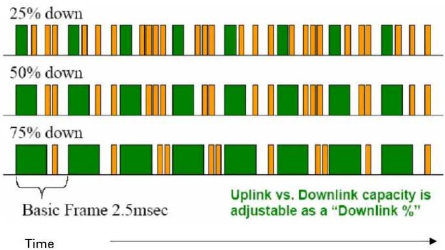
bar
| Time Segment | Downlink Capacity Change (%) | | ------------ | ---------------------------- | | Basic Frame 2.5msec | 2.5 | | Uplink vs. Downlink capacity adjustment as a 'Downlink %' | 3.5 |TDD frame parameters
The TDD burst duration varies depending on the following:
• Channel Bandwidth
- Cyclic Prefix
- Frame Period
• Frame configuration - Downlink Data
- Link operation - Dynamic Rate Adaptation
OFDM and channel bandwidth
The PMP/PTP 450 Platform Family transmits using Orthogonal Frequency Division Multiplexing (OFDM). This wideband signal consists of many equally spaced sub-carriers. Although each sub carrier is modulated at a low rate using conventional modulation schemes, the resultant data rate from the sub-carriers is high. OFDM works exceptionally over a Non-Line-of-Sight (NLoS) channel.
The channel bandwidth of the OFDM signal is configurable to one of the following values: 5, 7, 10, 15, 20, 30, and 40 MHz. Higher bandwidths provide greater link capacity at the expense of using more bandwidth. Systems configured for a narrower channel bandwidth provide better receiver sensitivity and can also be an appropriate choice in deployments where the amount of free spectrum is limited.

Note
The channel bandwidth must be configured to the same value at both ends of the link. Not all channel bandwidths are available in all regulatory bands.
Cyclic Prefix
OFDM technology uses a cyclic prefix, where a portion of the end of a symbol (slot) is repeated at the beginning of the symbol (slot) to allow multi-pathing to settle before receiving the desired data. A 1/16 cyclic prefix means that for every 16 bits of throughput data transmitted, an additional bit is used. For your convenience, the 450 Platform Family ODUs have been locked to a 1/16 CP.
Frame Period
The frame period or frame duration is the time between the beginning of a frame and the end of the frame. The 450 Platform Family supports two frame periods: 2.5 ms and 5 ms.
The 5ms frame period configuration provides higher throughput as a result of reduced frame overhead during transmission. In turn, the 2.5 ms frame period configuration affords reduced latency in the system, half of that introduced by the 5 ms frame configuration.
Frame configuration - Downlink Data
The percentage of frame assigned to transport downlink data. The downlink data specifies the percentage of the aggregate throughput for the downlink (frames transmitted from the AP/BHM to the subscriber). The configurable range is 15% to 85%.

Note
For all 450 platform APs, the maximum configurable range is 34% to 66% for 40 MHz with 5 ms frame.
Link operation - Dynamic Rate Adapt
The 450 Platform Family ODUs offer eight levels or speeds of operation - 2X MIMO-B and 1X MIMO-A (QPSK), 4X MIMO-B and 2X MIMO-A (16-QAM), 6x MIMO-B and 3X MIMO-A (64-QAM) and 8X MIMO-B and 4X MIMO-A (256-QAM). If received power varies due to distance between the AP/BHM and the SM/BHS or due to obstructions, or if interference affects the RF environment, the system automatically and dynamically adjusts the links to the best operation level.
The system chooses its modulation rate dynamically, based on an internal ARQ (Automatic Repeat reQuest) error control method. With ARQ, every data slot of every frame sent over the air (except downlink broadcast) is expected to be acknowledged by the receiver, and if acknowledgement is not received, the data is resent. The sending unit monitors these re-sends and adjusts the modulation rate accordingly. It is normal to have links that change levels of operation as the RF environment changes. Furthermore, the uplink or downlink portions of TDD duty cycle operate independently.
The various modulation levels used by 450 Platform Family are shown in Table 11.
Table 11 Modulation levels
| Rate | MIMO-B | MIMO-A |
| QPSK 2X MIMO-B 1X MIMO-A | ||
| 16-QAM | 4X MIMO-B | 2X MIMO-A |
| 64-QAM | 6X MIMO-B | 3X MIMO-A |
| 256-QAM | 8X MIMO-B | 4X MIMO-A |

Note
MIMO-A achieves half the throughput of MIMO-B but adds a combining diversity (gain) which enhances the link budget or availability.
Encryption
The 450 Platform Family supports optional encryption for data transmitted over the wireless link. The 450 Platform Family supports the following form of encryption for security of the wireless link:
AES (Advanced Encryption Standard): An over-the-air link encryption option that uses the Rijndael algorithm and 128-bit keys and 256-bit key size to establish a higher level of security than DES. AES products are certified as compliant with the Federal Information Processing Standards (FIPS 197) in the U.S.A.
The default setting on an AP is "Disabled".
MIMO
Multiple-Input Multiple-Output (MIMO) techniques provide protection against fading and increase the probability that the receiver decodes a usable signal. When the effects of MIMO are combined with those of OFDM techniques and a high link budget, there is a high probability of a robust connection over a non-line-of-sight path.
The sub-features that comprises the MIMO techniques utilized in the 450 Platform Family ODUs are:
- MIMO-A: This technique enables 450 Platform Family radio to use a scheme that optimizes coverage by transmitting the same data over both antennas. This redundancy improves the signal to noise ratio at the receiver making it more robust.
- MIMO-B: This technique provides the ability to double the throughput of a radio transmission under proper RF conditions. Different data streams are transmitted simultaneously on two different antennas.
MU-MIMO
Multiple-input multiple-output, or MIMO, is a range of technologies used to multiply the capacity of a wireless connection without requiring more spectrum.
Although traditional MIMO techniques are focused on increasing the bandwidth available between two wireless nodes, multi-user MIMO (MU-MIMO) applies these technologies to increase overall wireless network capacity by allowing an access point to communicate wirelessly with more than one wireless node at once.
A MU-MIMO access point features an array of antennas. When the AP decides to communicate with multiple nodes at the same time, it creates or receives multiple simultaneous beams between each node.
This is in contrast to a traditional wireless system, where two wireless nodes cannot communicate on the same channel to the same access point at the same time, without causing significant self-interference and degrading the overall wireless network performance.
A MU-MIMO access point estimates and measures what a transmission from each wireless node ‘sounds like’, by applying knowledge of the wireless path characteristics between the access point and node. Known as channel estimation, this process is of vital importance; without it, the access point cannot distinguish properly between wireless nodes, affecting performance.
Channel estimation is achieved at the access point in the downlink direction by sending a specific signal to a wireless node, which the node then reports back. The uplink channel estimates are made in a similar manner at the access point, by measuring the normal uplink communication to each node. These measurements between the access point and the nodes provide a measure of the wireless conditions and can be applied to other communications to/from the node and is known as channel sounding.
Channel estimation and sounding must be regularly repeated to ensure wireless network performance remains high; the speed at which a system is able to accurately estimate the channel has a large impact on performance.
Once channel estimation is completed for a wireless node, the MU-MIMO access point can electrically tune each antenna to provide the highest performance for that node. The access point uses beamforming to create a radio beam to that node which is tuned for optimum performance and avoids beams directed to other nodes, reducing interference and helping to improve overall wireless network capacity.
A MU-MIMO access point can communicate to multiple wireless nodes simultaneously using this process. As the majority of nodes are unable to make full use of the whole access point capacity at once, communicating with several nodes simultaneously can greatly improve the overall capacity achieved in the wireless network.
System management
This section introduces the 450 Platform Family management system, including the web interface, installation, configuration, alerts and upgrades.
Management agent
The 450 Platform Family radios are managed through an embedded management agent.
Management workstations, network management systems or PCs can be connected to this agent using the module's Ethernet port or over-the air (SM/BHS)
The management agent supports the following interfaces:
• Hypertext transfer protocol (HTTP)
• Hypertext transfer protocol secure (HTTPS)
- RADIUS authentication
- Simple network management protocol (SNMP) - v2c and v3
• Network time protocol (NTP)
• System logging (Syslog)
- Wireless Manager (WM) software
• Canopy Network Updater Tool (CNUT) software
- cnMaestro™
Web server
The 450 Platform Family management agent contains a web server. The web server supports access via the HTTP/HTTPS interface.
Web-based management offers a convenient way to manage the 450 Platform Family radios from a locally connected computer or from a network management workstation connected through a management network, without requiring any special management software. The web and SNMP are the interfaces supported for installation of 450 Platform Family radios and for the majority of configuration management tasks.
Web pages
The web-based management interfaces provide comprehensive web-based fault, configuration, performance and security management functions organized into the following groups:
Access Point or Backhaul Master:
- Home
- Configuration
- Statistics
- Tools
- Logs
- Accounts
- Quick Start
- Copyright
Subscriber Module or Backhaul Slave
- Home
- Configuration
- Statistics
- Tools
- Logs
- Accounts
- PDA
- Copyright
Identity-based user accounts
- When identity-based user accounts are configured, a security officer can define from one to four user accounts, each of which may have one of the four possible roles:
- ADMINISTRATOR, who has full read and write permissions. This is the level of the root and admin users, as well as any other administrator accounts that one of them creates.
- INSTALLER, who has permissions identical to those of ADMINISTRATOR except that the installer cannot add or delete users or change the password of any other user.
- TECHNICIAN, who has permissions to modify basic radio parameters and view informational web pages
- GUEST, who has no write permissions and only a limited view of General Status tab
- Admin, Installer and Tech accounts can be configured as READ-ONLY. This will allow the account to only see the items.
See Managing module access by passwords for detailed information on account permissions.
Remote Authentication Dial-in User Service (RADIUS)
The PMP configuration of 450 Platform Family includes support for RADIUS (Remote Authentication Dial In User Service) protocol functionality including:
- SM Authentication: Allows only known SMs onto the network (blocking “rogue” SMs), and can be configured to ensure SMs are connecting to a known network (preventing SMs from connecting to “rogue” APs). RADIUS authentication is used for SMs, but not used for APs.
- SM Configuration: Configures authenticated SMs with MIR (Maximum Information Rate), High Priority, and VLAN (Virtual LAN) parameters from the RADIUS server when a SM registers to an AP.
- User Authentication allows users to configure a separate User authentication server along with the SM authentication server. If firmware is upgraded while using this functionality and no User authentication servers are configured, then AP continues to use the SM authentication server for User authentication
- SM Accounting provides support for RADIUS accounting messages for usage-based billing. This accounting includes indications for subscriber session establishment, subscriber session disconnection, and bandwidth usage per session for each SM that connects to the AP.
- Centralized AP and SM user name and password management: Allows AP and SM usernames and access levels (Administrator, Installer, Technician and Read-Only) to be centrally administered in the RADIUS server instead of on each radio and tracks access events (logon/logoff) for each username on the RADIUS server. This accounting does not track and report specific configuration actions performed on radios or pull statistics such as bit counts from the radios. Such functions require an Element Management System (EMS) such as Cambium Wireless Manager. This accounting is not the ability to perform accounting functions on the subscriber/end user/customer account.
- Framed-IP-Address: Operators may use a RADIUS server to assign management IP addressing to SM modules. SNMP
The management agent supports fault and performance management by means of an SNMP interface. The management agent is compatible with SNMP v2c and SNMP v3 using Management Information Base (MIB) files which are available for download from the Cambium Networks Support website:
https://support.cambiumnetworks.com/files/ptp450
https://support.cambiumnetworks.com/files/pmp450
Network Time Protocol (NTP)
The clock supplies accurate date and time information to the system. It can be set to run with or without a connection to a network time server (NTP). It can be configured to display local time by setting the time zone and daylight saving in the Time web page.
If an NTP server connection is available, the clock can be set to synchronize with the server time at regular intervals. The 450 Platform Family radios may receive NTP data from a CMM4 module or an NTP server configured in the system's management network.
The Time Zone option is configurable on the AP's/BHM's Time Configuration page, and may be used to offset the received NTP time to match the operator's local time zone. When set on the AP/BHM, the offset is set for the entire sector (AP/BHSs is notified of the current Time Zone upon initial registration). If a Time Zone change is applied, the AP/BHSs are notified of the change in a best effort fashion, meaning some AP/BHSs may not pick up the change until the next re-registration. Time Zone changes are noted in the Event Log.
An AP/BHM which is receiving NTP date and time information from an NTP server or from a GPS synchronization source may be used as an NTP server. Any client which has IP connectivity to the BHM may request NTP date and time information from the AP/BHM. No additional configuration (other than the AP/BHM receiving valid NTP data) is required to use the AP/BHM as an NTP server.
cnMaestro™
cnMaestro™ is a cloud-based or on-premises platform specialized for secure, end-to-end network lifecycle management: inventory management, device onboarding, daily operations, and maintenance and is recommended for managing 450 Platform Family networks. The cnMaestro wireless network manager simplifies device management by offering full network visibility. Network operators can have a real-time view of their complete end-to-end network and perform a full suite of wireless network management functions to optimize system availability, maximize throughput, and meet emerging needs of business and residential customers. In addition, the cnMaestro wireless network manager collects and displays compliance with service level agreements.
To learn about cnMaestro™, please visit http://www.cambiumnetworks.com/products/software-tools/cnmaestro/
See Configuring cnMaestroTM Connectivity on 7-267 for details.
Wireless Manager (WM)
Cambium Networks Wireless Manager 4.0 is also used for managing 450 Platform Family networks. You can achieve better uptime through better visibility of your network with the Cambium Wireless Manager. This network management software tool offers breakthrough map-based visualization capabilities using embedded Google maps, and combined with advanced configuration, provisioning, alerting and reporting features you can control your entire outdoor wireless network including Point-to-Multipoint and Point-to-Point solutions as well as other SNMP enabled devices. With its powerful user interface, you can not only be able to control your network's access, distribution and backhaul layers, but can also have visibility to WLAN sites and be able to quickly launch indoor network management systems. Some key features of Wireless Manager are:
- Template-Based Configuration: With Wireless Manager's user-defined templates you can accelerate the process for the configuration of the devices you add to your network resulting in quicker and easier deployments. The template-based functionality provides an automated way to configure large numbers of network devices with just a few mouse clicks, and can be scheduled to occur at any time via Wireless Manager's Task Scheduler.
- Ultralight Thin Client: With the growing mobile workforce it is important to have access to the status of your network at any time. With Wireless Manager you can view the status and performance of your entire wireless network via a compact web interface accessible by your smart phone.
- Map-Based Visualization: Wireless Manager overlays sophisticated real-time information about your network elements onto building layouts and dynamic Google maps. Visuals can be scaled to view an entire city or building or a specific area, floor or link.
- High Availability Architecture Support: Wireless Manager offers a high availability option, providing a highly reliable and redundant network management solution that ensures you always have management access to your network.
- High Scalability: The enhanced Wireless Manager offers you server scalability with support for up to 10,000 nodes as well as support for distributed server architecture.
Cambium's Wireless Manager 4.0 available for download at:
https://www.cambiumnetworks.com/products/software-tools/wireless-manager/
Canopy Network Updater Tool (CNUT)
CNUT (Canopy Network Updater Tool) is the stand-alone software update tool for 450 Platform Family ODUs. The CNUT 4.11.2 should be used for 450 Platform Family ODUs.
The Canopy Network Updater Tool has the following features:
• Automatically discovers all network elements
- HTTP and HTTPS
- Executes UDP command that initiates and terminates the Auto-update mode within APs/BHMs. This command is both secure and convenient:
For security, the AP/BHM accepts this command from only the IP address that specified in the Configuration page of ODU.
- For convenience, Network Updater automatically sets this Configuration parameter in the AP/BHM to the IP address of the Network Updater server when the server performs any of the update commands.
- Allows you to choose among updating:
- Entire network.
o Only elements that you select. - Only network branches that you select.
- Provides a Script Engine that you can use with any script which:
- The user can define.
o Cambium supplies.
CNUT is available at:
https://www.cambiumnetworks.com/products/management/cambium-network-updater-tool/
Radio recovery mode
The 450 Platform Family recovery mode provides a means to recover from serious configuration errors including lost or forgotten passwords and unknown IP addresses.
The recovery procedure for 450m/450i/450b series and 450 series ODUs differ due to difference in hardware. This procedure for 450i/450m Series is known as Radio Recovery Console and for 450 Series is known as Default mode (or Default/Override Plug).
Radio Recovery Console - 450i, 450b and 450m Series
The Radio Recovery Console mode supports:
• Restoring factory default IP address 169.254.1.1 and password
- Boot with factory default Canopy system software settings
- Load previously installed SW images
See Radio Recovery Console- PMP/PTP 450i/450b and PMP 450m on page 9-35.
Default Mode (or Default Plug) - 450 Series
A default plug is available to provide access to a module whose password and/or IP address have been forgotten.
This plug allows the 450 Series ODUs to be accessed using IP address 169.254.1.1 and no password. During the override session, you can assign any new IP address and set either or both user passwords (display-only and/or full access) as well as make other parameter changes.
See Default Mode (or Default/Override Plug) - PMP/PTP 450 on page 9-38.
Chapter 2: System hardware
This chapter describes the hardware components of a 450 Platform link.
The following topics are described in this chapter:
- System Components on page 2-2 describes system components of PTP and PMP including its accessories
• Cabling on page 2-40 describes about various cables. - Lightning protection unit (LPU) and grounding kit on page 2-48 describes about lightning protection and grounding kit
- Antennas and antenna cabling on page 2-54 describes supported antennas and its accessories
• GPS synchronization on page 2-56 describes UGPS and CMM4. - Ordering the components on page 2-74 specifies Cambium part numbers for 450 Platform Family components
System Components
Point-to-Multipoint (PMP)
The PMP radio is a transceiver device. It is a connectorized or radiated outdoor unit containing all the radio, networking, and surge suppression electronics. It can be purchased as:
- Access Point Module (AP)
- Subscriber Module (SM)
PMP 450 Platform Family Integrated or Connectorized ODU
The PMP 450i Series and PMP 450 Series ODUs are supplied in Integrated or Connectorized configurations. The PMP 450m Series AP is supplied in Integrated configuration only.
See Table 2 PMP 450m Series hardware configurations on page 1-4
See Table 4 PMP/PTP 450i Series hardware configurations on page 1-6
See Table 6 PMP/PTP 450b Series hardware configurations on page 1-9
See Table 8 PMP/PTP 450 Series hardware configurations on page 1-11
Product variants
Table 12 PMP 450m Series variants
| Variant | Region | Antenna | Frequency Range | Channel Bandwidth | Max EIRP |
| 5 GHz PMP 450m AP | FCC | ||||
| RoW | 90° integrated sector array, 14x14 MIMO system, | 5150 – 5925 MHz | 5, 10, 15, 20, 30, 40 MHz | 48 dBm | |
| EU | |||||
| IC | |||||
| 3 GHz PMP 450m AP | Global | 90° integrated sector array, 8x8 MIMO system, | 3300 – 3900 MHz | 5, 7, 10, 15, 20, 30, 40 MHz | 52 dBm |
| Global (No Encryption) |
Table 13 PMP 450i Series variants
| Variant | Region | Antenna | Frequency Range | Channel Bandwidth | Max Tx Power |
| 900 MHz PMP 450i AP | FCC | Connectorized | 902 - 928 MHz | 5, 7, 10, 15, 20 MHz | 25 dBm |
| 3 GHz PMP 450i AP | FCC, RoW, Canada, RoW DES, Europe | Connectorized | 3300 – 3900 MHz | 5, 7, 10, 15, 20, 30, 40 MHz | 25 dBm |
| Integrated 16 dBi | |||||
| 5 GHz PMP 450i AP | FCC, RoW, Canada, RoW DES, Europe | Connectorized | 4900 – 5925 MHz | 5, 10, 15, 20, 30, 40 MHz | 27 dBm |
| Integrated 16 dBi 90 degree |
Table 14 PMP/PTP 450b Series variants
| Variant | Region | Antenna | Frequency Range | Channel Bandwidth | Max Tx Power |
| 5 GHz | FCC, RoW, Canada, RoW DES, Europe | 16 dBi integrated | 4900 – 5925 MHz | 5, 10, 15, 20, 30, 40 MHz | 27 dBm |
| PMP/PTP 450b SM | 23 dBi dish |

Note
The Transmit power is limited based on regional setting.
Table 15 PMP 450 Series variants
| Variant | Region | Antenna | Frequency Range | Channel Bandwidth | Max Tx Power |
| 900 MHz PMP 450 SM | FCC | Connectorized | 902 - 928 MHz | 5, 7, 10, 15, 20 MHz | 25 dBm |
| 2.4 GHz PMP 450 AP | FCC ISM | Connectorized | 2400 – 2483.5 MHz | 5, 10, 15, 20 MHz | 22 dBm |
| Integrated 18 dBi | |||||
| 2.4 GHz PMP 450 SM | FCC ISM | Connectorized | 2400 – 2483.5 MHz | 5, 10, 15, 20 MHz | 22 dBm |
| Integrated 7 dBi | |||||
| 3.5 GHz PMP 450 AP | FCC ISM | Connectorized | 3300 – 3600 MHz | 5, 7, 10, 15, 20, 30, 40 MHz | 25 dBm |
| Integrated 16 dBi | |||||
| 3.5 GHz PMP 450 SM | FCC ISM | Connectorized | 3300 – 3600 MHz | 5, 7, 10, 15, 20, 30, 40 MHz | 25 dBm |
| Integrated 8 dBi | |||||
| Integrated 19 dBi | |||||
| 3.65 GHz PMP 450 AP | FCC ISM | Connectorized | 3500 – 3850 MHz | 5, 7, 10, 15, 20, 30, 40 MHz | 25 dBm |
| Integrated 16 dBi | |||||
| 3.65 GHz PMP 450 SM | FCC ISM | Connectorized | 3500 – 3850 MHz | 5, 7, 10, 15, 20, 30, 40 MHz | 25 dBm |
| Integrated 8 dBi | |||||
| Integrated 19 dBi | |||||
| 5.4/5.8 GHz PMP 450 AP | FCC, RoW, RoW DES | Connectorized | 5470 – 5875 MHz | 5, 10, 15, 20, 30, 40 MHz (5, 15 and 30 MHz not available in DFS regions) | 22 dBm |
| Integrated 17 dBi | |||||
| 5.4/5.8 GHz PMP 450 SM | FCC, ROW, RoW DES | Connectorized | 5470 – 5875 MHz | 5, 10, 15, 20, 30, 40 MHz (5, 15 and 30 MHz not available in DFS regions) | 22 dBm |
| Integrated 9 dBi | |||||
| Integrated 25 dBi |

Note
The Transmit power is limited based on regional setting.
Backhaul (PTP)
The Backhaul radio is a transceiver device. It is a connectorized or integrated outdoor unit containing all the radio, networking, and surge suppression electronics. It can be configured as:
- Backhaul Master (BHM)
- Backhaul Slave (BHS)
PTP 450 Platform Family Integrated or Connectorized ODU
See Table 4 PMP/PTP 450i Series hardware configurations on page 1-6
See Table 8 PMP/PTP 450 Series hardware configurations on page 1-11
Product variants
Table 16 PTP 450i Series variants
| Variant | Region | Antenna | Frequency Range | Channel Bandwidth | Max Tx Power | Notes |
| 3 GHz PTP 450i | FCC, RoW, Canada, Row DES, Europe | Connectorized | 3300 - 3900 MHz | 5, 7, 10, 15, 20, 30, 40 MHz | 25 dBm | Transmit power limited based on regional setting |
| Integrated 23 dBi | ||||||
| 5 GHz PTP 450i | FCC, RoW, Canada, Row DES, Europe | Connectorized | 4900 – 5925 MHz | 5, 10, 15, 20, 30, 40 MHz | 27 dBm | Transmit power limited based on regional setting |
| Integrated 23 dBi |
Table 17 PTP 450 Series variants
| Variant | Region | Antenna | Frequency Range | Channel Bandwidth | Max Tx Power |
| 900 MHz PTP 450 BH | FCC Connectorized | 902 – 928 MHz | 5, 7, 10, 15, 20 MHz | 25 dBm | |
| 3.5 GHz PTP 450 BH | ROW | Connectorized | 3300 – 3600 MHz | 5, 7, 10, 15, 20, 30, 40 MHz | 25 dBm |
| Integrated 16 dBi | |||||
| Integrated 19 dBi | |||||
| 3.65 GHz PTP 450 BH | ROW | Connectorized | 3500 – 3850 MHz | 5, 7, 10, 15, 20, 30, 40 MHz | 25 dBm |
| Integrated 16 dBi | |||||
| Integrated 19 dBi | |||||
| 5.4/5.8 GHz PTP 450 BH | FCC, RoW, RoW DES | Connectorized | 5470 – 5875 MHz | 5, 10, 15, 20, 30, 40 MHz | 22 dBm |
| Integrated 9 dBi | |||||
| Integrated 25 dBi | |||||

Note
The Transmit power is limited based on regional setting.
450 Platform Family interfaces
PMP 450m Series interfaces - AP - 3GHz
The 3 GHz 450m Series AP interfaces is illustrated below.
Figure 3 3GHz PMP 450m Series interfaces

Table 18 PMP 3GHz 450m Series AP interface descriptions and cabling
| Interface | Function | Cabling |
| PSU | DC power input, 40 V - 60 V, plus Cambium Sync-over-power | 4-core (2 twisted pairs) |
| Ethernet | 10/100/1000Base-T Ethernet, plus Cambium Sync-over-data | CAT5e |
| AUX | 10/100Base-T Ethernet with PoE out | CAT5e |
| UGPS synchronization port | ||
| Audio tones | ||
| SFP 1 | SFP module. Currently not used when operating a 3GHz 450m as an AP. For future use when operating 3GHz 450m as an LTE RRH. | Fibre or copper |
| SFP 2 | SFP module (single or dual). This is the module currently used for 3GHz 450m AP. | Fibre or copper |
| Ground Lugs | For grounding the unit | 10 AWG copper wire |
PMP 450m Series interfaces - AP - 5 GHz
The 5 GHz 450m Series AP interfaces is illustrated below.
Figure 4 5GHz PMP 450m Series interfaces


natural_image
Exterior view of a mechanical or electrical component with a vertical rod and metal bracket (no visible text or symbols)Table 19 PMP 5 GHz 450m Series AP interface descriptions and cabling
| Interface | Function | Cabling |
| PSU/Ethernet | Power-over-Ethernet, Ethernet communications (management and data), CMM5 sync-over-power synchronization input | RJ45 CableSee Table 106 on page 5-12 |
| Aux/Sync GPS synchronization input and output, UGPS power output | RJ 45 CableSee Table 107 on page 5-12 | |
| SFP Read Ethernet communications (management and data) | ||
| Ground Lugs | For grounding the unit | 10 AWG copper wire |
 | NoteFor PMP 450m AP, the Sync-Over-Power is supported with CMM5 only.For PMP 450m AP, the Sync-Over-Power will not work with CMM4 like PMP 450/450i Series. | |
 | NoteSFP kits (Single Mode Optical SFP Interface per ODU (part number C000065L008A),Multi-mode Optical SFP Interface per ODU (part number C000065L009A), and 2.5GBASE-T Copper SFP Interface per ODU (part number C000065L011A)) are required for SFP port connectivity. | |
PMP/PTP 450i Series interfaces - AP/SM/BH
The AP/SM/BH interfaces are illustrated below.
Figure 5 PMP/PTP 450i interfaces

Table 20 PMP/PTP 450i Series - AP/SM/BH interface descriptions and cabling
| Interface | Function | Cabling |
| PSU/Ethernet | Power-over-Ethernet, Ethernet communications (management and data), CMM sync-over-power synchronization input | RJ45 CableSee Table 106 on page 5-12 |
| Aux/Sync | GPS synchronization input and output, UGPS power output | RJ 45 CableSee Table 107 on page 5-12 |
| Audio tones | ||
| Data | ||
| RF Port A | Vertical RF connection to antenna | 50 ohm RF cable, N-type |
| RF Port B | Horizontal RF connection to antenna | 50 ohm RF cable, N-type |
| Ground Lugs | For grounding the unit | 10 AWG copper wire |

Note
If the Aux port will be used, a second Ethernet Gland will need to be ordered (Part Number: N000065L033A).
PMP/PTP 450b Mid-Gain Series interfaces - SM
The PMP/PTP 450b Series - SM interfaces are illustrated below.
Figure 6 PMP 450b Mid-Gain Series - SM interfaces

natural_image
Two white electronic components with internal connectors and a circular button, one labeled 'RMP 450' (no other text or symbols visible)
natural_image
White electronic device casing with internal components and blue indicator lines (no visible text or symbols)Table 21 PMP/PTP 450b Series - SM (Mid-Gain) interface descriptions and cabling
| Interface | PSU/Ethernet Port | |
| Function | Cabling | |
| PSU/Ethernet | Audio AUX PortPower-over-Ethernet, Ethernet communications (management and data) | RJ45 Cable |
| Audio AUX Port | 3.5 mm audio jack for alignment tone | Standard 3.5 mm TRRS headphones |
PMP/PTP 450b High Gain Series interfaces - SM
The PMP 450b Series - SM interfaces are illustrated below.
Figure 7 PMP 450b Series - SM interfaces (High Gain)

natural_image
Two white satellite dishes with internal components, shown from different angles (no text or symbols visible)Table 22 PMP/PTP 450b Series - SM (High Gain) interface descriptions and cabling
| Interface | Function | Cabling |
| PSU/Ethernet | Power-over-Ethernet, Ethernet communications (management and data) | RJ45 Cable |
| Audio AUX Port | 3.5 mm audio jack for alignment tone | Standard 3.5 mm TRRS headphones |
PMP/PTP 450 Series interfaces - AP
The PMP 450 Series - AP interfaces are illustrated below.
Figure 8 PMP/PTP 450 Series - AP interfaces

Table 23 PMP/PTP 450 Series - AP interface descriptions and cabling - 2.4 GHz and 5 GHz
| Interface | Function | Cabling | |
| PSU/Ethernet | Power-over-Ethernet, Ethernet communications (management and data) | RJ45 Cable | |
| Sync/Default | GPS synchronization signaling, provides power to UGPS module. Default plug port. | RJ11 cable, default plug. | |
| RF Port A | 2.4 GHz | -45 degree RF connection to AP antenna | 50 ohm RF cable, N-type |
| 5 GHz | Vertical RF connection to AP antenna | ||
| RF Port B | 2.4 GHz | +45 degree RF connection to AP antenna | 50 ohm RF cable, N-type |
| 5 GHz | Horizontal RF connection to AP antenna | ||
| Ground Lugs | For grounding the unit | 10 AWG copper wire | |
PMP/PTP 450 Series interfaces - SM/BH
The PMP 450 Series SM/BH interfaces are illustrated below.
Figure 9 PMP/PTP 450 Series - SM/BH interfaces
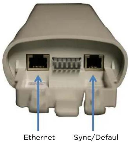
Figure 10 PMP/PTP 450 Series - SM/BH Connectorized interfaces


Note
As per Underwriters Laboratory (UL) guidelines, the Ground Lug on the radiated SM is not required.
Figure 11 PMP 450d Series - SM Integrated Dish

Figure 12 PMP 450 Series - SM 3 GHz Integrated

natural_image
White industrial air purifier mounted on a flat panel, no visible text or symbolsFigure 13 PTP 450 Series - BHM/BHS

ATEX/HAZLOC variants
PTP/PMP 450i series products are available in ATEX/Hazloc variants for operation in locations where explosive gas hazards exist, as defined by Hazloc (USA) and ATEX (Europe). ATEX/HAZLOC variants are similar to the standard product except that:
• ODUs are supplied with the Full capacity license
• The frequency range is restricted to 4940 MHz to 5850 MHz
- The maximum EIRP generated by ODU is restricted to comply with the ATEX and HAZLOC standards
In order to meet specific radio regulations in the USA, Canada and the EU, Cambium supplies products approved for USA, Canada, EU and the rest of the world under different models and part numbers. These models and part numbers are shown in Table 68 and Table 69.
Diagnostic LEDs
The diagnostic LEDs of 450 Platform Family ODUs are as shown below.

Note
The colors shown in the diagram may differ from the actual color displayed by the AP/BHM, depending on its current status.
AP/BHM LEDs
The diagnostic LEDs report the information about the status of the AP/BHM.
Figure 14 AP/BHM diagnostic LEDs, viewed from unit front
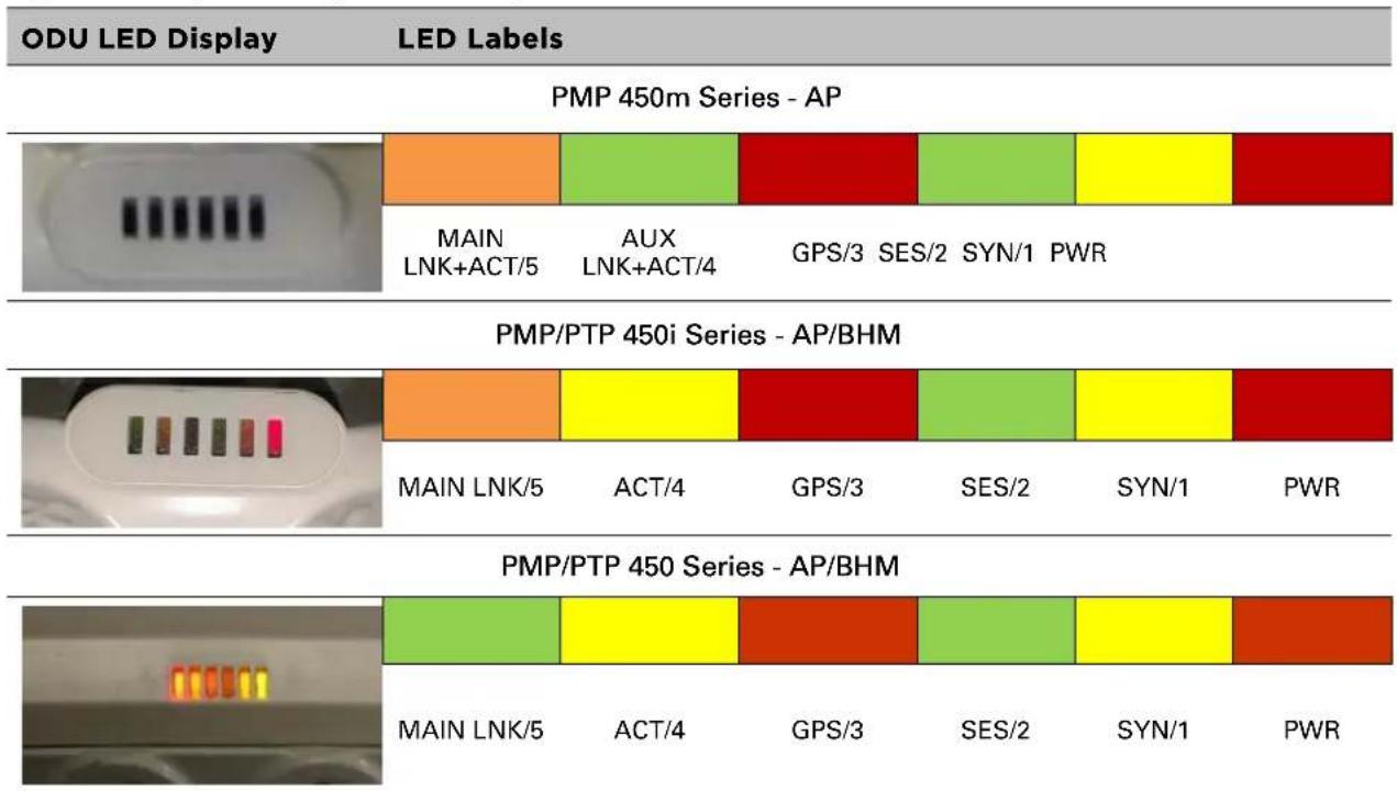
Table 24 AP/BHM LED descriptions
| LED | Color when active | Status information provided | Notes |
| PWR Red | DC power | Always lit after 10-20 seconds of power on. | |
| SYN/1 Yellow | Presence of sync | - | |
| SES/2 Green | Unused - | ||
| GPS/3 | Red | Pulse of sync | Lit when the AP/BHM is getting a sync pulse from a GPS source goes along with SYN/1 |
| ACT/4 | For 450 and 450i Series Yellow | Presence of data activity on the Ethernet link | Flashes during data transfer.Frequency of flash is not a diagnostic indication. |
| AUX LNK + ACT/4 | For 450m Series Red/ Green (bi-colored for 10/100) | Aux port link speed and activity | Flashes to indicate Ethernet activity on Aux port. Indicates speed based on the following colors:10Base-T : Red100Base-T : Green |
| MAIN LNK/5 | For 450i Series Red/ Green/Orange (bi-colored for 10/100/1000) | Activity on Main port link | Continuously lit when link is present.Indicates speed based on the following colors:10Base-T : Red100Base-T : Green1000Base-T : Orange |
| For 450 AP Orange/Green/Yellow (10/100/1000) | Ethernet link | Continuously lit when link is present.10Base-T : Orange100Base-T : Green1000Base-T : Yellow | |
| For 450 BHM Green | Continuously lit when link is present.10Base-T : Green100Base-T : Green | ||
| MAIN LNK + ACT/5 | For 450m Series Red/ Green/Orange (bi-colored for 10/100/1000) | Main port link speed and activity | Flashes to indicate data transfer speed and activity. |
SM/BHS LEDs
The SM/BHS LEDs provide different status of radio based on the operating modes. A SM/BHS in “operating” mode registers and passes traffic normally. A SM/BHS in “aiming” mode does not register or pass the traffic, but displays (via LED panel) the strength of received radio signals (based on radio channel selected via Tools -> Alignment).
Figure 15 AP/BH diagnostic LEDs, viewed from unit front
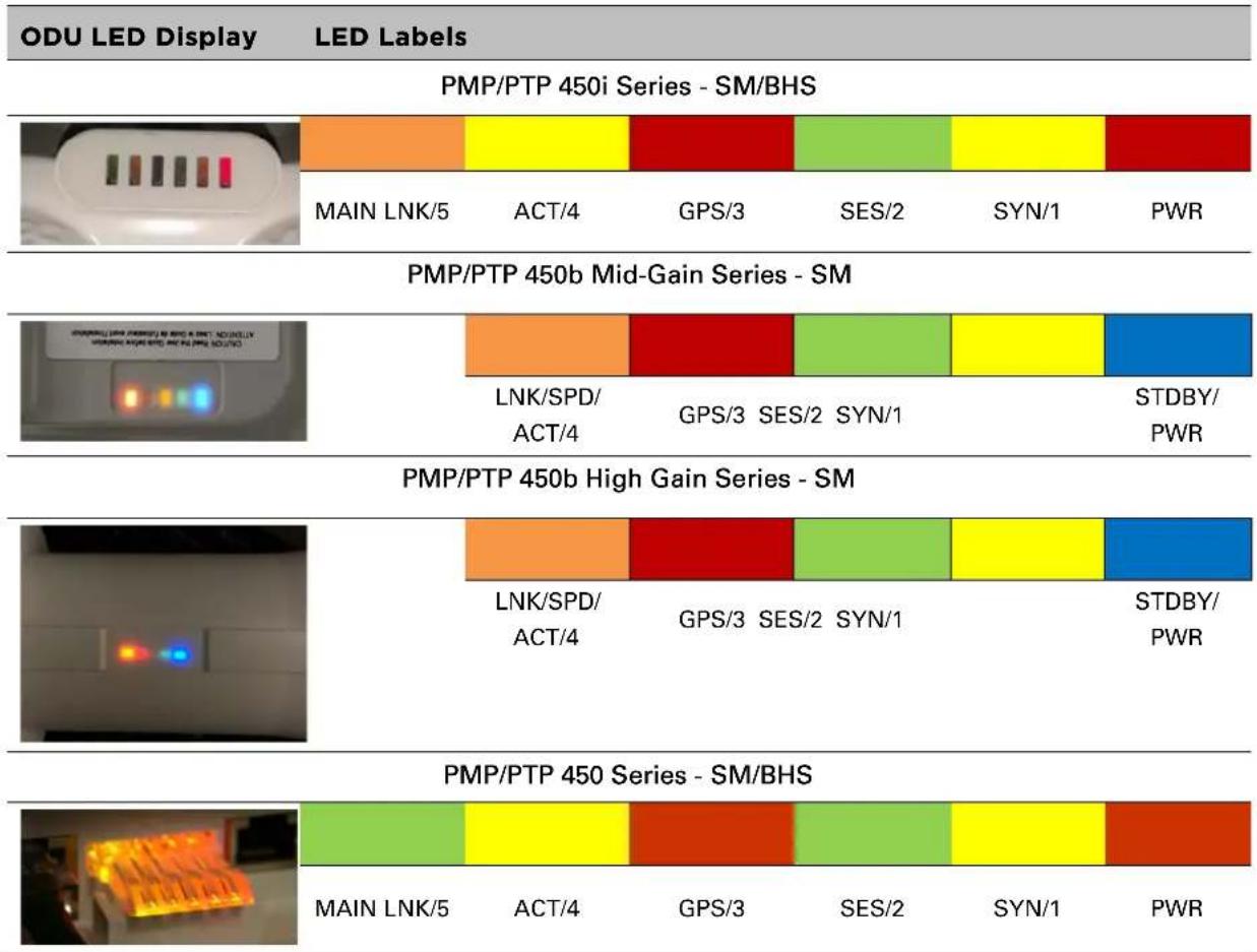
Table 25 SM/BHS LED descriptions
| Status information provided | ||||
| LED | Color when active | SM / BHS in “Operating” Mode | SM / BHS in “Aiming” Mode | Notes |
| PWR Red | DC power DC power | Always lit after 10-20 seconds of power on. | ||
| STDBY/PWR | Yellow/Blue | Flashes Yellow during boot-up.Flashes Blue when operating. | ||
| SYN/1 | Yellow | Presence of sync | These three LEDs act as a bar graph to indicate the relative quality of alignment. As power level improves during alignment, more of these LEDs are lit. | Lit when SM/BHS is in sync with an AP/BHM. |
| SES/2 | Green | Session Indicator | Lit when SM/BHS is in session. | |
| GPS/3 | Red | Unused | Unused | |
| ACT/4 | Yellow | Presence of data activity on the Ethernet link | Presence of data activity on the Ethernet link | Flashes during data transfer. Frequency of flash is not a diagnostic indication. |
| LNK/SPD/ACT/4 | For 450b SeriesRed/Green/orange(10/100/1000) | Ethernet Link Ethernet Link | Flashes during data transfer. Frequency of flash is not a diagnostic indication.10Base-T : Red100Base-T : Green1000Base-T : Orange | |
| MAINLNK/5 | For 450i SeriesRed/ Green/Orange(bi-colored for 10/100/1000) | Ethernet link Ethernet link | Flashes during data transfer.10Base-T : Red100Base-T : Green1000Base-T : Orange | |
| For 450SeriesGreen | Ethernet link Ethernet link | Continuously lit when link is present. | ||
Operating Mode
- Scanning: If the SM/BHS is not registered to AP/BHM, then these three LEDs cycle on and off from left to right (SYN/1, SES/2 and GPS/3).
- Ethernet Link:
For 450m AP, the MAIN LNK + ACT/5 LED is active when the Main port link is present and the AUX LNK + ACT/4 LED is active when the Aux port link is present.
- For 450/450i AP/BHM, the MAIN LNK/5 LED is lit continuously when the link is present.
- For 450/450i SM/BHS, the MAIN LNK/5 LED is lit continuously when the link is present.
- Data Transfer:
For 450m AP, the MAIN LNK + ACT/5 LED flashes to indicate data transfer speed and activity on the Main port and the AUX LNK + ACT/4 LED flashes to indicate data transfer speed and activity on the Aux port.
- For 450/450i AP/BHM, the ACT/4 LED flashes during data transfer.
- For 450/450i SM/BHS, the ACT/4 LED flashes during data transfer.
- For 450b SM, the LNK/SPD/ACT/4 LED flashes during data transfer.
Aiming Mode
The 3 LEDs (SYN/1, SES/2, and GPS/3) are turned into a 3-position bar graph. The more LEDs that are lit, the better the received power the module is seeing. The colors of the LEDs have no particular meaning other than to assist is distinguishing one position from the next.
Power supply options
The 450 Platform Family ODUs are powered over its Main Ethernet cable using Power Over Ethernet (POE). The power injector is connected to the ODU and network terminating equipment using Cat5e cable with RJ45 connectors.
Power supply - PMP 450m Series
The PMP 450m Series - 5 GHz AP supports powering from AC+DC Enhanced Power Injector (see AC+DC Enhanced Power Injector on page 2-26)
PSU part numbers
Table 26 PSU part numbers for PMP 450m AP (5/3 GHz)
| AP Model | Cambium description | Cambium part number |
| 5 GHz | AC+DC Enhanced Power Injector | C000065L002C |
| 3 GHz | Power Supply, AC, 54V 240W | N000000L054B |
Power supply - PMP/PTP 450i Series
The PMP/PTP 450i Series supports powering from the following powering sources:
• Power Supply, 60 W, 56 V with 1000BASE-T or GigE
• AC+DC Enhanced Power Injector
• Power over Ethernet midspan, 60 W, -48 VDC Input
• CMM4 with external 56 V power supply and CMM4 to 450i Series ODU cable (Dongle)
- IEEE802.3at power injector

Note
The 900 MHz SM is based off of the 450 Series, please see Power supply - PMP/PTP 450 Series on page 2-30.

Warning
Always use an appropriately rated and approved AC supply cord-set in accordance with the regulations of the country of use.

Warning
The PMP 450 Ruggedized High Gain Integrated Subscriber Module (Cambium part numbers C035045C014A and C036045C014A), while encapsulated in a 450i-type enclosure, contains 450 circuitry which must be powered via 30 VDC. Powering these SMs with a 56 VDC will damage the device.
Please refer to Cabling on Page 2-40 for details on maximum cable lengths between power injector and PMP/PTP 450i.
PSU part numbers
Table 27 PSU part numbers for PMP/PTP 450i Series
| Cambium description | Cambium part number |
| Power supply, 60 W, 56 V with Gbps support | N000065L001B |
| AC+DC Enhanced Power Injector | C000065L002C |
| Line Cord, Fig 8 - US | N000065L003A |
| Line Cord, Fig 8 - UK | N000065L004A |
| Line Cord, Fig 8 - EU | N000065L005A |
| Power over Ethernet midspan, 60 W, -48 VDC Input | N000000L036A |
| Power supply, 30 W, 56 V - Gbps support | N000000L034A |
AC Power Injector N000065L001B
The AC Power Injector interfaces are shown in Figure 16 and described in Table 28.
Figure 16 AC Power Injector interfaces
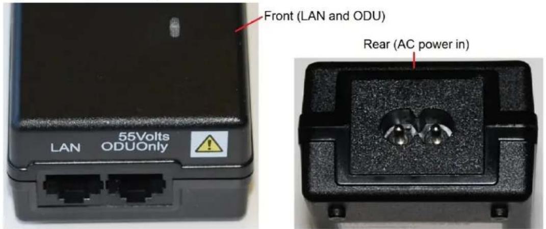
Table 28 AC Power Injector interface functions
| Interface | Function |
| AC power in | AC power input (main supply) |
| ODU RJ45 socket for connecting Cat5e cable to ODU | |
| LAN RJ45 socket for connecting Cat5e cable to network | |
| Power (green) LED | Power supply detection |
AC+DC Enhanced Power Injector C000065L002C
The AC+DC Enhanced Power Injector interfaces are shown in Figure 17 and described in Table 29.
Figure 17 AC+DC Enhanced Power Injector interfaces
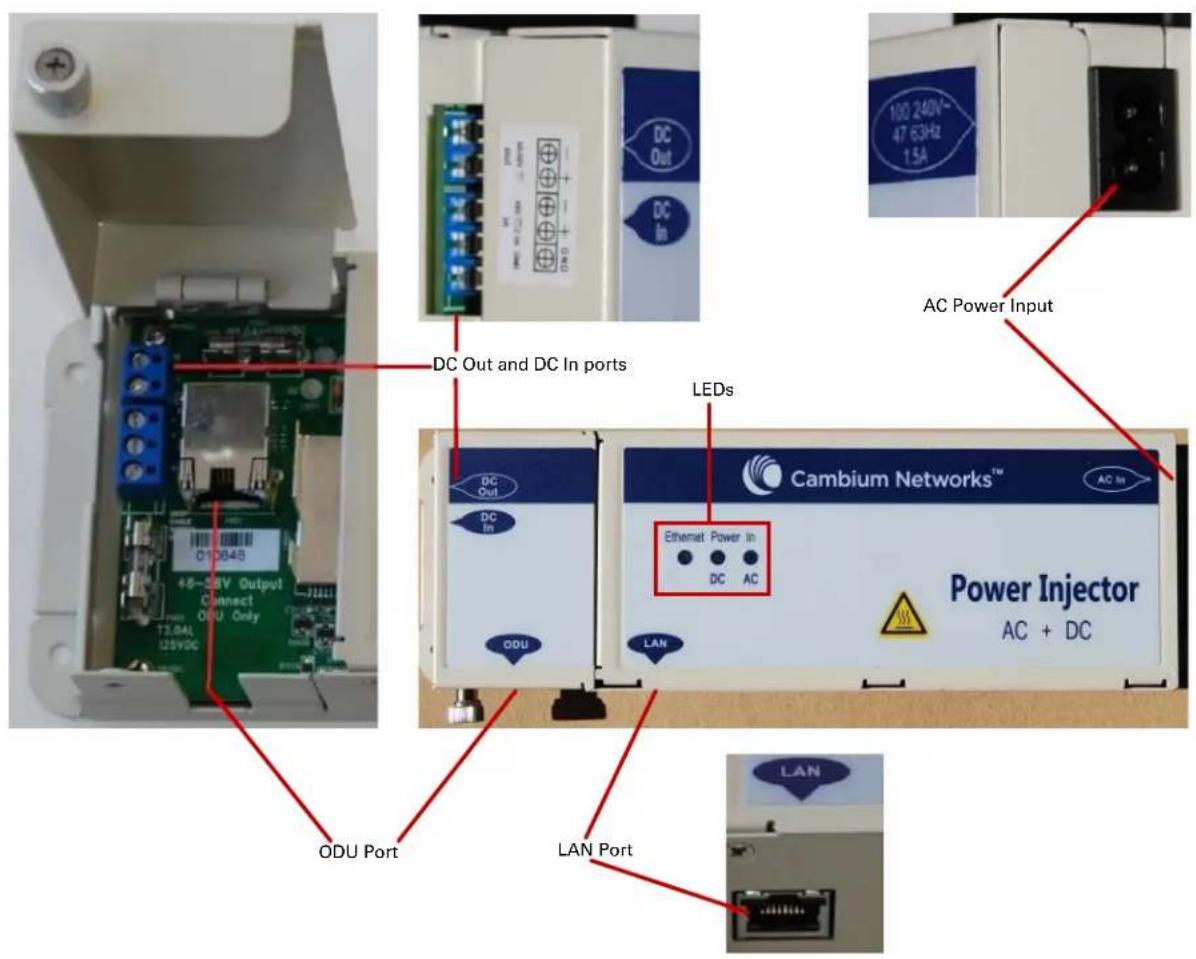
Table 29 AC+DC Enhanced Power Injector interface functions
| Interface | Function |
| 100-240V 47-63Hz 1.7A | AC power input (main supply) |
| DC In Alternative DC power supply input | |
| DC Out | DC power output to a second PSU (for power supply redundancy) or to a NIDU |
| ODU RJ45 socket for connecting Cat5e cable to ODU | |
| LAN RJ45 socket for connecting Cat5e cable to network | |
| Power - AC (green) LED | Indicates power is applied at the AC power input |
| Power - DC (green) LED | Indicates power is applied at the DC In port |
| Ethernet (yellow) LED | Detects Ethernet traffic and it is used with PTP650 and PTP700 families only. It does not operate with the 450 platform products. |

Note
The earlier power injector models only had a single power LED that combined the AC+DC indications.
-48 VDC Power Injector N000000L036A
The DC Power Injector interfaces are shown in Figure 18 and described in Table 30.
Figure 18 -48 V DC Power Injector interfaces
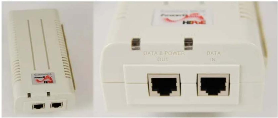
natural_image
Close-up of two white wireless network devices with power connectors and I/O ports, no visible text or symbols on the devices themselves.Table 30 -48V DC Power Injector interfaces
| Interface | Function |
| DC input 36 to 60V, 2A | |
| RJ 45 Sockets Two (Data In and Data & Power Out) | |
| LEDs Two (AC and Port) | |
Power supply - PMP/PTP 450b Series
The PMP/PTP 450b Series support powering from the following powering sources:
• Gigabit Enet Capable Power Supply - 20 to 32 V DC, 15W
• CMM4 with external 29 V power supply
Figure 19 -20 to 32 VDC Power Injector interfaces

Table 31 -Power Injector interfaces
| Interface | Function |
| PSU/Ethernet | 20 to 32 VDC, 2A |
PSU part numbers
Table 32 PSU part numbers for PMP/PTP 450b SM
| Cambium description | Cambium part number |
| Gigabit Enet Capable Power Supply - 20 - 32VDC, 15W | N000900L001C |
Power supply - PMP/PTP 450 Series
The PMP/PTP 450 Series support powering from the following powering sources:
• Gigabit Enet Capable Power Supply - 30 VDC, 15W
• CMM4 with external 29 V power supply

Warning
The PMP 450 Ruggedized High Gain Integrated Subscriber Module (Cambium part numbers C035045C014A and C036045C014A), while encapsulated in a 450i-type enclosure, contains 450 circuitry which must be powered via 30VDC. Powering these SMs with a 56 VDC will damage the device.
PSU part numbers
Table 33 PSU part numbers for PMP/PTP 450 Series
| Cambium description | Cambium part number |
| Gigabit Enet Capable Power Supply - 30VDC, 15W | N000900L001C |
| Cable, UL Power Supply Cord Set, US | N000900L007A |
| Cable, UL Power Supply Cord Set, EU | N000900L008A |
| Cable, UL Power Supply Cord Set, UK | N000900L009A |
| Cable, UL Power Supply Cord Set, Brazil | N000900L010A |
Gigabit Enet Capable Power Supply
The Gigabit Enet Capable power supply interfaces are described in Table 34. This power supply requires procurement of an AC line cord that connects the outlet of the same (using IEC-60320 Type 5 connector). A list of available power supply cord options from Cambium Networks are given in Table 33.
Table 34 -Gigabit Enet Capable power supply
| Interface | Function |
| AC Input | 90-264 VAC, 0.5A rms @120VAC/ 0.25A rms @240VAC, 47 to 63 Hz |
| DC Output | 30.0 Vdc +/-5%, 15W, 500 mA max |
| RJ 45 Sockets Two (Data In and Data & Power Out) | |
| LEDs Green, :LED Intensity determined by Level 5 efficiency | |
Figure 20 Gigabit Enet Capable power supply

natural_image
Close-up of a black USB device with cable, its top-right view, and its three-pin plug (no visible text or symbols)ODU mounting brackets & accessories
The list of supported brackets is provided in Table 35.
- The "Tilt bracket assembly" is the recommended bracket for the AP, SM or BH integrated units.
- The "Mounting Bracket (Connectorized)" can be used where a low profile and ease of assembly of Connectorized AP, SM or BH is required.
- The "Mounting Bracket (Integrated)" provide a wider range of adjustment for AP, SM and BH integrated devices.
Table 35 Accessories part numbers
| Cambium description | Cambium part number |
| Mounting brackets | |
| Tilt Bracket Assembly N000045L002A | |
| Mounting Bracket (Integrated) N000065L031A | |
| Mounting Bracket (Connectorized) | N000065L032A |
| Miscellaneous | |
| Ethernet cable adapter for CMM4 (Dongle) | N000045L001A |
| RJ-45 Gland Spare - PG16 style (QTY 10) | N000065L033A |
| Blanking Plug Pack (Qty 10) N000065L036A | |
Lightning protection
The 450 Platform Family supports the lightning protection units listed in Table 36.
The LPU offers the highest level of protection and is the recommended device. Where low cost deployment is essential, for example for SM in residential application, the Gigabit Surge Suppressor may be used instead.
Table 36 Lightning protection part numbers
| Cambium description | Cambium part number |
| 450 Series (Including 450b and 450d) | |
| Surge Suppressor (30 VDC) | 600SSH |
| 450i and 450m Series | |
| LPU and Grounding Kit (1 kit per ODU) | C000065L007B |
| Gigabit Surge Suppressor (56 VDC) | C000000L033A |
| DC LPU and Grounding Kit | C000000L114A |
ODU interfaces
PMP 450m Series 5 GHz AP
These interfaces are described in Table 39.
Figure 21 PMP 450m Series - AP rear interfaces

Table 37 PMP 450m Series - AP rear interfaces
| Port name | Connector | Interface | Description |
| PSU (Main) | RJ45 | PoE input | Power over Ethernet (PoE). |
| 10/100/1000 BaseT Ethernet | Data | ||
| Aux | RJ45 | 10/100 BaseT Ethernet | Data |
| PoE output Standard IEEE802.3at PoE. | |||
| Sync input/output Connection and powering of UGPS Sync input | |||
| SFP | SFP | 2.5 Gbps Fiber Ethernet and 1 Gbps Copper | Data and Management Services.Plug-in SFP module must be purchased separately. |
| Ground Lugs | 10 AWG copper wire | For grounding the unit | |
PMP 450m Series 3GHz AP
These interfaces are described in Table 38.
Figure 22 PMP 450m 3GHz - AP rear interfaces

Table 38 PMP 450m 3GHz - AP rear interfaces
| Port name | Connector | Interface | Description |
| PSU 4-pin | DC power input | DC power input, 40 V - 60 V, plus Cambium Sync-over-power | |
| Main | RJ45 | Ethernet | 10/100/1000Base-T Ethernet, plus Cambium Sync-over-data |
| Aux | RJ45 | EthernetSynchronization | 10/100Base-T Ethernet with PoE outUGPS synchronization port |
| Alignment Audio tones | |||
| SFP 1 | SFP | Ethernet | SFP module |
| SFP 2 | SFP | Ethernet | SFP module (single or dual) |
| Ground Lugs | 10 AWG copper wire For grounding the unit | ||
PMP/PTP 450i
The Ethernet and Sync/AUX ports are on the rear of the integrated and connectorized ODUs (Figure 23). These interfaces are described in Table 39.
Figure 23 PMP/PTP 450i Series - ODU rear interfaces
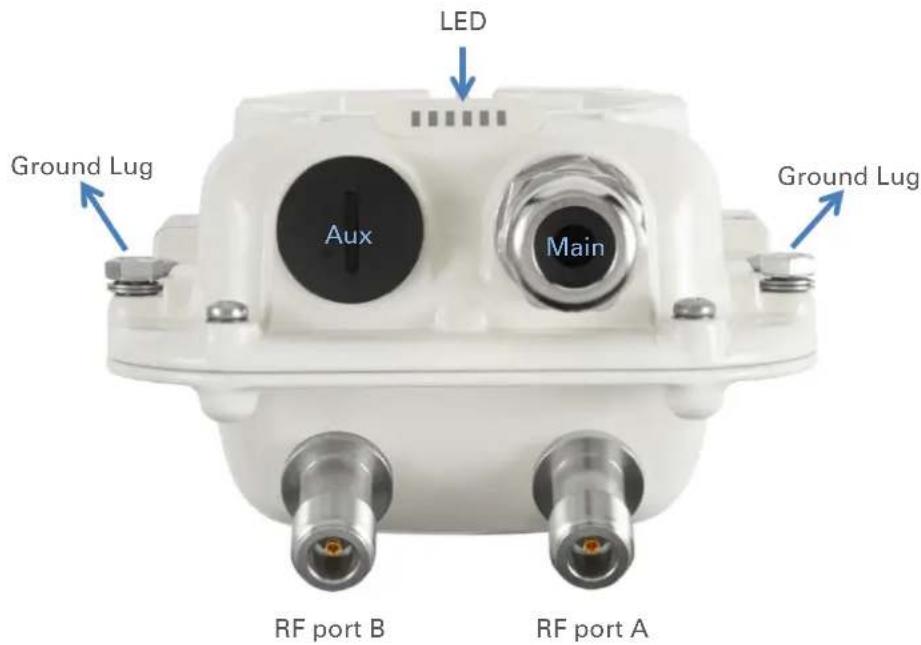
Table 39 PMP/PTP 450i Series - ODU rear interfaces
| Port name | Connector | Interface | Description |
| Main PSU | RJ45 | PoE input | Power over Ethernet (PoE). |
| 10/100/1000BASE-T Ethernet | Data | ||
| Sync/AUX | RJ45 | 10/100/1000BASE-T Ethernet | Data (see Note below) |
| PoE output Standard IEEE802.3at PoE. | |||
| Sync input/output | Connection and powering of UGPS Sync input | ||
The front of the connectorized ODU (Figure 24 PMP/PTP 450i Series - Connectorized ODU antenna interfaces) provides N type female connectors for RF cable interfaces to antennas with ports A and B for vertical and horizontal polarization respectively.
Figure 24 PMP/PTP 450i Series - Connectorized ODU antenna interfaces

natural_image
Close-up of a white electrical outlet with metallic connectors and a triangular component (no visible text or symbols)PMP/PTP 450b Mid-Gain SM
The Ethernet and AUX ports are on the rear of the integrated and connectorized ODUs (Figure 25). These interfaces are described in Table 40.
Figure 25 PMP/PTP 450b Mid-Gain SM - ODU rear interfaces
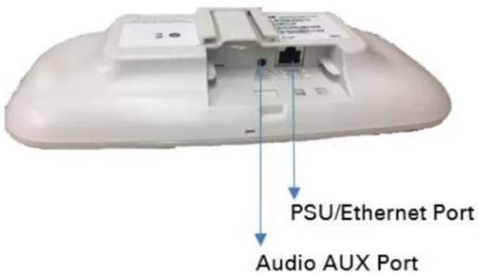
Table 40 PMP/PTP 450b Mid-Gain SM - ODU rear interfaces
| Port name | Connector | Interface | Description |
| PSU/Ethernet Port | RJ45 | PoE input | Power over Ethernet (PoE). |
| 10/100/1000BASE-T Ethernet | Data | ||
| Audio AUX Port | Standard 3.5 mm headphones | Alignment tone input | 3.5 mm audio jack for alignment tone |
PMP/PTP 450b High Gain SM
The Ethernet and AUX ports are on the rear of the integrated and connectorized ODUs (Figure 25). These interfaces are described in Table 40.
Figure 26 PMP/PTP 450b High Gain SM - ODU rear interfaces
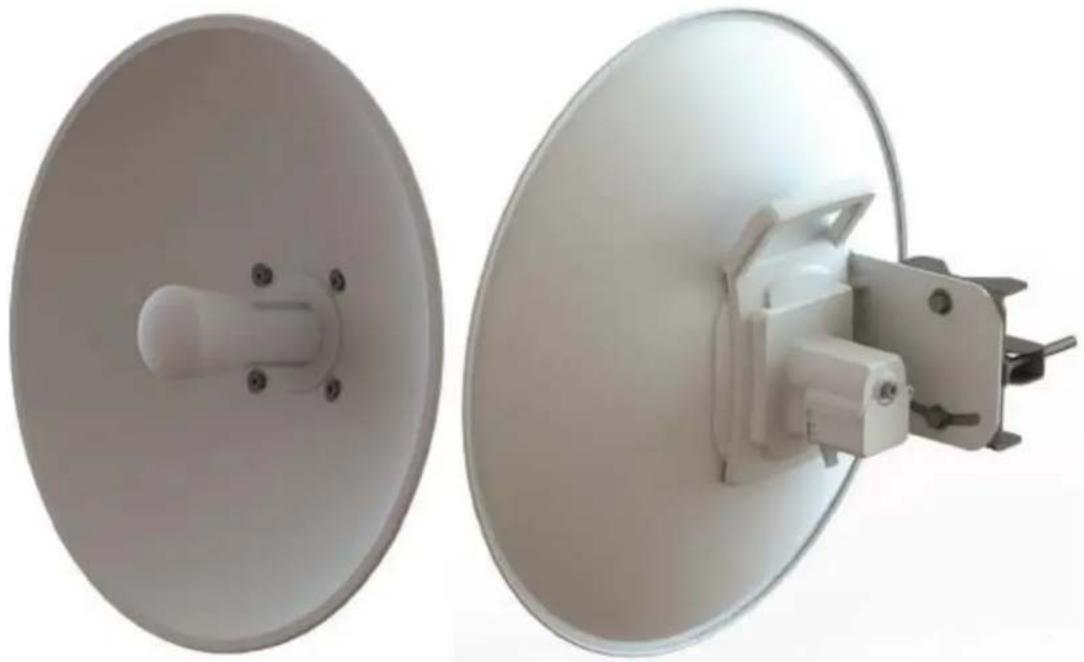
natural_image
Two white satellite dishes with metallic components, one showing a circular top and the other a flat dome (no text or symbols visible)Table 41 PMP/PTP 450b High Gain SM - ODU rear interfaces
| Port name | Connector | Interface | Description |
| PSU/Ethernet Port | RJ45 | PoE input | Power over Ethernet (PoE). |
| 10/100/1000BASE-T Ethernet | Data | ||
| Audio AUX Port | Standard | Alignment tone input | 3.5 mm audio jack for alignment tone |
| 3.5 mm headphones |
Cabling
Ethernet standards and cable lengths
All configurations require a copper Ethernet connection from the ODU (Main PSU port) to the Power supply.
Table 42 PSU drop cable length restrictions
| System configuration | Maximum cable length (m/ft) | ||
| Power supply | PoE powered device on AUX/SYNC port | From power supply to ODU | From ODU to PoE device on AUX/SYNC port |
| Power supply (30W) | None 100 m N/A | ||
| IEEE 802.3at Type 2 | Not supported | ||
| AC Power Injector (60W) | None 100 m N/A | ||
| IEEE 802.3at Type 2 | 100 m in total | ||
| AC+DC enhanced Power Injector | None 100 m N/A | ||
| IEEE 802.3at Type 2 | 100 m in total | ||
| -48 V DC power injector | None | 100 m | N/A |
| IEEE 802.3at Type 2 | 100 m in total | ||
| CMM4 with 56 V supply | None | 100 m | N/A |
| IEEE 802.3at Type 2 | Not supported | ||
| IEEE802.3at compliant supply | None 100 m N/A | ||
| IEEE 802.3at Type 2 | Not supported | ||

Note
The Ethernet connectivity for CMM4 requires the part "Ethernet cable adapter for CMM4 - N000045L001A".
Outdoor copper Cat5e Ethernet cable
Outdoor Cat5e cable is used for all connections that terminate outside the building. For example, connections between the ODU, surge suppressors (if installed), UGPS receivers (if installed) and the power supply injector. This is known as a “drop cable” (Figure 27).
The following practices are essential to the reliability and longevity of cabled connections:
• Use only shielded cables and connectors to resist interference and corrosion.
- For vertical runs, provide cable support and strain relief.
- Include a 2 ft (0.6 m) service loop on each end of the cable to allow for thermal expansion and contraction and to facilitate terminating the cable again when needed.
- Include a drip loop to shed water so that most of the water does not reach the connector at the device.
• Properly crimp all connectors.
• Use dielectric grease on all connectors to resist corrosion.
Order Superior Essex type BBDGe cable from Cambium Networks (Table 43). Other lengths of this cable are available from Superior Essex.
Figure 27 Outdoor drop cable

Table 43 Drop cable part numbers
| Cambium description | Cambium part number |
| 1000 ft Reel Outdoor Copper Clad CAT5E | WB3175 |
| 328 ft (100 m) Reel Outdoor Copper Clad CAT5E | WB3176 |
SFP module kits
SFP module kits allow connection of a PMP 450 Series ODU to a network over an Optical Gigabit Ethernet interface (1000BASE-LX or 1000BASE-SX) full-duplex mode.

Note
PMP 450m supports Fiber SFPs from system release 15.0.3.
Order SFP module kits from Cambium Networks (Table 44).
Table 44 SFP module kit part numbers
| Cambium description | Cambium part number |
| Single Mode Optical SFP Interface per ODU | C000065L008A |
| Multi-mode Optical SFP Interface per ODU | C000065L009A |
| 2.5GBASE-T Copper SFP Interface per ODU | C000065L011A |
To compare the capabilities of the two optical SFP modules, refer to Table 45 and Table 46.
Table 45 Single Mode Optical SFP Interface per ODU (part number C000065L008)
| Core/cladding(microns) | Mode | Bandwidth at 1310 nm (MHz/km) | Maximum length of optical interface | Insertion loss (dB) |
| 62.5/125 | Multi | 500 | 550 m (1800 ft) | 1.67 |
| 50/125 | Multi | 400 | 550 m (1800 ft) | 0.07 |
| 50/125 | Multi | 500 | 550 m (1800 ft) | 1.19 |
| 10/125 | Single | N/A | 5000 m (16400 ft) | 0.16 |
Table 46 Multi-mode Optical SFP Interface per ODU (part number C000065L009)
| Core/cladding(microns) | Mode | Bandwidth at 850 nm (MHz/km) | Maximum length of optical interface | Insertion loss (dB) |
| 62.5/125 | Multi | 160 | 220 m (720 ft) | 2.38 |
| 62.5/125 | Multi | 200 | 275 m (900 ft) | 2.6 |
| 50/125 | Multi | 400 | 500 m (1640 ft) | 3.37 |
| 50/125 | Multi | 500 | 550 m (1800 ft) | 3.56 |
The upgrade kits contain the following components:
• Optical SFP transceiver module (Figure 28)
- Long EMC strain relief cable gland (Figure 29)
• The Ethernet SFP Module Installation Guide
• License key instructions and an entitlement key
Figure 28 Optical SFP transceiver module

Figure 29 Long cable gland

natural_image
Close-up of a metallic cylindrical connector with threaded ends and black caps (no visible text or symbols)Main Ethernet port
The PoE cable pinout diagram for Main port is given below.
Table 47 Main port PoE cable pinout
| RJ45 pin | Interface | Ethernet description | PoE input description |
| 1 | +TxRx0 | +Ve or -Ve | |
| 2 -TxRx0 | |||
| 3 +TxRx1 | +Ve or -Ve | ||
| 6 -TxRx1 | 1000 BaseT Ethernet with PoE In | ||
| 4 +TxRx2 | +Ve or -Ve | ||
| 5 -TxRx2 | |||
| 7 +TxRx3 | +Ve or -Ve | ||
| 8 -TxRx3 |

Note
The PoE input on the Main port accepts any polarity.
Aux port
Table 48 Aux port PoE cable pinout
| RJ45 pin | Interface | Signal description | PoE output description |
| 1 | +TxRx0 | -Ve | |
| 2 -TxRx0 | 100 BaseT Ethernet with PoE Out (see note below) | ||
| 3 +TxRx1 | +Ve | ||
| 6 -TxRx1 | |||
| 4 | GPS power out, Alignment tone out, GPS data out | N/A | |
| 5 GPS data alignment tone | |||
| 7 GPS 0v | |||
| 8 GPS Sync in | |||

Note
If the Aux port will be used, a second Ethernet gland will need to be ordered (Part Number: N000065L033A).
Aux port to alignment tone headset wiring
A standard 32 ohms stereo headset can be connected to the AUX port to use the audio alignment tool. The diagrams of the adapters for RJ45 and RJ12 are provided in Figure 30 and Figure 31 respectively. The recommended values for both resistors are 220 ohm, 0.25W. Different resistor values can be used to optimize the level of the audio signal depending on the headset characteristics and the level of ambient noise.
Figure 30 Alignment Tone Cable

Table 49 Aux port PoE cable pinout
| RJ45 pin(AUX port) | Signal description | Serial component | Jack socket(to jack plug of headset) |
| 4 Alignment tone out | 220 ohms resistor Ring | ||
| 220 ohm resistor Tip | |||
| 7 GPS 0v None Sleeve | |||
Figure 31 RJ12 Alignment Tone Cable

Table 50 RJ12 Aux port PoE cable pinout
| RJ12 pin (AUX port) | Signal description | Jack socket(to jack plug of headset) |
| 5 | Alignment tone out Tip | |
| 6 | Alignment tone out Ring |
Alternatively, a readymade headset adapter can be ordered from Best-Tronics (http://btpa.com/Cambium-Products/) with the following part number:
Table 51 Alignment tone adapter third party product details
| Reference | Product description |
| BT-1277 | Headset alignment cable (RJ-45) for the PMP/PTP 450i Series products |
| BT-0674 | Headset alignment cable (RJ-12) for the PMP/PTP 450 Series products. |
RJ45 connectors and spare glands
RJ45 connectors are required for plugging Cat5e cables into ODUs, LPUs, PSUs and other devices. Order RJ45 connectors and crimp tool from Cambium Networks (Table 52). The ODU is supplied with one environmental sealing gland for the drop cable. This gland is suitable for cable diameters from 5 mm to 9 mm.
Figure 32 Cable gland (part number #N000065L033)

natural_image
Close-up of a metallic connector with threaded metal and black body (no visible text or symbols)Table 52 RJ45 connector and spare gland part numbers
| Cambium description | Cambium part number |
| Tyco/AMP, Mod Plug RJ45, 100 pack | WB3177 |
| Tyco/AMP Crimp Tool WB3211 | |
| RJ-45 Spare Grounding Gland - PG16 size (Qty. 10) | N000065L033 |
Ethernet cable testing
This section describes a procedure for testing the RJ45 Ethernet cables used for Main and AUX port connectivity on 450i and 450m radios.
To test a cable, perform the following instructions:
- Check the resistances of the cable and radio installation using a digital multimeter (DMM).
- Disconnect the drop cable from the power source (EPI or mains adapter) first; keep the radio connected and test the resistances looking towards the radio. Test access can be made via any of the following:
• Directly onto the pins of the RJ45 plug.
• Using a commercially available RJ45 breakout board.
| Measure between | Approximate resistance | Example |
| Wire 1 and wire 2 | 1 ohm + 2 ohms per 10m of cable | For a 20m cable: |
| Wire 3 and wire 6 | Maximum difference between any two readings 0.3 ohms + 0.3 ohms per 10m of cable | Approximate resistance = 1 ohm + 2x 2 ohms = 5 ohms |
| Wire 4 and wire 5 | ||
| Wire 7 and wire 8 | A cable with a single LPU but no radio will read about 3,600 ohms.A cable with a single 1000SS but no radio will read about 7,200 ohms. | Maximum difference between readings = 0.3 ohms + 2x 0.3 ohms = 0.9 ohms |
| Wire 1 and wire 3 | >20 Kohms | |
| Wire 1 and wire 4 | ||
| Wire 1 and wire 7 | ||
| Wire 3 and wire 4 | ||
| Wire 3 and wire 7 | ||
| Wire 4 and wire 7 |

Note
These figures should be indicative only rather than hard limits. The measurement must be done with a low-voltage DMM, not a high-voltage insulation tester.
Lightning protection unit (LPU) and grounding kit
450i and 450m Series LPUs provide transient voltage surge suppression for ODU installations. Each cable requires two LPUs, one near the ODU and the other near the linked device, usually at the building entry point (Table 53).
Table 53 LPU and grounding kit contents
Lightning protection units (LPUs)
LPU grounding point nuts and washers

natural_image
Two metallic automotive electrical enclosures with yellow connectors and a red wire, shown from different angles (no text or symbols visible)ODU to top LPU drop cable (600 mm)
EMC strain relief cable glands

natural_image
Coiled black cable with multiple black connectors, no visible text or symbolsU-bolts, nuts and washers for mounting LPUs
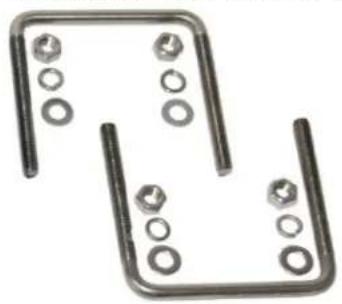
natural_image
Two metallic mechanical components with bolt holes and flanges, no text or symbols visibleODU to top LPU ground cable (M6-M6)

natural_image
Black cable with three metal fittings and a small screw, isolated on white background (no text or symbols)Bottom LPU ground cable (M6-M10)
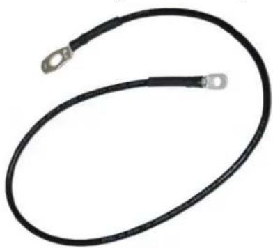
natural_image
Coiled black electrical fuse with terminal connectors (no text or symbols visible)ODU to ground cable (M6-M10
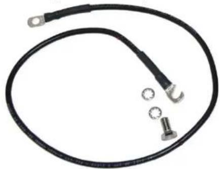
natural_image
Coiled black electrical fuse with two terminal connectors and three small circular components (no text or symbols visible)One LPU and grounding kit (Table 53) is required for the PSU drop cable connection to the ODU. If the ODU is to be connected to an auxiliary device, one additional LPU and grounding kit is required for the Aux drop cable. Order the kits from Cambium Networks (Table 54).
Table 54 LPU and grounding kit part number
| Cambium description | Cambium part number |
| Aux ports LPU and Grounding Kit (One Kit Per End) | C000065L007B |
When using LPUs on the Ethernet Ports of the 3 GHz 450m, a separate PoE power supply must be used at the bottom of the mast to forward bias the diodes in the LPUs. This should be placed in the same position as used in a PoE Ethernet Port. If this is not done, CRC errors will occur on the Ethernet interface.
DC LPU and Grounding Kit
450m 3GHz LPUs provide transient voltage surge suppression for ODU installations. Each cable requires two LPUs, one near the ODU and the other near the linked device, usually at the building entry point.
Table 55 DC LPU and grounding kit contents
| Lightning protection units (LPUs)LPU grounding point nuts and washers | EMC strain relief cable glands |
 |  |
U-bolts, nuts and washers for mounting LPUs

natural_image
Two metallic U-shaped metal components with bolt holes and bolts, no text or symbols visibleODU to top LPU ground cable (M6-M6), bolt and washers

natural_image
Coiled black electrical fuse with terminal fittings and mounting holes (no text or symbols visible)ODU to grounding system ground cable, bottom LPU ground cable (2pcs, M6 and M10 lugs), bolt and washers

natural_image
Two black automotive power plug connectors with terminal fittings and mounting holes (no text or symbols visible)4-pin connector kits (4 kits, one shown)
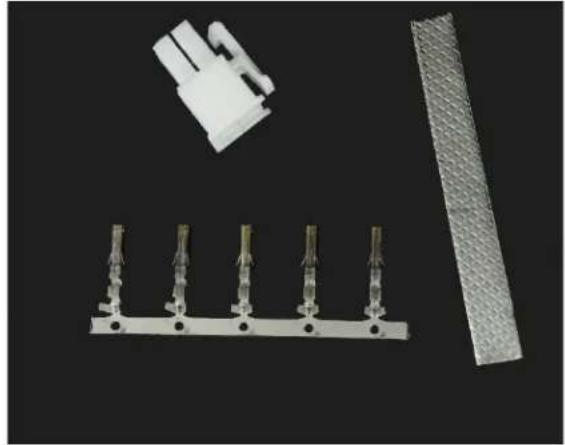
natural_image
Product photo showing a white plastic connector, five metallic connectors, and a textured gray sheet on a black background (no text or symbols visible)One LPU and grounding kit (Table 53) is required for the PSU drop cable connection to the ODU. If the ODU is to be connected to an auxiliary device, one additional LPU and grounding kit is required for the Aux drop cable. Order the kits from Cambium Networks (Table 56)

Note
When installing LPUs, use only EMC cable glands supplied in the ODU and LPU kits (with black caps). Do not use the non-EMC cable glands supplied in other kits (with silver caps), as these may only be used in ODU installations without LPUs.
Table 56 DC LPU and grounding kit part number
| Cambium description | Cambium part number |
DC LPU and Grounding Kit
C000000L114A
Cable grounding kit
Copper drop cable shields must be bonded to the grounding system in order to prevent lightning-strike arcing (resulting in fire risk and damage to equipment).
One grounding kit (Figure 33) is required for each grounding point on the cable. Order cable grounding kits from Cambium Networks (Table 54, Table 56).

Caution
To provide adequate protection, all grounding cables must be a minimum size of 10 mm^-2 csa (8AWG), preferably 16 mm^-2 csa (6AWG), or 25 mm^-2 csa (4AWG).
Figure 33 Cable grounding kit

natural_image
Assorted electrical components including wires, clamps, and a black tape on a plain surface (no text or symbols visible)Table 57 Cable grounding kit part numbers
| Cambium description | Cambium part number |
| Cable Grounding Kits For 1/4" And 3/8" Cable | 01010419001 |
Antennas and antenna cabling
Antenna requirements
Each connectorized ODU requires one external antenna (normally dual-polar).
For connectorized units operating in the USA or Canada 900 MHz, 4.9 GHz, 5.1 GHz, 5.2 GHz, 5.4 GHz or 5.8 GHz bands, choose external antennas which are recommended by Cambium Networks. Do not install any other antennas.
Supported external AP antennas
The recommended AP external antennas are listed in Table 58.
Table 58 List of AP external antennas
| Cambium description | Cambium part number |
| 900 MHz 13 dBi 65 degree Sector Antenna (Dual Slant) | N009045D001A |
| 5 GHz Horizontal and Vertical Polarization Antenna for 90 Degree Sector | 85009324001 |
| 5 GHz Horizontal and Vertical Polarization Antenna for 60 Degree Sector | 85009325001 |

Note
LINKPlanner, Cambium Networks, planning tool, contains an up-to-date, exhaustive list of antennas that can be used with Cambium Products.
Supported external BH/SM antenna
The recommended PTP 450i Series BH or PMP 450/450i Series SM external antenna is listed in Table 59.
Table 59 PTP 450i Series BH or PMP 450/450i Series SM external antenna
| Cambium description | Cambium part number |
| 900 MHz 12 dBi gain directional antenna (Dual Slant) | N009045D003A |
RF cable and connectors
RF cable of generic type LMR-400 is required for connecting the ODU to the antenna. N type male connectors are required for connecting the RF cables to the connectorized ODU. Two connectors are required per ODU. Use weatherproof connectors, preferably ones that are supplied with adhesive lined heat shrink sleeves that are fitted over the interface between the cable and connector. Order CNT-400 RF cable and N type male connectors from Cambium Networks (Table 60).
Table 60 RF cable and connector part numbers
| Cambium description | Cambium part number |
| 50 Ohm Braided Coaxial Cable - 75 meter | 30010194001 |
| 50 Ohm Braided Coaxial Cable - 500 meter | 30010195001 |
| RF Connector, N, Male, Straight for CNT-400 Cable | 09010091001 |
Antenna accessories
Connectorized ODUs require the following additional components:
- Cable grounding kits: Order one cable grounding kit for each grounding point on the antenna cables. Refer to Ethernet cable testing on 2-48.
- Self-amalgamating and PVC tape: Order these items to weatherproof the RF connectors
- Lightning arrestors: When the connectorized ODU is mounted indoors, lightning arrestors (not LPUs) are required for protecting the antenna RF cables at building entry. One arrestor is required per antenna cable. One example of a compatible lightning arrestor is the Polyphaser LSXL-ME or LSXL (not supplied by Cambium Networks).
GPS synchronization
GPS synchronization description
Cambium offers GPS synchronization to limit the network's own self-interference. The Cluster Management CMM provides Global Positioning System (GPS) synchronization to the Access Point (AP) and all associated Subscriber Modules (SM). Network operators have a choice of UGPS and CMM solutions to select the option that works best for the environment.
Universal GPS (UGPS)
The UGPS provides network synchronization for smaller networks where a CMM may not be cost effective. The UGPS provides synchronization for one or two modules so that even remote areas at the edge of the network can operate with synchronization for improved performance. The UGPS works with all Cambium PMP radios. The UGPS has a small footprint and is easy to deploy.
Figure 34 UGPS

natural_image
White rectangular electronic device mounted on a black base with cables, next to a vertical cylindrical component (no visible text or symbols)
Note
PMP 450/450i/450m Series - APs can power up a UGPS via the Aux/Timing port.

Note
PMP 450i/450b/450m Series - If two units are to get sync from the UGPS, then an external power supply is required.
If the GPS position information is required to be visible on the web GUI, then the UGPS power must be enabled on the AP; and it is safe to use both AP power and external power for a single UGPS unit.
CMM5
The CMM5 (Cluster Management Module) is the latest generation of solutions for the distribution of TDD Sync signals and “Power-over-Ethernet (PoE)” in the field. The CMM5 is a modular design with individual 4-port power injectors and an optional controller used for remote management.
Key features of the CMM5 include:
• Support for Gigabit Ethernet (1000BaseT)
- Modular and scalable from 4 ports to 32 ports
- Direct +/- 48VDC input (optional AC/DC power supplies are available from Cambium Networks)
• Uses Cambium Networks UGPS for a synchronization source
• Dual resilient power inputs
- Rack mountable
- Secure remote management when used with the optional CMM5 Controller Module
• Support for PMP 450m (cnMedusa™)
- Future support for integration into (cnMedusa™) for cloud or NOC-based management
It consists of four subsystems, described in the following sections:
• CMM5 Controller Module
• CMM5 Injector (29 volt and 56 volt versions)
• Power supply(s) (240/600 watt)
- UGPS
Cluster Management: Scenario 1
The following is a CMM5 Cluster Management scenario using four PMP 450i Access Points.
Table 61 CMM5 Cluster Management Scenario 1
| Scenario | Equipment Needed | Features |
| Four PMP 450i Access Points | 56 Volt Injector | Gigabit EthernetLocal Management Interface+/- 48VDC InputBroad Device SupportRack Mountable |
| 48 VDC AvailableNo management or resilience required | UGPS - |
Figure 35 Cluster Management: Scenario 1

flowchart
graph TD
    A["1PPS Signal from uGPS"] --> B["to Access Points (Data+Power+SYNC)"]
    B --> C["DC Power"]
    C --> D["+/- 48VDC Power Source"]
    C --> E["to LAN (Data)"]
    E --> F["to Access Points (Data+Power+SYNC)"]
    F --> G["DC Power"]
    G --> H["+/- 48VDC Power Source"]
Cluster Management: Scenario 2
The following is a CMM5 Cluster Management scenario using four PMP 450i Access Points and four PMP 450 Access Points.
Table 62 CMM5 Cluster Management Scenario 2
| Scenario | Equipment Needed | Features |
| Four PMP 450i Access Points | 56 Volt Injector29 Volt Injector1 CMM5 ControllerOne UGPS | Gigabit Ethernet supportLocal Management Interface+/- 48VDC InputBroad Device SupportRack Mountable |
| Four PMP 450 Access Points | ||
| AC only environments | Two UGPS AC-to-48 VDC Power Supplies | Resilient power sources |
| Management required Resilience required | - Secure, Remote | Management (https)Scalable to 32 devices |
Figure 36 Cluster Management: Scenario 2

flowchart
graph TD
    A["to Access Points (Data+Power+SYNC)"] --> B["Daisy-chain (RJ-12)"]
    B --> C["to LAN (Data)"]
    C --> D["to Access Points (Data+Power+SYNC)"]
    D --> E["Controller to 1st CMM5"]
    E --> F["1PPS Signal from uGPS"]
    F --> G["to LAN (Network Mgmt)"]
    G --> H["to LAN (Data)"]
    H --> I["Daisy-chain (RJ-12)"]
    I --> J["to Access Points (Data+Power+SYNC)"]
    J --> K["Controller to 1st CMM5"]
    K --> L["to LAN (Network Mgmt)"]
    L --> M["to LAN (Data)"]
    M --> N["Daisy-chain (RJ-12)"]
    N --> O["to Access Points (Data+Power+SYNC)"]
    O --> P["Controller to 1st CMM5"]
    P --> Q["to LAN (Network Mgmt)"]
    Q --> R["Daisy-chain (RJ-12)"]
    R --> S["to Access Points (Data+Power+SYNC)"]
    S --> T["Controller to 1st CMM5"]
CMM5 Controller Module
The major features of the CMM5 Controller Module are:
• Auto-detect/control up to 8 Power Injectors
• Monitor SYNC/Power/GPS status
- Manage (up/down ports)
• Web (HTTPS) and SNMPv2/v3 management (SNMP on roadmap)
• 1U/half-width rack-mount
Figure 37 Controller Module

CMM5 Injector Module
The CMM5 Injector Module has the following features:
- Stand-alone mode or used with controller for mgmt.
• +/- 48VDC input with green/amber LED's for status
• Injects SYNC pulse from UGPS
• 2U / half-width rack-mount

Note
There are two different versions of the injector module (56V and 29V). You must select the correct injector for the types of radios that you will be powering. In both cases, the injectors use the same input power supplies or can be powered with +/- 48VDC. The output power is different and the type of SYNC signal used is different between the two types of injectors. Systems can have 29V and 56V injectors deployed alongside each other.
Figure 38 Injector Module

CMM5 Injector Compatibility Matrix
The following table provides the Injector compatibility matrix.
Table 63 Injector Compatibility Matrix
| Product | Power/Injector Module | Sync |
| PMP 450m | Yes/56V | Yes |
| PMP/PTP 450i | Yes/56V | Yes |
| PMP 450b | Yes/29V | Yes |
| PMP 450/PTP 450 | Yes/29V | Yes |
| PMP 100/PTP 100 | Yes/29V | Yes |
CMM5 Specifications
The following table provides specifications for the CMM5 Power & Sync Injector (56 Volts).
Table 64 CMM5 Specifications
| CMM5 Power and Sync Injector 56 Volts | |
| Model Number C000000L556A | |
| Data Interface | 4 each RJ45 Gigabit Powered output ports “To Radios”4 each RJ45 Gigabit Data input ports “To Switch Array”1 each GPS timing port (RJ-12)1 each CMM5 USB Serial port for local administration1 each RJ12 Daisy Chain port “IN”1 each RJ12 Daisy Chain port “OUT” |
| Surge Suppression | Lightning Suppression for each “To Radios” RJ45 Port |
| Power | Input Voltage: + or - 48 VDCInput Power Consumption: 400 wattsOutput Voltage: + or - 55 VDCOutput Current: 0 - 1.8A per channelOutput Power: 0 - 90 Watts per channel |
| Cabinet Temperature | -40°C to +55°C (-40°F to +131°F), 90% humidity, condensing |
| Physical | Max Distance from Managed Radios: 328 cable feet (100m)Max Distance to GPS Antenna: 100 cable feet (30.5m) |
| Dimensions 8.85” W x 15.75” D x 1.65” H (225mm x 400mm x 42mm) | |
| Unit Weight 6.6 pounds (3kg) | |
| Power Interface Terminals | 2 Power input ports for 48 VDC Power (Power supplies sold separately) |

Note
DC Power Input requirement is +/- 48VDC and must not exceed 100V surges. If surges above 100 VDC are expected, a suitable in-line DC surge suppressor with 48 VDC nominal voltage is required.
CMM4 (Rack Mount)
The Cluster Management Module (CMM) is the heart of the Cambium system's synchronization capability, which allows network operators to reuse frequencies and add capacity while ensuring consistency in the quality of service to customers.
For operators who prefer indoor CMM mounting, Cambium offers the Rack-Mounted Cluster Management Module 4. The unit is designed to be mounted onto a standard 19-inch telecommunications rack and to allow the Cambium CMM4 to be co-located with other telecommunications equipment.
Figure 39 CMM4 (Rack Mount)
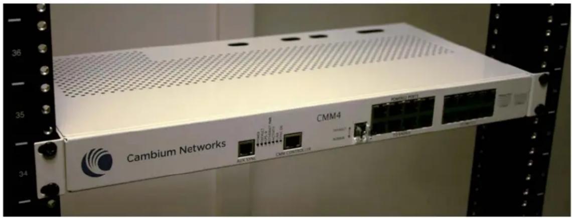
natural_image
Front view of a Cambium Networks networking device with visible ports and connectors (no readable text beyond branding)The CMM4 has two DC power inputs, one 29 V and one 56V. It can be used to power and synchronize both 29 V legacy products such as the PMP 450 Series and 56V products such as the PMP 450i Series simultaneously.
If the 29 V legacy products are connected to the CMM4, a 29 V power supply needs to be connected.
If the 450i Series is connected to the CMM4, a 56 V power supply needs to be connected. The CMM4 supports having two of the 56 V and two of the 29 V supplies for redundancy.

Warning
PMP 450i Series requires different wiring between the CMM4 and device. If a PMP450 Series ODU is replaced by a PMP 450i Series and the existing drop cable needs to be re-used, the Ethernet cable adapter for CMM4 - N000045L001A" must be used between the CMM4 and the existing drop cable.
Figure 40 CMM4 56 V power adapter (dongle)

natural_image
Close-up of a black USB cable with connector port, isolated on white background (no text or symbols visible)CMM4 56 V power adapter cable pinout
Figure 41 CMM4 power adapter cabling diagram
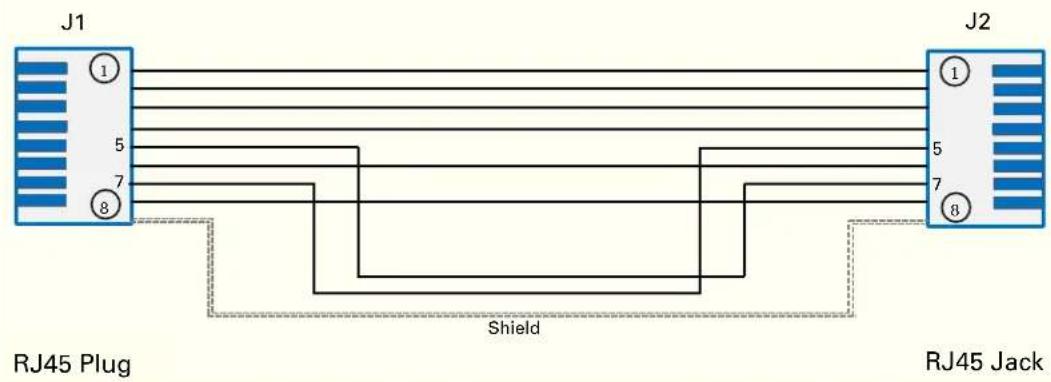
Table 65 CMM4 power adapter cable pinout
| Plug J1 pin | Jack J2 pin |
| 1 1 | |
| 2 2 | |
| 3 3 | |
| 4 4 | |
| 5 7 | |
| 6 6 | |
| 7 5 | |
| 8 8 | |
| Screen Screen | |

Note
Pins 5 and 7 are wired in a cross-over configuration.
CMM4 (Cabinet with switch)
Designed to deliver consistent and reliable wireless broadband service, the PMP/PTP system gracefully scales to support large deployments. The cluster management module is the heart of the system's synchronization capability which allows network operators to re-use frequencies and add capacity while ensuring consistency in the quality of service to customers. As a result, subscribers can experience carrier-grade service even at the outer edge of the network.
Figure 42 CMM4 (Cabinet with switch)

natural_image
Interior view of an open electrical enclosure showing a circuit board, network switch, and wiring (no visible text or symbols)CMM4 (Cabinet without switch)
This CMM includes all the functionality listed above but there is no switch. This provides the network operator the flexibility to use the switch of their choice with the power and synchronization capabilities of the CMM4.
CMM3/CMMmicro
The CMM3 or CMMmicro (Cluster Management Module micro) provides power, GPS timing, and networking connections for an AP cluster. The CMM3 is configurable through a web interface.
The CMM3 contains an 8-port managed switch that supports Power over Ethernet (PoE - this is Cambium PoE, not the standard PoE) on each port and connects any combination of APs, BHMs, BHSs, or Ethernet feed. The Cambium fixed wireless broadband IP networks PoE differs from IEEE Standard 803.3af PoE, and the two should not be intermixed. The CMM3 can auto-negotiate speed to match inputs that are either 100Base-TX or 10Base-T, and either full duplex or half duplex, where the connected device is set to auto-negotiate. Alternatively, these parameters are settable.
A CMM3 requires only one cable, terminating in an RJ-45 connector, for each connected module to distribute
- Ethernet signaling.
- power to as many as 8 co-located modules—APs, BHMs, or BHSs. Through a browser interface to the managed switch, ports can be powered or not.
- sync to APs and BHMs. The CMM3 receives 1-pulse per second timing information from Global Positioning System (GPS) satellites through an antenna (included) and passes the timing pulse embedded in the 24-V power to the connected modules.
GPS status information is available at the CMM3, however
- CMM3 provides time and date information to BHMs and APs if both the CMMmicro is operating on CMMmicro Release 2.1 or later and the AP/BHM is operating on System Release 4.2 or later. See Configuring time settings on Page 7-19.
- CMM3 does not provide time and date information to BHMs and APs if either the CMM3 is operating on a release earlier than CMMmicro Release 2.1 or the AP/BHM is operating on a release earlier than System Release 4.2.
A CMM3/CMMicro is shown in Figure 43 and Figure 44.
Figure 43 CMM3
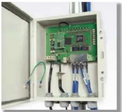
natural_image
Interior view of an open electrical control box with green circuit board and wiring (no visible text or symbols)Figure 44 Pole mounted CMM3

natural_image
Exterior view of a rectangular electronic device with vertical and horizontal lines, no visible text or symbols
Note
A CMM3 cannot be used to power up a 450i or 450m Series ODUs.
Installing a GPS receiver
To install a GPS receiver as the timing reference source, use the following procedures:
• Mounting the GPS receiver on page 2-72
• Cabling the GPS Antenna on page 2-73
• Installing and connecting the GPS LPU on page 2-73

Caution
Prior to power-up of equipment, ensure that all cables are connected to the correct interfaces of the CMM4 unit and the UGPS receiver module. Failure to do so may result in damage to the equipment.
GPS receiver location
Mount the GPS receiver at a location that meets the following requirements:
- It must be possible to protect the installation as described in Grounding and lightning protection on page 3-8.
- It must have an un-interrupted view of at least half of the southern (resp. northern) sky in the northern (resp. southern) hemisphere. For a receiver mounted on a wall there must be no other significant obstructions in the view of the sky.
- It must be mounted at least 1 m (3 ft), preferably 2 m (6 ft), away from other GPS receiving equipment.
- It must not be sited in the field of radiation of co-located radio communications equipment and should be positioned at a distance of at least 3 m (10 ft) away.
Mount the UGPS receiver on the wall of the equipment building if there is a suitable location on the wall that can meet these requirements.

Caution
The GPS receiver is not approved for operation in locations where gas hazards exist, as defined by HAZLOC (USA) and ATEX (Europe).
Mounting the GPS receiver module on the equipment building
If mounting the GPS receiver on the equipment building (Figure 49), select a position on the wall that meets the following requirements:
- It must be below the roof height of the equipment building or below the height of any roof-mounted equipment (such as air conditioning plant).
- It must be below the lightning air terminals.
- It must not project more than 600mm (24 inches) from the wall of the building. If these requirements cannot all be met, then the module must be mounted on a metal tower or mast.
Mounting the GPS receiver module on a metal tower or mast
If mounting the GPS receiver module on a metal tower or mast (Figure 50), select a position that meets the following requirements:
- It must not be mounted any higher than is necessary to receive an adequate signal from four GPS satellites.
- It must be protected by a nearby lightning air terminal that projects farther out from the tower than the GPS receiver module.
Mounting the GPS receiver
Mount the GPS receiver (following manufacturer's instructions) upon either an external wall (Figure 49) or a metal tower or mast (Figure 50).
Figure 45 GPS antenna mounting

natural_image
Two mechanical test devices with metallic components and connectors, one showing a conical sensor mounted on a pole (left) and the other showing a vertical clamp with bolts mounted on a bracket (right).Procedure 1 Mounting the GPS receiver
1 Ensure that the mounting position
- has an unobstructed view of the sky to 20^ above the horizon.
- is not the highest object at the site. (The GPS antenna does not need to be particularly high on a site, which would give it more exposure to lightning. It just needs to have an unobstructed view of the sky.)
• is not further than 100 feet (30.4 meters) of cable from the CMM.
2 Select a pole that has an outside diameter of 1.25 to 1.5 inches (3 to 4 cm) to which the GPS antenna bracket can be mounted.
3 Place the U-bolts (provided) around the pole as shown in Figure 47.
4 Slide the GPS antenna bracket onto the U-bolts.
5 Slide the ring washers (provided) onto the U-bolts.
6 Slide the lock washers (provided) onto the U-bolts.
7 Use the nuts (provided) to securely fasten the bracket to the U-bolts.
Please refer to the PMP Synchronization Solutions User Guide located on the Cambium website (http://www.cambiumnetworks.com/resource/pmp-synchronization-solutions).
Cabling the GPS Antenna
Connect the GPS coax cable to the female N-connector on the GPS antenna. Please refer to the PMP Synchronization Solutions User Guide located on the Cambium website (http://www.cambiumnetworks.com/resource/pmp-synchronization-solutions).
Installing and connecting the GPS LPU
Install and ground the GPS drop cable LPU at the building (or cabinet) entry point, as described in Install the bottom LPU on page 6-25.
Ordering the components
This section describes how to select components for 450m Series, 450i Series and 450 Series Greenfield network or 450m/450i Series network migration. It specifies Cambium part numbers for 450 Platform Family components.
Order PMP 450m Series, PMP/PTP 450i Series and PMP/PTP 450 Series ODUs from Cambium Networks.
PMP 450m
Table 66 PMP 450m Series ODU part numbers
| Cambium description | Cambium part number |
| PMP 450m AP (Access Point) | |
| 3 GHz PMP 450m Integrated Access Point, 90 Degree | C030045A101A |
| 3 GHz PMP 450m Integrated Access Point, 90 Degree | C030045A104A(No Encryption) |
| 3 GHz PMP 450m Integrated Access Point, 90 Degree | C030045A111A(Limited) |
| 3 GHz PMP 450m Integrated Access Point, 90 Degree | C030045A114A(Limited, No Encryption) |
| 5 GHz PMP 450m Integrated Access Point, 90 Degree (ROW) | C050045A101A |
| 5 GHz PMP 450m Integrated Access Point, 90 Degree (FCC) | C050045A102A |
| 5 GHz PMP 450m Integrated Access Point, 90 Degree (EU) | C050045A103A |
| 5 GHz PMP 450m Integrated Access Point, 90 Degree (DES Only) | C050045A104A |
| 5 GHz PMP 450m Integrated Access Point, 90 Degree (IC) | C050045A105A |
PMP 450i
Table 67 PMP 450i Series ODU part numbers
| Cambium description | Cambium part number |
| PMP 450i AP (Access Point) | |
| 900 MHz PMP 450i Connectorized Access Point | C009045A001A |
| 3 GHz PMP 450i Connectorized Access Point C030045A001A | |
| 3 GHz PMP 450i Integrated Access Point, 90 Degree | C030045A002A |
| 3 GHz PMP 450i Connectorized Access Point, DES Only | C030045A003A |
| 3 GHz PMP 450i Integrated Access Point, 90 Degree, DES Only | C030045A004A |
| 5 GHz PMP 450i Connectorized Access Point (RoW) | C050045A001A |
| 5 GHz PMP 450i Connectorized Access Point (FCC) | C050045A002A |
| 5 GHz PMP 450i Connectorized Access Point (EU) C050045A003A | |
| 5 GHz PMP 450i Connectorized Access Point (DES Only) | C050045A004A |
| 5 GHz PMP 450i Connectorized Access Point (IC) | C050045A015A |
| 5 GHz PMP 450i AP, Integrated 90°sector antenna (RoW) | C050045A005A |
| 5 GHz PMP 450i AP, Integrated 90°sector antenna (FCC) | C050045A006A |
| 5 GHz PMP 450i Integrated Access Point, 90 degree (EU) | C050045A007A |
| 5 GHz PMP 450i AP, Integrated 90°sector antenna (DES only) | C050045A008A |
| 5 GHz PMP 450i AP, Integrated 90°sector antenna (IC) | C050045A016A |
| PMP 450i SM (Subscriber Module) | |
| 3 GHz PMP 450i Connectorized Subscriber Module | C030045C001A |
| 3 GHz PMP 450i SM, Integrated High Gain Antenna | C030045C002A |
| 5 GHz PMP 450i Connectorized Subscriber Module | C050045C001A |
| 5 GHz PMP 450i SM, Integrated High Gain Antenna | C050045C002A |

Note
The 450i SM does not have license keys.
Table 68 PMP 450i ATEX/HAZLOC ODU models/part numbers
| ODU model / part number | Description |
| ODU model | |
| 5085CHH | 450i Connectorized ATEX/HAZLOC |
| 5085HH | 450i Integrated 90 Deg Sector ATEX/HAZLOC |
| 5095HH | 450i Integrated High Gain Directional ATEX/HAZLOC |
| Part Number | |
| C050045A009A | 5 GHz PMP 450i Conn Access Point (ROW), ATEX/HAZLOC |
| C050045A010A | 5 GHz PMP 450i Conn Access Point (FCC), ATEX/HAZLOC |
| C050045A011A | 5 GHz PMP 450i Conn Access Point (EU), ATEX/HAZLOC |
| C050045A012A | 5 GHz PMP 450i Integrated Access Point, 90 degree (ROW), ATEX/HAZLOC |
| C050045A013A | 5 GHz PMP 450i Integrated Access Point, 90 degree (FCC), ATEX/HAZLOC |
| C050045A014A | 5 GHz PMP 450i Integrated Access Point, 90 degree (EU), ATEX/HAZLOC |
| C050045A017A | 5 GHz PMP 450i Conn Access Point (IC), ATEX/HAZLOC |
| C050045A018A | 5 GHz PMP 450i Integrated Access Point, 90 degree (IC), ATEX/HAZLOC |
| C050045A019A | 5 GHz PMP 450i Conn Access Point (DES Only), ATEX/HAZLOC |
| C050045A020A | 5 GHz PMP 450i Integrated Access Point, 90 degree (DES Only), ATEX/HAZLOC |
| C050045C003A | 5 GHz PMP 450i Conn Subscriber Module, ATEX/HAZLOC |
| C050045C004A | 5 GHz PMP 450i Integrated High Gain Antenna, ATEX/HAZLOC |
PTP 450i
Table 69 PTP 450i Series ODU part numbers
| Cambium description | Cambium part number |
| 3 GHz PTP 450i END, Connectorized C030045B001A | |
| 3 GHz PTP 450i END, Integrated High Gain Antenna | C030045B002A |
| 3 GHz PTP 450i END, Connectorized (DES only) | C030045B003A |
| 3 GHz PTP 450i END, Integrated Access Point, 90 degree (DES only) | C035045B004A |
| 5 GHz PTP 450i END, Connectorized (RoW) | C050045B001A |
| 5 GHz PTP 450i END, Connectorized (FCC) | C050045B003A |
| 5 GHz PTP 450i END, Connectorized (EU) | C050045B005A |
| 5 GHz PTP 450i END, Connectorized (DES only) | C050045B007A |
| 5 GHz PTP 450i END, Connectorized (IC) | C050045B015A |
| 5 GHz PTP 450i END, Integrated High Gain Antenna (RoW) | C050045B002A |
| 5 GHz PTP 450i END, Integrated High Gain Antenna (FCC) | C050045B004A |
| 5 GHz PTP 450i END, Integrated High Gain Antenna (EU) | C050045B006A |
| 5 GHz PTP 450i END, Integrated High Gain Antenna (DES only) | C050045B008A |
| 5 GHz PTP 450i END, Integrated High Gain Antenna (IC) | C050045B016A |
| Ethernet cable adapter for CMM4 N000045L001A | |
Table 70 PTP 450i ATEX/HAZLOC ODU models/part numbers
| ODU model / part number | Description |
| ODU model | |
| 5085CHH | 450i Connectorized ATEX/HAZLOC |
| 5085HH | 450i Integrated 90 Deg Sector ATEX/HAZLOC |
| 5095HH | 450i Integrated High Gain Directional ATEX/HAZLOC |
| C050045B009A | 5 GHz PTP 450i END, Connectorized (ROW), ATEX/HAZLOC |
| C050045B010A | 5 GHz PTP 450i END, Integrated High Gain Antenna (ROW), ATEX/HAZLOC |
| C050045B011A | 5 GHz PTP 450i END, Connectorized (FCC), ATEX/HAZLOC |
| C050045B012A | 5 GHz PTP 450i END, Integrated High Gain Antenna (FCC), ATEX/HAZLOC |
| C050045B013A | 5 GHz PTP 450i END, Connectorized (EU), ATEX/HAZLOC |
| C050045B014A | 5 GHz PTP 450i END, Integrated High Gain Antenna (EU), ATEX/HAZLOC |
| C050045B017A | 5 GHz PTP 450i END, Connectorized (IC), ATEX/HAZLOC |
| C050045B018A | 5 GHz PTP 450i END, Integrated High Gain Antenna (IC), ATEX/HAZLOC |
| C050045B019A | 5 GHz PTP 450i END, Connectorized (DES Only), ATEX/HAZLOC |
| C050045B020A | 5 GHz PTP 450i END, Integrated High Gain Antenna (DES Only), ATEX/HAZLOC |
PMP 450b
Table 71 PMP 450b Series ODU part numbers
| Cambium description | Cambium part number |
| PMP 450b SM (Subscriber Module) | |
| 5 GHz 450b Mid-Gain WB SM | C050045C011A |
| 5 GHz 450b High Gain WB SM | C050045C012A |
PTP 450b
Table 72 PTP 450b Series ODU part numbers
| Cambium description | Cambium part number |
| PTP 450b SM (Subscriber Module) | |
| 5 GHz 450b - Mid-Gain - ROW | C050045B031A |
| 5 GHz 450b - Mid-Gain - FCC | C050045B032A |
| 5 GHz 450b - Mid-Gain - ISED | C050045B033A |
| 5 GHz 450b - Mid-Gain - EU | C050045B034A |
| 5 GHz 450b - Mid-Gain - No Encryption | C050045B035A |
| 5 GHz 450b - High Gain - ROW | C050045B021A |
| 5 GHz 450b - High Gain - FCC | C050045B022A |
| 5 GHz 450b - High Gain - ISED | C050045B023A |
| 5 GHz 450b - High Gain - EU | C050045B024A |
| 5 GHz 450b - High Gain - No Encryption | C050045B025A |
| 5 GHz 450b, 50 Mbps - High Gain - ROW | C050045B051A |
| 5 GHz 450b - High Gain - Eolo | C050045B029A |
PMP 450
Table 73 PMP 450 Series ODU part numbers
| Cambium description | Cambium part number |
| PMP 450 AP (Access Point) | |
| 2.4 GHz PMP 450 Connectorized Access Point C024045A001A | |
| 2.4 GHz PMP 450 Connectorized Access Point (DES) | C024045A003A |
| 3.5 GHz PMP 450 Connectorized Access Point C035045A001A | |
| 3.5 GHz PMP 450 Connectorized Access Point (DES) | C035045A003A |
| 3.6 GHz PMP 450 Connectorized Access Point C036045A001A | |
| 3.6 GHz PMP 450 Connectorized Access Point (DES) | C036045A003A |
| 5 GHz PMP 450 Connectorized Access Point C054045A001A | |
| 5 GHz PMP 450 Connectorized Access Point (US only) | C054045A002A |
| 5 GHz PMP 450 Connectorized Access Point (DES) | C054045A003A |
| PMP 450 AP Lite | |
| 2.4 GHz PMP 450 Connectorized Access Point - Lite | C024045A011A |
| 3.3-3.6 GHz PMP 450 Connectorized Access Point - Lite | C035045A011A |
| 3.55-3.8 GHz PMP 450 Connectorized Access Point - Lite | C036045A011A |
| 5 GHz PMP 450 Connectorized Access Point - Lite | C054045A011A |
| 5 GHz PMP 450 Connectorized Access Point (FCC) - Lite | C054045A012A |
| PMP 450 SM (Subscriber Module) | |
| 900 MHz PMP 450 Connectorized Subscriber Module | C009045C001A |
| 2.4 GHz PMP 450 Subscriber Module, 4 Mbps | C024045C001A |
| 2.4 GHz PMP 450 Subscriber Module, 10 Mbps | C024045C002A |
| 2.4 GHz PMP 450 Subscriber Module, 20 Mbps | C024045C003A |
| 2.4 GHz PMP 450 Subscriber Module, Uncapped | C024045C004A |
| 2.4 GHz PMP 450 Connectorized Subscriber Module, 4 Mbps | C024045C005A |
| 2.4 GHz PMP 450 Connectorized Subscriber Module, 10 Mbps | C024045C006A |
| 2.4 GHz PMP 450 Connectorized Subscriber Module, 20 Mbps | C024045C007A |
| 2.4 GHz PMP 450 Connectorized Subscriber Module, Uncapped | C024045C008A |
| 3.5 GHz PMP 450 High Gain Directional Integrated Subscriber | C035045C014A |
| 3.5 GHz PMP 450 Subscriber Module, 4 Mbps | C035045C001A |
| 3.5 GHz PMP 450 Subscriber Module, 10 Mbps C035045C002A | |
| 3.5 GHz PMP 450 Subscriber Module, 20 Mbps C035045C003A | |
| 3.5 GHz PMP 450 Subscriber Module, Uncapped C035045C004A | |
| 3.5 GHz PMP 450 Connectorized Subscriber Module, 4 Mbps | C035045C005A |
| 3.5 GHz PMP 450 Connectorized Subscriber Module, 10 Mbps | C035045C006A |
| 3.5 GHz PMP 450 Connectorized Subscriber Module, 20 Mbps | C035045C007A |
| 3.5 GHz PMP 450 Connectorized Subscriber Module, Uncapped | C035045C008A |
| 3.6 GHz PMP 450 High Gain Directional Integrated Subscriber | C036045C014A |
| 3.6 GHz PMP 450 Subscriber Module, 4 Mbps C036045C001A | |
| 3.6 GHz PMP 450 Subscriber Module, 10 Mbps C036045C002A | |
| 3.6 GHz PMP 450 Subscriber Module, 20 Mbps | C036045C003A |
| 3.6 GHz PMP 450 Subscriber Module, Uncapped C036045C004A | |
| 3.6 GHz PMP 450 Connectorized Subscriber Module, 4 Mbps | C036045C005A |
| 3.6 GHz PMP 450 Connectorized Subscriber Module, 10 Mbps | C036045C006A |
| 3.6 GHz PMP 450 Connectorized Subscriber Module, 20 Mbps | C036045C007A |
| 3.6 GHz PMP 450 Connectorized Subscriber Module, Uncapped | C036045C008A |
| 5 GHz PMP 450 Connectorized Subscriber Module, 4 Mbps | C054045C005A |
| 5 GHz PMP 450 Connectorized Subscriber Module, 10 Mbps | C054045C006A |
| 5 GHz PMP 450 Connectorized Subscriber Module, 20 Mbps | C054045C007A |
| 5 GHz PMP 450 Connectorized Subscriber Module, Uncapped | C054045C008A |
| 5 GHz PMP 450 Integrated Subscriber Module, 4 Mbps | C054045C001B |
| 5 GHz PMP 450 Integrated Subscriber Module, 10 Mbps | C054045C002B |
| 5 GHz PMP 450 Integrated Subscriber Module, 20 Mbps | C054045C003B |
| 5 GHz PMP 450 Integrated Subscriber Module, Uncapped | C054045C004B |
| 5 GHz PMP 450 Connectorized Subscriber Module, 4 Mbps | C054045C005B |
| 5 GHz PMP 450 Connectorized Subscriber Module, 10 Mbps | C054045C006B |
| 5 GHz PMP 450 Connectorized Subscriber Module, 20 Mbps | C054045C007B |
| 5 GHz PMP 450 Connectorized Subscriber Module, Uncapped | C054045C008B |
| 5 GHz PMP 450d Subscriber Module, 20 Mbps - 4-pack | C054045H013B |
| 5 GHz PMP 450d Subscriber Module, Uncapped - 4-pack | C054045H014B |
PTP 450
Table 74 PTP 450 Series ODU part numbers
| Cambium description | Cambium part number |
| PTP 450 900 MHz END - Connectorized | C009045B001A |
| PTP 450 3.5 GHz END - Integrated | C035045B001A |
| PTP 450 3.5 GHz END - Connectorized | C035045B002A |
| PTP 450 3.5 GHz END - Integrated - DES Only | C035045B003A |
| PTP 450 3.5 GHz END - Connectorized - DES Only | C035045B004A |
| PTP 450 3.65 GHz END - Integrated | C036045B001A |
| PTP 450 3.65 GHz END - Connectorized | C036045B002A |
| PTP 450 3.65 GHz END - Integrated - DES Only | C036045B003A |
| PTP 450 3.65 GHz END - Connectorized - DES Only | C036045B004A |
| PTP 450 5 GHz END - Integrated (ROW) | C054045B001A |
| PTP 450 5 GHz END - Connectorized (ROW) | C054045B002A |
| PTP 450 5 GHz END - Integrated (ROW) - DES Only | C054045B003A |
| PTP 450 5 GHz END - Connectorized (ROW) - DES Only | C054045B004A |
| PTP 450 5 GHz END - Integrated (FCC) | C054045B005A |
| PTP 450 5 GHz END - Connectorized (FCC) | C054045B006A |
PMP/PTP 450/450i Series Accessories
Table 75 PMP/PTP 450/450i Series Accessories
| Cambium description | Cambium part number |
| PMP 450 AP Antenna Options | |
| 900 MHz 65 degree Sector Antenna (Dual Slant) | N009045D001A |
| 900 MHz 12 dBi gain directional antenna (Dual Slant) | N009045D003A |
| 2.4 GHz Dual Slant Antenna for 60 Degree Sector | C024045D601A |
| 3.5 GHz and 3.6 GHz Dual Slant Antenna for 90 Degree Sector | C030045D901A |
| 5 GHz Antenna for 60 Degree Sector | 85009325001 |
| 5 GHz Antenna for 90 Degree Sector | 85009324001 |
| N-type to N-type cable (16 inch length) | 30009406002 |
| Power supplies | |
| Power supply, 60 W, 56 V with Gbps support | N000065L001B |
| AC+DC Enhanced Power Injector | C000065L002C |
| Line Cord, Fig 8 - US | N000065L003A |
| Line Cord, Fig 8 - UK | N000065L004A |
| Line Cord, Fig 8 - EU | N000065L005A |
| Power over Ethernet midspan, 60 W, -48 VDC Input | N000000L036A |
| Power Supply, 30 W, 56 V - Gbps support | N000000L034A |
| Gigabit Enet Capable Power Supply - 30VDC, 15W | N000900L001A |
| Cable, UL Power Supply Cord Set, US | N000900L007A |
| Cable, UL Power Supply Cord Set, EU | N000900L008A |
| Cable, UL Power Supply Cord Set, UK | N000900L009A |
| AP Optional Equipment | |
| CMM MICRO (Outdoor Enclosure) (450 only) | 1070CKHH |
| CMM5 Controller C000000L500A | |
| CMM5 Power and Sync Injector 56V | C000000L556A |
| UGPS 1096H | |
| CMM5 Power Supply, AC, 56V 240W | N000000L054B |
| CMM5 Power Supply AC, 48V, 640W | N000000L101A |
| CMM5 Spare Controller Cable - 1m | N000000L102A |
| CMM5 to UGPS Shielded Cable (20 meter) | N000000L103A |
| CMM5 Spare DC Power Connector (10 pack) | N000000L104A |
| CMM4 W/RUGGEDIZED Switch and GPS | 1090CKHH |
| CMM4 NO Switch | 1091HH |
| CMM4 Rack Mount Assembly | 1092HH |
| Ethernet cable adapter for CMM4 | N000045L001A |
| Universal GPS Module | 1096H |
| RJ-45 Gland Spare - PG16 style (QTY 10) | N000065L033A |
| Blanking Plug Pack (Qty 10) | N000065L036A |
| SM Optional Equipment | |
| Power Supply, 30 W, 56 V - Gbps support | N000000L034A |
| Gigabit Enet Capable Power Supply - 30 VDC, 15 W | N000900L001A |
| Cable, UL Power Supply Cord Set, US | N000900L007A |
| Cable, UL Power Supply Cord Set, EU | N000900L008A |
| Cable, UL Power Supply Cord Set, UK | N000900L009A |
| 53CM Offset, Reflector Dish Kit, 4PK | HK2022A |
| Alignment Tool Headset | ACATHS-01A |
| Accessories | |
| Surge Suppressor (30 VDC) 600SSH | |
| Gigabit Surge Suppressor (56 VDC) | C000000L033A |
| LPU and Grounding Kit (1 kit per ODU) | C000065L007B |
| Single Mode Optical SFP Interface per ODU | C000065L008A |
| Multimode Kit C000065L009A | |
| 50 Ohm Braided Coaxial Cable - 75 meter | 30010194001 |
| 50 Ohm Braided Coaxial Cable - 500 meter | 30010195001 |
| RF Connector, N, Male, Straight for CNT-400 Cable | 09010091001 |
| Tyco/AMP, Mod Plug RJ45, 100 pack | WB3177 |
| Tyco/AMP Crimp Tool | WB3211 |
| RJ-45 Spare Grounding Gland - PG16 size (Qty. 10) | N000065L033 |
| DC LPU and Grounding Kit | C000000L114A |
| Mounting brackets | |
| Tilt Bracket Assembly | N000045L002A |
| Mounting Bracket (Integrated) | N000065L031A |
| Mounting Bracket (Connectorized) | N000065L032A |
| Upgrade Keys | |
| PMP 450 4 To 10 Mbps Upgrade Key | C000045K002A |
| PMP 450 4 To 20 Mbps Upgrade Key | C000045K003A |
| PMP 450 4 To Uncapped Upgrade Key | C000045K004A |
| PMP 450 10 To 20 Mbps Upgrade Key | C000045K005A |
| PMP 450 10 To Uncapped MBPS Upgrade Key | C000045K006A |
| PMP 450 20 To Uncapped MBPS Upgrade Key | C000045K007A |
| PMP 450 Lite AP to Full AP Upgrade Key C000045K008A | |
| Extended Warranty | |
| PMP 450 Platform AP Extended Warranty, 1 Additional Year | SG00TS4009A |
| PMP 450 Platform AP Extended Warranty, 2 Additional Years | SG00TS4017A |
| PMP 450 Platform AP Extended Warranty, 4 Additional Years | SG00TS4025A |
| PMP 450 Platform SM Extended Warranty, 1 Additional Year | SG00TS4010A |
| PMP 450 Platform SM Extended Warranty, 2 Additional Years | SG00TS4018A |
| PMP 450 Platform SM Extended Warranty, 4 Additional Years | SG00TS4026A |
Chapter 3: System planning
This chapter provides information to help the user to plan a PMP/PTP 450 Platform link. The following topics are described in this chapter:
- Typical deployment on page 3-2 contains diagrams illustrating typical PMP/PTP 450 Platform site deployments.
- Site planning on page 3-7 describes factors to be considered when planning the proposed link end sites, including grounding, lightning protection and equipment location.
- Radio Frequency planning on page 3-18 describes how to plan PMP/PTP 450 Platform links to conform to the regulatory restrictions that apply in the country of operation.
- Link planning on page 3-28 describes factors to be taken into account when planning links, such as range, path loss and throughput.
- Planning for connectorized units on page 3-31 describes factors to be taken into account when planning to use connectorized ODUs with external antennas in PMP/PTP 450 Platform links.
- Data network planning on page 3-33 describes factors to be considered when planning PMP/PTP 450 Platform data networks.
- Network management planning on page 3-41 describes how to plan for PMP/PTP 450 Platform links to be managed remotely using SNMP.
- Security planning on page 3-42 describes how to plan for PMP/PTP 450 Platform links to operate in secure mode.
- Remote AP Deployment on page 3-52 describes how to deploy Remote AP.
Typical deployment
This section contains diagrams illustrating typical PMP/PTP 450 Platform site deployments.
ODU with PoE interface to PSU
In the basic configuration, there is only one Ethernet interface, a copper cable for Power over Ethernet (PoE) from the PSU to the ODU (PSU port), as shown in the following diagrams: mast or tower installation (Figure 46), wall installation (Figure 47) and roof installation (Figure 48).
Figure 46 Mast or tower installation

flowchart
graph TD
    A["Power over Ethernet CAT5e cable (gel-filled, shielded with copper-plated steel)"] --> B["ODU"]
    C["Network k CAT5e cable"] --> D["ODU"]
    E["ODU"] --> F["First point of contact between drop cable and tower"]
    G["Site grounding system"] --> H["Intermediate ground cable(s) as required"]
    I["Building entry"] --> J["Tower ground bar"]
    K["Ground ring"] --> L["Equipment building or cabinet"]
    M["Bottom LPU"] --> N["PSU"]
    O["AC supply"] --> P["Network equipment"]
    Q["Power"] --> R["Power over Ethernet CAT5e cable"]
    S["ODU"] --> T["ODU"]
    U["Intermediate ground cable(s)"] --> V["Intermediate ground cable(s)"]
    W["Building"] --> X["Tower ground bar"]
Figure 47 Wall installation

flowchart
graph TD
    A["Power over Ethernet CAT5e cable (gel-filled, shielded with copper-plated steel)"] --> B["ODU"]
    C["Network k Cat5e cable"] --> B
    D["ODU ground cables"] --> B
    E["Site grounding system"] --> B
    B --> F["First point of contact between drop cable and w all"]
    G["Building entry"] --> H["Bottom LPU"]
    I["PSU"] --> J["AC supply"]
    K["Network equipment"] --> L["Ground ring"]
    M["Ground ring"] --> N["Ground ring"]
Figure 48 Roof installation

flowchart
graph TD
    A["Power over Ethernet CAT5e cable (gel-filled, shielded with copper-plated steel)"] --> B["Networ k CAT5e cable"]
    B --> C["ODU ground cables"]
    C --> D["Site grounding system"]
    E["Air terminals (finials)"] --> F["Tower grounding conductor"]
    F --> G["Building entry point"]
    G --> H["Drop cable inside building"]
    I["Equipment room"] --> J["Bottom LPU"]
    J --> K["PSU"]
    K --> L["Network equipment"]
    L --> M["AC supply"]
    M --> N["Building ground ring"]
    O["Equipment room entry point"] --> P["AC service"]
Figure 49 GPS receiver wall installation
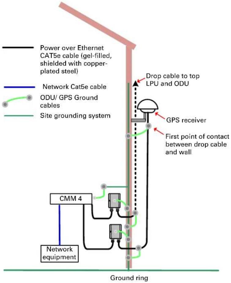
flowchart
graph TD
    A["Power over Ethernet CAT5e cable (gel-filled, shielded with copper-plated steel)"] --> B["Network Cat5e cable"]
    B --> C["ODU/ GPS Ground cables"]
    C --> D["Site grounding system"]
    D --> E["GPS receiver"]
    E --> F["First point of contact between drop cable and wall"]
    F --> G["Drop cable to top LPU and ODU"]
    H["CMM 4"] --> I["Network equipment"]
    I --> J["Ground ring"]
Figure 50 GPS receiver tower or mast installation
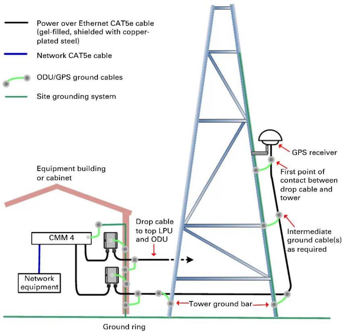
flowchart
graph TD
    A["Equipment building or cabinet"] --> B["CMM 4"]
    B --> C["Network equipment"]
    C --> D["Network CAT5e cable"]
    D --> E["Power over Ethernet CAT5e cable (gel-filled, shielded with copper-plated steel)"]
    E --> F["ODU/GPS ground cables"]
    F --> G["GPS receiver"]
    G --> H["First point of contact between drop cable and tower"]
    H --> I["Intermediate ground cable(s) as required"]
    I --> J["Tower ground bar"]
    J --> K["Ground ring"]
    style A fill:#f9f,stroke:#333
    style B fill:#ccf,stroke:#333
    style C fill:#cfc,stroke:#333
    style D fill:#fcc,stroke:#333
    style E fill:#cff,stroke:#333
    style F fill:#ffc,stroke:#333
    style G fill:#fcf,stroke:#333
    style H fill:#cff,stroke:#333
    style I fill:#cfc,stroke:#333
    style J fill:#cfc,stroke:#333
    style K fill:#fcc,stroke:#333
Site planning
This section describes factors to be considered when choosing sites for PMP or PTP radios, power supplies, CMM4 (if applicable) and UGPS (if applicable).
Site selection for PMP/PTP radios
When selecting a site for the ODU, consider the following factors:
- Height and location to ensure that people are kept away from the antenna; see Calculated distances and power compliance margins on page 4-26.
• Height and location to achieve the best radio path. - Indoor location where the power supply LED indicators will be visible, so the drop cable length will not exceed the maximum recommended length; see Power supply site selection on page 3-8.
- Ability to meet the requirements specified in Grounding and lightning protection on page 3-8.
• Aesthetics and planning permission issues. - Cable lengths; see Ethernet standards and cable lengths on page 2-40.
• The effect of strong winds on the installation; see ODU wind loading on page 3-11.
Power supply site selection
When selecting a site for the ODU power supply, consider the following factors:
- Indoor location with no possibility of condensation, flooding or high humidity.
• Availability of a mains electricity supply. - Located in an environment where it is not likely to exceed its operational temperature rating, allowing for natural convection cooling.
- Accessibility for viewing status indicator LED and connecting Ethernet cables.
- Cable lengths; see Ethernet standards and cable lengths on page 2-40.
Maximum cable lengths
When installing PMP/PTP 450i Series ODU, the maximum permitted length of the shielded copper Ethernet interface cable is 330 feet (100m) from AP/BHM/SM/BHS to their associated power supplies or CMM4.
When installing PMP 450m Series ODU, the maximum permitted length of the shielded copper Ethernet interface cable is 330 feet (100m) from ODU to the network interface equipment.
The 3GHz PMP 450M ODU can use a 1.0 mm ^2 , 984.25 feet (300m) power cable.
Grounding and lightning protection

Warning
Electro-magnetic discharge (lightning) damage is not covered under warranty. The recommendations in this guide, when followed correctly, give the user the best protection from the harmful effects of EMD. However, 100% protection is neither implied nor possible.
Structures, equipment and people must be protected against power surges (typically caused by lightning) by conducting the surge current to ground via a separate preferential solid path. The actual degree of protection required depends on local conditions and applicable local regulations. To adequately protect a PMP/PTP 450 Platform installation, both ground bonding and transient voltage surge suppression are required.
Full details of lightning protection methods and requirements can be found in the international standards IEC 61024-1 and IEC 61312-1, the U.S. National Electric Code ANSI/NFPA No. 70-1984 or section 54 of the Canadian Electric Code.

Warning
International and national standards take precedence over the requirements in this guide.
Lightning protection zones
Use the rolling sphere method (Figure 51) to determine where it is safe to mount equipment. An imaginary sphere, typically 50 meters in radius, is rolled over the structure. Where the sphere rests against the ground and a strike termination device (such as a finial or ground bar), all the space under the sphere is considered to be in the zone of protection (Zone B). Similarly, where the sphere rests on two finials, the space under the sphere is considered to be in the zone of protection.
Figure 51 Rolling sphere method to determine the lightning protection zones

Zone A: In this zone a direct lightning strike is possible. Do not mount equipment in this zone. Zone B: In this zone, direct EMD (lightning) effects are still possible, but mounting in this zone significantly reduces the possibility of a direct strike. Mount equipment in this zone.

Warning
Never mount equipment in Zone A. Mounting in Zone A may put equipment, structures and life at risk.
Site grounding system
Confirm that the site has a correctly installed grounding system on a common ground ring with access points for grounding the 450 Platform Family ODU.
If the outdoor equipment is to be installed on the roof of a high building (Figure 48), confirm that the following additional requirements are met:
- A grounding conductor is installed around the roof perimeter to form the main roof perimeter lightning protection ring.
- Air terminals are installed along the length of the main roof perimeter lightning protection ring, typically every 6.1m (20ft).
- The main roof perimeter lightning protection ring contains at least two down conductors connected to the grounding electrode system. The down conductors should be physically separated from one another, as far as practical.
ODU and external antenna location
Find a location for the ODU (and external antenna for connectorized units) that meets the following requirements:
• The equipment is high enough to achieve the best radio path.
- People can be kept a safe distance away from the equipment when it is radiating. The safe separation distances are defined in Calculated distances and power compliance margins on page 4-26.
- The equipment is lower than the top of the supporting structure (tower, mast or building) or its lightning air terminal.
- If the ODU is connectorized, select a mounting position that gives it maximum protection from the elements, but still allows easy access for connecting and weatherproofing the cables. To minimize cable losses, select a position where the antenna cable lengths can be minimized. If diverse or two external antennas are being deployed, it is not necessary to mount the ODU at the midpoint of the antennas.
ODU ambient temperature limits
Select a location where the ODU can operate within safe ambient temperature limits. The following points need to be considered while selecting a location for the ODU:
- The ODU must be mounted in a Restricted Access Location (as defined in EN 60950-1) if the operating ambient temperature may exceed 40°C, including solar radiation.
- If the ambient temperature never exceeds 40^ C, the temperature of the external metal case parts of the ODU will not exceed the touch temperature limit of 70^ C.
- If the ambient temperature never exceeds 60^ C, the temperature of the external metal case parts of the ODU will not exceed the touch temperature limit of 90^ C.

Note
A restricted access location is defined (in EN 60950-1) as one where access may only be gained by use of a tool or lock and key, or other means of security, and access is controlled by the authority responsible for the location. Access must only be gained by persons who have been instructed about the reasons for the restrictions applied to the location and about any precautions that must be taken. Examples of permissible restricted access locations are a lockable equipment room or a lockable cabinet.
ODU wind loading
Ensure that the ODU and the structure on which it is mounted are capable of withstanding the prevalent wind speeds at a proposed 450 Platform site. Wind speed statistics are available from national meteorological offices.
The ODU and its mounting bracket are capable of withstanding wind speeds of:
- Up to 200 mph (322 kph) for PMP 450m Series - AP 5 GHz
- Up to 124 mph (200 kph) for PMP 450m Series - AP 3 GHz
- Up to 124 mph (Integrated) for PMP/PTP 450i – all models 3 GHz and 5 GHz
- Up to 200 mph (Connectorized) for PMP/PTP 450i - all models 3 GHz and 5 GHz
• Up to 200 mph (322 kph) for PMP/PTP 450 - all models - Up to 200 mph (322 kph) for PMP 450 - Ruggedized
- Up to 200 mph (322 kph) for PMP 450i - all models 900 MHz
• Up to 118 mph (191 kph) for PMP 450b Mid-Gain
• Up to 90 mph (145 kph) for PMP 450b High Gain
• Up to 90 mph (145 kph) for PMP 450d
• Up to 100 mph (161 kph) for 900 MHz antennas
Wind blowing on the ODU will subject the mounting structure to significant lateral force. The magnitude of the force depends on both wind strength and surface area of the ODU. Wind loading is estimated using the following formulae:
• Force (in kilograms) = 0.1045aV ^2
where:
o "a" is the surface area in square meters, and
- "V" is the wind speed in meters per second.
• Force (in pounds) = 0.0042Av ^2
where:
- "A" is the surface area in square feet, and
o "v" is the wind speed in miles per hour.
Applying these formulae to the 450 platform at different wind speeds, the resulting wind loadings are shown in below tables.
Table 76 PMP 450m Series wind loading (Newton)
| Type of ODU | Max surface area (square meters) | Wind speed (kilometer per hour) | ||||
| 160 | 170 | 180 | 190 | 200 | ||
| Integrated 90 ^ sector antenna | 0.331 | 671 | 757 | 849 | 946 | 1048 |
Table 77 PMP/PTP 450i Series wind loading (Newton)
| Type of ODU | Max surface area (square meters) | Wind speed (kilometer per hour) | ||||
| 160 | 170 | 180 | 190 | 200 | ||
| Connectorized | 0.035 | 94 | 106 | 119 | 132 | 146 |
| Directional Yagi antenna - 900 MHz | 0.025 | 67 | 76 | 85 | 94 | 105 |
| External 65° sector antenna - 900 MHz | 0.253 | 677 | 764 | 857 | 954 | 1058 |
| Directional antenna - 3.x GHz | 0.1 | 142 | 160 | 180 | 200 | 222 |
| Integrated 90° sector antenna -3.x GHz | 0.18 | 83 | 94 | 105 | 117 | 130 |
| Directional antenna - 5 GHz | 0.093 | 249 | 281 | 315 | 351 | 389 |
| Integrated 90° sector antenna - 5 GHz | 0.126 | 337 | 381 | 427 | 475 | 527 |
Table 78 PMP 450m Series wind loading (lb force)
| Type of ODU | Max surface area (square feet) | Wind speed (miles per hour) | ||||
| 100 | 105 | 110 | 115 | 120 | ||
| Integrated 90 ^ sector antenna | 3.565 | 150 | 165 | 181 | 198 | 216 |
Table 79 PMP/PTP 450i Series wind loading (lb force)
| Type of ODU | Max surface area (square feet) | Wind speed (miles per hour) | ||||
| 100 | 105 | 110 | 115 | 120 | ||
| Connectorized | 0.377 | 16 | 17 | 19 | 21 | 23 |
| Directional antenna - 5 GHz | 1.001 | 42 | 46 | 51 | 56 | 61 |
| Integrated 90° sector antenna - 5 GHz | 1.356 | 57 | 63 | 69 | 75 | 82 |
| Directional Yagi antenna - 900 MHz | 0.27 | 11 | 13 | 14 | 15 | 16 |
| External 65° sector antenna - 900 MHz | 2.72 | 114 | 126 | 138 | 151 | 165 |
For a connectorized ODU, add the wind loading of the external antenna to that of the ODU. The
antenna manufacturer should be able to quote wind loading.
Table 80 PMP/PTP 450 Series wind loading (Newton)
| Type of ODU | Max surface area (square meters) | Wind speed (kilometer per hour) | ||||
| 160 | 170 | 180 | 190 | 200 | ||
| External 60° sector antenna - 2.4 GHz AP | 0.27 722 | 815 | 914 | 1019 | 1129 | |
| External 60° sector antenna - 5 GHz AP | 0.066 | 177 | 199 | 223 | 249 | 276 |
| External 90° sector antenna - 5 GHz AP | 0.083 | 222 | 251 | 281 | 313 | 347 |
| SM | 0.027 | 72 | 82 | 91 | 102 | 113 |
| Integrated High Gain, Ruggedized | 0.093 | 249 | 281 | 315 | 351 | 389 |
| Integrated Dish | 0.14 | 375 | 423 | 474 | 528 | 585 |
Table 81 PMP/PTP 450 Series wind loading (lb force)
| Type of ODU | Max surface area (square feet) | Wind speed (miles per hour) | ||||
| 100 | 105 | 110 | 115 | 120 | ||
| External 60 ^ sector antenna - 2.4 GHz AP | 2.9 | 122 | 134 | 147 | 161 | 175 |
| External 60 ^ sector antenna - 5 GHz AP | 0.71 | 29.8 | 33 | 37 | 39 | 43 |
| External 90 ^ sector antenna - 5 GHz AP | 0.89 | 37 | 41 | 45 | 49 | 54 |
| SM | 0.29 | 12 | 13 | 15 | 16 | 18 |
| Integrated High Gain, Ruggedized | 1 | 42 | 46 | 51 | 56 | 60 |
| Integrated Dish | 1.49 | 63 | 69 | 76 | 83 | 90 |
Table 82 PMP 450b Series wind loading (Newton)
| Type of ODU | Max surface area (square meters) | Wind speed (miles per hour) | ||||
| 160 | 170 | 180 | 190 | 200 | ||
| Integrated Mid-Gain | 0.03 | 80 | 90 | 101 | 113 | 125 |
| Integrated High Gain | 0.13 | 347 | 392 | 440 | 490 | 543 |
Table 83 PMP 450b Series wind loading (lb force)
| Type of ODU | Max surface area (square feet) | Wind speed (miles per hour) | ||||
| 100 | 105 | 110 | 115 | 120 | ||
| Integrated Mid-Gain | 0.33 | 13 | 15 | 16 | 18 | 19 |
| Integrated High Gain | 1.41 | 59 | 65 | 71 | 78 | 85 |
Hazardous locations
Check that the ODUs will not be exposed to hazardous gases, as defined by HAZLOC (USA) and ATEX (Europe) regulations. If there is a risk of such exposure, then order the PTP/PMP 450i ATEX/Hazloc product variants, as these are intended for operation in locations with gas hazards. The ATEX and HAZLOC standards limit the EIRP as shown in Table 84.
Table 84 EIRP limits from ATEX and HAZLOC standards
| ATEX gas group | HAZLOC gas group | Typical gas type | Maximum EIRP (Watt) |
| IIA D Propane 6 | |||
| IIB C Ethylene 3.5 | |||
| IIC B Hydrogen 2 | |||
| IIC A Acetylene 2 | |||
Further reading
| For information about... | Refer to... |
| Ordering Connectorized/ Integrated ATEX/HAZLOC ODUs | Table 68 and Table 69 on pages 2-75 and 2-76 |
| ATEX/HAZLOC standards and type approval | Hazardous location compliance on page 4-37 |
| Deployment of ATEX/HAZLOC ODUs | PMP/PTP 450i Hazardous Location Safety Guidance (pmp-1712) |
Drop cable grounding points
To estimate how many grounding kits are required for each drop cable, refer to the site installation diagrams (Figure 46, Figure 47, and Figure 48) and use the following criteria:
- The drop cable shield must be grounded near the ODU at the first point of contact between the drop cable and the mast, tower or building.
- The drop cable shield must be grounded at the building entry point.
For mast or tower installations (Figure 46), use the following additional criteria:
- The drop cable shield must be grounded at the bottom of the tower, near the vertical to horizontal transition point. This ground cable must be bonded to the tower or tower ground bus bar (TGB), if installed.
- If the tower is greater than 61 m (200 ft) in height, the drop cable shield must be grounded at the tower midpoint, and at additional points as necessary to reduce the distance between ground cables to 61 m (200 ft) or less.
- In high lightning-prone geographical areas, the drop cable shield must be grounded at spacing between 15 to 22 m (50 to 75 ft). This is especially important on towers taller than 45 m (150 ft).
For roof installations (Figure 48), use the following additional criteria:
- The drop cable shield must be bonded to the building grounding system at its top entry point (usually on the roof).
- The drop cable shield must be bonded to the building grounding system at the entry point to the equipment room.
Lightning Protection Unit (LPU) location
Find a location for the bottom LPU that meets the following requirements:
- The bottom LPU can be connected to the drop cable from the ODU.
- The bottom LPU is within 600 mm (24 in) of the point at which the drop cable enters the building, enclosure or equipment room within a larger building.
- The bottom LPU can be bonded to the grounding system.
Radio Frequency planning
This section describes how to plan 450 Platform Family links to conform to analysis of spectrum and the regulatory restrictions that apply in the country of operation.
Regulatory limits
Many countries impose EIRP limits (Allowed EIRP) on products operating in the bands used by the 450 Platform Family.
Refer to Equipment Disposal (Chapter 10: Reference information) on page 10-61 to determine what the maximum transmitted power and EIRP for PMP/PTP 450 Platform that can be used in each of countries and frequency band.

Caution
It is the responsibility of the user to ensure that the PMP/PTP ODU is operated in accordance with local regulatory limits.

Note
Contact the applicable radio regulator to find out if registration of the PMP/PTP 450 Platform link is required.
Conforming to the limits
Ensure the link is configured to conform to local regulatory requirements by configuring the PMP 450/450i Series AP or PTP 450/450i Series BHM for the correct country. In the following situations, this does not prevent operation outside the regulations:
- When using connectorized ODUs with external antennas, the regulations may require the maximum transmit power to be reduced.
Available spectrum
The available spectrum for operation depends on the regulatory band. When configured appropriately, the unit will only allow operation on those channels which are permitted by the regulations.
Certain regulations have allocated certain channels as unavailable for use:
• FCC has allocated part of the 5.1 & 5.2 GHz
• ETSI has allocated part of the 5.4 GHz band to weather radar.
- UK and some other European countries have allocated part of the 5.8 GHz band to Road Transport and Traffic Telematics (RTTT) systems.
The number and identity of channels barred in a given regulatory band is dependent on the channel bandwidth and channel raster selected.
Analyzing the RF Environment
An essential element in RF network planning is the analysis of spectrum usage and the strength of the signals that occupy the spectrum. Regardless of how these parameters are measured and log or chart the results (through the Spectrum Analyzer feature or by using a spectrum analyzer), ensure measurements are performed:
- At various times of day.
- On various days of the week.
• Periodically into the future.
As new RF neighbors move in or consumer devices proliferate in currently used spectrum, this keeps the user aware of the dynamic possibilities for interference within the network.
Channel bandwidth
Select the required channel bandwidth for the link. The selection depends upon the regulatory band selected.
The wider the channel bandwidth, the greater the capacity. As narrower channel bandwidths take up less spectrum, selecting a narrow channel bandwidth may be a better choice when operating in locations where the spectrum is very busy.
Both ends of the link must be configured to operate on the same channel bandwidth.
Anticipating Reflection of Radio Waves
In the signal path, any object that is larger than the wavelength of the signal can reflect the signal. Such an object can even be the surface of the earth or of a river, bay or lake. The wavelength of the signal is approximately
• 2 inches (or 5 cm) for 5.4 GHz and 5.8 GHz signals.
• 12 inches for 900 MHz signals
A reflected signal can arrive at the antenna of the receiver later than the non-reflected signal arrives. These two or more signals cause the condition known as multipath. Multipath may increase or decrease the signal level, resulting in overall attenuation that may be higher or lower than that caused by the link distance. This is problematic at the margin of the link budget, where the standard operating margin (fade margin) may be compromised.
Obstructions in the Fresnel Zone
The Fresnel (pronounced fre·N EL) Zone is a three-dimensional volume around the line of sight of an antenna transmission. Objects that penetrate this area can cause the received strength of the transmitted signal to fade. Out-of-phase reflections and absorption of the signal result in signal cancellation.
The foliage of trees and plants in the Fresnel Zone can cause signal loss. Seasonal density, moisture content of the foliage, and other factors such as wind may change the amount of loss. Plan to perform frequent and regular link tests if you must transmit through foliage.
Planning for co-location
The first step to avoid interference in wireless systems is to set all AP/BHMs to receive timing from a synchronization source (Cluster Management Module, or Universal Global Positioning System). This ensures that the modules are in sync and start transmitting at the same time each frame.
The second step to avoid interference is to configure parameters on all AP/BHMs of the same frequency band in proximity such that they have compatible transmit/receive ratios (all stop transmitting each frame before any start receiving). This avoids the problem of one AP/BHM attempting to receive the signal from a distant SM/BHS while a nearby AP/BHM transmits, which could overpower that signal.

Note
Refer to Frame Alignment Legacy Mode parameter of Configuration > Radio > Advance tab for legacy product settings (See Table 156 PMP 450i AP Radio attributes - 5 GHz on page 7-149).
The following parameters on the AP/BHM determine the transmit/receive ratio:
- Downlink Data percentage
- Frame Period
- Max Range
• (reserved) Contention slots
If OFDM (450 Platform Family, PMP/PTP 230) and FSK (PMP/PTP 1x0) APs/BHMs of the same frequency band and channel bandwidth are in proximity, or if you want BHMs set to different parameters then you must use the Frame Calculator to identify compatible settings for APs/BHMs.
The co-location is also supported for 900 MHz PMP 450i Series APs (OFDM) and PMP 100 Series APs (FSK).
The Frame Calculator is available on the web management interface Tools > Frame Calculator. To use the Frame Calculator, type into the calculator various configurable parameter values for each proximal AP/BHM and then record the resulting AP/BHM Receive Start value. Next vary the Downlink Data percentage in each calculation and iterate until a calculated AP/BHM Receive Start for all co-located AP/BHMs where the transmit end does not come before the receive start.
Cambium also provides co-location tool which helps in co-location planning:
https://support.cambiumnetworks.com/files/colocationtool
For more information on 450 Platform Family co-location, see
http://www.cambiumnetworks.com/solution-papers
Multiple OFDM Access Point Clusters
When deploying multiple AP clusters in a dense area, consider aligning the clusters as shown below. However, this is only a recommendation. An installation may dictate a different pattern of channel assignments.
Figure 52 Example layout of 16 Access Point sectors (ABCD), 90-degree sectors

An example for assignment of frequency channels is provided in the following table.
Table 85 Example 5.8 GHz 4-channel assignment by access site
| Symbol Frequency |
| A 5.740 GHz |
| B 5.780 GHz | |
| C 5.760 GHz | |
| D 5.800 GHz |
Figure 53 Example layout of 6 Access Point sectors (ABC), 60-degree sectors
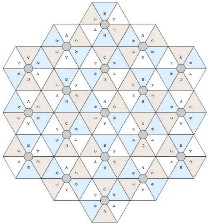
An example for assignment of frequency channels and sector IDs is provided in the following table.
Table 86 Example 5.8 GHz 3-channel assignment by access site
| Symbol | Frequency |
| A 5.740 GHz | |
| B 5.760 GHz | |
| C 5.780 GHz |
Considerations on back-to-back frequency reuse
Cambium Networks recommends using back-to-back (ABAB) frequency reuse, as shown in Figure 52. This means that a base site of four sectors can be created using two frequencies, which works very well and helps define networks in situations where high capacity is required in a limited amount of spectrum.
The conditions necessary to implement this plan are:
• GPS synchronization: all the access points transmit at the same time
- Uplink and Downlink timings across APs do not overlap: they can be adjusted using the frame calculators and co-location tools provided by Cambium
- Uplink power control to ensure that all signals are received on the uplink at the same level: this is automatically enabled on all sectors
- There are no reflecting objects which are too large in the exclusion zones defined in this section.
- The SMs do not normally have line-of-sight (LoS) to an interfering base station. The worst-case range ratio in Figure 52 is 5:1 which in LoS only gives 14 dB protection. Greater than 30 dB is required for 256QAM capability. Down tilt can be used to advantage when the elevation beamwidth is low. Also, the range ratio applies to the longest distance SM, shorter distance SMs have a better range ratio. This frequency reuse plan may not always give 256QAM for the longest distance SMs. It is usually a good compromise between using more spectrum and guaranteed modulation rate.
Reflecting objects
Figure 54 shows two diagrams of the same reflecting object. Uplink interference demonstrates the situation when the two SMs are transmitting at the same time. SM2 should be received cleanly by the AP for Sector 3. At the same time interference can arise from SM1 via the reflecting object and cause a lower Signal-to-Interference ratio than required at AP3. This may either cause transmission errors which are corrected by ARQ or cause the selected modulation rate to be lowered. Either may cause a lower throughput from SM2 and therefore sector 3.
Downlink interference shows the situation when AP3 interferes with SM1. Again, the transmission may be reduced by errors or a reduction in modulation rate.
Figure 54 Reflection
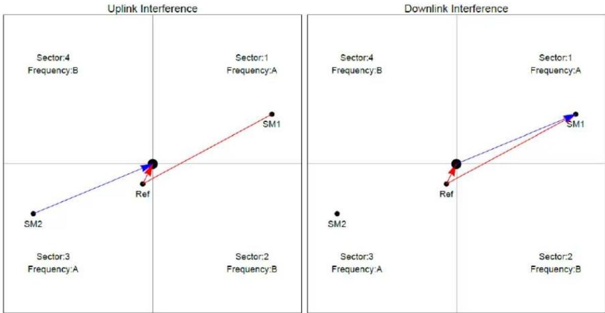
scatter
| Sector | Frequency | Source | Intersection | |--------|-----------|--------|--------------| | SM1 | A | Ref | Point 1 | | SM2 | A | Ref | Point 2 | | SM1 | A | Ref | Point 3 | | SM2 | A | Ref | Point 4 | | SM1 | A | Ref | Point 5 | | SM2 | A | Ref | Point 6 | | SM1 | A | Ref | Point 7 | | SM2 | A | Ref | Point 8 | | SM1 | A | Ref | Point 9 | | SM2 | A | Ref | Point 10 | | SM1 | A | Ref | Point 11 | | SM2 | A | Ref | Point 12 | | SM1 | B | Ref | Point 13 | | SM2 | B | Ref | Point 14 | | SM1 | B | Ref | Point 15 | | SM2 | B | Ref | Point 16 | | SM1 | B | Ref | Point 17 | | SM2 | B | Ref | Point 18 | | SM1 | B | Ref | Point 19 | | SM2 | B | Ref | Point 20 | | SM1 | B | Ref | Point 21 | | SM2 | B | Ref | Point 22 | | SM1 | B | Ref | Point 23 | | SM2 | B | Ref | Point 24 | | SM1 | B | Ref | Point 25 | | SM2 | B | Ref | Point 26 | | SM1 | B | Ref | Point 27 | | SM2 | B | Ref | Point 28 | | SM1 | B | Ref | Point 29 | | SM2 | B | Ref | Point 30 | | SM1 | B | Ref | Point 31 | | SM2 | B | Ref | Point 32 | | SM1 | B | Ref | Point 33 | | SM2 | B | Ref | Point 34 | | SM1 | B | Ref | Point 35 | | SM2 | B | Ref | Point 36 | | SM1 | B | Ref | Point 37 | | SM2 | B | Ref | Point 38 | | SM1 | B | Ref | Point 39 | | SM2 | B | Ref | Point 40 | | SM1 | B | Ref | Point 41 | | SM2 | B | Ref | Point 42 | | SM1 | B | Ref | Point 43 | | SM2 | B | Ref | Point 44 | | SM1 | B | Ref | Point 45 | | SM2 | B | Ref | Point 46 | | SM1 | B | Ref | Point 47 | | SM2 | B | Ref | Point 48 | | SM1 | B | Ref | Point 49 | | SM2 | B | Ref | Point 50 | | SM1 | B | Ref | Point 51 | | SM2 | B | Ref | Point 52 | | SM1 | B | Ref | Point 53 | | SM2 | B | Ref | Point 54 | | SM1 | B | Ref | Point 55 | | SM2 | B | Ref | Point 56 | | SM1 | B | Ref | Point 57 | | SM2 | B | Ref | Point 58 | | SM1 | B | Ref | Point 59 | | SM2 | B | Ref | Point 60 | | SM1 | B | Ref | Point 61 | | SM2 | B | Ref | Point 62 | | SM1 | B | Ref | Point 63 | | SM2 | B | Ref | Point 64 | | SM1 | B | Ref | Point 65 | | SM2 | B | Ref | Point 66 | | SM1 | B | Ref | Point 67 | | SM2 | B | Ref | Point 68 | | SM1 | B | Ref | Point 69 | | SM2 | B | Ref | Point 70 | | SM1 | B | Ref | Point 71 | | SM2 | B | Ref | Point 72 | | SM1 | B | Ref | Point 73 | | SM2 | B | Ref | Point 74 | | SM1 | B | Ref | Point 75 | | SM2 | B | Ref | Point 76 | | SM1 | B | Ref | Point 77 | | SM2 | B | Ref | Point 78 | | SM1 | B | Ref | Point 79 | | SM2 | B | Ref | Point 80 | | SM1 | B | Ref | Point 81 | | SM2 | B | Ref | Point 82 | | SM1 | B | Ref | Point 83 | | SM2 | B | Ref | Point 84 | | SM1 | B | Ref | Point 85 | | SM2 | B | Ref | Point 86 | | SM1 | B | Ref | Point 87 | | SM2 | B | Ref | Point 88 | | SM1 | B | Ref | Point 89 | | SM2 | B | Ref | Point 90 | | SM1 | B | Ref | Point 91 | | SM2 | B | Ref | Point 92 | | SM1 | B | Ref | Point 93 | | SM2 | B | Ref | Point 94 | | SM1 | B | Ref | Point 95 | | SM2 | B | Ref | Point 96 | | SM1 | B | Ref | Point 97 | | SM2 | B | Ref | Point 98 | | SM1 | B | Ref | Point 99 | | SM2 | B | Ref | Point 100 | The plot displays two rows of 'Uplink Interference' and 'Downlink Interference' with 'Source' and 'Frequency' labels for each row. The values for 'Sector' and 'Ref' are estimated based on the y-axis. There are two data series: one for Sector and one for Frequency.Reflection likelihood guidance
As shown in the previous section, reflection can cause a decrease in throughput in an ABAB base site. This section provides guidance on whether a reflection is likely to cause interference. The first condition for whether a reflection can cause the data rate to reduce is that the reflecting object must be in view of the AP and the SM to re-transmit the signal. If this is not the case, then the object cannot cause interference.
Given that the potential reflecting object is seen by the AP and the SM, there are a range of object sizes and a range of zones where we can predict that interference will occur which may reduce the throughput when both sector 1 and sector 3 are carrying traffic.
Figure 55 and Figure 56 show regions enumerated A, B, C, and D. We also need to consider objects of size 1, 2, 3 and 4 and define the areas where the objects may interfere.
- object size 1: a flat building face with a clear reflecting property from sector to AP
- object size 2: random metalwork such as a wireless tower
- object size 3: a 0.5 × 0.5m flat metallic face or tree
- object size 4: a 0.2 × 0.2m random metal structure or 0.5 × 0.5m foliage.
The conditions for no interference are:
- size 2 outside zone B
- size 3 outside zone C
- size 4 outside zone D
The size 1 object can interfere at large distances. It is necessary to look at the geometry by which reflection could occur and cause interference. Typically, this will occur at a restricted range of azimuths and ranges.
Figure 55 Sector Antenna

contour
| Zone | x (m) | y (m) | |------|-------|-------| | A | 48.0 | -4.0 | | B | 32.0 | -2.0 | | C | 12.0 | -2.0 | | D | 2.0 | -2.0 |
radar
| Category | Value | | ------------------ | ----- | | Zero Azimuth | 0 | | Direction of Reflector | -10 | | Other Regions | 0 |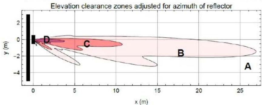
contour
| Point | x (m) | y (m) | |-------|-------|-------| | A | 25 | -1 | | B | 18 | -1 | | C | 7 | 0 | | D | 0 | 0 |Figure 56 cnMedusa Antenna
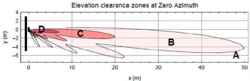
line
| Point | x (m) | y (m) | |-------|-------|-------| | A | 45 | -4 | | B | 30 | -2 | | C | 15 | -2 | | D | 0 | -2 |
scatter
| x (m) | y (m) | Region | |-------|-------|------------------| | 0 | 0 | Zero Azimuth | | 10 | -10 | Direction of Reflector | | 20 | 0 | Zero Azimuth | | 30 | 20 | Zero Azimuth | | 40 | 20 | Zero Azimuth | | 50 | 20 | Zero Azimuth |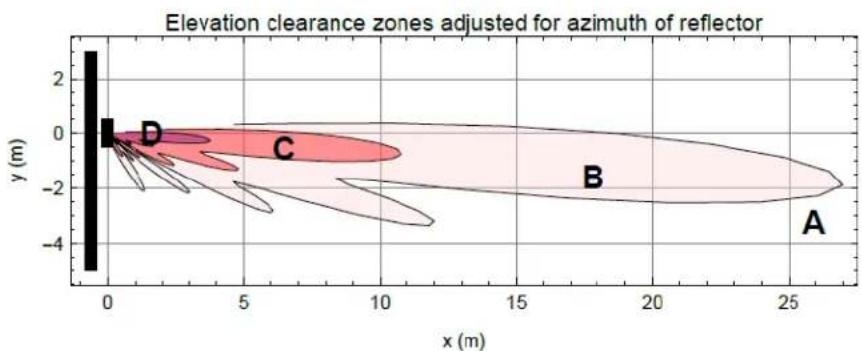
contour
| Point | x (m) | y (m) | |-------|-------|-------| | A | 26.0 | -2.0 | | B | 18.0 | -1.0 | | C | 7.0 | -1.0 | | D | 1.0 | -1.0 |Figure 55 and Figure 56 each have three diagrams scaled in meters where Figure 55 is for the sector antenna and Figure 56 is for cnMedusa. In each figure the distances and heights assume a typical down tilt of 4^ .
In each figure the top diagram represents the clearances required at zero azimuth. The middle diagram represents the scaling required to the top diagram to allow for differences in azimuth of the considered reflecting object. The bottom diagram is the scaled version of the top diagram allowing for the dotted azimuth line in the middle diagram.
PMP 450m Series AP is based on Massive MU-MIMO technology. The 5GHz 450m is a 14x14 MIMO system which allows simultaneous communication to up to seven SMs. The 3GHz 450m is an 8x8 MIMO system which allows simultaneous communication to up to four SMs.
Figure 57 PMP 450m Series AP antenna beam

natural_image
Illustration of a fan with colorful light beams pointing outward from a black object, no text or symbols present.PMP 450m installation recommendations
- For best performance it is recommended to have a clearance zone around the mast. The clearance zone depends on the surrounding environment and the antenna's down tilt. If the mast is surrounded by metal, then larger clearance is required compared to an environment where the antenna is surrounded by foliage
• SMs should be spread in azimuth of AP antenna
- 450m is susceptible to movement, for best MU-MIMO performance it is recommended that the 450m AP is mounted/installed on a mast that is extremely rigid (no movement and is vertical).
• LINKPlanner can be used to plan SMs across the AP antenna azimuth
Link planning
This section describes factors to be considered when planning links, such as range, obstacles path loss and throughput. LINKPlanner is recommended.
Range and obstacles
Calculate the range of the link and identify any obstacles that may affect radio performance.
Perform a survey to identify all the obstructions (such as trees or buildings) in the path and to assess the risk of interference. This information is necessary in order to achieve an accurate link feasibility assessment.
The 450 Platform Family is designed to operate in Non-Line-of-Sight (NLoS) and Line-of-Sight (LoS) environments. An NLOS environment is one in which there is no optical line-of-sight, that is, there are obstructions between the antennas.
OFDM technology can often use multi-pathing to an advantage to overcome nLOS, especially in cases where the Fresnel zone is only partially blocked by buildings, “urban canyons”, or foliage. OFDM tends to help especially when obstacles are near the middle of the link, and less so when the obstacles are very near the ODU.
However, attenuation through walls and trees is substantial for any use of the 5.4 GHz and 5.8 GHz frequency bands. The lower frequency radio waves of 900 MHz radios provide greater penetration through walls, trees and other obstacles, making it optimal for most non-line-of-sight applications. Even with OFDM, these products are not expected to penetrate walls or extensive trees and foliage.
Path loss
Path loss is the amount of attenuation the radio signal undergoes between the two ends of the link. The path loss is the sum of the attenuation of the path if there were no obstacles in the way (Free Space Path Loss), the attenuation caused by obstacles (Excess Path Loss) and a margin to allow for possible fading of the radio signal (Fade Margin). The following calculation needs to be performed to judge whether a link can be installed:
$$ + \quad_ {e x c e s s s p a c e f r e e} + L L L \notin L \quad L _ {\text { capability }} $$
Where: Is:
$$ \begin{array}{l} L _ {f r e e _ s p a c e} \quad \text { Free Space Path Loss(dB) } \ L _ {\text { excess }} \quad \text { Excess Path Loss(dB) } \ L _ {f a d e} \quad \text { Fade Margin Required (dB) } \ L _ {\text { seasonal }} \quad \text { Seasonal Fading(dB) } \ \end{array} $$
L_capability
Equipment Capability (dB)
Calculating Link Loss
The link loss is the total attenuation of the wireless signal between two point-to-multipoint units. The link loss calculation is presented below:
Link Loss (dB) = Transmit power of the remote wireless unit (dBm) - Tx Cable loss (dB) - Received power at the local unit (dBm) - Rx cable loss (dB) + Antenna gain at the remote unit (dBi) + Antenna gain at the local unit (dBi)
Calculating Rx Signal Level
The determinants in Rx signal level are illustrated in Figure 58.
Figure 58 Determinants in Rx signal level

flowchart
graph LR
    A["Transmitter"] -->|Tx power| B["Tx power"]
    B --> C["Tx cable loss"]
    C --> D["Tx antenna gain"]
    D --> E["Rx antenna gain"]
    E --> F["Rx signal level"]
    F --> G["Receiver"]
    style A fill:#f9f,stroke:#333
    style G fill:#bbf,stroke:#333
    note right of D: free space signal
    note left of E: distance
Rx signal level is calculated as follows:
Rx signal level dB = Tx power - Tx cable loss + Tx antenna gain - free space path loss + Rx antenna gain - Rx cable loss

Note
This Rx signal level calculation presumes that a clear line of sight is established between the transmitter and receiver and that no objects encroach in the Fresnel zone.
Calculating Fade Margin
Free space path loss is a major determinant in Rx (received) signal level. Rx signal level, in turn, is a major factor in the system operating margin (fade margin), which is calculated as follows:
System operating margin (fade margin) dB = Rx signal level dB - Rx sensitivity dB
Thus, fade margin is the difference between strength of the received signal and the strength that the receiver requires for maintaining a reliable link. A higher fade margin is characteristic of a more reliable link.
Adaptive modulation
Adaptive modulation ensures that the highest throughput that can be achieved instantaneously will be obtained, taking account of propagation and interference. When the link has been installed, web pages provide information about the link loss currently measured by the equipment, both instantaneously and averaged. The averaged value will require maximum seasonal fading to be added, and then the radio reliability of the link can be computed.
For details of the system throughput, link loss and maximum distance for each frequency band in all modulation modes, see Link on page 10-56.
Planning for connectorized units
This section describes factors to be considered when planning to use connectorized ODUs with external antennas in 450 Platform Family links.
When to install connectorized units
Most of radio links can be successfully deployed with the integrated ODU. However, the integrated units may not be sufficient in some areas, for example:
• Where the path is heavily obscured by dense woodland on an NLOS link.
• Where long LOS links are required.
• Where there are known to be high levels of interference.
In these areas, connectorized ODUs and external antennas should be used.
Choosing external antennas
When selecting external antennas, consider the following factors:
- The required antenna gain.
- Ease of mounting and alignment.
• Use dual-polarization antenna (as the integrated antenna).

Note
Enter the antenna gain and cable loss into the Installation Wizard, if the country selected has an EIRP limit, the corresponding maximum transmit power will be calculated automatically by the unit.
Calculating RF cable length (5.8 GHz FCC only)
The 5.8 GHz band FCC approval for the product is based on tests with a cable loss between the ODU and antenna of not less than 1.2 dB. If cable loss is below 1.2 dB with a 1.3 m (4 ft) diameter external antenna, the connectorized 450 Platform Family may exceed the maximum radiated spurious emissions allowed under FCC 5.8 GHz rules.
Cable loss depends mainly upon cable type and length. To meet or exceed the minimum loss of 1.2 dB, use cables of the type and length specified in Table 87 (source: Times Microwave). This data excludes connector losses.
Table 87 RF cable lengths required to achieve 1.2 dB loss at 5.8 GHz
| RF cable type | Minimum cable length |
| LMR100 0.6 m (1.9 ft) | |
| LMR200 1.4 m (4.6 ft) | |
| LMR300 2.2 m (7.3 ft) | |
| LMR400 3.4 m (11.1 ft) | |
| LMR600 5.0 m (16.5 ft) |
Data network planning
This section describes factors to be considered when planning 450 Platform Family data networks.
Understanding addresses
A basic understanding of Internet Protocol (IP) address and subnet mask concepts is required for engineering your IP network.
IP address
The IP address is a 32-bit binary number that has four parts (octets). This set of four octets has two segments, depending on the class of IP address. The first segment identifies the network. The second identifies the hosts or devices on the network. The subnet mask marks a boundary between these two sub-addresses.
Dynamic or static addressing
For any computer to communicate with a module, the computer must be configured to either
- use DHCP (Dynamic Host Configuration Protocol). In this case, when not connected to the network, the computer derives an IP address on the 169.254 network within two minutes.
• have an assigned static IP address (for example, 169.254.1.5) on the 169.254 network.

Note
If an IP address that is set in the module is not the 169.254.x.x network address, then the network operator must assign the computer a static IP address in the same subnet.
When a DHCP server is not found
To operate on a network, a computer requires an IP address, a subnet mask, and possibly a gateway address. Either a DHCP server automatically assigns this configuration information to a computer on a network or an operator must input these items.
When a computer is brought on line and a DHCP server is not accessible (such as when the server is down or the computer is not plugged into the network), Microsoft and Apple operating systems default to an IP address of 169.254.x.x and a subnet mask of 255.255.0.0 (169.254/16, where /16 indicates that the first 16 bits of the address range are identical among all members of the subnet).
DNS Client
The DNS Client is used to resolve names of management servers within the operator's management domain (see Figure 59). This feature allows hostname configuration for NTP servers, Authorization Servers, DHCP relay servers, and SNMP trap servers. Operators may choose to either enter in the FQDN (Fully Qualified Domain Name) for the host name or to manually enter the IP addresses of the servers.
Figure 59 Cambium networks management domain

flowchart
graph TD
    A["AP"] --> B["SM"]
    C["NTP Svr"] --> D["SNMP Mgr"]
    E["DNS Svr"] --> F["Auth Svr"]
    G["DHCP Svr"] --> H["Management Domain"]
    I["Cloud"] --> A
    style A fill:#f9f,stroke:#333
    style B fill:#ccf,stroke:#333
    style C fill:#cfc,stroke:#333
    style D fill:#fcc,stroke:#333
    style E fill:#cff,stroke:#333
    style F fill:#ffc,stroke:#333
    style G fill:#fcc,stroke:#333
    style H fill:#cfc,stroke:#333
    style I fill:#fcc,stroke:#333
Network Address Translation (NAT)
NAT, DHCP Server, DHCP Client and DMZ in SM
The system provides NAT (network address translation) for SMs in the following combinations of NAT and DHCP (Dynamic Host Configuration Protocol):
- NAT Disabled
- NAT with DHCP Client (DHCP selected as the Connection Type of the WAN interface) and DHCP Server
• NAT with DHCP Client (DHCP selected as the Connection Type of the WAN interface)
• NAT with DHCP Server - NAT without DHCP
NAT
NAT isolates devices connected to the Ethernet/wired side of a SM from being seen directly from the wireless side of the SM. With NAT enabled, the SM has an IP address for transport traffic (separate from its address for management), terminates transport traffic, and allows you to assign a range of IP addresses to devices that are connected to the Ethernet/wired side of the SM.
In the Cambium system, NAT supports many protocols, including HTTP, ICMP (Internet Control Message Protocols), and FTP (File Transfer Protocol). For virtual private network (VPN) implementation, L2TP over IPSec (Level 2 Tunneling Protocol over IP Security) and PPTP (Point to Point Tunneling Protocol) are supported.
DHCP
DHCP enables a device to be assigned a new IP address and TCP/IP parameters, including a default gateway, whenever the device reboots. Thus DHCP reduces configuration time, conserves IP addresses, and allows modules to be moved to a different network within the Cambium system.
In conjunction with the NAT features, each SM provides:
- A DHCP server that assigns IP addresses to computers connected to the SM by Ethernet protocol.
- A DHCP client that receives an IP address for the SM from a network DHCP server.
DMZ
In conjunction with the NAT features, a DMZ (demilitarized zone) allows the assignment of one IP address behind the SM for a device to logically exist outside the firewall and receive network traffic. The first three octets of this IP address must be identical to the first three octets of the NAT private IP address.
Developing an IP addressing scheme
Network elements are accessed through IP Version 4 (IPv4) addressing.
A proper IP addressing method is critical to the operation and security of a network.
Each module requires an IP address on the network. This IP address is for only management purposes. For security, you must either:
- Assign a non-routable IP address.
- Assign a routable IP address only if a firewall is present to protect the module.
You assign an IP addresses to computers and network components by either static or dynamic IP addressing. You will also assign the appropriate subnet mask and network gateway to each module.
Address Resolution Protocol
As previously stated, the MAC address identifies a module in:
- Communications between modules.
• The data that modules store about each other.
The IP address is essential for data delivery through a router interface. Address Resolution Protocol (ARP) correlates MAC addresses to IP addresses.
For communications to outside the network segment, ARP reads the network gateway address of the router and translates it into the MAC address of the router. Then the communication is sent to MAC address (physical network interface card) of the router.
For each router between the sending module and the destination, this sequence applies. The ARP correlation is stored until the ARP cache times out.
Allocating subnets
The subnet mask is a 32-bit binary number that filters the IP address. Where a subnet mask contains a bit set to 1, the corresponding bit in the IP address is part of the network address.
Example IP address and subnet mask
In Figure 60, the first 16 bits of the 32-bit IP address identify the network:
Figure 60 Example of IP address in Class B subnet
| Octet 1 | Octet 2 | Octet 3 | Octet 4 | |
| IP address 169.254.1.1 | 10101001 | 11111110 | 00000001 | 00000001 |
| Subnet mask 255.255.0.0 | 11111111 | 11111111 | 00000000 | 00000000 |
In this example, the network address is 169.254 and 2^16 (65,536) hosts are addressable.
Selecting non-routable IP addresses
The factory default assignments for network elements are:
- Unique MAC address
• IP address of 169.254.1.1 - Subnet mask of 255.255.0.0
• Network gateway address of 169.254.0.0
For each radio and CMM4, assign an IP address that is both consistent with the IP addressing plan for your network and cannot be accessed from the Internet. IP addresses within the following ranges are not routable from the Internet, regardless of whether a firewall is configured:
• 10.0.0.0 - 10.255.255.255
• 172.16.0.0 - 172.31.255.255
• 192.168.0.0 - 192.168.255.255
Also, the subnet mask and network gateway for each CMM4 can be assigned.
Translation bridging
Optionally, the AP can be configured to change the source MAC address in every packet it receives from its SMs to the MAC address of the SM/BHS that bridged the packet, before forwarding the packet toward the public network. In this case:
- Not more than 128 IP devices at any time are valid to send data to the AP from behind the SM.
- SM populates the Translation Table tab of its Statistics web page, displaying the MAC address and IP address of all the valid connected devices.
-
Each entry in the Translation Table is associated with the number of minutes that have elapsed since the last packet transfer between the connected device and the SM.
• If 128 are connected, and another attempt to connect: -
If no Translation Table entry is older than 255 minutes, the attempt is ignored.
○ If an entry is older than 255 minutes, the oldest entry is removed and the attempt is successful.
- The Send Untranslated ARP parameter in the General tab of the Configuration page can be:
- Disabled, so that the AP overwrites the MAC address in ARP packets before forwarding them.
- Enabled, so that the AP forwards ARP packets regardless of whether it has overwritten the MAC address.
This is the Translation Bridging feature, which you can enable in the General page of the Configuration web page in the AP. When this feature is disabled, the setting of the Send Untranslated ARP parameter has no effect, because all packets are forwarded untranslated (with the source MAC address intact). See Address Resolution Protocol on Page 3-36.
Engineering VLANs
The radios support VLAN functionality as defined in the 802.1Q (Virtual LANs) specification, except for the following aspects of that specification:
- Protocols:
o Generic Attribute Registration Protocol (GARP) GARV
○ Spanning Tree Protocol (STP)
o Multiple Spanning Tree Protocol (MSTP)
o GARP Multicast Registration Protocol (GMRP)
- Embedded source routing (ERIF) in the 802.1Q header
- Multicast pruning
- Flooding unknown unicast frames in the downlink
As an additional exception, the AP/BHM does not flood downward the unknown unicast frames to the SM/BHS.
A VLAN configuration in Layer 2 establishes a logical group within the network. Each computer in the VLAN, regardless of initial or eventual physical location, has access to the same data. For the network operator, this provides flexibility in network segmentation, simpler management, and enhanced security.
Special case VLAN numbers
This system handles special case VLAN numbers according to IEEE specifications:
Table 88 Special case VLAN IDs
| VLAN Number | Purpose | Usage Constraint |
| 0 | These packets have 802.1p priority, but are otherwise handled as untagged. | Must not be used as a management VLAN. |
| 1 | Although not noted as special case by IEEE specifications, these packets identify traffic that was untagged upon ingress into the SM and must remain untagged upon egress. This policy is hard-coded in the AP. | Must not be used for system VLAN traffic. |
| 4095 | This VLAN is reserved for internal use. | Must not be used at all. |
SM membership in VLANs
With the supported VLAN functionality, the radios determine bridge forwarding on the basis of not only the destination MAC address, but also the VLAN ID of the destination. This provides flexibility in how SMs are used:
• Each SM can be a member in its own VLAN.
- Each SM can be in its own broadcast domain, such that only the radios that are members of the VLAN can see broadcast and multicast traffic to and from the SM.
- The network operator can define a work group of SMs, regardless of the AP(s) to which they register.
PMP 450 Platform Family modules provide the VLAN frame filters that are described in Table 89.
Table 89 VLAN filters in point-to-multipoint modules
| Where VLAN is active, if this parameter value is selected ... | then a frame is discarded if... | because of this VLAN filter in the software: | |
| entering the bridge/NAT switch through... | |||
| Ethernet... | TCP/IP... | ||
| any combination of VLAN parameter settings | with a VID not in the membership table | Ingress | |
| any combination of VLAN parameter settings | with a VID not in the membership table | Local Ingress | |
| Allow Frame Types: Tagged Frames Only | with no 802.1Q tag | Only Tagged | |
| Allow Frame Types: Untagged Frames Only | with an 802.1Q tag, regardless of VID | Only Untagged | |
| Local SM Management: Disable in the SM, or All Local SM Management: Disable in the AP | with an 802.1Q tag and a VID in the membership table | Local SM Management | |
| leaving the bridge/NAT switch through... | |||
| Ethernet... | TCP/IP... | ||
| any combination of VLAN parameter settings | with a VID not in the membership table | Egress | |
| any combination of VLAN parameter settings | with a VID not in the membership table | Local Egress | |
Priority on VLANs (802.1p)
The radios can prioritize traffic based on the eight priorities described in the IEEE 802.1p specification. When the high-priority channel is enabled on a SM, regardless of whether VLAN is enabled on the AP for the sector, packets received with a priority of 4 through 7 in the 802.1p field are forwarded onto the high-priority channel.
For example, when the high priority and low priority channels are enabled on an SM, medium and ultra high priority channels are disabled.
Operators may configure priority precedence as 802.1p Then Diffserv (Default) or Diffserv Then 802.1p. Since these priority precedence configurations are independent between the AP and SM, this setting must be configured on both the AP and SM to ensure that the precedence is adhered to by both sides of the link.
VLAN settings can also cause the module to convert received non-VLAN packets into VLAN packets. In this case, the 802.1p priority in packets leaving the module is set to the priority established by the DiffServ configuration.
If VLAN is enabled, immediately monitor traffic to ensure that the results are as desired. For example, high-priority traffic may block low-priority.
Q-in-Q DVLAN (Double-VLAN) Tagging (802.1ad)
PMP and PTP modules can be configured with 802.1ad Q-in-Q DVLAN (Double-VLAN) tagging which is a way for an operator to put an 802.1Q VLAN inside of an 802.1ad VLAN. A nested VLAN, which is the original 802.1Q tag and a new second 802.1ad tag, allows for bridging of VLAN traffic across a network and segregates the broadcast domains of 802.1Q VLANs. Q-in-Q can be used with PPPoE and/or NAT.
The 802.1ad standard defines the S-VLAN as the Service Provider VLAN and the C-VLAN as the customer VLAN. The radio software does 2-layer Q-in-Q whereby the C-VLAN is the 802.1Q tag and the S-VLAN is the second layer Q tag as shown in Table 90.
Table 90 Q-in-Q Ethernet frame
| Ethernet Header | S-VLANEthType 0x88a8 | C-VLANEthType 0x8100 | IP Data EthType 0x0800 |
The 802.1ad S-VLAN is the outer VLAN that is configurable on the Configuration > VLAN web page of the AP/BHM. The Q-in-Q EtherType parameter is configured with a default EtherType of 0x88a8 in addition to four alternate EtherTypes that can be configured to aid in interoperability with existing networks that use a different EtherType than the default.
The C-VLAN is the inner VLAN tag, which is the same as 802.1Q. As a top-level concept, this operates on the outermost tag at any given time, either “pushing” a tag on or “popping” a tag off. This means packets will at most transition from an 802.1Q frame to an 801.ad frame (with a tag “pushed” on) or an untagged 802.1 frame (with the tag “popped” off. Similarly, for an 802.1ad frame, this can only transition from an 802.1ad frame to an 802.1Q frame (with the tag “popped” off) since the radio software only supports 2 levels of tags.
Network management planning
This section describes how to plan for 450 Platform Family links to be managed remotely using SNMP.
Planning for SNMP operation
Cambium modules provide the following SNMP traps for automatic notifications to the NMS:
- coldStart, which signals that the SNMPv2c element is reinitializing itself and that its configuration may have been altered.
- warmStart, which signals that the SNMPv2c element is reinitializing such that its configuration is unaltered.
- authenticationFailure, which signals that the SNMPv2c element has received a protocol message that is not properly authenticated (contingent on the snmpEnableAuthenTraps object setting).
- linkDown, as defined in RFC 1573
- linkUp, as defined in RFC 1573
• egpNeighborLoss, as defined in RFC 1213 - whispGPSInSync, which signals a transition from not synchronized to synchronized.
- whispGPSOutSync, which signals a transition from synchronized to not synchronized.
- whispRegComplete, which signals registration completed.
• whispRegLost, which signals registration lost. - whispRadarDetected, which signals that the one-minute scan has been completed, radar has been detected and the radio will shut down.
- whispRadarEnd, which signals that the one-minute scan has been completed, radar has not been detected and the radio will resume normal operation.

Note
The proprietary MIBs are provided in the 450 Platform Family software download files in the support website (see Contacting Cambium Networks on page 1).
Enabling SNMP
Enable the SNMP interface for use by configuring the following attributes in the SNMP Configuration page:
• SNMP State (default disabled)
• SNMP Version (default SNMPv2c)
• SNMP Port Number (default 161)
Security planning
This section describes how to plan for 450 Platform Family links to operate in secure mode.
• Managing module access by passwords
• Filtering protocols and ports
- Port Configuration
Isolating AP/BHM from the Internet
Ensure that the IP addresses of the AP/BHM in the network:
- are not routable over the Internet.
• do not share the subnet of the IP address of your user.
RFC 1918, Address Allocation for Private Subnets, reserves for private IP networks three blocks of IP addresses that are not routable over the Internet:
• /8 subnets have one reserved network, 10.0.0.0 to 10.255.255.255.
• /16 subnets have 16 reserved networks, 172.16.0.0 to 172.31.255.255.
• /24 subnets have 256 reserved networks, 192.168.0.0 to 192.168.255.255.
Encrypting radio transmissions
Cambium fixed wireless broadband IP systems employ the following form of encryption for security of the wireless link:
AES (Advanced Encryption Standard): An over-the-air link encryption option that uses the Rijndael algorithm and 128-bit keys to establish a higher level of security than DES. AES products are certified as compliant with the Federal Information Processing Standards (FIPS 197) in the U.S.A.
The default encryption setting for 450 Platform Family ODU is "None".
Planning for HTTPS operation
Before starting to configure HTTPS operation, ensure that the cryptographic material listed in Table 91 is available.
Table 91 HTTPS security material
| Item | Description | Quantity required |
| User Defined Security Banner | The banner provides warnings and notices to be read by the user before logging in to the ODU. Use text that is appropriate to the network security policy. | Normally one per link.This depends upon network policy. |
| Port numbers for HTTP, HTTPS and Telnet | Port numbers allocated by the network. | As allocated by network. |
Planning for SNMPv3 operation
SNMP security mode
Decide how SNMPv3 security will be configured.
MIB-based security management uses standard SNMPv3 MIBs to configure the user-based security model and the view-based access control model. This approach provides considerable flexibility, allowing a network operator to tailor views and security levels appropriate for different types of user. MIB-based security management may allow a network operator to take advantage of built-in security management capabilities of existing network managers.
Web-based security management allows an operator to configure users, security levels, privacy and authentication protocols, and passphrases using the 450 Platform Family web-based management interface. The capabilities supported are somewhat less flexible than those supported using the MIB-based security management, but will be sufficient in many applications. Selection of web-based management for SNMPv3 security disables the MIB-based security management. 450 Platform Family does not support concurrent use of MIB-based and web-based management of SNMPv3 security.
Web-based management of SNMPv3 security
Initial configuration of SNMPv3 security is available only to HTTP or HTTPS user accounts with security role of Security Officer.
Identify the format used for SNMP Engine ID. The following formats are available:
• MAC address (default)
- 5 and 32 hex characters (the hex character input is driven by RFC 3411 recommendations on the Engine ID)
Identify the user names and security roles of initial SNMPv3 users. Two security roles are available:
- Read Only
- System Administrator
Identify the security level for each of the security roles. Three security levels are available:
(a) No authentication, no privacy
(b) Authentication, no privacy
(c) Authentication, privacy
If authentication is required, identify the protocol. The authentication protocol available is MD5.
If privacy will be used, identify the protocol. The privacy protocol available is cbc-des.
Managing module access by passwords
From the factory, each module has a preconfigured administrator-level account in the name root, which initially requires no associated password. When you upgrade a module:
• An account is created in the name admin.
- Both admin and root inherit the password that was previously used to access the module, if:
- Full Access password, if one was set.
○ Display-Only Access password, if one was set and no Full Access password was set.

Caution
If you use Wireless Manager, do not delete the root account from any module. If you use a NMS that communicates with modules through SNMP, do not delete the root account from any module unless you first can confirm that the NMS does not rely on the root account for access to the modules.
Each module supports four or fewer user accounts, regardless of account levels. The available levels are
- ADMINISTRATOR, who has full read and write permissions. This is the level of the root and admin users, as well as any other administrator accounts that one of them creates.
- INSTALLER, who has permissions identical to those of ADMINISTRATOR except that the installer cannot add or delete users or change the password of any other user.
- TECHNICIAN, who has permissions to modify basic radio parameters and view informational web pages.
• GUEST, who has no write permissions and only a limited view of General Status tab. - Admin, Installer and Tech accounts can be configured as READ-ONLY. This will allow the account to only see the items.
The ability to view information of General Status tab can be controlled by the "Site Information Viewable to Guest Users" under the SNMP tab.
From the factory default state, configure passwords for both the root and admin account at the ADMINISTRATOR permission level, using the Account > Change Users Password page. (If configure only one of these, then the other will still require no password for access into it and thus remain a security risk.) If you are intent on configuring only one of them, delete the admin account. The root account is the only account that CNUT uses to update the module.
After a password has been set for any ADMINISTRATOR-level account, initial access to the module GUI opens the view of GUEST level.
Planning for RADIUS operation
Configure RADIUS where remote authentication is required for users of the web-based interface. Remote authentication has the following advantages:
• Control of passwords can be centralized.
- Management of user accounts can be more sophisticated. For example; users can be prompted by a network manager to change passwords at regular intervals. As another example, passwords can be checked for inclusion of dictionary words and phrases.
- Passwords can be updated without reconfiguring multiple network elements.
- User accounts can be disabled without reconfiguring multiple network elements.
Remote authentication has one significant disadvantage in a wireless link product such as 450 Platform Family. If the wireless link is down, a unit on the remote side of the broken link may be prevented from contacting a RADIUS Server, with the result that users are unable to access the web-based interface.
One useful strategy would be to combine RADIUS authentication for normal operation with a single locally-authenticated user account for emergency use.
PMP 450 Platform Family SM provides a choice of the following authentication methods:
- Phase 1:
Ensure that the authentication method selected in 450 Platform Family is supported by the RADIUS server.
Filtering protocols and ports
Configure filters for specified protocols and ports from leaving the AP/BHM and SM/BHS and entering the network. This protects the network from both intended and inadvertent packet loading or probing by network users. By keeping the specified protocols or ports off the network, this feature also provides a level of protection to users from each other.
Protocol and port filtering is set per AP/SM/BH. Except for filtering of SNMP ports, filtering occurs as packets leave the AP/SM/BH.
For example, if SM is configured to filter SNMP, then SNMP packets are blocked from entering the SM and, thereby, from interacting with the SNMP portion of the protocol stack on the SM.
Port Filtering with NAT Enabled
Where NAT is enabled on the SM/BHS, the filtering can be enabled for only the user-defined ports. The following are examples for situations where the configure port can be filtered where NAT is enabled:
- To block a subscriber from using FTP, you can filter Ports 20 and 21 (the FTP ports) for both the TCP and UDP protocols.
- To block a subscriber from access to SNMP, you can filter Ports 161 and 162 (the SNMP ports) for both the TCP and UDP protocols.

Note
In only the SNMP case, filtering occurs before the packet interacts with the protocol stack.
Protocol and Port Filtering with NAT Disabled
Where NAT is disabled on the SM/BHS, the filtering can be enabled for both protocols and the three user-defined ports. Using the check boxes on the interface, it can be either:
- Allow all protocols except those that user wish to block.
- Block all protocols except those that user wish to allow.
Allow or block any of the following protocols:
- PPPoE (Point to Point Protocol over Ethernet)
• Any or all the following IPv4 (Internet Protocol version 4) protocols:
o SMB (Network Neighborhood) - SNMP
- Bootp Client
- Bootp Server
o Up to 3 user-defined ports - All other IPv4 traffic (see Figure 29)
• Any or all of the following IPv6 (Internet Protocol version 6) protocols:
o SMB (Network Neighborhood)
o SNMP
- Bootp Client
- Bootp Server
- Up to 3 user-defined ports
o All other IPv6 traffic (see Figure 29)
• Filter Direction - Upstream and Downstream
• ARP (Address Resolution Protocol)
Figure 61 Categorical protocol filtering
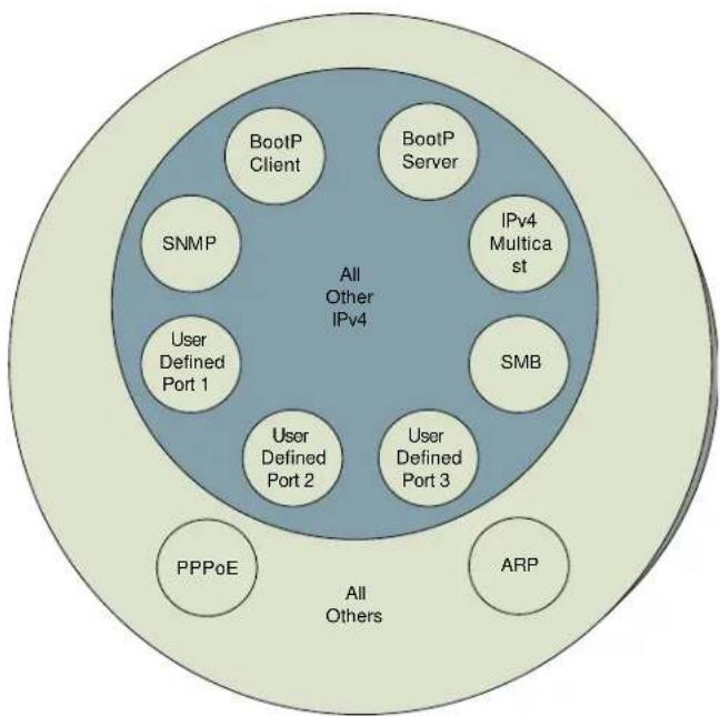
flowchart
graph TD
    A["All Other IPv4"] --> B["BootP Client"]
    A --> C["BootP Server"]
    A --> D["SNMP"]
    A --> E["User Defined Port 1"]
    A --> F["User Defined Port 2"]
    A --> G["User Defined Port 3"]
    A --> H["SMB"]
    A --> I["APPoE"]
    A --> J["ARP"]
    style A fill:#cccccc,stroke:#333
    style B fill:#d4edda,stroke:#333
    style C fill:#d4edda,stroke:#333
    style D fill:#d4edda,stroke:#333
    style E fill:#d4edda,stroke:#333
    style F fill:#d4edda,stroke:#333
    style G fill:#d4edda,stroke:#333
    style H fill:#d4edda,stroke:#333
    style I fill:#d4edda,stroke:#333
    style J fill:#d4edda,stroke:#333
The following are example situations in which the protocol filtering is configured where NAT is disabled:
- If a subscriber is blocked from only PPPoE and SNMP, then the subscriber retains access to all other protocols and all ports.
- If PPPoE, IPv4, and Uplink Broadcast are blocked, and check the All others selection, then only Address Resolution Protocol is not filtered.
The ports filtered because of protocol selections in the Protocol Filtering tab of the SM/BHS are listed in Table 92.
Table 92 Ports filtered per protocol selections
| Protocol Selected | Port Filtered (Blocked) |
| SMB | Destination Ports UDP: 137, 138, 139, 445, 3702 and 1900Destination Ports TCP: 137, 138, 139, 445, 2869, 5357 and 5358 |
| SNMP | Destination Ports TCP and UDP: 161 and 162 |
| Bootp Client | Source Port 68 UDP |
| Bootp Server | Source Port 67 UDP |
| User Defined Port 1..3 | User defined ports for filtering UDP and TCP |
| IPv4 Multicast | Block IPv4 packet types except other filters defined |
| IPv6 Multicast | Block IPv6 packet types except other filters defined |
| ARP | Filter all Ethernet packet type 806 |
| Upstream | Applies packet filtering to traffic coming into the FEC interface |
| Downstream | Applies packet filtering to traffic destined to exit the FEC interface |
Port Configuration
450 Platform Family supports access to various communication protocols and only the ports required for these protocols are available for access by external entities. Operators may change the port numbers for these protocols via the radio GUI or SNMP.
Table 93 Device default port numbers
| Port | Usage | Port Usage | Device |
| 21 | FTP | Listen Port | AP, SM |
| 80 | HTTP | Listen Port | AP, SM |
| 443 | HTTPS | Listen Port | AP, SM |
| 161 | SNMP port | Listen Port | AP, SM |
| 162 | SNMP trap port | Destination Port | AP, SM |
| 514 | Syslog Server port | Destination Port | AP, SM |
| 1812 | Standard RADIUS port | Destination Port | AP |
| 1813 | Standard RADIUS accounting port | Destination Port | AP, SM |
Encrypting downlink broadcasts
An AP can be enabled to encrypt downlink broadcast packets such as the following:
- ARP
- NetBIOS
- broadcast packets containing video data on UDP.
The encryption used is AES for an AES-configured module. Before the Encrypt Downlink Broadcast feature is enabled on the AP, air link security must be enabled on the AP.
Isolating SMs in PMP
In an AP, SMs in the sector can be prevented from directly communicating with each other. In CMM4, the connected APs can be prevented from directly communicating with each other, which prevents SMs that are in different sectors of a cluster from communicating with each other.
In the AP, the SM Isolation parameter is available in the General tab of the Configuration web page. Configure the SM Isolation feature by any of the following selections from drop-down menu:
- Disable SM Isolation (the default selection). This allows full communication between SMs.
- Enable Option 1 - Block SM destined packets from being forwarded. This prevents both multicast/broadcast and unicast SM-to-SM communication.
- Enable Option 2 - Forward SM destined packets upstream. This not only prevents multicast/broadcast and unicast SM-to-SM communication but also sends the packets, which otherwise may have been handled SM to SM, through the Ethernet port of the AP.
In the CMM and the CMM4, SM isolation treatment is the result of how to manage the port-based VLAN feature of the embedded switch, where all traffic can be switched from any AP to a specified uplink port. However, this is not packet level switching. It is not based on VLAN IDs.
Filtering management through Ethernet
Configure the SM to disallow any device that is connected to its Ethernet port from accessing the IP address of the SM. If the Ethernet Access Control parameter is set to Enabled, then:
- No attempt to access the SM management interface (by http, SNMP, ftp, or tftp) through Ethernet is granted.
- Any attempt to access the SM management interface over the air (by IP address, presuming that LAN1 Network Interface Configuration, Network Accessibility is set to Public, or by link from the Session Status or Remote Subscribers tab in the AP) is unaffected.
Allowing management from only specified IP addresses
The Security sub-menu of the Configuration web page in the AP/BHM and SM/BHS includes the IP Access Control parameter. Specify one, two, or three IP addresses that must be allowed to access the management interface (by HTTP, SNMP, FTP or TFTP).
If the selection is:
- IP Access Filtering Disabled, then management access is allowed from any IP address, even if the Allowed Source IP 1 to 3 parameters are populated.
- IP Access Filtering Enabled, and specify at least one address in the Allowed Source IP 1 to 3 parameter, then management access is limited to the specified address(es).
Configuring management IP by DHCP
The Configuration > IP web page of every radio contains a LAN1 Network Interface Configuration, DHCP State parameter that, if enabled, causes the IP configuration (IP address, subnet mask, and gateway IP address) to be obtained through DHCP instead of the values of those individual parameters. The setting of this DHCP state parameter is also viewable, but is not settable, in the Network Interface tab of the Home page.
In the SM/BHS, this parameter is settable
- in the NAT tab of the Configuration web page, but only if NAT is enabled.
- in the IP tab of the Configuration web page, but only if the Network Accessibility parameter in the IP tab is set to Public.
DHCP option 81
The DHCP server can be used to register and update the pointer (PTR) and host (A) DNS resource records on behalf of its DHCP-enabled clients.
The DHCP option 81 permits the client to provide its fully qualified domain name (FQDN) as well as instructions to the DHCP server on how it would like the server to process DNS dynamic updates (if any) on its behalf. The hostname is populated as SiteName.DomainName depending upon following conditions:
- If Sitename is default i.e. No Site Name, mac address will be used instead.
- The SiteName should only be a-z | A-Z | 0-9 and period(.) and dash (-).
- The domain name part should not start or end with dash (-).
- The underscore or space in domain name part will be converted to dash (-), anything else apart from valid characters will be skipped.
Controlling PPPoE PADI Downlink Forwarding
The AP supports the control of forwarding of PPPoE PADI (PPPoE Active Discovery Initiation) packets. This forwarding is configured on the AP GUI Configuration > Radio page by parameter PPPoE PADI Downlink Forwarding. When set to “Enabled”, the AP allows downstream and upstream transmission of PPPoE PADI packets. When set to “Disabled”, the AP does NOT allow PPPoE PADI packets to be sent out of the AP RF interface (downstream) but will allow PPPoE PADI packets to enter the RF interface (upstream) and exit the Ethernet interface.
Remote AP Deployment
In cases where the subscriber population is widely distributed, or conditions such as geography restrict network deployment, you can add a Remote AP to:
• provide high-throughput service to near LoS business subscribers.
- reach around obstructions or penetrate foliage with non-LoS throughput.
- reach new, especially widely distributed, residential subscribers with broadband service.
• pass sync to an additional RF hop.
In the remote AP configuration, a remote AP is co-located with an SM. The remote AP distributes the signal to SMs that are logically behind the co-located SM. A remote AP deployment is illustrated in Figure 62.
Figure 62 Remote AP deployment

flowchart
graph TD
    A["AP"] --> B["SM"]
    A --> C["SM with Remote AP"]
    A --> D["SM"]
    B --> E["SM"]
    C --> F["SM with Remote AP"]
    D --> G["SM"]
    style A fill:#f9f,stroke:#333
    style B fill:#ccf,stroke:#333
    style C fill:#ccf,stroke:#333
    style D fill:#ccf,stroke:#333
    style E fill:#dfd,stroke:#333
    style F fill:#dfd,stroke:#333
    style G fill:#dfd,stroke:#333
The co-located SM receives data in one channel, and the remote AP must redistribute the data in a different channel. The two channels need to have a frequency gap equal to at least two times the used channel bandwidth.
Base your selection of frequency band ranges on regulatory restrictions, environmental conditions, and throughput requirements.

Note
Each relay hop (additional daisy-chained remote AP) adds approximately 5-7 msec round trip latency.
Remote AP (RAP) Performance
The performance of a remote AP is identical to the AP performance in cluster. Throughputs, ranges, and antenna coverage are identical.
As with all equipment operating in the unlicensed spectrum, Cambium strongly recommends that you perform site surveys before you add network elements. These will indicate that spectrum is available in the area where you want to grow. Keep in mind that:
• non-LoS ranges heavily depend on environmental conditions.
• in most regions, not all frequencies are available.
- your deployments must be consistent with local regulatory restrictions.
Example Use Case for RF Obstructions
A remote AP can be used to provide last-mile access to a community where RF obstructions prevent SMs from communicating with the higher-level AP in cluster. For example, you may be able to use 900 MHz for the last mile between a remote AP and the outlying SMs where these subscribers cannot form good links to a higher-level 5 GHz AP. In this case, the ability of the 900-MHz wavelength to be effective around foliage at short range solves the foliage penetration problem.
An example of this use case is shown in Figure 63.
In this example, the 5 GHz AP is a PMP 450i AP in the 5.8 GHz band operating on a 20 MHz channel with a 2.5 ms frame; the SMs are 5 GHz PMP 450 integrated SMs. The SM connected to the remote AP is a PMP 450i SM.
The remote AP is a PMP 450i AP in the 900 MHz band, also operating in a 20 MHz channel with a 2.5 ms frame; the SMs are 900 MHz PMP 450 connectorized SMs using the Cambium 23 dBi gain antenna.
Figure 63 Example for 900-MHz remote AP behind 5 GHz SM

sankey
| Band Type | Throughput Range | Total Throughput | |-----------|------------------|-----------------| | 5 GHz AP | 0.4 miles | - | | 5 GHz AP | 1.0 miles | - | | 5 GHz AP | 4 miles | - | | 5 GHz AP | 10 miles | - | | 5 GHz AP | - | - | | 5 GHz AP | - | - | | 5 GHz AP | - | - | | 5 GHz AP | - | - | | 5 GHz AP | - | - | | 5 GHz AP | - | - | | 5 GHz AP | - | - | | 5 GHz AP | - | - | | 5 GHz SM | - | - | | 5 GHz SM | - | - | | 5 GHz SM | - | - | | 5 GHz SM | - | - | | 5 GHz SM | - | - | | 5 GHz SM | - | - | | 5 GHz SM | - | - | | 5 GHz SM | - | - | | | 5 GHz SM | - | - | | 5 GHz SM | - | - | | 5 GHz SM | - | - | | 5 GHz SM | - | - | | 5 GHz SM | - | - | | 5 GHz SM | - | - | | 5 GHz SM | - | - | | 5 GHz SM | - | - | | 5 GHz SM | - | - | | 5 GHz SM | - | - | | 5 GHz SM | - | - | | 5 GHz SM | - | - | | 5 GHz SM | - | - | | 5 GHz SM | - | - | | 5 GHz SM | - | - | | 5 GHz SNM | - | - | | 5 GHz SNM | - | - | | 5 GHz SNM | - | - | | 5 GHz SNM | - | - | | 5 GHz SNM | - | - | | 5 GHz SNM | - | - | | 5 GHz SNM | - | - | | 5 GHz SNM | - | - | | 5 GHz SMTM1 | - | - | | 5 GHz SMTM1 | - | - | | 5 GHz SMTM1 | - | - | | 5 GHz SMTM1 | - | - | | 5 GHz SMTM1 | - | - | | 5 GHz SMTM1 | - | - | | 5 GHz SMTM1 | - | - | | 5 GHz SPTM1M1 | NLOS Range: 4 miles | ~128 Mbps | | 5 GHz SPTM1M1M1 | NLOS Range: NLOS Range: 4 miles | ~94 Mbps | | 5 GHz SPTM1M1M1M1M1M1M1M1M1M1M1M1M1M1M1M1M1M1M1M1M1M1M1M1M1M1M1M1M1M1M1M1M1M1M1M1M1M1M1M1M1M1M1M1M1M1M1M1M1M1M6 | | ... | ... | ... | | ... | ... | ... | | ... | ... | ... | | ... | ... | ... | | ... | ... | ... | | ... | ... | ... | | ... | ... | ... | | ... | ... | ... | | ... | ... | ... | | ... | ... | ... | | ... | ... | ... |The 5 GHz modules provide a sustained aggregate throughput of up to 126 Mbps to the sector. One of the SMs in the sector is wired to a 900-MHz remote AP, which provides NLoS sustained aggregate throughput ^2 of:
• 126 Mbps to 900-MHz SMs up to 4 miles away in the sector.
• 94 Mbps to 900-MHz SMs between 4 and 10 miles away in the sector.
Example Use Case for Passing Sync
All radios support the remote AP functionality. The BHS and the SM can reliably pass the sync pulse, and the BHM and AP can reliably receive it.
However, not all devices are compatible with all other devices. The following table shows which SMs can be connected to which APs.
| Devices | PMP 450 AP/BHM | PMP 450i AP/BHM | PMP 450m AP |
| PMP 450 SM/BHS X | |||
| PMP 450i SM/BHS | X X |
Examples of passing sync over cable are shown under Passing Sync in an Additional Hop on page 3-57.
For PMP 450, the sync is passed in a cable that connects Pins 1 and 6 of the RJ-11 timing ports of the two modules.
For PMP 450i/450m the sync is passed in a cable that connects Pins7 and 8 of the RJ-45 timing ports of the two modules.
When connecting modules in this way, make sure the AP and SM are properly configured, as described in the Wiring to Extend Network Sync.
Physical Connections Involving the Remote AP
The SM to which a remote AP is connected to can be either an SM that serves a customer or an SM that simply serves as a relay. If the SM serves a customer, wire the remote AP to the SM as shown in Figure 64.
Figure 64 Remote AP wired to SM that also serves a customer
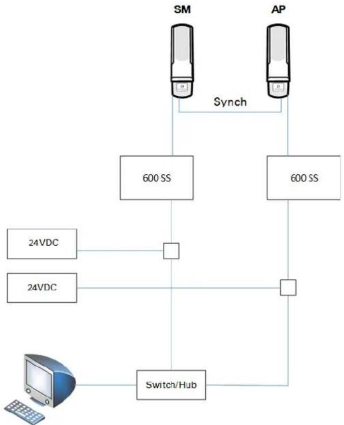
flowchart
graph TD
    A["SM"] -->|Synch| B["AP"]
    B --> C["600 SS"]
    C --> D["Switch/Hub"]
    E["24VDC"] --> D
    F["24VDC"] --> D
    D --> G["Switch/Hub"]
If the SM simply serves as a relay, you must use a straight-through RJ-45 female-to-female coupler and wire the SM to the remote AP as shown in Figure 65.
Figure 65 Remote AP wired to SM that serves as a relay

flowchart
graph TD
    A["SM"] -->|Synch| B["AP"]
    B -->|Data| C["Coupler"]
    C --> D["24VDC"]
    C --> E["24VDC"]
Passing Sync signal
Passing Sync in a Single Hop
Network sync can be passed in a single hop in the following network designs:
- Design 1
○ A CMM provides sync to a co-located AP.
- This AP sends the sync over the air to SMs.
- Design 2
- A CMM provides sync to a co-located BH timing master.
- This BH timing master sends the sync over the air to a BH timing slave.
Passing Sync in an Additional Hop
Network sync can be extended by one additional link in any of the following network designs:

Note
In each of these following designs, Link 2 is not on the same frequency band as Link 4. (For example, Link 2 may be a 5.2 GHz link while Link 4 is a 5.7 or 2.4 GHz link.)
- Design 3
○ A CMM provides sync to a co-located AP.
- This AP sends the sync over the air to an SM.
- This SM delivers the sync to a co-located AP.
- This AP passes the sync in the additional link over the air to SMs.
This design is illustrated in Figure 66.
Figure 66 Additional link to extend network sync, Design 3

flowchart
graph TD
    A["AP"] -->|1| B["CMM"]
    A -->|2| C["SM"]
    C -->|3| D["Remote AP"]
    D -->|4| E["AP"]
    E -->|4| F["SM"]
    F --> G["SM"]
    G --> H["SM"]
- Design 4
○ A CMM provides sync to a co-located AP.
- This AP sends the sync over the air to an SM.
- This SM delivers the sync to a co-located BHM.
- This BHM passes the sync in the additional link over the air to a BHS.
This design is illustrated in Figure 67.
Figure 67 Additional link to extend network sync, Design 4

flowchart
graph LR
    AP["AP"] -->|1| CMM["CMM"]
    AP -->|2| SM["SM"]
    SM -->|3| BHM["BHM"]
    BHM -->|4| BHS["BHS"]
- Design 5
○ A CMM provides sync to a co-located BHM or the BHM generates timing.
- This BHM sends the sync over the air to a BHS.
- This BHS delivers the sync to a co-located AP.
This AP passes the sync in the additional link over the air to SMs.
This design is illustrated in Figure 68.
Figure 68 Additional link to extend network sync, Design 5
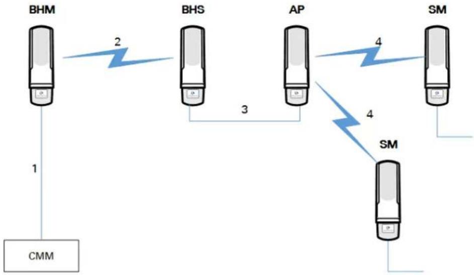
flowchart
graph TD
    A["BHM"] -->|1| B["CMM"]
    B -->|2| C["BHS"]
    C -->|3| D["AP"]
    D -->|4| E["SM"]
    E -->|4| F["SM"]
    F --> G["SM"]
    style A fill:#f9f,stroke:#333
    style B fill:#ccf,stroke:#333
    style C fill:#cfc,stroke:#333
    style D fill:#fcc,stroke:#333
    style E fill:#cff,stroke:#333
    style F fill:#ffc,stroke:#333
    style G fill:#cfc,stroke:#333
Wiring and configuration information for this sync extension is described under Wiring to Extend Network Sync on page 3-60.
Wiring to Extend Network Sync
The following procedure can be used to extend network sync by one additional hop, as described under Passing Sync in an Additional Hop on page 3-57. When a co-located module receives sync over the air, the co-located modules can be wired to pass the sync as follows:
- Connect the GPS Utility ports of the co-located modules using a sync cable with RJ-11 (for 450) or RJ-45 (for 450i/450m) connectors.
- Set the Sync Input parameter on the Configuration page of the co-located AP or BH timing master to AutoSync.
- Set the Device Type parameter on the Configuration page of the co-located AP or BH timing master to Remote.
- Set the Sync Output to Aux Port parameter on the Configuration page of the colocated AP or BH timing master to Disabled.
- Set the UGPS Power parameter on the Configuration page of the co-located AP or BH timing master to Disabled.
- Set the Frame Timing Pulse Gated parameter on the Configuration page of the colocated SM or BH timing slave to Enable.

Note
This setting prevents interference if the SM or BH timing slave loses sync.
Figure 69 Co-located AP or BH timing master Sync Setting configuration
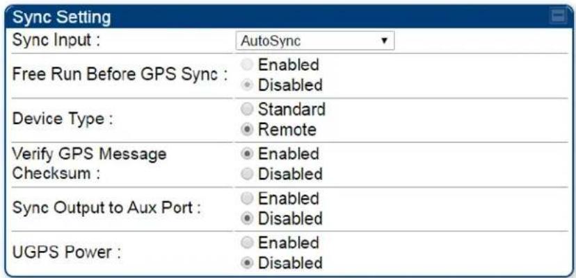
Chapter 4: Legal and regulatory information
This chapter provides end user license agreements and regulatory notifications.

Caution
Intentional or unintentional changes or modifications to the equipment must not be made unless under the express consent of the party responsible for compliance. Any such modifications could void the user's authority to operate the equipment and will void the manufacturer's warranty.

Attention
The following topics are described in this chapter:
- Cambium Networks end user license agreement on page 4-2 contains the Cambium and third-party license agreements for the 450 Platform Family ODUs.
- Compliance with safety standards on page 4-22 lists the safety specifications against which the 450 Platform Family has been tested and certified. It also describes how to keep RF exposure within safe limits.
- Compliance with radio regulations on page 4-39 describes how the 450 Platform Family complies with the radio regulations that are in force in various countries, and contains notifications made to regulatory bodies for the 450 Platform Family.
Cambium Networks end user license agreement
Definitions
In this Agreement, the word “Software” refers to the set of instructions for computers, in executable form and in any media, (which may include diskette, CD-ROM, downloadable internet, hardware, or firmware) licensed to you. The word “Documentation” refers to electronic or printed manuals and accompanying instructional aids licensed to you. The word “Product” refers to Cambium Networks’ fixed wireless broadband devices for which the Software and Documentation is licensed for use.
Acceptance of this agreement
In connection with Cambium Networks' delivery of certain proprietary software or products containing embedded or pre-loaded proprietary software, or both, Cambium Networks is willing to license this certain proprietary software and the accompanying documentation to you only on the condition that you accept all the terms in this End User License Agreement ("Agreement").
IF YOU DO NOT AGREE TO THE TERMS OF THIS AGREEMENT, DO NOT USE THE PRODUCT OR INSTALL THE SOFTWARE. INSTEAD, YOU MAY, FOR A FULL REFUND, RETURN THIS PRODUCT TO THE LOCATION WHERE YOU ACQUIRED IT OR PROVIDE WRITTEN VERIFICATION OF DELETION OF ALL COPIES OF THE SOFTWARE. ANY USE OF THE SOFTWARE, INCLUDING BUT NOT LIMITED TO USE ON THE PRODUCT, WILL CONSTITUTE YOUR ACCEPTANCE TO THE TERMS OF THIS AGREEMENT.
Grant of license
Cambium Networks Limited (“Cambium”) grants you (“Licensee” or “you”) a personal, nonexclusive, non-transferable license to use the Software and Documentation subject to the Conditions of Use set forth in “Conditions of use” and the terms and conditions of this Agreement. Any terms or conditions relating to the Software and Documentation appearing on the face or reverse side of any purchase order, purchase order acknowledgment or other order document that are different from, or in addition to, the terms of this Agreement will not be binding on the parties, even if payment is accepted.
Conditions of use
Any use of the Software and Documentation outside of the conditions set forth in this Agreement is strictly prohibited and will be deemed a breach of this Agreement.
-
Only you, your employees or agents may use the Software and Documentation. You will take all necessary steps to insure that your employees and agents abide by the terms of this Agreement.
-
You will use the Software and Documentation (i) only for your internal business purposes; (ii) only as described in the Software and Documentation; and (iii) in strict accordance with this Agreement.
-
You may use the Software and Documentation, provided that the use is in conformance with the terms set forth in this Agreement.
-
Portions of the Software and Documentation are protected by United States copyright laws, international treaty provisions, and other applicable laws. Therefore, you must treat the Software like any other copyrighted material (for example, a book or musical recording) except that you may either: (i) make 1 copy of the transportable part of the Software (which typically is supplied on diskette, CD-ROM, or downloadable internet), solely for back-up purposes; or (ii) copy the transportable part of the Software to a PC hard disk, provided you keep the original solely for back-up purposes. If the Documentation is in printed form, it may not be copied. If the Documentation is in electronic form, you may print out 1 copy, which then may not be copied. With regard to the copy made for backup or archival purposes, you agree to reproduce any Cambium Networks copyright notice, and other proprietary legends appearing thereon. Such copyright notice(s) may appear in any of several forms, including machine-readable form, and you agree to reproduce such notice in each form in which it appears, to the extent it is physically possible to do so. Unauthorized duplication of the Software or Documentation constitutes copyright infringement, and in the United States is punishable in federal court by fine and imprisonment.
-
You will not transfer, directly or indirectly, any product, technical data or software to any country for which the United States Government requires an export license or other governmental approval without first obtaining such license or approval.
Title and restrictions
If you transfer possession of any copy of the Software and Documentation to another party outside of the terms of this agreement, your license is automatically terminated. Title and copyrights to the Software and Documentation and any copies made by you remain with Cambium Networks and its licensors. You will not, and will not permit others to: (i) modify, translate, decompile, bootleg, reverse engineer, disassemble, or extract the inner workings of the Software or Documentation, (ii) copy the look-and-feel or functionality of the Software or Documentation; (iii) remove any proprietary notices, marks, labels, or logos from the Software or Documentation; (iv) rent or transfer all or some of the Software or Documentation to any other party without Cambium's prior written consent; or (v) utilize any computer software or hardware which is designed to defeat any copy protection device, should the Software and Documentation be equipped with such a protection device. If the Software and Documentation is provided on multiple types of media (such as diskette, CD-ROM, downloadable internet), then you will only use the medium which best meets your specific needs, and will not loan, rent, lease, or transfer the other media contained in the package without Cambium's written consent. Unauthorized copying of the Software or Documentation, or failure to comply with any of the provisions of this Agreement, will result in automatic termination of this license.
Confidentiality
You acknowledge that all Software and Documentation contain valuable proprietary information and trade secrets and that unauthorized or improper use of the Software and Documentation will result in irreparable harm to Cambium Networks for which monetary damages would be inadequate and for which Cambium Networks will be entitled to immediate injunctive relief. If applicable, you will limit access to the Software and Documentation to those of your employees and agents who need to use the Software and Documentation for your internal business purposes, and you will take appropriate action with those employees and agents to preserve the confidentiality of the Software and Documentation, using the same degree of care to avoid unauthorized or improper disclosure as you use for the protection of your own proprietary software, but in no event less than reasonable care.
You have no obligation to preserve the confidentiality of any proprietary information that: (i) was in the public domain at the time of disclosure; (ii) entered the public domain through no fault of yours; (iii) was given to you free of any obligation to keep it confidential; (iv) is independently developed by you; or (v) is disclosed as required by law provided that you notify Cambium Networks prior to such disclosure and provide Cambium Networks with a reasonable opportunity to respond.
Right to use Cambium's name
Except as required in “Conditions of use”, you will not, during the term of this Agreement or thereafter, use any trademark of Cambium Networks, or any word or symbol likely to be confused with any Cambium Networks trademark, either alone or in any combination with another word or words.
Transfer
The Software and Documentation may not be transferred to another party without the express written consent of Cambium Networks, regardless of whether or not such transfer is accomplished by physical or electronic means. Cambium's consent may be withheld at its discretion and may be conditioned upon transferee paying all applicable license fees and agreeing to be bound by this Agreement.
Updates
During the first 12 months after purchase of a Product, or during the term of any executed Maintenance and Support Agreement for the Product, you are entitled to receive Updates. An "Update" means any code in any form which is a bug fix, patch, error correction, or minor enhancement, but excludes any major feature added to the Software. Updates are available for download at the support website.
Major features may be available from time to time for an additional license fee. If Cambium Networks makes available to your major features and no other end user license agreement is provided, then the terms of this Agreement will apply.
Maintenance
Except as provided above, Cambium Networks is not responsible for maintenance or field service of the Software under this Agreement.
Disclaimer
CAMBIUM NETWORKS DISCLAIMS ALL WARRANTIES OF ANY KIND, WHETHER EXPRESS, IMPLIED, STATUTORY, OR IN ANY COMMUNICATION WITH YOU. CAMBIUM NETWORKS SPECIFICALLY DISCLAIMS ANY WARRANTY INCLUDING THE IMPLIED WARRANTIES OF MERCHANTABILITY, NONINFRINGEMENT, OR FITNESS FOR A PARTICULAR PURPOSE. THE SOFTWARE AND DOCUMENTATION ARE PROVIDED "AS IS." CAMBIUM NETWORKS DOES NOT WARRANT THAT THE SOFTWARE WILL MEET YOUR REQUIREMENTS, OR THAT THE OPERATION OF THE SOFTWARE WILL BE UNINTERRUPTED OR ERROR FREE, OR THAT DEFECTS IN THE SOFTWARE WILL BE CORRECTED. CAMBIUM NETWORKS MAKES NO WARRANTY WITH RESPECT TO THE CORRECTNESS, ACCURACY, OR RELIABILITY OF THE SOFTWARE AND DOCUMENTATION. Some jurisdictions do not allow the exclusion of implied warranties, so the above exclusion may not apply to you.
Limitation of liability
IN NO EVENT SHALL CAMBIUM NETWORKS BE LIABLE TO YOU OR ANY OTHER PARTY FOR ANY DIRECT, INDIRECT, GENERAL, SPECIAL, INCIDENTAL, CONSEQUENTIAL, EXEMPLARY OR OTHER DAMAGE ARISING OUT OF THE USE OR INABILITY TO USE THE PRODUCT (INCLUDING, WITHOUT LIMITATION, DAMAGES FOR LOSS OF BUSINESS PROFITS, BUSINESS INTERRUPTION, LOSS OF BUSINESS INFORMATION OR ANY OTHER PECUNIARY LOSS, OR FROM ANY BREACH OF WARRANTY, EVEN IF CAMBIUM NETWORKS HAS BEEN ADVISED OF THE POSSIBILITY OF SUCH DAMAGES. (Some states do not allow the exclusion or limitation of incidental or consequential damages, so the above exclusion or limitation may not apply to you.) IN NO CASE SHALL CAMBIUM'S LIABILITY EXCEED THE AMOUNT YOU PAID FOR THE PRODUCT.
U.S. government
If you are acquiring the Product on behalf of any unit or agency of the U.S. Government, the following applies. Use, duplication, or disclosure of the Software and Documentation is subject to the restrictions set forth in subparagraphs (c) (1) and (2) of the Commercial Computer Software - Restricted Rights clause at FAR 52.227-19 (JUNE 1987), if applicable, unless being provided to the Department of Defense. If being provided to the Department of Defense, use, duplication, or disclosure of the Products is subject to the restricted rights set forth in subparagraph (c) (1) (ii) of the Rights in Technical Data and Computer Software clause at DFARS 252.227-7013 (OCT 1988), if applicable. Software and Documentation may or may not include a Restricted Rights notice, or other notice referring specifically to the terms and conditions of this Agreement. The terms and conditions of this Agreement will each continue to apply, but only to the extent that such terms and conditions are not inconsistent with the rights provided to you under the aforementioned provisions of the FAR and DFARS, as applicable to the particular procuring agency and procurement transaction.
Term of license
Your right to use the Software will continue in perpetuity unless terminated as follows. Your right to use the Software will terminate immediately without notice upon a breach of this Agreement by you. Within 30 days after termination of this Agreement, you will certify to Cambium Networks in writing that through your best efforts, and to the best of your knowledge, the original and all copies, in whole or in part, in any form, of the Software and all related material and Documentation, have been destroyed, except that, with prior written consent from Cambium Networks, you may retain one copy for archival or backup purposes. You may not sublicense, assign or transfer the license or the Product, except as expressly provided in this Agreement. Any attempt to otherwise sublicense, assign or transfer any of the rights, duties or obligations hereunder is null and void.
Governing law
This Agreement is governed by the laws of the United States of America to the extent that they apply and otherwise by the laws of the State of Illinois.
Assignment
This agreement may not be assigned by you without Cambium's prior written consent.
Survival of provisions
The parties agree that where the context of any provision indicates an intent that it survives the term of this Agreement, then it will survive.
Entire agreement
This agreement contains the parties' entire agreement regarding your use of the Software and may be amended only in writing signed by both parties, except that Cambium Networks may modify this Agreement as necessary to comply with applicable laws.
Third party software
The software may contain one or more items of Third-Party Software supplied by other third-party suppliers. The terms of this Agreement govern your use of any Third-Party Software UNLESS A SEPARATE THIRD-PARTY SOFTWARE LICENSE IS INCLUDED, IN WHICH CASE YOUR USE OF THE THIRD-PARTY SOFTWARE WILL THEN BE GOVERNED BY THE SEPARATE THIRD-PARTY LICENSE.
Net SNMP
Various copyrights apply to this package, listed in various separate parts below. Please make sure that you read all the parts.
---- Part 1: CMU/UCD copyright notice: (BSD like) ----
Copyright 1989, 1991, 1992 by Carnegie Mellon University
Derivative Work - 1996, 1998-2000
Copyright 1996, 1998-2000 The Regents of the University of California
All Rights Reserved
Permission to use, copy, modify and distribute this software and its documentation for any purpose and without fee is hereby granted, provided that the above copyright notice appears in all copies and that both that copyright notice and this permission notice appear in supporting documentation, and that the name of CMU and The Regents of the University of California not be used in advertising or publicity pertaining to distribution of the software without specific written permission.
CMU AND THE REGENTS OF THE UNIVERSITY OF CALIFORNIA DISCLAIM ALL WARRANTIES WITH REGARD TO THIS SOFTWARE, INCLUDING ALL IMPLIED WARRANTIES OF MERCHANTABILITY AND FITNESS. IN NO EVENT SHALL CMU OR THE REGENTS OF THE UNIVERSITY OF CALIFORNIA BE LIABLE FOR ANY SPECIAL, INDIRECT OR CONSEQUENTIAL DAMAGES OR ANY DAMAGES WHATSOEVER RESULTING FROM THE LOSS OF USE, DATA OR PROFITS, WHETHER IN AN ACTION OF CONTRACT, NEGLIGENCE OR OTHER TORTIOUS ACTION, ARISING OUT OF OR IN CONNECTION WITH THE USE OR PERFORMANCE OF THIS SOFTWARE.
---- Part 2: Networks Associates Technology, Inc copyright notice (BSD) ----
Copyright © 2001-2003, Networks Associates Technology, Inc
All rights reserved.
Redistribution and use in source and binary forms, with or without modification, are permitted provided that the following conditions are met:
- Redistributions of source code must retain the above copyright notice, this list of conditions and the following disclaimer.
- Redistributions in binary form must reproduce the above copyright notice, this list of conditions and the following disclaimer in the documentation and/or other materials provided with the distribution.
- Neither the name of the Networks Associates Technology, Inc nor the names of its contributors may be used to endorse or promote products derived from this software without specific prior written permission.
THIS SOFTWARE IS PROVIDED BY THE COPYRIGHT HOLDERS AND CONTRIBUTORS "AS IS" AND ANY EXPRESS OR IMPLIED WARRANTIES, INCLUDING, BUT NOT LIMITED TO, THE IMPLIED WARRANTIES OF MERCHANTABILITY AND FITNESS FOR A PARTICULAR PURPOSE ARE DISCLAIMED. IN NO EVENT SHALL THE COPYRIGHT HOLDERS OR CONTRIBUTORS BE LIABLE FOR ANY DIRECT, INDIRECT, INCIDENTAL, SPECIAL, EXEMPLARY, OR CONSEQUENTIAL DAMAGES (INCLUDING, BUT NOT LIMITED TO, PROCUREMENT OF SUBSTITUTE GOODS OR SERVICES; LOSS OF USE, DATA, OR PROFITS; OR BUSINESS INTERRUPTION) HOWEVER CAUSED AND ON ANY THEORY OF LIABILITY, WHETHER IN CONTRACT, STRICT LIABILITY, OR TORT (INCLUDING NEGLIGENCE OR OTHERWISE) ARISING IN ANY WAY OUT OF THE USE OF THIS SOFTWARE, EVEN IF ADVISED OF THE POSSIBILITY OF SUCH DAMAGE.
---- Part 3: Cambridge Broadband Ltd. copyright notice (BSD) ----
Portions of this code are copyright © 2001-2003, Cambridge Broadband Ltd.
All rights reserved.
Redistribution and use in source and binary forms, with or without modification, are permitted provided that the following conditions are met:
- Redistributions of source code must retain the above copyright notice, this list of conditions and the following disclaimer.
- Redistributions in binary form must reproduce the above copyright notice, this list of conditions and the following disclaimer in the documentation and/or other materials provided with the distribution.
- The name of Cambridge Broadband Ltd. may not be used to endorse or promote products derived from this software without specific prior written permission.
THIS SOFTWARE IS PROVIDED BY THE COPYRIGHT HOLDER "AS IS" AND ANY EXPRESS OR IMPLIED WARRANTIES, INCLUDING, BUT NOT LIMITED TO, THE IMPLIED WARRANTIES OF MERCHANTABILITY AND FITNESS FOR A PARTICULAR PURPOSE ARE DISCLAIMED. IN NO EVENT SHALL THE COPYRIGHT HOLDER BE LIABLE FOR ANY DIRECT, INDIRECT, INCIDENTAL, SPECIAL, EXEMPLARY, OR CONSEQUENTIAL DAMAGES (INCLUDING, BUT NOT LIMITED TO, PROCUREMENT OF SUBSTITUTE GOODS OR SERVICES; LOSS OF USE, DATA, OR PROFITS; OR BUSINESS INTERRUPTION) HOWEVER CAUSED AND ON ANY THEORY OF LIABILITY, WHETHER IN CONTRACT, STRICT LIABILITY, OR TORT (INCLUDING NEGLIGENCE OR OTHERWISE) ARISING IN ANY WAY OUT OF THE USE OF THIS SOFTWARE, EVEN IF ADVISED OF THE POSSIBILITY OF SUCH DAMAGE.
---- Part 4: Sun Microsystems, Inc. copyright notice (BSD) ----
Copyright © 2003 Sun Microsystems, Inc., 4150 Network Circle, Santa Clara,
California 95054, U.S.A. All rights reserved.
Use is subject to license terms below.
This distribution may include materials developed by third parties.
Sun, Sun Microsystems, the Sun logo and Solaris are trademarks or registered trademarks of Sun Microsystems, Inc. in the U.S. and other countries.
Redistribution and use in source and binary forms, with or without modification, are permitted provided that the following conditions are met:
- Redistributions of source code must retain the above copyright notice, this list of conditions and the following disclaimer.
- Redistributions in binary form must reproduce the above copyright notice, this list of conditions and the following disclaimer in the documentation and/or other materials provided with the distribution.
- Neither the name of the Sun Microsystems, Inc. nor the names of its contributors may be used to endorse or promote products derived from this software without specific prior written permission.
THIS SOFTWARE IS PROVIDED BY THE COPYRIGHT HOLDERS AND CONTRIBUTORS “AS IS” AND ANY EXPRESS OR IMPLIED WARRANTIES, INCLUDING, BUT NOT LIMITED TO, THE IMPLIED WARRANTIES OF MERCHANTABILITY AND FITNESS FOR A PARTICULAR PURPOSE ARE DISCLAIMED. IN NO EVENT SHALL THE COPYRIGHT HOLDERS OR CONTRIBUTORS BE LIABLE FOR ANY DIRECT, INDIRECT, INCIDENTAL, SPECIAL, EXEMPLARY, OR CONSEQUENTIAL DAMAGES (INCLUDING, BUT NOT LIMITED TO, PROCUREMENT OF SUBSTITUTE GOODS OR SERVICES; LOSS OF USE, DATA, OR PROFITS; OR BUSINESS INTERRUPTION) HOWEVER CAUSED AND ON ANY THEORY OF LIABILITY, WHETHER IN CONTRACT, STRICT LIABILITY, OR TORT (INCLUDING NEGLIGENCE OR OTHERWISE) ARISING IN ANY WAY OUT OF THE USE OF THIS SOFTWARE, EVEN IF ADVISED OF THE POSSIBILITY OF SUCH DAMAGE.
---- Part 5: Sparta, Inc copyright notice (BSD) ----
Copyright © 2003-2008, Sparta, Inc
All rights reserved.
Redistribution and use in source and binary forms, with or without modification, are permitted provided that the following conditions are met:
- Redistributions of source code must retain the above copyright notice, this list of conditions and the following disclaimer.
- Redistributions in binary form must reproduce the above copyright notice, this list of conditions and the following disclaimer in the documentation and/or other materials provided with the distribution.
- Neither the name of Sparta, Inc nor the names of its contributors may be used to endorse or promote products derived from this software without specific prior written permission.
THIS SOFTWARE IS PROVIDED BY THE COPYRIGHT HOLDERS AND CONTRIBUTORS “AS IS” AND ANY EXPRESS OR IMPLIED WARRANTIES, INCLUDING, BUT NOT LIMITED TO, THE IMPLIED WARRANTIES OF MERCHANTABILITY AND FITNESS FOR A PARTICULAR PURPOSE ARE DISCLAIMED. IN NO EVENT SHALL THE COPYRIGHT HOLDERS OR CONTRIBUTORS BE LIABLE FOR ANY DIRECT, INDIRECT, INCIDENTAL, SPECIAL, EXEMPLARY, OR CONSEQUENTIAL DAMAGES (INCLUDING, BUT NOT LIMITED TO, PROCUREMENT OF SUBSTITUTE GOODS OR SERVICES; LOSS OF USE, DATA, OR PROFITS; OR BUSINESS INTERRUPTION) HOWEVER CAUSED AND ON ANY THEORY OF LIABILITY, WHETHER IN CONTRACT, STRICT LIABILITY, OR TORT (INCLUDING NEGLIGENCE OR OTHERWISE) ARISING IN ANY WAY OUT OF THE USE OF THIS SOFTWARE, EVEN IF ADVISED OF THE POSSIBILITY OF SUCH DAMAGE.
---- Part 6: Cisco/BUPTNIC copyright notice (BSD) ----
Copyright © 2004, Cisco, Inc and Information Network
Center of Beijing University of Posts and Telecommunications.
All rights reserved.
Redistribution and use in source and binary forms, with or without modification, are permitted provided that the following conditions are met:
- Redistributions of source code must retain the above copyright notice, this list of conditions and the following disclaimer.
- Redistributions in binary form must reproduce the above copyright notice, this list of conditions and the following disclaimer in the documentation and/or other materials provided with the distribution.
- Neither the name of Cisco, Inc, Beijing University of Posts and Telecommunications, nor the names of their contributors may be used to endorse or promote products derived from this software without specific prior written permission.
THIS SOFTWARE IS PROVIDED BY THE COPYRIGHT HOLDERS AND CONTRIBUTORS "AS IS" AND ANY EXPRESS OR IMPLIED WARRANTIES, INCLUDING, BUT NOT LIMITED TO, THE IMPLIED WARRANTIES OF MERCHANTABILITY AND FITNESS FOR A PARTICULAR PURPOSE ARE DISCLAIMED. IN NO EVENT SHALL THE COPYRIGHT HOLDERS OR CONTRIBUTORS BE LIABLE FOR ANY DIRECT, INDIRECT, INCIDENTAL, SPECIAL, EXEMPLARY, OR CONSEQUENTIAL DAMAGES (INCLUDING, BUT NOT LIMITED TO, PROCUREMENT OF SUBSTITUTE GOODS OR SERVICES; LOSS OF USE, DATA, OR PROFITS; OR BUSINESS INTERRUPTION) HOWEVER CAUSED AND ON ANY THEORY OF LIABILITY, WHETHER IN CONTRACT, STRICT LIABILITY, OR TORT (INCLUDING NEGLIGENCE OR OTHERWISE) ARISING IN ANY WAY OUT OF THE USE OF THIS SOFTWARE, EVEN IF ADVISED OF THE POSSIBILITY OF SUCH DAMAGE.
---- Part 7: Fabasoft R&D Software GmbH & Co KG copyright notice (BSD) ----
Copyright © Fabasoft R&D Software GmbH & Co KG, 2003
oss@fabasoft.com
Author: Bernhard Penz
Redistribution and use in source and binary forms, with or without modification, are permitted provided that the following conditions are met:
- Redistributions of source code must retain the above copyright notice, this list of conditions and the following disclaimer.
- Redistributions in binary form must reproduce the above copyright notice, this list of conditions and the following disclaimer in the documentation and/or other materials provided with the distribution.
- The name of Fabasoft R&D Software GmbH & Co KG or any of its subsidiaries, brand or product names may not be used to endorse or promote products derived from this software without specific prior written permission.
THIS SOFTWARE IS PROVIDED BY THE COPYRIGHT HOLDER "AS IS" AND ANY EXPRESS OR IMPLIED WARRANTIES, INCLUDING, BUT NOT LIMITED TO, THE IMPLIED WARRANTIES OF MERCHANTABILITY AND FITNESS FOR A PARTICULAR PURPOSE ARE DISCLAIMED. IN NO EVENT SHALL THE COPYRIGHT HOLDER BE LIABLE FOR ANY DIRECT, INDIRECT, INCIDENTAL, SPECIAL, EXEMPLARY, OR CONSEQUENTIAL DAMAGES (INCLUDING, BUT NOT LIMITED TO, PROCUREMENT OF SUBSTITUTE GOODS OR SERVICES; LOSS OF USE, DATA, OR PROFITS; OR BUSINESS INTERRUPTION) HOWEVER CAUSED AND ON ANY THEORY OF LIABILITY, WHETHER IN CONTRACT, STRICT LIABILITY, OR TORT (INCLUDING NEGLIGENCE OR OTHERWISE) ARISING IN ANY WAY OUT OF THE USE OF THIS SOFTWARE, EVEN IF ADVISED OF THE POSSIBILITY OF SUCH DAMAGE.
OpenSSL
Copyright (c) 1998-2008 The OpenSSL Project. All rights reserved.
Redistribution and use in source and binary forms, with or without modification, are permitted provided that the following conditions are met:
- Redistributions of source code must retain the above copyright notice, this list of conditions and the following disclaimer.
- Redistributions in binary form must reproduce the above copyright notice, this list of conditions and the following disclaimer in the documentation and/or other materials provided with the distribution.
- All advertising materials mentioning features or use of this software must display the following acknowledgment:
"This product includes software developed by the OpenSSL Project for use in the OpenSSL Toolkit. (http://www.openssl.org/)
- The names "OpenSSL Toolkit" and "OpenSSL Project" must not be used to endorse or promote products derived from this software without prior written permission. For written permission, please contact openssl-core@openssl.org.
- Products derived from this software may not be called "OpenSSL" nor may "OpenSSL" appear in their names without prior written permission of the OpenSSL Project.
- Redistributions of any form whatsoever must retain the following acknowledgment: "This product includes software developed by the OpenSSL Project for use in the OpenSSL Toolkit (http://www.openssl.org/)
THIS SOFTWARE IS PROVIDED BY THE OpenSSL PROJECT "AS IS" AND ANY EXPRESSED OR IMPLIED WARRANTIES, INCLUDING, BUT NOT LIMITED TO, THE IMPLIED WARRANTIES OF MERCHANTABILITY AND FITNESS FOR A PARTICULAR PURPOSE ARE DISCLAIMED. IN NO EVENT SHALL THE OpenSSL PROJECT OR ITS CONTRIBUTORS BE LIABLE FOR ANY DIRECT, INDIRECT, INCIDENTAL, SPECIAL, EXEMPLARY, OR CONSEQUENTIAL DAMAGES (INCLUDING, BUT NOT LIMITED TO, PROCUREMENT OF SUBSTITUTE GOODS OR SERVICES; LOSS OF USE, DATA, OR PROFITS; OR BUSINESS INTERRUPTION) HOWEVER CAUSED AND ON ANY THEORY OF LIABILITY, WHETHER IN CONTRACT, STRICT LIABILITY, OR TORT (INCLUDING NEGLIGENCE OR OTHERWISE) ARISING IN ANY WAY OUT OF THE USE OF THIS SOFTWARE, EVEN IF ADVISED OF THE POSSIBILITY OF SUCH DAMAGE.
This product includes cryptographic software written by Eric Young (eay@cryptsoft.com).
This product includes software written by Tim Hudson (tjh@cryptsoft.com).
Original SSLeay License
Copyright © 1995-1998 Eric Young (eay@cryptsoft.com)
All rights reserved.
This package is an SSL implementation written by Eric Young (eay@cryptsoft.com). The implementation was written so as to conform with Netscapes SSL.
This library is free for commercial and non-commercial use as long as the following conditions are adhered to. The following conditions apply to all code found in this distribution, be it the RC4, RSA, lhash, DES, etc., code; not just the SSL code. The SSL documentation included with this distribution is covered by the same copyright terms except that the holder is Tim Hudson (tjh@cryptsoft.com).
Copyright remains Eric Young's, and as such any Copyright notices in the code are not to be removed.
If this package is used in a product, Eric Young should be given attribution as the author of the parts of the library used. This can be in the form of a textual message at program startup or in documentation (online or textual) provided with the package.
Redistribution and use in source and binary forms, with or without modification, are permitted provided that the following conditions are met:
-
Redistributions of source code must retain the copyright notice, this list of conditions and the following disclaimer.
-
Redistributions in binary form must reproduce the above copyright notice, this list of conditions and the following disclaimer in the documentation and/or other materials provided with the distribution.
-
All advertising materials mentioning features or use of this software must display the following acknowledgement:
"This product includes cryptographic software written by Eric Young (eay@cryptsoft.com)"
The word ‘cryptographic’ can be left out if the routines from the library being used are not cryptographic related.
- If you include any Windows specific code (or a derivative thereof) from the apps directory (application code) you must include an acknowledgement:
"This product includes software written by Tim Hudson (tjh@cryptsoft.com)"
THIS SOFTWARE IS PROVIDED BY ERIC YOUNG "AS IS" AND ANY EXPRESS OR IMPLIED WARRANTIES, INCLUDING, BUT NOT LIMITED TO, THE IMPLIED WARRANTIES OF MERCHANTABILITY AND FITNESS FOR A PARTICULAR PURPOSE ARE DISCLAIMED. IN NO EVENT SHALL THE AUTHOR OR CONTRIBUTORS BE LIABLE FOR ANY DIRECT, INDIRECT, INCIDENTAL, SPECIAL, EXEMPLARY, OR CONSEQUENTIAL DAMAGES (INCLUDING, BUT NOT LIMITED TO, PROCUREMENT OF SUBSTITUTE GOODS OR SERVICES; LOSS OF USE, DATA, OR PROFITS; OR BUSINESS INTERRUPTION) HOWEVER CAUSED AND ON ANY THEORY OF LIABILITY, WHETHER IN CONTRACT, STRICT LIABILITY, OR TORT (INCLUDING NEGLIGENCE OR OTHERWISE) ARISING IN ANY WAY OUT OF THE USE OF THIS SOFTWARE, EVEN IF ADVISED OF THE POSSIBILITY OF SUCH DAMAGE.
The license and distribution terms for any publicly available version or derivative of this code cannot be changed. i.e. this code cannot simply be copied and put under another distribution license [including the GNU Public License.]
Zlib
Copyright © 1995-2005 Jean-loup Gailly and Mark Adler
This software is provided 'as-is', without any express or implied warranty. In no event will the authors be held liable for any damages arising from the use of this software.
Permission is granted to anyone to use this software for any purpose, including commercial applications, and to alter it and redistribute it freely, subject to the following restrictions:
- The origin of this software must not be misrepresented; you must not claim that you wrote the original software. If you use this software in a product, an acknowledgment in the product documentation would be appreciated but is not required.
- Altered source versions must be plainly marked as such, and must not be misrepresented as being the original software.
- This notice may not be removed or altered from any source distribution.
Jean-loup Gailly jloup@gzip.org
Mark Adler madler@alumni.caltech.edu
Libpng
libpng versions 1.2.6, August 15, 2004, through 1.2.35, February 14, 2009, are Copyright © 2004, 2006-2008 Glenn Randers-Pehrson, and are distributed according to the same disclaimer and license as libpng-1.2.5 with the following individual added to the list of Contributing Authors
Cosmin Truta
libpng versions 1.0.7, July 1, 2000, through 1.2.5 - October 3, 2002, are Copyright © 2000-2002 Glenn Randers-Pehrson, and are distributed according to the same disclaimer and license as libpng-1.0.6 with the following individuals added to the list of Contributing Authors
Simon-Pierre Cadieux
Eric S. Raymond
Gilles Vollant
and with the following additions to the disclaimer:
There is no warranty against interference with your enjoyment of the library or against infringement. There is no warranty that our efforts or the library will fulfil any of your particular purposes or needs. This library is provided with all faults, and the entire risk of satisfactory quality, performance, accuracy, and effort is with the user.
libpng versions 0.97, January 1998, through 1.0.6, March 20, 2000, are Copyright © 1998, 1999 Glenn Randers-Pehrson, and are distributed according to the same disclaimer and license as libpng-0.96, with the following individuals added to the list of Contributing Authors:
Tom Lane
Glenn Randers-Pehrson
Willem van Schaik
libpng versions 0.89, June 1996, through 0.96, May 1997, are Copyright © 1996, 1997 Andreas Dilger
Distributed according to the same disclaimer and license as libpng-0.88, with the following individuals added to the list of Contributing Authors:
John Bowler
Kevin Bracey
Sam Bushell
Magnus Holmgren
Greg Roelofs
Tom Tanner
libpng versions 0.5, May 1995, through 0.88, January 1996, are Copyright © 1995, 1996 Guy Eric Schalnat, Group 42, Inc.
For the purposes of this copyright and license, “Contributing Authors” is defined as the following set of individuals:
Andreas Dilger
Dave Martindale
Guy Eric Schalnat
Paul Schmidt
Tim Wegner
The PNG Reference Library is supplied “AS IS”. The Contributing Authors and Group 42, Inc. disclaim all warranties, expressed or implied, including, without limitation, the warranties of merchantability and of fitness for any purpose. The Contributing Authors and Group 42, Inc. assume no liability for direct, indirect, incidental, special, exemplary, or consequential damages, which may result from the use of the PNG Reference Library, even if advised of the possibility of such damage.
Permission is hereby granted to use, copy, modify, and distribute this source code, or portions hereof, for any purpose, without fee, subject to the following restrictions:
- The origin of this source code must not be misrepresented.
- Altered versions must be plainly marked as such and must not be misrepresented as being the original source.
- This Copyright notice may not be removed or altered from any source or altered source distribution.
The Contributing Authors and Group 42, Inc. specifically permit, without fee, and encourage the use of this source code as a component to supporting the PNG file format in commercial products. If you use this source code in a product, acknowledgment is not required but would be appreciated.
A "png_get_copyright" function is available, for convenient use in "about" boxes and the like: printf("%s", png_get_copyright(NULL));
Also, the PNG logo (in PNG format, of course) is supplied in the files "pngbar.png" and "pngbar.jpg (88x31) and "pngnow.png" (98x31).
Libpng is OSI Certified Open Source Software. OSI Certified Open Source is a certification mark of the Open Source Initiative.
Glenn Randers-Pehrson
glennrp at users.sourceforge.net
February 14, 2009
Bzip2
This program, "bzip2", the associated library "libbzip2", and all documentation, are copyright (C) 1996-2007 Julian R Seward. All rights reserved.
Redistribution and use in source and binary forms, with or without modification, are permitted provided that the following conditions are met:
- Redistributions of source code must retain the above copyright notice, this list of conditions and the following disclaimer.
- The origin of this software must not be misrepresented; you must not claim that you wrote the original software. If you use this software in a product, an acknowledgment in the product documentation would be appreciated but is not required.
- Altered source versions must be plainly marked as such, and must not be misrepresented as being the original software.
- The name of the author may not be used to endorse or promote products derived from this software without specific prior written permission.
THIS SOFTWARE IS PROVIDED BY THE AUTHOR "AS IS" AND ANY EXPRESS OR IMPLIED WARRANTIES, INCLUDING, BUT NOT LIMITED TO, THE IMPLIED WARRANTIES OF MERCHANTABILITY AND FITNESS FOR A PARTICULAR PURPOSE ARE DISCLAIMED. IN NO EVENT SHALL THE AUTHOR BE LIABLE FOR ANY DIRECT, INDIRECT, INCIDENTAL, SPECIAL, EXEMPLARY, OR CONSEQUENTIAL DAMAGES (INCLUDING, BUT NOT LIMITED TO, PROCUREMENT OF SUBSTITUTE GOODS OR SERVICES; LOSS OF USE, DATA, OR PROFITS; OR BUSINESS INTERRUPTION) HOWEVER CAUSED AND ON ANY THEORY OF LIABILITY, WHETHER IN CONTRACT, STRICT LIABILITY, OR TORT (INCLUDING NEGLIGENCE OR OTHERWISE) ARISING IN ANY WAY OUT OF THE USE OF THIS SOFTWARE, EVEN IF ADVISED OF THE POSSIBILITY OF SUCH DAMAGE.
Julian Seward, jseward@bzip.org
USB library functions
Atmel Corporation
2325 Orchard Parkway
San Jose, Ca 95131
Copyright (c) 2004 Atmel
Apache
Apache License
Version 2.0, January 2004
http://www.apache.org/licenses/
TERMS AND CONDITIONS FOR USE, REPRODUCTION, AND DISTRIBUTION
- Definitions.
"License" shall mean the terms and conditions for use, reproduction, and distribution as defined by Sections 1 through 9 of this document.
"Licensor" shall mean the copyright owner or entity authorized by the copyright owner that is granting the License.
"Legal Entity" shall mean the union of the acting entity and all other entities that control, are controlled by, or are under common control with that entity. For the purposes of this definition, "control" means (i) the power, direct or indirect, to cause the direction or management of such entity, whether by contract or otherwise, or (ii) ownership of fifty percent (50%) or more of the outstanding shares, or (iii) beneficial ownership of such entity.
"You" (or "Your") shall mean an individual or Legal Entity exercising permissions granted by this License.
"Source" form shall mean the preferred form for making modifications, including but not limited to software source code, documentation source, and configuration files.
"Object" form shall mean any form resulting from mechanical transformation or translation of a Source form, including but not limited to compiled object code, generated documentation, and conversions to other media types.
"Work" shall mean the work of authorship, whether in Source or Object form, made available under the License, as indicated by a copyright notice that is included in or attached to the work (an example is provided in the Appendix below).
"Derivative Works" shall mean any work, whether in Source or Object form, that is based on (or derived from) the Work and for which the editorial revisions, annotations, elaborations, or other modifications represent, as a whole, an original work of authorship. For the purposes of this License, Derivative Works shall not include works that remain separable from, or merely link (or bind by name) to the interfaces of, the Work and Derivative Works thereof.
"Contribution" shall mean any work of authorship, including the original version of the Work and any modifications or additions to that Work or Derivative Works thereof, that is intentionally submitted to Licensor for inclusion in the Work by the copyright owner or by an individual or Legal Entity authorized to submit on behalf of the copyright owner. For the purposes of this definition, "submitted"
means any form of electronic, verbal, or written communication sent to the Licensor or its representatives, including but not limited to communication on electronic mailing lists, source code control systems, and issue tracking systems that are managed by, or on behalf of, the Licensor for the purpose of discussing and improving the Work, but excluding communication that is conspicuously marked or otherwise designated in writing by the copyright owner as "Not a Contribution."
"Contributor" shall mean Licensor and any individual or Legal Entity on behalf of whom a Contribution has been received by Licensor and subsequently incorporated within the Work.
-
Grant of Copyright License. Subject to the terms and conditions of this License, each Contributor hereby grants to You a perpetual, worldwide, non-exclusive, no-charge, royalty-free, irrevocable copyright license to reproduce, prepare Derivative Works of, publicly display, publicly perform, sublicense, and distribute the Work and such Derivative Works in Source or Object form.
-
Grant of Patent License. Subject to the terms and conditions of this License, each Contributor hereby grants to You a perpetual, worldwide, non-exclusive, no-charge, royalty-free, irrevocable (except as stated in this section) patent license to make, have made, use, offer to sell, sell, import, and otherwise transfer the Work, where such license applies only to those patent claims licensable by such Contributor that are necessarily infringed by their Contribution(s) alone or by combination of their Contribution(s) with the Work to which such Contribution(s) was submitted. If You institute patent litigation against any entity (including a cross-claim or counterclaim in a lawsuit) alleging that the Work or a Contribution incorporated within the Work constitutes direct or contributory patent infringement, then any patent licenses granted to You under this License for that Work shall terminate as of the date such litigation is filed.
-
Redistribution. You may reproduce and distribute copies of the Work or Derivative Works thereof in any medium, with or without modifications, and in Source or Object form, provided that You meet the following conditions:
(a) You must give any other recipients of the Work or Derivative Works a copy of this License; and
(b) You must cause any modified files to carry prominent notices stating that You changed the files; and
(c) You must retain, in the Source form of any Derivative Works that You distribute, all copyright, patent, trademark, and attribution notices from the Source form of the Work, excluding those notices that do not pertain to any part of the Derivative Works; and
(d) If the Work includes a "NOTICE" text file as part of its distribution, then any Derivative Works that You distribute must include a readable copy of the attribution notices contained within such NOTICE file, excluding those notices that do not pertain to any part of the Derivative Works, in at least one
of the following places: within a NOTICE text file distributed as part of the Derivative Works; within the Source form or documentation, if provided along with the Derivative Works; or, within a display generated by the Derivative Works, if and wherever such third-party notices normally appear. The contents of the NOTICE file are for informational purposes only and do not modify the License. You may add Your own attribution notices within Derivative Works that You distribute, alongside or as an addendum to the NOTICE text from the Work, provided that such additional attribution notices cannot be construed as modifying the License.
You may add Your own copyright statement to Your modifications and may provide additional or different license terms and conditions for use, reproduction, or distribution of Your modifications, or for any such Derivative Works as a whole, provided Your use, reproduction, and distribution of the Work otherwise complies with the conditions stated in this License.
-
Submission of Contributions. Unless You explicitly state otherwise, any Contribution intentionally submitted for inclusion in the Work by You to the Licensor shall be under the terms and conditions of this License, without any additional terms or conditions. Notwithstanding the above, nothing herein shall supersede or modify the terms of any separate license agreement you may have executed with Licensor regarding such Contributions.
-
Trademarks. This License does not grant permission to use the trade names, trademarks, service marks, or product names of the Licensor, except as required for reasonable and customary use in describing the origin of the Work and reproducing the content of the NOTICE file.
-
Disclaimer of Warranty. Unless required by applicable law or agreed to in writing, Licensor provides the Work (and each Contributor provides its Contributions) on an "AS IS" BASIS, WITHOUT WARRANTIES OR CONDITIONS OF ANY KIND, either express or implied, including, without limitation, any warranties or conditions of TITLE, NON-INFRINGEMENT, MERCHANTABILITY, or FITNESS FOR A PARTICULAR PURPOSE. You are solely responsible for determining the appropriateness of using or redistributing the Work and assume any risks associated with Your exercise of permissions under this License.
-
Limitation of Liability. In no event and under no legal theory, whether in tort (including negligence), contract, or otherwise, unless required by applicable law (such as deliberate and grossly negligent acts) or agreed to in writing, shall any Contributor be liable to You for damages, including any direct, indirect, special, incidental, or consequential damages of any character arising as a result of this License or out of the use or inability to use the Work (including but not limited to damages for loss of goodwill, work stoppage, computer failure or malfunction, or any and all other commercial damages or losses), even if such Contributor has been advised of the possibility of such damages.
-
Accepting Warranty or Additional Liability. While redistributing the Work or Derivative Works thereof, You may choose to offer, and charge a fee for, acceptance of support, warranty, indemnity,
or other liability obligations and/or rights consistent with this License. However, in accepting such obligations, You may act only on Your own behalf and on Your sole responsibility, not on behalf of any other Contributor, and only if You agree to indemnify, defend, and hold each Contributor harmless for any liability incurred by, or claims asserted against, such Contributor by reason of your accepting any such warranty or additional liability.
END OF TERMS AND CONDITIONS
APPENDIX: How to apply the Apache License to your work.
To apply the Apache License to your work, attach the following boilerplate notice, with the fields enclosed by brackets "[]" replaced with your own identifying information. (Don't include the brackets!) The text should be enclosed in the appropriate comment syntax for the file format. We also recommend that a file or class name and description of purpose be included on the same "printed page" as the copyright notice for easier identification within third-party archives.
Copyright [yyyy] [name of copyright owner]
Licensed under the Apache License, Version 2.0 (the "License"); you may not use this file except in compliance with the License. You may obtain a copy of the License at
http://www.apache.org/licenses/LICENSE-2.0
Unless required by applicable law or agreed to in writing, software distributed under the License is distributed on an "AS IS" BASIS, WITHOUT WARRANTIES OR CONDITIONS OF ANY KIND, either express or implied. See the License for the specific language governing permissions and limitations under the License.
D3 JS library
Copyright (c) 2013, Michael Bostock All rights reserved.
Redistribution and use in source and binary forms, with or without modification, are permitted provided that the following conditions are met:
* Redistributions of source code must retain the above copyright notice, this list of conditions and the following disclaimer.
* Redistributions in binary form must reproduce the above copyright notice, this list of conditions and the following disclaimer in the documentation and/or other materials provided with the distribution.
* The name Michael Bostock may not be used to endorse or promote products derived from this software without specific prior written permission.
THIS SOFTWARE IS PROVIDED BY THE COPYRIGHT HOLDERS AND CONTRIBUTORS "AS IS"
AND ANY EXPRESS OR IMPLIED WARRANTIES, INCLUDING, BUT NOT LIMITED TO, THE IMPLIED WARRANTIES OF MERCHANTABILITY AND FITNESS FOR A PARTICULAR PURPOSE ARE
DISCLAIMED. IN NO EVENT SHALL MICHAEL BOSTOCK BE LIABLE FOR ANY DIRECT, INDIRECT, INCIDENTAL, SPECIAL, EXEMPLARY, OR CONSEQUENTIAL DAMAGES (INCLUDING,
BUT NOT LIMITED TO, PROCUREMENT OF SUBSTITUTE GOODS OR SERVICES; LOSS OF USE,
DATA, OR PROFITS; OR BUSINESS INTERRUPTION) HOWEVER CAUSED AND ON ANY THEORY
OF LIABILITY, WHETHER IN CONTRACT, STRICT LIABILITY, OR TORT (INCLUDING NEGLIGENCE OR OTHERWISE) ARISING IN ANY WAY OUT OF THE USE OF THIS SOFTWARE,
EVEN IF ADVISED OF THE POSSIBILITY OF SUCH DAMAGE.
Compliance with safety standards
This section lists the safety specifications against which the 450 Platform Family has been tested and certified. It also describes how to keep RF exposure within safe limits.
Electrical safety compliance
The 450 Platform Family hardware has been tested for compliance to the electrical safety specifications listed in Table 94.
Table 94 Safety compliance specifications
| Region | Specification |
| USA UL 60950 | |
| Canada CSA C22.2 No.60950 | |
| International CB certified & certificate to IEC 60950 | |
Electromagnetic compatibility (EMC) compliance
The EMC specification type approvals that have been granted for 450 Platform Family are listed under Table 95.
Table 95 EMC emissions compliance
| Region | Specification |
| USA FCC Part 15 Class B | |
| Canada | RSS Gen; RSS-247, RSS-192, and RSS-197 |
| International | EN 301 489-1 V2.1.1EN 301 489-17 V3.1.1EN 301 489-4 V3.1.1 |
Human exposure to radio frequency energy
Relevant standards (USA and EC) applicable when working with RF equipment are:
- ANSI IEEE C95.1-2005, IEEE Standard for Safety Levels with Respect to Human Exposure to Radio Frequency Electromagnetic Fields, 3 kHz to 300 GHz.
- Council recommendation of 12 July 1999 on the limitation of exposure of the general public to electromagnetic fields (0 Hz to 300 GHz) (1999/519/EC) and respective national regulations.
- Directive 2013/35/EU - electromagnetic fields of 26 June 2013 on the minimum health and safety requirements regarding the exposure of workers to the risks arising from physical agents (electromagnetic fields) (20th individual Directive within the meaning of Article 16(1) of Directive 89/391/EEC) and repealing Directive 2004/40/EC.
.
- US FCC limits for the general population. See the FCC web site at http://www.fcc.gov, and the policies, guidelines, and requirements in Part 1 of Title 47 of the Code of Federal Regulations, as well as the guidelines and suggestions for evaluating compliance in FCC OET Bulletin 65.
- Health Canada limits for the general population. See the Health Canada web site at https://www.canada.ca/en/health-canada/services/environmental-workplace-health/consultations/limits-human-exposure-radiofrequency-electromagnetic-energy-frequency-range-3-300.html and Safety Code 6.
- EN 50383: 2010 Basic standard for the calculation and measurement of electromagnetic field strength and SAR related to human exposure from radio base stations and fixed terminal stations for wireless telecommunication systems (110 MHz - 40 GHz).
- BS EN 50385:2017 Product standard to demonstrate the compliances of radio base stations and fixed terminal stations for wireless telecommunication systems with the basic restrictions or the reference levels related to human exposure to radio frequency electromagnetic fields (110 MHz - 40 GHz) - general public.
- ICNIRP (International Commission on Non-Ionizing Radiation Protection) guidelines for the general public. See the ICNIRP web site at https://www.icnirp.org/cms/upload/publications/ICNIRPemfgdl.pdf and Guidelines for Limiting Exposure to Time-Varying Electric, Magnetic, and Electromagnetic Fields.
Power density exposure limit
Install the radios for the 450 Platform Family of wireless solutions so as to provide and maintain the minimum separation distances from all persons.
The applicable FCC power density exposure limit for RF energy in the 3, 4.9, 5.4 and 5.8 GHz frequency bands is 10 W/m^2 and in 900 MHz frequency band is 6 W/m^2 . For more information, see Human exposure to radio frequency energy on page 4-23.
The applicable ISEDC power density exposure limit for RF energy in unlicensed bands is 0.02619 * (f^(0.6834)), where f is the lowest frequency of the supported band. For licensed bands, the power density exposure limit is 0.6455 * (f^(0.5)), where f is the lowest frequency of the supported band.
Calculation of power density
The following calculation is based on the ANSI IEEE C95.1-1991 method, as that provides a worst case analysis. Details of the assessment to EN50383:2002 can be provided, if required. Peak power density in the far field of a radio frequency point source is calculated as follows:
$$ S = \frac {P . G}{4 \pi d ^ {2}} $$
Where: Is:
S power density in W/m
2
P maximum average transmit power
capability of the radio, in W
G total Tx gain as a factor, converted
from dB
d distance from point source, in m
Rearranging terms to solve for distance yields:
$$ d = \sqrt {\frac {P G}{4 \pi S}} $$
Calculated distances and power compliance margins
The following tables show calculated minimum separation distances, recommended distances and resulting margins for each frequency band and antenna combination for the USA and Canada. These are conservative distances that include compliance margins. At these and greater separation distances, the power density from the RF field is below generally accepted limits for the general population.
450 Platform Family ODU adheres to all applicable EIRP limits for transmit power when operating in MIMO mode. Separation distances and compliance margins include compensation for both transmitters.
Explanation of terms used in the following tables:
P burst – maximum average transmit power during transmit burst (Watt)
P - maximum average transmit power of the radio (Watt)
G - total transmit gain as a factor, converted from dB
S - power density (Watt/m2)
d - minimum safe separation distance from point source (meters)
Table 96 FCC minimum safe distances - PMP 450m 3 GHz and 5 GHz (5.1 GHz, 5.2 GHz, 5.4 GHz and 5.8 GHz)
| Band (GHz) | Antenna | PG (W) | S (W/ m2) | d (m) |
| 3.65 | 90° sector | 33.9 | 10 | 0.52 |
| 5.1 | 90° sector | 3.38 | 10 | 0.16 |
| 5.2 | 90° sector | 0.85 | 10 | 0.08 |
| 5.4 | 90° sector | 0.85 | 10 | 0.08 |
| 5.8 | 90° sector | 3.38 | 10 | 0.16 |
Table 97 FCC minimum safe distances - PMP/PTP 450b 4.9 GHz, 5.1 GHz, 5.2 GHz, 5.4 GHz and 5.8 GHz
| Band (GHz) | Antenna | P (W) | G (dBi) | S (W/ m2) | d (m) |
| 4.9 | Dish | 0.501 | 24 | 10 | 1.00 |
| Patch Array | 0.501 | 17 | 10 | 0.45 | |
| On-board | 0.501 | 0 | 10 | 0.06 | |
| 5.1 | Dish | 0.501 | 24 | 10 | 1.00 |
| Patch Array | 0.501 | 17 | 10 | 0.45 | |
| On-board | 0.501 | 0 | 10 | 0.06 | |
| 5.2 | Dish | 0.004 | 24 | 10 | 0.09 |
| Patch Array | 0.020 | 17 | 10 | 0.09 | |
| On-board | 0.251 | 0 | 10 | 0.04 | |
| 5.4 | Dish | 0.004 | 24 | 10 | 0.09 |
| Patch Array | 0.020 | 17 | 10 | 0.09 | |
| On-board | 0.501 | 0 | 10 | 0.06 | |
| 5.8 | Dish | 0.501 | 24 | 10 | 1.00 |
| Patch Array | 0.501 | 17 | 10 | 0.45 | |
| On-board | 0.501 | 0 | 10 | 0.06 |
Table 98 ISED minimum safe distances - PMP 450m 3GHz and 5 GHz (5.4 GHz and 5.8 GHz)
| Band (GHz) | Antenna | PG (W) | S (W/ m2) | d (m) |
| 3.45 | 90° sector | 851 | 6.85 | 3.14 |
| 3.65 | 90° sector | 33.84 | 7.12 | 0.61 |
| 5.4 | 90° sector | 0.85 | 9.39 | 0.08 |
| 5.8 | 90° sector | 3.38 | 9.83 | 0.17 |
Table 99 ISEDC minimum safe distances - PMP/PTP 450b 4.9 GHz, 5.1 GHz, 5.2 GHz, 5.4 GHz and 5.8 GHz
| Band (GHz) | Antenna | P (W) | G (dBi) | S (W/ m2) | d (m) | S @ 20 cm (W/ m2) |
| 4.9 | Dish | 0.501 | 24 | 8.76 | 1.07 | 250.5 |
| Patch Array 0.501 | 17 | 8.76 | 0.48 | 50.0 | ||
| On-board 0.501 | 0 | 8.76 | 0.07 | 1.0 | ||
| 5.1 | Dish | 0.501 | 24 | 9.01 | 1.05 | 250.5 |
| Patch Array 0.501 | 17 | 9.01 | 0.47 | 50.0 | ||
| On-board 0.501 | 0 | 9.01 | 0.07 | 1.0 | ||
| 5.2 | Dish | 0.004 | 24 | 9.13 | 0.09 | 2.0 |
| Patch Array | 0.020 17 | 9.13 0.09 2.0 | ||||
| On-board | 0.251 0 | 9.13 | 0.05 | 0.5 | ||
| 5.4 | Dish | 0.004 | 24 | 9.39 | 0.09 | 2.0 |
| Patch Array | 0.020 17 | 9.39 0.09 2.0 | ||||
| On-board 0.501 | 0 | 9.39 | 0.07 | 1.0 | ||
| 5.8 | Dish | 0.501 | 24 | 9.69 | 1.02 | 250.5 |
| Patch Array 0.501 | 17 | 9.69 | 0.45 | 50.0 | ||
| On-board 0.501 | 0 | 9.69 | 0.06 | 1.0 | ||
Table 100 FCC minimum safe distances - PMP/PTP 450i 900 MHz, 3.65 GHz, 4.9 GHz, 5.1 GHz, 5.2 GHz, 5.4 GHz and 5.8 GHz
| Band | Antenna | P burst (W) | P (W) | G (dBi) | S (W/ m2) | d (m) |
| 900 MHz | Sector antenna | - 0.19 | 22.75 (13 dBi) | 6.0 0.27 | ||
| 3.65 GHz | 90° sector antenna, integrated | - 0.316 | 50.0 (17 dBi) | 10.0 0.36 | ||
| 90° sector antenna, connectorized | - 0.316 | 40.0 (16 dBi) | 10.0 0.32 | |||
| Panel, integrated | - | 0.251 | 79.0 (19 dBi) | 10.0 | 0.40 | |
| 4.9 GHz | Omni-directional | 0.2138 | 0.2512 | 20.0 (13 dBi) | 10.0 | 0.17 |
| 90° sector antenna | 0.2138 | 0.2512 | 50.0 (17 dBi) | 10.0 | 0.26 | |
| 2ft directional flat plate | 0.2138 | 0.2512 | 631.0 (28 dBi) | 10.0 | 0.93 | |
| 4ft directional parabolic | 0.851 | 0.1000 | 2344.0 (34.9 dBi) | 10.0 | 1.14 | |
| 6ft directional parabolic | 0.1413 | 0.1659 | 5248.0 (37.2 dBi) | 10.0 | 2.19 | |
| 5.1 GHz | Omni-directional | 0.170 | 0.200 | 20.0 (13.0 dBi) | 10 | 0.15 |
| 90° sector | 0.034 | 0.040 | 50.1 (17.0 dBi) | 10 | 0.10 | |
| 2ft directional flat plate | 0.002 | 0.002 | 707.9 (28.5 dBi) | 10 | 0.09 | |
| 4ft directional parabolic | 0.011 | 0.013 | 2818.4 (34.5 dBi) | 10 | 0.44 | |
| 5.2 GHz | Omni-directional | 0.036 | 0.042 | 20.0 (13.0 dBi) | 10 | 0.07 |
| 90° sector | 0.014 | 0.017 | 50.1 (17.0 dBi) | 10 | 0.07 | |
| 2ft directional flat plate | 0.001 | 0.001 | 707.9 (28.5 dBi) | 10 | 0.07 | |
| 4ft directional parabolic | 0.000 | 0.000 | 2818.4 (34.5 dBi) | 10 | 0.06 | |
| 5.4 GHz | Omni-directional | 0.036 | 0.042 | 20.0 (13.0 dBi) | 10 | 0.07 |
| 90° sector | 0.014 | 0.017 | 50.1 (17.0 dBi) | 10 | 0.07 | |
| 2ft directional flat plate | 0.001 | 0.017 | 707.9 (28.5 dBi) | 10 | 0.07 | |
| 2ft directional parabolic | 0.001 | 0.001 | 707.9 (28.5 dBi) | 10 | 0.08 | |
| 5.8 GHz | Omni-directional | 0.24 | 0.28 | 20.0 (13 dBi) | 10.0 | 0.18 |
| 90° sector | 0.10 | 0.12 | 50.0 (17 dBi) | 10.0 | 0.18 | |
| 2ft directional flat plate | 0.54 | 0.63 | 708.0 (28.5 dBi) | 10.0 | 1.57 | |
| 4ft directional parabolic | 0.54 | 0.63 | 3388.0 (35.3 dBi) | 10.0 | 3.43 | |
| 6ft directional parabolic | 0.54 | 0.63 | 6457.0 (38.1 dBi) | 10.0 | 4.74 |
Table 101 ISEDC minimum safe distances - PMP/PTP 450i, 900 MHz, 3.5 GHz, 3.65 GHz, 4.9 GHz, 5.2 GHz, 5.4 GHz, and 5.8 GHz
| Band | Antenna | P burst (W) | P (W) | G (dBi) | S (W/ m2) | d (m) |
| 900 MHz | Sector | - | .02 | 20.0 (13 dBi) | 2.74 | 0.11 |
| 3.5 GHz | 90° sector antenna, integrated | - | 0.794 | 50.0 (17 dBi) | 6.99 | 0.62 |
| 90° sector antenna, connectorized | - 0.794 | 40.0 (16 dBi) | 6.99 | 0.55 | ||
| Panel, integrated | - | 0.794 | 79.0 (19 dBi) | 6.99 | 0.78 | |
| 3.65 GHz (Lower Canada) | 90° sector antenna, integrated | - 0.794 | 50.0 (17 dBi) | 7.13 | 0.67 | |
| 90° sector antenna, connectorized | - 0.794 | 40.0 (16 dBi) | 7.13 | 0.59 | ||
| Panel, integrated | - | 0.794 | 79.0 (19 dBi) | 7.13 | 0.84 | |
| 3.65 GHz (Upper Canada) | 90° sector antenna, integrated | - | 0.316 | 50.0 (17 dBi) | 7.13 | 0.42 |
| 90° sector antenna, connectorized | - | 0.316 | 40.0 (16 dBi) | 7.13 | 0.37 | |
| Panel, integrated | - | 0.251 | 79.0 (19 dBi) | 7.13 | 0.47 | |
| 4.9 GHz | Omni-directional | 0.214 | 0.251 | 20.0 (13 dBi) | 8.71 | 0.20 |
| 90° sector | 0.214 | 0.251 | 50.1 (17 dBi) | 8.71 | 0.31 | |
| 2ft directional flat plate | 0.214 | 0.251 | 631.0 (28 dBi) | 8.71 | 1.11 | |
| 6ft directional parabolic | 0.141 | 0.166 | 5248.0 (37.2 dBi) | 8.71 | 2.60 | |
| 5.2 GHz | Omni-directional | 0.009 | 0.011 | 20.0 (13.0 dBi) | 9.13 | 0.04 |
| 90° sector | 0.012 | 0.014 | 50.1 (17.0 dBi) | 9.13 | 0.06 | |
| 2ft directional flat plate | 0.001 | 0.001 | 707.9 (28.5 dBi) | 9.13 | 0.07 | |
| 2ft directional parabolic | 0.001 | 0.001 | 707.9 (28.5 dBi) | 9.13 | 0.06 | |
| 5.4 GHz | Omni-directional | 0.036 | 0.042 | 20.0 (13.0 dBi) | 9.39 | 0.07 |
| 90° sector | 0.014 | 0.017 | 50.1 (17.0 dBi) | 9.39 | 0.07 | |
| 2ft directional flat plate | 0.001 | 0.001 | 707.9 (28.5 dBi) | 9.39 | 0.07 | |
| 2ft directional parabolic | 0.001 | 0.001 | 707.9 (28.5 dBi) | 9.39 | 0.06 | |
| 5.8 GHz | Omni-directional | 0.24 | 0.28 | 20.0 (13 dBi) | 9.69 | 0.20 |
| 90° sector | 0.10 | 0.12 | 50.1 (17 dBi) | 9.69 | 0.20 | |
| 2ft directional flat plate | 0.54 | 0.63 | 707.9 (28.5 dBi) | 9.69 | 1.67 | |
| 4ft directional parabolic | 0.54 | 0.63 | 3388.4 (35.3 dBi) | 9.69 | 4.82 |
Table 102 FCC minimum safe distances - PMP/PTP 450 900 MHz, 2.4 GHz, 3.65 GHz and 5 GHz
| Band | Antenna | P burst (W) | G (dBi) | S (W/ m2) | d (m) |
| 900 MHz | Yagi | 0.032 | 13 (11 dBi) | 6 | 0.07 |
| 2.4 GHz | Sector Antenna | 0.079 | 50 (17 dBi) | 10 | 0.18 |
| Integrated | 0.158 | 6 (8 dBi) | 10 | 0.09 | |
| Reflector 0.040 | 100 (20 dBi) | 10 0.18 | |||
| 3.65 GHz | Sector Antenna 0.316 | 32 (15 dBi) | 10 0.28 | ||
| Integrated 0.316 6 (8 dBi) | 10 0.12 | ||||
| Reflector 0.25 | 100 (20 dBi) | 10 0.45 | |||
| High Gain Ruggedized | 0.25 | 79 (19 dBi) | 10 0.40 | ||
| 5.4 GHz | Sector | 0.025 | 40 (16 dBi) | 10 | 0.09 |
| Integrated | 0.126 | 8 (9 dBi) | 10 | 0.09 | |
| Reflector | 0.003 | 316 (25 dBi) | 10 | 0.09 | |
| CLIP | 0.020 | 50 (17 dBi) | 10 | 0.09 | |
| LENS | 0.032 | 28 (14.5 dBi) | 10 | 0.08 | |
| Integrated Dish (450d) | 0.0032 | 316 (25 dBi) | 10 | 0.09 | |
| 5.8 GHz | Sector | 0.079 | 40 (16 dBi) | 10 | 0.16 |
| Integrated | 0.158 | 8 (9 dBi) | 10 | 0.10 | |
| Reflector | 0.158 | 316 (25 dBi) | 10 | 0.63 | |
| CLIP | 0.158 | 50 (17 dBi) | 10 | 0.25 | |
| LENS | 0.158 | 28 (14.5 dBi) | 10 | 0.19 | |
| Integrated Dish (450d) | 0.158 | 316 (25 dBi) | 10 | 0.63 | |
Table 103 ISEDC minimum safe distances - PMP/PTP 450 900 MHz, 2.4 GHz, 3.5/3.65 GHz and 5 GHz
| Band | Antenna | P burst (W) | G (dBi) | S (W/ m2) | d (m) |
| 900 MHz | Yagi | 0.316 | 13 (11 dBi) | 2.74 | 0.35 |
| 2.4 GHz | Sector Antenna | 0.079 | 50 (17 dBi) | 5.35 | 0.24 |
| Integrated | 0.158 | 6 (8 dBi) | 5.35 | 0.12 | |
| Reflector | 0.040 | 100 (20 dBi) | 5.35 | 0.24 | |
| 3.5 GHz | Sector | 0.316 | 32 (15 dBi) | 37.10 | 0.15 |
| Integrated | 0.316 | 6 (8 dBi) | 37.10 | 0.06 | |
| Reflector 0.316 | 100 (20 dBi) | 37.10 | 0.26 | ||
| High Gain Ruggedized | 0.316 | 79 (19 dBi) | 37.10 | 0.23 | |
| 3.65 GHz (lower Canada) | Sector | 0.316 | 32 (15 dBi) | 38.20 | 0.15 |
| Integrated | 0.316 | 6 (8 dBi) | 38.20 | 0.06 | |
| Reflector 0.316 | 100 (20 dBi) | 38.20 | 0.26 | ||
| High Gain Ruggedized | 0.316 | 79 (19 dBi) | 38.20 | 0.23 | |
| 3.65 GHz (upper Canada) | Sector | 0.316 | 32 (15 dBi) | 38.20 | 0.14 |
| Integrated | 0.316 | 6 (8 dBi) | 38.20 | 0.06 | |
| Reflector 0.20 | 100 (20 dBi) | 38.20 | 0.20 | ||
| High Gain Ruggedized | 0.003 | 79 (19 dBi) | 38.20 | 0.23 | |
| 5.4 GHz | Sector | 0.025 | 40 (16 dBi) | 9.39 | 0.09 |
| Integrated | 0.126 | 8 (9 dBi) | 9.39 | 0.09 | |
| Reflector | 0.003 | 316 (25 dBi) | 9.39 | 0.09 | |
| CLIP | 0.020 | 50 (17 dBi) | 9.39 | 0.09 | |
| LENS | 0.032 | 28 (14.5 dBi) | 9.39 | 0.09 | |
| Integrated Dish (450d) | 0.0032 | 316 (25 dBi) | 9.39 | 0.09 | |
| 5.8 GHz | Sector | .079 | 40 (16 dBi) | 9.69 | 0.16 |
| Integrated | 0.158 | 8 (9 dBi) | 9.69 | 0.10 | |
| Reflector | 0.158 | 316 (25 dBi) | 9.69 | 0.064 | |
| CLIP | 0.158 | 50 (17 dBi) | 9.69 | 0.25 | |
| LENS | 0.158 | 28 (14.5 dBi) | 9.69 | 0.19 | |
| Integrated Dish (450d) | 0.158 | 316 (25 dBi) | 9.69 | 0.64 |
Gain of antenna in dBi = 10 * log(G).
The regulations require that the power used for the calculations is the maximum power in the transmit burst subject to allowance for source-based time-averaging. At 5.4 GHz and EU 5.8 GHz, the products are generally limited to a fixed EIRP which can be achieved with the Integrated Antenna. The calculations above assume that the maximum EIRP allowed by the regulations is being transmitted.

Remarque
Gain de l'antenne en dBi = 10 * log(G).
If there are no EIRP limits in the country of deployment, use the distance calculations for FCC 5.8 GHz for all frequency bands.
At FCC 5.8 GHz, for antennas between 0.6m (2ft) and 1.8m (6ft), alter the distance proportionally to the antenna gain.

Remarque
Hazardous location compliance
The PMP/PTP 450i series ATEX/HAZLOC ODUs have been certified for operation in the following hazardous locations:
ATEX
The products have been approved under an “Intrinsic Safety” assessment as defined in EN60079-11:2007.
The approval is given by certificate number TRAC09ATEX31224X, issued by TRaC Global, with the specific level of coverage shown below:
• II 3 G Ex ic IIC T4
• II - Equipment group (surface applications)
• 3 - Equipment category (infrequent exposure)
• G - Atmosphere (Gas)
- ic - Protection concept (intrinsic safety)
• IIC - Gas group (up to and including Hydrogen and Acetylene)
• T4 - Temperature class (135°C)
Compliance with radio regulations
This section describes how the 450 Platform Family complies with the radio regulations that are in force in various countries.

Caution
Where necessary, the end user is responsible for obtaining any National licenses required to operate this product and these must be obtained before using the product in any country. Contact the appropriate national administrations for details of the conditions of use for the bands in question and any exceptions that might apply.

Caution
Changes or modifications not expressly approved by Cambium Networks could void the user's authority to operate the system.

Caution
For the connectorized version of the product and in order to reduce potential radio interference to other users, the antenna type and its gain should be so chosen that the Effective Isotropically Radiated Power (EIRP) is not more than that permitted for successful communication.

Attention
This system has achieved Type Approval in various countries around the world. This means that the system has been tested against various local technical regulations and found to comply. The frequency bands in which the system operates may be ‘unlicensed’ and, in these bands, the system can be used provided it does not cause interference. The system is not guaranteed protection against interference from other products and installations.
The radio specification type approvals that have been granted for 450 Platform Family frequency variants are listed under Table 104.
Table 104 Radio certifications
| Region/Country | Band | Specification |
| Brazil 4.9 GHz | ANATEL, RESOLUÇÃO No 633, DE 14 DE MARÇO DE 2014 | |
| 5.4 GHz | ANATEL, RESOLUTION No. 506, FROM JULY 1, 2008 | |
| 5.8 GHz | ANATEL, RESOLUTION No. 506, FROM JULY 1, 2008 | |
| Mexico | 900 MHz | NOM-121-SCT1-2009 |
| 4.9 GHz | Protocol Between the UNITED STATES OF AMERICA and MEXICO - Use of 4940 to 4990 MHz band. | |
| 5.4 GHz | Acuerdo del 27 de noviembre de 2012 | |
| 5.8 GHz | NOM-121-SCT1-2009 | |
| USA 900 MHz FCC Part 15.247 | ||
| 4.9 GHz ETSI EN302 625; V1.1.1 Broadband Disaster Relief | ||
| 5.4 GHz | ETSI EN 301 893 V1.8.1 | |
| 5.8 GHz | ETSI EN 302 502 V2.1.1 | |
Brazil specific information
Brazil notification
For compliant operation in the 5.4 GHz band, the Equivalent Isotropic Radiated Power from the integrated antenna or connectorized antenna shall not exceed 30 dBm (0.5 W).
The operator is responsible for enabling the DFS feature on any Canopy 5.4 GHz radio by setting the Country Code to "Brazil", including after the module is reset to factory defaults.
Important Note: This equipment operates as a secondary application, so it has no rights against harmful interference, even if generated by similar equipment, and cannot cause harmful interference on systems operating as primary applications.
Brazil certification numbers
The Anatel certification number for Brazil for the PMP/PTP 450i Series is 2426-15-7745.
Australia Notification
900 MHz modules must be set to transmit and receive only on center channels of 920, 922, or 923 MHz to stay within the ACMA approved band of 915 MHz to 928 MHz for the class license and not interfere with other approved users.
After considering antenna gain (in dBi), 900 MHz modules' transmitter output power (in dBm) must be set to stay within the legal regulatory limit of 30 dBm (1 W) EIRP for this 900 MHz frequency band.
Regulatory Requirements for CEPT Member States (www.cept.org)
When operated in accordance with the instructions for use, Cambium Wireless equipment operating in the 5.1 GHz and 5.4 GHz bands is compliant with CEPT Resolution 229 (REV. WRC-12).
Operating the 450 Platform Family in the bands 5150 to 5350 MHz and 5470 to 5725 MHz is granted providing it is not causing interference to the existing primary services allocated to those bands.
For compliant operation in the 5250 to 5350 MHz band, the transmit power from the integrated antenna or a connectorized antenna shall be limited to a maximum mean EIRP of 200 mW and a maximum mean EIRP density of 10 mW/MHz in any 1 MHz band.
For compliant operation in the 5470 to 5725 MHz band, the transmit power shall be restricted to a maximum of 250 mW with a maximum mean EIRP of 1 W and a maximum mean EIRP density of 50 mW/MHz in any 1 MHz band.
For compliant operation in the bands 5 250-5 350 MHz and 5 470-5 725 MHz, the 450 Platform Family employs transmitter power control.
For EU member states, RLAN equipment in the 5.4GHz bands is exempt from individual licensing under Commission Recommendation 2003/203/EC. Contact the appropriate national administrations for details on the conditions of use for the bands in question and any exceptions that might apply. Also see www.ero.dk for further information.
Cambium Radio equipment operating in the 5470 to 5725 MHz band are categorized as "Class 1" devices within the EU in accordance with ECC DEC(04)08 and are "CE" marked to show compliance with the European Radio Equipment Directive (RED) 2014/53/EU. The relevant Declaration of Conformity can be found at http://www.cambiumnetworks.com/ec_dofc/_
Chapter 5: Preparing for installation
This chapter describes how to stage and test the hardware for a 450 Platform network. This chapter is arranged as follows:
- Safety on page 5-2: Describes the precautions to be observed and checks to be performed before proceeding with the installation
- Preparing for installation on page 5-6: Describes the pre-configuration procedure before proceeding with installation.
- Testing system components on page 5-8: Describes the procedures for unpacking and performing and initial staging of the 450 Platform Family ODU.
- Configuring Link for Test on page 5-17: Describes the procedures for testing the equipment's radio links.
Safety

Warning
To prevent loss of life or physical injury, observe the following safety guidelines. In no event shall Cambium Networks be liable for any injury or damage caused during the installation of the Cambium 450 Platform Family. Ensure that only qualified personnel install a 450 Platform link.
Hazardous locations

Warning
When installing the PMP/PTP 450i ATEX/HAZLOC product variants in hazardous locations, follow the instructions contained in the PMP/PTP 450i Series Hazardous Location Guide (supplied in box with the products), in addition to the instructions in this user guide.
Power lines
Exercise extreme care when working near power lines.
Working at heights
Exercise extreme care when working at heights.
Power supply
Always use one of the Cambium 450 Platform Family power supply units (PSU) to power the ODU. Failure to use a Cambium supplied PoE could result in equipment damage and will invalidate the safety certification and may cause a safety hazard.
Grounding and protective earth
The Outdoor Unit (ODU) must be properly grounded to protect against lightning. It is the user's responsibility to install the equipment in accordance with national regulations. In the USA follow the requirements of the National Electrical code NFPA 70-2005 and 780-2004 Installation of Lightning Protection Systems. In Canada, follow Section 54 of the Canadian Electrical Code. These codes describe correct installation procedures for grounding the outdoor unit, mast, lead-in wire and discharge unit, size of grounding conductors and connection requirements for grounding electrodes. Other regulations may apply in different countries and therefore it is recommended that installation of the outdoor unit be contracted to a professional installer.
Powering down before servicing
Always power down and unplug the equipment before servicing.
Primary disconnect device
The ODU power supply is the primary disconnect device.
External cables
Safety may be compromised if outdoor rated cables are not used for connections that will be exposed to the outdoor environment. For outdoor copper Cat5e Ethernet interfaces, always use Cat5e cable that is gel-filled and shielded with copper-plated steel.
RF exposure near the antenna
Strong radio frequency (RF) fields will be present close to the antenna when the transmitter is on. Always turn off the power to the ODU before undertaking maintenance activities in front of the antenna.
Minimum separation distances
Ensure that personnel are not exposed to unsafe levels of RF energy. The units start to radiate RF energy as soon as they are powered up. Never work in front of the antenna when the ODU is powered. Install the ODUs so as to provide and maintain the minimum separation distances from all persons. For minimum separation distances, see Calculated distances and power compliance margins on page 4-26.
Grounding and lightning protection requirements
Ensure that the installation meets the requirements defined in Grounding and lightning protection on page 3-8.
Grounding cable installation methods
To provide effective protection against lightning induced surges, observe these requirements:
- Grounding conductor runs are as short, straight and smooth as possible, with bends and curves kept to a minimum.
- Grounding cables must not be installed with drip loops.
- All bends must have a minimum radius of 200 mm (8 in) and a minimum angle of 90°. A diagonal run is preferable to a bend, even though it does not follow the contour or run parallel to the supporting structure.
- All bends, curves and connections must be routed towards the grounding electrode system, ground rod, or ground bar.
• Grounding conductors must be securely fastened. - Braided grounding conductors must not be used.
- Approved bonding techniques must be used for the connection of dissimilar metals.
Siting ODUs and antennas
ODUs, external antennas and GPS receivers are not designed to survive direct lightning strikes. For this reason they must be installed in Zone B as defined in Lightning protection zones on page 3-9. Mounting in Zone A may put equipment, structures and life at risk.
Thermal Safety
The ODU enclosure may be hot to the touch when in operation. The ODU must not be operated in ambient temperatures exceeding 40^ C unless mounted in a Restricted Access Location. For more information, see ODU ambient temperature limits on page 3-10.

Warning
Do not install the ODU in a location where the ambient temperature could exceed 40^ C unless this is a Restricted Access Location as defined by EN 60950-1.

Alerte
Preparing for installation
ODU pre-configuration
It is common practice to pre-configure the units during staging before site installation by performing the following tasks:
- Connecting to the unit
- Configuring IP and Ethernet interfaces
• Upgrading the software version and using CNUT - General configuration
- Configuring security
- Configuring radio parameters
- Setting up SNMP agent
- Configuring syslog
- Configuring remote access
• Monitoring the Link - Configuring quality of service
• Zero Touch Configuration Using DHCP Option 66 - Configuring Radio via config file
- Configuring a RADIUS server
If the units are to be pre-configured during staging, the safety precautions below MUST be observed.
Preparing personnel
In no event shall Cambium Networks be liable for any injury or damage caused during the installation of the Cambium 450 Platform Family ODU.
Ensure that only qualified personnel undertake the installation of a 450 Platform system.
Ensure that all safety precautions are observed.
Preparing inventory
Perform the following inventory checks:
- Check that the correct components are available, as described in Ordering the components on page 2-74.
- Check the contents of all packages against their packing lists.
Preparing tools
Check that following specific tools are available, in addition to general tools:
- RJ45 crimp tool (it must be the correct tool for the type of RJ45 being used).
• Personal Computer (PC) with 10 or 100 or 1000 BaseT Ethernet port - Web browser
- Ethernet patch cables
Testing system components
The best practice is to connect all components—AP/BHM, SMs/BHS, GPS antenna (if applicable) and CMM (if applicable)—in a test setting and initially configure and verify them before deploying them to an installation. In this way, any configuration issues are worked out before going on-site, on a tower, in the weather, where the discovery of configuration issues or marginal hardware is more problematic and work-flow affecting.
Unpacking Components
When a delivery arrives, inspect all packages immediately for damages.
Carefully unpack the equipment, verify that all the components have arrived as per order and are in good condition. Save all packaging materials for equipment transportation to the installation site.
Preparing the ODU
After the equipment is unpacked, the units may be configured for staging tests.
Use either of two methods to configure an AP/BHM:
• Use the Quick Start feature of the product (via GUI menu Quick Start)
- Manually set each parameter
After changing configuration parameters on a GUI web page:
- Before you leave a web page, click the Save button to save the change(s)
- After making change(s) on multiple web pages, click the Reboot button to reboot the module and implement the change(s)
Configuring the Computing Device for Test
If the computer is configured for Dynamic Host Configuration Protocol (DHCP), disconnect the computer from the network. If the computer is instead configured for static IP addressing
- Set the static address in the 169.254 network
- Set the subnet mask to 255.255.0.0.
For detailed instructions, see section Configuring the management PC on page 5-17.
Factory default Configuration
From the factory, the APs/BHMs and SMs/BHSs are all configured to not transmit on any frequency. This configuration ensures that equipment operators do not accidentally turn on an unsynchronized module. Site synchronization of modules is required because
- modules:
- cannot transmit and receive signals at the same time.
o use TDD (Time Division Duplexing) to distribute signal access of the downlink and uplink frames.
- when one module transmits while an unintended module nearby receives signal, the transmitting module may interfere with or desense the receiving module. In this context, interference is self-interference (within the same network).
ODU interfaces
See section 450 Platform Family interfaces on page 2-8
ODU diagnostic LEDs
See section AP/BHM LEDs on page 2-19.
See section SM/BHS LEDs on page 2-21.
Recommended Tools for Installation
The following tools may be needed for installation:
Table 105 Tools for PMP and PTP 450 Platform ODU installation
| Equipment to Be Installed | Tools Required |
| AP or BHM | 3 mm Allen WrenchUsed for connecting the antenna mating bracket to the rear of the AP housingCrescent Wrench PairUsed for tightening cable glandsSelf-amalgamating and PVC TapeUsed for weatherproofing N-type connections |
| AP or BHM or BHS Antenna | 13 mm Spanner Wrench (or Ratchet Spanner Wrench) PairUsed for connecting the antenna (sector or omni for AP, or directional for BH)base to the pole/mast mounting bracketSelf-amalgamating and PVC TapeUsed for weatherproofing N-type connectionsN-type Torque Wrench (not required but recommended)Used for assuring proper tightening of N-type connectors terminating the RF cables |
| SM | Wrench/driver (depending on operator's choice of clamps)Used for tightening clamps to the poleAlignment tone adapter / headsetUsed for aligning the SM to the AP |
| Universal Global Positioning System | Philips ScrewdriverUsed for attaching the UGPS unit to the pole/mast mounting bracket13mm Spanner Wrench (or Ratchet Spanner Wrench)Used for connecting the mounting bracket's U-bolt to the antenna or mast |
| Cabling | Electrician's Scissors or Wire CuttersUsed for cutting wire to lengthRJ-11/RJ-45 Crimping ToolUsed for stripping RJ-11/RJ-45 cables and for terminating cable endsCable Testing DeviceUsed to ensure that cables are properly constructed |
Standards for Wiring
Modules automatically sense whether the Ethernet cable in a connection is wired as straight-through or crossover. Operators may use either straight-through or crossover cable to connect a network interface card (NIC), hub, router, or switch to these modules. This guide follows the EIA/TIA-568B colour code standard.
Best Practices for Cabling
The following practices are essential to the reliability and longevity of cabled connections:
• Use only shielded cables to resist interference.
- For vertical runs, provide cable support and strain relief.
- Include a 2-ft (0.6-m) service loop on each end of the cable to allow for thermal expansion and contraction and to facilitate terminating the cable again when needed.
- Include a drip loop to shed water so that most of the water does not reach the connector at the device.
• Properly crimp all connectors.
• Use dielectric grease on all connectors to resist corrosion.
- Use only shielded connectors to resist interference and corrosion.
Wiring Connectors
The following diagrams correlate pins to wire colors and illustrate crossovers where applicable.
Pin 1, relative to the lock tab on the connector of a straight-through cable is located as shown below.
Figure 70 Pin 1 location

Main port pinout
Table 106 Main port pinout
| RJ45 pin | Description |
| 1 +TxRx0 | |
| 2 -TxRx0 | |
| 3 +TxRx1 | |
| 4 +TxRx2 | |
| 5 -TxRx2 | |
| 6 -TxRx1 | |
| 7 +TxRx3 | |
| 8 -TxRx3 |
Aux port pinout
Table 107 Aux port pinout
| RJ45 pin | Description |
| 1 +TxRx0 | |
| 2 -TxRx0 | |
| 3 +TxRx1 | |
| 4 GPS power out, Alignment tone out, GPS data out | |
| 5 GPS data in | |
| 6 -TxRx1 | |
| 7 GPS 0v | |
| 8 GPS Sync in | |
RJ-45 Pinout for Straight-through Ethernet Cable
Figure 71 Straight-through Ethernet Cable

Table 108 RJ-45 pinout for straight-through Ethernet cable
| Pin | Signal | Pair | Color |
| 1 | TP1+ 2 | White/orange stripe | |
| 2 | TP1- 2 | Orange solid | |
| 3 | TP2+ 3 | White/green stripe | |
| 4 | TP3+ 1 | Blue solid | |
| 5 | TP3- 1 | White/blue stripe | |
| 6 | TP2- 3 | Green solid | |
| 7 | TP4+ 4 | White/brown stripe | |
| 8 | TP4- 4 | Brown solid |
RJ-45 Pinout for Crossover Ethernet Cable
Figure 72 Crossover Ethernet Cable

flowchart
graph LR
    subgraph "Hook Underneath Hook On Top"
        A["8"] --> B["7"]
        B --> C["6"]
        C --> D["5"]
        D --> E["4"]
        E --> F["3"]
        F --> G["2"]
        G --> H["1"]
    end

    subgraph "Crossover Cable"
        I["8"] --> J["7"]
        J --> K["6"]
        K --> L["5"]
        L --> M["4"]
        M --> N["3"]
        N --> O["2"]
        O --> P["1"]
    end

    A --> C --> D --> E --> F --> G --> H
    style A fill:#f9f,stroke:#333
    style B fill:#f9f,stroke:#333
    style C fill:#f9f,stroke:#333
    style D fill:#f9f,stroke:#333
    style E fill:#f9f,stroke:#333
    style F fill:#f9f,stroke:#333
    style G fill:#f9f,stroke:#333
    style H fill:#f9f,stroke:#333
    style I fill:#ccf,stroke:#333
    style J fill:#ccf,stroke:#333
    style K fill:#ccf,stroke:#333
    style L fill:#ccf,stroke:#333
    style M fill:#ccf,stroke:#333
    style N fill:#ccf,stroke:#333
    style O fill:#ccf,stroke:#333
    style P fill:#ccf,stroke:#333
UTP Category 5/6 Cable
Table 109 RJ-45 pinout for crossover Ethernet cable
| Pin | Connection 1 | Connection 2 | ||||
| Signal | Pair | Color | Signal | Pair | Color | |
| 1 | TP1+ | 2 | White/orange stripe | TP2+ | 3 | White/green stripe |
| 2 | TP1- | 2 | Orange solid | TP2- | 3 | Green solid |
| 3 | TP2+ | 3 | White/green stripe | TP1+ | 2 | White/orange stripe |
| 4 | TP3+ | 1 | White/blue stripe | TP4+ | 4 | White/brown stripe |
| 5 | TP3- | 1 | Blue solid | TP4- | 4 | Brown solid |
| 6 | TP2- | 3 | Green solid | TP1- | 2 | Orange solid |
| 7 | TP4+ | 4 | White/brown stripe | TP3+ | 1 | Blue solid |
| 8 | TP4- | 4 | Brown solid | TP3- | 1 | White/blue stripe |
AP/BHM to UGPS cable
The AP/BHM to UGPS cable can be constructed from RJ12 to RJ 45 cable using the pin configuration described in Table 110.

Note
This is only applicable for 450 AP/BHM.
The AP/BHM will only power up the UGPS if it configured to do so.
Figure 73 AP/BHM to UGPS cable

Table 110 AP/BHM to UGPS cable pinout
| Pin | 450i Series AP RJ 45 Connector | Pin | UGPS RJ 12 Connector | Connector |
| 1 NC 1 8 on RJ 45 |  | |||
| 2 NC 2 NC | ||||
| 3 NC 3 5 on RJ 45 | ||||
| 4 4 on RJ 12 4 4 on RJ 45 | ||||
| 5 3 on RJ 12 5 NC | ||||
| 6 NC 6 7 on RJ 45 | ||||
| 7 6 on RJ 12 | ||||
| 8 1 on RJ 12 | ||||
Alignment tone cable (for PMP/PTP 450i)
The alignment tone cable is constructed using RJ45 plug and Stereo plug. The pin configuration is shown in Figure 74
Figure 74 Alignment tone cable pin configuration

For more information, refer Aux port to alignment tone headset wiring.
Override plug cable (for PMP 450 only)
To construct an override plug, perform the following steps:
- Crimp an RJ-12 6 pins connector onto a 6-inch length of CAT 5 cable
- Pin out all 6 pins
- Short (solder together) pins 4 and 6 on the other end. Do not connect any other wires to anything.
Figure 75 RJ-12 pinout for the default plug

Configuring Link for Test
It is important to stage the AP/BHM and SM/BHS units first to verify proper registration before deploying the modules to the site. To begin configuring the modules for test, see the sections below:
Configuring the management PC
To configure the local management PC to communicate with the AP, SM, BHM or BHS, proceed as follows:
Powering the AP/SM/BH for test configuration
Perform the following steps to power on the ODU.
Procedure 2 Powering the ODU
1 Plug one end of a CAT 5 Ethernet cable into the ODU.
2 Plug the Ethernet cable connector labeled To Radio into the jack in the pig tail that hangs from the power supply.
3 Plug the other connector of the pig tail (this connector labeled To Computer) into the Ethernet jack of the computing device.
4 Plug the power supply into an electrical outlet.

Warning
From this point until you remove power from the ODU, stay at least as far from the AP as the minimum separation distance specified in Minimum separation distances on page 5-3.
5 Power up the computing device
6 Start the browser in the computing device
The AP/BHM interface provides a series of web pages to configure and monitor the unit. Access web-based interface through a computing device that is either directly connected or connected through a network to the AP/BHM. If the computing device is not connected to a network when it is being configured for test environment, and if the computer has used a proxy server address and port to configure a module, then the operator may need to first disable the proxy setting in the computer.
Perform the following procedure to toggle the computer to not use the proxy setting.
Procedure 3 Bypassing browser proxy settings to access module web pages
1 Launch Microsoft Internet Explorer
2 Select Tools, Internet Options, Connections, LAN Settings. Alternate web browser menu selections may differ.
3 Uncheck the Use a proxy server box.
In the address bar of your browser, enter the IP address of the AP/BHM. (For example, enter http://169.254.1.1 to access the AP/BHM through its default IP address). The AP/BHM responds by opening the General Status tab of its Home page.
Logging into the web interface - AP/SM/BH
Procedure 4 Logging into the web interface
1 Plug one end of a CAT 5 Ethernet cable into the AP/BHM
2 Plug the Ethernet cable connector labeled To Radio into the jack in the pig tail that hangs from the power supply.
3 Plug the other connector of the pig tail (this connector labeled To Computer) into the Ethernet jack of the computing device.
4 Plug the power supply into an electrical outlet.
Warning

From this point until you remove power from the ODU, stay at least as far from the ODU as the minimum separation distance specified in Minimum separation distances on page 5-3.
Using the Quick Start Configuration Wizard of the AP/BHM
See section Quick link setup on page 7-13.
Chapter 6: Installation
This chapter describes how to install and test the hardware for a 450 Platform link. It contains the following topics:
- ODU variants and mounting bracket options on page 6-2 provides details of six different bracket options, including the type of ODU and range of pole diameters supported by each option.
- Mount the ODU, LPU and surge suppressor on page 6-3 describes how to mount and ground an integrated or connectorized ODU, how to mount and ground the top LPU.
- Installing the copper Cat5e Ethernet interface on page 6-22 describes how to install the copper Cat5e power over Ethernet interface from the ODU to the PSU.
- Installing external antennas to a connectorized ODU on page 6-27 describes how to install external antennas for a connectorized ODU.
• Installing ODU on page 6-68 describes how to install PTP and PMP ODU radios. - Installing the AC Power Injector on page 6-73 describes how to install a power supply unit for the PMP/PTP 450 platform, either the AC Power Injector.
- Supplemental installation information on page 6-75 contains detailed installation procedures that are not included in the above topics, such as how to strip cables, create grounding points and weatherproof connectors.

Note
These instructions assume that LPUs are being installed from the 450 Platform Family LPU and grounding kit (Cambium part number C000065L007). If the installation does not require LPUs, adapt these instructions as appropriate.
If LPUs are being installed, only use the five black-capped EMC cable glands supplied in the LPU and grounding kit. The silver-capped cable glands supplied in the ODU kits must only be used in 450 Platform installations which do not require LPUs.
ODU variants and mounting bracket options
Mounting bracket- PMP/PTP 450i Series
The PMP/PTP 450i Series supports below mentioned mounting bracket option:
Table 111 PMP/PTP 450i Series - ODU mounting bracket part numbers
| Cambium description | Cambium part number |
| Mounting bracket - low profile adjustable | N000045L002A |
The low-profile bracket provides elevation adjustment with the PMP/PTP 450i Series Integrated ODUs of +10° to -5° or +5° to -10°. A larger adjustment range is available using the standard integrated mounting bracket. The connectorized mounting bracket does not provide elevation adjustment.
Mounting bracket- PMP 450 Series - SM 900 MHz
The PMP 450i Series - SM 900 MHz has special mounting bracket option. The PMP 450i Series AP - 900 MHz mounting procedure is the same as the other 450i Series radios. The 450 Series SM 900 MHz has a different mounting bracket which is supplied along with Yagi antenna.
Mount the ODU, LPU and surge suppressor
To install the ODU and top LPU, use the following procedures:
- Attach ground cables to the ODU on page 6-3
• Mount the ODU on the mast on page 6-6
• Mount the top LPU on page 6-13
• Mount the Surge Suppressor on page 6-13
Attach ground cables to the ODU
PMP 450m Series - AP
1 Fasten an AWG 10 (or 6mm ^2 ) copper ground cable to each ODU grounding point using the M6 (small) lugs.
2 Secure the M6 grounding bolts by applying 3 Nm torque.

natural_image
Close-up of a white industrial fan or vent with metal components and a cable inserted (no visible text or symbols)
natural_image
Close-up of a metallic panel with bolts and a black cable inserted (no visible text or symbols)3 Securely connect the copper wires to the grounding system (Protective Earth) and the LPU or Gigabit Ethernet Surge Suppressor according to applicable regulations.

natural_image
Close-up of a metallic electronic component with a small metallic fixture and mounting holes (no visible text or symbols)PMP/PTP 450i Series - AP/SM/BH, PMP 450 3GHz Ruggedized SM
1 Fasten an AWG 10 (or 6mm ^2 ) copper ground cable to each ODU grounding point using the M6 (small) lugs.
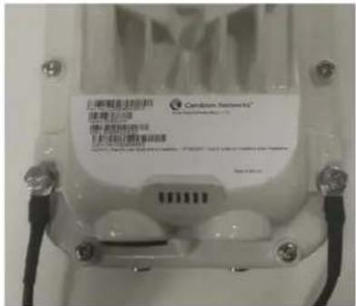
2 Tighten the Ground post screws.
natural_image
Close-up of a white cylindrical object with a black handle, possibly a device or container, against a blurred background (no visible text or symbols)3 Securely connect the copper wires to the grounding system (Protective Earth) and the LPU or Gigabit Ethernet Surge Suppressor according to applicable regulations.
PMP 450 AP
1 Fasten an AWG 10 (or 6mm²) copper ground cable to each ODU grounding point using the M6 (small) lugs
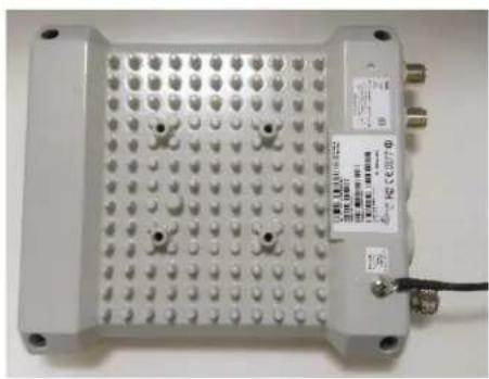
natural_image
White electronic device with grid of pins and connectors, no visible text or symbols on the main body.2 Tighten the Ground post locking nut in the copper wire

natural_image
Close-up of a white electronic device with multiple pins and a black cable attached (no visible text or symbols)3 Securely connect the copper wire to the grounding system (Protective Earth) according to applicable regulations.
PMP 450 SM
1 Fasten an AWG 10 (or 6mm ^2 ) copper ground cable to each ODU grounding point using the M6 (small) lugs

2 Tighten the Ground post locking nut in the copper wire

natural_image
Close-up of a white electronic device with a black cable inserted, no visible text or symbols3 Securely connect the copper wire to the grounding system (Protective Earth) according to applicable regulations.
The grounding point on PMP 450 Series SM 900 MHz is different from 2.4, 3.5/3.65 and 5 GHz PMP 450 SMs as shown in Figure 76.
Figure 76 PMP 450 900 MHz SM grounding

natural_image
Close-up of a white industrial sensor or monitoring device mounted on a metal frame, with cables and wiring visible (no readable text or symbols)Mount the ODU on the mast
PMP 450m Series - AP
1 See - PMP 450m Series - 5 GHz AP on page 6-57 for Installation for an integrated ODU
2 Remove the rear bracket strap from upper and lower brackets of ODU
3 Attach the upper and lower bracket of ODU to the mount point by closing the rear strap around the pole
4 Secure the four-serrated flange M8 nuts by applying 10 Nm torque on upper and lower rear strap using a 13 mm spanner wrench. These must be tightened evenly on the pole to avoid jumping/stripping threads

natural_image
Close-up of a metallic industrial transformer with visible cooling fins and wiring (no text or symbols)Secure the bolts on four sides by applying 8 Nm torque as per the angle of the antenna.
PMP/PTP 450i Series - AP/SM/BH, PMP 450 3 GHz Ruggedized SM

Caution
Do not reverse the bracket clamp, as this arrangement may lead to failure of the assembly. Do not over-tighten the bolts as this may lead to failure of the assembly.
1 Fix the mounting plate to the back of the ODU using the four bolts, and spring and plain washers provided. Tighten the bolts.
2 Attach the bracket body to the mounting plate using the M8 bolt, spring and plain washers.
3 Hoist the ODU to the mounting position
4 Attach the bracket body to the pole using the bracket clamp, M8 bolts, and spring and plain washers.
5 Adjust the elevation and azimuth to achieve visual alignment.
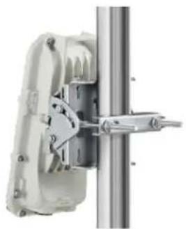
natural_image
Mechanical assembly with a vertical metal rod and mechanical components (no visible text or symbols)PMP 450b Mid-Gain SM
1 Use a stainless steel hose clamp for the attachment.
2 Attach the mounting bracket to the structure with the release tab facing downward. Tighten the hose clamp.
3 Slide the 450b SM onto the mounting bracket. Press downwards until it clicks into place.

natural_image
Two views of a mechanical device with attached clamps and a cylindrical body, shown from different angles (top: 30°, bottom: 25°) with no visible text or symbols.4 Loosen the adjuster wingnut on the bracket and set the required SM tilt angle. Retighten the adjuster wingnut by hand to secure the SM at the chosen angle.
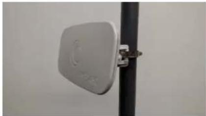
natural_image
Close-up of a white rectangular electronic device mounted on a vertical pole against a plain wall (no visible text or symbols)PMP 450b High Gain SM
1 Snap in the rear housing assembly.
2 Insert screws to hold the rear housing assembly to the dish by applying 5 Nm Torque.
3 Snap in the center feed tube to the assembly.

natural_image
Illustration of a circular device with a lid and a mechanical component, no text or symbols present.
natural_image
Circular object with a central red ring and several small dots, resembling a mechanical or electronic component (no text or symbols visible)
natural_image
3D rendering of a mechanical component with a circular housing and central hub, showing internal components (no text or symbols)4 Tighten the center feed tube lock screw.
5 Assemble the pole bracket to the Rear housing bracket.
6 Remove the cable gland from bottom cover. Feed the RJ45 cable though the gland, bottom cover and connect to the radio.

natural_image
Three technical illustrations of a mechanical device with internal components, shown from different angles (top, middle, bottom) without any text or symbols.7 Keep part loose and screw gland to the bottom cover. Audio cable is not shown in the figure.

natural_image
3D rendering of a mechanical device mounted on a circular surface, showing internal components and no visible text or symbols.8 Tighten gland, bottom cover screws and connect to the radio.
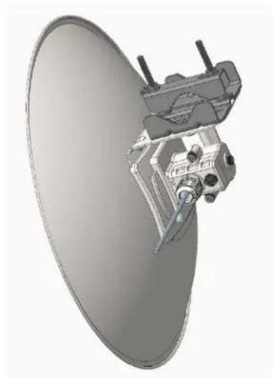
natural_image
3D rendering of a satellite dish mounted on a circular base, showing internal components and no visible text or symbols.9 Loosen M8 nuts to remove outer clamp. Slip clamp over pole and tighten M8 nuts by applying 8 Nm torque. Do not over tighten to prevent aligning the dish.

natural_image
3D rendering of a satellite dish antenna with a cylindrical base and internal structure (no text or symbols visible)PMP 450 AP
1 Using an 8mm nut driver, attach the pole mount's AP housing bracket to the unit using the 4 M5 x 16mm bolts included with the AP.
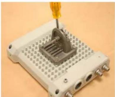
natural_image
Close-up of a mechanical component being inserted into a white plastic housing, with a yellow screwdriver inserted (no visible text or symbols)2 Using the included (depending on pole diameter):
- M8 x 70mm hex cap bolts (2 quantity) or
- M8 x 40mm hex cap bolts (2 quantity) and
• M8 flat washers (2 quantity)
• M8 coil washers (2 quantity)
Attach the mounting bracket to the pole/mast. The mounting bracket is designed to attach to poles with diameters in the range of 2 in. (50mm) to 3in. (75mm).

natural_image
Close-up of a metallic mechanical component with a bolted joint and cylindrical shaft (no visible text or symbols)3 Complete the AP mounting assembly by attaching the included:
• 8mm hex cap bolt (one quantity)
Through the AP's attached mounting bracket and pole mount. Now the AP may be adjusted to the desired position and tightened with a 1/2-inch spanner wrench to 11 lb/ft (14Nm).
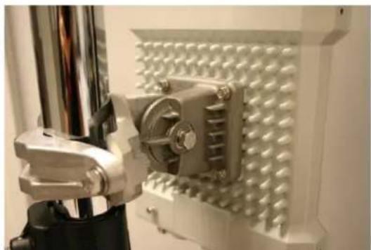
natural_image
Close-up of a mechanical device with a metallic component mounted on a white textured wall (no visible text or symbols)PMP 450 SM (except PMP 450 SM - 900 MHz)
1 Use stainless steel hose clamps for the attachment.
2 Attach the mounting bracket to the structure. Tighten the locking nut.

PMP 450 SM 900 MHz (connectorized)
The PMP 450 900 MHz connectorized SM mounting procedure is different from other radios. It does not get directly mounted on pole.
1 Align the 900 MHz SM to E bracket of Yagi antenna
2 Slide the radio towards right to lock on the antenna

natural_image
3D rendering of a gray industrial or agricultural sensor device mounted on a vertical pole, with no visible text or symbols.Slide towards right to lock
Mount the top LPU
1 For separate LPU mounting, use the U-bolt bracket from the LPU kit to mount the top LPU on the pole below the ODU. Tighten to a torque setting of 7.0 Nm (5.2 lb ft).
Please refer Gigabit LPU and Grounding Kit Installation Guide for more details.

natural_image
Close-up of a metallic mechanical component with threaded fastener and bolted joint (no visible text or symbols)Mount the Surge Suppressor
PMP/PTP 450i/450b Series
Gigabit Ethernet Surge Suppressors are installed at both ends of the drop cable. One within 600 mm (24") of and under the ODU. The other located within 600 mm (24") of the building entry point.
Quick procedure:
The quick procedure for the Surge Suppressor for PMP/PTP 450i/450b Series mounting is as follows:
1 Ground using the terminal on the back of the units. Use the supplied Tubular Lug and 6 mm2 (10 AWG) stranded cable, max length 600 mm (24").
I. Waterproof the cable lug with heat shrink sleeving.
II. Secure the Cable assembly to the unit using the supplied screw and washer.
2 Mount the Gigabit Ethernet Surge Suppressor on the wall or pole

natural_image
Close-up of a white electrical plug with attached cable and terminal block (no visible text or symbols)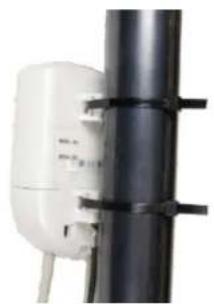
natural_image
Close-up of a white industrial electrical outlet mounted on a black cylindrical pole with black connectors (no visible text or symbols)3 Connect the two CAT5e cables to the Gigabit Ethernet Surge Suppressor
4 Slide the end cap over the bottom of the Gigabit Ethernet Surge Suppressor, ensuring it clicks firmly in place
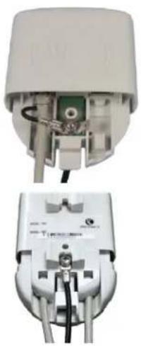
natural_image
Two views of a white electrical plug showing internal components and wiring (no text or symbols visible)Refer to the Gigabit Ethernet Surge Suppressor Installation Guide for more details.
Figure 77 Gigabit Ethernet Surge Suppressor

natural_image
Exterior view of a white industrial sensor device with attached circuit board and wiring, alongside its close-up of its internal components (no visible text or symbols)PMP/PTP 450 Series
The PMP/PTP 450 Series uses 600SSH Surge Suppressor. The inside of the surge suppressor is shown in Figure 78.

Caution
The PMP 450 SM 900 MHz is based off of the 450 Series, be sure to use a 600SS to protect this radio type.
Figure 78 600SSH Surge Suppressor - inside

Key to Callouts 600SSH
1 Holes—for mounting the Surge Suppressor to a flat surface (such as an outside wall). The distance between centers is 4.25 inches (108 mm).
2 RJ-45 connectors—One side (neither side is better than the other for this purpose) connects to the product (AP, SM, AC Adapter, or cluster management module). The other connects to the drop cable.
3 Ground post and washer—use heavy gauge (10 AWG or 6 mm ^4 ) copper wire for connection. Refer to local electrical codes for exact specifications.
4 Ground Cable Opening—route the 10 AWG (6 mm ^2 ) ground cable through this opening.
5 CAT-5 Cable Knockouts—route the two CAT-5 cables through these openings, or alternatively through the Conduit Knockouts.
6 Conduit Knockouts—on the back of the case, near the bottom. Available for installations where cable is routed through building conduit.

Note
The 600SSH surge suppressor is shipped in the “isolated” position (pin 4 isolated by 68V from protective earth). If packet error issues occur over the Ethernet link (verify by pinging the device through the 600SSH), configure the 600SSH to “grounded” position (by moving the 600SSH switch from “isolated” to “ground”) to avoid ground loops that may be present in the system.
The mounting procedure for the Surge Suppressor for PMP/PTP 450 Series is as follows:
1 Remove the cover of the 600SSH Surge Suppressor.
2 With the cable openings facing downward, mount the 600SSH to the outside of the subscriber premises, as close to the point where the Ethernet cable penetrates the residence or building as possible, and as close to the grounding system (Protective Earth) as possible.
3 Wrap an AWG 10 (or 6mm ^2 ) copper wire around the Ground post of the 600SSH.
4 Tighten the Ground post locking nut in the 600SSH onto the copper wire.
5 Securely connect the copper wire to the grounding system (Protective Earth) according to applicable regulations.
6 Using diagonal cutters or long nose pliers, remove the knockouts that cover the cable openings to the 600SSH.
7 Pack both surge suppressor Ethernet jacks with dielectric grease.
8 Wrap a splice loop in the loose end of the Ethernet cable from the SM.
9 Connect that cable to one of the Ethernet jacks.
10 Connect an Ethernet cable to the other Ethernet jack of the 600SSH and to the power adapter.
11 Replace the cover of the 600SSH.
General protection installation
To adequately protect a 450 Platform Family installation, both ground bonding and transient voltage surge suppression are required.
Grounding cable requirements
When routing, fastening and connecting grounding cables, the following requirements must be implemented:
- Grounding conductors must be run as short, straight, and smoothly as possible, with the fewest possible number of bends and curves.
• Grounding cables must not be installed with drip loops.
- All bends must have a minimum radius of 203 mm (8 in) and a minimum angle of 90° (Figure 79). A diagonal run is preferable to a bend, even though it does not follow the contour or run parallel to the supporting structure.
- All bends, curves and connections must be routed towards the grounding electrode system, ground rod, or ground bar.
• Grounding conductors must be securely fastened.
- Braided grounding conductors must not be used.
• Approved bonding techniques must be used for the connection of dissimilar metals.
Figure 79 Grounding cable minimum bend radius and angle


Caution
Do not attach grounding cables to the ODU mounting bracket bolts, as this arrangement will not provide full protection.
Basic requirements
The following basic protection requirements must be implemented:
- ODU must be in 'Zone B' (see Lightning protection zones on page 3-9).
- ODU must be grounded to the supporting structure.
- A surge suppression unit must be installed on the outside of the building.
- The distance between the ODU and Gigabit Surge Suppressor should be kept to a minimum.
- The drop cable must not be laid alongside a lightning air terminal.
- All grounding cables must be a minimum size of 10 mm ^2 csa (8AWG), preferably 16 mm ^2 csa (6AWG), or 25 mm ^2 csa (4AWG).
Protection requirements for a wall installation
If the ODU is to be mounted on the wall of a building, then in addition to the general protection requirements (above), the following requirements must be observed:
- The equipment must be lower than the top of the building or its lightning air terminal.
• The building must be correctly grounded.
Schematic examples of wall installations are shown in Figure 80.
Figure 80 Grounding and lightning protection on wall

Protection requirements for a mast or tower installation
If the ODU is to be mounted on a metal tower or mast, then in addition to the general protection requirements (above), the following requirements must be observed:
• The equipment must be lower than the top of the tower or its lightning air terminal.
• The metal tower or mast must be correctly grounded.
Schematic examples of mast or tower installations are shown in Figure 81.
Figure 81 Grounding and lightning protection on mast or tower

flowchart
graph TD
    A["Outdoor CAT5e cable"] --> B["AP/BHM"]
    C["Cat5e cable"] --> B
    D["Ground Cable"] --> B
    E["Tower/building ground system"] --> B
    B --> F["Equipment building"]
    F --> G["Power supply"]
    G --> H["Network switch"]
    I["External ground bar"] --> J["Ground ring"]
Protection requirements on a multi-floor building
If the ODU is to be mounted on a high-rise building, it is likely that cable entry is at roof level (Figure 48) and the equipment room is several floors below. The following additional requirements must be observed:
• The ODU must be below the lightning terminals and finials.
- A grounding conductor must be installed around the roof perimeter to form the main roof perimeter lightning protection ring.
- Air terminals are typically installed along the length of the main roof perimeter lightning protection ring typically every 6.1m (20ft).
- The main roof perimeter lightning protection ring must contain at least two down conductors connected to the grounding electrode system. The down conductors should be physically separated from one another, as far as practical.
Figure 82 Grounding and lightning protection on building

flowchart
graph TD
    A["AP"] --> B["Gigabit Surge Suppressor"]
    B --> C["Ground to opposite-side ODU grounding lug"]
    C --> D["Power Supply"]
    D --> E["Network switch"]
    E --> F["To building ground ring"]
    style A fill:#f9f,stroke:#333
    style B fill:#ccf,stroke:#333
    style C fill:#cfc,stroke:#333
    style D fill:#fcc,stroke:#333
    style E fill:#cff,stroke:#333
    style F fill:#ffc,stroke:#333
Installing the copper Cat5e Ethernet interface
To install the copper Cat5e Ethernet interface, use the following procedures:
• Install the main drop cable on page 6-22
• Install the bottom LPU to PSU drop cable on page 6-25
• Installing external antennas to a connectorized ODU on page 6-27

Caution
To avoid damage to the installation, do not connect or disconnect the drop cable when power is applied to the PSU or network terminating equipment.

Caution
Always use Cat5e cable that is gel-filled and shielded with copper-plated steel. Alternative types of Cat5e cable are not supported by Cambium Networks. Cambium Networks supply this cable (Cambium part numbers WB3175 and WB3176), RJ45 connectors (Cambium part number WB3177) and a crimp tool (Cambium part number WB3211). The LPU and grounding kit contains a 600-mm length of this cable.
Install the main drop cable

Warning
The metal screen of the drop cable is very sharp and may cause personal injury.
- ALWAYS wear cut-resistant gloves (check the label to ensure they are cut resistant).
• ALWAYS wear protective eyewear. - ALWAYS use a rotary blade tool to strip the cable (DO NOT use a bladed knife).

Warning
Failure to obey the following precautions may result in injury or death:
- Use the proper hoisting grip for the cable being installed. If the wrong hoisting grip is used, slippage or insufficient gripping strength will result.
- Do not reuse hoisting grips. Used grips may have lost elasticity, stretched, or become weakened. Reusing a grip can cause the cable to slip, break, or fall.
- The minimum requirement is one hoisting grip for each 60 m (200 ft) of cable.
Cut to length and fit hoisting grips
1 Cut the main drop cable to length from the top LPU to the bottom LPU.
2 Slide one or more hoisting grips onto the top end of the drop cable.
3 Secure the hoisting grip to the cable using a special tool, as recommended by the manufacturer.
Terminate with RJ45 connectors

Caution
Check that the crimp tool matches the RJ45 connector, otherwise the cable or connector may be damaged.
1 Strip the cable outer sheath and fit the RJ45 connector load bar.
2 Fit the RJ45 connector housing as shown. To ensure there is effective strain relief, locate the cable inner sheath under the connector housing tang.
Table 112 RJ45 connector and cable color code
| Pin | Color (Supplied cable) | Color (Conventional) | Pins on plug face |
| 1 | Light Orange White/Orange | 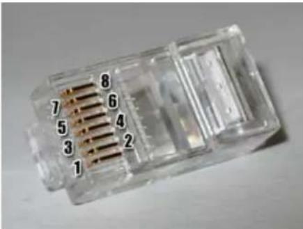 | |
| 2 | Orange Orange | ||
| 3 | Light Green White/Green | ||
| 4 | Blue Blue | ||
| 5 | Light Blue White/Blue | ||
| 6 | Green Green | ||
| 7 | Light Brown White/Brown | ||
| 8 | Brown Brown |
Figure 83 RJ45 cable

Install the bottom LPU to PSU drop cable
Install the bottom LPU
Install the bottom LPU, ground it, and connect it to the main drop cable.
1 Select a mounting point for the bottom LPU within 600 mm (24 in) of the building entry point. Mount the LPU vertically with cable glands facing downwards.
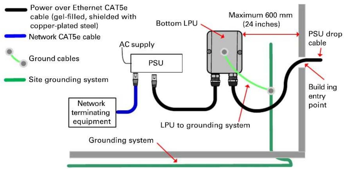
flowchart
graph TD
    A["Power over Ethernet CAT5e cable (gel-filled, shielded with copper-plated steel)"] --> B["Network CAT5e cable"]
    B --> C["Ground cables"]
    C --> D["Site grounding system"]
    D --> E["Grounding system"]
    E --> F["PSU dropping cable"]
    F --> G["LPU to grounding system"]
    G --> H["AC supply"]
    H --> I["PSU"]
    I --> J["Maximum 600 mm (24 inches)"]
    J --> K["Power over Ethernet CAT5e cable"]
    style A fill:#f9f,stroke:#333
    style B fill:#bbf,stroke:#333
    style C fill:#f9f,stroke:#333
    style D fill:#f9f,stroke:#333
    style E fill:#f9f,stroke:#333
    style F fill:#f9f,stroke:#333
    style G fill:#f9f,stroke:#333
    style H fill:#f9f,stroke:#333
    style I fill:#f9f,stroke:#333
    style J fill:#f9f,stroke:#333
    style K fill:#f9f,stroke:#333
2 Connect the main drop cable using the EMC cable gland to the bottom LPU.
3 Fasten one ground cable to the bottom LPU using the M6 (small) lug. Tighten both nuts to a torque of 5 Nm (3.9 lb ft):
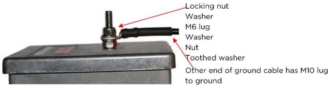
4 Select a building grounding point near the LPU bracket. Remove paint from the surface and apply anti-oxidant compound. Fasten the LPU ground cable using the M10 (large) lug.
Install the LPU to PSU drop cable
Use this procedure to terminate the bottom LPU to PSU drop cable with RJ45 connectors at both ends, and with a cable gland at the LPU end.

Warning
The metal screen of the drop cable is very sharp and may cause personal injury. ALWAYS wear cut-resistant gloves (check the label to ensure they are cut resistant). ALWAYS wear protective eyewear. ALWAYS use a rotary blade tool to strip the cable, not a bladed knife.

Caution
Check that the crimp tool matches the RJ45 connector, otherwise the cable or connector may be damaged.
1 Cut the drop cable to the length required from bottom LPU to PSU.
2 At the LPU end only:
- Fit one cable gland and one RJ45 connector by following the procedure Terminate with RJ45 connectors on page 6-23.
- Connect this cable and gland to the bottom LPU.
3 At the PSU end only: Do not fit a cable gland. Strip the cable outer sheath and fit the RJ45 connector load bar. Fit the RJ45 connector housing. To ensure there is effective strain relief, locate the cable inner sheath under the connector housing tang:

Installing external antennas to a connectorized ODU
PMP 450i Series
To mount and connect an external antenna to the connectorized ODU, proceed as follows:
1 Mount the antenna(s) according to manufacturer's instructions.
2 Connect the ODU A and B interfaces to the antenna(s) with RF cable of type LMR-400 (Cambium part numbers 30010194001 and 30010195001) and N type connectors (Cambium part number 09010091001). Tighten the N type connectors to a torque setting of 1.7 Nm (1.3 lb ft).
3 If the ODU is mounted indoors, install lightning arrestors at the building entry point:
4 Form drip loops near the lower ends of the antenna cables. These ensure that water is not channeled towards the connectors.
5 If the ODU is mounted outdoors, weatherproof the N type connectors (when antenna alignment is complete) using PVC tape and self-amalgamating rubber tape.
6 Weatherproof the antenna connectors in the same way (unless the antenna manufacturer specifies a different method).
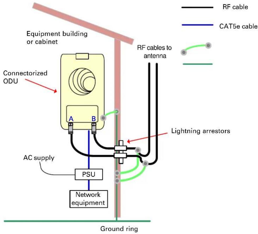
7 Ground the antenna cables to the supporting structure within 0.3 meters (1 foot) of the ODU and antennas using the Cambium grounding kit (part number 01010419001):

8 Fix the antenna cables to the supporting structure using site approved methods. Ensure that no undue strain is placed on the ODU or antenna connectors. Ensure that the cables do not flap in the wind, as flapping cables are prone to damage and induce unwanted vibrations in the supporting structure.

Note
A video on weatherproofing procedure can be found at:
https://www.youtube.com/watch?v=a-twPfCVq4A
Assembling the PMP 450i AP 5 GHz sector antenna and attaching to the radio
To assemble a PMP 450i Series AP antenna, perform the following steps.

Note
Cambium recommends assembling the antenna, attach the AP and cabling, and to seal the RF connections before installing the unit at the deployment site.
1 Inventory the parts to ensure that you have them all before you begin. The full set of parts is shown below.
Figure 84 AP antenna parts
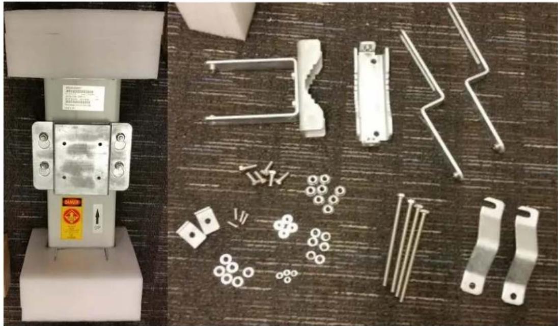
natural_image
Two-panel image showing a white electrical switch device and various metal components laid out on a carpet (no visible text or symbols)2 Remove top plate from the antenna as shown in Figure 85.
Figure 85 Antenna top plate
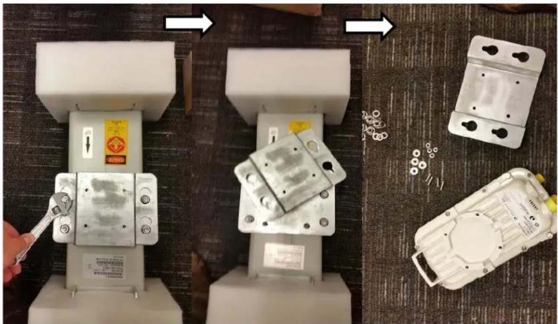
natural_image
Three-panel image showing a robotic arm operating on a device, with a close-up of its internal components and a close-up of a mechanical housing (no visible text or symbols)3 Attach the antenna plate to the AP as shown in Figure 86.

Note
Please use the four "thin neck" M6 bolts and split washers provided with the connectorized units rather than the ones provided in the antenna kit.
Figure 86 Attaching antenna plate to the AP

natural_image
Three-panel photo showing a metal electrical enclosure with bolts and mounting holes, arranged horizontally (no text or symbols visible)4 Attach the plate mounted AP to the antenna and tighten the (4) serrated flange nuts using a spanner wrench
Figure 87 Attaching the plate

natural_image
Three-panel photo showing a sewing machine with attached components and a hand adjusting the base (no visible text or symbols)5 Connect the port A of AP to vertical and port B of AP to horizontal polarization interfaces of the antenna with RF cable. Tighten the N type connectors to a torque setting of 1.7 Nm (1.3 lb ft).
Figure 88 Connect the port A and B to the PMP 450i AP
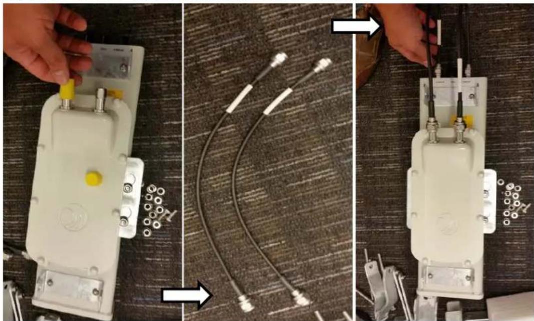
natural_image
Three-panel image showing a hand operating a white electronic device, connected to a coiled cable and a wire assembly (no visible text or symbols)6 Assemble the upper bracket by attaching the (2) 7" hex bolts to the bracket using (2) serrated flange nuts
Figure 89 AP antenna upper bracket assembly

natural_image
Metallic electronic component with two metal pins and a central metallic piece, shown against a brown surface (no text or symbols visible)7 Attach the upper bracket to the adjustment arms using (2) hex bolts, (2) flat washers and (2) lock washers. Feed the bolt through the lock washer then flat washer, then thread the bolt into the upper bracket's threaded receptacle.
Figure 90 AP antenna upper bracket attached to upper adjustment arms

natural_image
Metal mechanical clamp bracket with two metal arms and a central rectangular housing, placed on a wooden surface (no text or symbols visible)8 Attach the rear strap to the upper bracket using (2) serrated flange nuts and (1) retaining bracket. Do not tighten the nuts now.
Figure 91 Rear strap connected to upper AP antenna bracket

natural_image
Metallic mechanical component with flanged ends and bolted joints (no visible text or symbols)9 Attach the entire upper bracket to the antenna using (2) hex bolts, (2) flat washers and (2) lock washers. Feed the bolt through the lock washer then flat washer, then thread the bolt into the upper bracket's threaded receptacle.
Figure 92 Assembled upper bracket connected to AP antenna
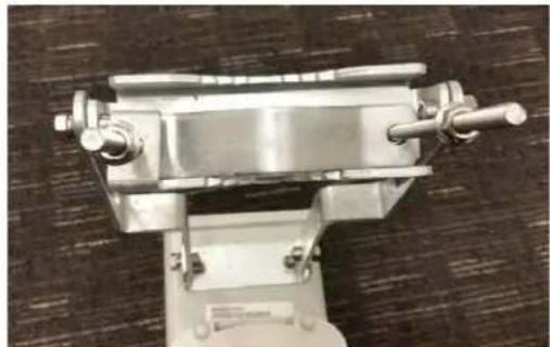
natural_image
Close-up of a metallic mechanical device with two protruding rods and a central shaft, placed on a textured surface (no visible text or symbols)10 Begin assembling the lower bracket by attaching the (2) 7" hex bolts to the bracket using (2) serrated flange nuts
Figure 93 AP Antenna Lower Bracket Assembly

natural_image
Close-up of a metallic mechanical clamp or bracket with metal plates and two vertical rods (no visible text or symbols)11 Attach the rear strap to the bracket using (2) serrated flange nuts and (1) retaining bracket. Do not tighten the nuts now.
Attach the entire lower bracket to the antenna using (2) hex bolts, (2) flat washers and (2) lock washers.
Figure 94 Lower bracket attached to AP antenna

natural_image
Mechanical clamp device with metal components and wiring on a textured surface (no visible text or symbols)Figure 95 Completed AP and antenna assembly

natural_image
Mechanical device with articulated arms and a yellow component, placed on a blue carpet (no visible text or symbols)PMP 450 Series
Assembling the PMP 450 AP antenna
To assemble a PMP 450 Series AP antenna, perform the following steps.

Note
Cambium recommends assembling the antenna, attach the AP and cabling, and to seal the RF connections before installing the unit at the deployment site.
1 Inventory the parts to ensure that you have them all before you begin. The full set of parts is shown below.
Figure 96 PMP 450 AP antenna parts
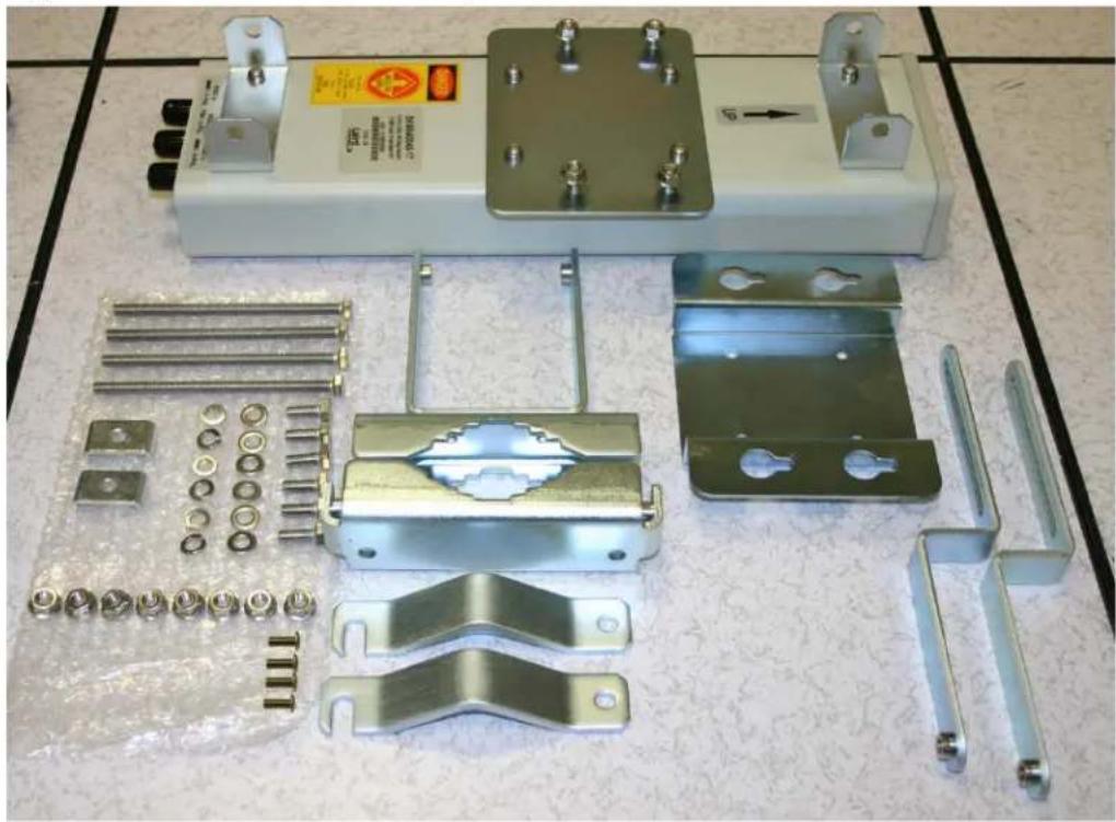
natural_image
Collection of metal automotive components laid out on a patterned surface, including battery pack, bracket, and mounting brackets (no visible text or symbols)2 Begin assembling the upper bracket by attaching the (2) 7" hex bolts to the bracket using (2) serrated flange nuts
Figure 97 AP antenna upper bracket assembly

natural_image
Metallic electronic component with two metal pins and a U-shaped groove, shown against a brown background (no text or symbols visible)3 Attach the upper bracket to the adjustment arms using (2) hex bolts, (2) flat washers and (2) lock washers. Feed the bolt through the lock washer then flat washer, then thread the bolt into the upper bracket's threaded receptacle.
Figure 98 AP antenna upper bracket attached to upper adjustment arms

natural_image
Metal bracket with two metal clips and a central support, placed on a wooden surface (no text or symbols visible)4 Attach the rear strap to the upper bracket using (2) serrated flange nuts and (1) retaining bracket. Do not tighten the nuts now.
Figure 99 Rear strap connected to upper AP antenna bracket

natural_image
Metallic mechanical clamp or bracket component with bolts and a V-shaped groove (no text or symbols visible)5 Attach the entire upper bracket to the antenna using (2) hex bolts, (2) flat washers and (2) lock washers. Feed the bolt through the lock washer then flat washer, then thread the bolt into the upper bracket's threaded receptacle.
Figure 100 Assembled upper bracket connected to AP antenna
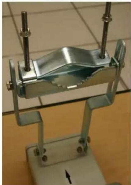
natural_image
Metal mechanical clamp device with metal plates and bolts, mounted on a base (no visible text or symbols)6 Begin assembling the lower bracket by attaching the (2) 7" hex bolts to the bracket using (2) serrated flange nuts
Figure 101 AP Antenna Lower Bracket Assembly
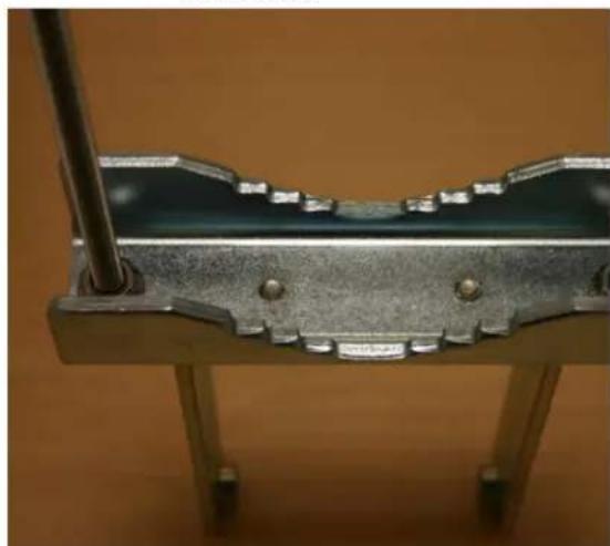
natural_image
Close-up of a metallic mechanical component with a U-shaped groove and internal grooves, mounted on a stand (no visible text or symbols)7 Attach the rear strap to the bracket using (2) serrated flange nuts and (1) retaining bracket. Do not tighten the nuts now.
Attach the entire lower bracket to the antenna using (2) hex bolts, (2) flat washers and (2) lock washers.
Figure 102 Lower bracket attached to AP antenna

natural_image
Close-up of a metallic mechanical clamp or fixture mounted on a stand, with no visible text or symbols.Attaching the PMP 450 AP to the antenna
To attach a PMP 450 Series AP to the antenna, perform the following steps.

Note
Use shielded cable for all infrastructure connections associated with APs, SMs, and CMMs. The environment that these modules operate in often has significant unknown or varying RF energy. Operator experience consistently indicates that the additional cost of shielded cables is more than compensated by predictable operation and reduced costs for troubleshooting and support.
1 Attach the included bracket to the rear of the AP using the (4) M5 x 7mm bolts
Figure 103 Attaching bracket to the rear of the AP

natural_image
Close-up of a metallic mechanical clamp or bracket with metal components and connectors (no visible text or symbols)2 Attach the AP to the antenna by sliding the bracket onto the bolts and tighten the (4) serrated flange nuts using a 13-mm spanner wrench.
Figure 104 Lower bracket attached to AP antenna

natural_image
White electronic device with a circular pattern on its side, mounted on a metal frame (no visible text or symbols)
Note
If using a non-standard antenna, do not cover the equilibrium membrane vent located on the back of the unit.
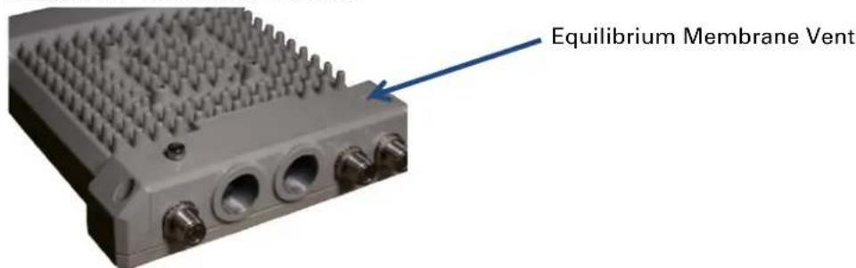
Figure 105 Mounted PMP 450 AP and antenna assembly, viewed from back and back

natural_image
Mechanical device with metallic arms and a beige central component, no visible text or symbols
natural_image
Industrial robotic device with mounted sensors and wiring (no visible text or symbols)Attaching the PMP 450 Series AP and antenna to the mount point
1 Attach the upper bracket of the antenna to the mount point by closing the rear strap around the pole and tightening the (2) serrated flange nuts using a 13mm spanner wrench. These must be tightened evenly on the pol to avoid jumping/stripping threads.
Figure 106 Attaching the AP antenna upper bracket to the pole

natural_image
Close-up of a metallic mechanical clamp or clamping device with two metal rods inserted (no visible text or symbols)2 Attach the lower bracket of the antenna to the mount point by closing the rear strap around the pole and tightening the (2) serrated flange nuts using a 13mm spanner wrench. These must be tightened evenly on the pole to avoid jumping/stripping threads.
Figure 107 Attaching the AP antenna lower bracket to the pole

natural_image
Close-up of a mechanical clamp or clamping device with metallic rods and a metallic housing (no visible text or symbols)3 Use a local map, compass, and/or GPS device as needed to determine the direction that one or more APs require to each cover the 90° sector.
4 Choose the best mounting location for your particular application.

Note
Use the embedded spectrum analyzer or a commercial analyzer to evaluate the frequencies present in various locations. OFDM APs need not be mounted next to each other. They can be distributed throughout a given site. However, the 90° offset must be maintained. If you want to collocate these APs with PMP 100 Series APs of the 5.4-GHz frequency band range, plan to allow at least 25 MHz of separation between their center channels.
5 Secure a ground strap to the ground lug on the back of the AP.
6 Secure the ground strap to the pole, tower, or other trusted ground.
7 The bracket of the standard antenna has provision for measured down tilt. The recommended practice is to use one of the many radio analysis and mapping tools or on-line tools to calculate down tilt based on antenna height above the service area.
The proper angle of tilt can be calculated as a factor of both the difference in elevation and the distance that the link spans. Even in this case, a plumb line and a protractor can be helpful to ensure the proper tilt. This tilt is typically minimal.
The number of degrees to offset (from vertical) the mounting hardware leg of the support tube is equal to the angle of elevation from the lower module to the higher module (<B in the example provided in Figure 71).
Figure 108 Variables for calculating angle of elevation (and depression)

Where: Is:
b angle of elevation
B vertical difference in elevation
A horizontal distance between modules
To use metric units to find the angle of elevation, use the following formula:
$$ \tan b = \frac {B}{1 0 0 0 A} $$
Where: Is:
B expressed in meters
A expressed in kilometers
To use English standard units to find the angle of elevation, use the following formula:
$$ \tan b = \frac {B}{5 2 8 0 A} $$
Where: Is:
B expressed in feet
A expressed in miles
The angle of depression from the higher module is identical to the angle of elevation from the lower module.
8 Connect the coax cables to the antenna and to the AP
9 Weatherproof the connector on the coax cables (see section Attaching and weatherproofing an N type connector on page 6-79).
PMP 450i Series AP 900 MHz
Mounting of PMP 450i AP 900 MHz
1 Inventory the parts to ensure that you have them all before you begin. The full set of parts is shown in Figure 110.
Figure 109 PMP 450i AP 900 MHz antenna unbox view

natural_image
Two 3D renderings of a cylindrical electronic device casing, one showing internal components and the other with mounting brackets (no text or symbols)Figure 110 PMP 450i AP 900 MHz antenna inventory

2 (1) Unfold the upper bracket assembly of the antenna.

natural_image
3D rendering of a remote control panel with a blue arrow indicating rotation (no text or symbols)1
(2) Unfold the lower bracket assembly.
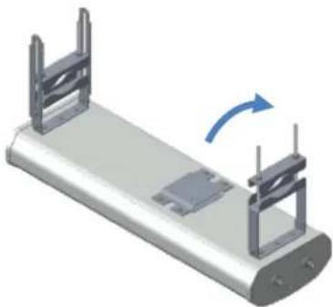
natural_image
3D diagram of a mechanical component with two metal supports and a blue rotation arrow indicating motion (no text or symbols)2
(3) Loose the radio assembly plate by untightening M8 four bold.

natural_image
3D mechanical assembly diagram showing a metal plate mounted on a bracket with a cylindrical pin inserted (no text or symbols visible)3
(4) Remove the radio assembly top plate by sliding towards upper bracket assembly.
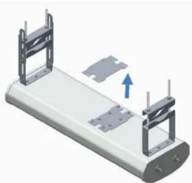
natural_image
3D rendering of a mechanical component with two metal supports and a blue arrow indicating direction (no text or symbols)4
3 (1) Place the radio assembly plate on the radio and align holes with radio enclosure.

Note
Ensure that the radio plate notch opening and RF port of radio in same direction. It is also important to make sure you attach the radio assembly plate in the proper orientation as shown in figure.
(2) Insert M6 bolts through plate into radio enclosure
(3) Fix the plate by tightening four bolts with a torque setting on 2 ± 0.5 Nm
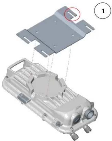
natural_image
3D mechanical assembly diagram showing a component with mounting plate and housing, no visible text or symbols
natural_image
3D rendering of a mechanical component with mounting holes and internal structure (no visible text or symbols)
natural_image
3D rendering of a mechanical component with mounting holes and a metal bracket (no text or symbols visible)4 (1) Place the radio mounted plate on sector antenna as shown in the figure. Ensure that the orientation of RF port of antenna and radio are in same direction

natural_image
3D mechanical assembly diagram showing a housing with metal supports and a small component, labeled with number 1 (no text or symbols on the diagram itself)(2) Line up the radio assembly to four bolts and slide towards lower bracket assembly to lock.
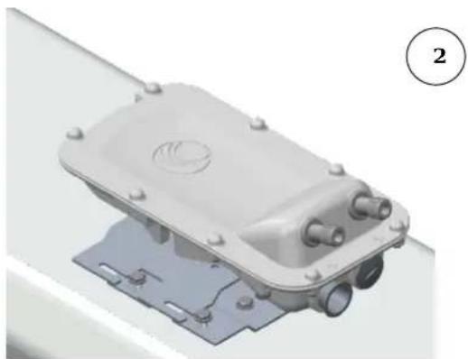
natural_image
3D rendering of a mechanical component with mounting base and internal features (no text or symbols visible)(3) Tighten the radio assembly plate using four M8 bolts to a torque setting of 2 ± 0.5 Nm

natural_image
3D rendering of a mechanical component with mounting flanges and a circular feature, no visible text or symbols5
(1) Connect the port A of AP to vertical and port B of AP to horizontal polarization interfaces of the antenna with RF cable. Ensure that the RF cables are pass-through inside the lower bracket assembly

(2) Hand tighten the N type connectors and the torque should not exceed more than 1 Nm

natural_image
3D rendering of a mechanical assembly with metal supports and a central component, labeled with number 2 (no text or symbols on the diagram itself)Mounting of PMP 450i AP 900 MHz antenna to the pole
The mounting procedure of PMP 450i AP 900 MHz and antenna to the pole is given below:
1 Remove the upper and lower rear bracket strap from the sector antenna.

natural_image
3D rendering of a vehicle chassis with support structures and mounting brackets (no text or symbols visible)2 Attach the upper and lower bracket of the antenna to the mount point by closing the rear strap around the pole.

Note
Before mounting the radio on the pole, secure the upper and lower bracket assemblies with a torque setting of 3 to 4 Nm as shown in Figure 1. Also, ensure that inner strap of upper bracket is set to zero-degree marking.
Figure 111 Attaching radio mounting PMP 450i AP 900 MHz antenna to the pole

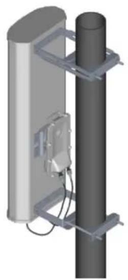
natural_image
3D rendering of a vertical cylindrical device mounted on a metal frame, with no visible text or symbols.3
3 Tighten the four-serrated flange M10 nuts on the upper and lower rear straps using a 17 mm spanner wrench. These must be tightened evenly on the pole to avoid jumping/stripping threads

Sector antenna alignment
The 900 MHz sector antenna horizontal and vertical alignment procedure is shown in Figure 112. The antenna can be aligned from +5 to -10 degree by adjusting the inner strap of the upper bracket assembly.
Figure 112 900 MHz sector antenna alignment
Horizontal alignment
Inner strap
Vertical alignment
downward tilt
Vertical alignment
upward tilt

Building ground system
PMP 450 Series SM 900 MHz
Attaching the SM 900 MHz directional antenna to the pole
1 Unbox the directional Yagi antenna.
Figure 113 PMP 450i SM 900 MHz external directional antenna

natural_image
3D rendering of a long, multi-axle antenna with multiple blades and a base mount (no text or symbols visible)2 Attach the directional antenna to the pole and insert the two U clamps into the mounting bracket of the antenna
Figure 114 Attach the antenna to the pole

natural_image
Two identical 3D diagrams of a long antenna mounted on cylindrical poles, showing structural components and wiring (no text or symbols)3 Tighten all nuts to approximately 6 to 7 Nm or less to avoid deforming the pole.
Figure 115 Fixing the nuts

natural_image
3D rendering of a long, multi-barrel antenna mounted on a cylindrical base (no text or symbols visible)Radio mounting to the antenna
1 Align the radio to E bracket and slide towards right to lock on the antenna as shown in figure.
Figure 116 Fixing the radio to the antenna

natural_image
3D rendering of a modern antenna with vertical and horizontal axis components (no text or symbols visible)Slide towards right to lock
2 Connect the port A of SM to vertical and port B of SM to horizontal polarization interfaces of the antenna with RF cable.
Figure 117 Connecting RF cable to the radio
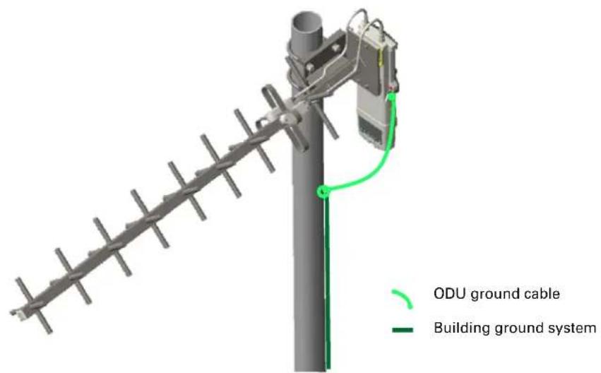
Directional Yagi antenna alignment
The directional Yagi antenna horizontal and vertical alignment procedure is shown below. The Yagi antenna can be aligned for +15 to -15 degree.
Figure 118 Yagi antenna alignment - horizontally

natural_image
Diagram of a vertical antenna with a green cable and wiring, no text or symbols presentFigure 119 Yagi antenna alignment - upward tilt

natural_image
3D rendering of a long antenna with multiple side connectors and a green cable, mounted on a vertical pole (no text or symbols visible)Figure 120 Yagi antenna alignment - downward tilt

natural_image
3D diagram of a vertical antenna with a green line indicating a connection point (no text or symbols present)Installing an integrated ODU

Caution
Do not reverse the bracket clamp, as this arrangement may lead to failure of the assembly. Do not over-tighten the bolts as this may lead to failure of the assembly.
PMP 450m Series - 5 GHz AP
To mount and connect an integrated ODU, proceed as follows:
1 Inventory the parts to ensure that you have them all before you begin. The full set of parts is shown in Figure 121.
Figure 121 PMP 450m Series - 5 GHz AP unbox view

natural_image
Interior view of an electronic device casing with metallic cooling fins and mounting holes (no text or symbols visible)PMP 450m AP

natural_image
Exploded view diagram of a mechanical assembly with mounting holes and structural components (no text or labels)Top bracket
(Additional nuts)
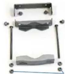
natural_image
Mechanical assembly diagram showing a bracket, mounting base, and clamping elements (no text or labels)Bottom bracket
(Additional nuts)

Note
The additional nuts provided for top and bottom brackets are used to hold the long bolts in position during installation.
2 Attach the bottom bracket to the ODU using (2) hex bolts and secure the M8 bolts by applying 5 Nm torque.

natural_image
Two views of an electronic device casing showing internal components and mounting hardware (no visible text or symbols)3 Attach the top bracket to the projecting studs on the ODU and secure the top bracket using two M8 nuts by applying 5 Nm torque.

natural_image
Two views of an electronic component with metallic housing and a metal bracket, placed on a grid-patterned surface (no visible text or symbols)4 Fix the front and rear strap assembly to the upper bracket using two bolts. Do not tighten the nuts now.

natural_image
Close-up of a metallic electronic component with internal structural brackets and heat sink (no visible text or symbols)Note: The PMP 450m antenna operates with 2 degrees of electrical down-tilt.
5 Fix the front and rear strap assembly to the bottom bracket using two bolts. Do not tighten the nuts now.

natural_image
Close-up of a metallic vehicle chassis with mounting feet and internal components (no visible text or symbols)6 See PMP 450m Series - AP on page 6-3 for the grounding procedure.
See PMP 450m Series - AP on page 6-6 for the mounting procedure.
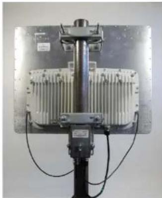
natural_image
Close-up of a mechanical device with a metallic frame and mounted cylindrical component (no visible text or symbols)PMP 450m Series - 3 GHz AP
To mount and connect an integrated ODU, proceed as follows:
1 Inventory the parts to ensure that you have them all before you begin. The full set of parts is shown in Figure 121.
Figure 122 PMP 450m Series - 3 GHz AP unbox view

natural_image
Metallic industrial component with multiple vertical fins and mounting holes (no visible text or symbols)PMP 450m AP - 3 GHz
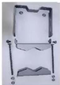
natural_image
Mechanical component with mounting brackets and mounting holes (no text or symbols visible)Top bracket

natural_image
Mechanical component with a hinged frame and mounting holes (no visible text or symbols)Bottom bracket

Note
The additional nuts provided for top and bottom brackets are used to hold the long bolts in position during installation.
2 Attach the bottom bracket to the ODU using (2) hex bolts and secure the M8 bolts by applying 5 Nm torque.
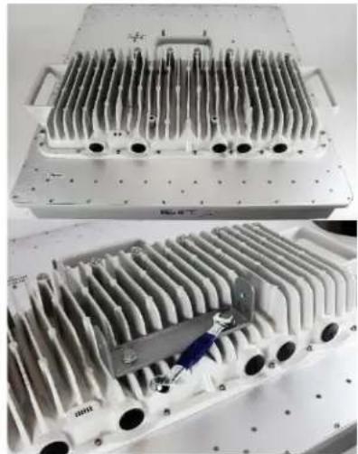
natural_image
Two views of a metallic industrial heat exchanger housing with internal cooling fins and mounting flanges (no text or symbols visible)3 Attach the top bracket to the projecting studs on the ODU and secure the top bracket using two M8 nuts by applying 5 Nm torque.

natural_image
Two views of an electrical power grid device: top shows a U-shaped bracket with labeled 'ELECTRICAL POWER FIT.' and bottom shows a metallic cooling unit with heat sinks (no readable text beyond label)4 Fix the front and rear strap assembly to the upper bracket using two bolts. Do not tighten the nuts now.
Note: The PMP 450m antenna operates with 2 degrees of electrical down-tilt.

natural_image
Mechanical component with metal frame and grid base, no visible text or symbols5 Fix the front and rear strap assembly to the bottom bracket using two bolts. Do not tighten the nuts now.
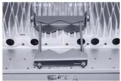
natural_image
Close-up of a mechanical or electronic component with multiple circular components and a central metallic housing (no visible text or symbols)6 See PMP 450m Series - AP on page 6-3 for the grounding procedure.
See PMP 450m Series - AP on page 6-6 for the mounting procedure.
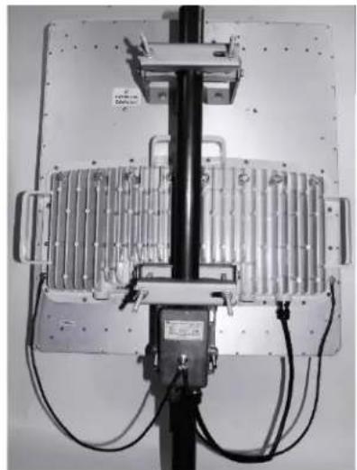
natural_image
Close-up of a mechanical or electronic device with metallic components and wiring (no visible text or symbols)PMP/PTP 450i Series - AP/SM/BH
To mount and connect an integrated ODU, proceed as follows:
1 Fix the mounting plate to the back of the ODU using the four M6 bolts, and spring and plain washers provided. Tighten the bolts to a torque setting of 5.0 Nm (3.7 lb ft).
Figure 123 Fixing the mounting plate to the back of the ODU
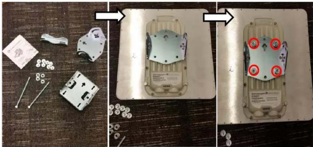
natural_image
Three-panel photo showing a device on a metal tray, with disassembled parts and a close-up of the device's top panel (no visible text or symbols)2 Attach the bracket body to the mounting plate using the M8 bolt, spring and plain washers.
3 Hoist the ODU to the mounting position.
4 Attach the bracket body to the pole using the bracket clamp, M8 bolts, and spring and plain washers.
5 If the ODU is mounted outdoors, weatherproof the N type connectors (when antenna alignment is complete) using PVC tape and self-amalgamating rubber tape.
Figure 124 Attaching the bracket body

natural_image
Close-up of a metal electrical connector with attached metal bracket and screw fasteners, shown from two angles (no visible text or symbols)Connecting Cat5e Ethernet cable
Connecting an RJ45 and gland to a unit
Perform this task to connect the Ethernet cable to an AP.
To connect the Ethernet cable with a gland to an AP unit, proceed as follows:
1 Insert the RJ45 cable through the gland components
2 Insert the RJ45 plug into the socket in the unit, making sure that the locking tab snaps home.
3 Support the drop cable and gently hand screw the gland body into the unit until the bushing seal is flush to the unit body.

Note
Do not fit the back shell prior to securing the gland body.
4 Once the gland is fully hand screwed into the unit, tighten it one full rotation only with a 11/8 inch spanner wrench.
5 When the gland body has been fitted, tighten the gland back shell.

Caution
Do not over-tighten the gland back shell, as the internal seal and structure or RJ45 port may be damaged.
Figure 125 Ethernet cable gland for PMP/PTP 450 Series

natural_image
Close-up of a RJ48 connector with internal wiring and socket, shown from three different angles (no text or symbols visible)Figure 126 Ethernet cable gland for PMP/PTP 450i Series
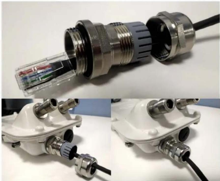
natural_image
Close-up of a metallic pipe fitting with internal components, shown from three different angles (top, front, side), no text or symbols visible.Disconnecting an RJ45 and gland from a unit
To disconnect the Ethernet cable and gland from a unit, proceed as follows:
1 Hold the Ethernet cable and remove the gland back shell.
2 Use a small flathead screwdriver (0.2"/5mm wide or greater) to gently release the black plastic watertight bushing from the compression fins, being careful not to damage the bushing.
3 Unscrew the gland body from the AP, making sure that the Ethernet cable is not rotating while disengaging the gland body from the AP housing.
4 Use a small screwdriver to depress the RJ45 locking clip.
5 Unplug the RJ45 cable.
6 Remove the gland from the cable, if necessary.
Installing ODU
Installing a 450 Platform Family AP
To install a 450 Platform Family AP, perform the following steps.
Procedure 5 Installing an AP
1 Begin with the AP in the powered-down state.
2 Choose the best mounting location for your particular application. Modules need not be mounted next to each other. They can be distributed throughout a given site. However, the 60° offset must be maintained. Mounting can be done with supplied clamps.
See Installing external antennas to a connectorized ODU on page 6-27 for connecting an external antenna to PMP 450i Series, PMP 450 Series, PMP 450i Series AP 900 MHz and PMP 450 Series SM
See Installing an integrated ODU on page 6-57
3 Align the AP as follows:
a. Move the module to where the link will be unobstructed by the radio horizon and no objects penetrate the Fresnel zone.
b. Use a local map, compass, and/or GPS device as needed to determine the direction that one or more APs require to each cover the intended 60° sector.
c. Apply the appropriate degree of downward tilt.
d. Ensure that the nearest and furthest SMs that must register to this AP are within the beam coverage area.
4 Adjust the azimuth to achieve visual alignment, lock the AP in the proper direction and downward tilt.
5 Attach the cables to the AP (See Powering the AP/SM/BH for test configuration on Page 5-17)
6 Waterproof the cables (See section Attaching and weatherproofing an N type connector on page 6-79).
Installing a 450 Platform Family SM
Installing a 450 Platform Family SM consists of two procedures:
- Physically installing the SM on a residence or other location and performing a coarse alignment using the alignment tool or alignment tone.
- Verifying the AP to SM link and finalizing alignment using review of power level, link tests, and review of registration and session counts.
Procedure 6 Installing an SM
1 Choose the best mounting location for the SM based on section ODU and external antenna location on page 3-10.
2 Use stainless steel hose clamps or equivalent fasteners to lock the SM into position.
See Installing external antennas to a connectorized ODU on page 6-27 for connecting external antenna
See Installing an integrated ODU on page 6-57
3 Remove the base cover of the SM.
4 Terminate the UV outside grade Category 5 Ethernet cable with an RJ-45 connector, and connect the cable to the SM.
5 Wrap a drip loop in the cable.
6 For Connectorized Models, Install the external antenna according to the manufacturer's instructions.
7 For Connectorized Models, connect the SM's N-type antenna connectors to the external antenna, ensuring that the polarity matches between the SM cable labeling and the antenna port labels.
Connectorized SM Antenna Cable Antenna Connection Label
A Vertical
B Horizontal
8 For Connectorized Models, weatherproof the N-type antenna connectors following section Attaching and weatherproofing an N type connector on page 6-79.
9 Wrap an AWG 10 (or 6mm ^2 ) copper wire around the Ground post of the SM
10 Securely connect the copper wire to the grounding system (Protective Earth) according to applicable regulations.
11 Install a surge suppressor as described in the section Mount the Surge Suppressor on page 6-13.
12 Connect the power supply to a power source.
13 Connect the Ethernet output from the Data port of the power supply to the Ethernet port of your laptop.
14 Connect the drop cable from ODU to the Data+power port of the power supply.
15 Launch your web browser. In the URL address bar, enter 169.254.1.1. then press Enter.
16 If the browser in laptop fails to access the interface of the SM, follow the procedure Radio recovery mode on page 1-26
17 Log in as admin on the ODU. Configure a password for the admin account and log off.
18 Log back into the SM as admin or root, using the password that you configured.
19 For coarse alignment of the SM, use the Alignment Tool located at Tools, Alignment Tool.
Optionally, connect a headset to the AUX/SYNC port on the SM and listen to the alignment tone, which indicates greater SM receive signal power by pitch. By adjusting the SM's position until the highest frequency pitch is obtained operators and installers can be confident that the SM is properly positioned. For information on device GUI tools available for alignment, see sections Using the Alignment Tool, Using the Link Capacity Test tool, and Using AP Evaluation tool below.
20 When the highest power is achieved, lock the SM mounting bracket in place.
21 Log off of the SM web interface.
22 Disconnect the Ethernet cable from your laptop.
23 Replace the base cover of the SM.
24 Connect the Ethernet cable to the computer that the subscriber will be using.
Installing a 450 Platform Family BHM
To install a 450 Platform Family BHM, perform the following steps.
Procedure 7 Installing a BHM
1 Choose the best mounting location for your particular application.
2 Align the BHM as follows:
a. Move the module to where the link will be unobstructed by the radio horizon and no objects penetrate the Fresnel zone.
b. Use a local map, compass, and/or GPS device as needed to determine the direction to the BHS.
c. Apply the appropriate degree of downward or upward tilt.
d. Ensure that the BHS is within the beam coverage area.
3 Using stainless steel hose clamps or equivalent fasteners, lock the BHM into position.
See Installing external antennas to a connectorized ODU on page 6-27 for connecting external antenna
4 If this BHM will not be connected to a CMM, optionally connect a cable to a GPS timing source and then to the SYNC port of the BHM.
5 Either connect the BHM's Aux to the CMM or connect the DC power converter to the BHM and then to an AC power source.
RESULT: When power is applied to a module or the unit is reset on the web-based interface, the module requires approximately 25 seconds to boot. During this interval, self-tests and other diagnostics are being performed.
6 Access Configuration > General page of the BHM for Synchronization configuration.
7 If a CMM4 is connected, set the Sync Input parameter to the AutoSync or Autosync + Free Run selection.
Installing a 450 Platform Family BHS
To install a PTP 450 platform Series BHS, perform the following steps.
Procedure 8 Installing a BHS
1 Choose the best mounting location for the BHS.
2 Terminate the UV outside grade Category 5 Ethernet cable with an RJ-45 connector, and connect the cable to the BHS. (See Powering the AP/SM/BH for test configuration on Page 5-17)
3 Use stainless steel hose clamps or equivalent fasteners to lock the BHS into position.
4 Install a surge suppressor as described in the section Mount the Surge Suppressor on page 6-13
5 For coarse alignment of the BHS, use the Audible Alignment Tone feature as follows:
a. At the BHS, connect the RJ-45 connector of the Alignment Tool Headset to the Aux port via an alignment tone adapter as shown in Figure 196 on page 8-21.
b. Listen to the alignment tone for pitch, which indicates greater signal power (RSSI/dBm) by higher pitch.
Adjust the module slightly until you hear the highest pitch and highest volume
6 When you have achieved the best signal (highest pitch, loudest volume), lock the BHS in place with the mounting hardware
Configuring the Link
See Configuring remote access on page 7-227.
Monitoring the Link
See Monitoring the Link on page 7-229.
Installing the AC Power Injector

Caution
As the PSU is not waterproof, locate it away from sources of moisture, either in the equipment building or in a ventilated moisture-proof enclosure. Do not locate the PSU in a position where it may exceed its temperature rating.

Caution
Do not plug any device other than a PMP/PTP 450i Series ODU into the ODU port of the PSU. Other devices may be damaged due to the non-standard techniques employed to inject DC power into the Ethernet connection between the PSU and the ODU.
Do not plug any device other than a Cambium 450 Platform PSU into the PSU port of the ODU. Plugging any other device into the PSU port of the ODU may damage the ODU and device.
Follow this procedure to install the AC Power Injector:
1 Form a drip loop on the PSU end of the LPU to PSU drop cable. The drip loop ensures that any moisture that runs down the cable cannot enter the PSU.
2 (a) Place the AC Power Injector on a horizontal surface. Plug the LPU to PSU drop cable into the PSU port labeled ODU. (b) When the system is ready for network connection, connect the network Cat5e cable to the LAN port of the PSU:
(a)
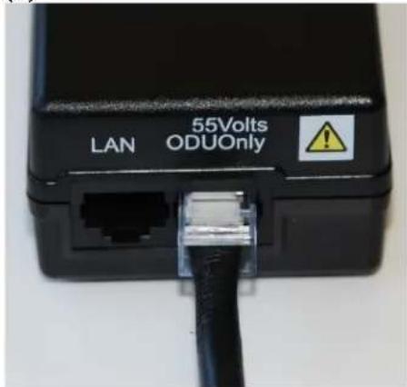
(b)
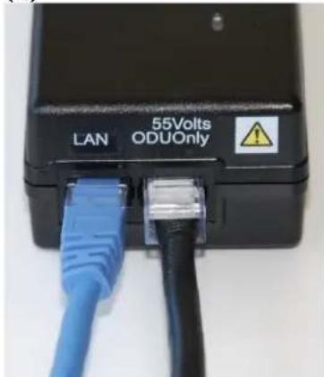
Installing CMM4

Note
For instructions on CMM3 (CMMmicro) or CMM4 installation, including the outdoor temperature range in which it is acceptable to install the unit, tools required, mounting and cabling instructions, and connectivity verification, please see the PMP Synchronization Solutions User Guide located on the Cambium website.
The Cluster Management Module 4 (CMM4) provides power, sync, and network connectivity for up to eight APs, backhauls, and Ethernet terrestrial feeds in a variety of configurations.
The CMM4 provides:
- Sync over Power over Ethernet and integrated surge suppression on the controller board for up to 8 APs or BHs. Both a custom 30 VDC power scheme and a custom 56 VDC power scheme are available. Neither is the same as the later IEEE Standard 802.3af, and neither is compatible with it.
- Managed switching using a hardened EtherWAN switch (1090CKHH models). The CMM4 ships with a 14-port EtherWAN switch and is also available without a switch. The CMM4 originally shipped with a 9-port EtherWAN switch.
- Surge suppression on the controller board for the incoming 30V DC and 56V DC power lines and GPS coax cable.
- Auto-negotiation on the Ethernet ports. Ports will auto-negotiate to match inputs that are either 100Base-T or 10Base-T, and either full duplex or half duplex, when the connected device is set to auto-negotiate. Alternatively, these parameters are settable.
- An always-on NTP (Network Time Protocol) server that can provide date and time to any radio that can reach the CMM's management IP address.
• CNUT can be used to upgrade the CMM-4 software.
450 Series and 450i Series can use the CMM4's EtherWan switch for their network connectivity.

Note
The 56 V of a CMM4 needs to go through the adapter cable (part number N000045L001A) as shown in Figure 40 on page 2-66.
A CMM4 56V power adapter cable can be prepared by swapping pins 5 and 7. See CMM4 56 V power adapter cable pinout on page 2-66 for power adapter cable pinout.
Supplemental installation information
This section contains detailed installation procedures that are not included in the above topics, such as how to strip cables, create grounding points and weatherproof connectors.
Stripping drop cable
When preparing the drop cable for connection to the 450 Platform Family ODU or LPU, use the following measurements:
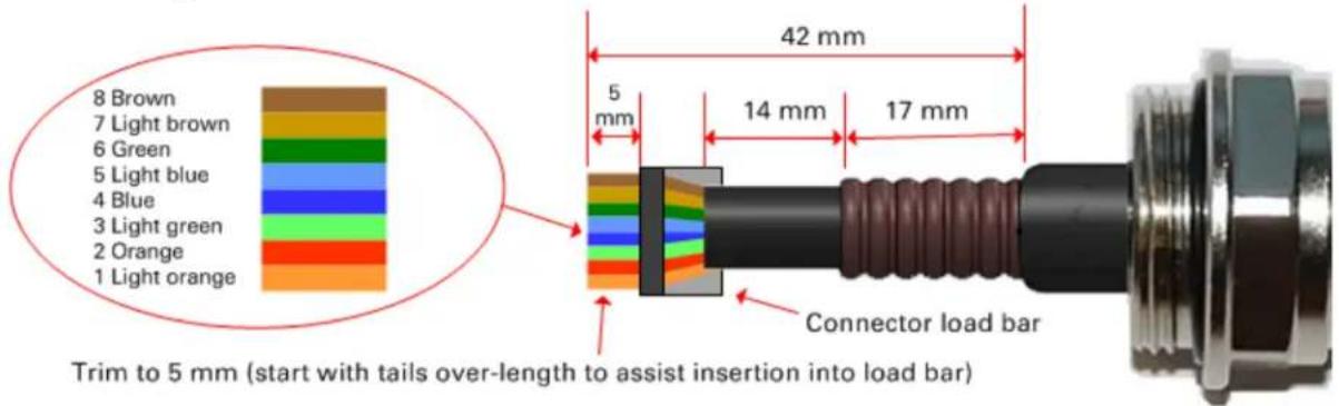
When preparing the drop cable for connection to the 450 Platform PSU (without a cable gland), use the following measurements:

Trim to 5 mm (start with tails over-length to assist insertion into load bar)
Creating a drop cable grounding point
Use this procedure to connect the screen of the main drop cable to the metal of the supporting structure using the cable grounding kit (Cambium part number 01010419001). To identify suitable grounding points, refer to Hazardous locations on page 3-16.
1 Remove 60 mm (2.5 inches) of the drop cable outer sheath.

natural_image
Close-up of a black cable with copper wire wrapped around its end, placed next to a ruler for scale (no text or symbols visible on the cable itself)2 Cut 38mm (1.5 inches) of rubber tape (self-amalgamating) and fit to the ground cable lug. Wrap the tape completely around the lug and cable.

natural_image
Close-up of a copper electrical terminal with two metal terminals and a black cable, no visible text or symbols.3 Fold the ground wire strap around the drop cable screen and fit cable ties.

natural_image
Close-up of a black electrical cable with copper wires and two copper connectors (no text or symbols visible)4 Tighten the cable ties with pliers. Cut the surplus from the cable ties.

natural_image
Close-up of a pair of metal pliers with copper fittings and two orange circular components, resting on a textured surface (no text or symbols visible)5 Cut a 38mm (1.5 inches) section of self -amalgamating tape and wrap it completely around the joint between the drop and ground cables.

natural_image
Close-up of a black electrical plug with exposed wires and insulation (no text or symbols visible)6 Use the remainder of the self-amalgamating tape to wrap the complete assembly. Press the tape edges together so that there are no gaps.

natural_image
Close-up of a black cable with exposed insulation and twisted insulation (no text or symbols visible)7 Wrap a layer of PVC tape from bottom to top, starting from 25 mm (1 inch) below and finishing 25 mm (1 inch) above the edge of the self-amalgamating tape, overlapping at half width.

natural_image
Close-up of a black plastic adhesive tape attached to a damaged cable, with no visible text or symbols.8 Repeat with a further four layers of PVC tape, always overlapping at half width. Wrap the layers in alternate directions (top to bottom, then bottom to top). The edges of each layer should be 25mm (1 inch) above (A) and 25 mm (1 inch) below (B) the previous layer.

natural_image
Close-up of a black cable with a tape measure attached, labeled A and B (no text or symbols on the object itself)9 Prepare the metal grounding point of the supporting structure to provide a good electrical contact with the grounding cable clamp. Remove paint, grease or dirt, if present. Apply anti-oxidant compound liberally between the two metals.
10 Clamp the bottom lug of the grounding cable to the supporting structure using site approved methods. Use a two-hole lug secured with fasteners in both holes. This provides better protection than a single-hole lug.
Attaching and weatherproofing an N type connector
The following procedure should be used to weatherproof the N type connectors fitted to the connectorized ODU (AP/SM/BH) and antenna. This procedure must be followed to ensure that there is no moisture ingress at the radio ports. Failure to properly seal N-type antenna connectors can result in poor link performance or complete loss of radio communication.

Note
Cambium recommends assembling the antenna, attach the ODU and cabling, and to seal the RF connections before installing the unit at the deployment site.

Note
N type connectors should be tightened using a torque wrench, set to 15 lb in or 1.7 Nm. If a torque wrench is not available, N type connectors may be finger tightened.
Use this procedure to weatherproof the N type connectors fitted to the connectorized ODU and external antenna (if recommended by the antenna manufacturer).
1 Ensure the connection is tight. A torque wrench should be used if available:

natural_image
Close-up of a metallic mechanical connector with threaded ends and a black shaft (no visible text or symbols)2 Wrap the connection with a layer of 19 mm (0.75 inch) PVC tape, starting 25 mm (1 inch) below the connector body. Overlap the tape to half-width and extend the wrapping to the body of the LPU. Avoid making creases or wrinkles:

natural_image
Close-up of a black rubber tape with a white label, attached to a mechanical lever (no visible text or symbols)3 Smooth the tape edges:

natural_image
Close-up of a hand holding a black plastic mechanical component with a metallic flange (no visible text or symbols)4 Cut a 125mm (5 inches) length of rubber tape (self-amalgamating):

natural_image
Close-up of a black rectangular object with a metallic connector attached, placed on a white surface (no text or symbols visible)5 Expand the width of the tape by stretching it so that it will wrap completely around the connector and cable:

natural_image
Close-up of a black mechanical tool with a curved blade and metallic base (no visible text or symbols)6 Press the tape edges together so that there are no gaps. The tape should extend 25 mm (1 inch) beyond the PVC tape:

natural_image
Close-up of a black cylindrical object with metallic end caps and a coiled handle (no visible text or symbols)7 Wrap a layer of 50 mm (2 inch) PVC tape from bottom to top, starting from 25 mm (1 inch) below the edge of the self-amalgamating tape, overlapping at half width.

natural_image
Close-up of a black cable with a black rubber tape attached, against a plain white background (no text or symbols visible)8 Repeat with a further four layers of 19 mm (0.75 inch) PVC tape, always overlapping at half width. Wrap the layers in alternate directions:
• Second layer: top to bottom.
• Third layer: bottom to top.
• Fourth layer: top to bottom.
• Fifth layer: bottom to top.
The bottom edge of each layer should be 25 mm (1 inch) below the previous layer.

natural_image
Close-up of a black-handled tool with a curved handle and a circular lens, isolated on white background (no text or symbols)9 Check the completed weatherproof connection:

natural_image
Close-up of a black cylindrical object with no visible text or symbols
Note
A video of this procedure can be found at:
https://www.youtube.com/watch?v=a-twPfCVq4A
Chapter 7: Configuration
This chapter describes how to use the web interface to configure the 450 Platform link. This chapter contains the following topics:
• Preparing for configuration on page 7-2
• Connecting to the unit on page 7-3
• Using the web interface on page 7-5
• Quick link setup on page 7-13
- Configuring IP and Ethernet interfaces on page 7-24
- Upgrading the software version and using CNUT on page 7-69
• General configuration on page 7-73
- Configuring Unit Settings page on page 7-96
- Setting up time and date on page 7-100
- Configuring synchronization on page 7-102
- Configuring security on page 7-104
- Configuring radio parameters on page 7-137
- Setting up SNMP agent on page 7-213
- Configuring syslog on page 7-222
- Configuring remote access on page 7-227
• Monitoring the Link on page 7-229
- Configuring quality of service on page 7-232
• Installation Color Code on page 7-258
• Zero Touch Configuration Using DHCP Option 66 on page 7-259
- Configuring Radio via config file on page 7-265
- Configuring a RADIUS server on page 7-273
Preparing for configuration
This section describes the checks to be performed before proceeding with unit configuration and antenna alignment.
Safety precautions
All national and local safety standards must be followed while configuring the units and aligning the antennas.

Warning
Ensure that personnel are not exposed to unsafe levels of RF energy. The units start to radiate RF energy as soon as they are powered up. Respect the safety standards defined in Compliance with safety standards on page 4-22, in particular the minimum separation distances.
Observe the following guidelines:
- Never work in front of the antenna when the ODU is powered.
- Always power down the PSU before connecting or disconnecting the drop cable from the PSU, ODU or LPU.
Regulatory compliance
All applicable radio regulations must be followed while configuring the units and aligning the antennas. For more information, refer to Compliance with radio regulations on page 4-39.

Caution
If the system designer has provided a list of channels to be barred for TDWR radar avoidance, the affected channels must be barred before the units are allowed to radiate on site, otherwise the regulations will be infringed.

Attention
Connecting to the unit
This section describes how to connect the unit to a management PC and power it up.
Configuring the management PC
Use this procedure to configure the local management PC to communicate with the 450 Platform ODU.
Procedure 9 Configuring the management PC
1 Select Properties for the Ethernet port. In Windows 7 this is found in Control Panel > Network and Internet > Network Connections > Local Area Connection.
2 Select Internet Protocol (TCP/IP):
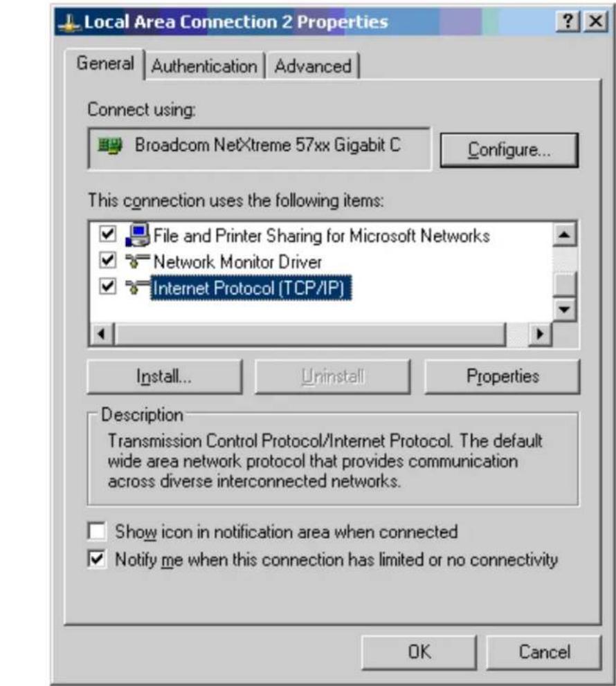
3 Click Properties.
4 Enter an IP address that is valid for the 169.254.X.X network, avoiding 169.254.0.0 and 169.254.1.1. A good example is 169.254.1.3:

5 Enter a subnet mask of 255.255.0.0. Leave the default gateway blank.
Connecting to the PC and powering up
Use this procedure to connect a management PC and power up the 450 platform ODU.
Procedure 10 Connecting to the PC and powering up
1 Check that the ODU and PSU are correctly connected.
2 Connect the PC Ethernet port to the LAN port of the PSU using a standard (not crossed) Ethernet cable.
3 Apply mains or battery power to the PSU. The green Power LED should illuminate continuously.
4 After about several seconds, check that the orange Ethernet LED starts with 10 slow flashes.
5 Check that the Ethernet LED then illuminates continuously.
Using the web interface
This section describes how to log into the 450 Platform Family web interface and use its menus.
Logging into the web interface
Use this procedure to log into the web interface as a system administrator.
Procedure 11 Logging into the web interface
1 Start the web browser from the management PC.
2 Type the IP address of the unit into the address bar. The factory default IP address is 169.254.1.1. Press ENTER. The web interface menu and System Summary page are displayed:
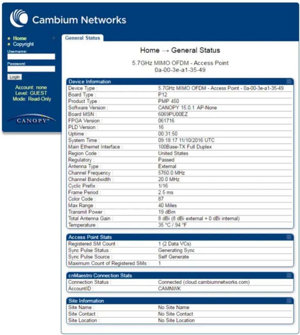
3 On left hand side of home page, the login information is displayed:

4 Enter Username (factory default username is admin) and Password (factory default password is admin) and click Login.
Web GUI
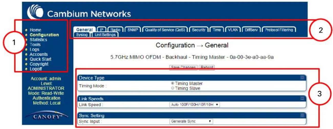
| Field Name | Description |
| Main Menu | Click an option in side navigation bar (area marked as “1”). Multiple options in sub-navigation bars appear |
| Menu Options | Click top sub-navigation bar to choose one configuration page (area marked as “2”) |
| Parameters | To configure the parameters (e.g. area marked as “3”) |
| Save Changes | Press "Save Changes" to confirm and save the changes |
| Reboot | To reboot the ODU |
Using the menu options
Use the menu navigation bar in the left panel to navigate to each web page. Some of the menu options are only displayed for specific system configurations. Use Table 113 to locate information about using each web page.
Table 113 Menu options and web pages
| Main menu | Menu options | Applicable module | Description |
| Home | |||
| General Status | All | Viewing General Status on page 9-2 | |
| Session Status | AP, BHM | Viewing Session Status on page 9-24 | |
| Event Log | All | Interpreting messages in the Event Log on page 9-34 | |
| Network Interface | AP, BHM | Viewing the Network Interface on page 9-37 | |
| Layer 2 Neighbors | All | Viewing the Layer 2 Neighbors on page 9-38 | |
| Configuration | |||
| General | All | General configuration on page 7-73 | |
| IP | All | Configuring IP and Ethernet interfaces on page 7-24 | |
| Radio | All | Configuring radio parameters on page 7-138 | |
| SNMP | All | Setting up SNMP agent on page 7-213 | |
| cnMaestro | All Configuring cnMaestroTM Connectivity on page 7-267 | ||
| Quality of Service (QoS) | All | Configuring quality of service on page 7-232 | |
| Security | All | Configuring security on page 7-104 | |
| Time | AP, BHM | Setting up time and date Time page of 450 Platform Family - AP/BHM on page 7-100 | |
| VLAN | All | VLAN configuration for PMP on page 7-46 VLAN configuration for PTP on page 7-57 | |
| DiffServ | All | IPv4 and IPv6 Prioritization on page 7-64 | |
| Protocol Filtering | All | Filtering protocols and ports on page 7-66 | |
| Syslog | All | Configuring syslog on page 7-222 | |
| Ping Watchdog | All | Configuring Ping Watchdog on page 7-317 | |
| Unit Setting | All | Configuring Unit Settings page on page 7-96 | |
| Statistics | |||
| Scheduler | All | Viewing the Scheduler statistics on page 9-39 | |
| AP, BHI Registration Failures | Viewing list of Registration Failures statistics on page 9-41 | ||
| Bridge Control Block | All | Interpreting Bridge Control Block statistics on page 9-23 | |
| All | Bridging Table | Interpreting Bridging Table statistics on page 9-43 | |
| Ethernet | All | Interpreting Ethernet statistics on page 9-44 | |
| All | Radio | Interpreting RF Control Block statistics on page 9-47 | |
| VLAN | All | Interpreting VLAN statistics on page 9-3 | |
| All | Data Channels | Interpreting Data Channels statistics on page 9-4 | |
| MIR/Burst | AP, SM | Interpreting MIR/Burst statistics on page 9-6 | |
| AP, BHM Throughput | Interpreting Throughput statistics on page 9-9 | ||
| Filter | SM | Interpreting Filter statistics on page 9-16 | |
| ARP | SM | Viewing ARP statistics on page 9-17 | |
| Overload | All | Interpreting Overload statistics on page 9-12 | |
| Syslog Statistics | All | Interpreting syslog statistics on page 9-29 | |
| Translation Table | SM | Interpreting Translation Table statistics on page 9-43 | |
| DHCP Relay | SM | Interpreting DHCP Relay statistics on page 9-14 | |
| NAT Stats | SM | Viewing NAT statistics on page 9-17 | |
| NAT DHCP | SM | Viewing NAT DHCP Statistics on page 9-19 | |
| AP | Pass Through Statistics | Interpreting Pass Through Statistics on page 9-26 | |
| Sync Status | AP | Interpreting Sync Status statistics on page 9-20 | |
| SM | PPPoE | Interpreting PPPoE Statistics for Customer Activities on page 9-21 | |
| SNMPv3 Statistics | All | Interpreting SNMPv3 Statistics on page 9-27 | |
| Frame Utilization | Interpreting Frame Utilization statistics on page 9-27 | ||
| Tools | |||
| Link Capacity Test | All | Using the Link Capacity Test tool on page 8-23 | |
| Spectrum Analyzer | All | Spectrum Analyzer tool on page 8-3 | |
| Remote Spectrum Analyzer | All | Remote Spectrum Analyzer tool on page 8-13 | |
| AP/BHM Evaluation | SM, BHS | Using AP Evaluation tool on page 8-32Using BHM Evaluation tool on page 8-36 | |
| Subscriber Configuration | AP | Using the Subscriber Configuration tool on page 8-45 | |
| OFDM Frame Calculator | AP, BHM | Using the OFDM Frame Calculator tool on page 8-40 | |
| BER results | SM | Using BER Results tool on page 8-53 | |
| Alignment Tool | SM, BHS | Using the Alignment Tool on page 8-16 | |
| Link Status | AP | Using the Link Status tool on page 8-46 | |
| Sessions | AP | Using the Sessions tool on page 8-54 | |
| Ping Test | All | Using the Ping Test tool on page 8-55 | |
| ● Logs | |||
| ● Accounts | |||
| Change User Setting | Changing a User Setting on page 7-106 | ||
| Add user | Adding a User for Access to a module on page 7-105 | ||
| Delete User | Deleting a User from Access to a module on page 7-106 | ||
| User | Users account on page 7-107 | ||
| ● Quick Start | |||
| Quick Start | AP, BHM | Quick link setup on page 7-13 | |
| Region Settings | AP, BHM | Quick link setup on page 7-13 | |
| Radio Carrier Frequency | AP, BHM | Quick link setup on page 7-13 | |
| Synchronization | AP, BHM | Quick link setup on page 7-13 | |
| LAN IP Address | AP, BHM | Quick link setup on page 7-13 | |
| Review and Save Configuration | AP, BHM | Quick link setup on page 7-13 | |
| ● PDA | |||
| Quick Status | SM | The PDA web-page includes 320 x 240 pixel formatted displays of information important to installation and alignment for installers using legacy PDA devices. All device web pages are compatible with touch devices such as smart phones and tablets. | |
| Spectrum Results (PDA) | SM | ||
| Information | SM | ||
| BHM Evaluation | SM | ||
| AIM | SM | ||
| ● Copyright | |||
| Copyright Notices | All | The Copyright web-page displays pertinent device copyright information. | |
| Logoff | All | ||
Quick link setup
This section describes how to use the Quick Start Wizard to complete the essential system configuration tasks that must be performed on a PMP/PTP configuration.

Note
If the IP address of the AP or BHM is not known, See Radio recovery mode on page 1-26.
Initiating Quick Start Wizard
Applicable products PMP:

AP
PTP:

BHM
To start with Quick Start Wizard: after logging into the web management interface click the Quick Start button on the left side of main menu bar. The AP/BHM responds by opening the Quick Start page.
Figure 127 Disarm Installation page (top and bottom of page shown)
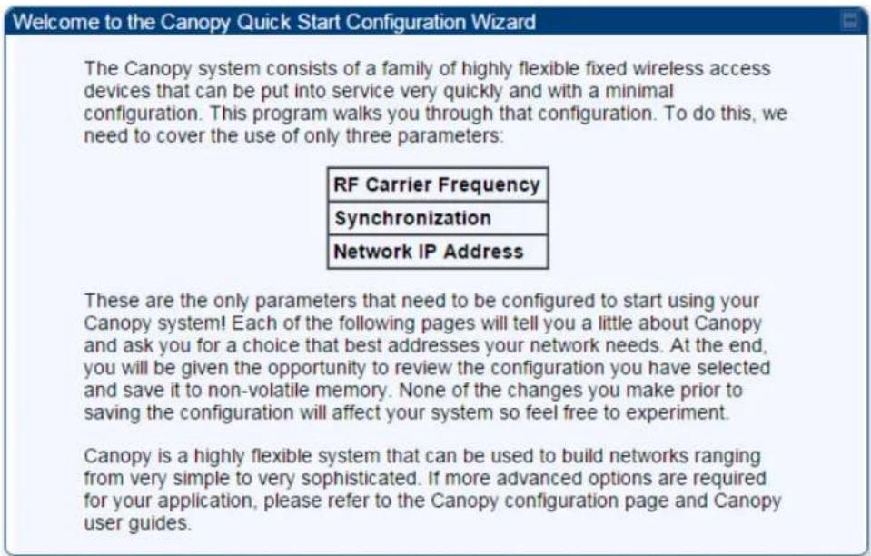
Quick Start is a wizard that helps you to perform a basic configuration that places an AP/BHM into service. Only the following parameters must be configured:
- Region Code
• RF Carrier Frequency - Synchronization
• LAN (Network) IP Address
In each Quick Start page, you can
- specify the settings to satisfy the requirements of the network.
• review the configuration selected.
• save the configuration to non-volatile memory.
Procedure 12 Quick start wizard
1 At the bottom of the Quick Start tab, click the Go To Next Page button.
2 From the pull-down menu, select the region in which the AP will operate.
Figure 128 Regional Settings tab of AP/BHM


3 Click the Go To Next Page button.
4 From the pull-down menu, select a frequency for the test.
Figure 129 Radio Carrier Frequency tab of AP/BHM


5 Click the Go To Next Page button.
6 At the bottom of this tab, select Generate Sync Signal.
Figure 130 Synchronization tab of AP/BHM


7 Click the Go To Next Page button.
8 At the bottom of the IP address configuration tab, either
- specify an IP Address, a Subnet Mask, and a Gateway IP Address for management of the AP and leave the DHCP state set to Disabled.
- set the DHCP state to Enabled to have the IP address, subnet mask, and gateway IP address automatically configured by a domain name server (DNS).
Figure 131 LAN IP Address tab of the AP/BHM

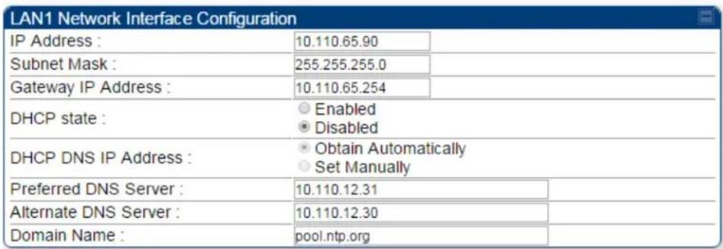
<=Go To Previous Page Go To Next Page=>

Note
Cambium encourages you to experiment with the interface. Unless you save a configuration and reboot the AP after you save the configuration, none of the changes are affected.
9 Click the Go To Next Page => button.
10 Ensure that the initial parameters for the AP are set as you intended.
Figure 132 Review and Save Configuration tab of the AP/BHM





<=Go To Previous Page
Save Changes
Reboot
11 Click the Save Changes button.
12 Click the Reboot button.
RESULT: The AP responds with the message Reboot Has Been Initiated...
13 Wait until the indicator LEDs are not red.
14 Trigger your browser to refresh the page until the AP redisplays the General Status tab.
15 Wait until the red indicator LEDs are not lit.
Configuring time settings
Applicable products PMP:

AP
PTP:

BHM
To proceed with the test setup, click the Configuration link on the left side of the General Status page. When the AP responds by opening the Configuration page to the General page, click the Time tab.
Figure 133 Time tab of the AP/BHM




To have each log in the AP/BHM correlated to a meaningful time and date, either a reliable network element must pass time and date to the AP/BHM or you must set the time and date whenever a power cycle of the AP/BHM has occurred. A network element passes time and date in any of the following scenarios:
- A connected CMM4 passes time and date (GPS time and date, if received).
• A separate NTP server is addressable from the AP/BHM.
If the AP/BHM should obtain time and date from a CMM4, or a separate NTP server, enter the IP address of the CMM4 or NTP server on this tab. To force the AP/BHM to obtain time and date before the first (or next) 15-minute interval query of the NTP server, click Get Time through NTP.
If you enter a time and date, the format for entry is
Figure 134 Time and date entry formats
Time:

Date:
where
hh represents the two-digit hour in the range 00 to 24
mm represents the two-digit minute
ss represents the two-digit second
MM represents the two-digit month
dd represents the two-digit day
yyyy represents the four-digit year
Proceed with the time setup as follows.
Procedure 13 Entering AP/BHM time setup information
1 Enter the appropriate information in the format shown above.
2 Then click the Set Time and Date button.

Note
The time displayed at the top of this page is static unless your browser is set to automatically refresh
Powering the SM/BHS for test
Procedure 14 Powering the SM/BHS for test
1 In one hand, securely hold the top (larger shell) of the SM/BHS. With the other hand, depress the lever in the back of the base cover (smaller shell). Remove the base cover.
2 Plug one end of a CAT 5 Ethernet cable into the SM PSU port
3 Plug the other end of the Ethernet cable into the jack in the pig tail that hangs from the power supply
4 Roughly aim the SM/BHS toward the AP/BHM
5 Plug the power supply into an electrical outlet

Warning
From this point until you remove power from the AP/BHM, stay at least as far from the AP/BHM as the minimum separation distance specified in Calculated distances and power compliance margins.
6 Repeat the foregoing steps for each SM/BHS that you wish to include in the test.
Viewing the Session Status of the AP/BHM to determine test registration
Once the SMs/BHS under test are powered on, return to the computing device to determine if the SM/BHS units have registered to the AP/BHM.

Note
In order for accurate power level readings to be displayed, traffic must be present on the radio link.
The Session Status tab provides information about each SM/BHS that has registered to the AP/BHM. This information is useful for managing and troubleshooting a system.
All information that you have entered in the Site Name field of the SM/BHS displays in the Session Status tab of the linked AP/BHM.
The Session Status tab also includes the current active values on each SM( or BHS) (LUID) for MIR, and VLAN, as well as the source of these values (representing the SM/BHS itself,
Authentication Server, or the AP/BHM and cap, if any—for example, APCAP as shown above)..
As an SM/BHS registers to the AP/BHM, the configuration source that this page displays for the associated LUID may change. After registration, however, the displayed source is stable and can be trusted.
Idle subscribers may be included or removed from the session status display by enabling or disabling, respectively, the Show Idle Sessions parameter. Enabling or disabling this parameter only affects the GUI display of subscribers, not the registration status.
The SessionStatus.xml hyperlink allows user to export session status page from web management interface of AP/BHM. The session status page will be exported in xml file.
Procedure 15 Viewing the AP Session Status page
1 On the AP web management GUI, navigate to Home, Session Status:
Figure 135 Session Status tab of AP
![General Status Session Status Remote Subscribers Event Log Network Interface Layer 2 Neighbors Home → Session Status 5.4GHz MIMO OFDM - Access Point - 0a-00-3e-a1-35-75 Session Status Configuration Show Idle Sessions : Enabled Disabled Session List Tools Last Session Counter Reset : None Reset Session Counters Last Time Idle SMs Removed : None Remove Idle SMs Session Status List Data : SessionStatus.xml Device Session Power Configuration Subscriber Hardware Software Version FPGA Version LUID: 002 - [0a-00-3e-a0-a0-66] No Site Name PMP 450 CANOPY 14.1.1 110615 (DES, Sched, US/ETSI) P](/content/2026/05/943724/images/81b3b44da924a6089cd6618d227cd04e90d92179cb55503ca2ff60358af0088c.jpg)

Note
Session status page for BHM is same as AP.
2 Verify that for each SM (or BHS) MAC address (printed on the SM/BHS housing) the AP/BHM has established a registered session by verifying the "State" status of each entry.
The Session Status page of the AP/BHM is explained in Table 114.
Table 114 Session Status Attributes - AP
| Session Status Configuration | |
| Show Idle Sessions : | EnabledDisabled |
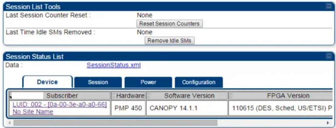 | |
| Attribute | Meaning |
| Show Idle Sessions | Idle subscribers may be included or removed from the session status display by enabling or disabling, respectively, the Show Idle Sessions parameter. Enabling or disabling this parameter only affects the GUI display of subscribers, not the registration status. |
| Last Session Counter Reset | This field displays date and time stamp of last session counter reset. |
| Last Time Idle SMs Removed | This field displays date and time stamp of last Idle SMs Removed. On click of “Remove Idle SMs” button, all the SMs which are in Idle state are flushed out. |
| Data | See Exporting Session Status page of AP/BHM on page 7-255 |
| Device tab | See Device tab on page 9-24 |
| Session tab | See Session tab on page 9-26 |
| Power tab | See Power tab on page 9-28 |
| Configuration tab See Configuration tab on page 9-30 | |
Configuring IP and Ethernet interfaces
This task consists of the following sections:
- Configuring the IP interface on page 7-25
• Auxiliary port on page 7-28
• NAT, DHCP Server, DHCP Client and DMZ on page 7-29
• IP interface with NAT disabled on page 7-34
• IP interface with NAT enabled on page
• NAT tab with NAT disabled on page 7-37
• NAT tab with NAT enabled on page 7-40
• NAT DNS Considerations on page 7-45
• DHCP - BHS on page 7-46
• VLAN configuration for PMP on page 7-46
• VLAN page of AP on page 7-49
• VLAN page of SM on page 7-52
• VLAN Membership tab of SM on page 7-57
• VLAN configuration for PTP on page 7-57
• NAT Port Mapping tab - SM on page 7-45
Configuring the IP interface
The IP interface allows users to connect to the 450 Platform Family web interface, either from a locally connected computer or from a management network.
| Applicable products | PMP: | ☑ | AP | ☑ | SM | PTP: | ☑ | BHM | ☑ | BMS |
To configure the IP interface, follow these instructions:
Procedure 16 Configuring the AP/BHM IP interface
1 Select menu option Configuration > IP. The LAN configuration page is displayed:
| LAN1 Network Interface Configuration | ||
| IP Address: | 169.254.1.1 | |
| Subnet Mask: | 255.255.0.0 | |
| Gateway IP Address: | 169.254.0.0 | |
| DHCP state: | EnabledDisabled | |
| DNS IP Address: | Obtain AutomaticallySet Manually | |
| Preferred DNS Server: | 0.0.0.0 | |
| Alternate DNS Server: | 0.0.0.0 | |
| Domain Name: | example.com | |
2 Update IP Address, Subnet Mask and Gateway IP Address to meet network requirements (as specified by the network administrator).
3 Review the other IP interface attributes and update them, if necessary (see Table 115 IP interface attributes).
4 Click Save. "Reboot Required" message is displayed:
| LAN1 Network Interface Configuration | |
| IP Address: | 189.254.1.2 |
| Subnet Mask: | 255.255.0.0 |
| Gateway IP Address: | 169.254.0.0 |
| DHCP state: | ○ Enabled○ Disabled |
| DNS IP Address: | ○ Obtain Automatically○ Set Manually |
| Preferred DNS Server: | 0.0.0.0 |
| Alternate DNS Server: | 0.0.0.0 |
| Domain Name: | example.com |
5 Click Reboot.
The IP page of AP/SM/BHM/BHS is explained in Table 115.
Table 115 IP interface attributes
| LAN1 Network Interface Configuration | |
| IP Address : | 10.110.245.135 |
| Subnet Mask : | 255.255.255.0 |
| Gateway IP Address : | 10.110.245.254 |
| DHCP state : | EnabledDisabled |
| DHCP DNS IP Address : | Obtain AutomaticallySet Manually |
| Preferred DNS Server : | 10.110.12.30 |
| Alternate DNS Server : | 10.110.12.31 |
| Domain Name : | example.com |
| Advanced LAN1 IP Configuration | |
| Default alternative LAN1 IP address : | EnabledDisabled |
| Aux Ethernet Port | |
| AUX Ethernet Port : | EnabledDisabled |
| AUX Ethernet Port PoE : | EnabledDisabledReset AUX PoE |
| LAN2 Network Interface Configuration (Radio Private Interface - Must end in .1) | |
| IP Address : | 192.168.101.1 |
| Attribute | Meaning |
| IP Address | Internet Protocol (IP) address. This address is used by family of Internet protocols to uniquely identify this unit on a network. |
| Subnet Mask | Defines the address range of the connected IP network. |
| Gateway IP Address | The IP address of a computer on the current network that acts as a gateway. A gateway acts as an entrance and exit to packets from and to other networks. |
| DHCP state | If Enabled is selected, the DHCP server automatically assigns the IP configuration (IP address, subnet mask, and gateway IP address) and the values of those individual parameters (above) are not used. The setting of this DHCP state parameter is also viewable (read only), in the Network Interface tab of the Home page. |
| DNS IP Address | Canopy devices allow for configuration of a preferred and alternate DNS server IP address either automatically or manually. Devices must set DNS server IP address manually when DHCP is disabled for themanagement interface of the device. DNS servers may be configured automatically from the DHCP response when DHCP is enabled for the management interface of the device. Optionally devices may be configured to set the DNS server IP address manually when DHCP is enabled for the management interface. The default DNS IP addresses are 0.0.0.0 when configured manually. |
| Preferred DNS Server | The first address used for DNS resolution. |
| Alternate DNS Server | If the Preferred DNS server cannot be reached, the Alternate DNS Server is used. |
| Domain Name | The operator's management domain name may be configured for DNS. The domain name configuration can be used for configuration of the servers in the operator's network. The default domain name is example.com, and is only used if configured as such. |
| Advanced LAN1 IP Configuration - Default alternate LAN1 IP address | Hardcoded default alternate IP address (169.254.1.1) that is available only when connected to the Ethernet port. When enabled, user can configure a second IP address for the bridge which is other than the hardcoded IP address (169.254.1.1). |
| AUX Ethernet Port - AUX Ethernet Port | Enabled: Data is enabled for Auxiliary portDisabled: Data is disabled for Auxiliary port |
| AUX Ethernet Port - AUX Ethernet Port PoE | Enabled: PoE out is enable for Auxiliary portDisabled: PoE out is disabled for Auxiliary port |
| LAN2 Network Interface Configuration (Radio Private Interface) - IP Address | It is recommended not to change this parameter from the default AP/BHM private IP address of 192.168.101.1. A /24 CIDR subnet is used to communicate with each of the SMs/BHS that are registered. The AP/BHM uses a combination of the private IP and the LUID (logical unit ID) of the SM/BHS.It is only displayed for AP and BHM. |
Table 116 SM/BHS private IP and LUID
| SM/BHS | LUID | Private IP |
| First SM/BHS registered | 2 | 192.168.101.2 |
| Second SM/BHS registered | 3 | 192.168.101.3 |
Auxiliary port
An additional Ethernet port labeled "Aux" for Auxiliary port is implemented for downstream traffic. This feature is supported only for PTP/PMP 450i ODUs.
To enable the Aux port, follow these instructions:
Procedure 17 Enabling Aux port interface
1 Select menu option Configuration > IP > Aux Network Interface tab.:

2 Click Enable button of Aux Ethernet Port parameter to enable Aux Ethernet port
3 Click Enable button of Aux Ethernet Port PoE parameter to enable Aux port PoE out.
4 Click Save. "Reboot Required" message is displayed.
5 Click Reboot.
Table 117 Aux port attributes
| Aux Network Interface | |
| Aux Ethernet Port : | EnabledDisabled |
| Aux Ethernet Port PoE : | EnabledDisabled |
| Attribute | Meaning |
| Aux Ethernet Port | Enabled: Data is enabled for Auxiliary portDisabled: Data is disabled for Auxiliary port |
| Aux Ethernet Port PoE | Enabled: PoE out is enable for Auxiliary portDisabled: PoE out is disabled for Auxiliary port |
By disabling this feature, the data at the Auxiliary port will be disabled.
NAT, DHCP Server, DHCP Client and DMZ
Applicable products
PMP:
SM
The system provides NAT (Network Address Translation) for SMs in the following combinations of NAT and DHCP (Dynamic Host Configuration Protocol):
- NAT Disabled
- NAT with DHCP Client (DHCP selected as the Connection Type of the WAN interface) and DHCP Server
- NAT with DHCP Client(DHCP selected as the Connection Type of the WAN interface)
• NAT with DHCP Server - NAT without DHCP
NAT
NAT isolates devices connected to the Ethernet or wired side of a SM from being seen directly from the wireless side of the SM. With NAT enabled, the SM has an IP address for transport traffic (separate from its address for management), terminates transport traffic and allows you to assign a range of IP addresses to devices that are connected to the Ethernet or wired side of the SM.
In the Cambium system, NAT supports many protocols, including HTTP, ICMP (Internet Control Message Protocols), and FTP (File Transfer Protocol). For virtual private network (VPN) implementation, L2TP over IPSec (Level 2 Tunneling Protocol over IP Security) and PPTP (Point to Point Tunneling Protocol) are supported.

Note
When NAT is enabled, a reduction in throughput is introduced in the system (due to processing overhead).
DHCP
DHCP enables a device to be assigned a new IP address and TCP/IP parameters, including a default gateway, whenever the device reboots. Thus, DHCP reduces configuration time, conserves IP addresses, and allows modules to be moved to a different network within the Cambium system.
In conjunction with the NAT features, each SM provides the following:
- A DHCP server that assigns IP addresses to computers connected to the SM by Ethernet protocol.
- A DHCP client that receives an IP address for the SM from a network DHCP server.
DMZ
In conjunction with the NAT features, a DMZ (Demilitarized Zone) allows the allotment of one IP address behind the SM for a device to logically exist outside the firewall and receive network traffic. The first three octets of this IP address must be identical to the first three octets of the NAT private IP address.
- A DHCP server that assigns IP addresses to computers connected to the SM by Ethernet protocol.
• A DHCP client that receives an IP address for the SM from a network DHCP server.
NAT Disabled
The NAT Disabled implementation is illustrated in Figure 136.
Figure 136 NAT disabled implementation

flowchart
graph TD
    A["NAT Disabled - No NAT (set on SM NAT Configuration page)"] --> B["AP"]
    B --> C["Module Management (HTTP, FTP, Telnet, SNMP)"]
    C --> D["Lan1 (set on AP IP Config)"]
    D --> E["To Network"]
    F["SM"] --> G["Module Management (HTTP, FTP, Telnet, SNMP)"]
    G --> H["Lan2 - RF Private (set on AP IP Config)"]
    H --> I["Lan2 - RF Private (Built from Lan2 address on AP IP Config)"]
    I --> J["To Subscriber"]
    K["Public=Connected Local= Not Connected (set on SM IP Config)"] --> L["Mobile Management (HTTP, FTP, Telnet, SNMP)"]
    L --> M["Lan1 (set on SM IP Config)"]
    M --> N["To Subscriber"]
    O["Computer IP Address(es) (set manually on computer(s) or network-level DHCP)"] --> P["To Subscriber"]
NAT with DHCP Client and DHCP Server
The NAT with DHCP Client and DHCP server is illustrated in Figure 137.
Figure 137 NAT with DHCP client and DHCP server implementation

flowchart
graph TD
    A["NAT with DHCP Client and DHCP Server (set on SM NAT Configuration page)"] --> B["AP"]
    B --> C["Module Management (HTTP, FTP, Telnet, SNMP)"]
    C --> D["Lan1 (set on AP IP Config)"]
    D --> E["To Network"]
    F["SM"] --> G["Module Management (HTTP, FTP, Telnet, SNMP)"]
    G --> H["Lan2 - RF Private (set on AP IP Config)"]
    H --> I["LAN2 - RF Private (Built from Lan2 address AP IP Config)"]
    I --> J["RF Public (set on SM IP Config)"]
    J --> K["NAT Private (set on SM IP Config)"]
    K --> L["DHCP Client"]
    L --> M["NAT"]
    M --> N["DHCP Server"]
    N --> O["To Subscriber"]
    P["Computer IP address(es) (set by DHCP, except DMZ set manually)"] --> Q["DHCP Server Start Address (based off of NAT Private), Number to Lease, and DMZ (set on SM IP Config)"]
    Q --> R["IP Address (assigned by network DHCP server)"]
    R --> S["Interface Enable=Connected Interface Disable=Not Connected (set on SM IP Config)"]
NAT with DHCP Client
Figure 138 NAT with DHCP client implementation

flowchart
graph TD
    A["NAT with DHCP Client\n(set on SM NAT Configuration page)"] --> B["AP"]
    B --> C["Module Management\n(HTTP, FTP, TeNet, SNMP)"]
    C --> D["Lan1\n(set on AP IP Config)"]
    D --> E["SM"]
    E --> F["Module Management\n(HTTP, FTP, TeNet, SNMP)"]
    F --> G["Lan2 - RF Private\n(set on AP IP Config)"]
    G --> H["Interface Enable=Connected Interface Disable=Not Connected\n(set on SM IP Config)"]
    H --> I["IP Address (assigned by network DHCP server)"]
    I --> J["DHCP Client"]
    J --> K["NAT"]
    K --> L["DMZ (set on SM IP Config)"]
    L --> M["To Subscriber"]
    M --> N["Computer IP Address(es) (set manually on computer(s), built from NAT Private address)"]
    style A fill:#f9f,stroke:#333
    style B fill:#ccf,stroke:#333
    style E fill:#cfc,stroke:#333
    style J fill:#fcc,stroke:#333
    style K fill:#cff,stroke:#333
NAT with DHCP Server
Figure 139 NAT with DHCP server implementation

flowchart
graph TD
    A["NAT with DHCP Server (set on SM NAT Configuration page)"] --> B["AP"]
    B --> C["Module Management (HTTP, FTP, Telnet, SNMP)"]
    C --> D["Lan1 (set on AP IP Config)"]
    D --> E["To Network"]
    F["NAT Public (set on SM IP Config)"] --> G["SM"]
    G --> H["Module Management (HTTP, FTP, Telnet, SNMP)"]
    H --> I["RF Public (set on SM IP Config)"]
    I --> J["NAT Private (set on SM IP Config)"]
    J --> K["NAT"]
    K --> L["DHCP Server"]
    L --> M["Computer IP address(es) (set by DHCP, except DMZ set manually)"]
    N["LAN2 - RF Private (set on AP IP Config)"] --> O["Interface Enable=Connected Interface Disable= Not Connected (set on SM IP Config)"]
    P["LAN2 - RF Private (built from Lan2 address on AP IP Config)"] --> Q["Interface Enable=Connected Interface Disable= Not Connected (set on SM IP Config)"]
    R["NAT Private"] --> S["NAT"]
    T["NAT Public"] --> U["DHCP Server Start Address (based off of NAT Private), Number to Lease, and DMZ (set on SM IP Config)"]
    V["To Subscriber"] --> W["Computer IP address(es) (set by DHCP, except DMZ set manually)"]
NAT without DHCP
Figure 140 NAT without DHCP implementation

flowchart
graph TD
    A["AP"] --> B["Module Management (HTTP, FTP, Telnet, SNMP)"]
    B --> C["Lan1 (set on AP IP Config)"]
    C --> D["To Network"]
    E["SM"] --> F["Module Management (HTTP, FTP, Telnet, SNMP)"]
    F --> G["Lan2 - RF Private (set on AP IP Config)"]
    G --> H["Interface Enable=Connected Interface Disable= Not Connected (set on SM IP Config)"]
    H --> I["NAT Public (set on SM IP config)"]
    I --> J["NAT"]
    J --> K["DMZ (set on SM IP Config)"]
    K --> L["To Subscriber"]
    M["Computer IP Address(es) (set manually on computer(s), built from NAT Private address)"] --> N["To Network"]
NAT and VPNs
VPN technology provides the benefits of a private network during communication over a public network. One typical use of a VPN is to connect employees remotely (who are at home or in a different city), with their corporate network through a public Internet. Any of several VPN implementation schemes is possible. By design, NAT translates or changes addresses, and thus interferes with a VPN that is not specifically supported by a given NAT implementation.
With NAT enabled, SM supports L2TP over IPSec (Level 2 Tunneling Protocol over IP Security) VPNs and PPTP (Point to Point Tunneling Protocol) VPNs. With NAT disabled, SM supports all types of VPNs.
IP interface with NAT disabled - SM
The IP page of SM with NAT disabled is explained in Table 118.
Table 118 IP attributes - SM with NAT disabled
| LAN1 Network Interface Configuration | ||
| IP Address: | 10.120.216.15 | |
| Network Accessibility: | ● Public○ Local | |
| Subnet Mask: | 265.265.255.0 | |
| Gateway IP Address: | 10.120.216.254 | |
| DHCP state: | ○ Enabled○ Disabled | |
| DHCP DNS IP Address: | ○ Obtain Automatically○ Set Manually | |
| Preferred DNS Server: | 0.0.0.0 | |
| Alternate DNS Server: | 0.0.0.0 | |
| Domain Name: | example.com | |
| Attribute | Meaning | |
| IP Address | Enter the non-routable IP address to associate with the Ethernet connection on this SM. (The default IP address from the factory is 169.254.1.1.) If you forget this parameter, you must both:• physically access the module.• use recovery mode to access the module configuration parameters at 169.254.1.1. See Radio recovery mode on page 1-26 | |
 | NoteNote or print the IP settings from this page. Ensure that you can readily associate these IP settings both with the module and with the other data that you store about the module. | |
| Network Accessibility | Specify whether the IP address of the SM must be visible to only a device connected to the SM by Ethernet (Local) or be visible to the AP/BHM as well (Public). | |
| Subnet Mask | Enter an appropriate subnet mask for the SM to communicate on the network. The default subnet mask is 255.255.0.0. | |
| Gateway IP Address | Enter the appropriate gateway for the SM to communicate with the network. The default gateway is 169.254.0.0. | |
| DHCP state | If you select Enabled, the DHCP server automatically assigns the IP configuration (IP address, subnet mask, and gateway IP address) and the values of those individual parameters (above) are not used. The setting of this DHCP state parameter is also viewable, but not settable, in the Network Interface tab of the Home page. | |
| In this tab, DHCP State is settable only if the Network Accessibility parameter in the IP tab is set to Public. This parameter is also settable in the NAT tab of the Configuration web page, but only when NAT is enabled.If the DHCP state parameter is set to Enabled in the Configuration > IP sub-menu of the SM/BHS, do not check the BootpClient option for Packet Filter Types in its Protocol Filtering tab, because doing so can block the DHCP request. (Filters apply to all packets that leave the SM via its RF interface, including those that the SM itself generates.) If you want to keep DHCP enabled and avoid the blocking scenario, select the Bootp Server option instead. This will result in responses being appropriately filtered and discarded. | ||
| DHCP DNS IP Address | Canopy devices allow for configuration of a preferred and alternate DNS server IP address either automatically or manually. Devices must set DNS server IP address manually when DHCP is disabled for the management interface of the device. DNS servers may be configured automatically from the DHCP response when DHCP is enabled for the management interface of the device. Optionally devices may be configured to set the DNS server IP address manually when DHCP is enabled for the management interface. The default DNS IP addresses are 0.0.0.0 when configured manually. | |
| Preferred DNS Server | The first DNS server used for DNS resolution. | |
| Alternate DNS Server | The second DNS server used for DNS resolution. | |
| Domain Name | The operator's management domain name may be configured for DNS. The domain name configuration can be used for configuration of the servers in the operator's network. The default domain name is example.com, and is only used if configured as such. | |
IP interface with NAT enabled - SM
The IP page of SM with NAT enabled is explained in Table 119.
Table 119 IP attributes - SM with NAT enabled
| NAT Network Interface Configuration | |
| IP Address: | 169.254.1.1 |
| Subnet Mask: | 255.255.255.0 |
| Attribute | Meaning |
| IP Address | Assign an IP address for SM/BHS management through Ethernet access to the SM/BHS. Set only the first three bytes. The last byte is permanently set to 1. This address becomes the base for the range of DHCP-assigned addresses. |
| Subnet Mask | Assign a subnet mask of 255.255.255.0 or a more restrictive subnet mask. Set only the last byte of this subnet mask. Each of the first three bytes is permanently set to 255. |
NAT tab with NAT disabled - SM
The NAT tab of SM with NAT disabled is explained in Table 120.
Table 120 NAT attributes - SM with NAT disabled
| NAT Enable | |
| NAT Enable/Disable: | EnabledDisabled |
| Save Changes | |
| WAN Interface | |
| Connection Type: | DHCP |
| IP Address: | 0.0.0.0 |
| Subnet Mask: | 255.255.255.0 |
| Gateway IP Address: | 0.0.0.0 |
| Reply to Ping on WAN Interface: | EnabledDisabled |
| LAN Interface | |
| IP Address: | 10.120.216.19 |
| Subnet Mask: | 255.255.255.xxx |
| DMZ Enable: | EnabledDisabled |
| DMZ IP Address: | xxx xxx xxx 62 |
| LAN DHCP Server | |
| DHCP Server Enable/Disable: | EnabledDisabled |
| DHCP Server Lease Timeout: | 30 Days (Range : 1 — 30) |
| DHCP Start IP: | xxx xxx xxx 2 |
| Number of IP's to Lease: | 50 |
| DNS Server Proxy: | EnabledDisabled |
| DNS IP Address: | Obtain Automatically (From WAN DHCP or PPPoE)Set Manually |
| Preferred DNS IP Address: | 0.0.0.0 |
| Alternate DNS IP Address: | 0.0.0.0 |
| Remote Configuration Interface | |
| Remote Management Interface: | Disable |
| Connection Type: | DHCPStatic IP |
| IP Address: | 0.0.0.0 |
| Subnet Mask: | 255.255.255.0 |
| Gateway IP Address: | 0.0.0.0 |
| DHCP DNS IP Address: | Obtain AutomaticallySet Manually |
| Preferred DNS Server: | 0.0.0.0 |
| Alternate DNS Server: | 0.0.0.0 |
| Domain Name: | example.com |
| NAT Protocol Parameters | |
| ARP Cache Timeout: | 20 Minutes (Range : 1 — 30) |
| TCP Session Garbage Timeout: | 120 Minutes (Range : 4 — 1440) |
| UDP Session Garbage Timeout: | 4 Minutes (Range : 1 — 1440) |
| Translation Table Size: | 2048 Translations (Range : 1024 — 8192) |
| Attribute | Meaning |
| NAT Enable/Disable | This parameter enables or disables the Network Address Translation (NAT) feature for the SM. NAT isolates devices connected to the Ethernet or wired side of a SM from being seen directly from the wireless side of the SM. With NAT enabled, the SM has an IP address for transport traffic separate from its address for management, terminates transport traffic, and allows you to assign a range of IP addresses to devices that are connected to the Ethernet or wired side of the SM.When NAT is enabled, VLANs are not supported on the wired side of that SM. You can enable NAT in SMs within a sector where VLAN is enabled in the AP/BHM, but this may constrain network design. |
| IP Address | This field displays the IP address for the SM. DHCP Server will not automatically assign this address when NAT is disabled. |
| Subnet Mask | This field displays the subnet mask for the SM. DHCP Server will not automatically assign this address when NAT is disabled. |
| Gateway IP Address | This field displays the gateway IP address for the SM. DHCP Server will not automatically assign this address when NAT is disabled. |
| ARP Cache Timeout | If a router upstream has an ARP cache of longer duration (as some use 30 minutes), enter a value of longer duration than the router ARP cache. The default value of this field is 20 minutes. |
| TCP Session Garbage Timeout | Where a large network exists behind the SM, you can set this parameter to lower than the default value of 120 minutes. This action makes additional resources available for greater traffic than the default value accommodates. |
| UDP Session Garbage Timeout | You may adjust this parameter in the range of 1 to 1440 minutes, based on network performance. The default value of this parameter is 4 minutes. |
| Translation Table Size | Total number of minutes that have elapsed since the last packet transfer between the connected device and the SM/BHS. |

Note
When NAT is disabled, the following parameters are not required to be configurable:
WAN Inter face > Connection Type, IP Address, Subnet Mask, Gateway IP address LAN Interface > IP Address
LAN DHCP Server > DHCP Server Enable/Disable, DHCP Server Lease Timeout, Number of IP's to Lease, DNS Server Proxy, DNS IP Address, Preferred DNS IP address, Alternate DNS IP address
Remote Management Interface > Remote Management Interface, IP address, Subnet Mask, DHCP DNS IP Address, Preferred DNS Server, Alternate DNS Server, Domain Name
NAT Protocol Parameters > ARP Cache Timeout, TCP Session Garbage Timeout, UDP Session Garbage Timeout, Translation Table Size
NAT tab with NAT enabled - SM
The NAT tab of SM with NAT enabled is explained in Table 121.
Table 121 NAT attributes - SM with NAT enabled
| NAT Enable | ||
| NAT Enable/Disable: | EnabledDisabled | |
| Save Changes | ||
| WAN Interface | ||
| Connection Type: | DHCP | |
| IP Address: | 0.0.0.0 | |
| Subnet Mask: | 255.255.255.0 | |
| Gateway IP Address: | 0.0.0.0 | |
| Reply to Ping on WAN Interface: | EnabledDisabled | |
| LAN Interface | ||
| IP Address: | 169.254.1.1 | |
| Subnet Mask: | 255.255.255.0 | |
| DMZ Enable: | EnabledDisabled | |
| DMZ IP Address: | 169.254.1.52 | |
| LAN DHCP Server | ||
| DHCP Server Enable/Disable: | EnabledDisabled | |
| DHCP Server Lease Timeout: | 30 Days (Range: 1—30) | |
| DHCP Start IP: | 169.254.1.2 | |
| Number of IPs to Lease: | 50 | |
| DNS Server Proxy: | EnabledDisabled | |
| DNS IP Address: | Obtain Automatically (From WAN DHCP or PPPoE)Set Manually | |
| Preferred DNS IP Address: | 0.0.0.0 | |
| Alternate DNS IP Address: | 0.0.0.0 | |
| Remote Configuration Interface | ||
| Remote Management Interface: | Enable (Standalone Config) | |
| Connection Type: | DHCPStatic IP | |
| IP Address: | 169.254.1.2 | |
| Subnet Mask: | 255.255.0.0 | |
| Gateway IP Address: | 169.254.0.0 | |
| DHCP DNS IP Address: | Obtain AutomaticallySet Manually | |
| Preferred DNS Server: | 0.0.0.0 | |
| Alternate DNS Server: | 0.0.0.0 | |
| Domain Name: | example.com | |
| NAT Protocol Parameters | ||
| ARP Cache Timeout: | 20 Minutes (Range: 1—30) | |
| TCP Session Garbage Timeout: | 120 Minutes (Range: 4—1440) | |
| UDP Session Garbage Timeout: | 4 Minutes (Range: 1—1440) | |
| Attribute | Meaning | |
| NAT Enable/Disable | This parameter enables or disabled the Network Address Translation (NAT) feature for the SM. NAT isolates devices connected to the Ethernet or wired side of a SM from being seen directly from the wireless side of the SM. With NAT enabled, the SM has an IP address for transport traffic separate from its address for management, terminates transport traffic, and allows you to assign a range of IP addresses to devices that are connected to the Ethernet or wired side of the SM.When NAT is enabled, VLANs are not supported on the wired side of that SM. You can enable NAT in SMs within a sector where VLAN is enabled in the AP, but this may constrain network design. | |
| WAN Interface | The WAN interface is the RF-side address for transport traffic. | |
| Connection Type | This parameter may be set toStatic IP—when this is the selection, all three parameters (IP Address, Subnet Mask, and Gateway IP Address) must be properly populated.DHCP—when this is the selection, the information from the DHCP server configures the interface.PPPoE—when this is the selection, the information from the PPPoE server configures the interface. | |
| Subnet Mask | If Static IP is set as the Connection Type of the WAN interface, then this parameter configures the subnet mask of the SM for RF transport traffic. | |
| Gateway IP Address | If Static IP is set as the Connection Type of the WAN interface, then this parameter configures the gateway IP address for the SM for RF transport traffic. | |
| Reply to Ping on WAN Interface | By default, the radio interface does not respond to pings. If you use a management system (such as WM) that will occasionally ping the SM, set this parameter to Enabled. | |
| LAN Interface | The LAN interface is both the management access through the Ethernet port and the Ethernet-side address for transport traffic. When NAT is enabled, this interface is redundantly shown as the NAT Network Interface Configuration on the IP tab of the Configuration web page in the SM. | |
| IP Address | Assign an IP address for SM/BHS management through Ethernet access to the SM. This address becomes the base for the range of DHCP-assigned addresses. | |
| Subnet Mask | Assign a subnet mask of 255.255.255.0 or a more restrictive subnet mask. Set only the last byte of this subnet mask. Each of the first three bytes is permanently set to 255. | |
| DMZ Enable | Either enable or disable DMZ for this SM/BHS. | |
| DMZ IP Address | If you enable DMZ in the parameter above, set the last byte of the DMZ host IP address to use for this SM when DMZ is enabled. Only one such address is allowed. The first three bytes are identical to those of the NAT private IP address. Ensure that the device that receives network traffic behind this SM is assigned this address. The system provides a warning if you enter an address within the range that DHCP can assign. | |
| DHCP Server | This is the server (in the SM) that provides an IP address to the device connected to the Ethernet port of the SM. | |
| DHCP Server Enable/Disable | Select either Enabled or Disabled.Enable to:Allow this SM to assign IP addresses, subnet masks, and gateway IP addresses to attached devices.Assign a start address for DHCP.Designate how many IP addresses may be temporarily used (leased). Disable to:Restrict SM/BHS from assigning addresses to attached devices. | |
| DHCP Server Lease Timeout | Based on network performance, enter the number of days between when the DHCP server assigns an IP address and when that address expires. The range of values for this parameter is 1 to 30 days. The default value is 30 days. | |
| DHCP Start IP | If you enable DHCP Server below, set the last byte of the starting IP address that the DHCP server assigns. The first three bytes are identical to those of the NAT private IP address. | |
| Number of IPs to Lease | Enter how many IP addresses the DHCP server is allowed to assign. The default value is 50 addresses. | |
| DNS Server Proxy | This parameter enables or disables advertisement of the SM/BHS as the DNS server. On initial boot up of a SM with the NAT WAN interface configured as DHCP or PPPoE, the SM module will not have DNS information immediately. With DNS Server Proxy disabled, the clients will renew their lease about every minute until the SM has the DNS information to give out. At this point the SM will go to the full configured lease time period which is 30 days by default. With DNS Server Proxy enabled, the SM will give out full term leases with its NAT LAN IP as the DNS server. | |
| DNS IP Address | Select either:Obtain Automatically to allow the system to set the IP address of the DNS serverorSet Manually to enable yourself to set both a preferred and an alternate DNS IP address. | |
| Preferred DNS IP Address | Enter the preferred DNS IP address to use when the DNS IP Address parameter is set to Set Manually. | |
| Alternate DNS IP Address | Enter the DNS IP address to use when the DNS IP Address parameter is set to Set Manually and no response is received from the preferred DNS IP address. | |
| Remote Management Interface | To offer greater flexibility in IP address management, the NAT-enabled SM's configured WAN Interface IP address may now be used as the device Remote Management Interface (unless the SM's PPPoE client is set to Enabled)Disable: When this interface is set to "Disable", the SM is not directly accessible by IP address. Management access is only possible through either the LAN (Ethernet) interface or a link from an AP web page into the WAN (RF-side) interface.Enable (Standalone Config): When this interface is set to "Enable (Standalone Config)", to manage the SM/BHS the device must be accessed by the IP addressing information provided in the Remote Configuration Interface section. | |
 | NoteWhen configuring PPPoE over the link, use this configuration option (PPPoE traffic is routed via the IP addressing specified in section Remote Configuration Interface). | |
| Enable (Use WAN Interface): When this interface is set to "Enable (Use WAN Interface)", the Remote Configuration Interface information is greyed out, and the SM is managed via the IP addressing specified in section WAN Interface). | ||
 | NoteWhen using this configuration, the ports defined in section Configuration, Port Configuration are consumed by the device. For example, if FTP Port is configured as 21 by the SM, an FTP server situated below the SM must use a port other than 21. This also applies to DMZ devices; any ports specified in section Configuration, Port Configuration will not be translated through the NAT, they are consumed by the device's network stack for management. | |
| Connection Type | This parameter can be set to:Static IP—when this is the selection, all three parameters (IP Address, Subnet Mask, and Gateway IP Address) must be properly populated.DHCP—when this is the selection, the information from the DHCP server configures the interface. | |
| IP Address | If Static IP is set as the Connection Type of the WAN interface, then this parameter configures the IP address of the SM for RF management traffic. | |
| Subnet Mask | If Static IP is set as the Connection Type of the WAN interface, then this parameter configures the subnet mask of the SM for RF management traffic. | |
| Gateway IP Address | If Static IP is set as the Connection Type of the WAN interface, then this parameter configures the gateway IP address for the SM for RF management traffic.Note or print the IP settings from this page. Ensure that you can readily associate these IP settings both with the module and with the other data that you store about the module. | |
| DHCP DNS IP Address | Select either:Obtain Automatically to allow the system to set the IP address of the DNS server.orSet Manually to enable yourself to set both a preferred and an alternate DNS IP address. | |
| Preferred DNS Server | Enter the preferred DNS IP address to use when the DNS IP Address parameter is set to Set Manually. | |
| Alternate DNS Server | Enter the DNS IP address to use when the DNS IP Address parameter is set to Set Manually and no response is received from the preferred DNS IP address. | |
| Domain Name | Domain Name to use for management DNS configuration. This domain name may be concatenated to DNS names used configured for the remote configuration interface. | |
| ARP Cache Timeout | If a router upstream has an ARP cache of longer duration (as some use 30 minutes), enter a value of longer duration than the router ARP cache. The default value of this field is 20 (minutes). | |
| TCP Session Garbage Timeout | Where a large network exists behind the SM, you can set this parameter to lower than the default value of 120 (minutes). This action makes additional resources available for greater traffic than the default value accommodates. | |
| UDP Session Garbage Timeout | You may adjust this parameter in the range of 1 to 1440 minutes, based on network performance. The default value of this parameter is 4 (minutes). | |
NAT DNS Considerations - SM
SM DNS behavior is different depending on the accessibility of the SM. When NAT is enabled the DNS configuration that is discussed in this document is tied to the RF Remote Configuration Interface, which must be enabled to utilize DNS Client functionality. Note that the WAN DNS settings when NAT is enabled are unchanged with the addition of the management DNS feature discussed in this document.
Table 122 SM DNS Options with NAT Enabled
| NAT Configuration | Management Interface Accessibility | DHCP Status | DNS Status |
| NAT Enabled | RF Remote Management Interface Disabled | N/A DNS Disabled | |
| RF Remote Management Interface Enabled | DHCP Disabled | DNS Static Configuration | |
| DHCP Enabled | DNS from DHCP or DNS Static Configuration | ||
The NAT Port Mapping tab of the SM is explained in Table 123.
Table 123 NAT Port Mapping attributes - SM
| Port Mapping Configuration | |||
| Port Map 1: | Port Number: 0 | Protocol: All Protocols IP: 0.0.0.0 | |
| Port Map 2: | Port Number: 0 | Protocol: All Protocols IP: 0.0.0.0 | |
| Port Map 3: | Port Number: 0 | Protocol: All Protocols IP: 0.0.0.0 | |
| Port Map 4: | Port Number: 0 | Protocol: All Protocols IP: 0.0.0.0 | |
| Port Map 5: | Port Number: 0 | Protocol: All Protocols IP: 0.0.0.0 | |
| Port Map 6: | Port Number: 0 | Protocol: All Protocols IP: 0.0.0.0 | |
| Port Map 7: | Port Number: 0 | Protocol: All Protocols IP: 0.0.0.0 | |
| Port Map 8: | Port Number: 0 | Protocol: All Protocols IP: 0.0.0.0 | |
| Port Map 9: | Port Number: 0 | Protocol: All Protocols IP: 0.0.0.0 | |
| Port Map 10: | Port Number: 0 | Protocol: All Protocols IP: 0.0.0.0 | |
| Attribute | Meaning |
| Port Map 1 to 10 | Separate parameters allow you to distinguish NAT ports from each other by assigning a unique combination of port number, protocol for traffic through the port, and IP address for access to the port |
DHCP - BHS
Applicable products
PTP: ☑ BHM
DHCP enables a device to be assigned a new IP address and TCP/IP parameters, including a default gateway, whenever the device reboots. Thus, DHCP reduces configuration time, conserves IP addresses, and allows modules to be moved to a different network within the Cambium system.
In conjunction with the NAT features, each BHS provides:
- A DHCP server that assigns IP addresses to computers connected to the BHS by Ethernet protocol.
- A DHCP client that receives an IP address for the BHS from a network DHCP server.
Reconnecting to the management PC
If the IP Address, Subnet Mask and Gateway IP Address of the unit have been updated to meet network requirements, then reconfigure the local management PC to use an IP address that is valid for the network. See Configuring the management PC on page 7-3.
Once the unit reboots, log in using the new IP address. See Logging into the web interface on page 7-5.
VLAN configuration for PMP
Applicable products
PMP: ☑ AP ☑ SM
VLAN Remarking
VLAN Remarking feature allows the user to change the VLAN ID and priority of both upstream and downstream packets at the Ethernet Interface. The remarking configuration is available for:
- VLAN ID re-marking
- 802.1p priority re-marking

Note
For Q-in-Q VLAN tagged frame, re-marking is performed on the outer tag.
VLAN ID Remarking
SM supports the ability to re-mark the VLAN ID on both upstream and downstream VLAN frames at the Ethernet interface. For instance, a configuration can be added to re-mark VLAN ID 'x' to VLAN ID 'y' as shown in Table 124. AP does not support VLAN ID remarking.
Table 124 VLAN Remarking Example
| VLAN frame direction | Remarking |
| Upstream | SM receives VLAN ID ‘x’ frame at the Ethernet interface, checks the configuration and re-marks to VLAN ID ‘y’. So VLAN ID ‘y’ frame comes out of AP’s Ethernet interface. When SM re-marks, a dynamic entry in VLAN membership table for ‘y’ is added to allow reception of VLAN ID ‘y’ downstream packet. |
| Downstream | AP receives VLAN ID ‘y’ frame at the Ethernet interface and sends to SM. SM accepts the frame as it has an entry in the membership table and re-marks to VLAN ID ‘x’. This reverse re- marking is necessary because the downstream devices do not know of re-marking and are expecting VLAN ‘x’ frames. This remarking is done just before sending the packet out on Ethernet interface. |
802.1P Remarking
AP/BHM and SM/BHS allow re-marking of 802.1p priority bits for the frames received at the Ethernet interface. Priority bits are not re-marked for the packets sent out of Ethernet interface (reverse direction).
Configuration must be added at SM/BHS for upstream frames and at AP/BHM for downstream frames.
VLAN Priority Bits configuration
VLAN Priority Bits Configuration feature allows the user to configure the three 802.1p bits upon assigning VLAN to an ingress packet. The priority bits configuration is available for:
- Default Port VID
- Provider VID
• MAC Address mapped Port VID
• Management VID
Default Port VID
This VID is used for untagged frames and will correspond to the Q-Tag for 802.1Q frames (if VLAN Port Type is Q), or the C-Tag for 802.1ad frames (if the VLAN Port Type is QinQ).
The priority bits used in the Q-tag/C-tag are configurable.
The configuration can be:
- Promote IPv4/IPv6 priority – The priority in the IP header is copied to the Q-tag/C-tag.
- Define priority – Specify the priority in the range of 0 to 7. This value is used as priority in the Q-tag/C-tag.
MAC Address Mapped VID
If a packet arrives at the SM/BHS that is sourced from a device whose MAC address is in the table, then the corresponding VID is used for that frame's Q-tag (Q port) or C-tag (QinQ port). The priority bits used in the Q-tag/C-tag are configurable similar to default port VID.
Provider VID
The provider VID is used for the S-tag. The priority bits used in the S-tag are configurable similar to default port VID. Provider VID has an extra priority configuration:
- Copy inner tag 802.1p priority – The priority in the C-tag is copied to the S-tag.
Management VID
This VID is used to communicate with AP/BHM and SM/BHS for management purposes. The priority bits used in the Q-tag are configurable similar to default port VID.
Use AP's Management VID for ICC connected SM
This feature allows the SM to use the AP's management VLAN ID when the SM is registered to the AP via ICC. This feature is useful for the customer who uses a different management VID for the SM and AP and Zero Touch feature is enabled for configuration. This parameter may be accessed via the Configuration > VLAN page on the AP's web management interface.
VLAN page of AP
The VLAN tab of the AP/BHM is explained in Table 125.
Table 125 AP/BHM VLAN tab attributes
| VLAN Configuration | |
| VLAN : | EnabledDisabled |
| Always use Local VLAN Config : | EnabledDisabled(NOTE: If you want to run spectrum analysis on this AP, enable this option to keep VLAN settings intact when booting as an SM.) |
| Allow Frame Types : | All Frames▼ |
| Dynamic Learning : | EnabledDisabled |
| VLAN Aging Timeout : | 25 Minutes (Range : 5 — 1440 Minutes) |
| Management VID (Range : 1 — 4094) : | 1 |
| QinQ EtherType : | 0x88a8▼ |
| Use AP's Management VID for ICC connected SM : | EnabledDisabled |
| Active Configuration |
| VLAN Not Active |
| VLAN Membership Configuration | ||
| VLAN Membership Table Configuration : | 1 | (Range : 1 — 4094) |
| Add Member | Remove Member | |
| VLAN Membership Table |
| Empty Set |
| VLAN 802.1p Remarking | ||
| Source VLAN : | 1 | (Range : 1 — 4094) |
| Remark Priority : | 0 | (Range : 0 — 7) |
| Add/Modify 802.1p Remarking | Remove 802.1p Remarking | |
| VLAN Remarking Table |
| Empty Set |
| Attribute | Meaning | |||
| VLAN | Specify whether VLAN functionality for the AP and all linked SMs must (Enabled) or may not (Disabled) be allowed. The default value is Disabled. | |||
| Always use Local VLAN Config | Enable this option before you reboot this AP as a SM to use it to perform spectrum analysis. Once the spectrum analysis completes, disable this option before you reboot the module as an AP, | |||
| Allow Frame Types | Select the type of arriving frames that the AP must tag, using the VID that is stored in the Untagged Ingress VID parameter. The default value is All Frames. | |||
| Dynamic Learning | Specify whether the AP must (Enabled) or not (Disabled) add the VLAN IDs (VIDs) of upstream frames to the VID table. (The AP passes frames with VIDs that are stored in the table both upstream and downstream.). The default value is Enabled. | |||
| VLAN Aging Timeout | Specify how long the AP must keep dynamically learned VIDs. The range of values is 5 to 1440 (minutes). The default value is 25 (minutes). | |||
 | NoteVIDs that you enter for the Management VID and VLAN Membership parameters do not time out. | |||
| Management VID Enter the VID that the operator wishes to use to communicate with the module manager. The range of values is 1 to 4095. The default value is 1. | ||||
| QinQ EtherType | Modules can be configured with 802.1ad Q-in-Q DVLAN (Double-VLAN) tagging which is a way for an operator to put an 802.1Q VLAN inside of an 802.1ad VLAN. A nested VLAN, which is the original 802.1Q tag and a new second 802.1ad tag, allows for bridging of VLAN traffic across a network and segregates the broadcast domains of 802.1Q VLANs. Q-in-Q can be used with PPPoE and/or NAT.The 802.1ad standard defines the S-VLAN as the Service Provider VLAN and the C-VLAN as the customer VLAN. The radio software does 2 layer Q-in-Q whereby the C-VLAN is the 802.1Q tag and the S-VLAN is the second layer Q tag as shown below:Table 126 Q-in-Q Ethernet frame | |||
| Ethernet Header | S-VLANEthType 0x88a8 | C-VLAN EthType 0x8100 | IP Data EthType 0x0800 | |
| The 802.1ad S-VLAN is the outer VLAN that is configurable on the Configuration > VLAN web page of the AP. The Q-in-Q EtherType parameter is configured with a default EtherType of 0x88a8 in addition to four alternate EtherTypes that can be configured to aid in interoperability with existing networks that use a different EtherType than the default.The C-VLAN is the inner VLAN tag, which is the same as 802.1Q. As a top-level concept, this operates on the outermost tag at any given time, either “pushing” a tag on or “popping” a tag off. This means packets will at most transition from an 802.1Q frame to an 801.ad frame (with a tag “pushed” on) or an untagged 802.1 frame (with the tag “popped” off. Similarly, for an 802.1ad frame, this can only transition from an 802.1ad frame to an 802.1Q frame (with the tag “popped” off) since the radio software only supports 2 levels of tags. | ||||
| Use AP’s Management VID for ICC connected SM | This field allows the SM to use the AP’s management VLAN ID when the SM is registered to the AP via ICC. | |||
| VLAN Not Active | When VLAN is enabled in the AP, the Active Configuration block provides the following details as read-only information in this tab. In the Cambium fixed wireless broadband IP network, each device of any type is automatically a permanent member of VID 1. This facilitates deployment of devices that have VLAN enabled with those that do not. | |||
| VLAN Membership Table Configuration | For each VLAN in which you want the AP to be a member, enter the VLAN ID and then click the Add Member button. Similarly, for any VLAN in which you want the AP to no longer be a member, enter the VLAN ID and then click the Remove Member button. | |||
| VLAN Membership table | This field lists the VLANs that an AP is a member of. As the user adds a number between 1 and 4094, this number is populated here. | |||
| Source VLAN (Range: 1-4094) | Enter the VID for which the operator wishes to remark the 802.1p priority for the downstream packets. The range of values is 1 to 4094. The default value is 1. | |||
| Remark Priority (Range 0-7) | This is the priority you can assign to the VLAN Tagged packet. Priority of 0 is the highest. | |||
| VLAN Remarking table | As the user enters a VLAN and a Remarking priority, this information is added in this table. | |||
VLAN page of SM
The VLAN tab of SM/BHS is explained in Table 127.
Table 127 SM VLAN attributes
| VLAN Configuration | ||||
| VLAN Port Type: | Q | |||
| Accept QinQ Frames: | EnabledDisabled | |||
| Allow Frame Types: | All Frames | |||
| Dynamic Learning: | EnabledDisabled | |||
| VLAN Aging Timeout: | 25 | Minutes (Range: 5 — 1440 Minutes) | ||
| Management VID: | 1 | (Range: 1 — 4094) | ||
| SM Management VID Pass-through: | DisableEnable(NOTE: If disabled, MVID traffic will not be allowed to or from the SM wired interface. Also, If Management VID is the same as a Port VID (Default or MAC-based), then this setting will be ignored and assumed to be Enabled.) | |||
| Default Port VID: | 1 | (Range: 1 — 4094) | ||
| Port VID MAC Address MappingMAC address of 0's indicates an unused entry.: | 00-00-00-00-00-00 | VID | 1 | (Range: 1 — 4094) |
| 00-00-00-00-00-00 | VID | 1 | (Range: 1 — 4094) | |
| 00-00-00-00-00-00 | VID | 1 | (Range: 1 — 4094) | |
| 00-00-00-00-00-00 | VID | 1 | (Range: 1 — 4094) | |
| 00-00-00-00-00-00 | VID | 1 | (Range: 1 — 4094) | |
| 00-00-00-00-00-00 | VID | 1 | (Range: 1 — 4094) | |
| 00-00-00-10-00-00 | VID | 1 | (Range: 1 — 4094) | |
| 00-00-00-00-00-00 | VID | 1 | (Range: 1 — 4094) | |
| 00-00-00-00-00-00 | VID | 1 | (Range: 1 — 4094 | |
| Provider VID: | 1 | (Range: 1 — 4094) | ||
| Active Configuration | |
| Default Port VID : 1 | |
| MAC Address VID Map: | |
| Management VID : 1 | |
| SM Management VID Passthrough : Enabled | |
| Dynamic Ageing Timeout : 25 | |
| Allow Learning : Yes | |
| Allow Frame Type : All Frame Types | |
| QinQ : Disabled | |
| QinQ EthType : 0x88a8 | |
| Allow QinQ Tagged Frames : No | |
| Current VID Member Set: | |
| VID Number Type Age | |
| 1 Permanent 0 |
| Attribute | Meaning | |
| VLAN Port Type | By default, this is Q, indicating that it is to operate in the existing manner. The other option is Q-in-Q, which indicates that it must be adding and removing the S-Tag, and adding a C-Tag if necessary for untagged packets. The VLAN Port type corresponds to the Ethernet port of the SM/BHS. Currently, the internal management interfaces will always operate as Q ports. | |
| Accept QinQ Frames | This option is valid for the Q-in-Q port so that the user may force blocking of existing 802.1ad Q-in-Q frames. This way, only untagged or single tagged packets will come in and out of the Ethernet interface. If a Q-in-Q frame is about ingress or egress the Ethernet interface and this is disabled, it is dropped and a filter entry will show up on the VLAN Statistics page as DVLAN Egress or DVLAN Ingress. | |
| Allow Frame Types | Select the type of arriving frames that the SM must tag, using the VID that is stored in the Untagged Ingress VID parameter. The default value is All Frames.Tagged Frames Only: The SM only tags incoming VLAN-tagged framesUntagged Frames Only: The SM will only tag incoming untagged frames | |
| Dynamic Learning | Specify whether the SM must (Enable) or not (Disable) add the VIDs of upstream frames (that enter the SM through the wired Ethernet interface) to the VID table. The default value is Enable. | |
| VLAN Aging Timeout | Specify how long the SM/BHS must keep dynamically learned VIDs. The range of values is 5 to 1440 (minutes). The default value is 25 (minutes). | |
 | NoteVIDs that you enter for the Untagged Ingress VID and Management VID parameters do not time out. | |
| Management VID | Enter the VID that the SM/BHS must share with the AP/BHM. The range of values is 1 to 4095. The default value is 1. | |
| SM Management VID Pass-through | Specify whether to allow the SM/BHS (Enabled) or the AP/RADIUS (Disabled) to control the VLAN settings of this SM. The default value is Enabled.When VLAN is enabled in the AP to whom this SM is registered, the Active Configuration block provides the following details as read-only information in this tab. In the Cambium fixed wireless broadband IP network, each device of any type is automatically a permanent member of VID 1. This facilitates deployment of devices that have VLAN enabled with those that do not.If disabled, MVID traffic is not allowed to or from the SM wired interface. Also, if Management VID is the same as a Port VID (Default or MAC-based), then this setting is ignored and assumed to be Enabled. | |
| Default Port VID | This is the VID that is used for untagged frames and will correspond to the Q-Tag for 802.1Q frames (if VLAN Port Type is Q), or the C-Tag for 802.1ad frames (if the VLAN Port Type is Q-in- Q). | |
| Port VID MAC Address Mapping | These parameters allow operators to place specific devices onto different VLANs (802.1Q tag or 802.1ad C-tag) based on the source MAC address of the packet. If the MAC address entry is 00-00-00-00-00-00 then that entry is not used. If a packet arrives at the SM that is sourced from a device whose MAC address is in the table, then the corresponding VID is used for that frame's Q-tag (Q port) or C-tag (Q-in-Q port). If there is no match, then the Default Port VID is used. This table is also used in the downstream direction for removal of the tag based on the destination MAC address so that an untagged (for Q port) or Q-Tagged (for Q-in-Q port) frame is delivered to the end device. You may use wildcards for the non-OUI (Organizationally Unique Identifier) portion of the MAC address, which is the last 3 bytes. MAC addresses contain 6 bytes, the first 3 of which are the OUI of the vendor that manufactured the device and the last 3 are unique to that vendor OUI. If you want to cover all devices from a known vendor's OUI, you have to specify 0xFF for the remaining 3 bytes. So, for example, if you wanted all devices from a specific vendor with an OUI of 00-95-5b (which is a Netgear OUI) to be on the same VID of 800, you have to specify an entry with MAC address 00-95-5b-ff-ff-ff. Then, any device underneath of the SM with MAC addresses starting with 00-95-5b is put on VLAN 800. | |
| Provider VID | The provider VID is used for the S-tag. It is only used if the Port Type is Q-in-Q and will always be used for the S-tag. If an existing 802.1Q frame arrives, the Provider VID is what is used for adding and removing of the outer S-tag. If an untagged frame arrives to a Q-in-Q port, then the Provider VID is the S-tag and the Default Port VID (or Port VID MAC Address Mapping, if valid) is used for the C-tag. | |
| Active Configuration, Default Port VID | This is the value of the parameter of the same name, configured above. | |
| Active Configuration, MAC Address VID Map | This is the listing of the MAC address VIDs configured in Port VID MAC Address Mapping. | |
| Active Configuration, Management VID | This is the value of the parameter of the same name, configured above. | |
| Active Configuration, SM Management VID Pass-Through | This is the value of the parameter of the same name, configured above. | |
| ActiveConfiguration, Dynamic AgingTimeout | This is the value of the VLAN Aging Timeout parameter configured above. | |
| ActiveConfiguration, Allow Learning | Yes is displayed if the value of the Dynamic Learning parameter above is Enabled. No is displayed if the value of Dynamic Learning is Disabled. | |
| ActiveConfiguration, Allow Frame Type | This displays the selection that was made from the drop-down list at the Allow Frame Types parameter above. | |
| ActiveConfiguration, QinQ | This is set to Enabled if VLAN Port Type is set to QinQ, and is set to Disabled if VLAN Port Type is set to Q. | |
| ActiveConfiguration, QinQEthType | This is the value of the QinQ EtherType configured in the AP. | |
| ActiveConfiguration, Allow QinQ TaggedFrames | This is the value of Accept QinQ Frames, configured above. | |
| ActiveConfiguration, Current VIDMember Set, VIDNumber | This column lists the ID numbers of the VLANs in which this module is a member, whether through assignment or through dynamic learning. | |
| ActiveConfiguration, Current VIDMember Set, Type | For each VID number in the first column, the entry in this column correlates the way in which the module became and continues to be a member:Permanent—This indicates that the module was assigned the VID number through direct configuration by the operator.Dynamic—This indicates that the module adopted the VID number through enabled dynamic learning, when a tagged packet from a SM behind it in the network or from a customer equipment that is behind the SM in this case, was read. | |
| ActiveConfiguration, Current VIDMember Set, Age | For each VID number in the first column of the table, the entry in this column reflects whether or when the VID number will time out:Permanent type - Number never times out and this is indicated by the digit 0. | |
Dynamic type - Age reflects what is configured in the VLAN Aging Timeout parameter in the Configuration => VLAN tab of the AP or reflects a fewer number of minutes that represents the difference between what was configured and what has elapsed since the VID was learned. Each minute, the Age decreases by one until, at zero, the AP deletes the learned VID, but can it again from packets sent by elements that are beneath it in the network.

Note
Values in this Active Configuration block can differ from attempted values in configurations:
The AP can override the value that the SM has configured for SM Management VID Pass-Through.
VLAN Membership tab of SM
The Configuration > VLAN > VLAN Membership tab is explained in Table 128.
Table 128 SM VLAN Membership attributes
| VLAN Membership Configuration | |
| VLAN Membership Table Configuration : 10 (Range : 1 — 4094) | |
| Add Member | Remove Member |
| VLAN Membership Table | |
| VLAN Membership Table VID Number Type Age | |
| 10 Static | |
| Attribute | Meaning |
| VLAN Membership Table Configuration | For each VLAN in which you want the AP to be a member, enter the VLAN ID and then click the Add Member button. Similarly, for any VLAN in which you want the AP to no longer be a member, enter the VLAN ID and then click the Remove Member button. |
VLAN configuration for PTP
Applicable products
PTP: √ BHM √ BMS
VLAN page of BHM
The VLAN tab of BHS is explained in Table 129.
Table 129 BHM VLAN page attributes
| VLAN Configuration | |
| VLAN : | EnabledDisabled |
| VLAN Port Type : | Q |
| Accept QinQ Frames : | EnabledDisabled |
| Management VID (Range : 1 — 4094) : | 1 Priority (0 — 7) Promote IPv4/IPv6 priority |
| Default Port VID (Range : 1 — 4094) : | 1 Priority (0 — 7) Promote IPv4/IPv6 priority |
| QinQ EtherType : | 0x88a8 |
| Active Configuration | ||
| Default Port VID : 1 Priority : Promote IPv4/IPv6 priority | ||
| Management VID : 1 Priority : Promote IPv4/IPv6 priority | ||
| QinQ : Disabled | ||
| QinQ EthType : 0x88a8 | ||
| Allow QinQ Tagged Frames : No | ||
| Current VID Member Set: | ||
| VID Number | Type | Age |
| 1 | Permanent | 0 |
| Attribute | Meaning | |||
| VLAN | Specify whether VLAN functionality for the BHM and all linked BHS must be (Enabled) or may not (Disabled) be allowed. The default value is Disabled. | |||
| VLAN Port Type | By default, this is Q, indicating that it is to operate in the existing manner. The other option is Q-in-Q, which indicates that it must be adding and removing the S-Tag, and adding a C-Tag if necessary for untagged packets. The VLAN Port type corresponds to the Ethernet port of the BHS. Currently, the internal management interfaces will always operate as Q ports. | |||
| Accept QinQ Frames | This option is valid for the Q-in-Q port so that the user may force blocking of existing 802.1ad Q-in-Q frames. This way, only untagged or single tagged packets will come in and out of the Ethernet interface. If a Q-in-Q frame is about ingress or egress the Ethernet interface and this is disabled, it is dropped and a filter entry will show up on the VLAN Statistics page as DVLAN Egress or DVLAN Ingress. | |||
| Management VID (Range 1-4094) | Enter the VID that the BHS must share with the BHM. The range of values is 1 to 4095. The default value is 1. | |||
| Default Port VID (Range 1-4094) | This is the VID that is used for untagged frames and corresponds to the Q-Tag for 802.1Q frames (if VLAN Port Type is Q), or the C-Tag for 802.1ad frames (if the VLAN Port Type is Q-in-Q). | |||
| QinQ Ether Type | Modules can be configured with 802.1ad Q-in-Q DVLAN (Double-VLAN) tagging which is a way for an operator to put an 802.1Q VLAN inside of an 802.1ad VLAN. A nested VLAN, which is the original 802.1Q tag and a new second 802.1ad tag, allows for bridging of VLAN traffic across a network and segregates the broadcast domains of 802.1Q VLANs. Q-in-Q can be used with PPPoE and/or NAT.The 802.1ad standard defines the S-VLAN as the Service Provider VLAN and the C-VLAN as the customer VLAN. The radio software does 2-layer Q-in-Q whereby the C-VLAN is the 802.1Q tag and the S-VLAN is the second layer Q tag as shown below: | |||
| Ethernet Header | S-VLANEthType 0x88a8 | C-VLANEthType 0x8100 | IP Data EthType 0x0800 | |
| The 802.1ad S-VLAN is the outer VLAN that is configurable on the Configuration > VLAN web page of the BHM. The Q-in-Q EtherType parameter is configured with a default EtherType of 0x88a8 in addition to four alternate EtherTypes that can be configured to aid in interoperability with existing networks that use a different EtherType than the default. | ||||
| The C-VLAN is the inner VLAN tag, which is the same as 802.1Q. As a top-level concept, this operates on the outermost tag at any given time, either “pushing” a tag on or “popping” a tag off. This means packets will at most transition from an 802.1Q frame to an 801.ad frame (with a tag “pushed” on) or an untagged 802.1 frame (with the tag “popped” off. Similarly, for an 802.1ad frame, this can only transition from an 802.1ad frame to an 802.1Q frame (with the tag “popped” off) since the radio software only supports 2 levels of tags. | ||||
| VLAN Not Active | When VLAN is enabled in the BHM, the Active Configuration block provides the following details as read-only information in this tab. In the Cambium fixed wireless broadband IP network, each device of any type is automatically a permanent member of VID 1. This facilitates deployment of devices that have VLAN enabled with those that do not. | |||
VLAN page of BHS
The VLAN tab of BHS is explained in Table 130.
Table 130 BHS VLAN page attributes
| VLAN Configuration | |
| VLAN: | EnabledDisabled |
| VLAN Port Type: | Q |
| Accept QinQ Frames: | EnabledDisabled |
| Management VID (Range : 1 — 4094) : | Priority 0 (0 — 7) Promote IPv4/IPv6 priority |
| Default Port VID (Range : 1 — 4094) : | Priority 0 (0 — 7) Promote IPv4/IPv6 priority |
| Attribute | Meaning |
| VLAN | Specify whether VLAN functionality for the BHM and all linked BHS must be (Enabled) or may not (Disabled) be allowed. The default value is Disabled. |
| VLAN Port Type | By default, this is Q, indicating that it is to operate in the existing manner. The other option is Q-in-Q, which indicates that it must be adding and removing the S-Tag, and adding a C-Tag if necessary for untagged packets. The VLAN Port type corresponds to the Ethernet port of the BHS. Currently, the internal management interfaces will always operate as Q ports. |
| Accept QinQ Frames | This option is valid for the Q-in-Q port so that the user may force blocking of existing 802.1ad Q-in-Q frames. This way, only untagged or single tagged packets will come in and out of the Ethernet interface. If a Q-in-Q frame is about ingress or egress the Ethernet interface and this is disabled, it is dropped and a filter entry will show up on the VLAN Statistics page as DVLAN Egress or DVLAN Ingress. |
| Management VID (Range 1-4094) | Enter the VID that the BHS must share with the BHM. The range of values is 1 to 4095. The default value is 1. |
| Default Port VID (Range 1-4094) | This is the VID that is used for untagged frames and corresponds to the Q-Tag for 802.1Q frames (if VLAN Port Type is Q), or the C-Tag for 802.1ad frames (if the VLAN Port Type is Q-in-Q). |
| VLAN Not Active | When VLAN is enabled in the BHM, the Active Configuration block provides the following details as read-only information in this tab. In the Cambium fixed wireless broadband IP network, each device of any type is automatically a permanent member of VID 1. This facilitates deployment of devices that have VLAN enabled with those that do not. |
PPPoE page of SM
Applicable products
PMP:
SM
Point-to-Point Protocol over Ethernet (PPPoE) is a protocol that encapsulates PPP frames inside Ethernet frames (at Ethernet speeds). Benefits to the network operator may include
- Access control
• Service monitoring - Generation of statistics about activities of the customer
- Re-use of infrastructure and operational practices by operators who already use PPP for other networks
PPPoE options are configurable for the SM only, and the AP indicates whether or not PPPoE is enabled for a specific subscriber.
When PPPoE is enabled, once the RF session comes up between the SM and the AP, the SM will immediately attempt to connect to the PPPoE Server. You can monitor the status of this by viewing the PPPoE Session Log in the Logs section (Administrator only). Every time the RF session comes up, the SM will check the status of the link and if it is down, the SM will attempt to redial the link if necessary depending on the Timer Type. Also, on the
Configuration page, the user may 'Connect' or 'Disconnect' the session manually. This can be used to override the session to force a manual disconnect and/or reconnect if there is a problem with the session.
In order to enable PPPoE, NAT MUST be enabled on the SM and Translation Bridging MUST be disabled on the AP. These items are strictly enforced for you when you are trying to enable PPPoE. A message will indicate any prerequisites not being met. Also, the NAT Public IP DHCP client cannot be enabled, because the NAT Public IP is received through the IPCP process of the PPPoE discovery stages.
The pre-requisites are:
- NAT MUST be enabled on the SM
o NAT DHCP Client is disabled automatically. The NAT public IP is received from the PPPoE Server.
o NAT Public Network Interface Configuration will not be used and must be left to defaults. Also NAT Public IP DHCP is disabled if it is enabled.
• Translation Bridging MUST be DISABLED on the AP
This will only be determined if the SM is in session since the SM won't know the AP configuration otherwise. If the SM is not in session, PPPoE can be enabled but if the SM goes into session to a Translation Bridge-enabled AP, then PPPoE will not be enabled.
The PPPoE configuration parameters are explained in Table 131.
Table 131 SM PPPoE attributes
| PPPoE Configuration | |
| PPPoE: | EnabledDisabled |
| NAT DHCP Client will be disabled. | |
| Access Concentrator: | |
| Service Name: | |
| Authentication Type: | None |
| User Name: | admin |
| Password: | |
| MTU: | Use MTU Received from PPPoE ServerUse User Defined MTU1492 |
| Timer Type: | Keep Alive |
| Timer Period: | 30 seconds (20s Minimum) |
| TCP MSS Clamping: | EnabledDisabled |
| Attribute | Meaning |
| Access Concentrator | An optional entry to set a specific access concentrator to connect to for the PPPoE session. If this is blank, the SM will accept the first access concentrator which matches the service name (if specified). This is limited to 32 characters. |
| Service Name | An optional entry to set a specific service name to connect to for the PPPoE session. If this is left blank the SM will accept the first service option that comes back from the access concentrator specified above, if any. This is limited to 32 characters. |
| Authentication Type | None means that no PPPoE authentication is implemented CHAP/PAP means that CHAP authentication is attempted first, then PAP authentication. The same password is used for both types. |
| User Name | This is the CHAP/PAP user name that is used if CHAP/PAP authentication is selected. If None is selected for authentication then this field is unused. This is limited to 32 characters. |
| Password | This is the CHAP/PAP password that is used if PAP authentication is selected. If None is selected for authentication then this field is unused. This is limited to 32 characters. |
| MTU | Use MTU Received from PPPoE Server causes the SM to use the MRU of the PPPoE server received in LCP as the MTU for the PPPoE link.Use User Defined MTU allows the operator to specify an MTU value to use to override any MTU that may be determined in the LCP phase of PPPoE session setup. If this is selected, the user is able to enter an MTU value up to 1492. However, if the MTU determined in LCP negotiations is less than this user-specified value, the SM will use the smaller value as its MTU for the PPPoE link. |
| Timer Type | Keep Alive is the default timer type. This timer will enable a keepalive that will check the status of the link periodically. The user can set a keepalive period. If no data is seen from the PPPoE server for that period, the link is taken down and a reconnection attempt is started. For marginal links, the keep alive timer can be useful so that the session will stay alive over periodic dropouts. The keepalive timer must be set such that the session can outlast any session drop. Some PPPoE servers will have a session check timer of their own so that the timeouts of the server and the SM are in sync, to ensure one side does not drop the session prematurely.Idle Timeout enables an idle timer that checks the usage of the link from the customer side. If there is no data seen from the customer for the idle timeout period, the PPPoE session is dropped. Once data starts flowing from the customer again, the session is started up again. This timer is useful for users who may not be using the connection frequently. If the session is idle for long periods of time, this timer will allow the resources used by the session to be returned to the server. Once the connection is used again by the customer, the link is reestablished automatically. |
| Timer Period | The length in seconds of the PPPoE keepalive timer. |
| TCP MSS Clamping | If this is enabled, then the SM will alter TCP SYN and SYN-ACK packets by changing the Maximum Segment Size to be compatible with the current MTU of the PPPoE link. This way, the user does not have to worry about MTU on the client side for TCP packets. The MSS is set to the current MTU - 40 (20 bytes for IP headers and 20 bytes for TCP headers). This will cause the application on the client side to not send any TCP packets larger than the MTU. If the network is exhibiting large packet loss, try enabling this option. This may not be an option on the PPPoE server itself. The SM will NOT reassemble IP fragments, so if the MTUs are incorrect on the end stations, then MSS clamping will solve the problem for TCP connections. |
IP4 and IPv6
| Applicable products | PMP: | ☑ | AP | ☑ | SM | PTP: | ☑ | BHM | ☑ | BMS |
IPv4 and IPv6 Prioritization
450 Platform Family provides operators the ability to prioritize IPv6 traffic in addition to IPv4 traffic. IPv6/IPv4 prioritization can be configured by selecting a CodePoint and the corresponding priority from the GUI of the AP/BHM and the IPv6/IPv4 packet is set up accordingly. There is no GUI option for selecting IPv6 or IPv4 priority. Once the priority is set, it is set for IPv4 and IPv6 packets.
Configuring IPv4 and IPv6 Priority
IPv4 and IPv6 prioritization is set using the DiffServ tab on the AP/BHM and SM/BHS (located at Configuration > DiffServ). A priority set to a specific CodePoint will apply to both IPv4 and IPv6 traffic.
Table 132 DiffServ attributes - AP/BHM
| MPLS Configuration | |
| MPLS Traffic Class (TC) 0 : | 0 ▼ |
| MPLS Traffic Class (TC) 1 : | 1 ▼ |
| MPLS Traffic Class (TC) 2 : | 2 ▼ |
| MPLS Traffic Class (TC) 3 : | 3 ▼ |
| MPLS Traffic Class (TC) 4 : | 4 ▼ |
| MPLS Traffic Class (TC) 5 : | 5 ▼ |
| MPLS Traffic Class (TC) 6 : | 6 ▼ |
| MPLS Traffic Class (TC) 7 :Attribute | 7 ▼Meaning |
| Codepoints 1 through 63 | The PMP family of APs support four levels of QoS. The mapping of these eight priority values to data channels is determined by the number of data channels configured per SM as shown in the table below: |
| Number of QoS levels → 1 2 3 4Level 1 0-7 0-3 0-1 0-1Level 2 - 4-7 2-3 2-3Level 3 - - 4-7 4-5Level 4 - - - - 6-7 | |
| For example, for an AP that uses the default table shown above has configured 3 QoS levels per SM, would see codepoints 0 through 15 mapped to the Low Priority data channels, codepoint 16 would be mapped to the Medium Priority data channels, and so on.Note that CodePoints 0, 8, 16, 24, 32, 48, and 56 are predefined to the fixed values shown in Table 132 above and are not user configurable. Operator cannot change any of these three fixed priority values. Among the configurable parameters, the priority values (and therefore the handling of packets in the high or low priority channel) are set in the AP/BHM for all downlinks within the sector and in the SM/BHS for each uplink. | |
| CodePoint Select | This represents the CodePoint Selection to be modified via Priority Select. |
| Priority Select | The priority setting input for the CodePoint selected in CodePoint Select. |
| Priority Precedence | Allows operator to decide if 802.1p or DiffServ priority bits must be used first when making priority decisions. |
| PPPoE Control Message Priority | Operators may configure the AP/BHM to utilize the high priority channel for PPPoE control messages. Configuring the AP/BHM in this fashion can benefit the continuity of PPPoE connections when there are issues with PPPoE sessions being dropped in the network. This prioritization may be configured in the DiffServ tab in the Configuration menu of the AP/BHM. |
| MPLS Traffic Class (TC) 0 through MPLS Traffic Class (TC) 7 | The Multi-Protocol Label Switching (MPLS) protocol is used to route traffic based on the priority setting configured each MPLS Traffic Class.MPLS Traffic Class (TC) 0 through MPLS Traffic Class (TC) 7 can be configured with 0 through 7 priority settings. |
| Number of QoS levels → | 1 | 2 | 3 | 4 |
| Level 1 | 0-7 | 0-3 | 0-1 | 0-1 |
| Level 2 | - | 4-7 | 2-3 | 2-3 |
| Level 3 | - | - | 4-7 | 4-5 |
| Level 4 | - | - | - | 6-7 |
IPv4 and IPv6 Filtering
The operator can filter (block) specified IPv6 protocols including IPv4 and ports from leaving the AP/BHM and SM/BHS and entering the network. This protects the network from both intended and inadvertent packet loading or probing by network users. By keeping the specified protocols or ports off the network, this feature also provides a level of protection to users from each other.
Configuring IPv4 and IPv6 Filtering
IPv6 filters are set using the Protocol Filtering tab on the AP/BHM and SM/BHS (at Configuration > Protocol Filtering). Once a filter is set for a packet type, those packets will not be sent over the RF interface depending on "Filter Direction" setting.
Table 133 Packet Filter Configuration attributes
| Packet Filter Configuration | |
| Packet Filter Types : | PPPoEAll IPv4SMB (Network Neighborhood)SNMPBootp ClientBootp ServerIPv4 MulticastUser Defined Port 1 (See Below)User Defined Port 2 (See Below)User Defined Port 3 (See Below)All other IPv4All IPv6SMB (Network Neighborhood)SNMPBootp ClientBootp ServerIPv6 MulticastAll other IPv6ARPAll others |
| Filter Direction : | UpstreamDownstream |
| User Defined Port Filtering Configuration | ||
| Port #1 : | 0 | (Decimal Value) |
| TCP : | EnabledDisabled | |
| UDP : | EnabledDisabled | |
| Port #2 : | 0 | (Decimal Value) |
| TCP : | EnabledDisabled | |
| UDP : | EnabledDisabled | |
| Port #3 : | 0 | (Decimal Value) |
| TCP : | EnabledDisabled | |
| UDP : | EnabledDisabled | |
| AP Specialty Filters | |
| RF Telnet Access : | EnabledDisabled |
| PPPoE PADI Downlink Forwarding : | EnabledDisabled |
| Attribute | Meaning |
| Packet Filter Types | For any box selected, the Protocol and Port Filtering feature blocks the associated protocol type.To filter packets in any of the user-defined ports, you must do all of the following:Check the box for User Defined Port n (See Below) in the Packet Filter Types section of this tab.Provide a port number at Port #n. in the User Defined Port Filtering Configuration section of this tab• Enable TCP and/or UDP by clicking the associated radio button |
| Filter Direction | Operators may choose to filter upstream (uplink) RF packets or downstream (downlink) RF packets. |
| User Defined Port Filtering Configuration | You can specify ports for which to block subscriber access, regardless of whether NAT is enabled. |
Upgrading the software version and using CNUT
This section consists of the following procedures:
- Checking the installed software version on page 7-69
• Upgrading to a new software version on page 7-69

Caution
If the link is operational, ensure that the remote end of the link is upgraded first using the wireless connection, and then the local end can be upgraded. Otherwise, the remote end may not be accessible.
Use CNUT 4.11.2 or later version and always refer to the software release notes before upgrading system software. The release notes are available at:
https://support.cambiumnetworks.com/files/pmp450
https://support.cambiumnetworks.com/files/ptp450
Checking the installed software version
To check the installed software version, follow these instructions:
Procedure 18 Checking the installed software version
1 Click on General tab under Home menu.
2 Note the installed Software Version (under Device Information):
PMP/PTP 450/450i/450m
Software Version :
CANOPY 15.0.1 AP-None
3 Go to the support website (see Contacting Cambium Networks on page 1) and find Point-to-Multipoint software updates. Check that the latest 450 Platform Family software version is the same as the installed Software Version.
4 To upgrade software to the latest version, see Upgrading to a new software version on page 7-69.
Upgrading to a new software version
All 450 platform modules are upgraded using the Canopy Network Updater Tool. The Canopy Network Updater Tool (CNUT) manages and automates the software upgrade process for a Canopy radio, or CMM4 (but not its 14-port switch) across the network. This eliminates the need for an administrator to visit each radio in the network (or each AP/BHM while using the Auto update feature) to upgrade the modules.

Note
Please ensure that you have the most up-to-date version of CNUT by browsing to the Customer Support Web Page located:
https://www.cambiumnetworks.com/products/software-tools/cambium-network-updater-tool/
This section includes an example of updating a single unit before deployment. System-wide upgrading procedures may be found in the CNUT Online Help manual, which can be found on the Cambium support website (see Contacting Cambium Networks on page 1).
CNUT functions
The Canopy Network Updater tool has the following functions:
• Automatically discovers all network elements
- Executes a UDP command that initiates and terminates the Auto-update mode within APs/BHMs. This command is both secure and convenient:
For security, the AP/BHM accepts this command from only the IP address that you specify in the Configuration page of the AP/BHM.
For convenience, Network Updater automatically sets this Configuration parameter in the APs/BHMs to the IP address of the Network Updater server when the server performs any of the update commands.
• CNUT supports HTTP and HTTPS
- Allows you to choose the following among updating:
- Your entire network.
o Only elements that you select. - Only network branches that you select.
- Provides a Script Engine that you can use with any script that:
- You define.
o Cambium supplies.
- Configurability of any of the following to be the file server for image files:
- The AP/BHM, for traditional file serving via UDP commands and monitoring via UDP messaging
-
CNUT HTTP/HTTPS Server, for upgrading via SNMP commands and monitoring via SNMP messaging. This also supports an option to either set the image order specifically for this file server or to allow the AP to determine the order.
o Local TFTP Server, for traditional file serving via UDP commands and monitoring via UDP messaging. This supports setting the number of simultaneous image transfers per AP/BHM -
The capability to launch a test of connectivity and operational status of the local HTTP, HTTPS and TFTP file servers
- An interface that supports efficient specification of the proper IP address for the local file server(s) where Network Updater resides on a multi-homed computer
- An md5 checksum calculator utility for identifying corruption of downloaded image files before Network Updater is set to apply them.
Network element groups
With the Canopy Network Updater Tool, you can identify element groups composed of network elements that you select. Identifying these element groups does the following:
- Organizes the display of elements (for example, by region or by AP/BHM cluster).
- Allows to:
- Perform an operation on all elements in the group simultaneously.
- Set group-level defaults for ftp password access and SNMP Community String (defaults that can be overridden in an individual element when necessary).
Network layers
A typical network contains multiple layers of elements, with each layer farther from the Point of Presence. For example, SMs (or BHS) are behind an AP/BHM and thus, in this context, at a lower layer than the AP/BHM. Correctly portraying these layers in Network Updater is essential so that Network Updater can perform radio and AP/BHM cluster upgrades in an appropriate order.
Script engine
Script Engine is the capability in Network Updater that executes any user-defined script against any network element or element group. This capability is useful for network management, especially for scripts that you repetitively execute across your network.
The Autodiscovery capability in Network Updater finds all of your network elements. This comprehensive discovery:
- Ensures that, when you intend to execute a script against all elements, the script is indeed executed against all elements.
- Maintains master lists of elements (element groups) against which you selectively execute scripts.
The following scripts are included with CNUT:
• Gather Customer Support Information
- Set Access Point Authentication Mode
- Set Autoupdate Address on APs/BHMs
- Set SNMP Accessibility
- Reset Unit
Software dependencies for CNUT
CNUT functionality requires
• one of the following operating systems
- Windows® 2000
- Windows Server 2003
- Windows 7 and Windows 8
- Windows XP or XP Professional
- Red Hat Enterprise Linux (32-bit) Version 4 or 5
- Java™ Runtime Version 2.0 or later (installed by the CNUT installation tool)
CNUT download
CNUT can be downloaded together with each system release that supports CNUT. Software for these system releases is available from https://www.cambiumnetworks.com/products/software-tools/cambium-network-updater-tool/, as either:
• A .zip file for use without the CNUT application.
• A .pkg file that the CNUT application can open.
Upgrading a module prior to deployment
To upgrade to a new software version, follow this:
Procedure 19 Upgrading a module prior to deployment
1 Go to the support website (see Contacting Cambium Networks on page 1) and find Point-to-Multipoint software updates. Download and save the required software image.
2 Start CNUT
3 If you don't start up with a blank new network file in CNUT, then open a new network file with the New Network Archive operation (located at File > New Network).
4 Enter a new network element to the empty network tree using the Add Elements to Network Root operation (located at Edit > Add Elements to Network Root).
5 In the Add Elements dialogue, select a type of Access Point or Subscriber Module and enter the IP address of 169.254.1.1.
6 Make sure that the proper Installation Package is active with the Package Manager dialogue (located at Update > Manage Packages).
7 To verify connectivity with the radio, perform a Refresh, Discover Entire Network operation (located at View > Refresh/Discover Entire Network). You must see the details columns for the new element filled in with ESN and software version information.
8 Initiate the upgrade of the radio using Update Entire Network Root operation (located at Update > Update Entire Network Root). When this operation finishes, the radio is done being upgraded.
General configuration
The Configuration > General page of the AP/BMH or BHM/BHS contains many of the configurable parameters that define how the ratios operate in sector or backhaul.
Applicable products
PMP:

AP

SM
PTP:

BHM

BMS
PMP 450m and PMP/PTP 450i Series
General page - PMP 450i AP
The General page of AP is explained in Table 134.
Table 134 General page attributes - PMP 450i AP
| Link Speeds | |
| Ethernet Port Selection : | SFP Port |
| Link Speed : | Auto 1000F/100F/100H/10F/10H |
| Bandwidth Configuration Source | |
| Configuration Source : | SM |
| Sync Setting | |
| Sync Input : | Generate Sync |
| Free Run Before GPS Sync : | EnabledDisabled |
| Region Settings | |
| Region : | Other - Regulatory |
| Country : | Other |
| Web Page Configuration | |
| Webpage Auto Update : | 1 Seconds (0 = Disable Auto Update) |
| Bridge Configuration | |
| Bridge Entry Timeout : | 25 Minutes (Range : 25—1440 Minutes) |
| Translation Bridging : | EnabledDisabled |
| Send Untranslated ARP : | EnabledDisabled |
| SM Isolation : | Disable SM Isolation |
| Forward Unknown Unicast Packets : | Enabled - If destination address is not known, forward packet to all SMsDisabled - If destination address is not known, drop packet. |
| Update Application Information | |
| Update Application Address : | 10.110.32.27 |
| TCP Settings | |
| Prioritize TCP ACK : | EnabledDisabled |
| Update Application Information | |
| Update Application Address: | 0.0.0.0 |
| TCP Settings | |
| Prioritize TCP ACK : | EnabledDisabled |
| Layer 2 Discovery Destination Address | |
| Multicast Destination Address : | ○ Broadcast○ LLDP Multicast |
| DHCP Relay Agent | |
| DHCP Relay Agent : | Disable |
| DHCP Server (Name or IP Address) : | Append DNS Domain NameDisable DNS Domain Name255.255.255.255 |
| Coordinates | ||
| Latitude: | +0.000000 | Decimal Degree |
| Longitude: | +0.000000 | Decimal Degree |
| Height: | 0 | Meters |
| Attribute | Meaning | |
| Ethernet Port Selection | Ethernet Port selection is applicable to the 450m platform only with two choices in the drop-down list:Main: A selection of main indicates that link connectivity and power to the 450m is provided through the RF45 connection on the Main port of the APSFP: A selection of SFP indicates that link connectivity will be provided through the SFP port on the 450mPower continues to be provided via the RJ45 Main port | |
| Link Speeds | From the drop-down list of options, select the type of link speed for the Ethernet connection. The Auto settings allow the two ends of the link to automatically negotiate with each other the best possible speed, and check whether the Ethernet traffic is full duplex or half duplex.However, some Ethernet links work best when either:both ends are set to the same forced selectionboth ends are set to auto-negotiate and both have capability in least one common speed and traffic type combination. | |
| 802.3at Type 2 PoE Status and PoE Classification (PMP 450i Series only) | When the PoE Classification functionality is enabled and if Type 2 power is not present, the PAs do not power up and draw too much power.By default, the PoE Classification feature is disabled and the PAs will power up regardless of the classification presented by the power source.This is supported only on 450i series devices.PoE Classification configuration status also can be check under home > General > Device Information tab: | |
| 802.3at Type 2 PoE Status : Not Present (Ignored) | ||
| Configuration Source | See Setting the Configuration Source on page 7-243. | |
| Sync Input | See Configuring synchronization on page 7-102 | |
| Device Type | Standard: The Autosync mechanism will source GPS synchronization from the AP's RJ-11 port, the AP's power port, or from the device on-board GPS module.Remote: The Autosync mechanism will source GPS synchronization from the AP's RJ-11 port or from the device on-board GPS module. | |
| Device Type: | StandardRemote | |
| Region | From the drop-down list, select the region in which the radio is operating. | |
| Country | From the drop-down list, select the country in which the radio is operating.Unlike selections in other parameters, your Country selection requires a Save Changes and a Reboot cycle before it will force the context-sensitive GUI to display related options (for example, Alternate Frequency Carrier 1 and 2 in the Configuration > Radio tab).PMP 450i Series ODUs shipped to the United States is locked to a Region Code setting of “United States”. Units shipped to regions other than the United States must be configured with the corresponding Region Code to comply with local regulatory requirements.Country Code settings affect the radios in the following ways:Maximum transmit power limiting (based on radio transmitter power plus configured antenna gain)DFS operation is enabled based on the configured region code, if applicableFor more information on how transmit power limiting and DFS is implemented for each country, see the PMP 450 Planning Guide. | |
| Webpage Auto Update | Enter the frequency (in seconds) for the web browser to automatically refresh the web-based interface. The default setting is 0. The 0 setting causes the web-based interface to never be automatically refreshed. | |
| Bridge Entry Timeout | Specify the appropriate bridge timeout for correct network operation with the existing network infrastructure. The Bridge Entry Timeout must be a longer period than the ARP (Address Resolution Protocol) cache timeout of the router that feeds the network. | |
Caution | ||
| An inappropriately low Bridge Entry Timeout setting may lead to temporary loss of communication with some end users. | ||
| Translation Bridging | Optionally, you can configure the AP to change the source MAC address in every packet it receives from its SMs to the MAC address of the SM that bridged the packet, before forwarding the packet toward the public network. If you do, then:Not more than 128 IP devices at any time are valid to send data to the AP from behind the SM.SM populates the Translation Table tab of its Statistics web page, displaying the MAC address and IP address of all the valid connected devices.Each entry in the Translation Table is associated with the number of minutes that have elapsed since the last packet transfer between the connected device and the SM.If 128 are connected and another attempts to connect:If no Translation Table entry is older than 255 minutes, the attempt is ignored.If an entry is older than 255 minutes, the oldest entry is removed and the attempt is successful.The Send Untranslated ARP parameter in the General tab of the Configuration page can be:Disabled, so that the AP overwrites the MAC address in Address Resolution Protocol (ARP) packets before forwarding them.Enabled, so that the AP forwards ARP packets regardless of whether it has overwritten the MAC address.When this feature is disabled, the setting of the Send Untranslated ARP parameter has no effect, because all packets are forwarded untranslated (with the source MAC address intact). | |
| Send Untranslated ARP | If the Translation Bridging parameter is set to Enabled, then the Send Untranslated ARP parameter can be:Disabled - so that the AP will overwrite the MAC address in Address Resolution Protocol (ARP) packets before forwarding them.Enabled - so that the AP will forward ARP packets regardless of whether it has overwritten the MAC address.If the Translation Bridging parameter is set to Disabled, then the Send Untranslated ARP parameter has no effect. | |
| SM Isolation | Prevent or allow SM-to-SM communication by selecting from the following drop-down menu items:Disable SM Isolation (the default selection). This allows full communication between SMs.Block SM Packets from being forwarded - This prevents both multicast/broadcast and unicast SM-to-SM communication.Block and Forward SM Packets to Backbone - This not only prevents multicast/broadcast and unicast SM-to-SM communication but also sends the packets, which otherwise are handled SM to SM, through the Ethernet port of the AP. | |
| Forward Unknown Unicast Packets | Enabled: All unknown Unicast packets (no entry in the AP's bridge table) received via the AP's Ethernet LAN interface are forwarded to registered SMs. If the target device is situated beneath a particular SM, when the device responds the SM and AP will learn and add the device to their bridge tables so that subsequent packets to that device is bridged to the proper SM. Disabled: All unknown Unicast packets (no entry in the AP's bridge table) received via the AP's Ethernet LAN interface are discarded at the AP. | |
| Update Application Address | Enter the address of the server to access for software updates on this AP and registered SMs. | |
| Prioritize TCP ACK | To reduce the likelihood of TCP acknowledgement packets being dropped, set this parameter to Enabled. This can improve throughput that the end user perceives during transient periods of congestion on the link that is carrying acknowledgements. This parameter, when enabled, can be particularly useful when running bidirection FTP sessions over the link. If a link is primarily used for video surveillance, it is recommended to set this parameter to Disable. | |
| Multicast Destination Address | Using Link Layer Discovery Protocol (LLDP), a module exchanges multicast addresses with the device to which it is wired on the Ethernet interface. Although some switches (CMM4, for example) do not pass LLDP addresses upward in the network, a radio can pass it as the value of the Multicast Destination Address parameter value in the connected device that has it populated. | |
| DHCP Relay Agent | The AP may act as a DHCP relay for SMs and CPEs underneath it. The AP will make use of the DHCP Option 82 (DHCP Relay Agent Information) from RFC 3046 when performing relay functions. The AP offers two types of DHCP relay functionality: Full Relay Information - Configuring the DHCP Full Relay Operation will take broadcast DHCP packets and send them to a Unicast server in unicast mode. This way the DHCP requests and replies can be routed like any other UDP packet. Only Insert Option 82 - This option leaves the DHCP request on its broadcast domain as opposed to DHCP Full Relay Operation which will turn it into a unicast packet. In order to accommodate setting up pools or classes for different VLANs, the Option 82 field will include information to tell the server what VLAN the client is on. | |
| DHCP Server (Name or IP Address) | The DHCP relay server may be either a DNS name or a static IP address in dotted decimal notation. Additionally, the management DNS domain name may be toggled such that the name of the DHCP relay server only needs to be specified and the DNS domain name is automatically appended to that name. The default DHCP relay server addresses are 255.255.255.255 with the appending of the DNS domain name disabled. | |
| Latitude | Physical radio location data may be configured via the Latitude, | |
| Longitude | Longitude and Height fields. | |
| Height | Latitude and Longitude is measured in Decimal Degree while the Height is calculated in Meters. | |
General page - PMP 450m AP
The General page of AP is explained in Table 135.
Table 135 General page attributes -PMP 450m AP
| MU-MIMO | |
| Trial Mode | EnabledDisabled |
| Link Speeds | |
| Ethernet Port Selection : | SFP Port |
| Link Speed : | Auto 1000F/100F/100H/10F/10H |
| Bandwidth Configuration Source | |
| Configuration Source : | SM |
| Sync Setting | |
| Sync Input : | Gonorate Sync |
| Free Run Before GPS Sync : | EnabledDisabled |
| Region Settings | |
| Region : | Other - Regulatory |
| Country : | Other |

For information about remaining attributes, refer Table 134.
General page - PMP 450i SM
The General page of PMP 450i SM is explained in Table 136. The General page of PMP 450 SM looks the same as PMP 450i SM.
Table 136 General page attributes - PMP 450i SM
| Link Speed : | Auto 1000F/100F/100H/10F/10H |
| Ethernet Link : | EnabledDisabled |
| PoE | |
| 802.3at Type 2 PoE Status : | Present |
| PoE Classification : | EnabledDisabled |
| Region Settings | |
| Region : | North America |
| Country : | United States |
| Web Page Configuration | ||
| Webpage Auto Update : | 1 | Seconds (0 = Disable Auto Update) |
| Web Customizations | |
| Show Idle Sessions : | EnabledDisabled |
| Bridge Configuration | |
| Bridge Entry Timeout : | 25 Minutes (Range : 25—1440 Minutes) |
| Bridge Table Size : | 4096 (Range : 4—4096) (Note: 2 entries in the bridge table are used for internal purpose) |
| Bridge Table Restriction : | Drop packets if MAC address is not in bridge tableForward packets even if MAC address is not in bridge table |
| Frame Timing | |
| Frame Timing Pulse Gated : | Enable (If SM out of sync then do not propagate the frame timing pulse)Disable (Always propagate the frame timing pulse) |
| Layer 2 Discovery Destination Address | |
| Multicast Destination Address | BroadcastLLDP Multicast |
| Coordinates | ||
| Latitude : | +12.989002 | Decimal Degree |
| Longitude : | +77.727370 | Decimal Degree |
| Height : | 10 | Meters |
| Attribute | Meaning |
| Link Speeds | From the drop-down list of options, select the type of link speed for the Ethernet connection. The default for this parameter is that all speeds are selected. The recommended setting is a single speed selection for all APs and SMs in the operator network. |
| 802.3at Type 2 PoE Status and PoE Classification | When the PoE Classification functionality is enabled and if Type 2 power is not present, the Pas do not power up and draw too much power.By default, the PoE Classification feature is disabled and the Pas will power up regardless of the classification presented by the power source.This is supported only on 450i series ODUs.PoE Classification configuration status also can be check under home > General > Device Information tab:802.3at Type 2 PoE Status: Not Present (Ignored) |
| Ethernet Link Enable/Disable | Specify whether to enable or disable Ethernet/802.3 connectivity on the wired port of the SM. This parameter has no effect on the wireless link. When you select Enable, this feature allows traffic on the Ethernet/802.3 port. This is the factory default state of the port. When you select Disable, this feature prevents traffic on the port. Typical cases of when you may want to select Disable include:The subscriber is delinquent with payment(s).You suspect that the subscriber is sending or flooding undesired broadcast packets into the network, such as whena virus is present in the subscriber's computing device.the subscriber's home router is improperly configured. |
| Region | This parameter allows you to set the region in which the radio will operate.The SM radio automatically inherits the Region type of the master. This behavior ignores the value of the Region parameter in the SM, even when the value is None. Nevertheless, since future system software releases may read the value in order to configure some other region-sensitive feature(s), this parameter must be always set to the value that corresponds to the local region. |
| Country | This parameter allows you to set the country in which the radio will operate.The SM radio automatically inherits the Country Code type of the master. This behavior ignores the value of the Country parameter in the SM, even when the value is None. Nevertheless, since future system software releases may read the value in order to configure some other region-sensitive feature(s), this parameter must be always set to the value that corresponds to the local region.PMP/PTP 450i Series ODU shipped to the United States is locked to a Region Code setting of “United States”. Units shipped to regions other than the United States must be configured with the corresponding Region Code to comply with local regulatory requirements. |
| Webpage Auto Update | See Table 134 General page attributes - PMP 450i AP on page 7-73 |
| Show Idle Sessions | This parameter allows to enable or disable displaying idle sessions. |
| Bridge Entry Timeout | Specify the appropriate bridge timeout for correct network operation with the existing network infrastructure. Timeout occurs when the AP encounters no activity with the SM (whose MAC address is the bridge entry) within the interval that this parameter specifies. The Bridge Entry Timeout must be a longer period than the ARP (Address Resolution Protocol) cache timeout of the router that feeds the network. |
 | CautionThis parameter governs the timeout interval, even if a router in the system has a longer timeout interval. The default value of this field is 25 (minutes).An inappropriately low Bridge Entry Timeout setting may lead to temporary loss of communication with some end users. | |
| Bridge Table Size | This parameter allows to restrict devices to connect to the SM. It is configurable from 4 to 4096. | |
 | NoteConfigure Bridge Table Restriction parameter to Drop packets if MAC address is not in bridge table option to restrict the number of devices configured from connecting to SM. | |
| Bridge Table Restriction | This parameter allows to either allow or restrict devices to connect to SM using the following options:Drop packets if MAC address is not in bridge table: Select this option to restrict communication from devices not listed in bridge table.Forward packets even if MAC address is not in bridge table:Select this option to allow communication from any device. | |
| Frame Timing Pulse Gated | If this SM extends the sync pulse to a BH master or an AP, select eitherEnable—If this SM loses sync from the AP, then do not propagate a sync pulse to the BH timing master or another AP. This setting prevents interference in the event that the SM loses sync.Disable—If this SM loses sync from the AP, then propagate the sync pulse to the BH timing master or another AP. | |
| Multicast Destination Address | Using Link Layer Discovery Protocol (LLDP), a module exchanges multicast addresses with the device to which it is wired on the Ethernet interface. Although some switches (CMM4, for example) do not pass LLDP addresses upward in the network, a radio can pass it as the value of the Multicast Destination Address parameter value in the connected device that has it populated. | |
| Coordinates | Physical radio location data may be configured via the Latitude, Longitude and Height fields. | |
General page - PTP 450i BHM
The General page of BHM is explained in Table 137. The General page of PTP 450 BHM looks the same as PTP 450i BHM.
Table 137 General page attributes - PTP 450i BHM
| Device Type | ||
| Timing Mode: | ● Timing Master ● Timing Slave | |
| Link Speeds | ||
| Link Speed: | Auto 1000F/100F/100H/10F/10H ▼ | |
| PoE | ||
| 802.3at Type 2 PoE Status: | Not Present (Ignored) | |
| PoE Classification: | ● Enabled ● Disabled | |
| Sync Setting | ||
| Sync Input: | Generate Sync ▼ | |
| Free Run Before GPS Sync: | ● Enabled ● Disabled | |
| Region Settings | ||
| Region: | Other - Regulatory ▼ | |
| Country: | Other ▼ | |
| Web Page Configuration | ||
| Webpage Auto Update: | 1 Seconds (0 = Disable Auto Update) | |
| Bridge Configuration | ||
| Bridge Entry Timeout: | 25 Minutes (Range: 25—1440 Minutes) | |
| Bridging Functionality: | ● Disable ● Enable | |
| Update Application Information | ||
| Update Application Address: | 10.110.32.27 | |
| TCP Settings | ||
| Prioritize TCP ACK: | ● Enabled ● Disabled | |
| Layer 2 Discovery Destination Address | ||
| Multicast Destination Address: | ● Broadcast ● LLDP Multicast | |
| Coordinates | ||
| Latitude: | +0.000000 | Decimal Degree |
| Longitude: | +0.000000 | Decimal Degree |
| Height: | 0 | Meters |
| Attribute | Meaning | |
| Timing Mode | Allows the user to choose the mode between Timing Master and Timing Slave. | |
| Link Speed | See Table 134 General page attributes - PMP 450i AP on page 7-73 | |
| 802.3at Type 2 PoE Status and PoE Classification | When the PoE Classification functionality is enabled and if Type 2 power is not present, the PAs do not power up and draw too much power.By default, the PoE Classification feature is disabled and the PAs will power up regardless of the classification presented by the power source.This is supported only on 450i Series ODUs.PoE Classification configuration status also can be check under home >General >Device Information tab: | |
| 802.3at Type 2 PoE Status : | Not Present (Ignored) | |
| Sync Input | See Configuring synchronization on page 7-102 | |
| Region | ||
| Country | See Table 134 General page attributes - PMP 450i AP on page 7-73 | |
| Webpage Auto Update | ||
| Bridge Entry Timeout | ||
| Bridging Functionality | Select whether you want bridge table filtering active (Enable) or not (Disable) on this BH.Disable: allows user to use redundant BHs without causing network addressing problems. Through a spanning tree protocol, this reduces the convergence time from 25 minutes to few seconds. However, you must disable bridge table filtering as only a deliberate part of your overall network design since disabling it allows unwanted traffic across the wireless interface.Enable: Allows user to enable bridge functionality. | |
 | NoteSpecify the appropriate bridge timeout for correct network operation with the existing network infrastructure. The Bridge Entry Timeout must be a longer period than the ARP (Address Resolution Protocol) cache timeout of the router that feeds the network. | |
| Prioritize TCP ACK | See Table 134 General page attributes - PMP 450i AP on page 7-73 | |
| Multicast Destination Address | ||
Latitude Longitude Height
General page - PTP 450i BHS
The General page of PTP 450i BHS is explained in Table 138. The General page of PTP 450BHS looks the same as PTP 450i BHS.
Table 138 General page attributes - PTP 450i BHS
| Device Type | ||
| Timing Mode: | ○ Timing Master○ Timing Slave | |
| Link Speeds | ||
| Link Speed: | Auto 1000F/100F/100H/10F/10H ▼ | |
| PoE | ||
| 802.3at Type 2 PoE Status: | Not Present (Ignored) | |
| PoE Classification: | ○ Enabled○ Disabled | |
| Region Settings | ||
| Region: | Other - Regulatory ▼ | |
| Country: | Other ▼ | |
| Web Page Configuration | ||
| Webpage Auto Update: | 1 Seconds (0 = Disable Auto Update) | |
| Bridge Configuration | ||
| Bridge Entry Timeout: | 25 Minutes (Range: 25—1440 Minutes) | |
| Bridging Functionality: | ○ Disable○ Enable | |
| Frame Timing | ||
| Frame Timing Pulse Gated: | ○ Enable (If SM out of sync then do not propagate the frame timing pulse)○ Disable (Always propagate the frame timing pulse) | |
| Layer 2 Discovery Destination Address | ||
| Multicast Destination Address: | ○ Broadcast○ LLDP Multicast | |
| Coordinates | ||
| Latitude: | +0.000000 | Decimal Degree |
| Longitude: | +0.000000 | Decimal Degree |
| Height: | 0 | Meters |
| Attribute | Meaning | |
| Timing Mode | Allows the user to choose the mode between Timing Master and Timing Slave. | |
| Link Speed | From the drop-down list of options, select the type of link speed for the Ethernet connection. The default for this parameter is that all speeds are selected. The recommended setting is a single speed selection for all BHMs and BHSs in the operator network. | |
| 802.3at Type 2 PoE Status and PoE Classification | When the PoE Classification functionality is enabled and if Type 2 power is not present, the PAs do not power up and draw too much power.By default, the PoE Classification feature is disabled and the PAs will power up regardless of the classification presented by the power source.This is supported only on 450i Series ODUs.PoE Classification configuration status also can be check under home > General > Device Information tab: | |
| 802.3at Type 2 PoE Status : | Not Present (Ignored) | |
| Region | This parameter allows you to set the region in which the radio will operate.The BHS radio automatically inherits the Region type of the master.This behavior ignores the value of the Region parameter in the BHS, even when the value is None. Nevertheless, since future system software releases may read the value in order to configure some other region-sensitive feature(s), this parameter must be always set to the value that corresponds to the local region. | |
| Country | This parameter allows you to set the country in which the radio will operate.The BHS radio automatically inherits the Country Code type of the master. This behavior ignores the value of the Country parameter in the BHS, even when the value is None. Nevertheless, since future system software releases may read the value in order to configure some other region-sensitive feature(s), this parameter must be always set to the value that corresponds to the local region.PMP/PTP 450i Series ODU shipped to the United States is locked to a Region Code setting of “United States”. Units shipped to regions other than the United States must be configured with the corresponding Region Code to comply with local regulatory requirements. | |
| Webpage Auto Update | See Table 134 General page attributes - PMP 450i AP on page 7-73 | |
| Bridge EntryTimeout | Specify the appropriate bridge timeout for correct network operation with the existing network infrastructure. Timeout occurs when the BHM encounters no activity with the BHS (whose MAC address is the bridge entry) within the interval that this parameter specifies. The Bridge Entry Timeout must be a longer period than the ARP (Address Resolution Protocol) cache timeout of the router that feeds the network. | |
 | CautionThis parameter governs the timeout interval, even if a router in the system has a longer timeout interval. The default value of this field is 25 (minutes).An inappropriately low Bridge Entry Timeout setting may lead to temporary loss of communication with some end users. | |
| BridgingFunctionality | See Table 134 General page attributes - PMP 450i AP on page 7-73 | |
| Frame Timing PulseGated | If this BHS extends the sync pulse to a BH master or an BHM, select eitherEnable—If this BHS loses sync from the BHM, then do not propagate a sync pulse to the BH timing master or other BHM. This setting prevents interference in the event that the BHS loses sync.Disable—If this BHS loses sync from the BHM, then propagate the sync pulse to the BH timing master or other BHM. | |
| MulticastDestination Address | See Table 134 General page attributes - PMP 450i AP on page 7-73 | |
| LatitudeLongitudeHeight | See Table 134 General page attributes - PMP 450i AP on page 7-73 | |
General page - PMP/PTP 450b SM/Backhaul
The General page of PMP/PTP 450b SM/Backhaul is explained in Table 139. The General page of PMP/PTP 450b SM/Backhaul looks the same as PMP 450i SM.
Table 139 General page attributes - PMP/PTP 450b SM/Backhaul
| Device Type | ||
| Link Mode: | MultipointBackhaul | |
| Timing Mode: | Timing MasterTiming Slave | |
| Link Speeds | ||
| Link Speed: | Auto 1000F/100F/100H/10F/10H▼ | |
| Ethernet Link: | EnabledDisabled | |
| Sync Setting | ||
| Sync Input: | Generate Sync▼ | |
| Free Run Before GPS Sync: | EnabledDisabled | |
| Region Settings | ||
| Region: | Other - Regulatory▼ | |
| Country: | Other▼ | |
| Web Page Configuration | ||
| Webpage Auto Update: | 1 Seconds (0 = Disable Auto Update) | |
| Bridge Configuration | ||
| Bridge Entry Timeout: | 25 Minutes (Range: 25—1440 Minutes) | |
| Bridging Functionality: | DisableEnable | |
| Update Application Information | ||
| Update Application Address: | 0.0.0.0 | |
| TCP Settings | ||
| Prioritize TCP ACK: | EnabledDisabled | |
| Layer 2 Discovery Destination Address | ||
| Multicast Destination Address: | BroadcastLLDP Multicast | |
| Coordinates | ||
| Latitude: | +0.000000 | Decimal Degree |
| Longitude: | +0.000000 | Decimal Degree |
| Height: | 0 | Meters |
| Attribute | Meaning | |
| Link Mode | Multipoint: Select this option to configure the device as a multipoint SM.Backhaul: Select this option to configure the device as a Backhaul. | |
| Timing Mode | Timing Master: Select this option when Link Mode parameter is set to Backhaul.Timing Slave: Select this option when Link Mode parameter is set to Multipoint. | |
| Link Speed | From the drop-down list of options, select the type of link speed for the Ethernet connection. The default for this parameter is that all speeds are selected. The recommended setting is a single speed selection for all APs and SMs in the operator network. | |
| Ethernet Link Enabled/Disabled | Specify whether to enable or disable Ethernet/802.3 connectivity on the wired port of the SM. This parameter has no effect on the wireless link. When you select Enable, this feature allows traffic on the Ethernet/802.3 port. This is the factory default state of the port. When you select Disable, this feature prevents traffic on the port. Typical cases of when you may want to select Disable include:The subscriber is delinquent with payment(s).You suspect that the subscriber is sending or flooding undesired broadcast packets into the network, such as whena virus is present in the subscriber's computing device.the subscriber's home router is improperly configured. | |
| Region | This parameter allows you to set the region in which the radio will operate.The SM radio automatically inherits the Region type of the master. This behavior ignores the value of the Region parameter in the SM, even when the value is None. Nevertheless, since future system software releases may read the value in order to configure some other region-sensitive feature(s), this parameter must be always set to the value that corresponds to the local region. | |
| Country | This parameter allows you to set the country in which the radio will operate.The SM radio automatically inherits the Country Code type of the master. This behavior ignores the value of the Country parameter in the SM, even when the value is None. Nevertheless, since future system software releases may read the value in order to configure some other region-sensitive feature(s), this parameter must be always set to the value that corresponds to the local region. | |
| PMP/PTP 450i Series ODU shipped to the United States is locked to a Region Code setting of “United States”. Units shipped to regions other than the United States must be configured with the corresponding Region Code to comply with local regulatory requirements. | ||
| Webpage Auto Update | Enter the frequency (in seconds) for the web browser to automatically refresh the web-based interface. The default setting is 0. The 0 setting causes the web-based interface to never be automatically refreshed. | |
| Bridge Entry Timeout | Specify the appropriate bridge timeout for correct network operation with the existing network infrastructure. Timeout occurs when the AP encounters no activity with the SM (whose MAC address is the bridge entry) within the interval that this parameter specifies. The Bridge Entry Timeout must be a longer period than the ARP (Address Resolution Protocol) cache timeout of the router that feeds the network. | |
 | CautionThis parameter governs the timeout interval, even if a router in the system has a longer timeout interval. The default value of this field is 25 (minutes).An inappropriately low Bridge Entry Timeout setting may lead to temporary loss of communication with some end users. | |
| Bridge Table Size | This parameter allows to restrict devices to connect to the SM. It is configurable from 4 to 4096. | |
 | NoteConfigure Bridge Table Restriction parameter to Drop packets if MAC address is not in bridge table option to restrict the number of devices configured from connecting to SM. | |
| Bridge Table Restriction | This parameter allows to either allow or restrict devices to connect to SM using the following options:Drop packets if MAC address is not in bridge table: Select this option to restrict communication from devices not listed in bridge table.Forward packets even if MAC address is not in bridge table: Select this option to allow communication from any device. | |
| Frame Timing Pulse Gated | If this SM extends the sync pulse to a BH master or an AP, select eitherEnable—If this SM loses sync from the AP, then do not propagate a sync pulse to the BH timing master or another AP. This setting prevents interference in the event that the SM loses sync. | |
| Disable—If this SM loses sync from the AP, then propagate the sync pulse to the BH timing master or another AP. | ||
| Multicast Destination Address | Using Link Layer Discovery Protocol (LLDP), a module exchanges multicast addresses with the device to which it is wired on the Ethernet interface. Although some switches (CMM4, for example) do not pass LLDP addresses upward in the network, a radio can pass it as the value of the Multicast Destination Address parameter value in the connected device that has it populated. | |
| Latitude Longitude Height | Physical radio location data may be configured via the Latitude, Longitude and Height fields. Latitude and Longitude is measured in Decimal Degree while the Height is calculated in Meters. | |
PMP/PTP 450 Series

Note
Refer Table 134 and Table 136 for PMP 450 AP/SM General page parameters details.
General page - PMP 450 AP
Figure 141 General page attributes - PMP 450 AP

General page - PMP 450 SM
Figure 142 General page attributes - PMP 450 SM
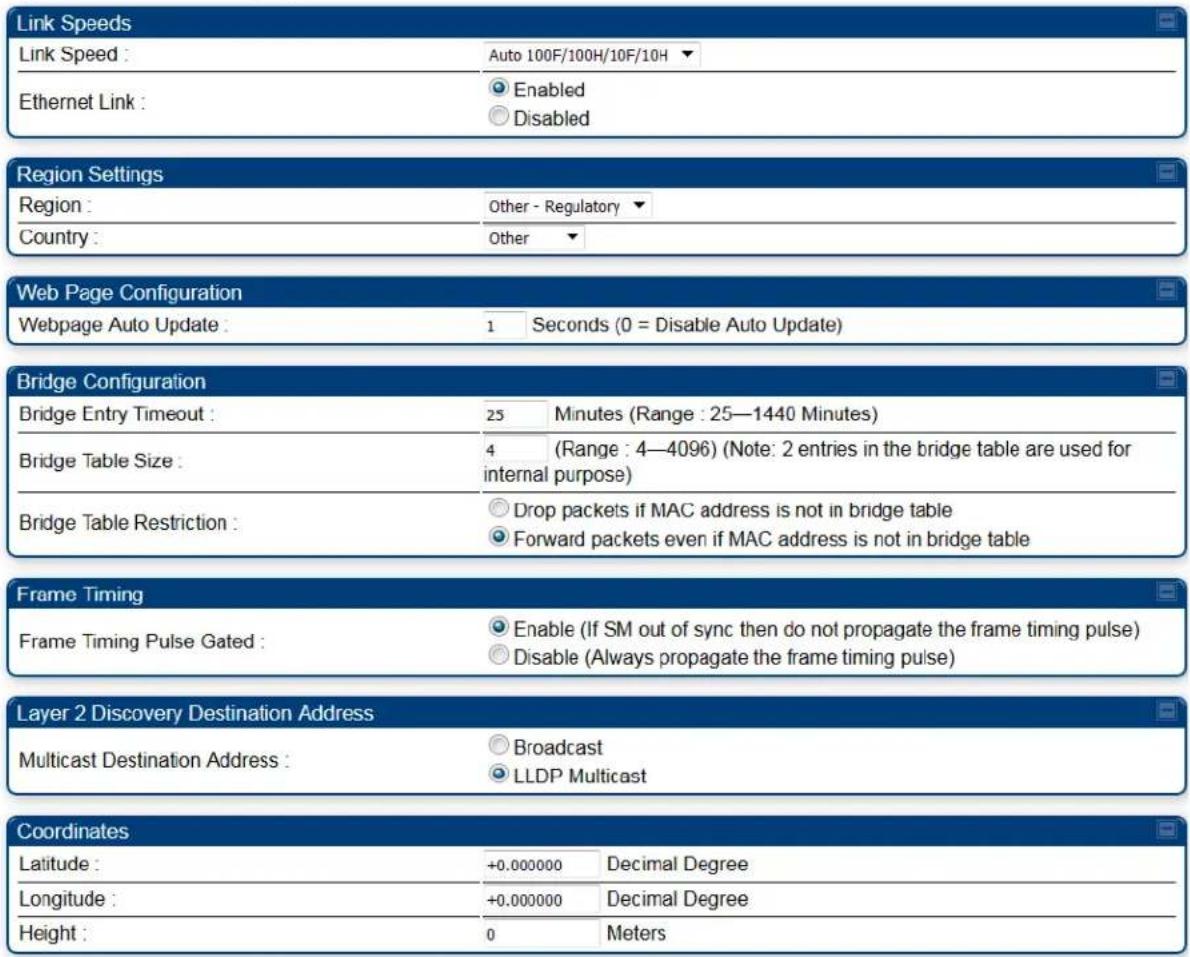
General page - PTP 450 BHM
Figure 143 General page attributes - PTP 450 BHM
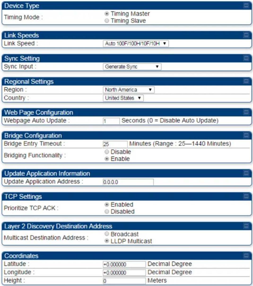
General page - PTP 450 BHS
Figure 144 General page attributes - PTP 450 BHS
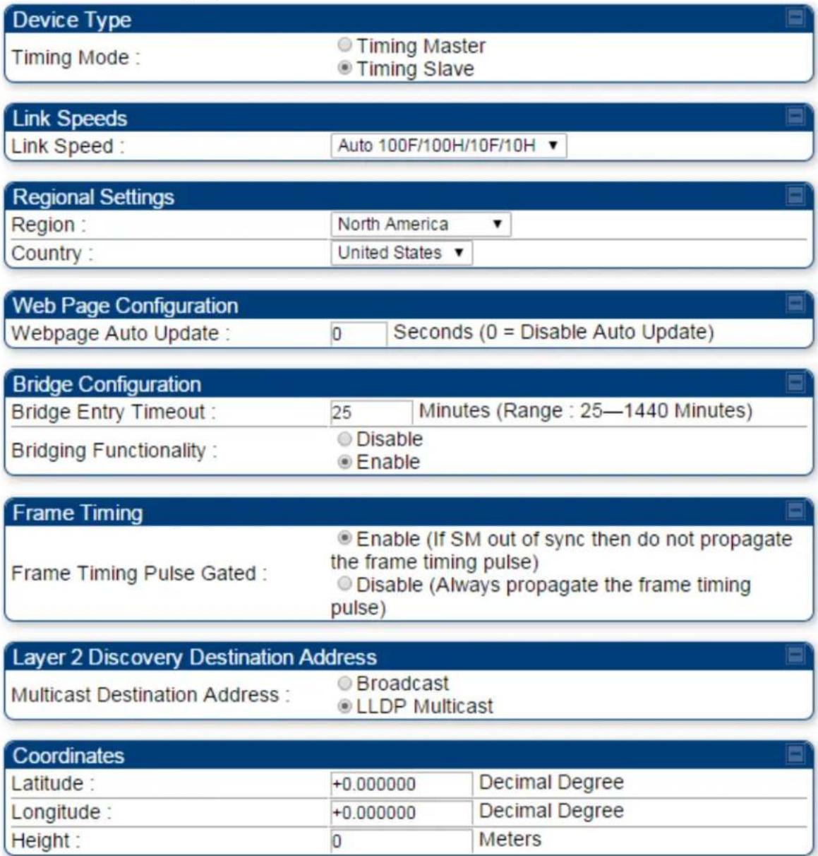
Configuring Unit Settings page
Applicable products
PMP:

AP

SM
PTP:

BHM

BMS
The Unit Settings page of the 450 Platform Family contains following options:
• Unit-Wide Changes
- Download Configuration File
- Upload and Apply Configuration File (for AP and BHM)
• LED Panel Settings (for SM and BHS)

Note
LED Panel setting is applicable for SM and BHS only.
Upload and Apply Configuration File attributes are not supported for SM and BHS.
The 450 Platform Family also supports import and export of configuration from the AP/BHM/SM/BHS as a text file. The configuration file is in JSON format. The logged in user must be an ADMINISTRATOR in order to export or import the configuration file.
The exported configuration file contains the complete configuration including all the default values. To keep a backup of the current configuration, the file can be saved as-is and imported later.
The configuration file supports encrypted password. The exported configuration file will contain encrypted password. The import of configuration can have either encrypted or plain text password in Configuration file. A new tab Encrypt the Password is added under Encrypted Password tab to generate encrypted password for a given password.
The Import and Export procedure of configuration file is described in Import and Export of config file on page 7-265.
LED Panel Mode has options select Revised mode and Legacy mode. The Legacy mode configures the radio to operate with standard LED behavior.
Unit Settings page of 450 Platform Family - AP/BHM
The Unit Setting page of AP/BHM is explained in Table 140.
Table 140 Unit Settings attributes - 450 Platform Family AP/BHM
| Default Plug Mode | ||
| Set To Factory Defaults Upon Default | Enabled | |
| Plug Mode Detection : | Disabled | |
| Unit-Wide Changes | ||
| Undo Unit-Wide Saved Changes | Set to Factory Defaults | |
| Encrypt the Password | ||
| Password : | ||
| Encrypted Password : | Encrypt the password | |
| Download Configuration File | ||
| Configuration File : | 0a003ea13575.cfg | |
| Upload and Apply Configuration File | ||
| File: Choose File No file chosen | ||
| Upload | ||
| Apply Configuration File | ||
| Status of Configuration File | ||
| Attribute | Meaning | |
| Set to Factory Defaults Upon Default Mode Detection | If Enabled is checked, then the default mode functions is enabled. When the module is rebooted with Default mode enabled, it can be accessed at the IP address 169.254.1.1 and no password, and all parameter values are reset to defaults. A subscriber, technician, or other person who gains physical access to the module and uses an override cannot see or learn the settings that were previously configured in it.If Disabled is checked, then the default mode functions are disabled.See Radio recovery mode on page 1-26 | |
 | CautionWhen Set to Factory Defaults Upon Default Mode is set to Enable, the radio does not select all of the frequencies for Radio Frequency Scan Selection List. It needs to be selected manually. | |
| Undo Unit-Wide Saved Changes | When you click this button, any changes that you made in any tab but did not commit by a reboot of the module are undone. | |
| Set to Factory Defaults | When you click this button, all configurable parameters on all tabs are reset to the factory settings. | |
 | NoteThis can be reverted by selecting "Undo Unit-Wide Saved Changes", before rebooting the radio, though this is not recommended. | |
| Password | This allows to provide encrypted password for a given password. On click of 'Encrypt the password' button, the Encrypted Password field will display encrypted value of entered plain text password in 'Password' field. | |
| Configuration File | This allows to download the configuration file of the radio. This configuration file contains the complete configuration including all the default values. The configuration file is highlighted as downloadable link and the naming convention is".cfg". | |
| Apply Configuration File | This allows to import and apply configuration to the AP.Chose File: Select the file to upload the configuration. The configuration file is named as ".cfg".Upload: Import the configuration to the AP.Apply Configuration File: Apply the imported configuration file to the AP. The imported configuration file may either contain a full device configuration or a partial device configuration. If a partial configuration file is imported, only the items contained in the file will be updated, the rest of the device configuration parameters will remain the same. Operators may also include a special flag in the configure file to instruct the device to first revert to factory defaults then to apply the imported configuration. | |
| Status of Configuration file | This section shows the results of the upload. | |
Unit Settings page of PMP/PTP 450i SM/BHS
The Unit Settings page of PMP/PTP 450i SM/BHS is explained in Table 141.
Table 141 SM Unit Settings attributes
| Default Plug Mode | |
| Set To Factory Defaults Upon Default Plug | Enabled |
| Mode Detection : | Disabled |
| LED Panel Settings | |
| LED Panel Mode : | Revised Mode (Optimized For Indoor SM)Legacy Mode |
| Unit-Wide Changes | |
| Undo Unit-Wide Saved Changes Set to Factory Defaults | |
| Encrypt the Password | |
| Password : | |
| Encrypted Password : | Encrypt the password |
| Download Configuration File | |
| Configuration File : | 0a003ea0a066.cfg |
| Upload and Apply Configuration File | |
| Configuration file import is currently unsupported over the web proxy. | |
| Status of Configuration File | |
| Attribute | Meaning |
| Set to Factory Defaults Upon Default Plug Detection | See Table 140 Unit Settings attributes - 450 Platform Family AP/BHM on page 7-97 |
| LED Panel Settings | Legacy Mode configures the radio to operate with standard LED behavior. |
| Undo Unit-Wide Saved Changes | |
| Password | |
| Set to Factory Defaults | See Table 140 Unit Settings attributes - 450 Platform Family AP/BHM on page 7-97 |
| Configuration File | |
| Status of Configuration file |
Setting up time and date
Time page of 450 Platform Family - AP/BHM
Applicable products
PMP: ☑ AP
PTP: ☑ BHM
The Time page of 450 Platform Family AP/BHM is explained in Table 142.
Table 142 450 Platform Family - AP/BHM Time attributes
| NTP Server Configuration | |
| NTP Server (Name or IP Address) : | Append DNS Domain NameDisable DNS Domain Name |
| NTP Server 1 (Name or IP Address) : | pool.ntp.org |
| NTP Server 2 (Name or IP Address) : | 0.0.0.0 |
| NTP Server 3 (Name or IP Address) : | 0.0.0.0 |
| NTP Server(s) In Use : | pool.ntp.org (108.61.73.244)Get Time via NTP |
| Current System Time | |
| Time Zone : | UTC : (UTC) Coordinated Universal Time |
| System Time : | 20:33:13 06/26/2013 UTC |
| Last NTP Time Update : | 20:32:07 06/26/2013 UTC |
| Time and Date | ||||
| Time : | 20 | : | 33 | : 13 UTC |
| Date : | 06 | / | 26 | / 2013 |
| Set Time and Date | ||||
| NTP Update Log |
| 06/26/2013 : 20:32:07 UTC : Clock Updated, Server 1 |
| Attribute | Meaning |
| NTP Server (Name or IP Address) | The management DNS domain name may be toggled such that the name of the NTP server only needs to be specified and the DNS domain name is automatically appended to that name. |
| NTP Server 1 (Name or IP Address) | To have each log in the AP/BHM correlated to a meaningful time and date, either a reliable network element must pass time and date to the AP/BHM or must set the time and date whenever a power cycle of the AP/BHM has occurred. A network element passes time and date in any of the following scenarios: |
| NTP Server 2 (Name or IP Address) | |
| NTP Server 3 (Name or IP Address) | A connected CMM4 passes time and date (GPS time and date, if received).A connected CMM4 passes the time and date (GPS time and date, if received), but only if both the CMMr is operating on CMMr Release 2.1 or later release. (These releases include NTP server functionality.)A separate NTP server (including APs/BHMs receiving NTP data) is addressable from the AP/BHM.If the AP/BHM needs to obtain time and date from a CMM4, or a separate NTP server, enter the IP address or DNS name of the CMM4 or NTP server on this tab. To force the AP/BHM to obtain time and date before the first (or next) 15-minute interval query of the NTP server, click Get Time via NTP.The polling of the NTP servers is done in a sequential fashion, and the polling status of each server is displayed in the NTP Update Log section of the Time Configuration page. An entry of 0.0.0.0 in any of the NTP Server fields indicates an unused server configuration. |
| NTP Server(s) in Use | Lists the IP addresses of servers used for NTP retrieval. |
| Time Zone | The Time Zone option may be used to offset the received NTP time to match the operator's local time zone. When set on the AP/BHM, the offset is set for the entire sector SMs (or BHS) are notified of the current Time Zone upon initial registration). If a Time Zone change is applied, the SMs (or BHS) is notified of the change in a best effort fashion, meaning some SMs//BHSs may not pick up the change until the next re-registration. Time Zone changes are noted in the Event Log of the AP/BHM and SM/BHS. |
| System Time The current time used by the system. | |
| Last NTP Time Update | The last time that the system time was set via NTP. |
| Time | This field may be used to manually set the system time of the radio. |
| Date | This field may be used to manually set the system date of the radio. |
| NTP Update Log This field shows NTP clock update log. It includes NTP clock update Date and Time stamp along with server name. | |
Configuring synchronization
Applicable products
PMP: ☑ AP
PTP: √ BHM
This section describes synchronization options for PMP and PTP configuration.
This Sync Input parameter can be configured under Sync Setting tab of Configure > General page (see General configuration on page 7-73).
PMP/PTP 450i Series has following synchronization options:
- AutoSync
• AutoSync + Free Run - Generate Sync
• Free Run Before GPS Sync
Figure 145 Sync Setting configuration

AutoSync
For PTP, the BHM automatically receives sync from one of the following sources:
- GPS Sync over Timing Port (UGPS, co-located AP GPS sync output, or “Remote” Device feed from a registered SM’s GPS sync output)
• GPS Sync over Power Port (CMM4)
Upon AP/BM power on, the AP/BHM does not transmit until a valid synchronization pulse is received from one of the sources above. If there is a loss of GPS synchronization pulse, within two seconds the AP/BHM automatically attempts to source GPS signaling from another source.
In case of PMP, when there are synchronization sources on both the timing port and the power port, the power port GPS source is chosen first.
If no valid GPS signal is received, the AP/BHM ceases transmission and SM/BHS registration is lost until a valid GPS signal is received again on the AP or BHM.

Note
After an AP reboot, the sync acquisition takes a little longer than it had on 450i (anywhere from 40 seconds to 120 seconds difference).
AutoSync + Free Run
This mode operates similarly to mode “AutoSync”, but if a previously received synchronization signal is lost and no GPS signaling alternative is achieved, the AP/BHM automatically changes to synchronization mode “Generate Sync”. While SM registration ins maintained, in this mode there is no synchronization of APs/BHMs that can “hear” each other; the AP/BHM will only generate a sync signal for the local AP/BHM and its associated SMs/BHS. Once a valid GPS signal is obtained again, the AP/BHM automatically switches to receiving synchronization via the GPS source and SM/BHS registration is maintained.
When the Sync Input field is set to Autosync or Autosync + Free Run, other options become available to be set e.g. UGPS Power and other fields. This is true on APs and BHMs.

Note
In mode AutoSync + Free Run, if a GPS signal is never achieved initially, the system will not switch to "Free Run" mode, and SMs/BHS will not register to the AP/BHM. A valid GPS signal must be present initially for the AP to switch into "Free Run" mode (and to begin self-generating a synchronization pulse).
Also, when an AP/BHM is operating in “Free Run” mode, over a short time it will no longer be synchronized with co-located or nearby APs/BHMs (within radio range). Due to this lack of transmit and receive synchronization across APs/BHMs or across systems, performance while in “Free Run” mode may be degraded until the APs/BHMs operating in “Free Run” mode regain a external GPS synchronization source. Careful attention is required to ensure that all systems are properly receiving an external GPS synchronization pulse, and please consider “Free Run” mode as an emergency option.
Generate Sync (factory default)
This option may be used when the AP/BHM is not receiving GPS synchronization pulses from either a CMM4 or UGPS module, and there are no other APs/BHMs active within the link range. Using this option will not synchronize transmission of APs/BHMs that can “hear” each other; it will only generate a sync signal for the local AP/BHM and its associated SMs/BHS.

Note
When an AP/BHM has its "Regional Code" set to "None", The radio will not provide valid Sync Pulse Information.
There is a RED warning that the radio will not transmit, but the user might expect to see a valid sync if the radio is connected to a working CMM4 or UGPS.
Configuring security
Perform this task to configure the 450 Platform system in accordance with the network operator's security policy. Choose from the following procedures:
- Managing module access by password on page 7-105: to configure the unit access password and access level
- Isolating from the internet on page 7-108: to ensure that APs are properly secured from external networks
- Encrypting radio transmissions on page 7-108: to configure the unit to operate with AES wireless link security
- Requiring SM Authentication on page 7-109: to set up the AP to require SMs to authenticate via the AP, WM, or RADIUS server
- Filtering protocols and ports on page 7-110: to filter (block) specified protocols and ports from leaving the system
- Encrypting downlink broadcasts on page 7-113: to encrypt downlink broadcast transmissions
- Isolating SMs on page 7-113: to prevent SMs in the same sector from directly communicating with each other
- Filtering management through Ethernet on page 7-114: to prevent management access to the SM via the radio's Ethernet port
- Allowing management only from specified IP addresses on page 7-114: to only allow radio management interface access from specified IP addresses
- Restricting radio Telnet access over the RF interface on page 7-114: to restrict Telnet access to the AP
- Configuring SNMP Access on page 7-117
- Configuring Security on page 7-119
Managing module access by password
| Applicable products | PMP: ☑ AP ☑ SM | PTP: ☑ BHM ☑ BMS |
See Managing module access by passwords on page 3-44.
Adding a User for Access to a module
The Account > Add User page allows to create a new user for accessing 450 Platform Family - AP/SM/BHM/BHS. The Add User page is explained in Table 143.
Table 143 Add User page of account page - AP/ SM/BH
| Add User | |
| User Name : | |
| Level : | INSTALLER ▼ |
| New Password : | |
| Confirm Password : | |
| User Mode : | read-onlyAdd |
| Account Status | |
| Attribute | Meaning |
| User Name User Account name. | |
| Level | Select appropriate level for new account. It can be INSTALLER, ADMINISTRATOR or TECHNICIAN. See Managing module access by passwords on page 3-44. |
| New Password Assign the password for new user account | |
| Confirm Password | This new password must be confirmed in the “Confirm Password” field. |
| User Mode | User Mode is used to create an account which are mainly used for viewing the configurations.The local and remote Read-Only user account can be created by “Admin”, “Installer” or “Tech” logins. To create a Read-Only user, the “read-only” check box needs to be checked. |

Note
The Read-Only user cannot perform any service impacting operations like creating read-only accounts, editing and viewing read-only user accounts, changes in login page, read-only user login, Telnet access, SNMP, RADIUS and upgrade/downgrade.
Deleting a User from Access to a module
The Account > Delete User page provides a drop-down list of configured users from which to select the user you want to delete. The Delete User page is explained in Table 144.
Table 144 Delete User page - 450 Platform Family - AP/ SM/BH
| Delete UserUser: admin ▼Delete | |
| Account Status | |
| Attribute | Meaning |
| User | Select a user from drop-down list which has to be deleted and click Delete button.Accounts that cannot be deleted arethe current user's own account.the last remaining account of ADMINISTRATOR level. |
Changing a User Setting
The Account > Change User Setting page allows to update password, mode update and general status permission for a user.
From the factory default state, configure passwords for both the root and admin account at the ADMINISTRATOR permission level, using Update Password tab of Change Users Setting page.
The Change User Setting page is explained in Table 145.
Table 145 Change User Setting page - 450 Platform Family AP/ SM/BH
| Update Password | |
| User : | admin ▼ |
| New Password : | |
| Confirm Password : | |
| Change Password | |
| Update Mode | |
| User : | test ▼ |
| User Mode : | read-onlyChange Mode |
| General Status Permission | |
| General Status Page Viewable to Guest Users : | EnabledDisabledChange Permission |
| Account Status | |
| Attribute | Meaning |
| Update Password tab | This tab provides a drop-down list of configured users from which a user is selected to change password. |
| Update Mode tab | This tab facilitates to convert a configured user to a Read-Only user. |
| General Status Permission tab | This tab enables and disables visibility of General Status Page for all Guest users.To display of Radio data on SMs/BHS main Login page for Guest login, it can be enabled or disabled in Security tab of Configuration page. |
Figure 146 AP Evaluation Configuration parameter of Security tab for PMP

Figure 147 BHM Evaluation Configuration parameter of Security tab for PTP

Users account
The Account > Users page allows to view all configured users account for accessing the module.
The Users page is explained in Table 146.
Table 146 User page -450 Platform Family AP/SM/BH
| Username | Permission | Mode |
| admin | ADMINISTRATOR | Read-Write |
| root | ADMINISTRATOR | Read-Write |
| ins | INSTALLER | Read-Write |
| Attribute | Meaning |
| Username | User access account name |
| Permission | Permission of configured user - INSTALLER, ADMINISTRATOR or TECHNICIAN |
| Mode | This field indicate access mode of user - Read-Write or Read-Only. |
Overriding Forgotten IP Addresses or Passwords on AP and SM
See Radio recovery mode on page 1-26
Isolating from the internet - APs/BHMs
Applicable products
PMP: ☑ AP
PTP: √ BHM
See Isolating AP/BHM from the Internet on page 3-42.
Encrypting radio transmissions
Applicable products
PMP: ☑ AP
SM
PTP: √ BHM √ BMS
See Encrypting radio transmissions on page 3-42.
Requiring SM Authentication
Applicable products
PMP: ☑ AP ☑ SM
Through the use of a shared AP key, or an external RADIUS (Remote Authentication Dial In User Service) server, it enhances network security by requiring SMs to authenticate when they register.
For descriptions of each of the configurable security parameters on the AP, see Configuring Security on page 7-119. For descriptions of each of the configurable security parameters on the SM, see Security page - 450 Platform Family BHM on page 7-125.
Operators may use the AP's Authentication Mode field to select from among the following authentication modes:
- Disabled—the AP requires no SMs to authenticate (factory default setting).
- Authentication Server —the AP requires any SM that attempts registration to be authenticated in Wireless Manager before registration
- AP PreShared Key - The AP acts as the authentication server to its SMs and will make use of a user-configurable pre-shared authentication key. The operator enters this key on both the AP and all SMs desired to register to that AP. There is also an option of leaving the AP and SMs at their default setting of using the "Default Key". Due to the nature of the authentication operation, if you want to set a specific authentication key, then you MUST configure the key on all of the SMs and reboot them BEFORE enabling the key and option on the AP. Otherwise, if you configure the AP first, none of the SMs is able to register.
- RADIUS AAA - When RADIUS AAA is selected, up to 3 Authentication Server (RADIUS Server) IP addresses and Shared Secrets can be configured. The IP address(s) configured here must match the IP address(s) of the RADIUS server(s). The shared secret(s) configured here must match the shared secret(s) configured in the RADIUS server(s). Servers 2 and 3 are meant for backup and reliability, not for splitting the database. If Server 1 doesn't respond, Server 2 is tried, and then server 3. If Server 1 rejects authentication, the SM is denied entry to the network, and does not progress trying the other servers.
For more information on configuring the PMP 450 Platform network to utilize a RADIUS server, see Configuring a RADIUS server on page 7-273.
Filtering protocols and ports
| Applicable products | PMP: ☑ AP ☑ SM | PTP: ☑ BHM ☑ BMS |
The filtering protocols and ports allows to configure filters for specified protocols and ports from leaving the AP/SM/BHM/BHS and entering the network. See Filtering protocols and ports on page 3-45.
Protocol filtering page of 450 Platform Family AP/BHM
The Protocol Filtering page of 450 Platform Family - AP/BHM is explained in Table 147.
Table 147 AP/BHM Protocol Filtering attributes

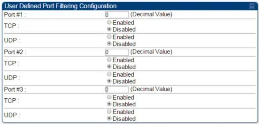

| Attribute | Meaning |
| Packet Filter Types | For any box selected, the Protocol and Port Filtering feature blocks the associated protocol type.To filter packets in any of the user-defined ports, must do all of the following:Check the box for User Defined Port n (See Below) in the Packet Filter Types section of this tab.In the User Defined Port Filtering Configuration section of this tab:provide a port number at Port #n.enable TCP and/or UDP by clicking the associated radio button |
| Filter Direction | Operators may choose to filter upstream (uplink) RF packets or downstream (downlink) RF packets. |
| User Defined Port Filtering Configuration | You can specify ports for which to block subscriber access, regardless of whether NAT is enabled. |
| RF Telnet Access | RF Telnet Access restricts Telnet access to the AP/BHM from a device situated below a network SM/BHS (downstream from the AP/BHM). This is a security enhancement to restrict RF-interface sourced AP access specifically to the LAN1 IP address and LAN2 IP address (Radio Private Address, typically 192.168.101.[LUID]). This restriction disallows unauthorized users from running Telnet commands on the AP/BHM that can change AP/BHM configuration or modifying network-critical components such as routing and ARP tables. |
| PPPoE PADI Downlink Forwarding | Enabled: the AP/BHM allows downstream and upstream transmission of PPPoE PADI packets. By default, PPPoE PADI Downlink Forwarding is set to “Enabled”.Disabled: the AP/BHM disallows PPPoE PADI packets from entering the Ethernet interface and exiting the RF interface (downstream to the SM/BHS). PPPoE PADI packets are still allowed to enter the AP’s RF interface and exit the AP’s /BHM’s Ethernet interface (upstream). |
Protocol filtering page of SM/BHS
The Protocol Filtering page of SM/BHS is explained in Table 148.
Table 148 SM/BHS Protocol Filtering attributes

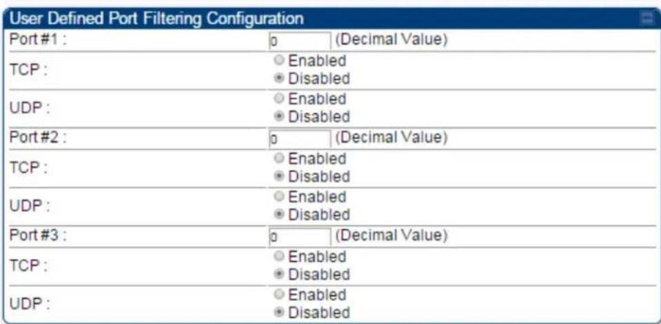
| Attribute | Meaning |
| Packet Filter Configuration tab | See Table 147 AP/BHM Protocol Filtering attributes on page 7-110 |
| User Defined Port Filtering Configuration tab | See Table 147 AP/BHM Protocol Filtering attributes on page 7-110 |
Port configuration
450 Platform Family ODUs support access to various communication protocols and only the ports required for these protocols are available for access by external entities. Operators may change the port numbers for these protocols via the radio GUI or SNMP.
The Port Configuration page of the AP/SM/BHM/BHS is explained in Table 149.
Table 149 Port Configuration attributes - AP/SM/BHM/BMS
| Port Configuration | ||
| FTP Port : | 21 | Default port number is 21 |
| HTTP Port : | 80 | Default port number is 80 |
| HTTPS Port : | 443 | Default port number is 443 |
| Radius Port : | 1812 | Default port number is 1812 |
| Radius Accounting Port : | 1813 | Default port number is 1813 |
| SNMP Port : | 161 | Default port number is 161 |
| SNMP Trap Port : | 162 | Default port number is 162 |
| Syslog Server Port : | 514 | Default port number is 514 |
| Attribute | Meaning |
| FTP Port | The listen port on the device used for FTP communication. |
| HTTP Port | The listen port on the device used for HTTP communication. |
| HTTPS Port | The listen port on the device used for HTTPS communication |
| Radius Port | The destination port used by the device for RADIUS communication. |
| Radius Accounting Port | The destination port used by the device for RADIUS accounting communication. |
| SNMP Port | The listen port on the device used for SNMP communication. |
| SNMP Trap Port | The destination port used by the device to which SNMP traps are sent. |
| Syslog Server Port | The destination port used by the device to which Syslog messaging is sent. |
Encrypting downlink broadcasts
See Encrypting downlink broadcasts on page 3-49.
Isolating SMs
See Isolating SMs in PMP on page 3-49.
Filtering management through Ethernet
See Filtering management through Ethernet on page 3-49.
Allowing management only from specified IP addresses
See Allowing management from only specified IP addresses on page 3-50.
Restricting radio Telnet access over the RF interface
RF Telnet Access restricts Telnet access to the AP from a device situated below a network SM (downstream from the AP). This is a security enhancement to restrict RF-interface sourced AP access specifically to the LAN1 IP address and LAN2 IP address (Radio Private Address, typically 192.168.101. [LUID]). This restriction disallows unauthorized users from running Telnet commands on the AP that can change AP configuration or modifying network-critical components such as routing and ARP tables.
The RF Telnet Access may be configured via the AP GUI or via SNMP commands, and RF Telnet Access is set to "Enabled" by default. Once RF Telnet Access is set to "Disabled", if there is a Telnet session attempt to the AP originating from a device situated below the SM (or any downstream device), the attempt is dropped. This also includes Telnet session attempts originated from the SM's management interface (if a user has initiated a Telnet session to a SM and attempts to Telnet from the SM to the AP). In addition, if there are any active Telnet connections to the AP originating from a device situated below the SM (or any downstream device), the connection is dropped. This behavior must be considered if system administrators use Telnet downstream from an AP (from a registered SM) to modify system parameters.
Setting RF Telnet Access to “Disabled” does not affect devices situated above the AP from accessing the AP via Telnet, including servers running the CNUT (Canopy Network Updater tool) application. Also, setting RF Telnet Access to “Disabled” does not affect any Telnet access into upstream devices (situated above or adjacent to the AP) through the AP (see Figure 148).
The figure below depicts a user attempting two telnet sessions. One is targeted for the AP (orange) and one is targeted for the network upstream from the AP (green). If RF Telnet Access is set to “Disabled” (factory default setting), the Telnet attempt from the user to the AP is blocked, but the attempt from the user to Network is allowed to pass through the Cambium network.
Figure 148 RF Telnet Access Restrictions (orange) and Flow through (green)
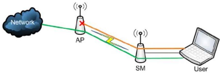
flowchart
graph LR
    A["Network"] --> B["AP"]
    B --> C["SM"]
    C --> D["User"]
    style A fill:#f9f,stroke:#333
    style B fill:#ccf,stroke:#333
    style C fill:#cfc,stroke:#333
    style D fill:#fcc,stroke:#333
Key Security Considerations when using the RF Telnet Access Feature
To ensure that the network is fully protected from unauthorized AP Telnet sessions, the following topics must be considered:
Securing AP Clusters
When working with a cluster of AP units, to eliminate potential security holes allowing Telnet access, ensure that the RF Telnet Access parameter is set to “Disabled” for every AP in the cluster. In addition, since users situated below the AP are able to pass Telnet sessions up through the SM and AP to the upstream network (while AP RF Telnet Access is set to “Disabled”), ensure that all CMM4 or other networking equipment is secured with strong passwords. Otherwise, users may Telnet to the CMM4 or other networking equipment, and subsequently access network APs (see Figure 149) via their Ethernet interfaces (since RF Telnet Access only prevents Telnet sessions originating from the AP’s wireless interface).
Figure 149 RF Telnet Access Restriction (orange) and Potential Security Hole (green)
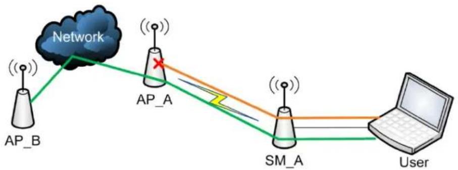
flowchart
graph TD
    A["AP_B"] --> B["Network"]
    B --> C["AP_A"]
    C --> D["SM_A"]
    D --> E["User"]
    C -->|Red X| C
    style A fill:#f9f,stroke:#333
    style B fill:#ccf,stroke:#333
    style C fill:#cfc,stroke:#333
    style D fill:#fcc,stroke:#333
    style E fill:#cff,stroke:#333
As a common practice, AP administrator usernames and passwords must be secured with strong, non-default passwords.
Restricting AP RF Telnet Access
AP Telnet access via the RF interface may be configured in two ways - the AP GUI and SNMP.
Controlling RF Telnet Access via the AP GUI
To restrict all Telnet access to the AP via the RF interface from downstream devices, follow these instructions using the AP GUI:
Procedure 20 Restricting RF Telnet access
1 Log into the AP GUI using administrator credentials
2 On the AP GUI, navigate to Configuration > Protocol Filtering
3 Under GUI heading "Telnet Access over RF Interface", set RF Telnet Access to Disabled

4 Click the Save button
5 Once the Save button is clicked, all RF Telnet Access to the AP from devices situated below the AP is blocked.

Note
The factory default setting for RF Telnet Access is disabled and PPPoE PADI Downlink Forwarding is enabled.
Configuring SNMP Access
The SNMPv3 interface provides a more secure method to perform SNMP operations. This standard provides services for authentication, data integrity and message encryption over SNMP. Refer to Planning for SNMPv3 operation on page 3-43 for details.

Note
The factory default setting for SNMP is "SNMPv2c Only".
Procedure 21 Configuring SNMPv3
1 Log into the AP GUI using administrator credentials
2 On the AP/SM GUI, navigate to Configuration > Security Page
3 Under GUI heading "Security Mode", set SNMP to SNMPv3 Only

4 Click the Save Changes button
5 Go to Configuration > SNMP Page
6 Under GUI heading "SNMPv3 setting", set Engine ID, SNMPv3 Security Level, SNMPv3 Authentication Protocol, SNMPv3 Privacy Protocol, SNMPv3 Read-Only User, SNMPv3 Read/Write User, SNMPv3 Trap Configuration parameters:
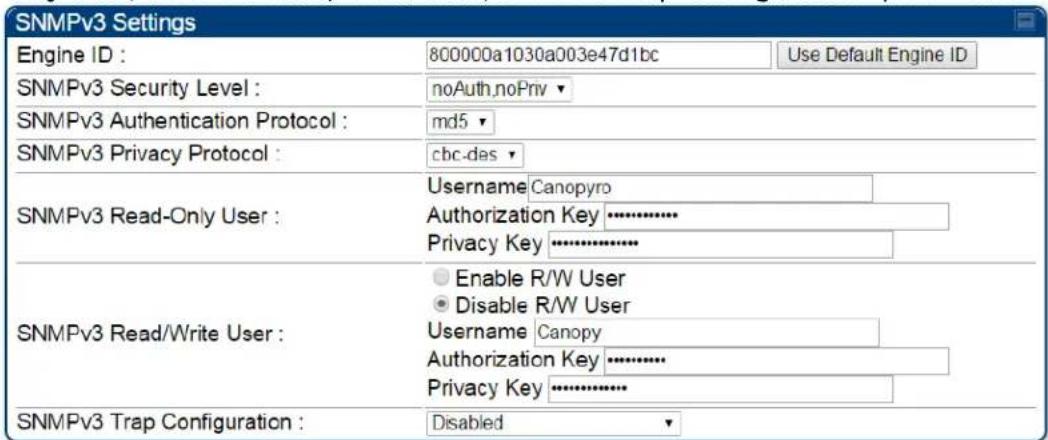
Engine ID:
Each radio (AP/SM/BHM/BHS) has a distinct SNMP authoritative engine identified by a unique Engine ID. While the Engine ID is configurable to the operator it is expected that the operator follows the guidelines of the SNMPEngineID defined in the SNMP-
FRAMEWORK-MIB (RFC 3411). The default Engine ID is the MAC address of the device.
SNMPv3 security level, Authentication and Privacy Protocol
The authentication allows authentication of SNMPv3 user and privacy allows for encryption of SNMPv3 message. 450 Platform Family supports MD5 authentication and CBC-DES privacy protocols.
SNMPv3 Read-Only and Read/Write User
The user can be defined by configurable attributes. The attributes and default values are:
- Read-only user
○ Username = Canopyro
- Authentication Password = authCanopyro
- Privacy Password = privacyCanopyro
- Read-write user (by default read-write user is disabled)
○ Username = Canopy
○ Authentication Password = authCanopy
- Privacy Password = privacyCanopy
SNMPv3 Trap Configuration
The traps may be sent from radios in SNMPv3 format based on parameter settings. It can be configured for Disabled, Enabled for Read-Only User, Enable for Read/Write User.
Configuring Security
| Applicable products | PMP: | ☑ | AP | ☑ | SM | PTP: | ☑ | BHM | ☑ | BMS |
Security page - 450 Platform Family AP
The security page of AP is explained in Table 150.
Table 150 Security attributes -450 Platform Family AP
| Authentication Server Settings | ||
| Authentication Mode: | Disabled | |
| Authentication Server DNS Usage: | Append DNS Domain NameDisable DNS Domain Name | |
| Authentication Server 1: | Shared Secret | |
| 0.0.0.0 | ||
| Authentication Server 2: | Shared Secret | |
| 0.0.0.0 | ||
| Authentication Server 3: | Shared Secret | |
| 0.0.0.0 | ||
| Authentication Server 4 (BAM ONLY): | 0.0.0.0 | |
| Authentication Server 5 (BAM ONLY): | 0.0.0.0 | |
| Radius Port: | 1812 | Default port number is 1812 |
| Authentication Key 128-bit: | (Using All 0xFF's Key) | |
| Select Key 128-bit: | Use Key aboveUse Default Key | |
| Disable AES-128: | AES-128 Encryption DisabledAES-128 Encryption Available | |
| Authentication Key 256-bit: | ||
| (Using All 0xFF's Key) | ||
| Select Key 256-bit: | Use Key aboveUse Default Key | |
| Dynamic Authorization Extensions for RADIUS: | Enable CoA and Disconnect MessageDisable CoA and Disconnect Message | |
| Bypass Authentication for ICC SMs: | EnabledDisabled | |

| Attribute | Meaning | |
| Authentication Mode | Operators may use this field to select from among the following authentication modes:Disabled-the AP requires no SMs to authenticate. (Factory default).Authentication Server -the AP/BHM requires any SM/BHS that attempts registration to be authenticated in Wireless Manager before registration.AP PreShared Key - The AP/BHM acts as the authentication server to its SMs/BHS and will make use of a user-configurable pre-shared authentication key. The operator enters this key on both the AP/BHM and all SMs/BHS desired to register to that AP/BHM. There is also an option of leaving the AP/BHM and SMs/BHS at their default setting of using the “Default Key”. Due to the nature of the authentication operation, if you want to set a specific authentication key, then you MUST configure the key on all of the SMs/BHS and reboot them BEFORE enabling the key and option on the AP/BHM. Otherwise, if you configure the AP/BHM first, none of the SMs/BHS is able to register.RADIUS AAA - When RADIUS AAA is selected, up to 3 Authentication Server (RADIUS Server) IP addresses and Shared Secrets can be configured. The IP address(s) configured here must match the IP address(s) of the RADIUS server(s). The shared secret(s) configured here must match the shared secret(s) configured in the RADIUS server(s). Servers 2 and 3 are meant for backup and reliability, not for splitting the database. If Server 1 doesn’t respond, Server 2 is tried, and then server 3. If Server 1 rejects authentication, the SM is denied entry to the network, and does not progress trying the other servers. | |
| Authentication Server DNS Usage | The management DNS domain name may be toggled such that the name of the authentication server only needs to be specified and the DNS domain name is automatically appended to that name. | |
| Authentication Server 1 to 5 | Enter the IP address or server name of the authentication server (RADIUS or WM) and the Shared Secret configured in the authentication server. When Authentication Mode RADIUS AAA is selected, the default value of Shared Secret is “CanopySharedSecret”. The Shared Secret may consist of up to 32 ASCII characters. | |
| Radius Port | This field allows the operator to configure a custom port for RADIUS server communication. The default value is 1812. | |
| Authentication Key 128-bit | This authentication key is a 32-character hexadecimal string used when Authentication Mode is set to AP PreShared Key. By default, this key is set to 0xFFFFFFFFFFFFFFFFFFFFFFFF | |
| Select Key 128-bit | This option allows operators to choose which authentication key is used: | |
| Use Key above means that the key specified in Authentication Key is used for authenticationUse Default Key means that a default key (based off the SM's MAC address) is used for authentication | ||
| Disable AES 128-bit | This option allows to disable the AES-128 encryption. When AES-128 Encryption is disabled, it prevents the use of AES-128 when encryption is enabled. Since changes to other attributes (e.g. PreSharedKey authentication settings) could cause a need for 128-bit Auth and AES-128 upon next registration, Disable AES 128-bit parameter is prevented from being changed on the "Security" webpage while the "Reboot Required" warning is present at the top of the Web GUI pages. The recommendation is to complete other changes first and to ensure that all links at an AP are running AES-256 before disabling the use of AES-128 on all units (AP and SMs) in the sector.When saving and loading a configuration file, Disable AES 128 is saved and loaded as a normal attribute. It will not take effect until a reboot is triggered. Since enabling this attribute could have the effect of preventing a link coming up, care should be taken on networks that enable this attribute on only some units.Select one of the following options to either disable or use AES-128 encryption.AES-128 Encryption Disabled:AES-128 Encryption Available | |
| Authentication Key 256-bit | This authentication key is a 64-character hexadecimal string used when Authentication Mode is set to AP PreShared Key. By default, this key is set to 0xFFFFFFFFFFFFFFFFFFFFFFFFFFFFFFFFFFFFFFFFFFFFFFFFFFFFFFFFFFFFFFFFFFFFFFFFFFFFFFFFFFFFFFFFFFFFFFFFFFFFFFFFFFFFFFFFFFFFFFFFFFFFFFFFFFFFFFFFFFFFFFFFFFFFFFFFFFFFFFFFFFFFFFFFFFFFFFFFFFFFFFFFFFFFFFFFFFFFFFFFFFFFFFFFFFFFFFFFFFFFFFFFFFFFFFFFFFFFFFFFFFFFFFFFFFFFFFFFFFFFFFFFFFFFFFFFFFFFFFFFFFFFFFFFFFFFFFFFFFFFFFFFFFFFFFFFFFFFFFFFFFFFFFFFFFFFFFFFFFFFFFFFFFFFFFFFFFFFFFFFFFFFFFFFFFFFFFFFFFFFFFFFFFFFFFFFFFFFFFFFFFFFFFFFFFFFFFFFFFFFFFFFFFFFFFFFFFFFFFFFFFFFFFFFFFFFFFFFFFFFFFFFFFFFFFFFFFFFFFFFFFFFFFFFFFFFFFFFFFFFFFFFFFFFFFFFFFFFFFFFFFFFFFFFFFFFFFFFFFFFFFFFFFFFFFFFFFFFFFFFFFFFFFFFFFFFFFFFFFFFFFFFFFFFFFFFFFFFFFFFFFFFFFFFFFFFFFFFFFFFFFFFFFFFFFFFFFFFFFFFFFFFFFFFFFFFFFFFFFFFFFFFFFFFFFFFFFFFFFFFFFFFFFFFFFFFFFFFFFFFFFFFFFFFFFFFFFFFFFFFFFFFFFFFFFFFFFFFFFFFFFFFFFFFFFFFFFFFFFFFFFFFFFFFFFFFFFFFFFFFFFFFFFFFFFFFFFFFFFFFFFFFFFFFFFFFFF | |
 | NoteThe AES-256 parameters are visible only when the feature key is purchased. | |
| Select Key 256-bit | This option allows operators to choose which authentication key is used:Use Key above means that the key specified in Authentication Key is used for authenticationUse Default Key means that a default key (based off of the SM's MAC address) is used for authentication | |
 | NoteThe AES-256 parameters are visible only when the feature key is purchased. | |
| Dynamic Authorization Extensions for RADIUS | Enable CoA and Disconnect Message : Allows to control configuration parameters of SM using RADIUS CoA and Disconnect Message feature. Disable CoA and Disconnect Message : Disables RADIUS CoA and Disconnect Message feature. To enable CoA and Disconnect feature, the Authentication Mode should be set to RADIUS AAA. | |
| Bypass Authentication for ICC SMs | Enabled: SM authentication is disabled when SM connects via ICC (Installation Color Code). Disabled: SM authentication is enabled. | |
| Encryption Setting | Specify the type of airlink security to apply to this AP. The encryption setting must match the encryption setting of the SMs. None provides no encryption on the air link. AES (Advanced Encryption Standard): An over-the-air link encryption option that uses the Rijndael algorithm and 128-bit keys to establish a higher level of security. AES products are certified as compliant with the Federal Information Processing Standards (FIPS 197) in the U.S.A. | |
 | Note This parameter is applicable to BHM. | |
| SM Display of AP Evaluation Data Or BHS Display of BHM Evaluation Data | Allows operators to suppress the display of data about this AP/BHM on the AP/BHM Evaluation tab of the Tools page in all SMs/BHS that register. The factory default setting for SM Display of AP Evaluation Data or BHS Display of BHM Evaluation Data is enabled display. PMP 450/450i Series - SM display of AP Evaluation Data parameter  | |
PTP 450/450i Series - BHS display of BHM Evaluation Data parameter  | ||
| Web, Telnet, FTP Session Timeout | Enter the expiry in seconds for remote management sessions via HTTP, telnet, or ftp access to the AP/BHM. | |
| IP Access Control | You can permit access to the AP/BHM from any IP address (IP Access Filtering Disabled) or limit it to access from only one, two, or three IP addresses that you specify (IP Access Filtering Enabled). If you select IP Access Filtering Enabled, then you must populate at least one of the three Allowed Source IP parameters or have no access permitted from any IP address | |
| Allowed Source IP 1 to 3 | If you selected IP Access Filtering Enabled for the IP Access Control parameter, then you must populate at least one of the three Allowed Source IP parameters or have no access permitted to the AP from any IP address. You may populate as many as all three.If you selected IP Access Filtering Disabled for the IP Access Control parameter, then no entries in this parameter are read, and access from all IP addresses is permitted. | |
| Web Access | The Radio supports secured and non-secured web access protocols.Select suitable web access from drop-down list:HTTP Only - provides non-secured web access. The radio to be accessed via http://HTTPS Only - provides a secured web access. The radio to be accessed via https://HTTP and HTTPS - If enabled, the radio can be accessed via both http and https. | |
| SNMP | This option allows to configure SNMP agent communication version.It can be selected from drop-down list:SNMPv2c Only - Enables SNMP v2 community protocol.SNMPv3 Only - Enables SNMP v3 protocol. It is a secured communication protocol.SNMPv2c and SNMPv3 - It enables both the protocols. | |
| Telnet This option allows to | Enable and Disable Telnet access to the Radio. | |
| FTP This option allows to | Enable and Disable FTP access to the Radio. | |
| TFTP This option allows to | Enable and Disable TFTP access to the Radio. | |
| NTP Server This option allows to Radio. | Enable and Disable NTP server access to the Radio. | |
| Site Information viewable to Guest Users | This option allows to Enable or Disable displaying site information with Guest users. | |
| Site Name | Specify a string to associate with the physical module. | |
| Site Contact | Enter contact information for the module administrator. | |
| Site Location | Enter information about the physical location of the module. | |
| Enable Security Banner during Login | Enable: The Security Banner Notice will be displayed before login.Disable: The Security Banner Notice will not be displayed before login. | |
| Security Banner Notice | User can enter ASCII (0-9a-zA-Z newline, line-feed are allowed) text up-to 1300 characters. | |
| User must accept security banner before login | Enable: login area (username and password) will be disabled unless user accepts the security banner. | |
| Disable: User can't login to radio without accepting security banner. | ||
Security page - 450 Platform Family BHM
The security page of AP/BHM is explained in Table 151.
Table 151 Security attributes -450 Platform Family BHM
| Authentication Mode | ||
| Authentication Mode: | ● Authentication Required● Authentication Disabled | |
| Authentication Key 128-bit: | (Using All 0xFF's Key) | |
| Airlink Security | ||
| 24 Hour Encryption Refresh: | ● Enable● Disable | |
| Encryption Setting: | None ▼ | |
| BHM Evaluation Configuration | ||
| BHS Display of BHM Evaluation Data: | ● Disable Display● Enable Display | |
| Session Timeout | ||
| Web, Telnet, FTP Session Timeout: | 600 Seconds | |
| IP Access Filtering | ||
| IP Access Control: | ● IP Access Filtering Enabled - Only allow access from IP addresses specified below● IP Access Filtering Disabled - Allow access from all IP addresses | |
| Allowed Source IP 1: | 0.0.0.0 | / 32 Network Mask (set to 32 to disable) |
| Allowed Source IP 2: | 0.0.0.0 | / 32 Network Mask (set to 32 to disable) |
| Allowed Source IP 3: | 0.0.0.0 | / 32 Network Mask (set to 32 to disable) |
| Security Mode | ||
| Web Access: | HTTP Only ▼ | |
| SNMP: | SNMPv2c Only ▼ | |
| Telnet: | ● Enabled● Disabled | |
| FTP: | ● Enabled● Disabled | |
| TFTP: | ● Enabled● Disabled | |
| NTP server: | ● Enabled● Disabled | |


| Attribute | Meaning |
| Authentication Mode | Operators may use this field to select from among the following authentication modes: Authentication Required: the BHS requires to be authenticated. Authentication Disabled: the BHM requires no BHS to authenticate. (Factory default). |
| Authentication Key 128-bit | Refer Table 150 Security attributes -450 Platform Family AP on page 7-119 for parameter details |
| 24 Hour Encryption Refresh | Operators may use this field to select from among the following options: Enabled: Allows BHS re-registration every 24 hours. Disabled: Disables 24-hour encryption refresh. This parameter is disabled by default. |
| Encryption Setting | |
| BHS Display of BHM Evaluation Data | |
| Web, Telnet, FTP Session Timeout | |
| IP Access Control | |
| Allowed Source IP 1 to 3 | Refer Table 150 Security attributes -450 Platform Family AP on page 7-119 for parameter details |
| Web Access | |
| SNMP | |
| Telnet | |
| FTP | |
| TFTP | |
| NTP Server | |
| Site Information viewable to Guest Users | |
| Site Name | |
| Site Contact | |
| Site Location | |
| Enable Security Banner during Login | Refer Table 150 Security attributes -450 Platform Family AP on page 7-119 for parameter details |
| Security Banner Notice | |
| User must accept security banner before login | |
Security page - 450 Platform Family SM
The security page of 450 Platform Family SM is explained in Table 152.
Table 152 Security attributes -450 Platform Family SM
| Authentication Key Settings | |
| Authentication Key 128-bit : | (Using All 0xFF's Key) |
| Select Key 128-bit : | Use Key aboveUse Default Key |
| Disable AES-128 : | AES-128 Encryption DisabledAES-128 Encryption Available |
| Authentication Key 256-bit : | (Using All 0xFF's Key) |
| Select Key 256-bit : | Use Key aboveUse Default Key |
| AAA Authentication Settings | ||
| Enforce Authentication : | Disable | |
| Phase 1 : | eapttls | |
| Phase 2 : | MSCHAPv2 | |
| Identity/Realm : | Enable RealmDisable RealmIdentity anonymous @ Realm canopy.net | |
| Username : | 0a-00-3e-bb-40-d2 | Use Default Username |
| Password : | ********** | |
| Confirm Password : | ||
| RADIUS Certificate Settings | |
| Upload Certificate File | |
| File: | Browse... No file selected. |
| Import Certificate | |
| Use Default Certificates | |
| This will delete all current certificates | |

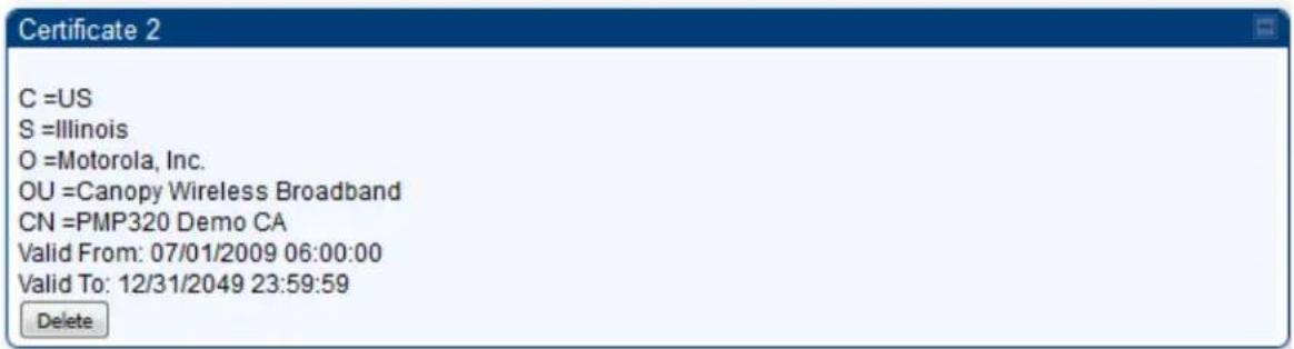




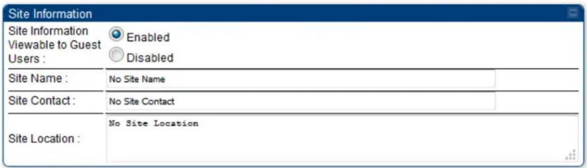

| Attribute | Meaning | |
| Authentication Key 128-bit | Only if the AP to which this SM will register requires authentication, specify the 128-bit key that the SM will use when authenticating. For alpha characters in this 32-character hex key, use only upper case. | |
| Select Key 128-bit | Refer Table 150 Security attributes -450 Platform Family AP on 7-119 for parameter details. | |
| Disable AES 128-bit | ||
| Authentication Key 256-bit | ||
| Select Key 256-bit | ||
| Enforce Authentication | The SM may enforce authentication types of AAA and AP Pre-sharedKey. The SM will not finish the registration process if the AP is not using the configured authentication method (and the SM locks out the AP for 15 minutes). | |
| Phase 1 | The protocols supported for the Phase 1 (Outside Identity) phase of authentication are EAPTTLS (Extensible Authentication Protocol Tunneled Transport Layer Security) or MSCHAPv2 (Microsoft Challenge-Handshake Authentication Protocol version 2). | |
| Phase 2 | Select the desired Phase 2 (Inside Identity) authentication protocol from the Phase 2 options of PAP (Password Authentication Protocol), CHAP (Challenge Handshake Authentication Protocol), and MSCHAP (Microsoft's version of CHAP, version 2 is used). The protocol must be consistent with the authentication protocol configured on the RADIUS server. | |
| Identity/Realm | If Realms are being used, select Enable Realm and configure an outer identity in the Identity field and a Realm in the Realm field. These must match the Phase 1/Outer Identity and Realm configured in the RADIUS server. The default Identity is “anonymous”. The Identity can be up to 128 non-special (no diacritical markings) alphanumeric characters. The default Realm is “canopy.net”. The Realm can also be up to 128 non-special alphanumeric characters. Configure an outer Identity in the Username field. This must match the Phase 1/Outer Identity username configured in the RADIUS server. The default Phase 1/Outer Identity Username is “anonymous”. The Username can be up to 128 non-special (no diacritical markings) alphanumeric characters. | |
| Username Enter a | Username for the SM. This must match the username configured for the SM on the RADIUS server. The default Username is the SM's MAC address. The Username can be up to 128 non-special (no diacritical markings) alphanumeric characters. | |
| Password | Enter the desired password for the SM in the Password and Confirm Password fields. The Password must match the password configured for the SM on the RADIUS server. The default Password is “password”. The Password can be up to 128 non-special (no diacritical markings) alphanumeric characters | |
| Upload Certificate File | To upload a certificate manually to a SM, first load it in a known place on your PC or network drive, then click on a Delete button on one of the Certificate description blocks to delete a certificate to provide space for your certificate. Click on Choose File, browse to the location of the certificate, and click the Import Certificate button, and then reboot the radio to use the new certificate. When a certificate is in use, after the SM successfully registers to an AP, an indication of In Use will appear in the description block of the certificate being used. | |
| The public certificates installed on the SMs are used with the private certificate on the RADIUS server to provide a public/private key encryption system.Up to 2 certificates can be resident on a SM. An installed certificate can be deleted by clicking the Delete button in the certificate's description block on the Configuration > Security tab. To restore the 2 default certificates, click the Use Default Certificates button in the RADIUS Certificate Settings parameter block and reboot the radio. | ||
| Encryption Setting | Specify the type of airlink security to apply to this SM. The encryption setting must match the encryption setting of the AP.None provides no encryption on the air link.AES (Advanced Encryption Standard): An over-the-air link encryption option that uses the Rijndael algorithm and 128-bit keys to establish a higher level of security. AES products are certified as compliant with the Federal Information Processing Standards (FIPS 197) in the U.S.A. | |
| Web, Telnet, FTP Session Timeout | Enter the expiry in seconds for remote management sessions via HTTP, telnet, or FTP access to the SM. | |
| Ethernet Access | If you want to prevent any device that is connected to the Ethernet port of the SM from accessing the management interface of the SM, select Ethernet Access Disabled. This selection disables access through this port to via HTTP (the GUI), SNMP, telnet, FTP, and TFTP. With this selection, management access is available through only the RF interface via either an IP address (if Network Accessibility is set to Public on the SM) or the Session Status or Remote Subscribers tab of the AP. | |
 | NoteThis setting does not prevent a device connected to the Ethernet port from accessing the management interface of other SMs in the network. To prevent this, use the IP Access Filtering Enabled selection in the IP Access Control parameter of the SMs in the network. See IP Access Control below. | |
| If you want to allow management access through the Ethernet port, select Ethernet Access Enabled. This is the factory default setting for this parameter. | ||
| IP Access Control | You can permit access to the SM from any IP address (IP Access Filtering Disabled) or limit it to access from only one, two, or three IP addresses that you specify (IP Access Filtering Enabled). If you select IP Access Filtering Enabled, then you must populate at least one of the three Allowed Source IP parameters or have no access permitted from any IP address | |
| Allowed Source IP 1 to 3 | If you selected IP Access Filtering Enabled for the IP Access Control parameter, then you must populate at least one of the three Allowed Source IP parameters or have no access permitted to the SM from any IP address. You may populate as many as all three.If you selected IP Access Filtering Disabled for the IP Access Control parameter, then no entries in this parameter are read, and access from all IP addresses is permitted.A subnet mask may be defined for each entry to allow for filtering control based on a range of IP addresses. | |
| Web Access | The Radio supports secured and non-secured web access protocols.Select suitable web access from drop-down list:HTTP Only - provides non-secured web access. The radio to be accessed via http://HTTPS Only - provides a secured web access. The radio to be accessed via https://HTTP and HTTPS - If enabled, the radio can be accessed via both http and https. | |
| SNMP | This option allows to configure SNMP agent communication version.It can be selected from drop-down list:SNMPv2c Only - Enables SNMP v2 community protocol.SNMPv3 Only - Enables SNMP v3 protocol. It is secured communication protocol.SNMPv2c and SNMPv3 - It enables both the protocols. | |
| Telnet This option allows to | Enable and Disable Telnet access to the Radio. | |
| FTP This option allows to | Enable and Disable FTP access to the Radio. | |
| TFTP This option allows to | Enable and Disable TFTP access to the Radio. | |
| Site Information viewable to Guest Users | This option allows to Enable or Disable displaying site information with Guest users. | |
| Site Name | Specify a string to associate with the physical module. | |
| Site Contact | Enter contact information for the module administrator. | |
| Site Location | Enter information about the physical location of the module. | |
| Enable Security Banner during Login | Enable: The Security Banner Notice will be displayed before login.Disable: The Security Banner Notice will not be displayed before login. | |
| Security Banner Notice | User can enter ASCII (0-9a-zA-Z newline, line-feed are allowed) text up-to 1300 characters. | |
| User must accept security banner before login | Enable: login area (username and password) will be disabled unless user accepts the security banner. | |
Disable: User can't login to radio without accepting security banner.
Security page -450 Platform Family BHS
The Security page of 450 Platform Family BHS is explained in Table 153.
Table 153 Security attributes - 450 Platform Family BHS
| Authentication Key Settings | |
| Authentication Key 128-bit : | (Using All 0xFF's Key) |
| Disable AES-128 : | AES-128 Encryption DisabledAES-128 Encryption Available |
| Authentication Key 256-bit : | (Using All 0xFF's Key) |
| Session Timeout | ||
| Web, Telnet, FTP Session Timeout : | 600 | Seconds |
| IP Access Filtering | |||
| IP Access Control : | IP Access Filtering Enabled - Only allow access from IP addresses specified belowIP Access Filtering Disabled - Allow access from all IP addresses | ||
| Allowed Source IP 1 : | 0.0.0.0 | / | 32 Network Mask (set to 32 to disable) |
| Allowed Source IP 2 : | 0.0.0.0 | / | 32 Network Mask (set to 32 to disable) |
| Allowed Source IP 3 : | 0.0.0.0 | / | 32 Network Mask (set to 32 to disable) |
| Security Mode | |
| Web Access : | HTTP Only▼ |
| SNMP : | SNMPv2c Only▼ |
| Telnet : | EnabledDisabled |
| FTP : | EnabledDisabled |
| TFTP : | EnabledDisabled |
| Site Information | ||
| Site Information Viewable to Guest Users : | EnabledDisabled | |
| Site Name : | No Site Name | |
| Site Contact : | No Site Contact | |
| Site Location : | No Site Location | |
| Security Banner | |
| Enable Security Banner during Login : | EnabledDisabled |
| Security Banner Notice : | |
| User must accept security banner before login : | EnabledDisabled |
| Attribute | Meaning | |
| Authentication Key | Only if the BHM to which this BHS registers requires an authentication, specify the key that the BHS will use when authenticating. For alpha characters in this hex key, use only upper case. | |
| Disable AES 128-bit | Refer Table 150 Security attributes -450 Platform Family AP on 7-119 for parameter details. | |
| Authentication Key 256-bit | ||
| Web, Telnet, FTP Session Timeout | Enter the expiry in seconds for remote management sessions via HTTP, telnet, or FTP access to the BHS. | |
| IP Access Control | You can permit access to the BHS from any IP address (IP Access Filtering Disabled) or limit it to access from only one, two, or three IP addresses that you specify (IP Access Filtering Enabled). If you select IP Access Filtering Enabled, then you must populate at least one of the three Allowed Source IP parameters or have no access permitted from any IP address | |
| Allowed Source IP 1 to 3 | If you selected IP Access Filtering Enabled for the IP Access Control parameter, then you must populate at least one of the three Allowed Source IP parameters or have no access permitted to the BHS from any IP address. You may populate as many as all three.If you selected IP Access Filtering Disabled for the IP Access Control parameter, then no entries in this parameter are read, and access from all IP addresses is permitted.A subnet mask may be defined for each entry to allow for filtering control based on a range of IP addresses. | |
| Web Access | The Radio supports secured and non-secured web access protocols.Select suitable web access from drop-down list:HTTP Only - provides non-secured web access. The radio to be accessed via http://HTTPS Only - provides a secured web access. The radio to be accessed via https://HTTP and HTTPS - If enabled, the radio can be accessed via both http and https. | |
| SNMP | This option allows to configure SNMP agent communication version. It can be selected from drop-down list:• SNMPv2c Only - Enables SNMP v2 community protocol.• SNMPv3 Only - Enables SNMP v3 protocol. It is secured communication protocol.• SNMPv2c and SNMPv3 - It enables both the protocols. | |
| Telnet This option allows to | Enable and Disable Telnet access to the Radio. | |
| FTP This option allows to | Enable and Disable FTP access to the Radio. | |
| TFTP This option allows to | Enable and Disable TFTP access to the Radio. | |
| Site Information viewable to Guest Users | Refer Table 150 Security attributes -450 Platform Family AP on 7-119 for parameter details. | |
| Site Name | ||
| Site Contact | ||
| Site Location | ||
| Enable Security Banner during Login | ||
| Security Banner Notice | ||
| User must accept security banner before login | ||
Configuring radio parameters
• PMP 450m Series - configuring radio on page 7-138
• PMP/PTP 450i Series - configuring radio on page 7-138
• PMP/PTP 450b Series - configuring radio on page 7-174
• PMP/PTP 450 Series - configuring radio on page 7-179
• Custom Frequencies page on page 7-196
• DFS for 5 GHz Radios on page 7-199
• MIMO-A mode of operation on page 7-209
- Improved PPS performance of 450 Platform Family on page 7-211
PMP 450m Series - configuring radio
Radio page - PMP 450m AP 5 GHz
The Radio tab of the PMP 450m AP contains some of the configurable parameters that define how an AP operates.

Note
Only the frequencies available for your region and the selected Channel bandwidth are displayed.
Table 154 PMP 450m AP Radio attributes - 5 GHz
| Radio Configuration | |
| Frequency Band : | 5.7 GHz ▼ |
| Frequency Carrier : | 5800.0 ▼ |
| Channel Bandwidth : | 10 MHz ▼ |
| Frame Period : | 5.0 ms2.5 ms |
| Cyclic Prefix : | One Sixteenth |
| Color Code : | 245 (0—254) |
| Subscriber Color Code Rescan (When not on a Primary Color Code) : | 0 Minutes (0 — 43200) |
| Subscriber Color Code Wait Period for Idle : | 20 Minutes (0 — 60) |
| Installation Color Code : | EnabledDisabled |
| Sector ID : | 0 ▼ |
| MAC Control Parameters | |
| MIMO Rate Adapt Algorithm : | MIMO-A/B ▼ |
| Downlink Maximum Modulation Rate : | 8x ▼ |
| Uplink Maximum Modulation Rate : | 8x ▼ |
| Frame Configuration | ||
| Max Range : | 25 km (Range: 1 — 40 miles / 64 km) | |
| Downlink Data : | 50 % (Range: 15 — 85 %) | |
| Contention Slots : | 4 (Range: 1 — 15) | |
| Broadcast Repeat Count : | 2 (Range: 0 — 2) | |
| Power Control | ||
| EIRP : | 33 | dBm (Range: +22 — +42 dBm) |
| SM Receive Target Level : | -52 | dBm (Range: -77 — -37 dBm) combined power |
| Adjacent Channel Support : | EnabledDisabled | |
| Multicast Data Control | |
| Multicast VC : | Disable |
| Multicast Repeat Count : | 0 (Range: 0 — 2) |
| Multicast Downlink CIR : | 0 (kbps) (Range: 0 — 4062 kbps) |
| SM Registration Limit: | 238 (Range: 1 — 238) |
| PMP 430 SM Registration: | AllowDeny |
| PMP 450/430 Legacy Mode: | EnabledDisabled |
| Receive Quality Debug: | EnabledDisabled |
| Attribute | Meaning | |
| Frequency Band Select the desired operating frequency band. | ||
| Frequency Carrier | Specify the frequency for the module to transmit. The default for this parameter is None. For a list of channels in the band, see the drop-down list on the radio GUI. | |
| Channel Bandwidth | The channel size used by the radio for RF transmission. The setting for the channel bandwidth must match between the AP and the SM. The supported Channel Bandwidths are 5 MHz, 10 MHz, 15 MHz, 20 MHz, 30 MHz, and 40 MHz. | |
 | Note for PMP 450m:5 ms frame size is not available in 30 MHz and 40 MHz channel bandwidths. | |
 | Note:40 MHz is not supported on PMP 450 AP, but is supported on PMP 450 SMs. | |
| Frame Period | Select the Frame Period of the radio. The supported Frame Periods are:5 ms and 2.5 ms. | |
| Cyclic Prefix | OFDM technology uses a cyclic prefix, where a portion of the end of a symbol (slot) is repeated at the beginning of the symbol to allow multi-pathing to settle before receiving the desired data. A 1/16 cyclic prefix means that for every 16 bits of throughput data transmitted, an additional bit is used. | |
| Color Code | Specify a value from 0 to 254. For registration to occur, the color code of the SM and the AP must match. Color code is not a security feature. Instead, color code is a management feature, typically for assigning each sector a different color code. | |
| Color code allows you to force a SM to register to only a specific AP, even where the SM can communicate with multiple APs. The default setting for the color code value is 0. This value matches only the color code of 0 (not all 255 color codes). | ||
| Subscriber Color Code Rescan(When not on a Primary Color Code) | This timer may be utilized to initiate SM rescans in order to register to an AP configured with the SM's primary color code.The time (in minutes) for a subscriber to rescan (if this AP is not configured with the SM's primary color code). This timer will only fire once - if the Subscriber Color Code Wait Period for Idle timer is configured with a nonzero value and the Subscriber Color Code Rescan expires, the Subscriber Color Code Wait Period for Idle is started. If the Subscriber Color Code Wait Period for Idle timer is configured with a zero value and the Subscriber Color Code Rescan timer expires, the SM will immediately go into rescan mode | |
| Subscriber Color Code Wait Period for Idle | The time (in minutes) for a subscriber to rescan while idle (if this AP is not configured with the SM's primary color code). This timer will fire periodic events. The fired event determines if any RF unicast traffic (either inbound or outbound) has occurred since the last event. If the results of the event determine that no RF unicast traffic has occurred (SM is idle), then the subscriber will rescan. | |
| Installation Color Code | With this feature enabled on the AP and SM, operators may install and remotely configure SMs without having to configure matching color codes between the modules. While the SM is accessible for configuration from above the AP (for remote provisioning) and below the SM (for local site provisioning), no user data is passed over the radio link. When using the Installation Color Code feature, ensure that the SM is configured with the factory default Color Code configuration (Color Code 1 is “0”, Color Code 2-10 set to “0” and “Disable”). The status of the Installation Color Code can be viewed on the AP Eval web GUI page, and when the SM is registered using the Installation Color Code the message “SM is registered via ICC - Bridging Disabled!” is displayed in red on every SM GUI page. The Installation Color Code parameter is configurable without a radio reboot for both the AP and SM. If a SM is registered via Installation Color Code and the feature is then disabled, operators will need to reboot the SM or force it to reregister (i.e. using Rescan APs functionality on the AP Eval page). | |
| Sector ID | This pull-down menu helps in configuring the Sector ID at a configurable value from 0 to 15. | |
| MIMO Rate Adapt Algorithm | This pull-down menu helps in configuring the Rate Adapt Algorithm to MIMO-A/B, MIMO-B only, or MIMO-A only. | |
| Downlink Maximum Modulation Rate | This pull-down menu helps in configuring the Downlink Maximum Modulation Rate at a configurable rate of 1X, 2X, 3X, 4X, 6X, or 8X. The default value is “8X”. The Rate Adapt Algorithm does not allow the modulation to go beyond this limit. | |
| Uplink Maximum Modulation Rate | This pull-down menu helps in configuring the Uplink Maximum Modulation Rate at a configurable rate of 1X, 2X, 3X, 4X, 6X, or 8X. The default value is “8X”. The Rate Adapt Algorithm does not allow the modulation to go beyond this limit. | |
| Max Range | Enter the number of miles or kilometers for the furthest distance from which a SM is allowed to register to this AP. Do not set the distance to any greater number of miles. A greater distancedoes not increase the power of transmission from the AP.can reduce aggregate throughput.For example, with a 20 MHz channel and 2.5 ms frame, every additional 2.24 miles reduces the data air time by one symbol (around 1% of the frame).Regardless of this distance, the SM must meet the minimum requirements for an acceptable link. The parameters have to be selected so that there is no overlap between one AP transmitting and another AP receiving. A co-location tool is provided to help with selecting sets of parameters that allow co-location.The default value of this parameter is 2 miles (3.2 km). | |
| Downlink Data | Specify the percentage of the aggregate throughput for the downlink (frames transmitted from the AP to the subscriber). For example, if the aggregate (uplink and downlink total) throughput on the AP is 90 Mb, then 75% specified for this parameter allocates 67.5 Mb for the downlink and 22.5 Mb for the uplink. The default for this parameter is 75%. This parameter must be set in the range of 15% - 85%, otherwise the invalid input will not be accepted and the previously-entered valid setting is used. | |
 | NoteIn order to prevent self-interference, the frame configuration needs to align which includes Downlink Data, Max Range and Contention slots. For DFS regions, the maximum Downlink % for a 5.4 GHz radio is 75% only. | |
| Contention Slots | This field indicates the number of (reserved) Contention slots configured by the operator. The SM uses reserved Contention slots and unused data slots for bandwidth requests. SeeContention slotson page 7-200. | |
| Broadcast Repeat Count | For PMP systems broadcast packets are not acknowledged. So, they are sent at the lowest modulation rate 1X. This setting adds an automatic retransmission to broadcast packets to give SMs that have poor signal a higher chance to get the packet. | |
| EIRP | This field indicates the combined power level at which the AP will transmit, based on the Country Code. It also includes the antenna gain and array gain. | |
| SM Receive Target Level | Each SM's Transmitter Output Power is automatically set by the AP. The AP monitors the received power from each SM, and adjusts each SM's Transmitter Output Power so that the received power at the AP from that SM is not greater what is set in this field. This value represents the transmitted and received power (combined power) perceived on the SM. | |
| Adjacent Channel Support | For some frequency bands and products, this setting is needed if AP is operating on adjacent channels with zero guard band. | |
| Multicast VC | This pull-down menu of the Multicast VC screen helps in configuring multicast packets to be transmitted over a dedicated channel at a configurable rate of 2X, 4X or 6X. The default value is “Disable”. If set to the default value, all multicast packets are transmitted over the Broadcast VC data path. This feature is available only for the PMP 450 Series and is not backward compatible with PMP 430 series of radios. | |
| Multicast Repeat Count | This value is the number of packets that are repeated for every multicast VC packet received on the AP (located under Radio tab of Configuration). Multicast (like Broadcast) packets go over a VC that is shared by all SMs, so there is no guaranteed delivery. The repeat count is an attempt to improve the odds of the packets getting over the link. If the user has issues with packets getting dropped, they can use this parameter to improve the performance at the cost of the overall throughput possible on that channel. The default value is 0. | |
| Multicast Downlink CIR | This value is the committed information rate for the multicast downlink VC (located under the Radio tab of Configuration). The default value is 0 kbps. The range of this parameter is based on the number of repeat counts. The higher the repeat count, the lower the range for the multicast downlink CIR. | |
| Near Field Operation | This parameter is enabled by the Near Field Operation control. This is only available when the EIRP is set to 22 dBm or below.When Near Field Operation is enabled, the Near Field Range is used to apply compensation to the unit's calibration to support operation in the near field. | |
| SM Registration Limit | This parameter allows to configure the limit for maximum number of SMs that can register to a PMP AP. The configurable range is from 1 to 238. | |
 | NoteSM trying to register after the maximum configured limit has been reached is locked out for 15 minutes and a message is displayed at the SM. | |
| PMP 430 SM Registration | This field allows to control PMP 430 SMs. It allows to configure whether PMP 430 SMs are registered to AP or not. By default, it is enabled and PMP 430 SM registrations are accepted.When this field is set to disabled, PMP 430 SM's registrations fail with reject reason 8. This will cause SMs to lock out the AP for 15 minutes. | |
 | NoteThis option is not displayed if the Frame Period is set to 5 ms. | |
| PMP 450/430 Legacy Mode | This setting allows the AP to communicate with SMs on Legacy versions of software (450 SM earlier than 13.2, 430 SM earlier than 13.4.1). This is not recommended to be left enabled as it degrades performance. SMs should then be upgraded to the same version as the AP. | |
| Receive Quality Debug | To aid in link performance monitoring, the AP and SM now report the number of fragments received per modulation (i.e. QPSK, 16-QAM, 64-QAM) and per channel (polarization). | |
 | NoteDue to CPU load, this will slightly degrade packet per second processing. | |
Radio page - PMP 450m AP 3 GHz
Table 155 PMP 450m AP Radio attributes - 3 GHz
| Radio Configuration | |
| Frequency Band : | 3.6 GHz ▼ |
| Frequency Carrier : | 3797.500 ▼ |
| Channel Bandwidth : | 5 MHz ▼ |
| Frame Period : | 5.0 ms2.5 ms |
| Cyclic Prefix : | One Sixteenth |
| Color Code : | 115 (0—254) |
| Subscriber Color Code Rescan (When not on a Primary Color Code) : | 0 Minutes (0 — 43200) |
| Subscriber Color Code Wait Period for Idle : | 0 Minutes (0 — 60) |
| Installation Color Code : | EnabledDisabled |
| Sector ID : | 0 ▼ |
| MAC Control Parameters | |
| MIMO Rate Adapt Algorithm : | MIMO-A/B ▼ |
| Downlink Maximum Modulation Rate : | 8x ▼ |
| Uplink Maximum Modulation Rate : | 8x ▼ |
| Frame Configuration | |
| Max Range: | 3 miles (Range: 1 — 40 miles / 64 km) |
| Downlink Data: | 75 % (Range: 15 — 85 %) |
| Contention Slots: | 3 (Range: 1 — 4) |
| Broadcast Repeat Count: | 2 (Range: 0 — 2) |
| Power Control | |
| EIRP : | 51 dBm (Range: +22 — +51 dBm) |
| SM Receive Target Level : | -52 dBm (Range: -77 — -37 dBm) combined power |
| Adjacent Channel Support : | EnabledDisabled |
| Multicast Data Control | |
| Multicast VC : | Disable |
| Multicast Repeat Count : | 0 (Range: 0 — 2) |
| Multicast Downlink CIR : | 0 (kbps) (Range: 0 — 3046 kbps) |
| SM Registration Limit : | 238 (Range: 1 — 238) |
| PMP 430 SM Registration : | ○ Allow● Deny |
| PMP 450/430 Legacy Mode : | ○ Enabled● Disabled |
| Receive Quality Debug : | ● Enabled○ Disabled |
| SM Link Test Mode Restriction : | ● Enabled○ Disabled |
| Attribute | Meaning |
| Frequency Band | |
| Frequency Carrier | |
| Channel Bandwidth | |
| Frame Period | |
| Cyclic Prefix | |
| Color Code | |
| Subscriber Color Code Rescan (When not on a Primary Color Code) | |
| Subscriber Color Code Wait Period for Idle | |
| Installation Color Code | |
| Sector ID | |
| MIMO Rate Adapt Algorithm | Refer Table 154 PMP 450m AP Radio attributes - 5 GHz for parameter details. |
| Downlink Maximum Modulation Rate | |
| Uplink Maximum Modulation Rate | |
| Max Range | |
| Downlink Data | |
| Contention Slots (a.k.a. Control Slots) | |
| Broadcast Repeat Count | |
| EIRP | |
| SM Receive Target Level | |
| Adjacent Channel Support | |
| Multicast VC | |
| Multicast Repeat Count | |
| Multicast Downlink CIR | Refer Table 154 PMP 450m AP Radio attributes - 5 GHz for parameter details. |
| SM Registration Limit | |
| PMP 430 SM Registration | |
| PMP 450/430 Legacy Mode | |
| Receive Quality Debug | |
| SM Link Test Mode Restriction |
PMP/PTP 450i Series - configuring radio
Radio page - PMP 450i AP 3 GHz
The Radio tab of the PMP 450i AP 3 GHz is shown in Figure 150.
Figure 150 PMP 450i AP Radio attributes - 3 GHz


Note
Refer Table 157 PMP 450i SM Radio attributes - 5 GHz on page 7-157 for parameter details
Radio page - PMP 450i AP 5 GHz
The Radio tab of the PMP 450i AP contains some of the configurable parameters that define how an AP operates.

Note
Only the frequencies available for your region and the selected Channel bandwidth are displayed.
Table 156 PMP 450i AP Radio attributes - 5 GHz
| Radio Configuration | |
| Frequency Band : | 5.4 GHz ▼ |
| Frequency Carrier : | 5490.0 ▼ |
| Channel Bandwidth : | 10 MHz ▼ |
| Frame Period : | 5.0 ms2.5 ms |
| Cyclic Prefix : | One Sixteenth |
| Color Code : | 150 (0—254) |
| Subscriber Color Code Rescan (When not on a Primary Color Code) : | 0 Minutes (0 — 43200) |
| Subscriber Color Code Wait Period for Idle : | 0 Minutes (0 — 60) |
| Installation Color Code : | EnabledDisabled |
| Sector ID : | 0 ▼ |
| MAC Control Parameters | |
| MIMO Rate Adapt Algorithm : | MIMO-A/B ▼ |
| Downlink Maximum Modulation Rate : | 8x ▼ |
| Uplink Maximum Modulation Rate : | 8x ▼ |
| Frame Configuration | |
| Max Range : | 64 miles (Range: 1 — 40 miles / 64 km) |
| Downlink Data : | 75 % (Range: 15 — 85 %) |
| Contention Slots : | 3 (Range: 1 — 15) |
| Broadcast Repeat Count : | 2 (Range: 0 — 2) |
| Power Control | ||
| Transmit Power : | 19 | dBm (Range: -30 — +27 dBm) (16 dBm V / 16 dBm H) |
| External Gain : | 12 | dBi (Range: 0 — +40 dBi) |
| SM Receive Target Level : | -52 | dBm (Range: -77 — -37 dBm) combined power |
| Adjacent Channel Support : | EnabledDisabled | |
| Multicast Data Control | |
| Multicast VC : | Disable |
| Multicast Repeat Count : | 0 (Range: 0 — 2) |
| Multicast Downlink CIR : | 0 (kbps) (Range: 0 — 6093 kbps) |
| Advanced | |||||
| SM Registration Limit: | 238 (Range: 1 — 238) | ||||
| SM Registration: | All (450i/450/430)450i Only | ||||
| PMP 430 SM Registration: | AllowDeny | ||||
| PMP 450/430 Legacy Mode: | EnabledDisabled | ||||
| Control Messages: | SISOMIMO-A | ||||
| PMP 430 Interop Mode: | SISOMIMO-A | ||||
| Receive Quality Debug: | EnabledDisabled | ||||
| Frame Alignment Legacy Mode: | Choose Legacy Mode setting from the table below based on colocated radio's software revision and sync source: | ||||
| Sync Src.1 SW Rev. | 13.4.1 or higher | 12.0 to 13.4(DFS on) | 12.0 to 13.4(DFS off) | below 12.0 | |
| Timing Port | OFF | OFF | OFF | OFF | |
| Power Port | OFF | OFF | ON (Mode 1) | OFF | |
| Attribute | Meaning |
| Frequency Band | See Table 154 PMP 450m AP Radio attributes - 5 GHz on page 7-138 |
| Frequency Carrier | |
| Alternate Frequency Carrier 1 and 2 | These parameters are displayed based on Regional Settings. Refer Country on page 7-75 |
| Channel Bandwidth | See Table 154 PMP 450m AP Radio attributes - 5 GHz on page 7-138 |
| Cyclic Prefix | |
| Frame Period | |
| Color Code | |
| Subscriber Color Code Rescan (When not on a Primary Color Code) | |
| Subscriber Color Code Wait Period for Idle | |
| Installation Color Code | |
| Sector ID | |
| MMO Rate Adapt Algorithm | See Table 154 PMP 450m AP Radio attributes - 5 GHz on page 7-138 |
| Downlink Maximum Modulation Rate | |
| Uplink Maximum Modulation Rate | |
| Max Range | |
| Downlink Data | See Table 154 PMP 450m AP Radio attributes - 5 GHz on page 7-138 |
| Contention Slots (a.k.a. Control Slots) | This field indicates the number of (reserved) Contention slots configured by the operator. The SM uses reserved Contention slots and unused data slots for bandwidth requests. See Contention slots on page7-200. |
| Broadcast Repeat Count | The default is 2 repeats (in addition to the original broadcast packet, for a total of 3 packets sent for everyone needed), and is settable to 1 or 0 repeats (2 or 1 packets for every broadcast).ARQ (Automatic Repeat reQuest) is not present in downlink broadcast packets, since it can cause unnecessary uplink traffic from every SM for each broadcast packet. For successful transport without ARQ, the AP repeats downlink broadcast packets. The SMs filter out all repeated broadcast packets and, thus, do not transport further.The default of 2 repeats is optimum for typical uses of the network as an internet access system. In applications with heavy download broadcast such as video distribution, overall throughput is significantly improved by setting the repeat count to 1 or 0. This avoids flooding the downlink with repeat broadcast packets. |
| Transmitter Power | This value represents the combined power of the AP's two transmitters.Nations and regions may regulate transmitter output power. For example900 MHz, 5.4 GHz and 5.8 GHz modules are available as connectorized radios, which require the operator to adjust power to ensure regulatory compliance.The professional installer of the equipment has the responsibility tomaintain awareness of applicable regulations.calculate the permissible transmitter output power for the module.confirm that the initial power setting is compliant with national or regional regulations.confirm that the power setting is compliant following any reset of the module to factory defaults. |
| External Gain | This value needs to correspond to the published gain of the antenna used to ensure the radio will meet regulatory requirements. |
| SM Receive Target Level | See Table 154 PMP 450m AP Radio attributes - 5 GHz on page 7-138 |
| Adjacent Channel Support | For some frequency bands and products, this setting is needed if AP is operating on adjacent channels with zero guard band. |
| Multicast VC Data Rate | This pull-down menu of the Multicast Data Control screen helps in configuring multicast packets to be transmitted over a dedicated channel at a configurable rate of 2X, 4X or 6X. The default value is “Disable”. If set to the default value, all multicast packets are transmitted over the Broadcast VC data path. This feature is available only for the PMP 450 Series and is not backward compatible with PMP 430 series of radios. |
| Multicast Repeat Count | This value is the number of packets that are repeated for every multicast VC packet received on the AP (located under Radio tab of Configuration). Multicast (like Broadcast) packets go over a VC that is shared by all SMs, so there is no guaranteed delivery. The repeat count is an attempt to improve the odds of the packets getting over the link. If the user has issues with packets getting dropped, they can use this parameter to improve the performance at the cost of the overall throughput possible on that channel. The default value is 0. |
| Multicast Downlink CIR | This value is the committed information rate for the multicast downlink VC (located under the Radio tab of Configuration). The default value is 0 kbps. The range of this parameter is based on the number of repeat counts. The higher the repeat count, the lower the range for the multicast downlink CIR. |
| SM Registration Limit | This parameter allows to configure the limit for maximum number of SMs that can register to a PMP AP. The configurable range is from 1 to 238. |
 | NoteSM trying to register after the maximum configured limit has been reached is locked out for 15 minutes and a message is displayed at the SM.. | ||
| SM Registration | All: This field allows to control registration of all type 450 Platform Family SM including 450 Series SM (450i/450b/450/430) or 450i Series SM..450i Only: This field allows to control registration of 450i Series SM only | ||
| PMP 430 SM Registration | This field allows to control PMP 430 SMs. It allows to configure whether PMP 430 SMs are registered to AP or not. By default, it is enabled and PMP 430 SM registrations are accepted.When this field is set to disabled, PMP 430 SM's registrations fail with reject reason 8. This will cause SMs to lock out the AP for 15 minutes. | ||
 | NoteThis option is not displayed if the Frame Period is set to 5 ms. This option applies only to PMP450/450i/450m Series APs - 5 GHz. | ||
| Control Message | Controls whether the control messages are sent in MIMO-B or MIMO-A mode. MIMO-A is recommended. However, if an AP on 13.2 is attempting to connect to an SM on 13.1.3 or before, changing to MIMO-B may aid in getting the SM registered. | ||
| PMP 450/430 Legacy mode | See Table 154 PMP 450m AP Radio attributes - 5 GHz on page 7-138 | ||
| PMP 430 Interop Mode | For n-1 compatibility, In SISO mode this forces the AP to only send Control and Beacons over one of the RF paths. | ||
| Receive Quality Debug | To aid in link performance monitoring, the AP and SM now report the number of fragments received per modulation (i.e. QPSK, 16-QAM, 64-QAM) and per channel (polarization). | ||
 | NoteDue to CPU load, this will slightly degrade packet per second processing. | ||
| Frame Alignment Legacy Mode | |||
| Mode | Behavior (non-900 MHz radios) | Behavior (FSK 900 MHz radios) | |
| OFF | By default, frame start is aligned with devices with Timing Port synchronization | By default, frame start is aligned with FSK 900 MHz devices with | |
| If the synchronization source changes (due to Autosync or otherwise) the radio will dynamically adjust its frame start to maintain alignment with the default frame start timing | Timing Port synchronizationIf the synchronization source changes (due to Autosync or otherwise) the radio will dynamically adjust its frame start to maintain alignment with the default frame start timing | ||
| ON(Mode 1) | The radio will align with devices running software versions from 12.0 to 13.4. | The radio will align with FSK 900 MHz devices running software versions from 12.0 to 13.4. | |
| ON(Mode 2) | N/A | The radio will align with FSK 900 MHz devices with software versions 11.2 or older. | |
Radio page - PMP 450i SM 3 GHz
The Radio tab of the PMP 450i SM 3 GHz is shown in Figure 151.
Figure 151 PMP 450i SM Radio attributes - 3 GHz






Note
Refer Table 157 PMP 450i SM Radio attributes - 5 GHz on page 7-157 for parameter details
Radio page - PMP 450i SM 5 GHz
The Radio page of PMP 450i SM is explained in Table 157.
Table 157 PMP 450i SM Radio attributes - 5 GHz
| Radio Configuration | |||||
| 4.9 GHz | |||||
| No custom frequencies present. | |||||
| 5.1 GHz | |||||
| 5152.5 | 5155.0 | 5157.5 | 5160.0 | 5162.5 | |
| 5165.0 | 5167.5 | 5170.0 | 5172.5 | 5175.0 | |
| 5177.5 | 5180.0 | 5182.5 | 5185.0 | 5187.5 | |
| 5190.0 | 5192.5 | 5195.0 | 5197.5 | 5200.0 | |
| 5202.5 | 5205.0 | 5207.5 | 5210.0 | 5212.5 | |
| 5215.0 | 5217.5 | 5220.0 | 5222.5 | 5225.0 | |
| 5227.5 | 5230.0 | 5232.5 | 5235.0 | 5237.5 | |
| 5240.0 | 5242.5 | 5245.0 | 5247.5 | ||
| 5.2 GHz | |||||
| 5252.5 | 5255.0 | 5257.5 | 5260.0 | 5262.5 | |
| 5265.0 | 5267.5 | 5270.0 | 5272.5 | 5275.0 | |
| 5277.5 | 5280.0 | 5282.5 | 5285.0 | 5287.5 | |
| 5290.0 | 5292.5 | 5295.0 | 5297.5 | 5300.0 | |
| 5302.5 | 5305.0 | 5307.5 | 5310.0 | 5312.5 | |
| 5315.0 | 5317.5 | 5320.0 | 5322.5 | 5325.0 | |
| 5327.5 | 5330.0 | 5332.5 | 5335.0 | 5337.5 | |
| 5340.0 | 5342.5 | 5345.0 | 5347.5 | ||

bar
5.4 GHz | Custom Radio Frequency Scan Selection List | 5472.5 | 5475.0 | 5477.5 | 5480.0 | 5482.5 | |---|---|---|---|---|---| | 1 | 5485.0 | 5487.5 | 5490.0 | 5492.5 | 5495.0 | | 2 | 5497.5 | 5500.0 | 5502.5 | 5505.0 | 5507.5 | | 3 | 5510.0 | 5512.5 | 5515.0 | 5517.5 | 5520.0 | | 4 | 5522.5 | 5525.0 | 5527.5 | 5530.0 | 5532.5 | | 5 | 5535.0 | 5537.5 | 5540.0 | 5542.5 | 5545.0 | | 6 | 5547.5 | 5550.0 | 5552.5 | 5555.0 | 5557.5 | | 7 | 5560.0 | 5562.5 | 5565.0 | 5567.5 | 5570.0 | | 8 | 5572.5 | 5575.0 | 5577.5 | 5580.0 | 5582.5 | | 9 | 5585.0 | 5587.5 | 5590.0 | 5592.5 | 5595.0 | | 10 | 5597.5 | 5600.0 | 5602.5 | 5605.0 | 5607.5 | | 11 | 5610.0 | 5612.5 | 5615.0 | 5617.5 | 5620.0 | | 12 | 5622.5 | 5625.0 | 5627.5 | 5630.0 | 5632.5 | | 13 | 5635.0 | 5637.5 | 5640.0 | 5642.5 | 5645.0 | | 14 | 5647.5 | 5650.0 | 5652.5 | 5655.0 | 5657.5 | | 15 | 5660.0 | 5662.5 | 5665.0 | 5667.5 | 5670.0 | | 16 | 5672.5 | 5675.0 | 5677.5 | 5680.0 | 5682.5 | | 17 | 5685.0 | 5687.5 | 5690.0 | 5692.5 | 5695.0 | | 18 | 5697.5 | 5700.0 | 5702.5 | 5705.0 | 5707.5 | | 19 | 5710.0 | 5712.5 | 5715.0 | 5717.5 | 5720.0 | | 20 | 5722.5 | - | - | - | - | Custom Radio Frequency Scan Selection List:5.7 GHz


| Cyclic Prefix | The cyclic prefix for which AP scanning is executed. | |
| AP Selection Method | Operators may configure the method by which a scanning SM selects an AP. By default, AP Selection Method is set to “Optimize for Throughput”, which has been the mode of operation in releases prior to 12.0.3.1.Power Level: AP selection based solely on power level | |
 | NoteFor operation with a PMP 450m AP, select the Power Level option | |
| orOptimize for Throughput: AP selection based on throughput optimization - the selection decision is based on power level (which affects the modulation state), channel bandwidth (which affects throughput) and number of SM registrations to the AP (which affects system contention performance). | ||
| Color Code 1 | Color code allows you to force the SM to register to only a specific AP, even where the SM can communicate with multiple APs. For registration to occur, the color code of the SM and the AP must match. Specify a value from 0 to 254.Color code is not a security feature. Instead, color code is a management feature, typically for assigning each sector a different color code. The default setting for the color code value is 0. This value matches only the color code of 0 (not all 255 color codes).SMs may be configured with up to 20 color codes. These color codes can be tagged as Primary, Secondary, or Tertiary, or Disable. When the SM is scanning for APs, it will first attempt to register to an AP that matches one of the SM's primary color codes. Failing that, the SM will continue scanning and attempt to register to an AP that matches one of the SM's secondary color codes. Failing that, the SM will continue scanning and attempt to register to an AP that matches one of the SM's tertiary color codes. This is all done in the scanning mode of the SM and will repeat until a registration has occurred.Color codes in the same priority group are treated equally. For example, all APs matching one of the SM's primary color codes are analyzed equally. Likewise, this evaluation is done for the secondary and tertiary groups in order. The analysis for selecting an AP within a priority group is based on various inputs, including signal strength and number of SMs already registered to each AP.The first color code in the configuration is the pre-Release 9.5 color code. Thus, it is always a primary color code for legacy reasons.The color codes can be disabled, with the exception of the first color code. | |
| Installation Color Code | With this feature enabled on the AP and SM, operators may install and remotely configure SMs without having to configure matching color codes between the modules. When using the Installation Color Code feature, ensure that the SM is configured with the factory default Color Code configuration (Color Code 1 is “0”, Color Code 2-10 set to “0” and “Disable”). The status of the Installation Color Code can be viewed on the AP Eval web GUI page, and when the SM is registered using the Installation Color Code the message “SM is registered via ICC - Bridging Disabled!” is displayed in red on every SM GUI page. The Installation Color Code parameter is configurable without a radio reboot for both the AP and SM. | |
| Large VC data Queue | SM and BH have a configurable option used to prevent packet loss in the uplink due to bursting IP traffic. This is designed for IP burst traffic particular to video surveillance applications. | |
| Color Code | Color code allows to force the BHS to register to only a specific BHM, even where the BHS can communicate with multiple BHMs. For registration to occur, the color code of the BHS and the BHM must match. Specify a value from 0 to 254.The color codes can be disabled, with the exception of the first color code. | |
| MIMO Rate Adapt Algorithm | This pull-down menu helps in configuring the Rate Adapt Algorithm to MIMO-A/B, MIMO-B only, or MIMO-A only. | |
| Downlink Maximum Modulation Rate | This pull-down menu helps in configuring the Downlink Maximum Modulation Rate at a configurable rate of 1X, 2X, 3X, 4X, 6X, or 8X. The default value is “8X”. | |
| Uplink Maximum Modulation Rate | This pull-down menu helps in configuring the Uplink Maximum Modulation Rate at a configurable rate of 1X, 2X, 3X, 4X, 6X, or 8X. The default value is “8X”. | |
| External Gain | This value represents the antenna gain.For ODUs with integrated antenna, this is set at the correct value in the factory.For Connectorized ODUs with external antenna, the user must set this value to the overall antenna gain, including any RF cable loss between the ODU and the antenna. | |
| Enable Max Tx Power | This field allows to enable or disable maximum transmission power. | |
| Receive Quality Debug | To aid in link performance monitoring, the AP and SM now report the number of fragments received per modulation (i.e. QPSK, 16-QAM, 64-QAM) and per channel (polarization). | |
 | NoteDue to CPU load, this will slightly degrade packet per second processing. | |

Note
The frequencies that a user can select are controlled by the country or a region and the Channel Bandwidth selected. There can be a case where a user adds a custom frequency (from the Custom Frequencies page on page 7-196) and cannot see it in the pull down menu.
Radio page - PMP 450i AP 900 MHz
The Radio tab of the PMP 450i AP 900 MHz is described in below Table 158.
Table 158 PMP 450i AP Radio attributes - 900 MHz
| Radio Configuration | |
| Frequency Carrier : | 917.00 ▼ |
| Channel Bandwidth : | 10 MHz ▼ |
| Cyclic Prefix : | One Sixteenth ▼ |
| Frame Period : | 5.0 ms2.5 ms |
| Color Code : | 85 (0—254) |
| Subscriber Color Code Rescan (When not on a Primary Color Code) : | Minutes (0 — 43200) |
| Subscriber Color Code Wait Period for Idle : | Minutes (0 — 60) |
| Installation Color Code : | EnabledDisabled |
| MAC Control Parameters | |
| MIMO Rate Adapt Algorithm : | MIMO-A/B ▼ |
| Downlink Maximum Modulation Rate : | 8x ▼ |
| Uplink Maximum Modulation Rate : | 8x ▼ |
| Frame Configuration | ||
| Max Range : | 2 | Miles (Range: 1 — 120 miles) |
| Downlink Data : | 50 | % (Range: 15 — 85 %) |
| Contention Slots : | 3 | (Range: 1 — 15 ) |
| Broadcast Repeat Count : | 2 | (Range: 0 — 2) |
| Power Control | ||
| Transmit Power : | 25 | dBm ( Range: -30 — +25 dBm ) (22 dBm B / 22 dBm A) |
| External Gain : | 0 | dB ( Range: 0 — +40 dB ) |
| SM Receive Target Level : | -52 | dBm (Range: -77 — -37 dBm) combined power |
| Multicast Data Control | |
| Multicast VC Data Rate : | Disable▼ |
| Multicast Repeat Count : | 0 (Range: 0—2) |
| Multicast Downlink CIR : | 0 (kbps) (Range: 0—0 kbps) |
| Advanced | ||||
| Control Messages: | SISOMIMO-A | |||
| Receive Quality Debug: | EnabledDisabled | |||
| Pager Reject Filter: | EnabledDisabled(NOTE: Frequencies 920 MHz and above will not work when enabled.) | |||
| Frame Alignment Legacy Mode: | Choose Legacy Mode setting from the table below based on colocated 900 MHz FSK's software revision and sync source: | |||
| Sync Src.\SW Rev. | 13.4.1 or higher | 12.0 to 13.4 | below 12.0 | |
| Timing Port | OFF | OFF | OFF | |
| Power Port | OFF | ON (Mode 1) | ON (Mode 2) | |
| Attribute | Meaning |
| Frequency Carrier | Specify the frequency for the module to transmit. The default for this parameter is None. For a list of channels in the band, see the drop-down list on the radio GUI. |
| Channel Bandwidth The channel size used by the radio for RF transmission. The setting for the channel bandwidth must match between the AP and the SM. The supported Channel Bandwidths are 5, 7, 10 and 20 MHz. | |
| Cyclic Prefix | See Table 154 PMP 450m AP Radio attributes - 5 GHz on page 7-138. |
| Frame Period | |
| Color Code | |
| Subscriber Color Code Rescan (When not on a Primary Color Code) | |
| Subscriber Color Code Wait Period for Idle | |
| Installation Color Code | |
| MIMO Rate Adapt Algorithm | |
| Downlink Maximum Modulation Rate | |
| Uplink Maximum Modulation Rate | |
| Max Range | See Table 154 PMP 450m AP Radio attributes - 5 GHz on page 7-138. |
| Downlink Data | |
| Contention Slots (a.k.a. Control Slots) | |
| Broadcast Repeat Count | |
| Transmitter Output Power | See Table 156 PMP 450i AP Radio attributes - 5 GHz on page 7-149. |
| External Gain | |
| SM Receive Target Level | See Table 154 PMP 450m AP Radio attributes - 5 GHz on page 7-138 |
| Multicast VC Data Rate | |
| Multicast Repeat Count | |
| Multicast Downlink CIR | |
| Control Message | |
| Receive Quality Debug | |
| Pager Reject Filter | In 900 MHz, Pager Reject filter is placed on the AP to block Pager signals which could cause interference to the whole band. The Pager signals typically operate in the 928-930 frequency range. When the filter is enabled, the signals of 920 MHz and above are attenuated which enables better reception of signals in the rest of the band. Note that the AP/SM should not be configured on the frequencies of 920 MHz and above when this filter is enabled. |
| Frame Alignment Legacy Mode | See Table 156 PMP 450i AP Radio attributes - 5 GHz on page 7-149. |
Radio page - PTP 450i BHM 5 GHz
The Radio page of PTP 450i BHM is explained in Table 159.
Table 159 PTP 450i BHM Radio page attributes - 5 GHz
| Radio Configuration | |
| Frequency Band : | 5.7 GHz ▼ |
| Frequency Carrier : | 5745.0 ▼ |
| Channel Bandwidth : | 5 MHz ▼ |
| Frame Period : | 5.0 ms2.5 ms |
| Cyclic Prefix : | One Sixteenth |
| Color Code : | 173 (0—254) |
| Sector ID : | 0 ▼ |
| Large VC data Q : | EnabledDisabled |
| MAC Control Parameters | |
| MIMO Rate Adapt Algorithm : | MIMO-A/B ▼ |
| Downlink Maximum Modulation Rate : | 8x ▼ |
| Uplink Maximum Modulation Rate : | 8x ▼ |
| Minimum Modulation Rate : | 1x ▼ Bridging will be disabled if the transmit modulation rate is below this setting |
| Frame Configuration | |
| Downlink Data : | 50 % (Range: 15 — 85 %) |
| Power Control | ||
| Transmit Power : | 16 | dBm (Range: -30 — +22 dBm) (13 dBm V / 13 dBm H) |
| External Gain : | 0 | dBi (Range: 0 — +40 dBi) |
| Advanced | |||||
| Receive Quality Debug: | EnabledDisabled | ||||
| Frame Alignment Legacy Mode: | Choose Legacy Mode setting from the table below based on colocated radio's software revision and sync source: | ||||
| Sync Src.1 SW Rev. | 13.4.1 or higher | 12.0 to 13.4 (DFS on) | 12.0 to 13.4 (DFS off) | below 12.0 | |
| Timing Port | OFF | OFF | OFF | OFF | |
| Power Port | OFF | OFF | ON (Mode 1) | OFF | |
| Attribute | Meaning | |
| Frequency Band Select the operating frequency band of the radio. The supported bands are 4.9 GHz, 5.4 GHz and 5.7 GHz. | ||
| Frequency Carrier | Specify the frequency for the module to transmit. The default for this parameter is None. For a list of channels in the band, see the drop-down list on the radio GUI. | |
| Channel Bandwidth | The channel size used by the radio for RF transmission. The setting for the channel bandwidth must match between the BHM and the BHS. | |
| Cyclic Prefix | OFDM technology uses a cyclic prefix, where a portion of the end of a symbol (slot) is repeated at the beginning of the symbol to allow multi-pathing to settle before receiving the desired data. A 1/16 cyclic prefix means that for every 16 bits of throughput data transmitted, an additional bit is used. | |
| Frame Period | Select the Frame Period of the radio. The supported Frame Periods are: 5 ms and 2.5 ms. | |
| Color Code | Specify a value from 0 to 254. For registration to occur, the color code of the BHM and the BHS must match. Color code is not a security feature. Instead, color code is a management feature, typically for assigning each link a different color code.Color code allows you to force a BHS to register to only a specific BHM. The default setting for the color code value is 0. This value matches only the color code of 0 (not all 255 color codes). | |
| Sector ID | This pull-down menu helps in configuring the Sector ID at a configurable value from 0 to 15. | |
| Large VC data Q | Enable Large VC Q for applications that burst data high rates. Large Qs may decrease effective throughput for TCP application.Disable Large VC Q if application need not handle bursts of data. Large Qs may decrease effective throughput for TCP application. | |
| MIMO Rate Adapt Algorithm | This pull-down menu helps in configuring the Rate Adapt Algorithm to MIMO-A/B, MIMO-B only, or MIMO-A only. | |
| Downlink Maximum Modulation Rate | This pull-down menu helps in configuring the Downlink Maximum Modulation Rate at a configurable rate of 1X, 2X, 3X, 4X, 6X, or 8X. The default value is “8X”. The Rate Adapt Algorithm does not allow the modulation to go beyond this limit. | |
| Uplink Maximum Modulation Rate | This pull-down menu helps in configuring the Uplink Maximum Modulation Rate at a configurable rate of 1X, 2X, 3X, 4X, 6X, or 8X. The default value is “8X”. The Rate Adapt Algorithm does not allow the modulation to go beyond this limit. | |
| Minimum Modulation Rate | This pull-down menu helps in configuring the Minimum Modulation Rate at a configurable rate of 1X, 2X, 3X, 4X, 6X, or 8X. The default value is “1X”. If the Rate Adapt Algorithm is below this limit, then bridging is disabled. This is used if PTP network can route the traffic through another path. | |
| Downlink Data | Specify the percentage of the aggregate throughput for the downlink (frames transmitted from the BHM to the subscriber). For example, if the aggregate (uplink and downlink total) throughput on the BHM is 132 Mbps, then 75% specified for this parameter allocates 99 Mbps for the downlink and 33 Mbps for the uplink. The default for this parameter is 50%. This parameter must be set in the range of 15% - 85%, otherwise the invalid input will not be accepted and the previously-entered valid setting is used. | |
 | NoteIn order to prevent self-interference, the frame configuration needs to align. This includes Downlink Data, Max Range and Contention slots. | |
| Transmit Power | This value represents the combined power of the BHM's two transmitters.Nations and regions may regulate transmit power. For examplePTP 450i Series modules are available as connectorized radios, which require the operator to adjust power to ensure regulatory compliance.The professional installer of the equipment has the responsibility to:Maintain awareness of applicable regulations.Calculate the permissible transmitter output power for the module.Confirm that the initial power setting is compliant with national or regional regulations.Confirm that the power setting is compliant following any reset of the module to factory defaults. | |
| External Gain | This value needs to correspond to the published gain of the antenna used to ensure the radio will meet regulatory requirements. | |
| Receive Quality Debug | To aid in link performance monitoring, the BHM and BHS now report the number of fragments received per modulation (i.e. QPSK, 16-QAM, 64-QAM and 256-QAM) and per channel (polarization). | |
 | NoteDue to CPU load, this slightly degrades the packet during per second processing. | |
| Frame Alignment Legacy Mode | See Table 156 PMP 450i AP Radio attributes - 5 GHz on page 7-149. | |
Radio page - PTP 450i BHS 5 GHz
The Radio page of PTP 450i BHS is explained in Table 160.
Table 160 PTP 450i BHS Radio attributes - 5 GHz


heatmap
Custom Radio Frequency Scan Selection List: | Frequency | 5.4 GHz | 5.7 GHz | | :--- | :--- | :--- | | 5472.5 | 5475.0 | 5730.0 | | 5490.0 | 5492.5 | 5745.0 | | 5507.5 | 5510.0 | 5762.5 | | 5525.0 | 5527.5 | 5780.0 | | 5542.5 | 5545.0 | 5797.5 | | 5560.0 | 5562.5 | 5815.0 | | 5577.5 | 5580.0 | 5832.5 | | 5595.0 | 5597.5 | 5867.5 | | 5612.5 | 5615.0 | 5882.5 | | 5630.0 | 5632.5 | 5902.5 | | 5647.5 | 5650.0 | 5920.0 | | 5665.0 | 5667.5 | 5922.5 | | 5682.5 | 5685.0 | 5920.0 | | 5700.0 | 5702.5 | 5920.0 | Select All Select All 4,9 Select All 5,1 Select All 5,2 Select All 5,4 Select All 5,7 Clear All Restore Select All Select All 4,9 Select All 5,1 Select All 5,2 Select All 5,4 Select All 5,7 Clear All Restore| Channel Bandwidth Scan : | 5 MHz 10 MHz 15 MHz ✓ 20 MHz ✓ 30 MHz ✓ 40 MHz |
| Cyclic Prefix : | One Sixteenth |
| Color Code : | 173 (0-254) |
| Large VC data Q : | Enabled Disabled |

| Power Control | ||
| Transmit Power : | 16 | dBm (Range: -30 — +22 dBm) (13 dBm V / 13 dBm H) |
| External Gain : | 0 | dBi (Range: 0 — +40 dBi) |

| Attribute | Meaning | |
| Custom Radio Frequency Scan Selection List | Check any frequency that you want the BHS to scan for BHM transmissions. See Radio Frequency Scan Selection List on page 7-193. | |
| Channel Bandwidth Scan | The channel size used by the radio for RF transmission. | |
 | NoteSelecting multiple channel bandwidths will increase registration and re-registration times. | |
| Cyclic Prefix Scan | The cyclic prefix for which BHM scanning is executed. | |
| Color Code | Color code allows to force the BHS to register to only a specific BHM, even where the BHS can communicate with multiple BHMs. For registration to occur, the color code of the BHS and the BHM must match. Specify a value from 0 to 254.The color codes can be disabled, with the exception of the first color code. | |
| Large VC data Q | BHM and BHS have a configurable option used to prevent packet loss in the uplink due to bursting IP traffic. This is designed for IP burst traffic particular to video surveillance applications. | |
| MIMO Rate Adapt Algorithm | This pull-down menu helps in configuring the Rate Adapt Algorithm to MIMO-A/B, MIMO-B only, or MIMO-A only. | |
| Downlink Maximum Modulation Rate | This pull-down menu helps in configuring the Downlink Maximum Modulation Rate at a configurable rate of 1X, 2X, 3X, 4X, 6X, or 8X. The default value is “8X”. The Rate Adapt Algorithm does not allow the modulation to go beyond this limit. | |
| Uplink Maximum Modulation Rate | This pull-down menu helps in configuring the Uplink Maximum Modulation Rate at a configurable rate of 1X, 2X, 3X, 4X, 6X, or 8X. The default value is “8X”. The Rate Adapt Algorithm does not allow the modulation to go beyond this limit. | |
| Minimum Modulation Rate | This pull-down menu helps in configuring the Minimum Modulation Rate at a configurable rate of 1X, 2X, 3X, 4X, 6X, or 8X. The default value is “1X”. If the Rate Adapt Algorithm is below this limit, then bridging is disabled. This is used if PTP network can route the traffic through another path. | |
| Transmit Power | Refer Table 159 PTP 450i BHM Radio page attributes - 5 GHz on page 7-167 | |
| External Gain | ||
| Receive Quality Debug | ||
PMP/PTP 450b Series - configuring radio
Radio page - PMP/PTP 450b Mid-Gain/High Gain SM 5 GHz
The Radio page of PMP/PTP 450b Mid-Gain/High Gain SM is explained in Table 161.
Table 161 PMP/PTP 450b Mid-Gain/High Gain SM Radio attributes - 5 GHz

heatmap
| Radio Configuration | 4.9 GHz | No custom frequencies present. | 5.1 GHz | 5.2 GHz (5 MHz not supported in this region) | 5.4 GHz (5 MHz not supported in this region) | |---|---|---|---|---|---| | 5152.5 | 5155.0 | 5157.5 | 5160.0 | 5265.0 | 5487.5 | | 5170.0 | 5172.5 | 5175.0 | 5177.5 | 5180.0 | 5505.0 | | 5187.5 | 5190.0 | 5192.5 | 5195.0 | 5197.5 | 5522.5 | | 5205.0 | 5207.5 | 5210.0 | 5212.5 | 5215.0 | 5540.0 | | 5222.5 | 5225.0 | 5227.5 | 5230.0 | 5232.5 | 5697.5 | | 5240.0 | 5242.5 | 5245.0 | 5247.5 | | 5715.0 | | Custom Radio Frequency Scan Selection List: | 5475.0 | 5477.5 | 5480.0 | 5482.5 | 5487.5 | | Custom Radio Frequency Scan Selection List: | 5492.5 | 5495.0 | 5497.5 | 5500.0 | 5502.5 | | Custom Radio Frequency Scan Selection List: | 5510.0 | 5512.5 | 5515.0 | 5517.5 | 5520.0 | | Custom Radio Frequency Scan Selection List: | 5527.5 | 5530.0 | 5532.5 | 5535.0 | 5537.5 | | Custom Radio Frequency Scan Selection List: | 5545.0 | 5547.5 | 5550.0 | 5552.5 | 5555.0 | | Custom Radio Frequency Scan Selection List: | 5562.5 | 5565.0 | 5567.5 | 5570.0 | 5572.5 | | Custom Radio Frequency Scan Selection List: | 5580.0 | 5582.5 | 5585.0 | 5587.5 | 5690.0 | | Custom Radio Frequency Scan Selection List: | 5617.0 | 6617.0 | 6620.0 | 6622.0 | 6627.0 | | Custom Radio Frequency Scan Selection List: | 6632.0 | 6633.0 | 6637.0 | 6640.0 | 6642.0 | | Custom Radio Frequency Scan Selection List: | 6667.0 | 6670.0 | 6672.0 | 6673.0 | 6680.0 | | Custom Radio Frequency Scan Selection List: | 6683.0 | 6687.0 | 6690.0 | 6692.0 | 6697.0 | | Custom Radio Frequency Scan Selection List: | 6703.0 | 6708.0 | 6713.0 | 6714.0 | 6718.0 | | Custom Radio Frequency Scan Selection List: | 6723.0 | 6728.0 | 6733.0 | 6734.0 | 6743.0 | The chart displays a color-coded grid of values corresponding to the frequency values for each configuration.
| Power Control | |
| External Gain Fixed: | 23 dBi |
| Enable Max Tx Power: | EnableDisable |
| Advanced | |
| Receive Quality Debug: | EnabledDisabled |
| Attribute | Meaning |
| Custom Radio Frequency Scan Selection List | Check the frequencies that SM has to scan for AP transmissions. See Radio Frequency Scan Selection List on page 7-193. |
| Channel Bandwidth Scan | The channel size used by the radio for RF transmission. |
| NoteSelecting multiple channel bandwidths will increase registration and re-registration times. | |
| Cyclic Prefix Scan | The cyclic prefix for which AP scanning is executed. |
| AP Selection Method | Operators may configure the method by which a scanning SM selects an AP. By default, AP Selection Method is set to “Optimize for Throughput”, which has been the mode of operation in releases prior to 12.0.3.1.Power Level: AP selection based solely on power level |
| NoteFor operation with a PMP 450m AP, select the Power Level option | |
| orOptimize for Throughput: AP selection based on throughput optimization - the selection decision is based on power level (which affects the modulation state), channel bandwidth (which affects throughput) and number of SM registrations to the AP (which affects system contention performance). | |
| Color Code 1 Color code allows you to force the SM to register to only a specific AP, even where the SM can communicate with multiple APs. For registration to occur, the color code of the SM and the AP must match. Specify a value from 0 to 254.Color code is not a security feature. Instead, color code is a management feature, typically for assigning each sector a different color code. The default setting for the color code value is 0. This value matches only the color code of 0 (not all 255 color codes). | |
| SMs may be configured with up to 20 color codes. These color codes can be tagged as Primary, Secondary, or Tertiary, or Disable. When the SM is scanning for APs, it will first attempt to register to an AP that matches one of the SM's primary color codes. Failing that, the SM will continue scanning and attempt to register to an AP that matches one of the SM's secondary color codes. Failing that, the SM will continue scanning and attempt to register to an AP that matches one of the SM's tertiary color codes. This is all done in the scanning mode of the SM and will repeat until a registration has occurred.Color codes in the same priority group are treated equally. For example, all APs matching one of the SM's primary color codes are analyzed equally. Likewise, this evaluation is done for the secondary and tertiary groups in order. The analysis for selecting an AP within a priority group is based on various inputs, including signal strength and number of SMs already registered to each AP.The first color code in the configuration is the pre-Release 9.5 color code. Thus, it is always a primary color code for legacy reasons.The color codes can be disabled, with the exception of the first color code. | ||
| Installation Color Code | With this feature enabled on the AP and SM, operators may install and remotely configure SMs without having to configure matching color codes between the modules. When using the Installation Color Code feature, ensure that the SM is configured with the factory default Color Code configuration (Color Code 1 is “0”, Color Code 2-10 set to “0” and “Disable”). The status of the Installation Color Code can be viewed on the AP Eval web GUI page, and when the SM is registered using the Installation Color Code the message “SM is registered via ICC - Bridging Disabled!” is displayed in red on every SM GUI page. The Installation Color Code parameter is configurable without a radio reboot for both the AP and SM. | |
| Large VC data Queue | SM and BH have a configurable option used to prevent packet loss in the uplink due to bursting IP traffic. This is designed for IP burst traffic particular to video surveillance applications. | |
| MIMO Rate Adapt Algorithm | This pull-down menu helps in configuring the Rate Adapt Algorithm to MIMO-A/B, MIMO-B only, or MIMO-A only. | |
| Downlink Maximum Modulation Rate | This pull-down menu helps in configuring the Downlink Maximum Modulation Rate at a configurable rate of 1X, 2X, 3X, 4X, 6X, or 8X. The default value is “8X”. | |
| Uplink Maximum Modulation Rate | This pull-down menu helps in configuring the Uplink Maximum Modulation Rate at a configurable rate of 1X, 2X, 3X, 4X, 6X, or 8X. The default value is “8X”. | |
| External Gain Fixed | This value represents the fixed antenna gain. The fixed antenna gain for Mid-Gain is 16 dBi and High Gain is 23 dBi. | |
| For ODUs with integrated antenna, this is set at the correct value in the factory.For Connectorized ODUs with external antenna, the user must set this value to the overall antenna gain, including any RF cable loss between the ODU and the antenna. | ||
| Enable Max Tx Power | This field allows to enable or disable maximum transmission power. | |
| Receive Quality Debug | To aid in link performance monitoring, the AP and SM now report the number of fragments received per modulation (i.e. QPSK, 16-QAM, 64-QAM) and per channel (polarization). | |
 | NoteDue to CPU load, this will slightly degrade packet per second processing. | |

Note
The frequencies that a user can select are controlled by the country or a region and the Channel Bandwidth selected. There can be a case where a user adds a custom frequency (from the Custom Frequencies page on page 7-196) and cannot see it in the pull-down menu.
PMP/PTP 450 Series - configuring radio
Radio page - PMP 450 AP 5 GHz
The Radio tab of the AP for 5 GHz is as shown in Table 162.
Table 162 PMP 450 AP Radio attributes - 5 GHz
| Radio Configuration | |
| Frequency Band : | 5.4 GHz ▼ |
| Frequency Carrier : | 5480.0 ▼ |
| Channel Bandwidth : | 20 MHz ▼ |
| Cyclic Prefix : | One Sixteenth ▼ |
| Frame Period : | 5.0 ms2.5 ms |
| Color Code : | 5 (0—254) |
| Subscriber Color Code Rescan (When not on a Primary Color Code) : | 0 Minutes (0 — 43200) |
| Subscriber Color Code Wait Period for Idle : | 0 Minutes (0 — 60) |
| Installation Color Code : | EnabledDisabled |
| Frame Configuration | ||
| Max Range : | 2 | Miles (Range: 1 — 40 miles) |
| Downlink Data : | 75 | % (Range: 15 — 85 %) |
| Contention Slots : | 3 | ( Range: 1 — 15 ) |
| Broadcast Repeat Count : | 2 | (Range: 0 — 2) |
| Power Control | ||
| Transmit Power : | 16 | dBm ( Range: -30 — +22 dBm ) (13 dBm V / 13 dBm H) |
| External Gain : | 0 | dB ( Range: 0 — +40 dB ) |
| SM Receive Target Level : | -52 | dBm (Range: -77 — -37 dBm) combined power |
| Multicast Data Control | ||
| Multicast VC Data Rate : | Disable | |
| Multicast Repeat Count : | 0 | (Range: 0 — 2) |
| Multicast Downlink CIR : | 0 | (kbps) (Range: 0— 0 kbps) |
| Advanced | |||||
| SM Registration Limit: | 238 (Range: 1 — 238) | ||||
| PMP 430 SM Registration: | AllowDeny | ||||
| Control Messages: | SISOMIMO-A | ||||
| PMP 430 Interop Mode: | SISOMIMO-A | ||||
| Receive Quality Debug: | EnabledDisabled | ||||
| Frame Alignment Legacy Mode: | Choose Legacy Mode setting from the table below based oncolocated radio's software revision and sync source: | ||||
| Sync Src. SWRev. | 13.4.1 orhigher | 12.0 to13.4(DFS on) | 12.0 to13.4(DFS off) | below12.0 | |
| Timing Port | OFF | OFF | OFF | OFF | |
| Power Port | OFF | OFF | ON (Mode1) | OFF | |
| Attribute | Meaning |
| Radio Configuration, Frame Configuration, Power Control, Multicast Data Control and Advance tab | See Table 156 PMP 450i AP Radio attributes - 5 GHz on page 7-149. |
| SM Registration Limit | |
| PMP 430 SM Registration | |
| PMP 450/430 Legacy Mode | See Table 156 PMP 450i AP Radio attributes - 5 GHz on page 7-149. |
| Control Messages | |
| PMP 430 Interop Mode | |
| Receive Quality Debug | |
| Frame Alignment Legacy Mode |
Radio page - PMP 450 AP 3.65 GHz
Table 163 PMP 450 AP Radio attributes - 3.65 GHz
| Radio Configuration | |
| Frequency Carrier : | 3650.000 ▼ |
| Channel Bandwidth : | 20 MHz ▼ |
| Cyclic Prefix : | One Sixteenth ▼ |
| Frame Period : | 5.0 ms2.5 ms |
| Color Code : | 5 (0—254) |
| Subscriber Color Code Rescan (When not on a Primary Color Code) : | 0 Minutes (0 — 43200) |
| Subscriber Color Code Wait Period for Idle : | 0 Minutes (0 — 60) |
| Installation Color Code : | EnabledDisabled |
| Frame Configuration | ||
| Max Range : | 2 | Miles (Range: 1 — 40 miles) |
| Downlink Data : | 75 | % (Range: 15 — 85 %) |
| Contention Slots : | 3 | ( Range: 1 — 15 ) |
| Broadcast Repeat Count : | 2 | (Range : 0 — 2) |
| Power Control | ||
| Transmit Power : | 25 | dBm ( Range: -30 — +25 dBm ) (22 dBm A / 22 dBm B) |
| External Gain : | 0 | dB ( Range: 0 — +70 dB ) |
| SM Receive Target Level : | -52 | dBm (Range : -77 — -37 dBm) combined power |
| Adjacent Channel Support : | EnabledDisabled | |
| Multicast Data Control | ||
| Multicast VC Data Rate : | Disable | |
| Multicast Repeat Count : | 0 | (Range: 0 — 2) |
| Multicast Downlink CIR : | 0 | (kbps) (Range: 0—0 kbps) |
| Advanced | |
| Control Messages : | SISOMIMO-A |
| Receive Quality Debug : | EnabledDisabled |
| Attribute | Meaning |
| Radio Configuration, Frame Configuration, Power Control, Multicast Data Control and Advance tab | See Table 156 PMP 450i AP Radio attributes - 5 GHz on page 7-149. |

Note
When the Channel bandwidth is updated from 20 MHz to 30 MHz not more than 59 subscribers can be registered.
Radio page - PMP 450 AP 3.5 GHz
Table 164 PMP 450 AP Radio attributes - 3.5 GHz
| Radio Configuration | |
| Frequency Carrier : | 3590.001 ▼ |
| Channel Bandwidth : | 10 MHz ▼ |
| Cyclic Prefix : | One Sixteenth ▼ |
| Frame Period : | 5.0 ms2.5 ms |
| Color Code : | 35 (0—254) |
| Subscriber Color Code Rescan (When not on a Primary Color Code) : | 1 Minutes (0 — 43200) |
| Subscriber Color Code Wait Period for Idle : | 0 Minutes (0 — 60) |
| Installation Color Code : | EnabledDisabled |
| Frame Configuration | ||
| Max Range : | 2 | Miles (Range: 1 — 40 miles) |
| Downlink Data : | 85 | % (Range: 15 — 85 %) |
| Contention Slots : | 3 | ( Range: 1 — 15 ) |
| Broadcast Repeat Count : | 2 | (Range: 0 — 2) |
| Power Control | ||
| Transmit Power : | 25 | dBm ( Range: -30 — +25 dBm ) (22 dBm A / 22 dBm B) |
| External Gain : | 0 | dB ( Range: 0 — +70 dB ) |
| SM Receive Target Level : | -52 | dBm (Range: -77 — -37 dBm) combined power |
| Adjacent Channel Support : | EnabledDisabled | |
| Multicast Data Control | |
| Multicast VC Data Rate : | Disable ▼ |
| Multicast Repeat Count : | 0 (Range: 0 — 2) |
| Multicast Downlink CIR : | 0 (kbps) (Range: 0— 0 kbps) |
| Advanced | |
| Control Messages : | SISOMIMO-A |
| Receive Quality Debug : | EnabledDisabled |
| Attribute | Meaning |
| Radio Configuration, Frame Configuration, Power Control, Multicast Data Control and Advance tab | See Table 156 PMP 450i AP Radio attributes - 5 GHz on page 7-149. |
Radio page - PMP 450 AP 2.4 GHz
Table 165 PMP 450 AP Radio attributes - 2.4 GHz
| Radio Configuration | |
| Frequency Carrier : | 2440.0 ▼ |
| Channel Bandwidth : | 20 MHz ▼ |
| Cyclic Prefix : | One Sixteenth ▼ |
| Frame Period : | 5.0 ms2.5 ms |
| Color Code : | 24 (0—254) |
| Subscriber Color Code Rescan (When not on a Primary Color Code) : | 0 Minutes (0 — 43200) |
| Subscriber Color Code Wait Period for Idle : | 0 Minutes (0 — 60) |
| Installation Color Code : | EnabledDisabled |
| Frame Configuration | ||
| Max Range : | 30 | Miles (Range: 1 — 40 miles) |
| Downlink Data : | 75 | % (Range: 15 — 85 %) |
| Contention Slots : | 3 | ( Range: 1 — 15 ) |
| Broadcast Repeat Count : | 2 | (Range : 0 — 2) |
| Power Control | ||
| Transmit Power : | 22 dBm (Range: -30 — +22 dBm) (19 dBm A / 19 dBm B) | |
| External Gain : | 35 dB (Range: 0 — +35 dB) | |
| SM Receive Target Level : | -52 dBm (Range: -77 — -37 dBm) combined power | |
| Multicast Data Control | |
| Multicast VC Data Rate : | Disable▼ |
| Multicast Repeat Count : | 0 (Range: 0—2) |
| Multicast Downlink CIR : | 0 (kbps) (Range: 0—0 kbps) |
| Advanced | |
| Control Messages : | SISO MIMO-A |
| Receive Quality Debug : | Enabled Disabled |
| Attribute | Meaning |
| Radio Configuration, Frame Configuration, Power Control, Multicast Data Control and Advance tab | See Table 156 PMP 450i AP Radio attributes - 5 GHz on page 7-149. |
Radio page - PMP 450 SM 5 GHz
Table 166 PMP 450 SM Radio attributes - 5 GHz
| Radio Configuration | ||||||
| 5.4 GHz | ||||||
| 5472.5 | 5475.0 | 5477.5 | 5480.0 | 5482.5 | 5485.0 | |
| 5487.5 | 5490.0 | 5492.5 | 5495.0 | 5497.5 | 5500.0 | |
| 5502.5 | 5505.0 | 5507.5 | 5510.0 | 5512.5 | 5515.0 | |
| 5517.5 | 5520.0 | 5522.5 | 5525.0 | 5527.5 | 5530.0 | |
| 5532.5 | 5535.0 | 5537.5 | 5540.0 | 5542.5 | 5545.0 | |
| 5547.5 | 5550.0 | 5552.5 | 5555.0 | 5557.5 | 5560.0 | |
| 5562.5 | 5565.0 | 5567.5 | 5570.0 | 5572.5 | 5575.0 | |
| 5577.5 | 5580.0 | 5582.5 | 5585.0 | 5587.5 | 5590.0 | |
| 5592.5 | 5595.0 | 5597.5 | 5600.0 | 5602.5 | 5605.0 | |
| 5607.5 | 5610.0 | 5612.5 | 5615.0 | 5617.5 | 5620.0 | |
| 5622.5 | 5625.0 | 5627.5 | 5630.0 | 5632.5 | 5635.0 | |
| 5637.5 | 5640.0 | 5642.5 | 5645.0 | 5647.5 | 5650.0 | |
| 5652.5 | 5655.0 | 5657.5 | 5660.0 | 5662.5 | 5665.0 | |
| 5667.5 | 5670.0 | 5672.5 | 5675.0 | 5677.5 | 5680.0 | |
| 5682.5 | 5685.0 | 5687.5 | 5690.0 | 5692.5 | 5695.0 | |
| 5697.5 | 5700.0 | 5702.5 | 5705.0 | 5707.5 | 5710.0 | |
| 5712.5 | 5715.0 | 5717.5 | 5720.0 | 5722.5 | ||
| Custom Radio Frequency Scan Selection List: 5.7 GHz | ||||||
| 5727.5 | 5730.0 | 5732.5 | 5735.0 | 5737.5 | 5740.0 | |
| 5742.5 | 5745.0 | 5747.5 | 5750.0 | 5752.5 | 5755.0 | |
| 5757.5 | 5760.0 | 5762.5 | 5765.0 | 5767.5 | 5770.0 | |
| 5772.5 | 5775.0 | 5777.5 | 5780.0 | 5782.5 | 5785.0 | |
| 5787.5 | 5790.0 | 5792.5 | 5795.0 | 5797.5 | 5800.0 | |
| 5802.5 | 5805.0 | 5807.5 | 5810.0 | 5812.5 | 5815.0 | |
| 5817.5 | 5820.0 | 5822.5 | 5825.0 | 5827.5 | 5830.0 | |
| 5832.5 | 5835.0 | 5837.5 | 5840.0 | 5842.5 | 5845.0 | |
| 5847.5 | 5850.0 | 5852.5 | 5855.0 | 5857.5 | 5860.0 | |
| 5862.5 | 5865.0 | 5867.5 | 5870.0 | 5872.5 | 5875.0 | |
| 5877.5 | 5880.0 | 5882.5 | 5885.0 | 5887.5 | 5890.0 | |
| 5892.5 | 5895.0 | 5897.5 | ||||
| 5 MHz only<= 10 MHz<=15 MHz<=20 MHz<=30 MHzFCC TDWR BandNot-available in this regionSelect All Select All 5.4 Select All 5.7 Clear All Restore | ||||||
| Channel Bandwidth Scan : | 5 MHz 10 MHz 15 MHz ✓ 20 MHz □ 30 MHz ✓ 40 MHz |
| Cyclic Prefix : | One Sixteenth |
| AP Selection Method : | Power Level Optimize for Throughput |
| Color Code 1 : | 212 (0-254) / Priority Primary ▼ |
| Installation Color Code : | Enabled Disabled |
| Large VC data Q : | Enabled Disabled |

| Additional Color Codes Table | |
| Color Code | Priority |
| 0 | Primary |
| 10 | Primary |
| 20 | Primary |
| 30 | Secondary |
| 50 | Tertiary |
| 100 | Tertiary |
| 120 | Primary |
| 130 | Secondary |
| 140 | Secondary |
| 1 | Primary |
| 200 | Secondary |


| Attribute | Meaning |
| Custom Radio Frequency Scan Selection List | Check the frequencies that SM has to scan for AP transmissions. See Radio Frequency Scan Selection List on page 7-193. |
See Table 156 PMP 450i AP Radio attributes - 5 GHz on page 7-149.
Radio page - PMP 450 SM 3.65 GHz
Table 167 PMP 450 SM Radio attributes - 3.65 GHz





| Attribute | Meaning |
| Custom Radio Frequency Scan Selection List | Check the frequencies that SM has to scan for AP transmissions. See Radio Frequency Scan Selection List on page 7-193. |
See Table 156 PMP 450i AP Radio attributes - 5 GHz on page 7-149.
Radio page - PMP 450 SM 3.5 GHz
Table 168 PMP 450 SM Radio attributes - 3.5 GHz
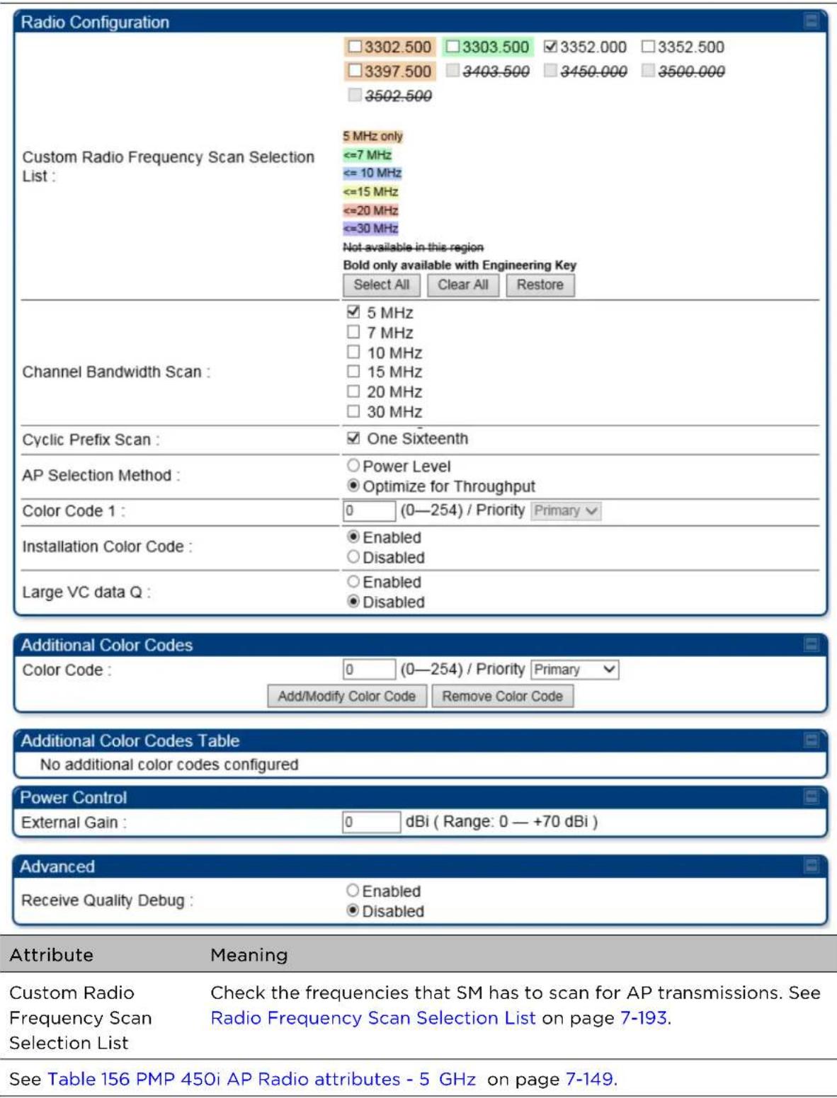
Radio page - PMP 450 SM 2.4 GHz
Table 169 PMP 450 SM Radio attributes - 2.4 GHz
| Radio Configuration | |
| Custom Radio Frequency Scan Selection List : | 2402.5 2405.0 2407.5 2410.0 2412.5 2415.0 |
| 2417.5 2420.0 2422.5 2425.0 2427.5 2430.0 | |
| 2432.5 2435.0 2437.5 ✓ 2440.0 2442.5 2445.0 | |
| 2447.5 2450.0 2452.5 2455.0 2457.5 2460.0 | |
| 2462.5 2465.0 2467.5 2470.0 2472.5 2475.0 | |
| 2477.5 2480.0 | |
| Channel Bandwidth Scan : | 5 MHz only |
| <= 10 MHz | |
| <=15 MHz | |
| <=20 MHz | |
| Not available in this region | |
| Select All Clear All Restore | |
| Cyclic Prefix : | 5 MHz |
| ✓ 10 MHz | |
| 15 MHz | |
| 20 MHz | |
| 30 MHz | |
| Additional Color Codes | |
| Color Code : | Power Level |
| Optimize for Throughput | |
| Color Code 1 : | 0 (0-254) / Priority Primary |
| Installation Color Code : | Enabled |
| Disabled | |
| Large VC data Q : | Enabled |
| Disabled | |
| Additional Color Codes Table | |
| Color Code | Priority |
| 10 | Primary |
| Power Control | |
| External Gain : | 0 dBi (Range: 0 - +40 dBi) |
| Enable Max Tx Power : | Enable |
| Disable | |
| Advanced | |
| Receive Quality Debug : | Enabled |
| Disabled | |
| Attribute | Meaning |
| Custom Radio Frequency Scan Selection List | Check the frequencies that SM has to scan for AP transmissions. See Radio Frequency Scan Selection List on page 7-193. |
See Table 156 PMP 450i AP Radio attributes - 5 GHz on page 7-149.
Radio page - PMP 450 SM 900 MHz
Table 170 PMP 450 SM Radio attributes -900 MHz
| Radio Configuration | ||||||
| 904.50 | 905.00 | 905.50 | 906.00 | 906.50 | 907.00 | |
| 907.50 | 908.00 | 908.50 | 909.00 | 909.50 | 910.00 | |
| 910.50 | 911.00 | 911.50 | 912.00 | 912.50 | 913.00 | |
| 913.50 | 914.00 | 914.50 | 915.00 | 915.50 | 916.00 | |
| 916.50 | 917.00 | 917.50 | 918.00 | 918.50 | 919.00 | |
| 919.50 | 920.00 | 920.50 | 921.00 | 921.50 | 922.00 | |
| Custom Radio Frequency Scan Selection List: | 922.50 | 923.00 | 923.50 | 924.00 | 924.50 | 924.75 |
| 925.00 | 925.50 | |||||
| 5 MHz only<=7 MHz<= 10 MHzNot available in this regionSelect All Clear All Restore | ||||||
| Channel Bandwidth Scan: | 5 MHz7 MHz10 MHz20 MHz | |||||
| Cyclic Prefix Scan: | One Sixteenth | |||||
| AP Selection Method: | Power LevelOptimize for Throughput | |||||
| Color Code 1: | 65 (0-254) / Priority Primary▼ | |||||
| Installation Color Code: | EnabledDisabled | |||||
| Large VC data Q: | EnabledDisabled | |||||
| Additional Color Codes | ||||||
| Color Code: | 5 (0-254) / Priority Tertiary▼Add/Modify Color Code Remove Color Code | |||||
| Additional Color Codes Table | ||||||
| Color Code | Priority | |||||
| 0 | Primary | |||||
| 1 | Secondary | |||||
| 5 | Tertiary | |||||
| Power Control | ||||||
| External Gain: | 0 dBi (Range: 0 - +40 dBi) | |||||
| Enable Max Tx Power: | EnableDisable | |||||
| Advanced | ||||||
| Receive Quality Debug: | EnabledDisabled | |||||
| Custom Radio Frequency Scan Selection List | See Table 156 PMP 450i AP Radio attributes - 5 GHz on page 7-149. | |||||
| Channel Bandwidth Scan | See Table 156 PMP 450i AP Radio attributes - 5 GHz on page 7-149. | |||||
| Cyclic Prefix Scan | ||||||
| AP Selection Method | ||||||
| Color Code 1 | ||||||
| Installation Color Code | ||||||
| Large VC data Queue | ||||||
| Color Code | ||||||
| External Gain | See Table 156 PMP 450i AP Radio attributes - 5 GHz on page 7-149 | |||||
| Enable Max Tx Power | See Table 156 PMP 450i AP Radio attributes - 5 GHz on page 7-149 | |||||
| Receive Quality Debug | See Table 156 PMP 450i AP Radio attributes - 5 GHz on page 7-149. | |||||

Note
The frequencies that a user can select are controlled by the country or a region and the Channel Bandwidth selected. There can be a case where a user adds a custom frequency (from the Custom Frequencies page on page 7-196) and cannot see it in the pull down menu.
Radio page - PTP 450 BHM 5 GHz
Table 171 PTP 450 BHM Radio attributes -5 GHz
| Radio Configuration | |
| Frequency Band : | 5.4 GHz ▼ |
| Frequency Carrier : | 5680.0 ▼ LBT Frequency Selected |
| Alternate Frequency Carrier 1 : | 5492.5 ▼ |
| Alternate Frequency Carrier 2 : | 5485.0 ▼ |
| Channel Bandwidth : | 20 MHz ▼ |
| Cyclic Prefix : | One Sixteenth ▼ |
| Color Code : | 5 (0—254) |
| Large VC data Q : | EnabledDisabled |
| Frame Configuration | ||
| Downlink Data : | 50 | % (Range: 15 — 85 %) |
| Power Control | ||
| Transmit Power : | 3 | dBm ( Range: -30 — +3 dBm ) (0 dBm V / 0 dBm H) |
| External Gain : | 17 | dB ( Range: 0 — +40 dB ) |
| Advanced | |||||
| Receive Quality Debug : | EnabledDisabled | ||||
| OFF | |||||
| Frame Alignment Legacy Mode : | Choose Legacy Mode setting from the table below based oncolocated radio's software revision and sync source: | ||||
| Sync Src. SWRev. | 13.4.1 orhigher | 12.0 to13.4(DFS on) | 12.0 to13.4(DFS off) | below12.0 | |
| Timing Port | OFF | OFF | OFF | OFF | |
| Power Port | OFF | OFF | ON (Mode1) | OFF | |
Attribute
Meaning
Refer Table 159 PTP 450i BHM Radio page attributes - 5 GHz on page 7-167 for all parameters details.
Radio page - PTP 450 BHS 5 GHz
Table 172 PTP 450 BHM Radio attributes -5 GHz
| Radio Configuration | |||||||
| 5.4 GHz | |||||||
| 5472.5 | 5475.0 | 5477.5 | 5480.0 | 5482.5 | 5485.0 | 5487.5 | |
| 5490.0 | 5492.5 | 5495.0 | 5497.5 | 5500.0 | 5502.5 | 5505.0 | |
| 5507.5 | 5510.0 | 5512.5 | 5515.0 | 5517.5 | 5520.0 | 5522.5 | |
| 5525.0 | 5527.5 | 5530.0 | 5532.5 | 5535.0 | 5537.5 | 5540.0 | |
| 5542.5 | 5545.0 | 5547.5 | 5550.0 | 5552.5 | 5555.0 | 5557.5 | |
| 5560.0 | 5562.5 | 5565.0 | 5567.5 | 5570.0 | 5572.5 | 5575.0 | |
| 5577.5 | 5580.0 | 5582.5 | 5585.0 | 5587.5 | 5590.0 | 5592.5 | |
| 5595.0 | 5597.5 | 5600.0 | 5602.5 | 5605.0 | 5607.5 | 5610.0 | |
| 5612.5 | 5615.0 | 5617.5 | 5620.0 | 5622.5 | 5625.0 | 5627.5 | |
| 5630.0 | 5632.5 | 5635.0 | 5637.5 | 5640.0 | 5642.5 | 5645.0 | |
| 5647.5 | 5650.0 | 5652.5 | 5655.0 | 5657.5 | 5660.0 | 5662.5 | |
| 5665.0 | 5667.5 | 5670.0 | 5672.5 | 5675.0 | 5677.5 | 5680.0 | |
| 5682.5 | 5685.0 | 5687.5 | 5690.0 | 5692.5 | 5695.0 | 5697.5 | |
| 5700.0 | 5702.5 | 5705.0 | 5707.5 | 5710.0 | 5712.5 | 5715.0 | |
| 5717.5 | 5720.0 | 5722.5 | |||||
| Custom Radio Frequency Scan Selection List: | |||||||
| 5.7 GHz | |||||||
| 5727.5 | 5730.0 | 5732.5 | 5735.0 | 5737.5 | 5740.0 | 5742.5 | |
| 5745.0 | 5747.5 | 5750.0 | 5752.5 | 5755.0 | 5757.5 | 5760.0 | |
| 5762.5 | 5765.0 | 5767.5 | 5770.0 | 5772.5 | 5775.0 | 5777.5 | |
| 5780.0 | 5782.5 | 5785.0 | 5787.5 | 5790.0 | 5792.5 | 5795.0 | |
| 5797.5 | 5800.0 | 5802.5 | 5805.0 | 5807.5 | 5810.0 | 5812.5 | |
| 5815.0 | 5817.5 | 5820.0 | 5822.5 | 5825.0 | 5827.5 | 5830.0 | |
| 5832.5 | 5835.0 | 5837.5 | 5840.0 | 5842.5 | 5845.0 | 5847.5 | |
| 5850.0 | 5852.5 | 5855.0 | 5857.5 | 5860.0 | 5862.5 | 5865.0 | |
| 5867.5 | 5870.0 | 5872.5 | 5875.0 | 5877.5 | 5880.0 | 5882.5 | |
| 5885.0 | 5887.5 | 5890.0 | 5892.5 | 5895.0 | 5897.5 | ||
| 5 MHz only<= 10 MHz<=15 MHz<=20 MHz<=30 MHzNot available in this regionSelect All Select All 5.4 Select All 5.7 Clear All Restore | |||||||


Attribute
Meaning
Refer Table 160 PTP 450i BHS Radio attributes - 5 GHz on page 7-170 for all parameters details.
Radio Frequency Scan Selection List
The SM or BHS scans complete spectrum as per Full Spectrum Band Scan feature. SMs or BHS first boot into the smallest selected channel bandwidth (10 MHz, if selected) and scan all selected frequencies across both the 5.4 GHz and 5.7 GHz frequency bands.
After this scan, if a wider channel bandwidth is selected (20 MHz), the SM/BHS automatically changes to 20 MHz channel bandwidth and then scans for APs/BHSs. After the SM/BHS finishes this final scan it will evaluate the best AP/BHM with which to register. If required for registration, the SM/BHS changes its channel bandwidth back to 10 MHz to match the best AP/BHM.
The SM/BHS will attempt to connect to an AP/BHM based on power level (which affects the modulation state), channel bandwidth (which affects throughput) and number of SM/BHS registrations to the AP/BHM (which affects system contention performance).
If it is desired to prioritize a certain AP/BHM over other available APs/BHMs, operators may use the Color Code Priority feature on the SM/BHS. Utilization of the Color Code feature on the AP/BHM is recommended to further constrain the AP selection.
If the SM does not find any suitable APs/BHMs for registration after scanning all channel bandwidths, the SM restarts the scanning process beginning with the smallest configured channel bandwidth.
Selecting multiple frequencies and multiple channel bandwidths impacts the SM/BHS scanning time. The biggest consumption of time is in the changing of the SM/BHS channel bandwidth setting.
The worst case scanning time is approximately two minutes after boot up (SM/BHS with all frequencies and channel bandwidths selected and registering to an AP/BHM at 10 MHz). If only one channel bandwidth is selected the time to scan all the available frequencies and register to an AP/BHM is approximately one minute after boot up.
Other scanning features such as Color Code, Installation Color Code, and RADIUS authentication are unaffected by the Full Band Scan feature.
Dedicated Multicast Virtual Circuit (VC)
A Multicast VC allows to configure multicast packets to be transmitted over a dedicated channel at a configurable rate of 1X, 2X, 4X or 8X. This feature is available only for the PMP 450 and PMP 450i and is not backward compatible with PMP 430 series of radios.
To configure Multicast VC, the AP must have this enabled. This can be enabled in the "Multicast Data Control" section (under Configuration > Radio page). The default value is "Disable". If set to the default value, all multicast packets are transmitted over the Broadcast VC data path. To enable, select the data rate that is desired for the Multicast VC Data Rate parameter and click Save Changes button. The radio requires no reboot after any changes to this parameter.
The multicast VC allows three different parameters to be configured on the AP. These can be changed on the fly and are saved on the flash memory.

Note
If the Multicast VC Data Rate is set to a modulation that the radio is not currently capable of or operates in non-permitted channel conditions, multicast data is sent but not received.
Ex: If Multicast VC Data Rate is set to 6x and the channel conditions only permit 4x mode of operation, then multicast data is sent at 6x modulation but the SM will not receive the data.

Note
The PMP 450 AP supports up to 119 VCs (instead of 238 VCs) when configured for 30 MHz channel bandwidth or 5 ms Frame Period. This limitation is not applicable for PMP 450i/450m Series.

Note
- Actual Multicast CIR honored by the AP = Configured Multicast CIR/ (Multicast Repeat Count + 1).
- Increasing the Multicast data rate has no impact on the Unicast data rate.
- For multicast and unicast traffic mix scenario examples, see Table 173.
Table 173 Example for mix of multicast and unicast traffic scenarios
| Repeat Count | Multicast Data Rate (Mbps) | Unicast Data Rate (Mbps) | Aggregate DL Data Rate (Mbps) |
| 0 10 40 50 | |||
| 1 5 40 45 |
2 3.33 40 43.33
The statistics have been added to the Data VC page (under Statistics > Data VC). The table displays the multicast row on the PMP 450 Platform Family AP. The SM displays the multicast row if it is a PMP 450 Platform Family.
Figure 152 Multicast VC statistics
| Subscriber | VC | CoS | Inbound Statistics | Outbound Statistics | Queue Overflow | High Priority Queue | ||||||||||||
| octets | ucast pkts | nucast pkts | discards | errors | QPSK frgmts | 16-QAM frgmts | 64-QAM frgmts | 256-QAM frgmts | octets | ucast pkts | nucast pkts | discards | errors | |||||
| Site Name - LUID: 002 | 018 | 00 | 2144887 | 6558 | 1121 | 0 | 0 | 5649 2098 | 3378 1656 | 2019 1607 | 1950 1199 | 2060928 | 7088 | 63 | 0 | 0 | 0 | 3972 |
| Multicast | 016 | 00 | NA | NA | NA | NA | NA | NA | NA | NA | NA | 0 | 0 | 0 | 0 | 0 | NA | NA |
| Broadcast | 012 | 00 | NA | NA | NA | NA | NA | NA | NA | NA | NA | 592059 | 16 | 8523 | 0 | 0 | NA | NA |
The AP and SM display Transmit and Receive Multicast Data Count (under the Statistics > Scheduler page), as shown in Figure 153.
Figure 153 Multicast scheduler statistics
| Radio Statistics | |
| Transmit Unicast Data Count : | 20778 |
| Transmit Broadcast Data Count : | 13 |
| Transmit Multicast Data Count : | 0 |
| Receive Unicast Data Count : | 20828 |
| Receive Broadcast Data Count : | 206042 |
| Receive Multicast Data Count : | 0 |
| Transmit Control Count : | 160 |
| Receive Control Count : | 39 |
| In Sync Count : | 62 |
| Out of Sync Count : | 0 |
| Overrun Count : | 0 |
| Underrun Count : | 0 |
| Receive Corrupt Data Count : | 0 |
| Receive Corrupt Control Data Count : | 0 |
| Receive Bad Broadcast Control Count : | 0 |
| Unsupported Feature Beacon Received : | 0 |
| Unknown Feature Beacon Received : | 0 |
| Old Version Beacon Received : | 0 |
| Wrong Frequency Beacon Received : | 0 |
| Non Lite Beacon Received : | 0 |
| Bad In Sync ID Received : | 0 |
| Rcv LT Start : | 0 |
| Rcv LT Start HS : | 0 |
| Rcv LT Result : | 0 |
| Xmt LT Result : | 0 |
| Frame Too Big : | 0 |
| Bad Acknowledgment : | 0 |
Custom Frequencies page
In addition to the Radio tab, AP/SM/BH has another tab called Custom Frequencies as shown in Table 174.
The custom frequency tab allows to configure custom frequency at 1 KHz raster. It means that the custom frequencies can be at granularity of 1 KHz e.g. 4910.123 MHz, 4922.333 MHz, 4933.421 MHz etc.

Note
Ensure that a customer frequency exists before using SNMP to set the radio to a Custom Frequency.
Table 174 450 Platform Family AP/SM/BH Custom Frequencies page - 5 GHz
| Custom Frequencies Configuration | |||
| Custom Frequency Configuration : | 4950.000 | MHz ( Range: 4902.500 — 4997.500 MHz ) | |
| Add Frequency | Remove Frequency | Add Default Frequencies | Remove All Custom Frequencies |
| Custom Frequencies | |
| Number of Custom Frequencies : | 12 |
| 4905.000 MHz | |
| 4910.000 MHz | |
| 4915.000 MHz | |
| 4920.000 MHz | |
| 4925.000 MHz | |
| 4930.000 MHz | |
| 4935.000 MHz | |
| 4940.000 MHz | |
| 4945.000 MHz | |
| 4950.000 MHz | |
| 4980.000 MHz | |
| 4990.001 MHz | |
| Attribute | Meaning |
| Custom Frequency Configuration | Custom frequencies with a channel raster of 1 KHz can be added from the available range by keying in the frequency and then clicking the Add Frequency button. Click Remove Frequency button to delete a specific frequency keyed in the text box.Click Default Frequencies button to add a pre-defined list of frequencies that can be used in this band. This list can be reduced or increased by manually removing or adding other custom frequencies. |
| Custom Frequencies | Displays the complete list of user configured custom frequencies. |
Table 175 PMP/PTP 450 SM/BH Custom Frequencies page - 3.65 GHz
| Custom Frequencies Configuration | ||
| Custom Frequency Configuration : | 0000.000 | MHz ( Range: 3552.500 — 3797.500 MHz ) |
| Add Frequency | Remove Frequency | Default Frequencies |
| Custom Frequencies | |
| Number of Custom Frequencies: | 27 |
| 3552.500 MHz | |
| 3554.500 MHz | |
| 3555.000 MHz | |
| 3564.100 MHz | |
| 3564.200 MHz | |
| 3564.500 MHz | |
| 3652.500 MHz | |
| 3655.000 MHz | |
| 3657.500 MHz | |
| 3660.000 MHz | |
| 3662.500 MHz | |
| 3665.000 MHz | |
| 3667.500 MHz | |
| 3670.000 MHz | |
| 3672.500 MHz | |
| 3675.000 MHz | |
| 3677.500 MHz | |
| 3680.000 MHz | |
| 3682.500 MHz | |
| 3685.000 MHz | |
| 3687.500 MHz | |
| 3690.000 MHz | |
| 3692.500 MHz | |
| 3695.000 MHz | |
| 3697.500 MHz | |
| 3700.000 MHz | |
| 3750.000 MHz | |
| Attribute | Meaning |
| Custom Frequency Configuration | Custom frequencies with a channel raster of 1 KHz can be added from the available range by keying in the frequency and then clicking the Add Frequency button. Click Remove Frequency button to delete a specific frequency keyed in the text box.Click Default Frequencies button to add a pre-defined list of frequencies that can be used in this band. This list can be reduced or increased by manually removing or adding other custom frequencies. |
| Custom Frequencies | Displays the complete list of user configured custom frequencies. |
Table 176 PMP/PTP 450 SM/BH Custom Frequencies page - 3.5 GHz
| Custom Frequencies Configuration | ||
| Custom Frequency Configuration : | 0000.000 | MHz ( Range: 3302.500 — 3597.500 MHz ) |
| Add Frequency | Remove Frequency | |
| Default Frequencies | ||
| Custom Frequencies | |
| Number of Custom Frequencies : | 66 |
| 3302.500 MHz | |
| 3302.501 MHz | |
| 3302.555 MHz | |
| 3302.600 MHz | |
| 3302.655 MHz | |
| 3305.000 MHz | |
| 3310.000 MHz | |
| 3315.000 MHz | |
| 3320.000 MHz | |
| 3325.000 MHz | |
| 3330.000 MHz | |
| 3335.000 MHz | |
| 3340.000 MHz | |
| 3345.000 MHz | |
| 3350.000 MHz | |
| 3355.000 MHz | |
| 3360.000 MHz | |
| 3365.000 MHz | |
| 3370.000 MHz | |
| 3375.000 MHz | |
| 3380.000 MHz | |
| 3385.000 MHz | |
| 3390.000 MHz | |
| 3395.000 MHz | |
| 3400.000 MHz | |
| 3405.000 MHz | |
| 3410.000 MHz | |
| Attribute | Meaning |
| Custom Frequency Configuration | Custom frequencies with a channel raster of 1 KHz can be added from the available range by keying in the frequency and then clicking the Add Frequency button. Click Remove Frequency button to delete a specific frequency keyed in the text box.Click Default Frequencies button to add a pre-defined list of frequencies that can be used in this band. This list can be reduced or increased by manually removing or adding other custom frequencies. |
DFS for 5 GHz Radios
Dynamic Frequency Selection (DFS) is a requirement in several countries and regions for 5 GHz unlicensed systems to detect radar systems and avoid co-channel operation. DFS and other regulatory requirements drive the settings for the following parameters, as discussed in this section:
- Country Code
- Primary Frequency
• Alternate 1 and Alternate 2 Frequencies
• External Antenna Gain
On the AP, the Home > DFS Status page shows current DFS status of all three frequencies and a DFS log of past DFS events.
Figure 154 AP DFS Status
| Current DFS Status | |
| Primary RF Carrier Frequency : | Active, 5485 Mhz, Normal Transmit |
| Alternate RF Carrier Frequency 1 : | Standby, 5570 Mhz, Available for use |
| Alternate RF Carrier Frequency 2 : | Standby, 5585 Mhz, Available for use |
| DFS Detections : | 0 |

DFS operation
The ODUs use region-specific DFS based on the Country Code selected on the module's Configuration, General page. By directing installers and technicians to set the Country Code correctly, the operator gains confidence the module is operating according to national or regional regulations without having to deal with the details for each region.
The details of DFS operation for each Country Code, including whether DFS is active on the AP, SM, and which DFS regulations apply is shown in Table 277 on page 10-59.
Contention slots
Contention slots are symbols at the end of the uplink subframe that are reserved for random access (network entry and bandwidth requests) and cannot be used for data transmission. These symbols form the contention space.
The frame is 2.5 ms or 5 ms long, and it is divided into a downlink subframe (data transmitted from the AP to the SM) and an uplink subframe (data transmitted from the SM to the AP).
Figure 155 Frame structure

The symbols in the uplink subframe can be scheduled or unscheduled. All scheduled symbols come before all unscheduled symbols. The number of scheduled and unscheduled symbols changes frame by frame depending on the amount of uplink requests received by the AP.
The contention slots number is selected by the operator and indicates the number of symbols that are reserved in the unscheduled portion of the uplink. The total number of unscheduled symbols in each frame is the sum of the contention slots and any additional symbol that was not used in uplink data transmission. This means that the unscheduled portion of the uplink can be as small as the number of contention slots, or as big as the whole uplink. This allows SMs in sectors with a small number of contention slots configured to still successfully transmit bandwidth requests using unused data slots.
Random access
When an SM needs to send an unscheduled message (for network entry or a bandwidth request), it randomly selects one symbol out of the unscheduled portion of the uplink subframe and uses that symbol for transmission. The higher the number of unscheduled symbols, the lower the probability two or more SMs will select the same symbol for transmission and their messages will collide. When two messages collide at the AP receiver, most likely neither will be decoded correctly, and both SMs need to start the random-access process one more time. If this happens frequently, the latency of the system increases.
A higher number of contention slots give higher probability that an SM's bandwidth request will be correctly received when the system is heavily loaded, but with the tradeoff that sector capacity is reduced, so there will be less capacity to handle the request. The sector capacity reduction is about 200 kbps for each contention slot configured in a 20 MHz channel at QPSK SISO modulation, for 2.5 ms frame sizes. The reduction in sector capacity is proportionally higher at MIMO modulations, as shown in the following table.
Table 177 Throughput penalty per modulation
| Modulation mode | Throughput penalty for each additional contention slot | |
| 2.5 ms frame | 5 ms frame | |
| QPSK SISO (1X) | 204 kbps | 102 kbps |
| QPSK MIMO (2X) 409 kbps 2 | 204 kbps | |
| 16-QAM MIMO (4X) | 819 kbps | 409 kbps |
| 64-QAM MIMO (6X) | 1.22 Mbps | 614 kbps |
| 256-QAM MIMO (8X) | 1.63 Mbps | 819 kbps |
Table 177 shows that the throughput penalty for each additional contention slot increases with modulation mode. The reason is that at higher modulation modes more fragments can be transmitted in a symbol. If additional symbols are reserved for random access, the number of fragments that cannot be sent in these symbols is higher at higher modulations, and therefore the throughput penalty is higher. However, the penalty expressed as a percentage of the throughput is the same for each modulation mode. For example, if a frame has 80 total symbols, each additional symbol reserved for random access reduces the sector throughput by 1.25%, regardless of the modulation mode.
Selection of contention slots parameter
The number of contention slots has to be selected according to the specific deployment parameters in each sector. If the number of contention slots is too small, then latency increases in high traffic periods. If the number of contention slots is too high, then the maximum capacity is unnecessarily reduced.
The two main contributing factors to the selection of the number of contention slots are the number of SMs in a sector, and the type of traffic in the sector.
Number of SMs in a sector
If the number of SMs in a sector is large, it is recommended to increase the number of contention slots, in order to reduce the probability of two or more requests colliding. The suggested contention slot settings as a function of the number of active Data channels in the sector are shown in Table 178.
Table 178 Contention slot settings
| Number of SMs | Recommended Number of Contention slots |
| 1 to 10 3 | |
| 11 to 50 4 | |
| 51 to 150 6 | |
| 151 and above 8 |
Type of traffic in a sector
Besides the number of SMs, the other main factor in contention slots selection is the type of traffic. If the sector experiences a lot of uplink traffic composed of small packets, for example in a sector that serves several VoIP streams, the average number of bandwidth requests transmitted by each SM is high. Another scenario with constant uplink traffic is video surveillance, which also generate a large number of uplink bandwidth requests.
In these cases, the probability of two or more SMs transmitting a request in the same symbol is high. When this happens, the latency of the system increases, and it is recommended to increase the number of contention slots from the number in Table 178. If an AP is experiencing latency or SM-servicing issues, increasing the number of contention slots may increase system performance, depending on traffic mix over time.
Recommendation on Contention Slots number selection
- Calculate the number of active SMs in the sector.
- Evaluate the traffic mix that is expected in the sector, more specifically the expected percentage of real-time traffic (ex. VoIP, gaming, video conferencing, and video surveillance).
- If the expected amount of real-time traffic is small, select the number of contention slots according to Table 178.
- If the expected amount of real-time traffic is large, select a number of contention slots larger than the number in Table 178.
- Monitor latency in your system. If the percentage of real-time traffic increases and the sector experiences increasing latency and SM-servicing issues, increase the number of contention slots from the current setting.
This is the reason why the maximum number of contention slots is 15, even if Table 2 shows 8 contention slots for more than 150 data channels. If the number of data channels is more than 150 and a significant portion of the traffic is real-time, the frequency with which bandwidth request messages are transmitted requires a higher number of contention slots, potentially as high as 15. A sector with a high number of video surveillance cameras would also require a larger number of contention slots to reduce the probability of collision between requests. - Monitor the percentage of BW requests successfully received and the UL frame utilization: if the frame utilization is high (close to 100%), then it is not recommended to change the number of contention slots, even if the percentage success rate of BW requests is low. However, if the percentage success rate of BW requests is low and the frame utilization is also low, then increasing the number of contention slots is recommended.
Cluster of APs
It is recommended to use care when changing the contention slots configuration of only some APs in a cluster, because changes affect the effective downlink/uplink ratio and can cause co-location issues.
In a typical cluster, each AP should be configured with the same number of contention slots to assure proper timing in the send and receive cycles. The number of contention slots is used by the frame calculator to define the downlink and uplink times, which should not overlap from one AP to another. However, if the traffic experienced by two APs in the same cluster is different (for example, one supports significantly more VoIP traffic), the number of contention slots selected for each AP may not be the same. For APs in a cluster of mismatched contention slots setting, it is recommended to use the frame calculator to verify that send and receive times do not overlap (see the Frame calculator for co-location).
Note: Change contention slot configuration in an operating, stable system cautiously and with a back-out plan. After changing a contention slot configuration, monitor the system closely for problems as well as improvements in system performance.
Frame calculator for co-location
The frame calculator is a tool available for the PMP 450 series systems, that calculates the length of the transmit and receive times, together with the number of downlink and uplink symbols, for a given set of configuration parameters. The frame calculator can be used to verify that co-location of APs using different contention slots settings does not create overlapping transmit and receive times.
Basic rules
For co-location of AP1 and AP2, we want to ensure that AP1 stops transmitting before AP2 starts receiving, and that AP2 stops transmitting before AP1 starts receiving.
These are the rules that have to be satisfied for a correct co-location of the two APs:
• AP1 Receive Start > AP2 Transmit End
• AP2 Receive Start > AP1 Transmit End
Steps for co-location
Let us assume that in a cluster of multiple APs with all the same settings, one AP's settings are modified with a different number of contention slots.
- Obtain all configuration settings for the APs that do not change parameters (duty cycle, contention slots, max distance)
- Input these configuration parameters into the OFDM Frame Calculator tool found under "Tools".
- Click "Calculate"
- Note the following values from the results:
AP Antenna Transmit End: ____
AP Antenna Receive Start:
- Access the AP that needs to have a different contention slots setting and use the frame calculator tool found under "Tools"
- Input the configuration parameters for this AP (same duty cycle and max distance as the other APs, different contention slots)
- Click "Calculate"
- Note the following values from the results:
AP Antenna Transmit End:
AP Antenna Receive Start:
- Check that the two following equations are both true:
AP1 Receive Start > AP2 Transmit End
AP2 Receive Start > AP1 Transmit End
- If one or both equations are not true, adjust the duty cycle until they become true (or the max distance if possible).
Example
Let us assume that all APs in a cluster have the same Max range settings, a 2.5 ms frame length and a 20 MHz channel BW, but the operator has fine-tuned the DL duty % per AP as follows:
AP1:
Max range: 2 miles Contention slots: 3 DL duty cycle = 75%
AP2:
Max range: 2 miles Contention slots: 3 DL duty cycle = 80%
Running the frame calculator as explained in the Steps for co-location, the AP1 Antenna Transmit End and Antenna Receive start times are:
• AP1 Antenna Transmit End = 1.6440 ms
• AP1 Antenna Receive Start = 1.7972 ms
AP2's Antenna Transmit End and Antenna Receive start times are:
• AP2 Antenna Transmit End = 1.7411 ms
• AP2 Antenna Receive Start = 1.8943 ms
The settings in AP1 in the cluster are now modified by changing the number of contention slots from 3 to 7, for example because this sector is constantly experiencing a higher volume of VoIP traffic.
Running the frame calculator again, the new AP1 Antenna Transmit End and Antenna Receive start times are:
• AP1 Antenna Transmit End = 1.5711 ms
• AP1 Antenna Receive Start = 1.7243 ms
The two equations above have to be checked for correct co-location:
• AP1 Antenna Receive Start > AP2 Antenna Transmit End → 1.7243 ms >1.7411 ms NOT OK
• AP2 Antenna Receive Start > AP1 Antenna Transmit End → 1.8943 ms >1.5711ms OK
The first of the two equations are not true. AP2 is still transmitting when AP1 has already started receiving. This creates interference at the AP1 receiver.
To avoid this interference scenario, the duty cycle of AP2 can be further adjusted slightly. For example, changing the duty cycle of AP2 from 80% to 79% changes the AP2 Antenna Transmit End and Antenna Receive start times as follows:
• AP2 Antenna Transmit End = 1.7168 ms
• AP2 Antenna Receive Start = 1.8700 ms
The two equations have to be checked again for co-location:
• AP1 Antenna Receive Start > AP2 Transmit End → 1.7243 ms >1.7168 ms OK
• AP2 Receive Start > AP1 Transmit End → 1.8700 ms >1.5711 ms OK
Now both equations are true and the APs can be co-located.
Cambium co-location tool
As an alternative to using the frame calculator on the AP GUI, cambium provides a colocation tool for these calculations. This tool is a free download available on the Cambium website:
https://support.cambiumnetworks.com/files/colocationtool/#r2
| PMP/PTP 450/450i/450m CO-LOCATION TOOL AND THROUGHPUT CALCULATOR | ||||||
| Release 15.1.1 | ||||||
| Device 1 Configuration | Device 2 Configuration | |||||
| Mode PMP Mode | Bandwidth (MHz) | PMP | ||||
| Channel Bandwidth (MHz) | 20 Channel | 20 | ||||
| Max Range (mi) | 2 | Max Range (mi) 2 | ||||
| Dowlink Data | 75% | Downlink Data | 80% | |||
| Contention slots | 3 | Contention Slots | 3 | |||
| Frame Period (ms) | 2.5 | Frame Period (ms) | 2.5 | |||
| Device 1 Timing (ms) | Device 2 Timing (ms) | |||||
| DL end | 1.644 | DL end | 1.741 | |||
| UL start | 1.797 | UL start | 1.894 | |||
| DL/UL symbols | 61/20 | DL/UL symbols | 65/16 | |||
| DL/UL/Total Throughput (Mbps) | 98.3/31.1/129.4 | DL/UL/Total Throughput (Mbps) | 104.9/24.6/129.5 | |||
| CHECKS | ||||||
| Device 1 DL end | 1.644 | < | Device 2 UL start | 1.894 | OK | |
| Device 2 DL end | 1.741 | < | Device 1 UL start | 1.797 | OK | |
| Device 2 Configuration | ||
| PMP |  | |
| 20 | ||
| Max Range (mi) 2 | ||
| Downlink Data | 80% | |
| Contention Slots | 3 | |
| Frame Period (ms) | 2.5 | |
| Device 2 Timing (ms) | ||
| DL end | 1.741 | |
| UL start | 1.894 | |
| DL/UL symbols | 65/16 | |
| DL/UL/Total Throughput (Mbps) | 104.9/24.6/129.5 | |
| CHECKS | |||||
| Device 1 DL end | 1.644 | < | Device 2 UL start | 1.894 | OK |
| Device 2 DL end | 1.741 | < | Device 1 UL start | 1.797 | OK |
MIMO-A mode of operation
450 Platform Family supports MIMO-B mode using the following modulation levels: QPSK, 16-QAM, 64-QAM and 256-QAM. System Release 13.2 introduces MIMO-A mode of operation using the same modulation levels as the MIMO-B mode. With MIMO-B, the radio sends different streams of data over the two antennas whereas with MIMO-A, the radio uses a scheme that tries to optimize coverage by transmitting the same data over both antennas. This redundancy improves the signal to noise ratio at the receiver making it more robust, at the cost of throughput.
In addition to introducing MIMO-A modes, improvements have been made to the existing rate adapt algorithm to switch between MIMO-A and MIMO-B seamlessly without any intervention or added configuration by the operator. The various modulation levels used by the 450 Platform Family are shown in Table 179.
Table 179 450 Platform Family Modulation levels
| Rate | MIMO-B | MIMO-A |
| QPSK 2X MIMO-B 1X MIMO-A | ||
| 16-QAM | 4X MIMO-B | 2X MIMO-A |
| 64-QAM | 6X MIMO-B | 3X MIMO-A |
| 256-QAM | 8X MIMO-B | 4X MIMO-A |
System Performance
For System Performance details of all the 450 Platform Family ODUs, refer to the tools listed below:
• Link Capacity Planner for PMP/PTP 450 and 450i:
https://support.cambiumnetworks.com/files/capacityplanner/
• LINKPlanner for PMP/PTP 450/450i and PMP 450m:
https://support.cambiumnetworks.com/files/linkplanner/
Table 180 Co-channel Interference per (CCI) MCS
| MCS of Victim | MCS of Interferer | Channel BW (MHz) | CCI |
| 1X (QPSK SISO) | 6X (64-QAM MIMO-B) | 5, 7, 10, 15, 20, 30, or 40 | 10 dB |
| 2X (16-QAM SISO) | 6X (64-QAM MIMO-B) | 5, 7, 10, 15, 20, 30, or 40 | 17 dB |
| 3X (64-QAM SISO) | 6X (64-QAM MIMO-B) | 5, 7, 10, 15, 20, 30, or 40 | 25 dB |
| 1X (QPSK MIMO-A) | 6X (64-QAM MIMO-B) | 5, 7, 10, 15, 20, 30, or 40 | 7 dB |
| 2X (16-QAM MIMO-A) | 6X (64-QAM MIMO-B) | 5, 7, 10, 15, 20, 30, or 40 | 14 dB |
| 3X (64-QAM MIMO-A) | 6X (64-QAM MIMO-B) | 5, 7, 10, 15, 20, 30, or 40 | 22 dB |
| 4X (256-QAM MIMO-A) | 6X (64-QAM MIMO-B) | 5, 7, 10, 15, 20, 30, or 40 | 30 dB |
| 2X (QPSK MIMO-B) | 6X (64-QAM MIMO-B) | 5, 7, 10, 15, 20, 30, or 40 | 10 dB |
| 4X (16-QAM MIMO-B) | 6X (64-QAM MIMO-B) | 5, 7, 10, 15, 20, 30, or 40 | 17 dB |
| 6X (64-QAM MIMO-B) | 6X (64-QAM MIMO-B) | 5, 7, 10, 15, 20, 30, or 40 | 25 dB |
| 8X (256-QAM MIMO-B) | 6X (64-QAM MIMO-B) | 5, 7, 10, 15, 20, 30, or 40 | 33 dB |
Table 181 Adjacent Channel Interference (ACI) per MCS
| MCS of Victim | MCS of Interferer | Channel BW (MHz) | ACI | Guard Band |
| 1X (QPSK SISO) | 6X (64-QAM MIMO-B) | 5, 7, 10, 15, 20, 30, or 40 | -16 dB | None |
| 2X (16-QAM SISO) | 6X (64-QAM MIMO-B) | 5, 7, 10, 15, 20, 30, or 40 | -16 dB | None |
| 3X (64-QAM SISO) | 6X (64-QAM MIMO-B) | 5, 7, 10, 15, 20, 30, or 40 | -16 dB | None |
| 1X (QPSK MIMO-A) | 6X (64-QAM MIMO-B) | 5, 7, 10, 15, 20, 30, or 40 | -13 dB | None |
| 2X (16-QAM MIMO-A) | 6X (64-QAM MIMO-B) | 5, 7, 10, 15, 20, 30, or 40 | -13 dB | None |
| 3X (64-QAM MIMO-A) | 6X (64-QAM MIMO-B) | 5, 7, 10, 15, 20, 30, or 40 | -13 dB | None |
| 4X (256-QAM MIMO-A) | 6X (64-QAM MIMO-B) | 5, 7, 10, 15, 20, 30, or 40 | -10 dB | None |
| 2X (QPSK MIMO-B) | 6X (64-QAM MIMO-B) | 5, 7, 10, 15, 20, 30, or 40 | -16 dB | None |
| 4X (16-QAM MIMO-B) | 6X (64-QAM MIMO-B) | 5, 7, 10, 15, 20, 30, or 40 | -16 dB | None |
| 6X (64-QAM MIMO-B) | 6X (64-QAM MIMO-B) | 5, 7, 10, 15, 20, 30, or 40 | -16 dB | None |
| 8X (256-QAM MIMO-B) | 6X (64-QAM MIMO-B) | 5, 7, 10, 15, 20, 30, or 40 | -10 dB | None |
Guard Band
When synchronized, no Guard Bands are needed for the 450°, 450i, and 450m Series.
* For PMP 450 AP (3.6 GHz) and 450 series APs with 450b SM (5 GHz) connected, Configuration -> Radio -> Power Control -> Adjacent Channel Support must be enabled.
Adjacent Channel Support :
- Enabled - Disabled
Improved PPS performance of 450 Platform Family
The 450m, 450i, and 450b Series provides improved packets per second (PPS) performance compared to 450 Series.
Through hardware and software enhancements, the PPS performance of the PMP 450i Series AP and PMP 450b SM has been improved to 40k packets/second, measured through a standard RFC2544 test using 64 bytes packets. With this enhancement, operators are able to provide higher bandwidth including better VoIP and video services to end customers using existing SM deployments.
PMP 450m supports 100k packets/second.
Setting up SNMP agent
Operators may use SNMP commands to set configuration parameters and retrieve data from the AP and SM modules. Also, if enabled, when an event occurs, the SNMP agent on the 450 Platform Family sends a trap to whatever SNMP trap receivers configured in the management network.
- SNMPv2c
- SNMPv3
Configuring SM/BHS's IP over-the-air access
To access the SM/BHS management interface from a device situated above the AP, the SM/BHS's Network Accessibility parameter (under the web GUI at Configuration > IP) may be set to Public.
Table 182 LAN1 Network Interface Configuration tab of IP page attributes
| LAN1 Network Interface Configuration | ||
| IP Address: | 169.254.1.1 | |
| Network Accessibility: | ○ Public○ Local | |
| Subnet Mask: | 255.255.255.0 | |
| Gateway IP Address: | 169.254.0.0 | |
| DHCP state: | ○ Enabled○ Disabled | |
| DHCP DNS IP Address: | ○ Obtain Automatically○ Set Manually | |
| Preferred DNS Server: | 10.120.10.12 | |
| Alternate DNS Server: | 10.120.10.13 | |
| Domain Name: | example.com | |
| Attribute | Meaning |
| IP Address | Internet Protocol (IP) address. This address is used by family of Internet protocols to uniquely identify this unit on a network. |
| Network Accessibility | Specify whether the IP address of the SM/BHS must be visible to only a device connected to the SM/BHS by Ethernet (Local) or be visible to the AP/BHM as well (Public). |
| Subnet Mask | If Static IP is set as the Connection Type of the WAN interface, then this parameter configures the subnet mask of the SM/BHS for RF management traffic. |
| Gateway IP Address | If Static IP is set as the Connection Type of the WAN interface, then this parameter configures the gateway IP address for the SM/BHS for RF management traffic. |
| DHCP state | If Enabled is selected, the DHCP server automatically assigns the IP configuration (IP address, subnet mask, and gateway IP address) and the values of those individual parameters (above) are not used. The setting of this DHCP state parameter is also viewable (read only), in the Network Interface tab of the Home page. |
| DNS IP Address | Canopy devices allow for configuration of a preferred and alternate DNS server IP address either automatically or manually. Devices must set DNS server IP address manually when DHCP is disabled for the management interface of the device. The default DNS IP addresses are 0.0.0.0 when configured manually. |
| Preferred DNS Server | The first address used for DNS resolution. |
| Alternate DNS Server | If the Preferred DNS server cannot be reached, the Alternate DNS Server is used. |
| Domain Name | The operator's management domain name may be configured for DNS. The domain name configuration can be used for configuration of the servers in the operator's network. The default domain name is example.com, and is only used if configured as such. |
Configuring SNMP
The SNMP page configuration is explained below.

Note
The SNMP page for AP, SM, BHM and BHS has the same parameter attributes.
SNMP page - AP/SM/BHM/BHS
The SNMP page is explained in Table 183.
Table 183 SNMP page attributes
| SNMPv2c Settings | |
| SNMP Community String 1: | Canopy |
| SNMP Community String 1 Permissions: | Read OnlyRead / Write |
| SNMP Community String 2 (Read Only): | Canopyro |
| SNMPv3 Settings | |
| Engine ID: | 800000a1030a003e4586f0Use Default Engine ID |
| SNMPv3 Security Level: | auth,prv▼ |
| SNMPv3 Authentication Protocol: | md5▼ |
| SNMPv3 Privacy Protocol: | cbc-des▼ |
| SNMPv3 Read-Only User: | Username CanopyroAuthorization Key**********Privacy Key********** |
| SNMPv3 Read/Write User: | Enable R/W UserDisable R/W UserUsername CanopyAuthorization Key**********Privacy Key********** |
| Additional SNMPv3 User1: | UsernameEnable UserDisable UserAuthorization KeyPrivacy KeyReadWrite UserReadOnly User |
| Additional SNMPv3 User2: | UsernameEnable UserDisable UserAuthorization KeyPrivacy KeyReadWrite UserReadOnly User |
| Additional SNMPv3 User3: | UsernameEnable UserDisable UserAuthorization KeyPrivacy KeyReadWrite UserReadOnly User |
| SNMPv3 Trap Configuration: | Disabled▼ |
SNMP Accessing Addresses
| Accessing IP / Subnet Mask 1 : | 0.0.0.0 | / 0 | |
| Accessing IP / Subnet Mask 2 : | 0.0.0.0 | / 0 | |
| Accessing IP / Subnet Mask 3 : | 0.0.0.0 | / 0 | |
| Accessing IP / Subnet Mask 4 : | 0.0.0.0 | / 0 | |
| Accessing IP / Subnet Mask 5 : | 0.0.0.0 | / 0 | |
| Accessing IP / Subnet Mask 6 : | 0.0.0.0 | / 0 | |
| Accessing IP / Subnet Mask 7 : | 0.0.0.0 | / 0 | |
| Accessing IP / Subnet Mask 8 : | 0.0.0.0 | / 0 | |
| Accessing IP / Subnet Mask 9 : | 0.0.0.0 | / 0 | |
| Accessing IP / Subnet Mask 10 : | 0.0.0.0 | / 0 |
Trap Addresses
| SNMP Trap Server DNS Usage : | Append DNS Domain NameDisable DNS Domain Name | |
| Trap Address 1 : | 0.0.0.0 | |
| Trap Address 2 : | 0.0.0.0 | |
| Trap Address 3 : | 0.0.0.0 | |
| Trap Address 4 : | 0.0.0.0 | |
| Trap Address 5 : | 0.0.0.0 | |
| Trap Address 6 : | 0.0.0.0 | |
| Trap Address 7 : | 0.0.0.0 | |
| Trap Address 8 : | 0.0.0.0 | |
| Trap Address 9 : | 0.0.0.0 | |
| Trap Address 10 : | 0.0.0.0 | |
Trap Enable
| Sync Status : | EnabledDisabled |
| Session Status : | EnabledDisabled |
Site Information
| Site Information Viewable to Guest Users:EnabledDisabled | |
| Site Name: | .64 AP 5.7 MIMO |
| Site Contact: | Jamus Jegier |
| Site Location: | Canopy FW Screen Room (W4+1) |
| Attribute | Meaning | |
| SNMP Community String 1 | Specify a control string that can allow a Network Management Station (NMS) to access SNMP information. No spaces are allowed in this string. The default string is Canopy. | |
| SNMP Community String 1 Permissions | You can designate the SNMP Community String 1 to be the password for WM, for example, to have Read / Write access to the module via SNMP or for all SNMP access to the module to be Read Only. | |
| SNMP Community String 2 (Read Only) | Specify an additional control string that can allow a Network Management Station (NMS) to read SNMP information. No spaces are allowed in this string. The default string is Canopyro. This password will never authenticate a user or an NMS to read/write access. | |
| The Community String value is clear text and is readable by a packet monitor. Additional security derives from the configuration of the Accessing Subnet, Trap Address, and Permission parameters. | ||
| Engine ID The Engine Level | ID may be between 5 and 32 hex characters. The hex character input is driven by RFC 3411 recommendations on the Engine ID. The default Engine ID is the MAC address of the device | |
| SNMPv3 Security Level | Specify security model where users are defined and authenticated before granting access to any SNMP service. Each device can configure the security level of SNMPv3 to No authentication/No privacy, Authentication/No privacy, or Authentication/Privacy. | |
| SNMPv3 Authentication Protocol | Currently, the SNMPv3 authentication protocol MD5 is supported. | |
| SNMPv3 Privacy Protocol | Currently, the SNMPv3 privacy protocol CBC-DES is supported. | |
| SNMPv3 Read-Only User | This field allows for a read-only user per devices. The default values for the Read-Only users is:Username = CanopyroAuthentication Password = authCanopyroPrivacy Password = privacyCanopyro | |
| SNMPv3 Read/Write User | Read-write user by default is disabled. The default values for the Read/Write users is:Username = CanopyAuthentication Password = authCanopyPrivacy Password = privacyCanopy | |
| Additional SNMP v3 User 1 | This field allows to configure the Additional SNMP v3 User 1. The configurations include:Enable/Disable User: These fields allow to enable or disable the user using the Enable User or Disable User radio buttons.Authorizaton Key: This field allows to configure an authorization key for the user.Privacy Key: This field allows to configure a privacy key for the user. | |
 | Note:Set SNMP v3 Security Level field to :auth,priv to enable the Authorization Key and Privacy Key fields. | |
| Enabled User can be set with following privacy settings:ReadWrite UserReadOnly User | ||
| Additional SNMP v3User 2 | This field allows to configure the Additional SNMP v3 User 2.The configurations include:Enable/Disable User: These fields allow to enable or disable the user using the Enable User or Disable User radio buttons.Authorizaton Key: This field allows to configure an authorization key for the user.Privacy Key: This field allows to configure a privacy key for the user.[IMAGE]Set SNMP v3 Security Level field to :auth,priv to enable the Authorization Key and Privacy Key fields.Enabled User can be set with following Privacy settings:ReadWrite UserReadOnly User | |
| Additional SNMP v3User 3 | This field allows to configure the Additional SNMP v3 User 3.The configurations include:Enable/Disable User: These fields allow to enable or disable the user using the Enable User or Disable User radio buttons.Authorizaton Key: This field allows to configure an authorization key for the user.Privacy Key: This field allows to configure a privacy key for the user.[IMAGE]Set SNMP v3 Security Level field to :auth,priv to enable the Authorization Key and Privacy Key fields.Enabled User can be set with following Privacy settings:ReadWrite UserReadOnly User | |
| SNMPv3 TrapConfiguration | When enabling transmission of SNMPv3 traps the read-only or read-write user credentials must be used and selected properly in order for the SNMP manager to correctly interpret the traps. By default transmission of SNMPv3 traps is disabled and all traps sent from the radios are in SNMPv2c format. | |
| Accessing IP /Subnet Mask 1 to 10 | Specify the addresses that are allowed to send SNMP requests to this AP. The NMS has an address that is among these addresses (this subnet). You must enter bothThe network IP address in the form xxx.xxx.xxx.xxxThe CIDR (Classless Interdomain Routing) prefix length in the form /xxFor example:the /16 in 198.32.0.0/16 specifies a subnet mask of 255.255.0.0 (the first 16 bits in the address range are identical among all members of the subnet).192.168.102.0 specifies that any device whose IP address is in the range 192.168.102.0 to 192.168.102.254 can send SNMP requests to the AP, presuming that the device supplies the correct Community String value.The default treatment is to allow all networks access. For more information on CIDR, execute an Internet search on “Classless Interdomain Routing.” You are allowed to specify as many as 10 different accessing IP address, subnet mask combinations.RECOMMENDATION:The subscriber can access the SM/BHS by changing the subscriber device to the accessing subnet. This hazard exists because the Community String and Accessing Subnet are both visible parameters. To avoid this hazard, configure the SM/BHS to filter (block) SNMP requests. | |
| SNMP Trap Server DNS Usage | The management DNS domain name may be toggled such that the name of the trap server only needs to be specified and the DNS domain name is automatically appended to that name. The default SNMP trap server addresses for all 10 available servers is 0.0.0.0 with the appending of the DNS domain name disabled. | |
| Trap Address 1 to 10 | Specify ten or fewer IP addresses (xxx.xxx.xxx.xxx) or DNS names to which SNMP traps must be sent. Traps inform Wireless Manager or an NMS that something has occurred. For example, trap information is sent• after a reboot of the module.• when an NMS attempts to access agent information but either• supplied an inappropriate community string or SNMP version number.• is associated with a subnet to which access is disallowed. | |
| Trap Enable, Sync Status | If the sync status traps (sync lost and sync regained) have to be sent to Wireless Manager or an NMS, select Enabled. If these traps have to be suppressed, select Disabled. | |
| Trap Enable, Session Status | If you want session status traps sent to Wireless Manager or an NMS, select Enabled. | |
| Site Information Viewable to Guest Users | Operators can enable or disable site information from appearing when a user is in GUEST account mode. | |
| Site Name Specify a string to associate with the physical module. This parameter is written into the sysName SNMP MIB-II object and can be polled by Wireless Manager or an NMS. The buffer size for this field is 128 characters. | ||
| Site Contact | Enter contact information for the module administrator. This parameter is written into the sysContact SNMP MIB-II object and can be polled by Wireless Manager or an NMS. The buffer size for this field is 128 characters. | |
| Site Location | Enter information about the physical location of the module. This parameter is written into the sysLocation SNMP MIB-II object and can be polled by Wireless Manager or an NMS. The buffer size for this field is 128 characters. | |
Configuring syslog
450 Platform Family includes:
- Syslog event logging
- Configuring system logging
Syslog event logging
Following events are logged in syslog as explained in Table 184.
Table 184 Syslog parameters
| Attribute | Meaning | |
| Timestamp | All syslog messages captured from the radio have a timestamp. | |
| Configuration Changes | This includes any device setting that has changed and includes the old or new parameter value, including the device reboots. | |
| User Login and Logout | Syslog records each user login and logout, with username. | |
| Add or Delete of user accounts through GUI and SNMP | Syslog captures any user accounts that are added or deleted. | |
| Spectrum Analysis | Syslog records a message every time Spectrum Analysis runs. | |
 | NoteSince the AP/BHM must be set to a SM/BHS for Spectrum Analysis, syslog messages are not reported from the radio until the scan is done and the radio mode is switched back to AP/BHM. | |
| Link Test | Syslog records a message every time a Link Test is run. | |
| Clear Statistics | Syslog sends a message when Statistics are cleared. This is done individually for each statistics page that is cleared. | |
| SM Register or De-register | Syslog records a message when a SM registers or deregisters. | |
| BHS Connect or Disconnect | Syslog records a message when a BHS connects or disconnects. | |
Configuring system logging
To configure system logging, select the menu option Configuration > Syslog.
Syslog page of AP/BHM
The Syslog Configuration page for AP/BHM is shown in Table 185.
Table 185 Syslog Configuration attributes - AP
| Syslog Server Configuration | |
| Syslog DNS Server Usage: | ○ Append DNS Domain Name ● Disable DNS Domain Name |
| Syslog Server: | 0.0.0.0 |
| Syslog Server Port: | 514 Default port number is 514 |
| Syslog Transmission | |
| AP Syslog Transmit: | ○ Enabled ● Disabled |
| SM Syslog Transmit: | ○ Enabled ● Disabled |
| Syslog Level | |
| Syslog Minimum Level: | info |
| Attribute | Meaning |
| Syslog DNS Server Usage | To configure the AP/BHM to append or not append the DNS server name to the syslog server name. |
| Syslog Server | The dotted decimal or DNS name of the syslog server address. |
| Syslog Server Port | The syslog server port (default 514) to which syslog messaging is sent. |
| AP Syslog Transmit Or BHM Syslog Transmit | When enabled, syslog messages are sent from the AP/BHM. |
| SM Syslog Transmit Or BHS Syslog Transmit | When enabled, syslog messages are sent from all the registered SMs/BHS, unless they are individually set to override this. |
| Syslog Minimum Level | This provides a selection for the minimum syslog message severity that is sent to the syslog server. Values range from fatal (highest severity and least verbose) to info (lowest severity, maximum verbosity). For example: If the Syslog Minimum Level is set to notice, then only messages with severity notice and above are sent. |
Syslog page of SM
To configure system logging, select the menu option Configuration > Syslog. The Syslog Configuration page is shown in Table 186.
Table 186 Syslog Configuration attributes - SM
| Syslog Server Configuration | ||
| Syslog Configuration Source : | ● AP preferred, use local when AP configuration unavailable○ Local only | |
| Syslog DNS Server Usage : | ○ Append DNS Domain Name○ Disable DNS Domain Name | |
| Syslog Server : | 0.0.0.0 | |
| Syslog Server Port : | 514 | Default port number is 514 |
| Syslog Transmission | |
| Syslog Transmission : | Obtain from AP, default disabled ▼ |
| Syslog Level | |
| Syslog Minimum Level Source : | ● AP preferred, use local when AP configuration unavailable○ Local only |
| Syslog Minimum Level : | info ▼ |
| Attribute | Meaning |
| SyslogConfigurationSource | This control determines whether the SM will attempt to use the syslog server definition from the AP, or whether it will use a local server definition.When set to AP preferred, use local when AP configuration unavailable, and if the SM can register with an AP, then it uses the syslog server defined on that AP. If the SM cannot register then it will syslog to its locally defined syslog server through its wired connection, if any.When set to Local only the SM ignores the AP's definition of the syslog server and allows the syslog server to be configured individually for each SM. |
| Syslog DNS Server Usage | To configure the SM to append or not the DNS server name to the syslog server name. |
| Syslog Server | The dotted decimal or DNS name of the syslog server address. |
| Syslog Server Port | The syslog server port (default 514) to which syslog messaging is sent. |
| SyslogTransmission | Controls the SMs ability to transmit syslog messages. When set to “Learn from AP” the AP will control whether this SM transmits syslog messages. When set to “enable” or “disable” the SM will control whether it sends syslog messages. This allows an operator to override the AP settings for individual SMs in a sector. |
| Syslog MinimumLevel Source | This control determines whether the SM attempts to use the minimum syslog level defined by the AP, or whether it uses a local defined value using the “Syslog Minimum Level” parameter.When set to “AP preferred, use local when AP configuration unavailable”, and if the SM can register with an AP, then it uses the Syslog Minimum Level defined on that AP. If the SM cannot register then it uses its own Syslog Minimum Level setting.When set to “Local only” the SM will always use its own Syslog Minimum Level setting and ignores the AP's setting. |
| Syslog Minimum Level | This provides a selection for the minimum syslog message severity that is sent to the syslog server. Values range from fatal (highest severity and least verbose) to info (lowest severity, maximum verbosity).For example: If the Syslog Minimum Level is set to notice, then only messages with severity notice and above are sent. |
Syslog page of BHS
The Syslog Configuration page is shown in Table 187.
Table 187 Syslog Configuration attributes - BHS
| Syslog Server Configuration | ||
| Syslog Configuration Source : | ● BHM preferred, use local when BHM configuration unavailable○ Local only | |
| Syslog DNS Server Usage : | ○ Append DNS Domain Name○ Disable DNS Domain Name | |
| Syslog Server : | 0.0.0.0 | |
| Syslog Server Port : | 514 | Default port number is 514 |
| Syslog Transmission | |
| Syslog Transmission : | obtain-from-BHM-default-disabled▼ |
| Syslog Level | |
| Syslog Minimum Level Source : | ● BHM preferred, use local when BHM configuration unavailable○ Local only |
| Syslog Minimum Level : | info ▼ |
| Attribute | Meaning |
| SyslogConfigurationSource | This control determines whether the BHS will attempt to use the syslog server definition from the BHM, or whether it will use a local server definition.When set to BHM preferred, use local when BHM configuration unavailable, and if the BHS can register with a BHM, then it uses the syslog server defined on that BHM. If the BHS cannot register then it will syslog to its locally defined syslog server through its wired connection, if any.When set to Local only the BHS ignores the BHM's definition of the syslog server and allows the syslog server to be configured individually for each BHS. |
| Syslog DNS Server Usage | To configure the BHS to append or not to append the DNS server name to the syslog server name. |
| Syslog Server | The dotted decimal or DNS name of the syslog server address. |
| Syslog Server Port | The syslog server port (default 514) to which syslog messaging is sent. |
| Syslog Transmission | Controls the BHSs ability to transmit syslog messages. When set to Learn from BHM the BHM will control whether this BHS transmits syslog messages. When set to enable or disable the BHS will control whether it sends syslog messages. This allows an operator to override the BHM settings for individual BHSs in a sector. |
| Syslog Minimum Level Source | This control determines whether the BHS attempts to use the minimum syslog level defined by the BHM, or whether it uses a local defined value using the Syslog Minimum Level parameter.When set to BHM preferred, use local when BHM configuration unavailable, and if the BHS can register with a BHM, then it uses the Syslog Minimum Level defined on that BHM. If the BHS cannot register then it uses its own Syslog Minimum Level setting.When set to Local only the BHS will always use its own Syslog Minimum Level setting and ignores the BHM's setting. |
| Syslog Minimum Level | This provides a selection for the minimum syslog message severity that is sent to the syslog server. Values range from fatal (highest severity and least verbose) to info (lowest severity, maximum verbosity).For example: If the Syslog Minimum Level is set to notice, then only messages with severity notice and above are sent. |
Configuring remote access
Accessing SM/BHS over-the-air by Web Proxy
The SM/BHS may be accessed via the AP/BHM management GUI by navigating to Home > Session Status (or Home > Remote Subscribers for AP only) and clicking on the SM's hyperlink.
For example, to access one of the SMs, click LUID: 002 - [0a-00-3e-37-b9-fd], as shown in Figure 156.
Figure 156 AP Session Status page
![General Status Session Status Remote Subscribers Event Log Network Interface Layer 2 Neighbors Home → Session Status 5.4GHz MIMO OFDM - Access Point - 0a-00-3e-a1-35-75 Session Status Configuration Show Idle Sessions : Enabled Disabled Session List Tools Last Session Counter Reset : None Reset Session Counters Last Time Idle SMs Removed : None Remove Idle SMs Session Status List Data : SessionStatus.xml Device Session Power Configuration Subscriber Hardware Software Version FPGA Version LUID: 002 - [0a-00-3e-a0-a0-66] No Site Name PMP 450 CANOPY 14.1.1 110615 (DES, Sched, US/ETSI) P](/content/2026/05/943724/images/20f307fbb4de2fa0686b6aadc171e71790dc2a3c4e4b3bc11614a401f320116f.jpg)
The SessionStatus.xml hyper link allows user to export all displayed SM data in Session Status table into an xml file.
To access any one of the SMs, click 450 Platform Family - SM hyperlink, as shown in Figure 157.
Figure 157 AP Remote Subscribers page
Home → Remote Subscribers
5.4GHz MIMO OFDM - Access Point - 0a-00-3e-bb-00-fb
![Remote Subscriber Modules 01. Site Name - [0a-00-3e-bb-01-04] - LUID: 002](/content/2026/05/943724/images/1f558df5b1eea08e087ccae992ab4cf2bd09dbaefeb1c1106db345b3457c233d.jpg)
Monitoring the Link
Link monitoring procedure
After configuring the link, either an operator in the network office or the SM/BHS INSTALLER user in the field (if read access to the AP/BHM is available to the INSTALLER) must perform the following procedure. Who is authorized and able to do this depends on local operator password policy, management VLAN setup and operational practices.
To monitor the link for performance, follow these instructions:
Procedure 22 Monitoring the AP-SM link
1 Access the web interface of the AP/BHM
2 In the left-side menu of the AP/BHM interface, select Home.
3 Click the Session Status tab.
Figure 158 Session Status page
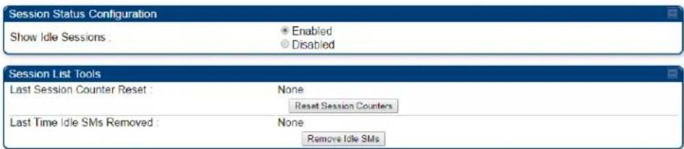
![Session Status List Data SessionStatus xml Device Session Power Configuration Subscriber Hardware Software Version FPGA Version State LUID 002 - [0a-00-3e-b2-c6-aa] PMP 450 CANOPY 15.0 061716 (DES, Sched, US/ETSI) P11 IN SESSION (Encrypt Disabled) LUID 003 - [0a-00-3e-b2-c6-9f] PMP 450 CANOPY 15.0 061716 (DES, Sched, US/ETSI) P11 IN SESSION (Encrypt Disabled) LUID 004 - [0a-00-3e-b2-c5-f1] PMP 450 CANOPY 15.0 061716 (DES, Sched, US/ETSI) P11 IN SESSION (Encrypt Disabled) LUID 005 - [0a-00-3e-b2-b2-6c] PMP 450 CANOPY 15.0 061716 (DES, Sched, US/ETSI) P11 IN SESSION (Encrypt Disabled) LUID 006 - [0a-00-3e-b2-b3-fb] PMP 450 CANOPY 15.0 061716 (DES, Sched, US/ETSI) P11 IN SESSION (Encrypt Disabled) LUID 007 - [0a-00-3e-b2-c7-14] PMP 450 CANOPY 15.0 061716 (DES, Sched, US/ETSI) P11 IN SESSION (Encrypt Disabled)](/content/2026/05/943724/images/dc2f854441cb9249cb3da70b28c3917a96f22fb62906826dd71d640218784c39.jpg)
4 The Device tab of Session Status List display all displayed SMs - MAC address, PMP/PTP Hardware, Software Version, FPGA Version and State
5 Click Session Count tab of Session Status List to display values for Session Count, Reg Count, and Re-Reg Count.
- Session Count: This field displays how many sessions the SM/BHS has had with the AP/BHM. Typically, this is the sum of Reg Count and Re-Reg Count. However, the result of internal calculation may display here as a value that slightly differs from the sum.
- Reg Count: When a SM/BHS makes a Registration Request, the AP/BHM checks its local session database to see whether it was registered earlier. If the AP/BHM concludes that the SM/BHS is not currently in session database and it is valid Registration Request, then the request increments the value of this field.
- Re-Reg Count: When a SM/BHS makes a Registration Request, the AP/BHM checks its local session database to see whether it was registered earlier. If the AP/BHM concludes that the SM/BHS is currently in session database, then the request increments the value of this field.
• Typically, a Re-Reg is the case where both
o SM/BHS attempts to reregister for having lost communication with the AP/BHM.
o AP/BHM has not yet observed the link to the SM/BHS as being down.
See Session tab on page 9-26
6 Click Power tab of Session Status list to display Downlink Rate, AP Rx Power (dBm), Signal Strength Radio (dB) for Uplink and Signal to Noise Radio (dB) for Uplink.
See Power tab on page 9-28
7 Click Configuration tab of Session Status list to get QoS configuration details:
• Sustained Data Rate (kbps)
- Burst Allocation (kbit)
• Max Burst Rate (kbit)
- Low Priority CIR (kbps)
See
Configuration tab on page 9-30
8 Briefly monitor these values, occasionally refreshing this page by clicking another tab and then the Session Status tab again.
9 If these values are low (for example, 1, 1, and 0, respectively, meaning that the SM/BHS registered and started a stable session once) and are not changing:
- Consider the installation successful.
• Monitor these values from the network office over the next several hours and days.
If these values are greater than 1, 1, and 0, or they increase while you are monitoring them, troubleshoot the link. (For example, Use Receive Power Level for aiming and then use Link Tests to confirm alignment).
Refer Viewing Session Status on page 9-24 for more details.
Exporting Session Status page of AP/BHM
The SessionStatus.xml hyper link allows user to export all displayed SMs or BHS data in Session Status table into an xml file.
Figure 159 Exporting Session Status page of PMP 450m AP
![Session Status List Data : SessionStatus.xml Device Session Power Configuration Subscriber Hardware Software Version FPGA Version State LUID: 002 - [0a-00-3e-b2-c6-aa] PMP 450 CANOPY 15.0 061716 (DES, Sched, US/ETSI) P11 IN SESSION (Encrypt Disabled)](/content/2026/05/943724/images/f479530294b8c68100e8d0d4de92647d6843894c2f262083f6b7c44781042c3c.jpg)
In case of PMP, if the session status page does not list any SM, the SessionStatus.xml will still be visible but the file would be empty. The file will contain data from all of the 5 different tables.
Export from command line
The scripts users can also get this file from command line, you have to authenticate successfully in order to download the file.
wget
http://169.254.1.1/SessionStatus.xml?CanopyUsername=test&CanopyPassword=test
Configuring quality of service
Maximum Information Rate (MIR) Parameters
Point-to-multipoint links use the following MIR parameters for bandwidth management:
• Sustained Uplink Data Rate (kbps)
• Uplink Burst Allocation (kb)
• Sustained Downlink Data Rate (kbps)
• Downlink Burst Allocation (kb)
• Max Burst Downlink Data Rate (kbps)
• Max Burst Uplink Data Rate (kbps)
Set each of these parameters per AP or per SM independently.

Note
You can refer below whitepaper for 450 Platform Family Max Burst MIR:
http://www.cambiumnetworks.com/resources/pmp-450-maxburst/
Token Bucket Algorithm
The software uses a token bucket algorithm that has the following features:
• Stores credits (tokens) for the SM to spend on bandwidth for reception or transmission.
- Drains tokens during reception or transmission.
• Refills with tokens at the sustained rate set by the network operator.
For each token, the SM can send toward the network in the uplink (or the AP can send toward the SM in the downlink) an equivalent number of kilobits. Two buckets determine the permitted throughput: one in the SM for uplink and one in the AP for downlink.
The applicable set of Uplink Burst Allocation and Downlink Burst Allocation parameters determine the number of tokens that can fill each bucket. When the SM transmits (or the AP transmits) a packet, the equivalent number of tokens is removed from the uplink (or downlink) bucket.
Except when full, the bucket is continuously being refilled with tokens at rates that the applicable set of Sustained Uplink Data Rate and Sustained Downlink Data Rate parameters specify. The bucket often drains at a rate that is much faster than the sustained data rate but can refill at only the sustained data rate. Thus, the effects of the allocation and rate parameters on packet delay are as follows:
- The burst allocation affects how many kilobits are processed before packet delay is imposed.
- The sustained data rate affects the packet delay that is imposed.
MIR Data Entry Checking
Uplink and downlink MIR is enforced as shown in Figure 160.

Note
In these figures, entry refers to the setting in the data rate parameter, not the burst allocation parameter.
Figure 160 Uplink and downlink rate caps adjusted to apply aggregate cap
$$ \begin{array}{l} \text {uplink cap enforced} = \frac {\text {uplink entry x aggregate cap for the S}}{\text {uplink entry + downlink entry}} \ \text {downlink cap enforced} = \frac {\text {downlink entry x aggregate cap for the S}}{\text {uplink entry + downlink entry}} \end{array} $$
For example, in the SM, if you set the Sustained Uplink Data Rate parameter to 2,000 kbps and the Sustained Downlink Data Rate parameter to 10,000 kbps, then the uplink and downlink MIR that is enforced for the SM can be calculated as shown in Figure 161.
Figure 161 Uplink and downlink rate cap adjustment example
$$ \begin{array}{l} \text {uplink cap enforced} = \frac {2 , 0 0 0 \mathrm{kbps} \times 7 , 0 0 0 \mathrm{kbps}}{2 , 0 0 0 \mathrm{kbps} + 1 0 , 0 0 0 \mathrm{kbps}} = 1, 1 6 7 \mathrm{kbps} \ \text {downlink cap enforced} = \frac {1 0 , 0 0 0 \mathrm{kbps} \times 7 , 0 0 0 \mathrm{kbps}}{2 , 0 0 0 \mathrm{kbps} + 1 0 , 0 0 0 \mathrm{kbps}} = 5, 8 3 3 \mathrm{kbps} \end{array} $$
In this example case, the derived 1,167-kbps uplink and 5,833-kbps downlink MIR sum to the fixed 7,000-kbps aggregate cap of the SM.
Committed Information Rate (CIR)
The Committed Information Rate (CIR) capability feature enables the service provider to guarantee to any subscriber that bandwidth will never decrease to below a specified minimum unless CIR is oversubscribed or RF conditions are degraded. CIR is oversubscribed when there is not enough available bandwidth to support CIR configuration for all subscribers. In this condition, SMs which are configured with a nonzero CIR will all operate at the maximum data rate supported by the link (subject to Maximum Information Rate and Burst Rate/Allocations). SMs which are configured with a CIR of 0 kbps will not transmit until CIR-configured SMs have completed transmission. CIR may be configured independently for low priority traffic, medium priority traffic, high priority traffic, and ultra high priority traffic.
CIR parameters may be configured in the following ways:
• Web-based management GUI
- SNMP
- Authentication Server (RADIUS) - when an SM successfully registers and authenticates, CIR information is retrieved from the RADIUS server.
Active CIR configuration can be verified via the AP's Home > Session Status page.
Bandwidth from the SM Perspective
In the SM, normal web browsing, e-mail, small file transfers and short streaming video are rarely rate limited with practical bandwidth management (QoS) settings. When the SM processes large downloads such as software upgrades and long streaming video or a series of medium-size downloads, the bucket rapidly drains, the burst limit is reached, and some packets are delayed. The subscriber experience is more affected in cases where the traffic is more latency sensitive.
Interaction of Burst Allocation and Sustained Data Rate Settings
If the Burst Allocation is set to 1200 kb and the Sustained Data Rate is set to 128 kbps, a data burst of 1000 kb is transmitted at full speed because the Burst Allocation is set high enough. After the burst, the bucket experiences a significant refill at the Sustained Data Rate. This configuration uses the advantage of the settable Burst Allocation.
If both the Burst Allocation and the Sustained Data Rate are set to 128 kb, a burst is limited to the Burst Allocation value. This configuration does not take advantage of the settable Burst Allocation.
If the Burst Allocation is set to 128 kb and the Sustained Data Rate is set to 256 kbps, the actual rate is the burst allocation (but in kbps). As above, this configuration does not take advantage of the settable Burst Allocation.
SM Prioritization

Note
This feature is not supported on PMP 450m.
SM Prioritization provides a way to designate a subset of a PMP sector's SMs with a guaranteed portion of air interface resources - slots, which are handled first during scheduling. SMs by default are configured in the SM Prioritization Low Group, and can be configured for the SM Prioritization High Group if desired.
The selection of which prioritization group each SM is configured in Configuration □> Quality of Service tab -> SM Prioritization Configuration on the SM GUI, as shown in Figure 162.
Figure 162 SM Prioritization on SM

The feature does not take effect, however, until SM Prioritization is enabled on the AP, because the scheduler runs on the AP. Prioritization Allocation percentages per group are configured on the AP to determine how many timeslot resources are dedicated to each priority group.
Enabling of the feature and allocation percentages per group are configured in Configuration ->Quality of Service tab -> SM Prioritization Configuration on the AP GUI as shown in Figure 163.
With Cambium's SM prioritization feature, we guarantee a percentage of slot resources to each prioritization group. If the resource allocation demands of the SMs in the High Priority allocation group are met without allocating all of that group's allocation percentage, the remaining resources can be used for any unmet demands for SMs in the Low Group. Similarly, if the resource allocation demands of the SMs in the Low Priority allocation group are met without allocating all of that group's allocation percentage, the remaining resources can be used for any unmet demands for SMs in the High Group. If the sector has 100% utilization, the resource allocation per group will equal the percentages configured on the AP. This feature can be used to provide guaranteed frame allocation to high priority clients, such as business customers. Although SM Prioritization Group 1 is called the “High Priority” group, and SM Prioritization Group 2 is called the “Low Priority” group, this does not mean that 1 group is scheduled resources before the other group. The intention is, by adjusting the number of SMs in the High Priority group and the allocation percentages per group, the SMs in the High Priority group will have a higher “slots/SMs” ratio.
The following figure shows the SM Prioritization configuration at the AP with this feature enabled.
Figure 163 SM Prioritization on AP
| SM Prioritization Configuration | |
| SM Prioritization Low Group Count : | 6 (75%) |
| SM Prioritization High Group Count : | 2 (25%) |
| SM Prioritization : | ● Enabled ○ Disabled |
| Low Prioritization Allocation : | 45 % |
| High Prioritization Allocation : | 55 % |
In the example shown in Figure 163, 2 of the 8 SMs have been configured for the High Priority Group. The other 6 are in the Low Priority group. 45% of the air interface timeslot resources have been allocated to the Low Priority group. If, for example, all SMs are fully active and all resources in this sector are fully utilized, then 55% of the air interface slot resources will be shared between the 2 High Priority SMs, per direction, and the remaining 45% of the resources will be shared between the other 6 SMs.
If, on the other hand, only 40% of the resources are needed to meet the scheduling demands of the 2 High Priority SMs, the additional 15% that was pre-allocated to the High Priority group can then be used for the Low Priority group, maintaining 100% slot utilization in the sector.
SM Prioritization with CIR
When the SM Prioritization feature is used with CIR, Cambium's scheduler will first prioritize scheduling of data channels configured with a CIR, but only within the limits of that SMs Prioritization Group allocation. In the example configuration shown in Figure 163, there are 6 SMs in the Low Prioritization group. If 3 of those 6 SMs each have a 1Mbps CIR configured, the Cambium scheduler will attempt to meet this 1Mbps CIR per SM before scheduling the other 3 SMs. But if both prioritization groups are overloaded, this 3Mbps committed load on these 3 SMs will only be achieved if it can be done with 55% of the resources or less - per direction.
Weighted Fair Queuing (WFQ)

Note
This feature is not supported on PMP 450m.
This feature lets the user assign a percentage of air interface resources to each of the Data Channel levels. The WFQ apply both to the DL and the UL. Note that there is no BC/MC traffic in the UL direction.
One of the benefits of WFQ is that the configuration can be accomplished at the AP rather than at each individual SMs. This feature can be used with or in place of existing CIR settings. Unlike CIR, which is set in kbps independent of the modulation rate, the WFQ feature operates on a percentage of air interface resources, or timeslots.
Figure 164 is an example of a WFQ configuration on the AP. This can be found in Configuration -> Quality of Service tab -> Weighted Fair Queuing Configuration on the AP GUI.
In this particular sector, we have 30 Data channels spread across 8 registered SM's. 4 levels of QoS have been configured on 7 of the SM's, 2 levels of QoS have been configured on 1 of the SM's.
Figure 164 Weighted Fair Queuing Configuration
| Weighted Fair Queuing Configuration | |
| Data Channel Count - Low Priority : | 1 (25%) |
| Data Channel Count - Medium Priority : | 1 (25%) |
| Data Channel Count - High Priority : | 1 (25%) |
| Data Channel Count - Ultra High Priority : | 1 (25%) |
| Weighted Fair Queuing : | ● Enabled○ Disabled |
| WFQ Configuration : | Valid |
| Data Channel Allocation - Broadcast/Multicast : | 4 % |
| Data Channel Allocation - Low Priority : | 22 % |
| Data Channel Allocation - Medium Priority : | 22 % |
| Data Channel Allocation - High Priority : | 26 % |
| Data Channel Allocation - Ultra High Priority : | 26 % |
The above figure shows that 4% of the air interface resources have been reserved for Broadcast/Multicast traffic, 22% of the available air interface timeslot have been reserved for the lowest priority traffic, 22% for medium priority traffic, 26% for high priority traffic, and 26% for the highest priority traffic (Ultra High Priority).
If, at any point in the time, the aggregate traffic load across all SMs on 1 QoS level is less than that level's Weighted Fair Queue allocation, then those unused slots will be allocated for traffic in other QoS levels, based on strict priority.
For example, if, during peak traffic hours, the Ultra High, High, and Low priority Data channels were experiencing heavy traffic loads, but the medium priority aggregate traffic load was light and only used 10% of the scheduling slots in a particular direction, the remaining unused 12% of the slots would be allocated first to the Ultra High priority traffic in queue. When all the Ultra High priority traffic has been scheduled, then any remaining unused slots would be used for High Priority traffic. Finally, after High Priority traffic has been serviced, any remaining slots would be used for Low Priority traffic. The “Low Priority” in the sub-heading “Low Priority SM’s WFQ Configuration” shown above simply indicates that the SM Prioritization feature is turned off in this example above. The “Valid” indication in this screenshot is a simple software check to make sure that the configured percentages add up to 100%.
WFQ with CIR

Note
This feature is not supported on PMP 450m.
The WFQ feature can be used with, or as a replacement for, configuring Committed Information Rates (CIR) per data channel. When the WFQ feature is used with CIR's, Cambium's scheduler will first prioritize scheduling of the Data channels configured with a CIR, but only within the limits of that QoS level's WFQ allocation.
Using the example configuration show in Figure 164, there are 8 high priority Data channels. If 5 of those 8 Data channels have a CIR configured, then the Cambium scheduler will prioritize traffic on those 5 Data channels up to their CIR limits, for those 26% of the timeslots allocated to that QoS level. Operators should try to avoid oversubscription of CIR's. But if CIR's have been oversubscribed at any 1 QoS level such that the desired CIR rates cannot be met within the limits of that level's WFQ allocation, the scheduler will use unallocated slots from another QoS level in strict priority order.
From the prior example, if there is less than 22% of timeslots worth of traffic on the medium priority Data channels, those unused slots would be allocated to Ultra High Priority traffic on Data channels that had not met their CIR commitment within the WFQ allocation, then on High Priority Data channels that had not met their CIR commitment within WFQ allocation, then on Low Priority Data channels that had not met their CIR commitment with WFQ allocation, then on Ultra High Priority traffic above and beyond any CIR configurations, and so on.
WFQ with SM Prioritization

Note
This feature is not supported on PMP 450m.
Figure 165 shows a WFQ configuration with the SM Prioritization feature also enabled.
Figure 165 WFQ with SM Prioritization
| Weighted Fair Queuing Configuration | |
| Data Channel Count - Low Priority : | 1 (25%) |
| Data Channel Count - Medium Priority : | 1 (25%) |
| Data Channel Count - High Priority : | 1 (25%) |
| Data Channel Count - Ultra High Priority : | 1 (25%) |
| Weighted Fair Queuing : | ● Enabled○ Disabled |
| WFQ Configuration (SM Prioritization Low Group) : | Valid |
| Data Channel Allocation - Broadcast/Multicast : | 4 % |
| Data Channel Allocation - Low Priority : | 22 % |
| Data Channel Allocation - Medium Priority : | 22 % |
| Data Channel Allocation - High Priority : | 26 % |
| Data Channel Allocation - Ultra High Priority : | 26 % |
| WFQ Configuration (SM Prioritization High Group) : | Valid |
| Data Channel Allocation - Low Priority : | 25 % |
| Data Channel Allocation - Medium Priority : | 25 % |
| Data Channel Allocation - High Priority : | 25 % |
| Data Channel Allocation - Ultra High Priority : | 25 % |
In the example shown in Figure 165, 2 of the 8 SMs have been configured for the High Priority Group. The other 6 are in the Low Priority group. 45% of air interface timeslot resources have been allocated to the Low priority group. The same allocation rules described above still apply to the WFQ allocation, but now these allocations are done within the confines of each Prioritization group. So, in this configuration shown in Figure 165, the 2 Medium Priority QoS level Data channels in the High Priority SM Prioritization Group together share 12% of the committed air interface resources per direction. (.55 x .22 = .12) The same CIR allocation rules apply. The Cambium scheduler will attempt to meet those CIR allocations within the confines of that 12% allocation. If the traffic load on those 2 data channels is light, for example using only 5% of the available slots, then the remaining 7% of resources can be used for other traffic in a strict priority manner. (i.e. attempt to honor CIR's first, then Ultra High Priority traffic, then High Priority traffic, and so on, as described previously).
High-priority Bandwidth Traffic
To support low-latency traffic such as VoIP (Voice over IP) or video, or critical traffic such as control packets, the system implements priority data channels. Prior to PMP 450 Release 15.2, the system allowed for a single High Priority Channel to be configured per SM and per direction, in addition to the default low priority channel. This channel did not affect the inherent latencies in the system but allowed high-priority traffic to be immediately served. The high-priority pipe separates low-latency traffic from traffic that is latency tolerant, such as standard web traffic and file downloads.
From system release 15.2, the system supports up to 4 QoS levels, or data channels, per SM. These are called Low, Medium, High, and Ultra High data channels.
The number of data channels available on the AP is still limited to 238 in release 15.2 This could be 238 SM's each configured with a single Low Priority channel, or, for example, 59 SMs with 4 data channels configured and 1 SM with 2 data channels configured.
A module prioritizes traffic by:
- reading the 802.1p field of the 802.1Q header in a received packet, where VLAN is enabled on the module.
- comparing the 6-bit Differentiated Services Code Point (DSCP) field in the ToS byte of a received packet to a corresponding value in the Diffserv tab of the Configuration page of the module.
Modules monitor ToS bytes with DSCP fields, but with the following differences:
- The 6-bit length of the field allows it to specify one of 64 service differentiations.
- These correlate to 64 individual (CodePoint) parameters in the Diffserv tab of the Configuration page.
- The 8 Class Selector code points are fixed in code and not user settable.
- For any or all of the remaining 56 CodePoint parameters, you can specify a value of 0, 1 for low-priority handling.
- 2, 3 for medium-priority handling.
- 4,5 for high-priority handling.
- 6,7 for ultra-high-priority handling.
The above mapping applies if 4 QoS levels are configured. If fewer than that are configured, see the mapping table in the IPv4 and IPv6 Prioritization of this document.

Note
Ensure that your Differentiated Services domain boundary nodes mark any entering packet, as needed, so that it specifies the appropriate Code Point for that traffic and domain. This prevents theft of service level.
An example of the Diffserv page in the Configuration menu and parameter descriptions are provided under DiffServ attributes - AP/BHM on page 7-64. This tab and its rules are identical from module type to module type. However, any of the 61 configurable Code Points can be set to a different value from module to module, thus defining unique per-hop behavior for some traffic.
This tab in the AP sets the priorities for the various packets in the downstream (sent from the public network). This tab in the SM sets the priorities for the various packets in the upstream (sent to the public network).
Typically, some SMs attach to older devices that use the ToS byte as originally formatted, and others to newer devices that use the DSCP field. The default values in the Diffserv page allow your modules to prioritize traffic from the older devices roughly the same as they traditionally have. However, these default values may result in more high-priority traffic as DSCP fields from the newer devices are read and handled. So, after making changes in the Diffserv page, carefully monitor the high-priority channel for high packet rates
- in SMs that you have identified as those to initially set and watch.
- across your network when you have broadly implemented Code Point values, such as via SNMP.
Traffic Scheduling
The characteristics of traffic scheduling in a sector are summarized in Table 188.
Table 188 Characteristics of traffic scheduling
| Category | Factor | Treatment |
| Throughput | Aggregate throughput, less additional overhead | 132 Mbps for 20 MHzHigher for 30 MHz or 40 MHz and lower for smaller bandwidths. |
| Latency | Number of frames required for the scheduling process | 1 |
| Round-trip latency | ≈6 ms | |
| AP broadcast the download schedule | No | |
| Priority Data Channels | Allocation for uplink high-priority data channel traffic on amount of traffic at these higher QoS levels. | Dynamic, based on amount of high-priority traffic |
| Allocation for downlink high-priority data channel traffic on amount of traffic at these higher QoS levels | Dynamic, based on amount of high-priority traffic | |
| Order of transmission | 1- Ultra High Priority data channels below CIR limit2- High Priority data channel's below CIR limit3- Medium Priority data channels below CIR limit4- Low Priority data channels below CIR limit5- Ultra High Priority data channels above CIR limit6- High Priority data channels above CIR limit7- Medium Priority data channels above CIR limit8- Low Priority data channels above CIR limit |

Note
This strict priority transmission order is only true in all cases if the SM Prioritization and Weighted Fair Queue features are disabled. If either feature is enabled, see the description of those features in this document for how they impact and interact with this transmission order.

Caution
Power requirements affect the recommended maximums for power cord length feeding the CMM4. See the dedicated user guide that supports the CMM that you are deploying.
Setting the Configuration Source
The AP includes a Configuration Source parameter, which sets where SMs that register to the AP are controlled for MIR, CIR, VLAN, and the high-priority channel as follows.
The Configuration Source parameter affects the source of:
- all MIR settings:
o Sustained Uplink Data Rate
o Uplink Burst Allocation
o Max Burst Uplink Data Rate
o Sustained Downlink Data Rate
- Downlink Burst Allocation
o Max Burst Downlink Data Rate
- all CIR settings:
- Low Priority Uplink CIR
o Low Priority Downlink CIR
o Medium Priority Uplink CIR
o Medium Priority Downlink CIR
o High Priority Uplink CIR
o High Priority Downlink CIR - Ultra High Priority Uplink CIR
o Ultra High Priority Downlink CIR
- all SM VLAN settings
o Dynamic Learning
- Allow Only Tagged Frames
o VLAN Aging Timeout
o Untagged Ingress VID
- Management VID
o VLAN Membership
• the High Priority Channel setting
Table 189 Recommended combined settings for typical operations
| Most operators who use... | must set this parameter... | in this web page/tab... | in the AP to... |
| no authentication server | Authentication Mode | Configuration/Security | Disabled |
| Configuration Source | Configuration/General | SM | |
| Wireless Manager (Authentication Server) | Authentication Mode | Configuration/Security | Authentication Server |
| Configuration Source | Configuration/General | Authentication Server | |
| RADIUS AAA server | Authentication Mode | Configuration/Security | RADIUS AAA |
| Configuration Source | Configuration/General | Authentication Server |
Table 190 Where feature values are obtained for an SM registered under an AP with Authentication Mode set to something other than "DISABLED"
| Configuration Source Setting in the AP | Values are obtained from | ||
| MIR Values | VLAN Values | Data Channel Count per SM | |
| Authentication Server | Authentication Server | Authentication Server | Authentication Server |
| SM | SM | SM | SM |
| Authentication Server+SM | Authentication Server | Authentication Server, then SM | Authentication Server, then SM |

Note
Where Authentication Server, then SM is the indication, parameters for which Authentication Server does not send values are obtained from the SM. This is the case where the Authentication Server is operating on an Authentication Server release that did not support the feature. This is also the case where the feature enable/disable flag in Authentication Server is set to disabled. The values are those previously set or, if none ever were, then the default values.
Where Authentication Server is the indication, values in the SM are disregarded.
Where SM is the indication, values that Authentication Server sends for the SM are disregarded.
For any SM registered under an AP with Authentication Mode set to something other than "DISABLED", the listed settings are derived as shown in Table 191.
Table 191 MIR, VLAN, HPC, and CIR Configuration Sources, Authentication Disabled
| Values are obtained from |
| Configuration Source Setting in the AP | MIR Values | VLAN Values | Data Channel Count per SM | CIR Values |
| Authentication Server | AP AP | |||
| SM | SM | SM | SM | SM |
| Authentication Server+SM | SM | SM | SM | SM |

Note
For the case where configuration source is set to Authentication Server, the Data Channel Count per SM, and the CIR values for those data channels, is defaulted to Low Priority data Channel only with no CIR's configured.
Configuring Quality of Service (QoS)
Quality of Service (QoS) page of AP
The QoS page of AP is explained in Table 192.
Table 192 QoS page attributes - AP
| AP Bandwidth Settings | ||
| (Downlink + Uplink) Sustained Data Rate <= 310000 kbps | ||
| Sustained Downlink Data Rate : | 155000 | (kbps) (Range: 0—310000 kbps) |
| Sustained Uplink Data Rate : | 155000 | (kbps) (Range: 0—310000 kbps) |
| Downlink Burst Allocation : | 2500000 | (kbits) (Range: 0—2500000 kbits) |
| Uplink Burst Allocation : | 2500000 | (kbits) (Range: 0—2500000 kbits) |
| Max Burst Downlink Data Rate : | 0 | (kbps) (Range: 0—310000 kbps) |
| Max Burst Uplink Data Rate : | 0 | (kbps) (Range: 0—310000 kbps) |
| Broadcast Downlink CIR : | 200 | (kbps) (Range: 0—2333 kbps) |
| Priority Settings | |
| Priority Precedence : | 802.1p Then DiffServ ▼ |
| PPPoE Control Message Priority : | HighNormal |
| Prioritize TCP ACK : | EnabledDisabled |
| Management Data Priority Level : | high ▼ |
| SM Prioritization Configuration | |
| SM Prioritization Low Group Count : | 1 (100%) |
| SM Prioritization High Group Count : | 0 (0%) |
| SM Prioritization : | EnabledDisabled |
| Low Prioritization Allocation : | 40 % |
| High Prioritization Allocation : | 60 % |
| Weighted Fair Queuing Configuration | |
| Data Channel Count - Low Priority : | 1 (100%) |
| Data Channel Count - Medium Priority : | 0 (0%) |
| Data Channel Count - High Priority : | 0 (0%) |
| Data Channel Count - Ultra High Priority : | 0 (0%) |
| Weighted Fair Queuing : | EnabledDisabled |
| WFQ Configuration : | Valid |
| Data Channel Allocation -Broadcast/Multicast : | 4 % |
| Data Channel Allocation - Low Priority : | 24 % |
| Data Channel Allocation - Medium Priority : | 24 % |
| Data Channel Allocation - High Priority : | 24 % |
| Data Channel Allocation - Ultra High Priority : | 24 % |
| Attribute | Meaning |
| Sustained Downlink Data Rate | Specify the rate at which the AP is replenished with credits (tokens) for transmission to each of the SMs in its sector. This default imposes no restriction on the uplink. See Maximum Information Rate (MIR) Parameters on page 7-232Interaction of Burst Allocation and Sustained Data Rate Settings on page 7-234Configuration Source on page 7-75 |
| Sustained Uplink Data Rate | Specify the rate that each SM registered to this AP is replenished with credits for transmission. This default imposes no restriction on the uplink. SeeMaximum Information Rate (MIR) Parameters on page 7-232Interaction of Burst Allocation and Sustained Data Rate Settings on page 7-234Configuration Source on page 7-75 |
| Downlink Burst Allocation | Specify the maximum amount of data to allow the AP to transmit to any registered SM before the AP is replenished with transmission credits at the Sustained Downlink Data Rate. SeeMaximum Information Rate (MIR) Parameters on page 7-232Interaction of Burst Allocation and Sustained Data Rate Settings on page 7-234Configuration Source on page 7-75 |
| Uplink Burst Allocation | Specify the maximum amount of data to allow each SM to transmit before being recharged at the Sustained Uplink Data Rate with credits to transmit more. See Maximum Information Rate (MIR) Parameters on page 7-232Interaction of Burst Allocation and Sustained Data Rate Settings on page 7-234Configuration Source on page 7-75 |
| Max Burst Downlink Data Rate | These parameters allow operators to specify the data rate at which a SM is allowed to transmit (until burst allocation limit is reached) before being recharged at the Sustained Downlink Data Rate with credits to transit more. When set to 0 (default), the burst rate is unlimited. |
| Max Burst Uplink Data Rate | These parameters allow operators to specify the data rate at which a SM is allowed to transmit (until burst allocation limit is reached) before being recharged at the Sustained Uplink Data Rate with credits to transit more. When set to 0 (default), the burst rate is unlimited. |
| Broadcast Downlink CIR | Broadcast Downlink CIR (Committed Information Rate, a minimum) supports system designs where downlink broadcast is desired to have higher priority than other traffic. For many other system designs, especially typical internet access networks, leave the Broadcast Downlink CIR at the default.Broadcast Downlink CIR is closely related to the Broadcast Repeat Count parameter, which is settable in the Radio tab of the Configuration page in the AP: when the Broadcast Repeat Count is changed, the total of available bandwidth is also changed, since packets are being sent one, two, or three times, according to the setting in the Broadcast Repeat Count parameter. |
| Priority Precedence | Allows operator to decide if 802.1p or DiffServ priority bits must be used first when making priority decisions. |
| PPPoE Control Message Priority | Operators may configure the SM to utilize the high priority channel for PPPoE control messages. Configuring the SM in this fashion can benefit the continuity of PPPoE connections when there are issues with PPPoE sessions being dropped in the network. This prioritization may be configured in the DiffServ tab in the Configuration menu of the SM. |
| Prioritize TCP ACK | To reduce the likelihood of TCP acknowledgement packets being dropped, set this parameter to Enabled. This can improve throughput that the end user perceives during transient periods of congestion on the link that is carrying acknowledgements. |
| Management Data Priority Level | This parameter allows to set the priority level of the VC used by Management data.Low: Management data uses low priority VC.High: Management data uses highest priority VC |
| SM Prioritization Low Group Count | This parameter displays the number and percentage of SMs allocated with low prioritization. |
| SM Prioritization High Group Count | This parameter displays the number and percentage of SMs allocated with high prioritization. |
| SM Prioritization | To associate a group of SMs at the same prioritization level with a guaranteed percentage of time for data to/from SMs in the group, enable this parameter. |
| Low Prioritization Allocation | This parameter configures the percentage of timeslots dedicated to low prioritization group of SMs |
| High Prioritization Allocation | Once the Low Prioritization Allocation parameter is configured, this parameter automatically allocates the percentage of slots dedicated to high prioritization group of SMs such that the sum of parameters Low Prioritization Allocation and High Prioritization Allocation is 100%. |
| Data Channel Count - Low Priority | This parameter displays the percentage of time committed to transfer data to/from VCs at Low Priority QoS level. |
| Data Channel Count - Medium Priority | This parameter displays the percentage of time committed to transfer data to/from VCs at Medium Priority QoS level. |
| Data Channel Count - High Priority | This parameter displays the percentage of time committed to transfer data to/from VCs at High Priority QoS level. |
| Data Channel Count - Ultra High Priority | This parameter displays the percentage of time committed to transfer data to/from VCs at Ultra High Priority QoS level. |
| Weighted Fair Queuing | To provide a committed frame space for all QoS levels, enable this parameter. |
| WFQ Configuration (SM Prioritization Low Group):If the percentage of Low Priority SMs is configured as 100%, or SM Prioritization is disabled, or the WFQ feature is disabled, then the GUI displays the following set of five WFQ configuration parameters | |
| Data Channel Allocation - Broadcast/Multicast | This parameter allows to configure the percentage of frame space allocated for broadcast/multicast. |
| Data Channel Allocation - Low Priority | This parameter allows to configure the percentage of frame space allocated for low priority QoS level. |
| Data Channel Allocation - Medium Priority | This parameter allows to configure the percentage of frame space allocated for medium priority QoS level. |
| Data Channel Allocation - High Priority | This parameter allows to configure the percentage of frame space allocated for high priority QoS level. |
| Data Channel Allocation - Ultra High Priority | This parameter allows to configure the percentage of frame space allocated for ultra high priority QoS level. |
| WFQ Configuration (SM Prioritization High Group):If SM Prioritization is enabled and the percentage of Low Priority SMs is configured as anything less than 100%, which means that the percentage of High Priority SMs is not 0, and the WFQ feature is enabled, then the GUI displays the WFQ Configuration (SM Prioritization Low Group) and the following set of five WFQ configuration parameters for High group. | |
| Data Channel Allocation - Low Priority | This parameter allows to configure the percentage of frame space allocated for low priority QoS level. |
| Data Channel Allocation - Medium Priority | This parameter allows to configure the percentage of frame space allocated for medium priority QoS level. |
| Data Channel Allocation - High Priority | This parameter allows to configure the percentage of frame space allocated for high priority QoS level. |
| Data Channel Allocation - Ultra High Priority | This parameter allows to configure the percentage of frame space allocated for ultra high priority QoS level. |
Quality of Service (QoS) page of SM
The QoS page of SM is explained in Table 193.
Table 193 QoS page attributes - SM
| MIR Bandwidth Settings | ||
| (Downlink + Uplink) Sustained Data Rate <= 310000 kbps | ||
| Sustained Downlink Data Rate : | 155000 | (kbps) (Range: 0—310000 kbps) |
| Sustained Uplink Data Rate : | 155000 | (kbps) (Range: 0—310000 kbps) |
| Downlink Burst Allocation : | 2500000 | (kbits) (Range: 0 — 2500000 kbits) |
| Uplink Burst Allocation : | 2500000 | (kbits) (Range: 0 — 2500000 kbits) |
| Max Burst Downlink Data Rate : | 0 | (kbps) (Range: 0—310000 kbps) |
| Max Burst Uplink Data Rate : | 0 | (kbps) (Range: 0—310000 kbps) |
| Enable Broadcast/Multicast Data Rate : | EnabledDisabled | |
| Broadcast/Multicast Uplink Data Rate : | Kbps | 310000 (Range: 1—310000 kbps/65535 pps) |
| Data Channel Priority Settings | |
| (Downlink + Uplink)(Low Priority + High Priority) CIR Data Rate <= 65534 kbps | |
| Number of Data Channels : | 2 ▼ |
| Low Priority Channel Configuration : | |
| Low Priority Channel : | Enabled |
| Low Priority Downlink CIR : | 0 (kbps) (Range: 0—65534 kbps) |
| Low Priority Uplink CIR : | 0 (kbps) (Range: 0—65534 kbps) |
| Medium Priority Channel Configuration : | |
| Medium Priority Channel : | Enabled |
| High Priority Channel Configuration : | |
| High Priority Channel : | Enabled |
| High Priority Downlink CIR : | 0 (kbps) (Range: 0—65534 kbps) |
| High Priority Uplink CIR : | 0 (kbps) (Range: 0—65534 kbps) |
| Ultra High Priority Channel Configuration : | |
| Ultra High Priority Channel : | Enabled |
| Priority Settings | |
| Priority Precedence : | 802.1p Then DiffServ ▼ |
| PPPoE Control Message Priority : | HighNormal |
| Prioritize TCP ACK : | EnabledDisabled |
| SM Prioritization Configuration | |
| Prioritization Group : | HighLow |
| Attribute | Meaning |
| Sustained Uplink Data Rate | Specify the rate that this SM is replenished with credits for transmission. This default imposes no restriction on the uplink. See Maximum Information Rate (MIR) Parameters on page 7-232Interaction of Burst Allocation and Sustained Data Rate Settings on page 7-234Configuration Source on page 7-75 |
| Sustained Downlink Data Rate | Specify the rate at which the AP is replenished with credits (tokens) for transmission to this SM. This default imposes no restriction on the uplink. See Maximum Information Rate (MIR) Parameters on Page 7-232Interaction of Burst Allocation and Sustained Data Rate Settings on page 7-234Configuration Source on page 7-75 |
| Downlink Burst Allocation | Specify the maximum amount of data to allow the AP to transmit to this SM before the AP is replenished at the Sustained Downlink Data Rate with transmission credits. See Maximum Information Rate (MIR) Parameters on page 7-232Interaction of Burst Allocation and Sustained Data Rate Settings on page 7-234Configuration Source on page 7-75 |
| Uplink Burst Allocation | Specify the maximum amount of data to allow this SM to transmit before being recharged at the Sustained Uplink Data Rate with credits to transmit more. See Maximum Information Rate (MIR) Parameters on page 7-232Interaction of Burst Allocation and Sustained Data Rate Settings on page 7-234Configuration Source on page 7-75 |
| Max Burst Downlink Data Rate | These parameters allow operators to specify the data rate at which a SM is allowed to transmit (until burst allocation limit is reached) before being recharged at the Sustained Downlink Data Rate with credits to transit more. When set to 0 (default), the burst rate is unlimited. |
| Max Burst Uplink Data Rate | These parameters allow operators to specify the data rate at which a SM is allowed to transmit (until burst allocation limit is reached) before being recharged at the Sustained Uplink Data Rate with credits to transit more. When set to 0 (default), the burst rate is unlimited. |
| Enable Broadcast / Multicast Data Rate | This parameter allows the operator to specify if Broadcast and Multicast data is rate-limited. This data rate can be entered in Kbps or PPS (Packets Per Second). |
| Broadcast / Multicast Data Rate | This parameter allows the operator to specify a data rate at which Broadcast and Multicast traffic is sent via the radio link. |
| Number of Data Channels | This parameter allows the operator to specify the number of priority channels to be used for data transmission which is configurable from 1 to 4.1: Select 1 to enable Low Priority channel.2: Select 2 to enable Low and High Priority channels.3: Select 3 to enable Low, Medium, and High Priority channels.4: Select 4 to enable all channels.For each enabled channel, configure the respective Downlink CIR and Uplink CIR. |
| Low Priority Channel | This parameter shows whether low priority data channel is enabled or not. Its value is derived based on the number of data channels selected.This parameter is enabled by default. |
| Low Priority Downlink CIR | This field indicates the minimum rate at which low priority traffic is sent over the downlink (unless CIR is oversubscribed or RF link quality is degraded).Committed Information Rate (CIR) on page 7-233Setting the Configuration Source on page 7-243 |
| Low Priority Uplink CIR | This field indicates the minimum rate at which low priority traffic is sent over the uplink (unless CIR is oversubscribed or RF link quality is degraded).Committed Information Rate (CIR) on page 7-233Setting the Configuration Source on page 7-243 |
| Medium Priority Channel | This parameter shows whether medium priority data channel is enabled or not. Its value is derived based on the number of data channels selected. |
| Medium Priority Downlink CIR | This field indicates the minimum rate at which medium priority traffic is sent over the downlink (unless CIR is oversubscribed or RF link quality is degraded).Committed Information Rate (CIR) on page 7-233Setting the Configuration Source on page 7-243 |
| Medium Priority Uplink CIR | This field indicates the minimum rate at which medium priority traffic is sent over the uplink (unless CIR is oversubscribed or RF link quality is degraded).Committed Information Rate (CIR) on page 7-233Setting the Configuration Source on page 7-243 |
| High Priority Channel | This parameter shows whether high priority data channel is enabled or not. Its value is derived based on the number of data channels selected.See High-priority Bandwidth |
| High Priority Downlink CIR | This field indicates the minimum rate at which high priority traffic is sent over the downlink (unless CIR is oversubscribed or RF link quality is degraded).Committed Information Rate (CIR) on page 7-233Setting the Configuration Source on page 7-243 |
| High Priority Uplink CIR | This field indicates the minimum rate at which high priority traffic is sent over the uplink (unless CIR is oversubscribed or RF link quality is degraded).Committed Information Rate (CIR) on page 7-233Setting the Configuration Source on page 7-243 |
| Ultra High Priority Channel | This parameter allows the operator to enable or disable one of the data channels with the highest priority bandwidth. |
| Priority Precedence | Allows operator to decide if 802.1p or DiffServ priority bits must be used first when making priority decisions. |
| PPPoE Control Message Priority | Operators may configure the SM to utilize the high priority channel for PPPoE control messages. Configuring the SM in this fashion can benefit the continuity of PPPoE connections when there are issues with PPPoE sessions being dropped in the network. This prioritization may be configured in the DiffServ tab in the Configuration menu of the SM. |
| Prioritize TCP ACK | To reduce the likelihood of TCP acknowledgement packets being dropped, set this parameter to Enabled. This can improve throughput that the end user perceives during transient periods of congestion on the link that is carrying acknowledgements. This parameter, when enabled, can be particularly useful when running bidirection FTP sessions over the link. If a link is primarily used for video surveillance, it is recommended to configure this parameter to Disabled. |
| Prioritization Group | This parameter allows to configure the SM with high or low prioritization. |
Quality of Service (QoS) page of BHM
The QoS page of BHM is explained in Table 194.
Table 194 QoS page attributes - BHM
| Priority Settings | |
| Priority Precedence : | 802.1p Then DiffServ ▼ |
| PPPoE Control Message Priority : | ○ High○ Normal |
| Prioritize TCP ACK : | ● Enabled○ Disabled |
| Attribute | Meaning |
| PPPoE ControlMessage Priority | Operators may configure the BHM to utilize the high priority channel for PPPoE control messages. Configuring the BHM in this fashion can benefit the continuity of PPPoE connections when there are issues with PPPoE sessions being dropped in the network. This prioritization may be configured in the DiffServ tab in the Configuration menu of the BHS. |
| Prioritize TCP ACK | To reduce the likelihood of TCP acknowledgement packets being dropped, set this parameter to Enabled. This can improve throughput that the end user perceives during transient periods of congestion on the link that is carrying acknowledgements. This parameter, when enabled, can be particularly useful when running bi-direction FTP sessions over the link. If a link is primarily used for video surveillance, it is recommended to configure this parameter to Disabled. |
Quality of Service (QoS) page of BHS
The QoS page of BHS is explained in Table 195.
Table 195 QoS page attributes - BHS
| Priority Settings | |
| Priority Precedence : | 802.1p Then DiffServ ▼ |
| PPPoE Control Message Priority : | HighNormal |
| Prioritize TCP ACK : | EnabledDisabled |
| Attribute | Meaning |
| PPPoE ControlMessage Priority | Operators may configure the BHS to utilize the high priority channel for PPPoE control messages. Configuring the BHS in this fashion can benefit the continuity of PPPoE connections when there are issues with PPPoE sessions being dropped in the network. This prioritization may be configured in the DiffServ tab in the Configuration menu of the BHS. |
| Prioritize TCP ACK | To reduce the likelihood of TCP acknowledgement packets being dropped, set this parameter to Enabled. This can improve throughput that the end user perceives during transient periods of congestion on the link that is carrying acknowledgements. This parameter, when enabled, can be particularly useful when running bidirection FTP sessions over the link. If a link is primarily used for video surveillance, it is recommended to configure this parameter to Disabled. |
Installation Color Code
With this feature enabled on the AP and SM, operators may install and remotely configure SMs without having to configure matching color codes between the modules. While the SM is accessible for configuration from above the AP (for remote provisioning) and below the SM (for local site provisioning), no user data is passed over the radio link. When using the Installation Color Code feature, ensure that the SM is configured with the factory default Color Code configuration (Color Code 1 is "0", Color Code 2-10 set to "0" and "Disable"). The status of the Installation Color Code can be viewed on the AP Eval web GUI page, and when the SM is registered using the Installation Color Code the message "SM is registered via ICC - Bridging Disabled!" is displayed in red on every SM GUI page. The Installation Color Code parameter is configurable without a radio reboot for both the AP and SM. If an SM is registered via Installation Color Code and the feature is then disabled, operators will need to reboot the SM or force it to reregister (i.e. using the Rescan APs functionality on the AP Eval page).
Figure 166 Installation Color Code of AP
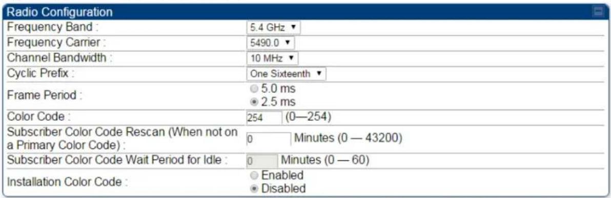
Zero Touch Configuration Using DHCP Option 66
This feature allows an SM to get its configuration via DHCP option 66. This can be used for the initial configuration of an SM as well as managing the configuration of SMs on an ongoing basis. Here is how it works in brief:
- When the SM boots up, if it is set to use DHCP client, it will send out a DHCP Discover packet which includes a request for DHCP Option 66.
- In case of a brand new SM out of the box, the DHCP Discover packet is sent out if the SM connects to an AP using Installation Color Code (ICC), even though DHCP client is not enabled in factory default config.
- An appropriately configured DHCP server will respond with a DHCP Offer and include a URL in response to the Option 66 request. The URL should point to the configuration file.
- The device will download the configuration file and apply it. The device will reboot automatically if needed. (Note: this requires "rebootIfRequired" flag to be added to the config file. See Creating a Golden config file on page 7-260.
Configuration Steps
Procedure 23 Zero Touch Configuration steps
1 Create the golden config file(s)
2 Host it on an TFTP/FTP/HTTP/HTTPS server
3 Configure the DHCP server to return the URL of the golden config file in option 66
When the SM boots up, it will get the URL for the golden config from the DHCP server via option 66, download it and apply it.
If all the SMs are configured exactly the same, then you can create just new golden config file that can be used with all SMs.
If the SMs are not configured the same, see if it is possible to group the SMs such that SMs with the same configuration are served by the same DHCP pool. User can then create multiple golden config files and configure the DHCP server to use the appropriate config file for each pool.
User can also create one config file per SM. This provides the most flexibility, but is practical only if you have a software tool/script to generate the config files for each MAC address. The files should be named
If some configuration is unique per SM, but rest of the configuration is common, the SMs can be staged with the unique part, and use option 66 to manage the common part. For example, if each SM needs to have its coordinates set, don't include the coordinates in the golden config file. Instead, configure the coordinates for each SM manually. Manage the rest of the configuration using DHCP option 66.
Creating a Golden config file
The easiest way to create the golden config file is to configure an SM, export its configuration and edit it. To export the configuration file from the GUI of the SM, go to "Configuration > Unit Settings" tab, go to the "Download Configuration File" section and click on the "
Strip down the config file to remove sections and entries that don't care about, and keep only the items that require changes. If there are many required changes, it can easily get confusing. To identify the exact items changes, first reset the SM to factory default, export the config file, make the necessary changes, export a second config file, then use a tool like WinMerge (http://winmerge.org/) to identify the differences.
The config file contains the following informational entries at the top level.
"cfgUtcTimestamp": "cfgUtcTimestamp",
"swVersion": "CANOPY 15.1 SM-AES",
"cfgFileString": "Canopy configuration file",
"srcMacAddress": "0a-00-3e-a2-c2-74",
"deviceType": "5.4/5.7GHz MIMO OFDM - Subscriber Module",
"cfgFileVersion": "1.0"
The "cfgUtcTimestamp", "swVersion", "srcMacAddress" and "deviceType" lines can be deleted. Do not delete the "cfgFileString" and "cfgFileVersion" entries.
Next, create an object named "configFileParameters" at the top level. Under that, add a parameter called "rebootIfRequired" and set it to true. This tells the SM to reboot automatically if a reboot is needed to apply the new configuration.
A sample configuration file that has been edited for use via DHCP option 66 is given below.
{
    "userParameters": {
    "smNetworkConfig": {
    "networkAccess": 1
    },
    "location": {
    "siteName": "Test site"
    },
    "smRadioConfig": {
"frequencyScanList": [
    5475000,
    5480000
],
    "colorCodeList": [
    {
    "colorCode": 42,
    "priority": 1
    }
]
},
"networkConfig": {
"lanDhcpState": 1
},
"cfgFileVersion": "1.0",
"cfgFileString": "Canopy configuration file",
"configFileParameters": {
"rebootIfRequired": true
}
}
When configuration is imported, only the items that exist in the configuration file are modified. Parameters that are not in the imported file are not changed. If user wish to revert those settings to their factory default values, please add a "setToDefaults" item under "configFileParameters" section with a value of true.
"cfgFileVersion": "1.0",
"cfgFileString": "Canopy configuration file",
"configFileParameters": {
    "rebootIfRequired": true,
    "setToDefaults": true
}
In case, the SM needs to fetch the configuration file on each boot up even when not connecting to AP via ICC, set "Network Accessibility" to "Public" and "DHCP State" to "Enabled" in the "Configuration > IP" page before exporting the configuration.
Hosting the config file
Copy the golden configuration file to an FTP, TFTP, HTTP or HTTPS server. This location can be password protected; you just have to include the user name and password in the URL.
DHCP server configuration
Configure DHCP server to return the full URL to the golden config file as the value of DHCP option 66.
The following example explains how to make the change for Windows Server 2008. Adapt it to your specific DHCP server.
Procedure 24 DHCP server configuration
1 Click "Start > Administrative Tools > DHCP"
2 If you have multiple "Scopes" defined, identify the correct "Scope" that will serve IP addresses for the SMs
3 Right click on "Scope Option" under the correct "Scope" and select "Configure Options"
![DHCP File Action View Help DHCP usil01pmpdhcp01 IPv4 Scope [10.120.163.0] Cambiur Address Pool Address Leases Reservations Scope Opti Server Options Filters IPv6 Configure Options... View Refresh Export List... Help Option Name 003 Router 006 DNS Servers 066 Boot Server Hos 015 DNS Domain Nar](/content/2026/05/943724/images/5019d4e41db47058aaf8850d7457b20131dfc63eccf1b63db3a18c12901bde0b.jpg)
4 In the "Scope Options" dialog, scroll down to "066 Boot Server Host Name", select the checkbox and enter the full URL to the golden config file as the "String value". Then click "OK".
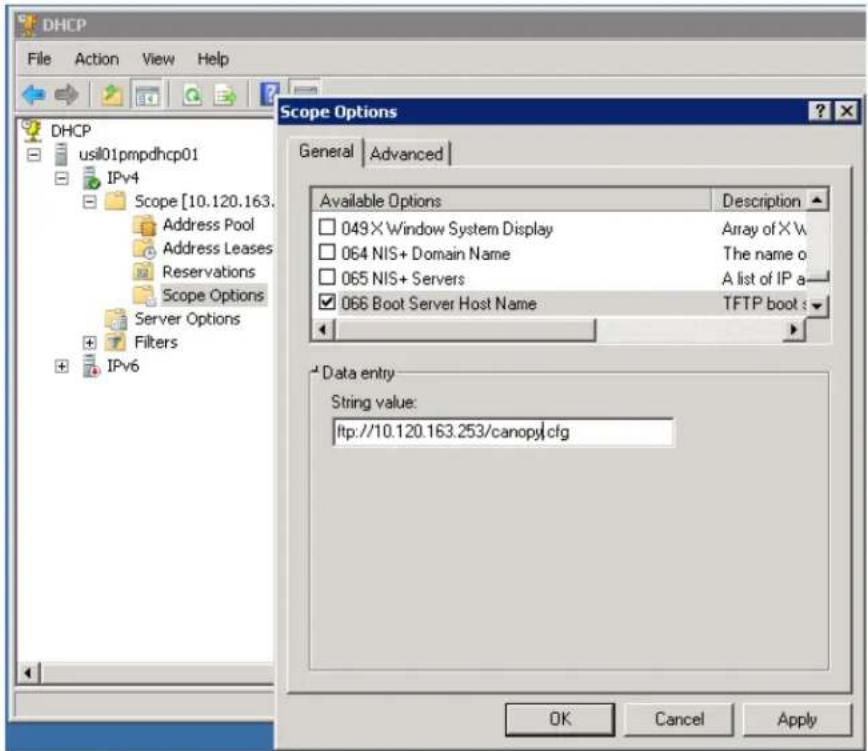
5 In the DHCP snap-in window, right click and "Refresh" to see the DHCP option 66 in the list of DHCP options
Supported URL Formats
FTP, TFTP, HTTP and HTTPS URLs are supported. Some examples are given below.
- ftp://10.120.163.253/canopy.cfg
- ftp://admin:admin123@10.120.163.253/canopy.cfg (login as admin with password admin123)
- tftp://10.120.163.253/canopy.cfg
- http://10.120.163.253/golden-config.cfg
- https://10.120.163.253/smconfig/golden-config.cfg
User can also specify the URL pointing to a directory and not a specific file. Terminate the URL with a '/' to indicate that it is a directory and not a file. Use this format when each SM has its own individual config file. The directory should contain files named "
For example:
ftp://10.120.163.253/smconfig/
In this case, the SM will append "
ftp://10.120.163.253/smconfig/0a003ea2c274.cfg. This mechanism can be used to serve individual config file for each SM.
Troubleshooting
1 Ensure that the__14 SM is running 13.3 or newer version of software.
2 If the SM has factory default config, confirm ICC is enabled on the AP, so the SM can connect to it.
3 If the SM is connecting to the AP using a color code other than ICC, make sure the SM has "Network Accessibility" set to "Public" and "DHCP State" set to "Enabled" in the "Configuration > IP" page.
4 Make sure the golden config file does not turn off "Network Accessibility" or "DHCP State". If it does, the SM will no longer request the config file when it is rebooted.
5 Check the event log of the SM to see the status of the configuration file import including any errors that prevented it from importing the file.
6 Capture the DHCP Offer packet from the DHCP server to the SM and verify that Option 66 has the expected URL.

Configuring Radio via config file
The 450 Platform Family supports export and import of a configuration file from the AP or SM as a text file. The configuration file is in JSON format.
To export or import the configuration file, the logged in user needs to be an ADMINISTRATOR and it must not be a "read-only" account.
The exported configuration file contains the complete configuration including all the default values. To keep a backup of the current configuration, the file can be saved as-is and imported later.
While importing a configuration file, it can be either imported the full configuration or a sparse configuration containing only the items that need to be changed. If a sparse configuration file is imported, only the items in the file will be imported. Other configuration will remain unchanged. There could also be used a special flag in the configuration file to tell the device to apply the configuration starting from factory default (Refer Special Headers for configuration file on page 7-266).
Import and Export of config file
The config file import and export is supported in Configuration > Unit Settings page. The procedure for importing and exporting config file is explained below.
Figure 167 Configuration File upload and download page

The DHCP server configuration procedure is as follows:
Procedure 25 DHCP server configuration
1 Login to the GUI and go to Configuration > Unit Settings.
2 Under Download Configuration File tab, click on the "
3 Save the file to the local disk.
The below procedure is to be followed for Importing a config file
Procedure 26 Import the configuration from the GUI
1 Login to the GUI and go to Configuration → Unit Settings.
2 Click on "Browse" button under "Upload and Apply Configuration File" tab and select the configuration file from disk.
3 Click "Upload" followed by "Apply Configuration File" button click.
4 The "Status of Configuration File" section will show the results of the upload.
5 Review it to make sure there are no errors. Then click on "Reboot" to reboot with the imported configuration
The special headers for config file is explained below:
Procedure 27 Special Headers for configuration file
1 A "configFileParameters" section can be added to the header to control the behavior of the device when importing configuration.
2 The "setToDefaults" when set to "true" tell the device to reset to factory default configuration and apply the configuration in the file on top of that. So any attribute not in the configuration file will be set to its factory default value. By default, the configuration in the file is merged with the existing configuration on the device.
The “rebootIfRequired” flag when set to “true” tell the device to reboot automatically if needed to apply the configuration change. By default, the device will not reboot automatically.
{
    "cfgFileString": "Canopy configuration file",
    "cfgFileVersion": "1.0",
    "configFileParameters": {
    "setToDefaults": true,
    "rebootIfRequired": true,
    }
}
Configuring cnMaestro™ Connectivity
450 Platform Family network can be onboarded, configured and managed using cnMaestro™
Cloud or On Premises Server.
Onboarding
Onboarding can be done in one of several ways:
• Using Cambium ID and Onboarding key
• Using Manufacturer's Serial Number (Only if it starts with an "M" and is 12 characters long)
• On Premises Zero Touch onboarding of AP/SM using DHCP option 43 and 15
- PMP SM Zero touch onboarding to the cnMaestro server where PMP AP is onboarded.
To configure the PMP devices, enable Remote Management under Configuration->cnMaestro as shown in Table 196.
Table 196 Configuring cnMaestro
| Configuration | |
| Remote Management : | EnableDisable |
| cnMaestro URL : | |
| Connection Status : | Cambium-ID Not Configured |
| Credentials | |
| Cambium ID : | |
| Onboarding Key : | |
| AccountID : | |
| Device Agent Information | |
| Device Agent Version : | 2.54 |
| Attribute | Meaning |
| Remote Management | This field enables/disables remote management of 450 Platform Family products. |
| cnMaestro URL | This field allows to enter cnMaestro URL e.g.https://cloud.cambiumnetworks.comOr cnMaestro on premises URL |
| Connection Status | This field indicates cnMaestro connectivity status. |
| Cambium ID | This field allows to enter Cambium ID for onboarding 450 Platform devices. |
| Onboarding Key | This field allows to enter Onboarding Key for onboarding. |
| AccountID | This field indicates Account ID of the customer. |
Device Agent
This field shows device agent version.
Version
Prerequisites for onboarding to cnMaestro™
- Devices types must be PMP 450m Series, PMP/PTP 450 Series, PMP/PTP 450i/450b Series or PMP 430 Series SMs (interoperability mode only).
- Minimum required software version of 14.2.1. Device software images can be downloaded from http://support.cambiumnetworks.com or from the On Premises cnMaestro server by navigating to Operate >Software Update->Manage Images. Select
- Device type to display the available images and then click the download icon as shown in Figure 168.
Figure 168 Software Upgrade from cnMaestro™
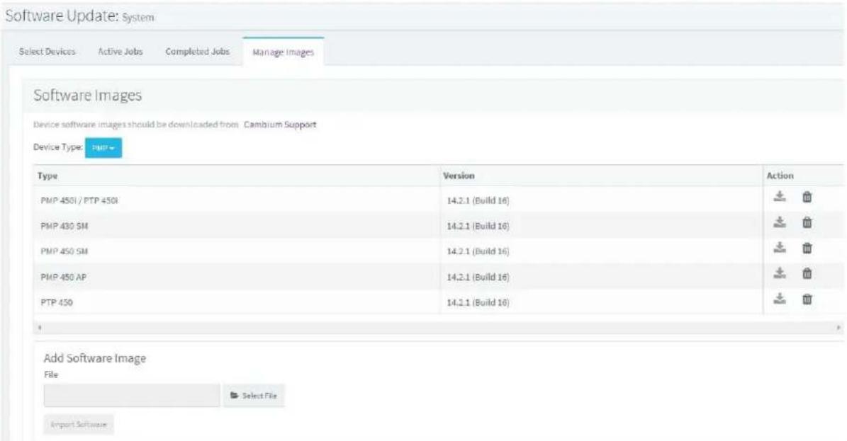
- IP connectivity between PMP Device and the cnMaestro server is established. Ensure Port 443 is open in the firewall as this port is used for secure communication between the PMP device and the cnMaestro server through web sockets. In addition, if the PMP device and cnMaestro™ server are on different subnets, proper routes should be established for communication.
- For PMP AP, a valid DNS setting is required so that the AP will be able to resolve the cnMaestro URL. DNS settings can be verified by performing a DNS lookup under Tools->DNS Test on the AP as shown in Figure 169.
Figure 169 DNS Test for cnMaestro™ connectivity

- If the SM is in Bridge mode, then LAN1 must have public 7-269equest7-269ility with a public IP assigned and corresponding DNS setting.
- If the SM is in NAT mode, then Remote Management should be enabled with the standalone configuration option and DNS settings.
Knowledge Based articles for onboarding
For onboarding the devices to cloud server and troubleshooting the onboarding issues in cloud server please see the following link:
http://community.cambiumnetworks.com/t5/cnMaestro/Device-On-boarding/td-p/51484
For onboarding the devices to on Premises server and configuring the DHCP server options for on boarding please see the following link:
http://community.cambiumnetworks.com/t5/cnMaestro/Device-Onboarding-and-Linux-DHCP-Options-for-cnMaestro-On/m-p/55187#U55187
Order of Device Onboarding
The device discovery order is as follows in On Permises cnMaestro™ Server. If any of the options is not configured, the discovery method will fallback to the next option:
- Static cnMaestro URL
- Zero Touch token (on boarding of PMP SMs when the corresponding AP is on boarded)
- DHCP Option 43
- DHCP Option 15
- https://cloud.cambiumnetworks.com
Device Agent Logs
For debugging any onboarding issues please check the device agent logs by navigating to Logs->Device Agent Logs on the PMP device GUI as shown in Figure 170. In addition, a tech support dump can for the PMP device can be obtained from cnMaestro™ by navigating to Monitor->Tools menu after selecting the particular PMP device in the tree and clicking the tech support file icon. This can be send to Cambium support for further troubleshooting.
Figure 170 Device Agent Logs
![Cambium Networks Home Configuration Statistics Tools Logs Accounts Quick Start Copyrightl Logoff Account: admin Level. ADMINISTRATOR Mode: Read-Write Authentication Method: Local CANOPY® AP Sessions AP Authentication State Machine Log AP Authorization State Machine Log EAP Radius Log Device Agent Log Logs → Device Agent Log 5.7GHz MIMO OFDM - Access Point 0a-00-3e-bb-01-9b Device Agent Log 10/05/2016 : 17:18:27 CDT : Attempting (re)connection in 5 seconds 10/05/2016 : 17:18:47 CDT : Timeout in select() - Cancelling! 10/05/2016 : 17:18:47 CDT : OpenConnection to 10.120.217.150.443 failed 10/05/2016 : 17:18:47 CDT : Rand_bytes failed, error code : 0 10/05/2016 : 17:18:47 CDT : Unable to discover cnMaestro URL (re-discover in 61 seconds) 10/05/2016 : 17:18:47 CDT : Attempting (re)connection in 61 seconds 10/05/2016 : 17:21:45 CDT : platform_set_fld_index: Failed to get index for field [cambiumCurrentulmageVersion] 10/05/2016 : 17:21:45 CDT : Invalid field [cambiumCurrentulmageVersion], please check Clear Refresh](/content/2026/05/943724/images/d92964043738af04c88cf940bfac6ddf740f167560dce0e2397d19886b6e2d8e.jpg)
Monitoring Tools for PMP Devices on cnMaestro™
cnMaestro™ as of this release offers several debugging tools for PMP devices. Some examples are:
• Pictorial view of network hierarchy
- Device status
- Tech support file
- Throughput
- Alarms
- Reboot
- Debug Logs
• Network connectivity - ping and DNS lookup
Figure 171 Example cnMaestro™ screenshot

flowchart
graph LR
    A["PMP 450i AP\n450iAP-216"] --> B["Up"]
    A --> C["0"]
    D["PMP 450 SM\n450iSM-217"] --> E["Up"]
    D --> F["0"]
    G["100Base-TX\nFull Duplex"] --> A
    G --> D
    H["0.01 Km"] --> D
    I["Throughput"] --> J["DL: 4.05 Kbps\nUL: 0.08 Kbps"]
For more information on these tools please see
http://community.cambiumnetworks.com/t5/cnMaestro/How-to-use-the-cnMaestro-Tools-
for-Troubleshooting-Device-or/m-p/54503#U54503
Zero Touch on boarding of the PMP SMs when the corresponding AP is on boarded
First a link should be established between the PMP AP and SM either by configuring manually or using the ICC. Once the AP and SM link is established, the AP must be onboarded to cnMaestro™ using one of several ways detailed above under the Onboarding section. Once the AP is onboarded to cnMaestro™ Cloud or On premises cnMaestro™ server, the SMs under the AP will automatically onboard to cnMaestro™ using a Zero touch token that is communicated between the AP and SMs. This is applicable to existing SMs registered to the AP as well as new SMs registering to the AP for the first time. The SMs appear on the onboarding queue of cnMaestro™ and the operator must “Approve” the devices in order to manage them.
The following operations for PMP Devices are available on cnMaestro™:
- Monitor the device details in the Dashboard page by navigating to the Monitor >Dashboard menu and selecting the PMP AP/SM in the tree.
- Monitor notifications related to the PMP AP/SM by navigating to the Monitor >Notifications Menu and selecting the PMP AP/SM in the tree.
- Monitor device statistics on the statistics page by navigating to the Monitor >Statistics menu and selecting the PMP AP/SM in the tree, then selecting the PMP AP or PMP SM in the Device type dropdown.
- Monitor Performance graphs related to the PMP AP/SM by navigating to the Monitor >Performance menu and selecting the required performance graph (i.e Throughput, SMs, Modulation) and selecting the PMP AP/SM in the tree.
-
Troubleshoot the device on the Troubleshooting page by navigating to the Monitor >Tools menu and selecting the PMP AP/SM in the tree.
-
Configure the devices by navigating to the Configure >Devices menu and selecting the PMP AP/SM in the tree and selecting the config template that needs to be pushed to the device. Configuration templates need to be created before the configuration can be pushed to the device. The template can be created by copying the existing configuration from the view device configuration link provided in the same page and then modifying the template as needed and then pushing to the same device or other similar devices. Template needs to be properly reviewed for IP Address and other critical parameters to avoid stranding SMs (resulting in a truck roll) by pushing an incorrect configuration. Configuration templates can be created by navigating to the Configure->Templates page and selecting the PMP device type while creating the template.
- Once on 14.2.1, PMP devices can be upgraded to future supported versions from cnMaestro™ by navigating to the Operate > Software Update page and selecting the "PMP Sectors" option from the device type drop-down and the version to which the device needs to be upgraded. It is recommended to upgrade the AP first, then the SMs.
- PMP Device Inventory details can be reviewed by navigating to the Monitor >Inventory page.
Configuring a RADIUS server
Configuring a RADIUS server in a PMP 450 Platform network is optional, but can provide added security, increase ease of network management and provide usage-based billing data.
Understanding RADIUS for PMP 450 Platform Family
PMP 450 Platform modules include support for the RADIUS (Remote Authentication Dial In User Service) protocol supporting Authentication and Accounting.
RADIUS Functions
RADIUS protocol support provides the following functions:
- SM Authentication allows only known SMs onto the network (blocking “rogue” SMs), and can be configured to ensure SMs are connecting to a known network (preventing SMs from connecting to “rogue” APs). RADIUS authentication is used for SMs, but is not used for APs.
- SM Configuration: Configures authenticated SMs with MIR (Maximum Information Rate), CIR (Committed Information Rate), Medium Priority, High Priority, and Ultra High Priority Data channels, and VLAN (Virtual LAN) parameters from the RADIUS server when a SM registers to an AP.
- User Authentication allows users to configure a separate User authentication server along with the SM authentication server. If firmware is upgraded while using this functionality and no User authentication servers are configured, then AP continues to use the SM authentication server for User authentication
- SM Accounting provides support for RADIUS accounting messages for usage-based billing. This accounting includes indications for subscriber session establishment, subscriber session disconnection, and bandwidth usage per session for each SM that connects to the AP.
- Centralized AP and SM user name and password management allows AP and SM usernames and access levels (Administrator, Installer, Technician) to be centrally administered in the RADIUS server instead of on each radio and tracks access events (logon/logoff) for each username on the RADIUS server. This accounting does not track and report specific configuration actions performed on radios or pull statistics such as bit counts from the radios. Such functions require an Element Management System (EMS) such as Cambium Networks Wireless Manager. This accounting is not the ability to perform accounting functions on the subscriber/end user/customer account.
- Framed IP allows operators to use a RADIUS server to assign management IP addressing to SM modules (framed IP address).
Tested RADIUS Servers
The Canopy RADIUS implementation has been tested and is supported on
• FreeRADIUS, Version 2.1.8
• Aradial RADIUS, Version 5.1.12
• Microsoft RADIUS (Windows Server 2012 R2 version)
• Cisco ACS, Version 5.7.0.15

Note
Aradial 5.3 has a bug that prevents “remote device login”, so doesn’t support the user name and password management feature.
Choosing Authentication Mode and Configuring for Authentication Servers - AP
On the AP's Configuration > Security tab, select the RADIUS AAA Authentication Mode. The following describes the other Authentication Mode options for reference, and then the RADIUS AAA option.
- Disabled: Requires no authentication. Any SM (except a SM that itself has been configured to require RADIUS authentication by enabling Enforce Authentication as described below) is allowed to register to the AP.
- Authentication Server: Authentication Server in this instance refers to Wireless Manager in BAM-only mode. Authentication is required for a SM to register to the AP. Only SMs listed by MAC address in the Wireless Manager database is allowed to register to the AP.
- AP Pre-Shared Key: Canopy offers a pre-shared key authentication option. In this case, an identical key must be entered in the Authentication Key field on the AP's Configuration > Security tab and in the Authentication Key field on each desired SM's Configuration > Security tab.
- RADIUS AAA: To support RADIUS authentication of SMs, on the AP's Configuration > Security tab select RADIUS AAA. Only properly configured SMs with a valid certificate is allowed to register to the AP.
When RADIUS AAA is selected, up to 3 Authentication Server (RADIUS Server) IP addresses and Shared Secrets can be configured. The IP address(s) configured here must match the IP address(s) of the RADIUS server(s). The shared secret(s) configured here must match the shared secret(s) configured in the RADIUS server(s). Servers 2 and 3 are meant for backup and reliability, not splitting the database. If Server 1 doesn't respond, Server 2 is tried, and then server 3. If Server 1 rejects authentication, the SM is denied entry to the network, and does not progress trying the other servers.
The default IP address is 0.0.0.0. The default Shared Secret is "CanopySharedSecret". The Shared Secret can be up to 32 ASCII characters (no diacritical marks or ligatures, for example).
Table 197 Security tab attributes
| Authentication Server Settings | ||
| Authentication Mode: | Disabled | |
| Authentication Server DNS Usage: | Append DNS Domain NameDisable DNS Domain Name | |
| Authentication Server 1: | Shared Secret | |
| 0.0.0.0 | ||
| Authentication Server 2: | Shared Secret | |
| 0.0.0.0 | ||
| Authentication Server 3: | Shared Secret | |
| 0.0.0.0 | ||
| Authentication Server 4 (BAM ONLY): | 0.0.0.0 | |
| Authentication Server 5 (BAM ONLY): | 0.0.0.0 | |
| Radius Port: | 1812 | Default port number is 1812 |
| Authentication Key: | (Using All 0xFF's Key) | |
| Select Key: | Use Key aboveUse Default Key | |
| Dynamic Authorization Extensions for RADIUS: | Enable CoA and Disconnect MessageDisable CoA and Disconnect Message | |
| Bypass Authentication for ICC SMs: | EnabledDisabled | |
| Airlink Security | |
| Encryption Setting: | None ▼ |
| AP Evaluation Configuration | |
| SM Display of AP Evaluation Data : | Disable DisplayEnable Display |
| Session Timeout | ||
| Web, Telnet, FTP Session Timeout : | 600 | Seconds |
| IP Access Filtering | |||
| IP Access Control : | IP Access Filtering Enabled - Only allow access from IP addresses specified belowIP Access Filtering Disabled - Allow access from all IP addresses | ||
| Allowed Source IP 1 : | 0.0.0.0 | / | 32 Network Mask (set to 32 to disable) |
| Allowed Source IP 2 : | 0.0.0.0 | / | 32 Network Mask (set to 32 to disable) |
| Allowed Source IP 3 : | 0.0.0.0 | / | 32 Network Mask (set to 32 to disable) |
| Security Mode | |
| Web Access : | HTTP Only |
| SNMP : | SNMPv2c Only |
| Telnet : | EnabledDisabled |
| FTP : | EnabledDisabled |
| TFTP : | EnabledDisabled |
| NTP server : | EnabledDisabled |
| Attribute | Meaning |
| Authentication Mode | Operators may use this field to select the following authentication modes:Disabled-the AP requires no SMs to authenticate.Authentication Server -the AP requires any SM that attempts registration to be authenticated in Wireless Manager before registration.AP PreShared Key - The AP acts as the authentication server to its SMs and will make use of a user-configurable pre-shared authentication key. The operator enters this key on both the AP and all SMs desired to register to that AP. There is also an option of leaving the AP and SMs at their default setting of using the “Default Key”. Due to the nature of the authentication operation, if you want to set a specific authentication key, then you MUST configure the key on all of the SMs and reboot them BEFORE enabling the key and option on the AP. Otherwise, if you configure the AP first, none of the SMs is able to register.RADIUS AAA - When RADIUS AAA is selected, up to 3Authentication Server (RADIUS Server) IP addresses and Shared Secrets can be configured. The IP address(s) configured here must match the IP address(s) of the RADIUS server(s). The shared secret(s) configured here must match the shared secret(s) configured in the RADIUS server(s). Servers 2 and 3 are meant for backup and reliability, not for splitting the database. If Server 1 doesn't respond, Server 2 is tried, and then server 3. If Server 1 rejects authentication, the SM is denied entry to the network and does not progress trying the other servers. |
| Authentication Server DNS Usage | The management DNS domain name may be toggled such that the name of the authentication server only needs to be specified and the DNS domain name is automatically appended to that name. |
| Authentication Server 1 | |
| Authentication Server 2 | Enter the IP address or server name of the authentication server (RADIUS or WM) and the Shared Secret configured in the authentication server. When Authentication Mode RADIUS AAA is selected, the default value of Shared Secret is “CanopySharedSecret”. The Shared Secret may consist of up to 32 ASCII characters. |
| Authentication Server 3 | |
| Authentication Server 4 (BAM Only) | |
| Authentication Server 5 (BAM Only) |
| Radius Port This field allows the operator to configure a custom port for RADIUS server communication. The default value is 1812. | ||
| Authentication Key | The authentication key is a 32-character hexadecimal string used when Authentication Mode is set to AP Pre-Shared Key. By default, this key is set to 0xFFFFFFFFFFFFFFFFFFFFFFFF | |
| Selection Key | This option allows operators to choose which authentication key is used:Use Key above means that the key specified in Authentication Key is used for authenticationUse Default Key means that a default key (based off of the SM's MAC address) is used for authentication | |
| Encryption Key | Specify the type of airlink security to apply to this AP. The encryption setting must match the encryption setting of the SMs.None provides no encryption on the air link.AES (Advanced Encryption Standard): An over-the-air link encryption option that uses the Rijndael algorithm and 128-bit keys to establish a higher level of security. AES products are certified as compliant with the Federal Information Processing Standards (FIPS 197) in the U.S.A. | |
| SM Display of AP Evaluation Data | You can use this field to suppress the display of data about this AP on the AP Evaluation tab of the Tools page in all SMs that register. | |
| Web, Telnet, FTP Session Timeout | Enter the expiry in seconds for remote management sessions via HTTP, telnet, or ftp access to the AP. | |
| IP Access Control | You can permit access to the AP from any IP address (IP Access Filtering Disabled) or limit it to access from only one, two, or three IP addresses that you specify (IP Access Filtering Enabled). If you select IP Access Filtering Enabled, then you must populate at least one of the three Allowed Source IP parameters or have no access permitted from any IP address | |
| Allowed Source IP 1 | If you selected IP Access Filtering Enabled for the IP Access Control parameter, then you must populate at least one of the three Allowed Source IP parameters or have no access permitted to the AP from any IP address. You may populate as many as all three. | |
| Allowed Source IP 2 | If you selected IP Access Filtering Disabled for the IP Access Control parameter, then no entries in this parameter are read, and access from all IP addresses is permitted. | |
| Allowed Source IP 3 | ||
| Web Access | The Radio supports secured and non-secured web access protocols. Select suitable web access from drop-down list:HTTP Only - provides non-secured web access. The radio to be accessed viahttp://.HTTPS Only - provides a secured web access. The radio to be accessed viahttps://. | |
| HTTP and HTTPS - If enabled, the radio can be accessed via both http and https. | ||
| SNMP | This option allows to configure SNMP agent communication version.It can be selected from drop-down list:SNMPv2c Only - Enables SNMP v2 community protocol.SNMPv3 Only - Enables SNMP v3 protocol. It is secured communication protocol.SNMPv2c and SNMPv3 - It enables both the protocols. | |
| Telnet This option allows to | Enable and Disable Telnet access to the Radio. | |
| FTP This option allows to | Enable and Disable FTP access to the Radio. | |
| TFTP This option allows to | Enable and Disable TFTP access to the Radio. | |
| NTP server | This option allows to Enable and Disable NTP server access to the Radio. | |
SM Authentication Mode - Require RADIUS or Follow AP
If it is desired that a SM will only authenticate to an AP that is using RADIUS, on the SM's Configuration Security tab set Enforce Authentication to AAA. With this enabled, SM does not register to an AP that has any Authentication Mode other than RADIUS AAA selected.
If it is desired that a SM use the authentication method configured on the AP it is registering to, set Enforce Authentication to Disabled. With Enforce Authentication disabled, a SM will attempt to register using whichever Authentication Mode is configured on the AP it is attempting to register to.

Note
Having SMs to use RADIUS by enabling Enforce Authentication avoids the security issue of SMs possibly registering to “rogue” APs, which have authentication disabled.
Table 198 SM Security tab attributes
| Authentication Key Settings | ||
| Authentication Key : | (Using All 0xFF's Key) | |
| Select Key : | Use Key aboveUse Default Key | |
| AAA Authentication Settings | ||
| Enforce Authentication : | Disable | |
| Phase 1 : | eaptils | |
| Phase 2 : | MSCHAPv2 | |
| Identity/Realm : | Enable RealmDisable RealmIdentity anonymous @ Realm canopy.net | |
| Username : | 0a-00-3e-a0-00-6c | Use Default Username |
| Password : | ...... | |
| Confirm Password : | ||
| RADIUS Certificate Settings | |
| Upload Certificate File | |
| File: Choose File No file chosen | |
| Import Certificate | |
| Use Default Certificates | |
| This will delete all current certificates | |
| Certificate 1 | |
| C =US | |
| S =Illinois | |
| O = | Solutions, Inc. |
| OU =Canopy Wireless Broadband | |
| CN =Canopy AAA Server Demo CA | |
| E =technical-support@canopywireless.com | |
| Valid From: 01/01/2001 00:00:00 | |
| Valid To: 12/31/2049 23:59:59 | |
| Delete | |
| Certificate 2 |
| Certificate 2 deleted. |
| Airlink Security | |
| Encryption Setting : | DES ▼ |
| Session Timeout | ||
| Web, Telnet, FTP Session Timeout: | 600000 | Seconds |
| SM Management Interface Access via Ethernet Port | |
| Ethernet Access: | EnabledDisabled |
| IP Access Filtering | |||
| IP Access Control: | IP Access Filtering Enabled - Only allow access from IP addresses specified belowIP Access Filtering Disabled - Allow access from all IP addresses | ||
| Allowed Source IP 1: | 0.0.0.0 | /32 | Network Mask (set to 32 to disable) |
| Allowed Source IP 2: | 0.0.0.0 | /32 | Network Mask (set to 32 to disable) |
| Allowed Source IP 3: | 0.0.0.0 | /32 | Network Mask (set to 32 to disable) |
| Security Mode | |
| Web Access: | HTTP Only▼ |
| SNMP: | SNMPv2o Only▼ |
| Telnet: | EnabledDisabled |
| FTP: | EnabledDisabled |
| TFTP: | EnabledDisabled |
Attribute
Meaning
| Authentication Key | The authentication key is a 32-character hexadecimal string used when Authentication Mode is set to AP PreShared Key. By default, this key is set to 0xFFFFFFFFFFFFFFFFFFFFFFFF | |
| Select Key | This option allows operators to choose which authentication key is used:Use Key above means that the key specified in Authentication Key is used for authenticationUse Default Key means that a default key (based off of the SM's MAC address) is used for authentication | |
| Enforce Authentication | The SM may enforce authentication types of AAA and AP Pre-sharedKey. The SM will not finish the registration process if the AP is not using the configured authentication method (and the SM locks out the AP for 15 minutes). Enforce Authentication default setting is Disable. | |
| Phase 1 | The protocols supported for the Phase 1 (Outside Identity) phase of authentication are EAPTTLS (Extensible Authentication Protocol Tunneled Transport Layer Security) or MSCHAPv2 (Microsoft Challenge-Handshake Authentication Protocol version 2). | |
| Phase 2 | Select the desired Phase 2 (Inside Identity) authentication protocol from the Phase 2 options of PAP (Password Authentication Protocol), CHAP (Challenge Handshake Authentication Protocol), and MSCHAP ( Microsoft's version of CHAP, version 2 is used). The protocol must be consistent with the authentication protocol configured on the RADIUS server. | |
| Identity/Realm | If Realms are being used, select Enable Realm and configure an outer identity in the Identity field and a Realm in the Realm field. These must match the Phase 1/Outer Identity and Realm configured in the RADIUS server. The default Identity is “anonymous”. The Identity can be up to 128 non-special (no diacritical markings) alphanumeric characters. The default Realm is “canopy.net”. The Realm can also be up to 128 non-special alphanumeric characters. Configure an outer Identity in the Username field. This must match the Phase 1/Outer Identity username configured in the RADIUS server. The default Phase 1/Outer Identity Username is “anonymous”. The Username can be up to 128 non-special (no diacritical markings) alphanumeric characters. | |
| Username | Enter a Username for the SM. This must match the username configured for the SM on the RADIUS server. The default Username is the SM’s MAC address. The Username can be up to 128 non-special (no diacritical markings) alphanumeric characters. | |
| Password | Enter the desired password for the SM in the Password and Confirm Password fields. The Password must match the password configured for the SM on the RADIUS server. The default Password is “password”. The Password can be up to 128 non-special (no diacritical markings) alphanumeric characters. | |
| Confirm Password | ||
| Upload Certificate File | To upload a certificate manually to a SM, first load it in a known place on your PC or network drive, then click on a Delete button on one of the Certificate description blocks to delete a certificate to provide space for your certificate. Click on Choose File, browse to the location of the certificate, and click the Import Certificate button, and then reboot the radio to use the new certificate.When a certificate is in use, after the SM successfully registers to an AP, an indication of In Use will appear in the description block of the certificate being used.The public certificates installed on the SMs are used with the private certificate on the RADIUS server to provide a public/private key encryption system.Up to 2 certificates can be resident on a SM. An installed certificate can be deleted by clicking the Delete button in the certificate’s description block on the Configuration > Security tab. To restore the 2 default certificates, click the Use Default Certificates button in the RADIUS Certificate Settings parameter block and reboot the radio. | |
| Encryption Setting | Specify the type of airlink security to apply to this AP. The encryption setting must match the encryption setting of the SMs.None provides no encryption on the air link.AES (Advanced Encryption Standard): An over-the-air link encryption option that uses the Rijndael algorithm and 128-bit keys to establish a higher level of security. AES products are certified as compliant with the Federal Information Processing Standards (FIPS 197) in the U.S.A. | |
| Web, Telnet, FTP Session Timeout | Enter the expiry in seconds for remote management sessions via HTTP, telnet or ftp access to the AP. | |
| Ethernet Access | If you want to prevent any device that is connected to the Ethernet port of the SM from accessing the management interface of the SM, select Ethernet Access Disabled. This selection disables access through this port to via HTTP (the GUI), SNMP, telnet, FTP, and TFTP. With this selection, management access is available through only the RF interface via either an IP address (if Network Accessibility is set to Public on the SM) or the Session Status or Remote Subscribers tab of the AP. See IP Access Control below.If you want to allow management access through the Ethernet port, select Ethernet Access Enabled. This is the factory default setting for this parameter. | |
| IP Access Control | You can permit access to the AP from any IP address (IP Access Filtering Disabled) or limit it to access from only one, two, or three IP addresses that you specify (IP Access Filtering Enabled). If you select IP Access Filtering Enabled, then you must populate at least one of the three Allowed Source IP parameters or have no access permitted from any IP address | |
| Allowed Source IP 1 | If you selected IP Access Filtering Enabled for the IP Access Control parameter, then you must populate at least one of the three Allowed Source IP parameters or have no access permitted to the AP from any IP address. You may populate as many as all three. | |
| Allowed Source IP 2 | ||
| Allowed Source IP 3 | If you selected IP Access Filtering Disabled for the IP Access Control parameter, then no entries in this parameter are read, and access from all IP addresses is permitted. | |
| Web Access | The Radio supports secured and non-secured web access protocols. Select suitable web access from drop-down list:HTTP Only - provides non-secured web access. The radio to be accessed viahttp://.HTTPS Only - provides a secured web access. The radio to be accessed viahttps://.HTTP and HTTPS - If enabled, the radio can be accessed via both http and https. | |
| SNMP | This option allows to configure SNMP agent communication version. It can be selected from drop-down list:• SNMPv2c Only - Enables SNMP v2 community protocol.• SNMPv3 Only - Enables SNMP v3 protocol. It is secured communication protocol.• SNMPv2c and SNMPv3 - It enables both the protocols. | |
| Telnet This option allows to | Enable and Disable Telnet access to the Radio. | |
| FTP This option allows to | Enable and Disable FTP access to the Radio. | |
| TFTP This option allows to | Enable and Disable TFTP access to the Radio. | |
SM - Phase 1 (Outside Identity) parameters and settings
The protocols supported for the Phase 1 (Outside Identity) phase of authentication are eapttls (Extensible Authentication Protocol Tunneled Transport Layer Security) and eapMSChapV2 (Extensible Authentication Protocol - Microsoft Challenge-Handshake Authentication Protocol).
Configure an outer Identity in the Username field. This must match the Phase 1/Outer Identity username configured in the RADIUS server. The default Phase 1/Outer Identity Username is “anonymous”. The Username can be up to 128 non-special (no diacritical markings) alphanumeric characters. If Realms are being used in the RADIUS system (eapttls only), select Enable Realm and configure an outer identity in the Identity field and a Realm in the Realm field. These must match the Phase 1/Outer Identity and Realm configured in the RADIUS server. The default Identity is “anonymous”. The Identity can be up to 128 non-special (no diacritical markings) alphanumeric characters. The default Realm is “canopy.net”. The Realm can also be up to 128 non-special alphanumeric characters.
SM - Phase 2 (Inside Identity) parameters and settings
If using eapttls for Phase 1 authentication, select the desired Phase 2 (Inside Identity) authentication protocol from the Phase 2 options of PAP (Password Authentication Protocol), CHAP (Challenge Handshake Authentication Protocol), and MSCHAPv2 (Microsoft's version of CHAP). The protocol must be consistent with the authentication protocol configured on the RADIUS server. Enter a Username for the SM. This must match the username configured for the SM on the RADIUS server. The default Username is the SM's MAC address. The Username can be up to 128 non-special (no diacritical markings) alphanumeric characters.
Enter the desired password for the SM in the Password and Confirm Password fields. The Password must match the password configured for the SM on the RADIUS server. The default Password is "password". The Password can be up to 128 non-special (no diacritical markings) alphanumeric characters.
Handling Certificates
Managing SM Certificates via the SM GUI
The default public Canopy certificates are loaded into SMs upon factory software installation. The default certificates are not secure and are intended for use during lab and field trials as part of gaining experience with the RADIUS functionalities or as an option during debug. For secure operation, an operator will want to create or procure their own certificates. Resetting a SM to its factory defaults will remove the current certificates and restore the default certificates.
Up to two certificates can be resident on a SM. An installed certificate can be deleted by clicking the Delete button in the certificate's description block on the Configuration > Security tab. To restore the 2 default certificates, click the Use Default Certificates button in the RADIUS Certificate Settings parameter block and reboot the radio.
To upload a certificate manually to a SM, first load it in a known place on your PC or network drive, then click on a Delete button on one of the Certificate description blocks to delete a certificate to provide space for your certificate. Click on Choose File, browse to the location of the certificate, and click the Import Certificate button, and then reboot the radio to use the new certificate.
When a certificate is in use, after the SM successfully registers to an AP, an indication of In Use will appear in the description block of the certificate being used.
The public certificates installed on the SMs are used with the private certificate on the RADIUS server to provide a public/private key encryption system.

Note
Root certificates of more than one level (Example - a certificate from someone who received their CA from Verisign) fails. Certificates must be either root or self-signed.
Figure 172 SM Certificate Management


Configuring RADIUS servers for SM authentication
Your RADIUS server must be configured to use the following:
• EAPTTLS or MSCHAPv2 as the Phase 1/Outer Identity protocol.
- If Enable Realm is selected on the SM's Configuration > Security tab, then the same Realm appears there (or access to it).
- The same Phase 2 (Inner Identity) protocol as configured on the SM's Configuration > Security tab under Phase 2 options.
- The username and password for each SM configured on each SM's Configuration > Security tab.
- An IP address and NAS shared secret that is the same as the IP address and Shared Secret configured on the AP's Configuration > Security tab for that RADIUS server.
- A server private certificate, server key, and CA certificate that complement the public certificates distributed to the SMs, as well as the Canopy dictionary file that defines Vendor Specific Attributes (VSAa). Default certificate files and the dictionary file are available from the software site: https://support.cambiumnetworks.com/files/pmp450 after entering your name, email address, and either Customer Contract Number or the MAC address of a module covered under the 12 month warranty.
Optionally, operators may configure the RADIUS server response messages (Accept or Reject) so that the user has information as to why they have been rejected. The AP displays the RADIUS Authentication Reply message strings in the Session Status list as part of each SM's information. The SM will show this string (listed as Authentication Response on the SM GUI) on the main Status page in the Subscriber Module Stats section.

Note
Aradial AAA servers only support operator-configurable Authentication Accept responses, not Authentication Reject responses.
Assigning SM management IP addressing via RADIUS
Operators may use a RADIUS AAA server to assign management IP addressing to SM modules (framed IP address). SMs now interpret attributes Framed-IP-Address, Framed-IP-Netmask, and Cambium-Canopy-Gateway from RADIUS. The RADIUS dictionary file has been updated to include the Cambium-Canopy-Gateway attribute and is available on the Cambium Software Support website.
In order for these attributes to be assigned and used by the SM, the following must be true:
• The system is configured for AAA authentication
- The SM is not configured for DHCP on its management interface. If DHCP is enabled and these attributes are configured in the RADIUS server, the attributes is ignored by the SM.
- The SM management interface must be configured to be publicly accessible. If the SM is configured to have local accessibility, the management interface will still be assigned the framed addressing, and the SM iscome publicly accessible via the assigned framed IP addressing.
- When using these attributes, for the addressing to be implemented by the SM operators must configure Framed-IP-Address in RADIUS. If Framed-IP-Address is not configured but Framed-IP-Netmask and/or Cambium-Canopy-Gateway is configured, the attributes is ignored. In the case where only the Framed-IP-Address is configured, Framed-IP-Netmask defaults to 255.255.0.0 (NAT disabled) / 255.255.255.0 (NAT enabled) and Cambium-Canopy-Gateway defaults to 0.0.0.0.
Configuring RADIUS server for SM configuration
Canopy Vendor Specific Attributes (VSAs) along with VSA numbers and other details are listed in Table 199. The associated SM GUI page, tab and parameter are listed to aid cross-referencing and understanding of the VSAs.
A RADIUS dictionary file is available from the software site:
https://support.cambiumnetworks.com/files/pmp450
The RADIUS dictionary file defines the VSAs and their values and is usually imported into the RADIUS server as part of server and database setup.

Note
Beginning with System Release 12.0.2, two RADIUS dictionary files are available on the Cambium website – “RADIUS Dictionary file – Cambium” and “RADIUS Dictionary file – Motorola”.
In addition to a renaming of attributes, the Cambium-branded dictionary file contains two new VSAs for controlling uplink and downlink Maximum Burst Data Rate (these VSAs are listed below in Table 199).
If you are transitioning from the Motorola-branded dictionary file to the Cambium-branded dictionary file, ensure that all RADIUS profiles containing Motorola-Canopy attribute references are updated to include Cambium-Canopy attribute references (for all applicable VSAs listed in Table 199). Also, ensure that all RADIUS configuration files reference the new dictionary file (as an alternative, operators may rename the Cambium-branded dictionary file to the filename currently in use by the RADIUS server). Once the profiles are updated and the new Cambium-branded dictionary file is installed on the RADIUS server, restart the RADIUS server to ensure that the new VSAs and attribute names are enabled.
Table 199 RADIUS Vendor Specific Attributes (VSAs)
| Name | Number | Type | Required | Value |
| MS-MPPE-Send-Key* | 26.311.16 | - | Y | - |
| - - - | ||||
| MS-MPPE-Recv-Key* | 26.311.17 | - | Y | - |
| - | - | |||
| Cambium-Canopy-LPULCIR | 26.161.1 integer N | 0-65535 kbps | ||
| Configuration > Quality of Service > Low Priority Uplink CIR | 0 kbps 32 bits | |||
| Cambium-Canopy-LPDLCIR | 26.161.2 integer N | 0-65535 kbps | ||
| Configuration > Quality of Service > Low Priority Downlink CIR | 0 kbps 32 bits | |||
| Cambium-Canopy-HPULCIR | 26.161.3 integer N | 0-65535 kbps | ||
| Configuration > Quality of Service > High Priority Uplink CIR | 0 kbps 32 bits | |||
| Cambium-Canopy-HPDLCIR | 26.161.4 integer N | 0-65535 kbps | ||
| Configuration > Quality of Service > High Priority Uplink CIR | 0 kbps 32 bits | |||
| Cambium-Canopy-HPENABLE | 26.161.5 | integer | N | 0-disable, 1-enable | |
| Configuration > Quality of Service > High Priority Channel Enable/Disable | 0 | 32 bits | |||
| 26.161.6 | integer | N 0-100000 | kbps | ||
| Configuration > Quality of Service > Sustained Uplink Data Rate | dependent on radio feature set | 32 bits | |||
| Cambium-Canopy-ULBL | 26.161.7 | integer | N 0-2500000 | kbps | |
| Configuration > Quality of Service > Uplink Burst Allocation dependent on radio feature set | on radio | 32 bits | |||
| Cambium-Canopy-DLBR | 26.161.8 | integer N | 0-100000 | kbps | |
| Configuration > Quality of Service > Sustained Downlink Data Rate | dependent on radio feature set | 32 bits | |||
| Cambium-Canopy-DLBL | 26.161.9 | integer N | 0-2500000 kbps | ||
| Configuration > Quality of Service > Downlink Burst Allocation | dependent on radio feature set | 32 bits | |||
| Cambium-Canopy-VLLEARNEN | 26.161.14 | integer N | 0-disable, 1-enable | ||
| Configuration > VLAN > Dynamic Learning 1 | 32 | bits | |||
| Cambium-Canopy-VLFRAMES | 26.161.15 | integer N | 0-all, 1-tagged, 2-untagged | ||
| Configuration > VLAN > Allow Frame Types | 0 | 32 bits | |||
| Cambium-Canopy-VLIDSET | 26.161.16 | integer N | VLAN Membership (1-4094) | ||
| Configuration > VLAN Membership | 0 | 32 bits | |||
| Cambium-Canopy-VLAGETO | 26.161.20 | integer N | 5 - 1440 minutes | ||
| Configuration > VLAN > VLAN Aging Timeout | 25 mins | 32 bits | |||
| Cambium-Canopy-VLIGVID | 26.161.21 | integer N | 1 - 4094 | ||
| Configuration > VLAN > Default Port VID | 1 32 | bits | |||
| Cambium-Canopy-VLMGVID | 26.161.22 | integer N | 1 - 4094 | ||
| Configuration > VLAN > Management VID 1 | 32 | bits | |||
| Cambium-Canopy-VLSMMGPASS | 26.161.23 | integer | N | 0-disable, 1-enable | |
| Configuration > VLAN > SM Management VID Pass-through 1 | 32 | bits | |||
| Cambium-Canopy-BCASTMIR | 26.161.24 | integer | N | 0-100000 kbps,0=disabled | |
| Configuration > Quality of Service > Broadcast/Multicast Uplink Data Rate | dependent on radio feature set | 32 bits | |||
| Cambium-Canopy-Gateway | 26.161.25 | ipaddr | N | - | |
| Configuration > IP > Gateway IP Address | 0.0.0.0 - | ||||
| Cambium-Canopy-ULMB | 26.161.26 | integer | N | 0-100000 kbps | |
| Configuration > Quality of Service > Max Burst Uplink Data Rate | 0 32 | bits | |||
| Cambium-Canopy-DLMB | 26.161.27 | integer | N | 0-100000 kbps | |
| Configuration > Quality of Service > Max Burst Downlink Data Rate | 0 32 | bits | |||
| Cambium-Canopy-UserLevel | 26.161.50 | integer | N | 1-Technician, 2-Installer, 3-Administrator | |
| Account > Add User > Level | 0 | 32 bits | |||
| Cambium-Canopy-DHCP-State | 26.161.31 | integer | N | 1-Enable | |
| Configuration > IP > DHCP state | 1 | 32 bits | |||
| Cambium-Canopy-BCASTMIRUNITS | 26.161.28 | integer | N | ||
| Configuration > QoS > Broadcast Downlink CIR | 0 | 32 bits | |||
| Cambium-Canopy-ConfigFileImportUrl | 26.161.29 | string | N | ||
| Configuration > Unit Settings | 0 32 | bits | |||
| Cambium-Canopy-ConfigFileExportUrlConfiguration > Unit Settings | 26.161.300 32 | string | N | bits | |
| Cambium-Canopy-UserMode | 26.161.51 | integer | N | 1=Read-Only0=Read-Write | |
| Account > Add User > User Mode | 0 32 | bits | |||
(*) Contains key for encrypting packets sent by the NAS to the remote host (for Microsoft Point-to-Point Encryption Protocol).

Note
VSA numbering:
26 connotes Vendor Specific Attribute, per RFC 2865
26.311 is Microsoft Vendor Code, per IANA
Configuring RADIUS server for SM configuration using Zero Touch feature
The RADIUS VSA (Vendor Specific Attributes) is updated for Zero Touch feature. This feature enables the ability for a SM to get its configuration via RADIUS VSA. The RADIUS VSA is updated for an URL which points to the configuration file of SM (see Table 199 for list of VSA).
The RADIUS will push the vendor specific attribute to SM after successful authentication. The VSA contains URL of config file which will redirect SM to download configuration. If there is any change in SM confirmation, the SM will reboot automatically after applying the configuration.
The RADIUS VSA attributes concerning Zero Touch are as follows:
VSA
Type
String
Cambium-Canopy-ConfigFileImportUrl (29) string Maximum Length 127 characters.
Cambium-Canopy-ConfigFileExportUrl (30) string Maximum Length 127 characters.
The updated RADIUS dictionary can be downloaded from below link:
https://support.cambiumnetworks.com/files/pmp450/

Note
The feature is not applicable to the AP.
Using RADIUS for centralized AP and SM user name and password management
AP - Technician/Installer/Administrator Authenti cation
To control technician, installer, and administrator access to the AP from a centralized RADIUS server:
Procedure 28 Centralized user name and password management for AP
| 1 | Set Authentication Mode on the AP's Configuration > Security tab to RADIUS AAA |
| 2 | Set User Authentication Mode on the AP's Account > User Authentication tab (the tab only appears after the AP is set to RADIUS authentication) to Remote or Remote then Local.Local: The local SM is checked for accounts. No centralized RADIUS accounting (access control) is performed.Remote: Authentication by the centralized RADIUS server is required to gain access to the SM if the SM is registered to an AP that has RADIUS AAA Authentication Mode selected. For up to 2 minutes a test pattern is displayed until the server responds or times out.Remote then Local : Authentication using the centralized RADIUS server is attempted. If the server sends a reject message, then the setting of Allow Local Login after Reject from AAA determines if the local user database is checked or not. If the configured servers do not respond within 2 minutes, then the local user database is used. The successful login method is displayed in the navigation column of the SM. |
User administration and authentication separation
On the AP, it is possible to configure up to three User Authentication servers, along with their Shared Secret. If none of the User Authentication servers are configured, the AP continues to use SM Authorization servers for User Authentication.
If at least one of the IP addresses is configured, all Authentication, Authorization, and Accounting requests now follow the newly configured User Authorization server.
To configure separate User Authentication and SM Authentication:
Procedure 29 User administration and authentication separation
1 Go to the AP's Account > User Authentication And Access Tracking tab
2 Set User Authentication Mode to Remote or Remote then Local.
3 Set User Authentication Method to EAP-MD5 or EAP-PEAP-MSCHAPv2
4 Configure the Shared Secrets and IP Addresses of:
User Authentication Server 1
User Authentication Server 2
User Authentication Server 3
Note: If none of the above User Authentication servers are configured, only SM authentication will be performed.
5 Under RADIUS Certificate Settings, click Browse to upload the RADIUS Certificate files.
Table 200 AP User Authentication and Access Tracking attributes
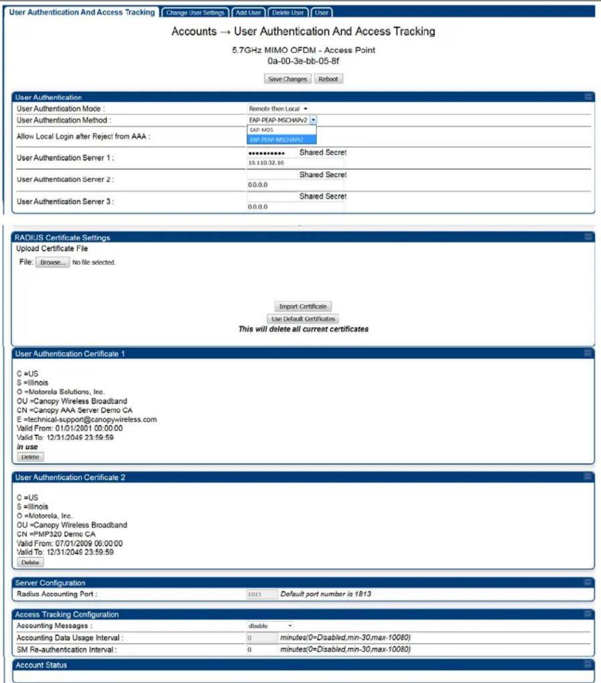
| Attribute | Meaning |
| User Authentication Mode | Local: The local SM is checked for accounts. No centralized RADIUS accounting (access control) is performed.Remote: Authentication by the centralized RADIUS server is required to gain access to the AP. For up to 2 minutes a test pattern is displayed until the server responds or times out.Remote then Local : Authentication using the centralized RADIUS server is attempted. If the server sends a reject message, then the setting of Allow Local Login after Reject from AAA determines if the local user database is checked or not. If the configured servers do not respond within 2 minutes, then the local user database is used. The successful login method is displayed in the navigation column of the AP. |
| User Authentication Method | The user authentication method employed by the radios:EAP-MD5EAP-PEAP-MSCHAPv2 |
| Allow Local Login after Reject from AAA | If a user authentication is rejected from the AAA server, the user is allowed to login locally to the radio's management interface. |
| User Authentication Server 1 | The IP address and the shared secret key of the User authentication RADIUS server 1. |
| User Authentication Server 2 | The IP address and the shared secret key of the User Authentication Server 2 configured in RADIUS Server. |
| User Authentication Server 3 | The IP address and the shared secret key of the User Authentication Server 3 configured in RADIUS Server. |
| RADIUS Certificate Settings | Import Certificate - browse and select the file to be uploaded and click on "Import Certificate" to import a new certificate.Use Default Certificates - use the preloaded default certificates. |
| User Authentication Certificate 1 | Certificate provided by default for User authentication. |
| User Authentication Certificate 2 | Certificate provided by default for User authentication. |
| Radius Accounting Port | The destination port on the AAA server used for Radius accounting communication. |
| Accounting Messages | disable - no accounting messages are sent to the RADIUS server.deviceAccess - accounting messages regarding device access are sent to the RADIUS server (see Table 202).dataUsage - accounting messages regarding data usage are sent to the RADIUS server (see Table 202).All - accounting messages regarding device access and data usage are sent to the RADIUS server. |
| Accounting Data Usage Interval | The interval for which accounting data messages are sent from the radio to the RADIUS server. If 0 is configured for this parameter, no data usage messages are sent. |
| SM Re-authentication Interval | The interval for which the SM will re-authenticate to the RADIUS server. |
Account Status Displays the account status.
SM - Technician/Installer/Administrator Authenti cation
The centralized user name and password management for SM is same as AP. Follow AP - Technician/Installer/Administrator Authentication on page 7-293 procedure.

Note
Remote access control is enabled only after the SM registers to an AP that has Authentication Mode set to RADIUS AAA. Local access control will always be used before registration and is used after registration if the AP is not configured for RADIUS.
Figure 173 User Authentication and Access Tracking tab of the SM

Table 201 SM User Authentication and Access Tracking attributes

| Attribute | Meaning | |
| User Authentication Mode | Local: The local SM is checked for accounts. No centralized RADIUS accounting (access control) is performed.Remote: Authentication by the centralized RADIUS server is required to gain access to the SM if the SM is registered to an AP that has RADIUS AAA Authentication Mode selected. For up to 2 minutes a test pattern is displayed until the server responds or times out.Remote then Local: Authentication using the centralized RADIUS server is attempted. If the server sends a reject message, then the setting of Allow Local Login after Reject from AAA determines if the local user database is checked or not. If the configured servers do not respond within 2 minutes, then the local user database is used. The successful login method is displayed in the navigation column of the SM. | |
| Allow Local Login after Reject from AAA | If a user authentication is rejected from the AAA server, the user is allowed to login locally to the radio's management interface. It is applicable ONLY when the User Authentication Mode is set to "Remote then Local". | |
 | NoteWhen the radio User Authentication Mode is set to "Local" or "Remote", the Allow Local Login after Reject from AAA does not any effect. | |
| Accounting Messages | disable - no accounting messages are sent to the RADIUS serverdeviceAccess - accounting messages are sent to the RADIUS server regarding device access (see Table 202). | |
Access Tracking
To track logon and logoff times on individual radios by technicians, installers, and administrators, on the AP or SM's Account > User Authentication and Access Tracking tab under Accounting (Access Tracking) set Accounting Messages to "deviceAccess".
Device Access Tracking is enabled separately from User Authentication Mode. A given AP or SM can be configured for both, either, or neither.
RADIUS Device Data Accounting
PMP 450 Platform systems include support for RADIUS accounting messages for usage-based billing. This accounting includes indications for subscriber session establishment, subscriber session disconnection, and bandwidth usage per session for each SM that connects to the AP. The attributes included in the RADIUS accounting messages are shown in the table below.
Table 202 Device data accounting RADIUS attributes
| Sender | Message | Attribute | Value | Description |
| AP Accounting-Request | Acct-Status-Type | 1 - Start | This message is sent every time a SM registers with an AP, and after the SM stats are cleared. | |
| Acct-Session-Id | Unique per AP session. Initial value is SM MAC, and increments after every start message sent of an in session SM. | |||
| Event-Timestamp | UTC time the event occurred on the AP | |||
| Acct-Status-Type | 2 - Stop | This message is sent every time a SM becomes unregistered with an AP, and when the SM stats are cleared. | ||
| Acct-Session-Id | Unique per AP session. Initial value is SM MAC, and increments after every start message sent of an in session SM. | |||
| AP | Accounting-Request | Acct-Input-Octets | Sum of the input octets received at the SM over the Low Priority data channel as well as any Medium, High, and Ultra High Priority data channels configured.. Will not include broadcast. | |
| Acct-Output-Octets | Sum of the output octets sent from the SM over the Low Priority data channel as well as any Medium, High, and Ultra High Priority data channels configured.. | |||
| Acct-Input-Gigawords | Number of times the Acct-Input-Octets counter has wrapped around 2^32 over the course of the session | |||
| Acct-Output-Gigawords | Number of times the Acct-Output-Octets counter has wrapped around 2^32 over the course of the session | |||
| Acct-Input-Packets | Sum of unicast and multicast packets that are sent to a particular SM over the regular data VC and the high priority data VC (if enabled). It will not include broadcast. | |||
| Acct-Output-Packets | Sum of unicast and multicast packets that are sent from a particular SM over the Low Priority data channel as well as any Medium, High, and Ultra High Priority data channels configured.. | |||
| Acct-Session-Time Uptime of the SM session. | ||||
| Acct-Terminate-Cause | Reason code for session termination | |||
| AP Accounting-Request | Acct-Status-Type | 3 - Interim-Update | ||
| Acct-Session-Id | Unique per AP session. Initial value is SM MAC, and increments after every start message sent of an in session SM. | |||
| Acct-Input-Octets | Sum of the input octets sent to the SM over the Low Priority data channel as well as any Medium, High, and Ultra High Priority data channels configured.. Will not include broadcast. | This message is sent periodically per the operator configuration on the AP in seconds.Interim update counts are cumulative over the course of the session | ||
| Acct-Output-Octets | Sum of the output octets set from the SM over the Low Priority data channel as well as any Medium, High, and Ultra High Priority data channels configured. | |||
| Acct-Input-Gigawords | Number of times the Acct-Input-Octets counter has wrapped around 2^32 over the course of the session | |||
| Acct-Output-Gigawords | Number of times the Acct-Output-Octets counter has wrapped around 2^32 over the course of the session | |||
| Acct-Session-Time Uptime of the SM session. | ||||
| Acct-Input-Packets | Sum of unicast and multicast packets that are sent to a particular SM over the regular data VC and the high priority data VC (if enabled). It will not include broadcast. | |||
| Acct-Output-Packets | Sum of unicast and multicast packets that are sent from a particular SM over the regular data VC and the high priority data VC (if enabled). | |||
The data accounting configuration is located on the AP's Accounts >User Authentication and Access Tracking GUI menu, and the AP's Authentication Mode must be set to Radius AAA for the menu to appear. The accounting may be configured via the AP GUI as shown in the figures below. By default accounting messages are not sent and the operator has the choice of configuring to send only Device Access accounting messages (when a user logs in or out of the radio), only Data Usage messages, or both. When Data Accounting is enabled, the operator must specify the interval of when the data accounting messages are sent (0 - disabled, or in the range of 30-10080 minutes). The default interval is 30 minutes.
Figure 174 RADIUS accounting messages configuration

The data accounting message data is based on the SM statistics that the AP maintains, and these statistics may be cleared on the AP by an operator. If an operator clears these messages and data accounting is enabled, an accounting stop message is sent followed by an accounting start message to notify the AAA of the change.
If an operator clears the VC statistics on the device through the management GUI, a RADIUS stop message and data start message is issued for each device affected. The start and stop messages will only be sent once every 5 minutes, so if an operator clears these statistics multiple times within 5 minutes, only one set of data stop/start messages is sent. This may result in inaccurate data accumulation results.
RADIUS Device Re-authentication
PMP 450 Platform systems include support for periodic SM re-authentication in a network without requiring the SM to re-register (and drop the session). The re-authentication may be configured to occur in the range of every 30 minutes to weekly.
Figure 175 Device re-authentication configuration

The re-authentication interval is only configurable on the AP. When this feature is enabled, each SM that enters the network will re-authenticate each the interval time has expired without dropping the session. The response that the SM receives from the AAA server upon re-authentication is one of the following:
• Success: The SM continues normal operation
- Reject: The SM de-registers and will attempt network entry again after 1 minute and then if rejected will attempt re-entry every 15 minutes
- Timeout or other error: The SM remains in session and attempt 5 times to re-authenticate with the RADIUS-REQUEST message. If these attempts fail, then the SM will go out of session and proceed to re-authenticate after 5 minutes, then every 15 minutes.
Although re-authentication is an independent feature, it was designed to work alongside with the RADIUS data usage accounting messages. If a user is over their data usage limit the network operator can reject the user from staying in the network. Operators may configure the RADIUS 'Reply-Message' attribute with an applicable message (i.e. "Data Usage Limit Reached") that is sent to the subscriber module and displayed on the general page.
RADIUS Change of Authorization and Disconnect Message
Prior to this feature, SM will get configuration parameters from a RADIUS server during authentication process. This feature allows an administrator to control configuration parameters in the SM while SM is in session. The configuration changes in SM are done using RADIUS Change of Authorization method (RFC 3576) on the existing RADIUS authentication framework for AP and SM. A typical use case could be changing the QOS parameters after a certain amount of bandwidth usage by a SM.
Figure 176 RADIUS CoA configuration for AP

The RADIUS CoA feature enables initiating a bi-directional communication from the RADIUS server(s) to the AP and SM.
The AP listens on UDP port 3799 and accepts CoA requests from the configured RADIUS servers. This CoA request should contain SM MAC address in 'User-Name' attribute as identifier and all other attributes which control the SM config parameters. For security reasons, a timestamp also needs to be added as 'Event-Timestamp' attribute. Hence the time should also be synchronized between the RADIUS server(s) and the AP to fit within a window of 300 seconds.
Once the configuration changes are applied on the SM, CoA-ACK message is sent back to RADIUS server. If the validation fails, the AP sends a CoA-NACK response to the RADIUS server with proper error code.
A Disconnect-Message is sent by the RADIUS server to NAS in order to terminate a user session on a NAS and discard all associated session context. It is used when the authentication AAA server wants to disconnect the user after the session has been accepted by the RADIUS.
In response of Disconnect-Request from RADIUS server, the NAS sends a Disconnect-ACK if all associated session context is discarded, or a Disconnect-NACK, if the NAS is unable to disconnect the session.

Note
The RADIUS CoA feature will only be enabled if Authentication mode is set to RADIUS AAA.
Microsoft RADIUS support
This feature allows to configure Microsoft RADIUS (Network Policy and Access Services a.k.a NPS) as Authentication server for SM and User authentication.
- For SM Authentication, SM will user PEAP-MSCHAPv2 since NPS doesn't support TTLS protocol.
- For User Authentication, the Canopy software will use EAP-MD5 but the user has to do certain configuration in order to enable EAP-MD5 on NPS.

Note
All this configuration has been tested on Windows Server 2012 R2 version.
This feature is not supported on hardware board type P9 or lower platforms.
SM Authentication Configuration
There are no new configurations on AP. However, SM has to be configured for PEAP authentication protocol.
- Go to Configuration > Security page
- Select "eappeap" for Phase 1 attribute under tab AAA Authentication Settings.
Figure 177 EAPPEAP settings

The Phase 2 will change automatically to MSCHAPv2 on select of Phase 1 attribute as EAP-PEAP. Other parameters of Phase 2 protocols like PAP/CHAP will be disabled.
Windows Server Configuration
Import Certificate
The SM certificate has to be imported to Windows Server for certificate authentication.
- Copy the certificate which is configured in SM under Configuration > Security -> Certificate1 to Windows Server machine.
- Right click and select 'Install Certificate'. This will install the certificate and it's ready for use. This certificate will be used while configuring PEAP-MSCHAPv2 in NPS.
NPS Configuration (https://technet.microsoft.com/en-us/network/bb545879.aspx)
Following items should be configured in NPS Console:
- RADIUS Client
https://technet.microsoft.com/en-us/library/cc732929
• Connection Request Policies
- https://technet.microsoft.com/en-us/library/cc730866
○ Choose 'Wireless-Other' in NAS-Port-Type
- Network Policy
- https://technet.microsoft.com/en-us/library/cc755309
○ Choose 'Wireless-Other' in NAS-Port-Type.
○ While configuring PEAP, select the above imported certificate.
Figure 178 Importing certificate in NPS
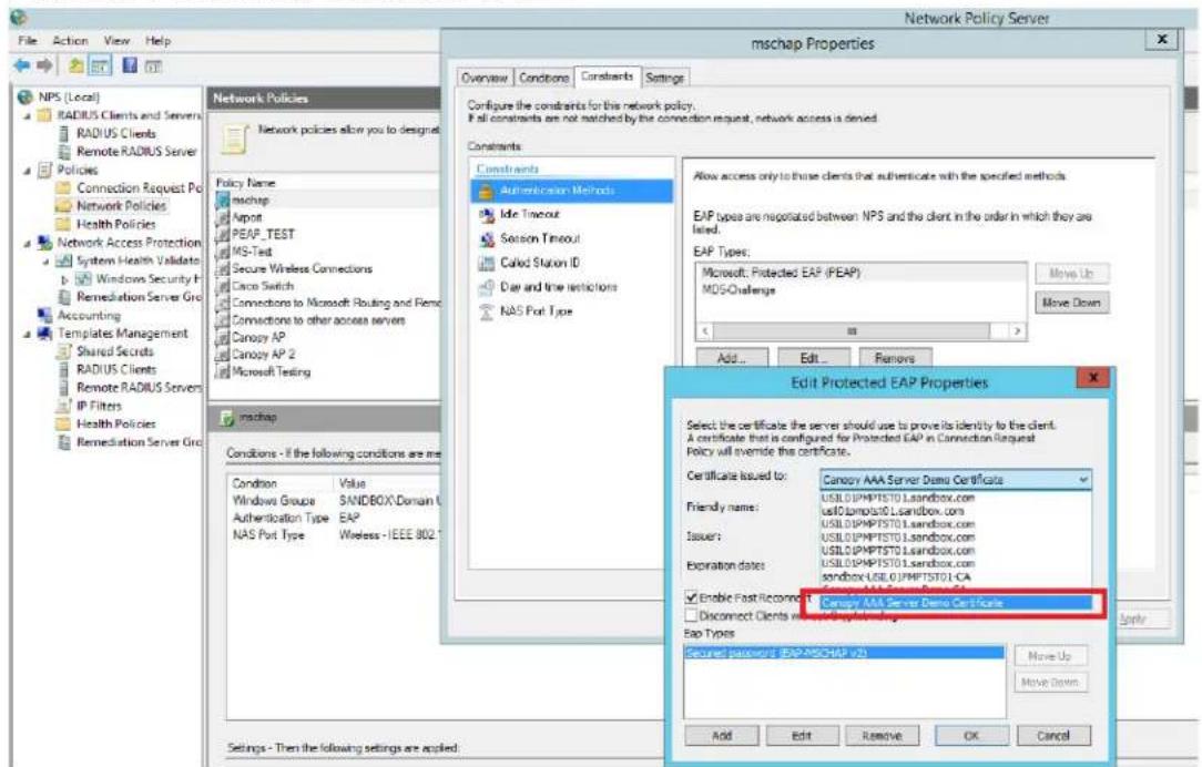
User Authentication Configuration
Enabling EAP-MD5
As mentioned earlier, Microsoft has deprecated the support for MD5 from versions of Windows. To enable MD5, the following steps to be followed:
- Follow the instructions:
https://support.microsoft.com/en-us/kb/922574/en-us?wa=wsignin1.0
Optionally, the registry file can be downloaded. It can be installed by double-click it in Windows Registry.
- From NPS Console Network Policy >
> Properties > Constrains > Authentication Method and click Add. Select MD5 and click OK.
Figure 179 Selecting MD5 from NPS console

User Configuration in Active Directory
Next open 'Active Directory Users and Computers' and create user.
Make sure user property is configured as shown below.
Figure 180 User configuration

RADIUS VSA Configuration
Before using VSA, the Cambium-Canopy-UserLevel(50) VSA must be configured with some access level say ADMIN(3).
Follow below link for configuring VSA:
https://technet.microsoft.com/en-us/library/cc731611
The Cambium's vendor code is 161.
Figure 181 RADIUS VSA configuration
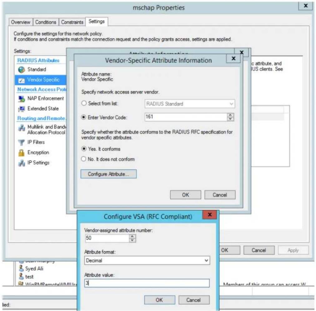
Accounting
User can enable accounting in NPS under NPS Console > Accounting > Configure Accounting.
For more details refer https://technet.microsoft.com/library/dd197475
Cisco ACS RADIUS Server Support
This briefly explains how to configure Cisco ACS RADIUS server for PEAP-MSCHAPv2 authentication.
The configuration had been tested on CISCO ACS Version : 5.7.0.15
Adding RADIUS client
Figure 182 Adding RADIUS client
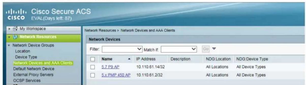
Creating Users
Figure 183 Creating users
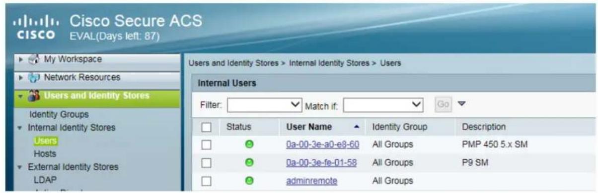
Creating RADIUS instance
Figure 184 Creating RADIUS instance

RADIUS protocols
Figure 185 RADIUS protocols
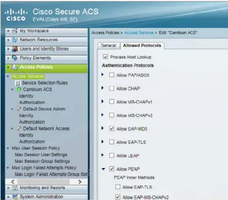
Service selection
Figure 186 Service selection
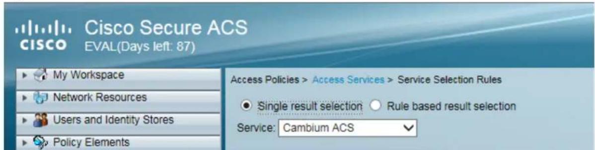
Adding Trusted CA
Figure 187 Adding Trusted CA

Note that certificate has to be in DER form, so if you have in PEM format convert using openssl.
Openssl.exe x509 -in
Installing Server Certificate
After installing trusted CA, you need to add a server certificate which will be used for TLS tunnel. Generally you have to install same certificate which is installed in your AP, so that AP can trust the radius server.
Figure 188 Installing Server Certificate

Monitoring Logs
Figure 189 Monitoring logs

Configuring VSA
Before using VSA, user has to add Cambium Vendor Specific Attribute
Navigate to System Administration > Configuration > Dictionaries > Protocols >
RADIUS > RADIUS VSA > Motorola
If Motorola is not present you can create Vendor with ID 161 and add all the VSA one by one.
Figure 190 VSA list
| Attribute | ID | Type | Direction | Multiple Allowed | |
| Cambium-Canopy-BCASTMIR | 24 | Unsigned Integer 32 | BOTH | false | |
| Cambium-Canopy-DLEL | 9 | Unsigned Integer 32 | BOTH | false | |
| Cambium-Canopy-DLER | 8 | Unsigned Integer 32 | BOTH | false | |
| Cambium-Canopy-DLMB | 27 | Unsigned Integer 32 | BOTH | false | |
| Cambium-Canopy-Gateway | 25 | IP Address | BOTH | false | |
| Cambium-Canopy-HPDLCIR | 4 | Unsigned Integer 32 | BOTH | false | |
| Cambium-Canopy-HPENABLE | 5 | Unsigned Integer 32 | BOTH | false | |
| Cambium-Canopy-HPULCIR | 3 | Unsigned Integer 32 | BOTH | false | |
| Cambium-Canopy-LPDLCIR | 2 | Unsigned Integer 32 | BOTH | false | |
| Cambium-Canopy-LPULCIR | 1 | Unsigned Integer 32 | BOTH | false | |
| Cambium-Canopy-ULEL | 7 | Unsigned Integer 32 | BOTH | false | |
| Cambium-Canopy-ULER | 6 | Unsigned Integer 32 | BOTH | false | |
| Cambium-Canopy-ULMB | 26 | Unsigned Integer 32 | BOTH | false | |
| Cambium-Canopy-UserLevel | 50 | Unsigned Integer 32 | BOTH | false | |
| Cambium-Canopy-UserMode | 51 | Unsigned Integer 32 | BOTH | false | |
| Cambium-Canopy-VLAGETO | 20 | Unsigned Integer 32 | BOTH | false | |
| Cambium-Canopy-VLFRAMES | 15 | Unsigned Integer 32 | BOTH | false | |
| Cambium-Canopy-VLIDSET | 16 | Unsigned Integer 32 | BOTH | true | |
| Cambium-Canopy-VLIGVID | 21 | Unsigned Integer 32 | BOTH | false | |
| Cambium-Canopy-VLLEARNNEN | 14 | Unsigned Integer 32 | BOTH | false | |
| Cambium-Canopy-VLMGVID | 22 | Unsigned Integer 32 | BOTH | true | |
| Cambium-Canopy-VLSMMGPASS | 23 | Unsigned Integer 32 | BOTH | false |
Using VSA for users
Navigate to Access Policies > Access Services > Cambium ACS > Authorization
1. Change condition to User name
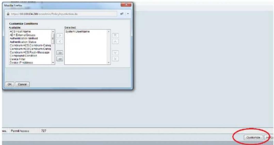
2. Next click Create and then click Select see diagram below

3. Click Create from the screen you get following screen

Chose some name and then move to RADIUS Attributes tab
4. Fill attribute which all you want for that particular user

Important: Click Add for each attribute and when done click Submit.
5. Now you are ready to use this Authorization profile for the use Select and Press OK
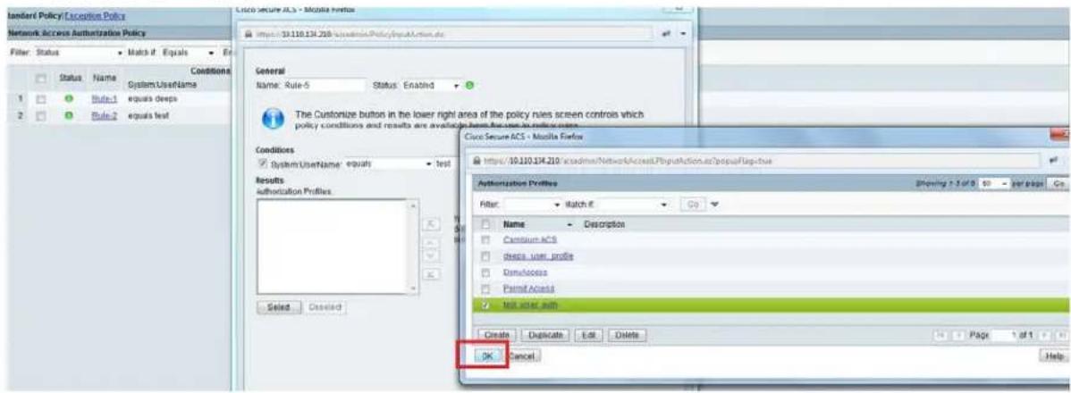
- Finally press Save Changes and you are ready to use it.
Configuring Ping Watchdog
This feature allows administrator to automatically reboot an AP/SM when there is a network issue to avoid power on reset of radios. This feature is disabled by default.
To enable Ping Watchdog feature, select the menu option Configuration > Ping Watchdog, and configure the parameters listed in the following table.
Table 203 Ping Watchdog attributes
| Ping Watchdog Configuration | |
| Ping Watchdog : | EnabledDisabled |
| IP Address To Ping : | 0.0.0.0 |
| Ping Interval : | 300 Seconds (Range: 300—86400) |
| Ping Failure Count To Reboot : | 3 (Range: 1—100) |
Save Changes
Reboot
| Attribute | Meaning |
| Ping Watchdog | This filed enables or disbales Ping Watchdog feature. |
| IP Address To Ping | This field specifies the IPV4 address of the device which needs to be pinged. |
| Ping Interval | This field specifies the time interval at which ping needs to be initiated. The time interval needs to be specified in seconds. |
| Ping Failure Count To Reboot | This field specifies the count of ping failures at which reboot needs to be initiated. |
Chapter 8: Tools
The AP and SM GUIs provide several tools to analyze the operating environment, system performance and networking, including:
• Using Spectrum Analyzer tool on page 8-2
• Using the Alignment Tool on page 8-16
• Using the Link Capacity Test tool on page 8-23
• Using AP Evaluation tool on page 8-32
• Using BHM Evaluation tool on page 8-36
• Using the OFDM Frame Calculator tool on page 8-40
• Using the Subscriber Configuration tool on page 8-45
• Using the Link Status tool on page 8-46
• Using BER Results tool on page 8-53
• Using the Sessions tool on page 8-54
• Using the Ping Test tool on page 8-55
Using Spectrum Analyzer tool
The integrated spectrum analyzer can be very useful as a tool for troubleshooting and RF planning, but is not intended to replicate the accuracy and programmability of a high-end spectrum analyzer, which sometime can be used for other purposes.
The AP/BHM and SM/BHS perform spectrum analysis together in the Sector Spectrum Analyzer tool.

Caution
On start of the Spectrum Analyzer on a module, it enters a scan mode and drops any RF connection it may have had. When choosing Start Timed Spectrum Analysis, the scan is run for time specified in the Duration configuration parameter. When choosing Start Continuous Spectrum Analysis, the scan is run continuously for 24 hours, or until stopped manually (using the Stop Spectrum Analysis button).
Any module can be used to see the frequency and power level of any detectable signal that is within, just above, or just below the frequency band range of the module.

Note
Vary the days and times when you analyze the spectrum in an area. The RF environment can change throughout the day or throughout the week.
Mapping RF Neighbor Frequencies
The neighbor frequencies can be analyzed using Spectrum Analyzer tool. Following modules allow user to:
• Use a BHS or BHM for PTP and SM or AP for PMP as a Spectrum Analyzer.
- View a graphical display that shows power level in RSSI and dBm at 5 MHz increments throughout the frequency band range, regardless of limited selections in the Custom Radio Frequency Scan Selection List parameter of the SM/BHS.
- Select an AP/BHM channel that minimizes interference from other RF equipment.

Caution
The following procedure causes the SM/BHS to drop any active RF link. If a link is dropped when the spectrum analysis begins, the link can be re-established when either a 15 minute interval has elapsed or the spectrum analyzer feature is disabled.
Temporarily deploy a SM/BHS for each frequency band range that need to monitor and access the Spectrum Analyzer tab in the Tools web page of the module.
• Using Spectrum Analyzer tool
• Using the Remote Spectrum Analyzer tool
Spectrum Analyzer tool
Analyzing the spectrum
To use the built-in spectrum analyzer functionality of the AP/SM/BH, proceed as follows:
Procedure 30 Analyzing the spectrum
1 Predetermine a power source and interface that works for the AP/SM/BH in the area to be analyzed.
2 Take the AP/SM/BH, power source and interface device to the area.
3 Access the Tools > Spectrum Analyzer web page of the AP/SM/BH.
4 Enter Duration in Timed Spectrum Analyzer Tab. Default value is 10 Seconds
5 Click Start Timed Sector Spectrum Analysis
6 The results are displayed:
Figure 191 Spectrum analysis - Results

line
| Time (s) | Value | | -------- | ----- | | 8:00 | -100 | | 8:01 | -100 | | 8:02 | -100 | | 8:03 | -100 | | 8:04 | -100 | | 8:05 | -100 | | 8:06 | -100 | | 8:07 | -100 | | 8:08 | -100 | | 8:09 | -100 | | 8:10 | -100 | | 8:11 | -100 | | 8:12 | -100 | | 8:13 | -100 | | 8:14 | -100 | | 8:15 | -100 | | 8:16 | -100 | | 8:17 | -100 | | 8:18 | -100 | | 8:19 | -100 | | 8:20 | -100 | | 8:21 | -100 | | 8:22 | -100 | | 8:23 | -100 | | 8:24 | -100 | | 8:25 | -100 | | 8:26 | -100 | | 8:27 | -100 | | 8:28 | -100 | | 8:29 | -100 | | 8:30 | -100 | | 8:31 | -100 | | 8:32 | -100 | | 8:33 | -100 | | 8:34 | -100 | | 8:35 | -100 | | 8:36 | -100 | | 8:37 | -100 | | 8:38 | -100 | | 8:39 | -100 | | 8:40 | -100 | | 8:41 | -100 | | 8:42 | -100 | | 8:43 | -100 | | 8:44 | -100 | | 8:45 | -100 | | 8:46 | -100 | | 8:47 | -100 | | 8:48 | -100 | | 8:49 | -100 | | 8:50 | -100 |
Note
AP/SM/BH scans for extra 40 seconds in addition to configured Duration
7 Travel to another location in the area to BHS.
8 Click Start Timed Spectrum Analysis
9 Repeat Steps 4 and 6 until the area has been adequately scanned and logged.
As with any other data that pertains to your business, a decision today to put the data into a retrievable database may grow in value to you over time.

Note
Wherever the operator finds the measured noise level is greater than the sensitivity of the radio that is plan to deploy, use the noise level (rather than the link budget) for your link feasibility calculations.
The AP/SM/BH perform spectrum analysis together in the Sector Spectrum Analyzer feature.
Graphical spectrum analyzer display
The AP/SM/BH display the graphical spectrum analyzer. An example of the Spectrum Analyzer page is shown in Figure 191.
The navigation feature includes:
- Results may be panned left and right through the scanned spectrum by clicking and dragging the graph left and right
• Results may be zoomed in and out using mouse
When the mouse is positioned over a bar, the receive power level, frequency, maximum and mean receive power levels are displayed above the graph
To keep the displayed data current, either set "Auto Refresh" on the module's Configuration > General.
Spectrum Analyzer page of AP
The Spectrum Analyzer page of AP is explained in Table 204.
Table 204 Spectrum Analyzer page attributes - AP
| Results | |
| Spectrum Analysis not performed. Receiver Channel Bandwidth: 40.0 MHz System time at start of analysis. Site Name: 450I AP-133 Location: No Site Location Contact: No Site Contact | |
| Display Data Path: | Both |
| Data: | File does not exist. |
| Display: | InstantaneousAveragingStop Spectrum Analysis |
| Min And Max Frequencies | |
| Min and Max Frequencies in KHz: | 5470000 5925000 (Valid Range in KHz: 4900000 - 5925000) Set Min And Max To Full Scan Set Min And Max To Center Scan +/-40MHz |
| Access Point Stats | |
| Registered SM Count: | 1 (2 Data VCs) |
| Maximum Count of Registered SMs: | 1 |
| Spectrum Analyzer Options | |
| SM Scanning Bandwidth: | 5.0 MHz |
| Note: Only SM changing channel bandwidth is currently supported. AP will scan at current channel bandwidth | |
| Timed Spectrum Analyzer | |
| Duration: | 10 Seconds (10-1000) |
| Perform Spectrum Analysis on Boot Up for One Scan: | EnableDisableStart Timed Sector Spectrum Analysis |
| Note: AP scans for extra 30 seconds | |
| Continuous Spectrum Analyzer | |
| Start Continuous Spectrum Analysis | |
| Note: Continuous Spectrum Analysis has a max of 24 hours and afterwards will automatically resume transmitting. | |
| Attribute | Meaning |
| Display Data Path | Both means that the vertical and horizontal paths are displayed or an individual path may be selected to display only a single-path reading. |
| Data | For ease of parsing data and to facilitate automation, the spectrum analyzer results may be saved as an XML file. To save the results in an XML formatted file, right-click the “SpectrumAnalysis.xml” link and save the file. |
| Display | Instantaneous means that each reading (vertical bar) is displayed with two horizontal lines above it representing the max power level received (top horizontal line) and the average power level received (lower horizontal line) at that frequency.Averaging means that each reading (vertical bar) is displayed with an associated horizontal line above it representing the max power level received at that frequency. |
| Min and Max Frequencies in KHz | Enter minimum and maximum frequencies to be scanned. |
| Set Min And Max to Full Scan | On the button press, it sets minimum and maximum allowed frequencies for scanning. |
| Set Min And Max to Center Scan +/-40 MHz | On the button press, it sets minimum and maximum frequencies to ± 40 MHz of center frequency for scanning. |
| Registered SM Count | This field displays the MAC address and Site Name of the registered SM. |
| Maximum Count of Registered SMs | This field displays the maximum number of registered SMs. |
| SM Scanning Bandwidth | This field allows to select SM's scanning bandwidth. |
| Duration | This field allows operators to configure a specified time for which the spectrum is scanned. If the entire spectrum is scanned prior to the end of the configured duration, the analyzer will restart at the beginning of the spectrum. |
| Perform Spectrum Analysis on Boot Up for One Scan | This field when enabled performs Spectrum Analysis on every boot up for one scan. |
| Continuous Spectrum Analyzer | Start Continuous Spectrum Analysis button ensures that when the SM is powered on, it automatically scans the spectrum for 10 seconds. These results may then be accessed via the Tools > Spectrum Analyzer GUI page. |
Spectrum Analyzer page of SM
The Spectrum Analyzer page of SM is explained in Table 205.
Table 205 Spectrum Analyzer page attributes - SM
| Results | |
| Spectrum Analysis not performed. Receiver Channel Bandwidth: 5.0 MHz System time at start of analysis: Site Name: 450b LG Location: No Site Location Contact: No Site Contact | |
| Display Data Path : | Both |
| Data : | File does not exist |
| Display : | Instantaneous Averaging Stop Spectrum Analysis |
| Min And Max Frequencies | |
| Min and Max Frequencies in KHz : | 5400000 5900000 (Valid Range in KHz: 4900000 - 5925000) Set Min And Max To Full Scan |
| Subscriber Module Stats | |
| Session Status : | REGISTERED VC 18 Rate 8X/6X MIMO-B VC 255 Rate 8X/4X MIMO-B |
| Registered AP : | 0a-00-3e-bb-01-77 450i AP-133 |
| Spectrum Analyzer Options | |
| Scanning Bandwidth : | 5.0 MHz |
| Timed Spectrum Analyzer | |
| Duration : | 10 Seconds (10-1000) |
| Perform Spectrum Analysis on Boot Up for One Scan : | Enable Disable |
| Power Up Mode With No 802.3 Link : | Power up in Aim Mode Power up in Operational Mode Start Timed Spectrum Analysis |
| Continuous Spectrum Analyzer | |
| Start Continuous Spectrum Analysis | |
| Note: Continuous Spectrum Analysis has a max of 24 hours and afterwards will automatically resume scanning for APs. | |
| Attribute | Meaning |
| Display Data Path | Refer Table 204 on page 8-5 |
| Data | Refer Table 204 on page 8-5 |
| Display | Refer Table 204 on page 8-5 |
| Min and Max Frequencies in KHz | To scan min to max range of frequencies, enter min and max frequencies in KHz and press Set Min and Max to Full Scan button. To scan +/- 40 MHz from center frequency, enter center frequency in KHz and press Set Min And Max To Center Scan +/- 40KHz button. |
| Registered AP | This field displays the information of AP to which this device is registered. |
| Scanning Bandwidth | This field allows to select the scanning bandwidth when running Spectrum Analysis. |
| Duration | Refer Table 204 on page 8-5 |
| Perform Spectrum Analysis on Boot Up for One Scan | This field when enabled performs Spectrum Analysis on every boot up for one scan. |
| Power Up Mode With No 802.3 Link | This field indicates whether the link has to operate in Aim mode or in operational mode on power up. |
| Continuous Spectrum Analyzer | Start Continuous Spectrum Analysis button starts the SM in Spectrum Analysis until manually stopped, or it has scanned for 24 hours. |
Spectrum Analyzer page of BHM
The Spectrum Analyzer page of BHM is explained in Table 206.
Table 206 Spectrum Analyzer page attributes - BHM
| Results Spectrum Analysis not performed. Receiver Channel Bandwidth: 40.0 MHz System time at start of analysis: Site Name: Location: No Site Location Contact: No Site Contact | |
| Display Data Path: | Both File does not exist. Instantaneous Averaging Stop Spectrum Analysis |
| Data: | |
| Display: | |
| Min And Max Frequencies Min and Max Frequencies in KHz: | 5470000 5925000 (Valid Range in KHz: 4900000 - 5925000) Set Min And Max To Full Scan Set Min And Max To Center Scan +/-40MHz |
| Backhaul Stats Timing Slave Status: | Connected |
| Spectrum Analyzer Options BHS Scanning Bandwidth: | 5.0 MHz Note: Only BHS changing channel bandwidth is currently supported. BHM will scan at current channel bandwidth |
| Timed Spectrum Analyzer Duration: | 10 Seconds (10-1000) Enable Disable Start Timed Sector Spectrum Analysis |
| Perform Spectrum Analysis on Boot Up for One Scan: | |
| Note: BHM scans for extra 30 seconds | |
| Continuous Spectrum Analyzer Start: Continuous Spectrum Analyss Note: Continuous Spectrum Analysis has a max of 24 hours and afterwards will automatically resume transmitting. | |
| Attribute | Meaning |
| Data | Refer Table 204 on page 8-5 |
| Display | Refer Table 204 on page 8-5 |
| Duration | Refer Table 204 on page 8-5 |
| Min and Max Frequencies in KHz | Enter minimum and maximum frequencies to be scanned. |
| Set Min And Max to Full Scan | On the button press, it sets minimum and maximum allowed frequencies for scanning. |
| Set Min And Max to Center Scan +/-40 MHz | On the button press, it sets minimum and maximum frequencies to ± 40 MHz of center frequency for scanning. |
| Timing Slave Status | This field displays the status of any registered Timing Slave. |
| BHS Scanning Bandwidth | This field allows to select BHS's scanning bandwidth. |
| Duration | This field allows operators to configure a specified time for which the spectrum is scanned. If the entire spectrum is scanned prior to the end of the configured duration, the analyzer will restart at the beginning of the spectrum. |
| Perform Spectrum Analysis on Boot Up for One Scan | This field when enabled performs Spectrum Analysis on every boot up for one scan. |
| Continuous Spectrum Analyzer | Start Continuous Spectrum Analysis button starts the SM in Spectrum Analysis until manually stopped, or it has scanned for 24 hours. |
Spectrum Analyzer page of BHS
The Spectrum Analyzer page of BHS is explained in Table 207.
Table 207 Spectrum Analyzer page attributes - BHS

| Attribute | Meaning |
| Data | Refer Table 204 on page 8-5 |
| Display | Refer Table 204 on page 8-5 |
| Session Status | This field displays current session status and rates. The session states can be Scanning, Syncing, Registering or Registered. |
| Registered Backhaul | This field displays MAC address of BHM and PTP model number |
| Duration | Refer Table 204 on page 8-5 |
| Perform Spectrum Analysis on Boot Up for one scan | This field allows to Enable or Disable to start Spectrum Analysis on boot up of module for one scan. |
Continuous
Refer Table 204 on page 8-5
Spectrum Analyzer
Spectrum Analyzer page result of PMP 450 SM
Figure 192 Spectrum Analyzer page result - PMP 450 SM

bar
| Time (s) | Value | | :--- | :--- | | 5470.0 | -52 | | 5492.5 | -55 | | 5515.0 | -88 | | 5537.5 | -88 | | 5560.0 | -88 | | 5582.5 | -88 | | 5605.0 | -88 | | 5627.5 | -88 | | 5650.0 | -88 | | 5672.5 | -88 | | 5695.0 | -88 | | 5717.5 | -88 | | 5740.0 | -72 | | 5762.5 | -72 | | 5785.0 | -72 | | 5807.5 | -72 | | 5830.0 | -72 | | 5852.5 | -72 | | 5875.0 | -72 | | 5890.0 | -72 |




Remote Spectrum Analyzer tool
The Remote Spectrum Analyzer tool in the AP/BHM provides additional flexibility in the use of the spectrum analyzer in the SM/BHS. Set the duration of 10 to 1000 seconds, then click the Start Remote Spectrum Analysis button to launch the analysis from that SM/BHS.
In PMP configuration, a SM must be selected from the drop-down list before launching Start Remote Spectrum Analysis.
Analyzing the spectrum remotely
Procedure 31 Remote Spectrum Analyzer procedure
1 The AP/BHM de-registers the target SM/BHS.
2 The SM/BHS scans (for the duration set in the AP/BHM tool) to collect data for the bar graph.
3 The SM/BHS re-registers to the AP/BHM.
4 The AP/BHM displays the bar graph.
The bar graph is an HTML file, but can be changed to an XML file, which is then easy to analyze using scripts that you may write for parsing the data. To transform the file to XML, click the "SpectrumAnalysis.xml" link below the spectrum results. Although the resulting display appears mostly unchanged, the bar graph is now coded in XML. You can now right-click on the bar graph for a Save Target As option to save the Spectrum Analysis.xml file.
Remote Spectrum Analyzer page of AP
The Remote Spectrum Analyzer page of AP is explained in Table 208.
Table 208 Remote Spectrum Analyzer attributes - AP
| Access Point Stats | |
| Registered SM Count : | 1 (1 Data VCs) |
| Maximum Count of Registered SMs : | 1 |
| Configuration | |
| Current Subscriber Module : | Site Name [0a003ebb0104] Luid: 2 ▼ |
| Duration : | 10 Seconds (10—1000) |
| Scanning Bandwidth : | 5.0 MHz ▼ |
| Start Remote Spectrum Analysis | |
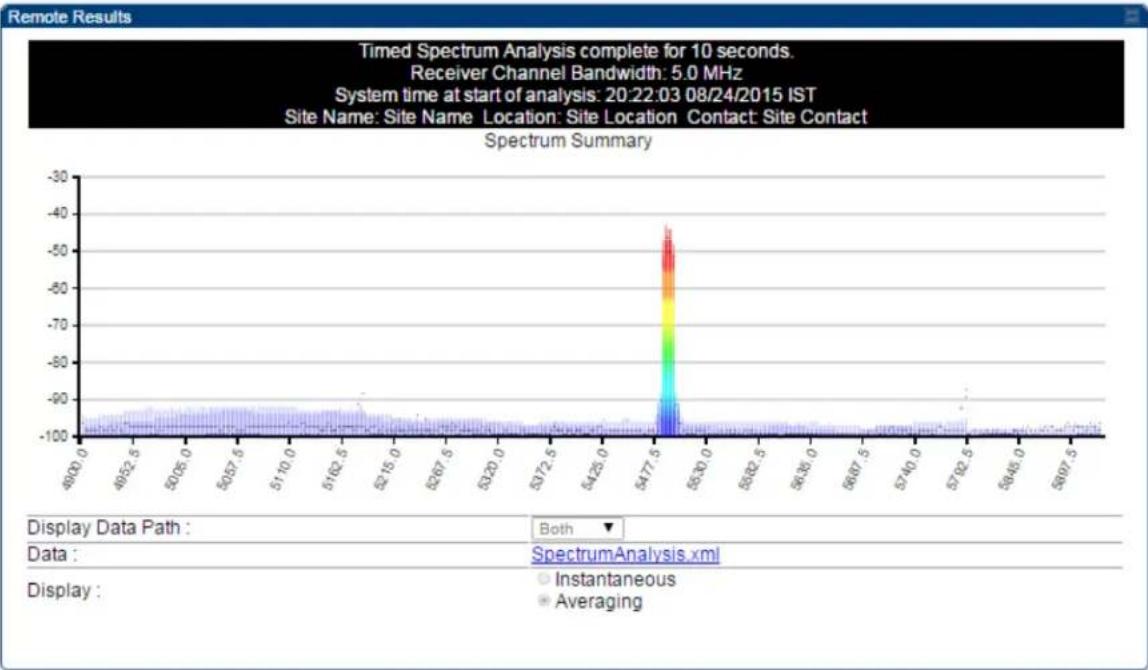
line
| Time (s) | Value | | -------- | ----- | | 5477.5 | -45 || Attribute | Meaning |
| Registered SM Count | This field displays the number of SMs that were registered to the AP before the SA was started. This helps the user know all the SMs re-registered after performing a SA. |
| Maximum Count of Registered SMs | This field displays the largest number of SMs that have been simultaneously registered in the AP since it was last rebooted. This count can provide some insight into sector history and provide comparison between current and maximum SM counts at a glance. |
| Current Subscriber Module | The SM with which the Link Capacity Test is run. |
| Duration | This field allows operators to configure a specified time for which the spectrum is scanned. If the entire spectrum is scanned prior to the end of the configured duration, the analyzer will restart at the beginning of the spectrum. |
| Scanning Bandwidth | This parameter defines the size of the channel scanned when running the analyzer. |
Remote Spectrum Analyzer page of BHM
The Remote Spectrum Analyzer page of BHM is explained in Table 209.
Table 209 Remote Spectrum Analyzer attributes - BHM

line
| Frequency | Value | | --------- | ----- | | 5470.0 | -100 | | 5492.5 | -47 | | 5515.0 | -100 | | 5537.5 | -100 | | 5560.0 | -100 | | 5582.5 | -100 | | 5605.0 | -100 | | 5627.5 | -100 | | 5650.0 | -100 | | 5672.5 | -100 | | 5695.0 | -100 | | 5717.5 | -100 | | 5740.0 | -100 | | 5762.5 | -100 | | 5785.0 | -100 | | 5807.5 | -100 | | 5830.0 | -100 | | 5852.5 | -100 | | 5875.0 | -100 | | 5897.5 | -100 || Attribute | Meaning |
| Duration | Refer Table 204 on page 8-5 |
Using the Alignment Tool
The SM's or BHS's Alignment Tool may be used to maximize Receive Power Level, Signal Strength Ratio and Signal to Noise Ratio to ensure a stable link. The Tool provides color coded readings to facilitate in judging link quality.

Note
To get best performance of the link, the user has to ensure the maximum Receive Power Level during alignment by pointing correctly. The proper alignment is important to prevent interference in other cells. The achieving Receive Power Level green (> - 70 dBm) is not sufficient for the link.
Figure 193 Alignment Tool tab of SM - Receive Power Level > -70 dBm
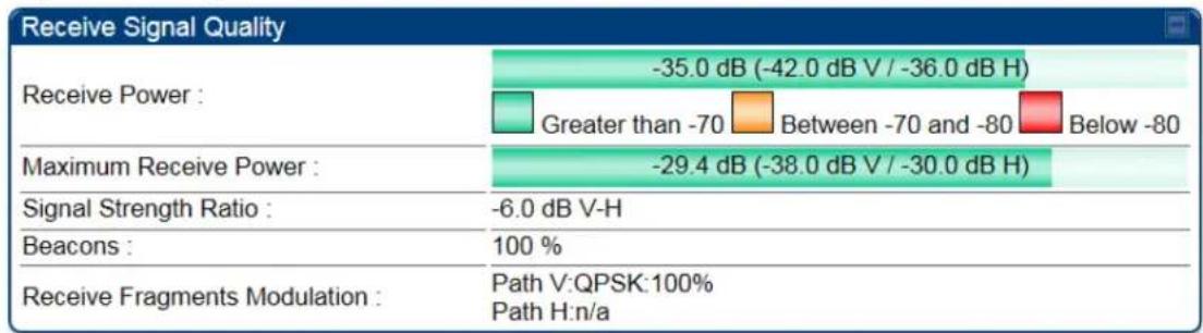
Figure 194 Alignment Tool tab of SM - Receive Power Level between -70 to -80 dBm
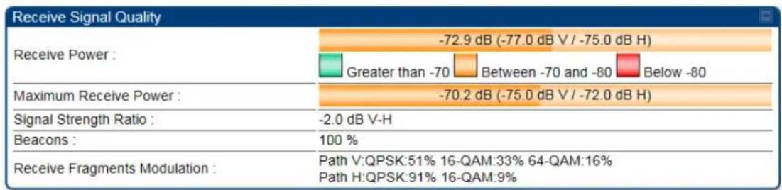
Figure 195 Alignment Tool tab of SM - Receive Power Level < -80 dBm
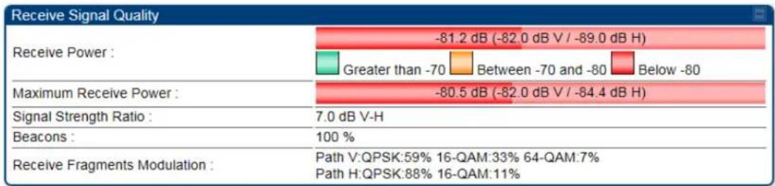
Aiming page and Diagnostic LED - SM/BHS
The SM's/BHS's Alignment Tool (located in GUI Tools -> Aiming) may be used to configure the SM's/BHS's LED panel to indicate received signal strength and to display decoded beacon information/power levels. The SM/BHS LEDs provide different status based on the mode of the SM/BHS. A SM/BHS in "operating" mode will register and pass traffic normally. A SM/BHS in "aiming" mode will not register or pass traffic, but will display (via LED panel) the strength of received radio signals (based on radio channel selected via Tools ->Aiming). See SM/BHS LEDs on page 2-21.

Note
For accurate power level readings to be displayed, traffic must be present on the radio link.
Refer Table 25 SM/BHS LED descriptions on page 2-22 for SM/BHS LED details.
Aiming page of SM
The Aiming page is similar to Spectrum Analyzer where it scans the spectrum but it does not establish any session with any APs. It has two modes - Single Frequency Only and Normal Frequency Scan List.
The Aiming page of SM is explained in Table 210.
Table 210 Aiming page attributes - SM
| Tools → Aiming 5.4/5.7GHz MIMO OFDM - Subscriber Module - 0a-00-3e-a0-a0-66 Alignment mode | |
| Aiming Configuration | |
| Aiming Mode: | Single Frequency OnlyNormal Frequency Scan ListNote: No beacon information is decoded for 'Single Frequency Only' mode |
| Single Frequency: | None *Enable Aiming Mode Disable Aiming ModeAiming Mode will be enabled for 15 minutes or until disabled. |
| Aiming Status | |
| Current Status: | SM is in Alignment Mode for selected frequencies |
| Aiming Results | |
| Current entry: Frequency: 5745.000 MHz Power: -31.9 (-50.0 V / -32.0 H) dBm Users: 1 ESN: 0a-00-3e-a1-35-75 Color Code: 0 Multipoint | |
| Other entries: Frequency: 5680.000 MHz Power: -36.5 (-42.0 V / -38.0 H) dBm ESN: 0a-00-3e-a0-aa-9a Color Code: Backhaul | |
| Frequency: 5740.000 MHz Power: -77.8 (-91.0 V / -78.0 H) dBm Users: 2 ESN: 0a-00-3e-a0-08-08 Color Code: 0 Multipoint | |
| Attribute | Meaning |
| Aiming Mode | Single Frequency Only: scans only selected single frequency. Normal Frequency Scan List: scans: scans all frequency of scan list. |
| Single Frequency | Select a particular frequency from drop-down menu for scanning. |
| Scan Radio Frequency Only Mode | Enabled: the radio is configured to "aiming" or "alignment" mode, wherein the LED panel displays an indication of receive power level. See Table 25 SM/BHS LED descriptions on page 2-22. Disabled: the radio is configured to "operating" mode, wherein the SM registers and passes traffic normally. |
| Aiming Results | The Aiming Results are displayed in two sections - Current entry and Other entries. Frequency: this field indicates the frequency of the AP which is transmitting the beacon information. |
Power: This field indicates the current receive power level (vertical channel) for the frequency configured in parameter Radio Frequency.
Users: This field indicates the number of SMs currently registered to the AP which is transmitting the beacon information.
ESN: This field indicates the MAC, or hardware address of the AP/BHM which is transmitting the beacon information.
Color Code: This field displays a value from 0 to 254 indicating the AP's configured color code. For registration to occur, the color code of the SM and the AP must match. Color code is not a security feature. Instead, color code is a management feature, typically for assigning each sector a different color code.
Color code allows you to force a SM to register to only a specific AP, even where the SM can communicate with multiple APs. The default setting for the color code value is 0. This value matches only the color code of 0 (not all 255 color codes).
Multipoint or Backhaul: this field indicates type of configuration - point-Multipoint(PMP) or Backhaul (PTP).
Aiming page of BHS
The Alignment page of BHS is explained in Table 211.
Table 211 Aiming page attributes - BHS
| Alignment mode | |
| Aiming Configuration | |
| Aiming Mode : | Single Frequency OnlyNormal Frequency Scan ListNote: No beacon information is decoded for 'Single Frequency Only' mode |
| Single Frequency : | NoneEnable Aiming Mode Disable Aiming ModeAiming Mode will be enabled for 15 minutes or until disabled. |
| Aiming Status | |
| Current Status : | BHS is in Alignment Mode for selected frequencies |
| Aiming Results | |
| No Backhauls available and visible which match current configuration. Other entries:Frequency: 5680.000 MHzPower: -27.0 (-30.0 V / -30.0 H) dBmUsers: 0ESN: 0a-00-3e-a0-aa-9aColor Code: 5Backhaul | |
| Attribute | Meaning |
| Refer | |
| Refer Table 210 Aiming page attributes - SM for attribute details. | |
Alignment Tone
For coarse alignment of the SM/BHS, use the Alignment Tool located at Tools -> Alignment Tool. Optionally, connect a headset alignment tone kit to the AUX/SYNC port of the SM/BHS and listen to the alignment tone, which indicates greater SM/BHS receive signal power by pitch. By adjusting the SM's/BHS's position until the highest frequency pitch is obtained operators and installers can be confident that the SM/BHS is properly positioned. For information on device GUI tools available for alignment, see sections Aiming page and Diagnostic LED - SM/BHS on page 8-17, Using the Link Capacity Test tool on page 8-23 and Using AP Evaluation tool on page 8-32.
Figure 196 PMP/PTP 450i Series link alignment tone


Note
The Alignment Tone cable for a 450i Series uses an RJ-45 to headset cable whereas the 450 Series alignment tone cable uses an RJ-12 to headset cable.
Alignment Tool Headset and alignment tone adapters can be ordered from Cambium and Best-Tronics (http://btpa.com/Cambium-Products/) respectively using the following part numbers:
Table 212 Alignment Tool Headsets and Alignment tone adapter third party product details
| Reference | Product description |
| ACATHS-01A | Alignment tool headset for the PMP/PTP 450 and 450i Series products |
| BT-1277 | Headset alignment cable (RJ-45) for the PMP/PTP 450i Series products |
| BT-0674 | Headset alignment cable (RJ-12) for the PMP/PTP 450 Series products. |
Using the Link Capacity Test tool
The Link Capacity Test tab allows you to measure the throughput and efficiency of the RF link between two modules. Many factors, including packet length, affect throughput.
The Link Capacity Test tool has following modes:
- Link Test with Multiple VCs: Tests radio-to-radio communication across selected or all registered VCs, but does not bridge traffic (PMP 450m Series AP only).
- Link Test without Bridging: Tests radio-to-radio communication, but does not bridge traffic.
- Link Test with Bridging: Bridges traffic to “simulated” Ethernet ports, providing a status of the bridged link.
- Link Test with Bridging and MIR: Bridges the traffic during test and also adheres to any MIR (Maximum Information Rate) settings for the link.
- Extrapolated Link Test: Estimates the link capacity by sending few packets and measuring link quality.
The Link Capacity Test tab contains the settable parameter Packet Length with a range of 64 to 1714 bytes. This allows you to compare throughput levels that result from various packet sizes.
The Current Results Status also displayed date and time of last performed Link Capacity Test. If there is any change in time zone, the date and time will be adjusted accordingly.

Note
The Extrapolated Link Test can be run by Read-Only login also.
Performing Link Test
The link test is a tool that allows the user to test the performance of the RF link. Packets are added to one or more queues in the AP in order to fill the frame. Throughput and efficiency are then calculated during the test. The 450 and 450i APs offer link test options to one SM at a time. The 450m AP offers the option of a link test to multiple VCs at the same time. This allows the user to test throughput in MU-MIMO mode, in which multiple SMs are served at the same time.
This new link test can be found under Tools > Link Capacity Test
Link Test with Multiple LUIDs

Note
The "Link Test with Multiple LUIDs" Link Capacity Test is supported for PMP 450m Series AP only.
Figure 197 Link Capacity Test - PMP 450m Series AP

Procedure 32 Performing a Link Capacity Test - Link Test with Multiple LUIDs
Link Test Configurations parameters
1 Access the Link Capacity Test tab in the Tools web page of the module.
2 Set Link with Multiple Data Channels attribute to Link Test Low Priority Data Channels, Link Test Low and Medium Priority Data Channels, Link Test Low, Medium and High Priority Data Channels, or Link Test All Data Channels.
3 Set the MU-MIMO attribute to Enabled or Disabled.
Note: The MU-MIMO feature is enabled on the Low Priority Data Channel only
4 Set the Ignore Configured CIR attribute to Enabled or Disabled.
5 Set the User Traffic During Link Test attribute to Block User Traffic or Allow User Traffic.
Link Test Settings parameters
6 Enter LUID List (applicable for PMP 450m AP only)
The Current Subscriber Module and LUID List are valid only when selecting Link Test with Multiple LUIDs.
- Current Subscriber Module: select the LUID to perform the link test with
- LUID list: select a list or range of LUIDs to include in the link test with multiple LUIDs
If left blank, all LUIDs will be included in the link test
7 Type into the Duration field how long (in seconds) the RF link must be tested.
8 Select the Direction attribute to Bi-directional, Uplink Only, or Downlink Only.
9 Type into the Number of Packets field a value of 0 to flood the link for the duration of the test.
10 Type into the Packet Length field a value of 1518 to send 1518-byte packets during the test.
11 Click the Start Test button.
Figure 198 Link Test with Multiple LUIDs (1714-byte packet length)
Current Results Status
| Test Duration: 10 Pkt Length: 1714 Test Direction Bi-DirectionalNote: Some SMs did not respond with Uplink data or do not support Uplink/Bi-directional flood test (Release 16.0 or higher required). This may affect throughput results. |
Link Test with Multiple LUIDs
Flood Test Summary
| Throughput | Average Group Size | |||
| Downlink | Uplink | Aggregate | Downlink | Uplink |
| 109.82 Mbps | 89.35 Mbps | 109.18 Mbps | 2.0 | 2.0 |
Detailed Flood Test Statistics
| Subscriber Module | LUID | Data Channel Priority | Tested | Throughput | Efficiency | Average Rate | Grouping Ratio | ||||
| Downlink | Uplink | Downlink | Uplink | ||||||||
| 109.82 Mbps | 89.35 Mbps | 99% | 98% | Transmit | Receive | Downlink | Uplink | ||||
| SM4 21 - (0a-00-3a-b4-d3-3G) | 002 | Low | Yes | 6.10 Mbps | 6.09 Mbps | 97% | 99% | 3.9X | 3.7X | 98% | 99% |
| SM1 11 - (0a-00-3e-b4-24-1g) | 003 | Low | Yes | 15.53 Mbps | 0 bps | 99% | 0% | 8.0X | 0.0X | 100% | 0% |
| SM7 23 - (0a-00-3a-b4-c2-5c) | 004 | Low | Yes | 12.36 Mbps | 8.73 Mbps | 99% | 99% | 7.9X | 5.3X | 99% | 99% |
| SM5 24 - (0a-00-3a-b4-d2-fe) | 005 | Low | Yes | 12.35 Mbps | 8.71 Mbps | 99% | 100% | 7.9X | 5.3X | 100% | 99% |
| SM8 25 - (0a-00-3a-b4-c2-65) | 006 | Low | Yes | 12.37 Mbps | 11.63 Mbps | 100% | 98% | 7.9X | 7.1X | 100% | 99% |
| SM3 13 - (0a-00-3a-b4-d2-e0) | 007 | Low | Yes | 7.83 Mbps | 10.41 Mbps | 100% | 100% | 4.0X | 3.8X | 99% | 99% |
| SM2 12 - (0a-00-3a-b4-24-08) | 008 | Low | Yes | 15.35 Mbps | 17.55 Mbps | 99% | 97% | 7.9X | 6.4X | 99% | 99% |
| SM6 22 - (0a-00-3a-b4-d2-fl) | 009 | Low | Yes | 12.35 Mbps | 8.72 Mbps | 99% | 100% | 7.9X | 5.3X | 99% | 99% |
| SM15 - (0a-00-3e-b4-d2-c9) | 012 | Low | Yes | 15.54 Mbps | 17.47 Mbps | 100% | 98% | 8.0X | 6.4X | 100% | 99% |
Slot Grouping
| Group Size | % Downlink Distribution | % Uplink Distribution |
| 1 (ungrouped) | 0.0 | 0.1 |
| 2 | 100.0 | 99.9 |
| 3 | 0.0 | 0.0 |
| 4 | 0.0 | 0.0 |
| 5 | 0.0 | 0.0 |
| 6 | 0.0 | 0.0 |
| 7 | 0.0 | 0.0 |
Link Test ran on 18:41:29 10/23/2018 UTC
Link Test without Bridging, Link Test with Bridging or Link Test with Bridging and MIR
Figure 199 Link Test without Bridging


Figure 200 Link Test with Bridging and MIR

Refer Link Test with Multiple on page 8-24 for Link Test procedure.
Figure 201 Link Test without Bridging (1518-byte packet length)
| Data Channel Priority | Downlink | Uplink | Aggregate | Packet Transmit | Packet Receive | |||
| Actual | Actual | |||||||
| Low | 22.70 Mbps | 24.51 Mbps | 47.21 Mbps, 3841 pps | 9232 (1846 pps) | 9977 (1995 pps) | |||
| Efficiency | ||||||||
| Downlink | Uplink | |||||||
| Efficiency | Fragments count | Signal to Noise Ratio | Efficiency | Fragments count | Signal to Noise Ratio | |||
| Actual | Missed | Actual | Missed | |||||
| 99% | 221728 | 42 | 39 dB V 36 dB H | 99% | 239552 | 127 | 35 dB V 39 dB H | |
| Link Quality Downlink | ||||||||
| RF Path | Modulation | Fragments | Modulation Percentage | Average Corrected Bit Errors | ||||
| V | QPSK | 27701 | 25% | 0.378 | ||||
| V | 16-QAM | 27702 | 25% | 0.613 | ||||
| V | 64-QAM | 27701 | 25% | 0.941 | ||||
| V | 256-QAM | 27700 | 25% | 0.519 | ||||
| H | QPSK | 27697 | 25% | 1.719 | ||||
| H | 16-QAM | 27694 | 25% | 2.487 | ||||
| H | 64-QAM | 27675 | 25% | 3.287 | ||||
| H | 256-QAM | 27698 | 25% | 1.595 | ||||
| Uplink | ||||||||
| RF Path | Modulation | Fragments | Modulation Percentage | Average Corrected Bit Errors | ||||
| V | 256-QAM | 118324 | 100% | 3.569 | ||||
| H | 256-QAM | 119788 | 100% | 0.753 | ||||
Performing Extrapolated Link Test
The Extrapolated Link Test estimates the link capacity by sending few packets and measuring link quality. Once the test is initiated, the radio starts session at the lower modulation, 1X, as traffic is passed successfully across the link, the radio decides to try the next modulation, 2X. This process repeats until it finds best throughput to estimate capacity of link.
The procedure for performing Extrapolated Link Test is as follows:
Procedure 33 Performing an Extrapolated Link Test
1 Access the Link Capacity Test tab in the Tools web page of the module.
2 Select Link Test Mode Extrapolated Link Test
3 Click the Start Test button.
4 In the Current Results Status block of this tab, view the results of the test.
Figure 202 Extrapolated Link Test results
| Extrapolated Link Test | |||||||
| Downlink | Uplink | Aggregate | |||||
| 31.94 Mbps | 32.76 Mbps | 64.71 Mbps | |||||
| Transmit modulation Down: 4X Up: 4X Efficiencies Down:100 Up:100 Slots carrying data: Downlink/Uplink: 39/40 | |||||||
| Note: Extrapolated Link Test just sends over a few packets measuring their quality and extrapolates that to what the expected throughput would be. This is just an approximation to have minimal service impact. Efficiency | |||||||
| Efficiency | Downlink | Uplink | |||||
| Actual | Fragments count | Signal to Noise Ratio | Efficiency | Fragments count | Signal to Noise Ratio | ||
| Actual | Missed | ||||||
| 100% | 6831 | 0 | 22 dB V 22 dB H | 100% | 6831 | 0 | 20 dB V 20 dB H |
| Link Quality Downlink | |||||||
| RF Path | Modulation | Fragments | Modulation Percentage | Average Corrected Bit Errors | |||
| V | QPSK | 1708 | 50% | 0.000 | |||
| V | 16-QAM | 1709 | 50% | 0.000 | |||
| H | QPSK | 1707 | 50% | 0.000 | |||
| H | 16-QAM | 1707 | 50% | 0.000 | |||
| Uplink | |||||||
| RF Path | Modulation | Fragments | Modulation Percentage | Average Corrected Bit Errors | |||
| V | 16-QAM | 3420 | 100% | 0.013 | |||
| H | 16-QAM | 3420 | 100% | 0.000 | |||
Link Capacity Test page of AP
The Link Capacity Test page of AP is explained in Table 213.
Table 213 Link Capacity Test page attributes - 450m AP
| Link Test Configurations | |
| Link Test Mode : | Link Test with Bridging and MIR ▼ |
| Signal to Noise Ratio Calculation during Link Test : | EnabledDisabled |
| SM Link Test Mode Restriction : | EnabledDisabled |
| Link Test with All Available Data Channels : | All Available Data ChannelsLow Priority Channel onlyNote: All Available Data Channels option requires that the SM already has at least one additional data channel enabled. |
| MU-MIMO : | EnabledDisabled |
| Display results for untested Data Channels : | EnabledDisabled |
| Ignore Configured CIR : | EnabledDisabled |
| Link Test Settings | |
| Current Subscriber Module : | Idle [0a003ebb41d2] Luid: 2 |
| LUID List : | (eg. 2 — 22,24,32) Empty field or 0 will flood all registered LUIDs for duration of test |
| Duration : | 2 Seconds (2 — 10) |
| Direction : | Bi-directional |
| Number of Packets : | 0 (0 — 64) Zero will flood the link for duration of test |
| Packet Length : | 1714 Bytes (64 — 1714 bytes)Start Test |
| Attribute | Meaning |
| Link Test Mode | Select Link Test Mode from drop-down menu:• Link Test with Multiple LUIDs (PMP 450m Series AP only)• Link Test without Bridging• Link Test with Bridging• Link Test with Bridging and MIR• Extrapolated Link Test |
| Signal to Noise Ratio Calculation during Link Test | Enable this attribute to display Signal-to-Noise information for the downlink and uplink when running the link test. |
| SM Link Test Mode Restriction | Enable this parameter to restrict SM link test mode. |
| Link Test with All Available Data Channels | This parameter is used to enable or disable usage of either all available data channels or low priority data channel only during the link test. |
| MU-MIMO | This parameter determines whether the DL flood test packets use MU-MIMO grouping or not.Note: This field is applicable only when the “Link Test Mode” field is set to “Link Test with Multiple VC’s” option.Note: This field is applicable for PMP 450m APs only. |
| Display results for untested Data Channels | If “Link test with multiple VC’s” is run and a subset of registered VC’s enters into the VC List field, then enabling this field produces a table that displays results for VC’s with traffic which are in session; but not tested as part of the link test.Note: This field is applicable for PMP 450m flood tests only. |
| Ignore Configured CIR | Enable this parameter to schedule flood data regardless of the CIR configuration for each SM. |
| Current Subscriber Module | The SM with which the Link Capacity Test is run. This field is only applicable for AP (not SM page). |
| LUID List | This field is displayed for PMP 450m Series AP. It is only applicable for “Link Test with Multiple LUIDs” Test mode.Enter LUID List (e.g. 18 or above for low priority LUIDs and 255 or above for high priority LUIDs or 0 for all registered LUIDs) which needs to be used for link test traffic. |
| Duration | This field allows operators to configure a specified time for which the spectrum is scanned. If the entire spectrum is scanned prior to the end of the configured duration, the analyzer will restart at the beginning of the spectrum. |
| Direction | Configure the direction of the link test. Specify Downlink or Uplink to run the test only in the corresponding direction only. Specific Bi-Directional to run the test in both directions. |
| Number of Packets | The total number of packets to be sent during the Link Capacity Test. When Link Test Mode is set to Link Test Without Bridging this field is not configurable. |
| Packet Length | The size of the packets in Bytes to send during the Link Capacity Test |
Link Capacity Test page of BHM/BHS/SM
The Link Capacity Test page of BHM/BHS is explained in Table 214.
Table 214 Link Capacity Test page attributes - BHM/BHS
| Link Test Configurations | |
| Link Test Mode : | Link Test without Bridging |
| Signal to Noise Ratio Calculation during Link Test : | EnabledDisabled |
| Link Test with All Available Data Channels : | All Available Data ChannelsLow Priority Channel onlyNote: All Available Data Channels option requires that the SM already has at least one additional data channel enabled. |
| Link Test Settings | |
| Duration : | 2 Seconds (2 — 10) |
| Direction : | Bi-directional ▼ |
| Number of Packets : | 0 (0 — 64) Zero will flood the link for duration of test |
| Packet Length : | 1714 Bytes (64 — 1714 bytes)Start Test |
| Attribute | Meaning |
| Link Test Mode | See Table 213 on page 8-29 |
| Signal to Noise Ratio Calculation during Link Test | See Table 213 on page 8-29 |
| Link Test with All Available Data Channels | See Table 213 on page 8-29 |
| Duration | See Table 213 on page 8-29 |
| Direction | See Table 213 on page 8-29 |
| Number of Packets | See Table 213 on page 8-29 |
| Packet Length | See Table 213 on page 8-29 |
Using AP Evaluation tool
The AP Evaluation tab on Tools web page of the SM provides information about the AP that the SM sees.

Note
The data for this page may be suppressed by the SM Display of AP Evaluation Data setting in the Configuration > Security tab of the AP.
The AP Eval results can be accessed via SNMP and config file.
AP Evaluation page
The AP Evaluation page of AP is explained in Table 215.
Table 215 AP Evaluation tab attributes - AP
| AP List |
| AP Selection Method used: Optimize for Throughput |
| Current entry index: 0 Session Status: REGISTERED (via Primary Color Code 254) |
| ********** |
| Index: 0 Frequency: 5490.000 MHz Channel Bandwidth: 10.0 MHz Cyclic Prefix: 1/16 |
| ESN: 0a-00-3e-bb-00-fb Region: Other |
| Beacon Receive Power: -46.0 (-49.0 V / -49.0 H) dBm Beacon Count: 18 FECEn: 1 |
| Type: Multipoint Avail: 1 Age: 0 Lockout: 0 RegFail 0 Range: 0 feet MaxRange: 2 miles TxBER: 1 EBcast: 0 |
| Session Count: 6 NoLUIDS: 0 OutOfRange: 0 AuthFail: 0 EncryptFail: 0 Rescan Req: 0 SMLimitReached: 0 |
| NoVC's: 0 VCRsv/430smFail: 0 VCActFail: 0 |
| AP Gain: -10 dBm AP RcvT: -55 dBm SectorID: 0 Color Code: 254 BeaconVersion: 1 SectorUserCount: 0 |
| SyncSrc: 0 |
| NumULSlots: 9 NumDLSlots: 26 NumULContSlots: 4 |
| WhiteSched: 0 ICC: 0 Authentication: Disabled |
| SM PPPoE: Supported |
| Frame Period:2.5 ms |
| Beacon Statistics | |
| Unsupported Feature Beacon Received : | 0 |
| Unknown Feature Beacon Received : | 0 |
| Old Version Beacon Received : | 0 |
| Wrong Frequency Beacon Received : | 0 |
| Non Lite Beacon Received : | 0 |
| Attribute | Meaning |
| Index | This field displays the index value that the system assigns (for only this page) to the AP where this SM is registered. |
| Frequency | This field displays the frequency that the AP transmits. |
| Channel Bandwidth | The channel size used by the radio for RF transmission. The setting for the channel bandwidth must match between the AP and the SM. |
| Cyclic Prefix | OFDM technology uses a cyclic prefix, where a portion of the end of a symbol (slot) is repeated at the beginning of the symbol to allow multi-pathing to settle before receiving the desired data. A 1/16 cyclic prefixes mean that for every 16 bits of throughput data transmitted, an additional bit is used. The Cyclic Prefix 1/16 only can be selected at this time. |
| ESN | This field displays the MAC address (electronic serial number) of the AP. For operator convenience during SM aiming, this tab retains each detected ESN for up to 15 minutes. If the broadcast frequency of a detected AP changes during a 15-minute interval in the aiming operation, then a multiple instance of the same ESN is possible in the list. Eventually, the earlier instance expires and disappears and the later instance remains to the end of its interval, but you can ignore the early instance(s) whenever two or more are present. |
| Region | This field displays the AP's configured Country Code setting. |
| Power Level | This field displays the SM's combined received power level from the AP's transmission. |
| Beacon Count A count of the beacons seen in a given time period. | |
| FECEn | This field contains the SNMP value from the AP that indicates whether the Forward Error Correction feature is enabled.0: FEC is disabled1: FEC is enabled |
| Type | Multipoint indicates that the listing is for an AP. |
| Age | This is a counter for the number of minutes that the AP has been inactive. At 15 minutes of inactivity for the AP, this field is removed from the AP Evaluation tab in the SM. |
| Lockout | This field displays how many times the SM has been temporarily locked out of making registration attempts. |
| RegFail | This field displays how many registration attempts by this SM failed. |
| Range | This field displays the distance in feet for this link. To derive the distance in meters, multiply the value of this parameter by 0.3048. |
| MaxRange | This field indicates the configured value for the AP's Max Range parameter. |
| TxBER | A 1 in this field indicates the AP is sending Radio BER. |
| Ebcast | A 1 in this field indicates the AP or BHM is encrypting broadcast packets. A 0 indicates it is not. |
| Session Count | This field displays how many sessions the SM (or BHS) has had with the AP (or BHM). Typically, this is the sum of Reg Count and Re-Reg Count. However, the result of internal calculation may display here as a value that slightly differs from the sum.In the case of a multipoint link, if the number of sessions is significantly greater than the number for other SMs, then this may indicate a link problem or an interference problem. |
| NoLUIDs | This field indicates how many times the AP has needed to reject a registration request from a SM because its capacity to make LUID assignments is full. This then locks the SM out of making any valid attempt for the next 15 minutes. It is extremely unlikely that a non-zero number would be displayed here. |
| OutOfRange | This field indicates how many times the AP has rejected a registration request from a SM because the SM is a further distance away than the range that is currently configured in the AP. This then locks the SM out of making any valid attempt for the next 15 minutes. |
| AuthFail | This field displays how many times authentication attempts from this SM have failed in the AP. |
| EncryptFail | This field displays how many times an encryption mismatch has occurred between the SM and the AP. |
| Rescan Req | This field displays how many times a re-range request has occurred for the BHM that is being evaluated in the AP Eval page of a BHS. |
| SMLimitReached | This field displays 0 if additional SMs may be registered to the AP. If a 1 is displayed, the AP will not accept additional SM registrations. |
| NoVC's | This counter is incremented when the SM is registering to an AP which determines that no VC resources are available for allocation. This could be a primary data channel (a low priority data channel) or one of the other possible data channel priorities (a Medium priority data channel, or High priority data channel, or Ultra High priority data channel) |
| VCRsvFail | This counter is incremented when the SM is registering to an AP which has a VC resource available for allocation but cannot reserve the resource for allocation. |
| VCActFail | This counter is incremented when the SM is registering to an AP which has a VC resource available for allocation and has reserved the VC, but cannot activate the resource for allocation. |
| AP Gain | This field displays the total external gain (antenna) used by the AP. |
| RcvT | This field displays the AP's configured receive target for receiving SM transmissions (this field affects automatic SM power adjust). |
| Sector ID | This field displays the value of the Sector ID field that is provisioned for the AP. |
| Color Code | This field displays a value from 0 to 254 indicating the AP's configured color code. For registration to occur, the color code of the SM and the AP must match. Color code is not a security feature. Instead, color code is a management feature, typically for assigning each sector a different color code.Color code allows you to force a SM to register to only a specific AP, even where the SM can communicate with multiple APs. The default setting for the color code value is 0. This value matches only the color code of 0 (not all 255 color codes). |
| BeaconVersion | This field indicates that the beacon is OFDM (value of 1). |
| Sector User Count | This field displays how many SMs are registered on the AP. |
| NumULHalfSlots | This is the number of uplink slots in the frame for this AP. |
| NumDLHalfSlots | This is the number of downlink slots in the frame for this. |
| NumULContSlots | This field displays how many Contention Slots are being used in the uplink portion of the frame. |
| WhiteSched | Flag to display if schedule whitening is supported via FPGA |
| ICC | This field lists the SMs that have registered to the AP with their Installation Color Code (ICC), Primary CC, Secondary CC or Tertiary CC. |
| SM PPPoE | This filed provides information to the user whether the SM is supporting PPPoE or not. |
| Frame Period | This field displays the configured Frame Period of the radio. |
Using BHM Evaluation tool
The BHM Evaluation tab on Tools web page of the BHS provides information about the BHM that the BHS sees.
BHM Evaluation page of BHS
The BHM Evaluation page of BHS is explained in Table 216.
Table 216 BHM Evaluation tab attributes - BHS
| BHM List | |
| Current entry index: 0 Session Status: REGISTERED (via Primary Color Code 254) | |
| ********** | |
| Index: 0 Frequency: 5490.000 MHz Channel Bandwidth: 10.0 MHz Cyclic Prefix: 1/16 | |
| ESN: 0a-00-3e-bb-00-fb Region: Other | |
| Beacon Receive Power: -44.5 (-47.0 V / -48.0 H) dBm Beacon Count: 13 FECEn: 1 | |
| Type: Point-to-Point Avail: 1 Age: 0 Lockout: 0 RegFail 0 Range: 0 feet MaxRange: 0 miles TxBER: 1 EBcast: 0 | |
| Session Count: 1 NoLUIDS: 0 OutOfRange: 0 AuthFail: 0 EncryptFail: 0 Rescan Req: 1 SMLimitReached: 0 | |
| NoVC's: 0 VCRsv/430smFail: 0 VCActFail: 0 | |
| AP Gain: -10 dBm Color Code: 254 BeaconVersion: 1 SectorUserCount: N/A | |
| NumULSlots: 10 NumDLSlots: 29 NumULContSlots: 0 | |
| WhiteSched: 0 ICC: 0 Authentication: Disabled | |
| PToP VLAN: Supported | |
| Frame Period:2.5 ms | |
| Rescan BHMs | |
| Update Display | |
| Attribute | Meaning |
| Index | This field displays the index value that the system assigns (for only this page) to the BHM where this BHS is registered. |
| Frequency | This field displays the frequency that the BHM transmits. |
| Channel Bandwidth | The channel size used by the radio for RF transmission. The setting for the channel bandwidth must match between the BHM and the BHS. |
| Cyclic Prefix | OFDM technology uses a cyclic prefix, where a portion of the end of a symbol (slot) is repeated at the beginning of the symbol to allow multi-pathing to settle before receiving the desired data. A 1/16 cyclic prefixes mean that for every 16 bits of throughput data transmitted, an additional bit is used. |
| ESN | This field displays the MAC address (electronic serial number) of the BHM. For operator convenience during BHS aiming, this tab retains each detected ESN for up to 15 minutes. If the broadcast frequency of a detected BHM changes during a 15-minute interval in the aiming operation, then a multiple instance of the same ESN is possible in the list. Eventually, the earlier instance expires and disappears and the later instance remains to the end of its interval, but you can ignore the early instance(s) whenever two or more are present. |
| Region | This field displays the BHM's configured Country Code setting. |
| Power Level | This field displays the BHS's combined received power level from the BHM's transmission. |
| Beacon Count A count of the beacons seen in a given time period. | |
| FECEn | This field contains the SNMP value from the BHM that indicates whether the Forward Error Correction feature is enabled.0: FEC is disabled1: FEC is enabled |
| Type | Multipoint indicates that the listing is for a BHM. |
| Age | This is a counter for the number of minutes that the BHM has been inactive. At 15 minutes of inactivity for the BHS, this field is removed from the BHM Evaluation tab in the BHS. |
| Lockout | This field displays how many times the BHS has been temporarily locked out of making registration attempts. |
| RegFail | This field displays how many registration attempts by this BHS failed. |
| Range | This field displays the distance in feet for this link. To derive the distance in meters, multiply the value of this parameter by 0.3048. |
| MaxRange | This field indicates the configured value for the AP's Max Range parameter. |
| TxBER | A 1 in this field indicates the BHM is sending Radio BER. |
| Ebcast | A 1 in this field indicates the BHM is encrypting broadcast packets. A 0 indicates it is not. |
| Session Count | This field displays how many sessions the BHS has had with the BHM. Typically, this is the sum of Reg Count and Re-Reg Count. However, the result of internal calculation may display here as a value that slightly differs from the sum.In the case of a multipoint link, if the number of sessions is significantly greater than the number for other BHS's, then this may indicate a link problem or an interference problem. |
| NoLUIDs | This field indicates how many times the BHM has needed to reject a registration request from a BHS because its capacity to make LUID assignments is full. This then locks the BHS out of making any valid attempt for the next 15 minutes. It is extremely unlikely that a non-zero number would be displayed here. |
| OutOfRange | This field indicates how many times the BHM has rejected a registration request from a BHS because the BHS is a further distance away than the range that is currently configured in the BHM. This then locks the BHS out of making any valid attempt for the next 15 minutes. |
| AuthFail | This field displays how many times authentication attempts from this SM have failed in the BHM. |
| EncryptFail | This field displays how many times an encryption mismatch has occurred between the BHS and the BHM. |
| Rescan Req | This field displays how many times a re-range request has occurred for the BHM that is being evaluated in the BHM Eval page of a BHM. |
| SMLimitReached | This field displays 0 if additional BHSs may be registered to the BHM. If a 1 is displayed, the BHM will not accept additional BHS registrations. |
| NoVC's | This counter is incremented when the BHS is registering to a BHM which determines that no data channel resources are available for allocation. This could be a primary data channel (a low priority data channel) or one of the other possible data channel priorities (a Medium priority data channel, or High priority data channel, or Ultra High priority data channel) |
| VCRsvFail | This counter is incremented when the BHS is registering to a BHM which has a VC resource available for allocation but cannot reserve the resource for allocation. |
| VCActFail | This counter is incremented when the BHS is registering to a BHM which has a VC resource available for allocation and has reserved the VC, but cannot activate the resource for allocation. |
| AP Gain | This field displays the total external gain (antenna) used by the BHM. |
| RcvT | This field displays the AP's configured receive target for receiving BHS transmissions (this field affects automatic BHS power adjust). |
| Sector ID | This field displays the value of the Sector ID field that is provisioned for the BHM. |
| Color Code | This field displays a value from 0 to 254 indicating the BHM's configured color code. For registration to occur, the color code of the BHS and the BHM must match. Color code is not a security feature. Instead, color code is a management feature, typically for assigning each sector a different color code.Color code allows you to force a BHS to register to only a specific BHM, even where the BHS can communicate with multiple BHMs. The default setting for the color code value is 0. This value matches only the color code of 0 (not all 255 color codes). |
| BeaconVersion | This field indicates that the beacon is OFDM (value of 1). |
| Sector User Count | This field displays how many BHS's are registered on the BHM. |
| NumULHalfSlots | This is the number of uplink slots in the frame for this BHM. |
| NumDLHalfSlots | This is the number of downlink slots in the frame for this. |
| NumULContSlots | This field displays how many Contention Slots are being used in the uplink portion of the frame. |
| WhiteSched | Flag to display if schedule whitening is supported via FPGA |
| ICC | This field lists the BHSs that have registered to the BHM with their Installation Color Code (ICC), Primary CC, Secondary CC or Tertiary CC. |
| SM PPPoE | This filed provides information to the user whether the BHS is supporting PPPoE or not. |
| Frame Period | This field displays the configured Frame Period of the radio. |
Using the OFDM Frame Calculator tool
The first step to avoid interference in wireless systems is to set all APs/BHMs to receive timing from a synchronization source (Cluster Management Module, or Universal Global Positioning System). This ensures that the modules are in sync and start transmitting at the same time each frame.
The second step to avoid interference is to configure parameters on all APs/BHMs of the same frequency band in proximity such that they have compatible transmit/receive ratios (all stop transmitting each frame before any start receiving). This avoids the problem of one AP/BHM attempting to receive the signal from a distant SM/BHS while a nearby AP transmits, which could overpower that signal.
The following parameters on the AP determine the transmit/receive ratio:
- Max Range
- Frame Period
- Downlink Data percentage
• (reserved) Contention Slots
If OFDM (PMP 430, PMP 450, PTP 230) and FSK (PMP 1x0) APs/BHMs of the same frequency band are in proximity, or if APs/BHMs set to different parameters (differing in their Max Range values, for example), then operator must use the Frame Calculator to identify compatible settings.
The frame calculator is available on the Frame Calculator tab of the Tools web page. To use the Frame Calculator, type various configurable parameter values into the calculator for each proximal AP and then record the resulting AP/BHM Receive Start value. Next vary the Downlink Data percentage in each calculation and iterate until the calculated AP/BHM Receive Start for all collocated AP/BHMs where the transmit end does not come before the receive start.
The calculator does not use values in the module or populate its parameters. It is merely a convenience application that runs on a module. For this reason, you can use any FSK module (AP, SM, BHM, BHS) to perform FSK frame calculations for setting the parameters on an FSK AP and any OFDM module (AP, SM, BHM, BHS) to perform OFDM frame calculations for setting the parameters on an OFDM AP/BHM.
For more information on PMP/PTP 450 Platform co-location, see
https://support.cambiumnetworks.com/files/colocationtool/The co-location is also supported for 900 MHz PMP 450i APs (OFDM) and PMP 100 APs (FSK). Please refer Co-location of PMP 450 and PMP 100 systems in the 900 MHz band and migration recommendations document for details.

Caution
APs/BHMs that have slightly mismatched transmit-to-receive ratios and low levels of data traffic may see little effect on throughput. A system that was not tuned for co-location may work fine at low traffic levels, but encounter problems at higher traffic levels. The conservative practice is to tune for co-location before traffic ultimately increases. This prevents problems that occur as sectors are built.
The OFDM Frame Calculator page is explained in Table 217.
Table 217 OFDM Frame Calculator page attributes
| OFDM Frame Calculator Parameters | |
| Link Mode : | Point-To-Point LinkMultipoint Link |
| Platform Type AP/BHM : | PMP/PTP 450/450i/450m ▼ |
| Platform Type SM/BHS : | PMP/PTP 450/450b/450i ▼ |
| Channel Bandwidth : | 10.0 MHz ▼ |
| Cyclic Prefix : | One Sixteenth ▼ |
| Frame Period : | 5.0 ms2.5 ms |
| Max Range : | 25 km (Range: 1 — 40 miles / 64 km) |
| Downlink Data : | 50 % |
| Contention Slots : | 4 (Range: 0 — 15) |
| SM/BHS One Way Air Delay : | 0 nsCalculate |
| Calculated Frame Results |
| CANOPY 15.2 AP |
| Modulation:OFDM |
| Total Frame Bits : 25000 |
| Frame Period : 2.5 ms |
| AP Details : |
| Data Slots (Down/Up) : 15 /16 |
| Contention Slots: 4 |
| Air Delay for Max Range: 86400 ns, 864 bits |
| Approximate distance for Max Range: 25885 meters |
| AP Antenna Transmit End : 9904, 990.404 μs |
| AP Antenna Receive Start : 13027, 1.302747 ms |
| AP Antenna Receive End : 23761 |
| SM Details : |
| SM Receive End : 10468 |
| SM Transmit Start : 12270 |
| SM One Way Air Delay : 0 ns |
| SM Approximate distance : 0 meters |
Attribute
Meaning
Link Mode For AP to SM frame calculations, select
Multipoint Link
For BHM to BHS frame calculations, select Point-To-Point Link
| Platform TypeAP/BHM | Use the drop-down list to select the hardware series (board type) of the AP/BHM. | |
| Platform TypeSM/BHS | Use the drop-down list to select the hardware series (board type) of the SM/BHS. | |
| Channel Bandwidth | Set this to the channel bandwidth used in the AP/BHM. | |
| Cyclic Prefix | Set this to the cyclic prefix used in the AP/BHM. | |
| Max Range Set to the same value as the AP(s) or BHM(s). | Max Range parameter is set in the | |
| Frame Period Set to the same value as the AP(s) or BHM(s). | Frame Period parameter is set in the | |
| Downlink Data | Initially set this parameter to the same value that the AP/BHM has for its Downlink Data parameter (percentage). Then, use the Frame Calculator tool procedure as described in Using the Frame Calculator on page 8-43, you will vary the value in this parameter to find the proper value to write into the Downlink Data parameter of all APs or BHMs in the cluster.PMP 450 Platform Family APs or BHMs offer a range of 15% to 85% and default to 75%. The value that you set in this parameter has the following interaction with the value of the Max Range parameter (above):The default Max Range value is 5 miles and, at that distance, the maximum Downlink Data value (85% in PMP 450 Platform) is functional. | |
| Contention Slots | This field indicates the number of (reserved) Contention Slots configured by the operator. Set this parameter to the value of the Contention Slot parameter is set in the APs or BHMs. | |
| SM/BHS One Way Air Delay | This field displays the time in ns (nano seconds), that a SM/BHS is away from the AP/BHM. | |
The Calculated Frame Results display several items of interest:
Table 218 OFDM Calculated Frame Results attributes
| Attribute | Meaning |
| Modulation | The type of radio modulation used in the calculation (OFDM for 450 Platform Family) |
| Total Frame Bits | The total number of bits used in the calculated frames |
| Data Slots (Down/Up) | This field is based on the Downlink Data setting. For example, a result within the typical range for a Downlink Data setting of 75% is 61/21, meaning 61 data slots down and 21 data slots up. |
| Contention Slots | This field indicates the number of (reserved) Contention Slots configured by the operator. |
| Air Delay for Max Range | This is the roundtrip air delay in bit times for the Max Range value set in the calculator |
| Approximate distance for Max Range | The Max Range value used for frame calculation |
| AP Transmit End | In bit times, this is the frame position at which the AP/BHM ceases transmission. |
| AP Receive Start | In bit times, this is the frame position at which the AP/BHM is ready to receive transmission from the SM/BHS. |
| AP Receive End | In bit times, this is the frame position at which the AP/BHM will cease receiving transmission from the SM/BHS. |
| SM Receive End | In bit times, this is the frame position at which the SM/BHS will cease receiving transmission from the AP/BHM. |
| SM Transmit Start | In bit times, this is the frame position at which the SM/BHS starts the transmission. |
| SM One Way Air Delay | This filed displays the time in ns, that SM/BHS is away from the AP/BHM. |
| SM Approximate distance | This field displays an approximate distance in miles (feet) that the SM/BHS is away from the AP/BHM. |
To use the Frame Calculator to ensure that all APs or BHMs are configured to transmit and receive at the same time, follow the procedure below:
Procedure 34 Using the Frame Calculator
1 Populate the OFDM Frame Calculator parameters with appropriate values as described above.
2 Click the Calculate button.
3 Scroll down the tab to the Calculated Frame Results section
4 Record the value of the AP Receive Start field
5 Enter a parameter set from another AP in the system - for example, an AP in the same cluster that has a higher Max Range value configured.
6 Click the Calculate button.
7 Scroll down the tab to the Calculated Frame Results section
8 If the recorded values of the AP Receive Start fields are within 150 bit times of each other, skip to step 10.
If the recorded values of the AP Receive Start fields are not within 150 bit times of each other, modify the Downlink Data parameter until the calculated results for AP Receive Start are within 300 bit time of each other, if possible, 150 bit time.
10 Access the Radio tab in the Configuration web page of each AP in the cluster and change its Downlink Data parameter (percentage) to the last value that was used in the Frame Calculator.
Using the Subscriber Configuration tool
The Subscriber Configuration page in the Tools page of the AP displays:
- The current values whose control may be subject to the setting in the Configuration Source parameter.
• An indicator of the source for each value.
This page may be referenced for information on how the link is behaving based on where the SM is retrieving certain QoS and VLAN parameters.
Figure 203 SM Configuration page of AP
![Select Subscriber Current Subscriber Module : No Site Name [0a003ebb0104] Luid: 2 ▼](/content/2026/05/943724/images/196840f000b306bf8b98e38101989635b97b822b1f56572fac4044114107b536.jpg)
![Subscriber Configuration Information LUID: 002 - [0a-00-3e-bb-01-04] State: IN SESSION (Encrypt Disabled) Site Name : No Site Name Software Version : .SVM;14.SVm;0.SVB;25.SVW;F.IT;SOC110.SVT;01:58.SVD;08/20/2015. Software Boot Version : CANOPYBOOT 1.0 FPGA Version : 080715 (DES, Sched, US/ETSI) P13 Sustained Uplink Data Rate(SM): 65000 Uplink Burst Allocation(SM): 2500000 Sustained Downlink Data Rate (SM): 65000 Downlink Burst Allocation (SM): 2500000 (kbit) Sustained Broadcast Data Rate (SM): 0, units: (SM): kbps Max Burst Uplink Rate (SM): 0 (kbit) Max Burst Downlink Rate (SM): 0 (kbit) HiPriChan(SM): 0 VCChannel: 2 Low Priority Uplink CIR (SM): 0 Low Priority Downlink CIR (SM): 0 High Priority Uplink CIR (SM): 0 High Priority Downlink CIR (SM): 0 (kbps) Low Priority Uplink (SM): 3 Low Downlink Priority (SM): 3 High Uplink Priority (SM): 5 High Downlink Priority (SM): 5 APBerLevel(AP): 2 Level HiPriTCPAck(AP): 1 AllowVLANLearning(SM): 1 AllowVLANFrameType(SM): 0 VLANAgeTmout(SM): 25 SMManageVIDDis(SM): 0 IngressVID(SM): 1 ManageVID(SM): 1 MemberSet(SM): Empty Set](/content/2026/05/943724/images/7c315c2983875953ccc9bed026929d99e2e0f04270eea34754553a0b97d802e9.jpg)
The AP displays one of the following for the configuration source:
- (SM) - QoS/VLAN parameters are derived from the SM's settings
- (APCAP) - QoS/VLAN parameters are derived from the AP's settings, including any keyed capping (for radios capped at 4 Mbps, 10 Mbps, or 20 Mbps)
- (D) - QoS/VLAN parameters are retrieved from the device, due to failed retrieval from the AAA or WM server.
• (AAA) - QoS/VLAN parameters are retrieved from the RADIUS server
• (BAM) - QoS/VLAN parameters are retrieved from a WM BAM server
Using the Link Status tool
The Link Status Tool displays information about the most-recent Link Test initiated on the SM or BHS. Link Tests initiated from the AP or BHM are not included in the Link Status table. This table is useful for monitoring link test results for all SMs or BHS in the system.
The Link Status table is color coded to display health of link between AP/BHM and SM/BHS. The current Modulation Level Uplink/Downlink is chosen to determine link health and color coded accordingly.
Uplink/Downlink Rate Column will be color coded using current Rate as per the table below:
Table 219 Color code versus uplink/downlink rate column
| Actual Rate | 1x | 2x | 3x | 4x | 6x | 8x |
| SISO | RED | ORANGE | GREEN | BLUE | NA | NA |
| MIMO-A | RED | ORANGE | GREEN | BLUE | NA | NA |
| MIMO B | NA | RED | NA | ORANGE | GREEN | BLUE |
Link Status - AP/BHM
The current Uplink Rate for each SM or BHS in Session in now available on AP or BHM Link Status Page. From system release 15.2, a single Rate is used and shown for all data channels of an SM.
The Link Status tool results include values for the following fields for AP/BHM.
Table 220 Link Status page attributes - AP/BHM
| Subsbrer | LUD | Downlink Statistics | Downlink Statistics | |||||||||||||
| Beacon % Received Com/Mio/Arg/Max. | Power Level dim. Signal Strength Ratio (3B V - H) | Signal to Noise Rate (dB) | Link Test Efficiency | Rate | Power Level dim. Signal Strength Ratio (3B V - H) | Fragments Modulation | Signal to Noise Rate (dB) | Link Test Efficiency | Rate | BER Results | Reg | Reg | ||||
| SU-MIMO | MU-MIMO | SU-MIMO | MU-MIMO | |||||||||||||
| SM1_21- / 10a-00-3e-54-62-50 | 002 | 99/99/99/100 | -49.9/-52.0 V / -54.6H/-2.0 | 22 V / 22 H | NA | AX/AXMMO-B | AX/AXMMO-A | -50.4/-53.9 V / -53.0H/-0.9 | Path V 16-QAM 100%Path H 16-QAM 100% | 20 V / 20 H | NA | AX/AXMMO-B | AX/AXMMO-B | 6.721748-02 | 1 | 0 |
| SM1_11- / 10a-00-3e-54-24-51 | 003 | 100/99/99/100 | -52.5/-55.0 V / -56.0H/-1.9 | 43 V / 17 H | 99 % | XX/XXMMO-B | XX/XXMMO-B | -51.5/-54.0 V / -55.0H/-1.6 | Path V 256-QAM 100%Path H 256-QAM 100% | 35 V / 38 H | 99 % | XX/XXMMO-B | XX/XXMMO-A | 6.240545-02 | 1 | 0 |
| SM7_23- / 10a-00-3e-54-62-51 | 004 | 100/99/99/100 | -52.5/-56.0 V / -55.0H/-10 | 40 V / 43 H | NA | XX/XXMMO-B | XX/XXMMO-B | -51.6/-54.2 V / -56.0H/-0.5 | Path V 64-QAM 100%Path H 64-QAM 100% | 27 V / 33 H | NA | XX/XXMMO-B | XX/XXMMO-B | 5.715887a-02 | 1 | 0 |
| SM5_24- / 10a-00-3e-54-62-51 | 005 | 100/99/99/100 | -52.5/-56.0 V / -55.0H/-10 | 38 V / 20 H | NA | XX/XXMMO-B | XX/XXMMO-B | -50.6/-53.0 V / -54.4H/-1.4 | Path V 64-QAM 100%Path H 64-QAM 100% | 27 V / 33 H | NA | XX/XXMMO-B | XX/XXMMO-B | 5.740956a-02 | 1 | 0 |
| SM8_26- / 10a-00-3e-54-62-51 | 005 | 100/99/99/100 | -51.9/-56.0 V / -54.6H/-20 | 43 V / 21 H | NA | XX/XXMMO-B | XX/XXMMO-B | -51.8/-54.8 V / -54.0H/-0.8 | Path V 256-QAM 100%Path H 256-QAM 100% | 32 V / 35 H | NA | XX/XXMMO-B | XX/XXMMO-B | 5.882634a-01 | 1 | 0 |
| SM3_13- / 10a-00-3e-54-62-51 | 007 | 100/99/99/100 | -51.5/-54.8 V / -56.0H/-1.9 | 22 V / 22 H | NA | XX/XXMMO-B | XX/XXMMO-B | -50.5/-53.0 V / -54.0H/-1.6 | Path V 16-QAM 100%Path H 16-QAM 100% | 20 V / 20 H | NA | XX/XXMMO-B | XX/XXMMO-B | 6.168494a-01 | 1 | 0 |
| SM2_12- / 10a-00-3e-54-24-51 | 009 | 100/99/99/100 | -51.0/-54.0 V / -54.6H/-0.3 | 43 V / 18 H | NA | XX/XXMMO-B | XX/XXMMO-B | -50.5/-53.5 V / -53.5H/-0.8 | Path V 256-QAM 100%Path H 256-QAM 100% | 34 V / 37 H | NA | XX/XXMMO-B | XX/XXMMO-B | 6.433990a-01 | 1 | 0 |
| SM6_27- / 10a-00-3e-54-62-51 | 009 | 100/99/99/100 | -52.5/-56.0 V / -55.0H/-10 | 38 V / 19 H | NA | XX/XXMMO-B | XX/XXMMO-B | -51.0/-54.0 V / -54.0H/-0.6 | Path V 64-QAM 100%Path H 64-QAM 100% | 27 V / 33 H | NA | XX/XXMMO-B | XX/XXMMO-B | 6.930964a-01 | 1 | 0 |
| SM15- / 10a-00-3e-54-62-51 | 012 | 100/99/99/100 | -51.0/-54.0 V / -54.0H/-0.9 | 43 V / 19 H | NA | XX/XXMMO-B | XX/XXMMO-B | -50.0/-53.0 V / -53.0H/-0.8 | Path V 256-QAM 100%Path H 256-QAM 100% | 35 V / 38 H | NA | XX/XXMMO-B | XX/XXMMO-B | 8.341514a-01 | 1 | 0 |
| Attribute | Meaning | |
| Subscriber | This field displays the MAC address and Site Name of the SM. | |
 | NoteThe MAC is hot link to open the interface to the SM. In some instances, depending on network activity and network design, this route to the interface yields a blank web page. If this occurs, refresh your browser view.Site Name indicates the name of the SM. You can assign or change this name on the Configuration web page of the SM. This information is also set into the sysName SNMP MIB-II object and can be polled by an SNMP management server. | |
| LUID | This field displays the LUID (logical unit ID) of the SM/BHS. As each SM or BHS registers to the AP/BHM, the system assigns an LUID of 2 or a higher unique number to the SM/BHS. If a SM/BHS loses registration with the AP/BHS and then regains registration, the SM/BHS will retain the same LUID. | |

Note
Both the LUID and the MAC are hot links to open the interface to the SM/BHS. In some instances, depending on network activity and network design, this route to the interface yields a blank web page. If this occurs, refresh your browser view.
| Downlink Statistics- Beacon %ReceivedCurr/Min/Max/Avg | This field displays a count of beacons received by the SM in percentage. This value must be between 99-100%. If it is lower than 99%, it indicates a problematic link. This statistic is updated every 16 seconds. |
| Downlink Statistics- Power Level:Signal StrengthRatio | This field represents the received power level at the SM/BHS as well as the ratio of horizontal path signal strength to vertical path signal strength at the SM/BHS. |
| Downlink Statistics- Signal to Noise Ratio | This field represents the signal to noise ratio for the downlink (displayed when parameter Signal to Noise Ratio Calculation during Link Test is enabled) expressed for both the horizontal and vertical channels. |
| Downlink Statistics- Link TestEfficiency | This field displays the efficiency of the radio link, expressed as a percentage, for the radio downlink. |
| Downlink Statistics- SU-MIMO Rate | The SU-MIMO rate applies to all AP platforms.For 450m, this field indicates the rate being used for symbols where this particular VC is not being MU-MIMO grouped with other SMs.For 450 and 450i platforms, there is no grouping and this field indicates the modulation rate for all symbols. |
| Downlink Statistics- MU-MIMO Rate | This field indicates the modulation rate used for symbols where the low or medium priority data channels are MU-MIMO scheduled by grouping it in the same slot with other low or Medium priority data channels from other SM's. |
| Uplink Statistics -Power Level: Signal Strength Ratio | This field represents the combined received power level at the AP/BHM as well as the ratio of horizontal path signal strength to vertical path signal strength. |
| Uplink Statistics - Fragments Modulation | This field represents the percentage of fragments received at each modulation state, per path (polarization). |
| Uplink Statistics - Signal to Noise Ratio | This field represents the signal to noise ratio for the uplink (displayed when parameter Signal to Noise Ratio Calculation during Link Test is enabled) expressed for both the horizontal and vertical channels. |
| Uplink Statistics - Link Test Efficiency | This field displays the efficiency of the radio link, expressed as a percentage, for the radio uplink. |
| Uplink Statistics - SU-MIMO Rate | The SU-MIMO rate applies to all AP platforms.For 450m, this field indicates the rate being used for symbols where a VC is not being MU-MIMO grouped with other SMs.For 450 and 450i platforms, there is no grouping and this field indicates the modulation rate for all symbols. |
| Uplink Statistics - MU-MIMO Rate | This field indicates the modulation rate used for symbols where the low or medium priority data channels are MU-MIMO scheduled by grouping it in the same slot with other high or ultra high priority data channels from other SM's. |
| BER Results | This field displays the over-the-air Bit Error Rates for each downlink. (The ARQ [Automatic Resend Request] ensures that the transport BER [the BER seen end-to-end through a network] is essentially zero.) The level of acceptable over-the-air BER varies, based on operating requirements, but a reasonable value for a good link is a BER of 1e-4 ( 1 × 10^-4 ) or better, approximately a packet resend rate of 5%.BER is generated using unused bits in the downlink. During periods of peak load, BER data is not updated as often, because the system puts priority on transport rather than on BER calculation. |
| Reg Requests | A Reg Requests count is the number of times the SM/BHS registered after the AP/BHM determined that the link had been down.If the number of sessions is significantly greater than the number for other SMs/BHS, then this may indicate a link problem (check mounting, alignment, receive power levels) or an interference problem (conduct a spectrum scan). |
| ReReg Requests | A ReReg Requests count is the number of times the AP/BHM received a SM/BHS registration request while the AP/BHM considered the link to be still up (and therefore did not expect registration requests).If the number of sessions is significantly greater than the number for other SMs/BHS, then this may indicate a link problem (check mounting, alignment, receive power levels) or an interference problem (conduct a spectrum scan). |
Link Status - SM/BHS
The Link Status tool of SM/BHS displays Downlink Status and Uplink Status information.
Table 221 Link Status page attributes - SM/BHS
| Downlink Status | |
| Receive Power : | -53.5 dBm (-56.0 dBm V / -57.0 dBm H) |
| Signal Strength Ratio : | 1.0dB V - H |
| Signal to Noise Ratio : | 43 V / 37 H dB |
| Beacons : | 100 % |
| Receive Fragments Modulation : | Path V:QPSK:26% 16-QAM:25% 64-QAM:25% 256-QAM:25%Path H:QPSK:22% 16-QAM:28% 64-QAM:28% 256-QAM:22% |
| Latest Remote Link Test Efficiency Percentage : | NA % |
| BER Total Avg Results : | 6.443460e-03 |
| Beacons Received Last 15 minutes : | 100/100/100% (min/avg/max) |
| Uplink Status | |
| Transmit Power : | 22 dBm |
| Max Transmit Power : | 27 dBm |
| Power Level : | -52.2 (-57.0 V / -54.0 H) dBm |
| Signal Strength Ratio : | -3.0dB V - H |
| Signal to Noise Ratio : | 44 dB V / 38 dB H |
| Latest Remote Link Test Efficiency Percentage : | NA % |
| Local Status | |
| Session Status : | REGISTERED 8X/8X MIMO-B |
| Spatial Frequency : | 2048 |
| Link Quality Indicator | |
| LQI : | 100% |
| Downlink LQI : | 100% |
| Downlink Actual Average Modulation Rate : | 8.0X |
| Downlink Expected Modulation Rate : | 8X |
| Beacon Quality Index : | 100% |
| Uplink LQI : | 100% |
| Uplink Actual Average Modulation Rate : | 8.0X |
| Uplink Expected Modulation Rate : | 8X |
| Re-Registration Quality Index : | 100% |
| Re-Registration Count : | 0 |
| Latest Local Link Test Results |
| No test results available. |
| Run Link Test |
| Attribute | Meaning |
| Downlink Status | |
| Receive Power | This field lists the current combined receive power level, in dBm. |
| Signal Strength Ratio | This field displays the difference of the Vertical path received signal power to the Horizontal path received signal power for downlink. |
| Signal to Noise Ratio | This field lists the current signal-to-noise level, an indication of the separation of the received power level vs. noise floor for downlink. |
| Beacons | Displays a count of beacons received by the SM in percentage. This value must be typically between 99-100%. If lower than 99%, it indicates a problematic link. This statistic is updated every 16 seconds. |
| Received Fragments Modulation | This field represents the percentage of fragments received at each modulation state, per path (polarization) |
| Latest Remote Link Test Efficiency Percentage | This field is not applicable. |
| BER Total Avg Results | This field displays the over-the-air average Bit Error Rates (BER) for downlink. |
| Beacons Received Last 15 minutes | The beacon count on the SM can be used to estimate the interference in the channel. The min/avg/max beacon percentage displayed based on this value for the last 15 mins. |
| Uplink Status | |
| Transmit Power This field displays the current combined transmit power level, in dBm. | |
| Max Transmit Power | This field displays the maximum transmit power of SM. |
| Power Level | This field indicates the combined power level at which the SM is set to transmit, based on the Country Code and Antenna Gain settings. |
| Signal Strength Ratio | This field displays the difference of the Vertical path received signal power to the Horizontal path received signal power for uplink. |
| Signal to Noise Ratio | This field lists the current signal-to-noise level, an indication of the separation of the received power level vs. noise floor for uplink. |
| Latest Remote Link Test Efficiency Percentage | This field is not applicable. |
| Local Stats | |
| Session Status This field displays the current state, Virtual channel, channel rate adaptation and MIMO-A/MIMO-B/SISO status of SM. | |
| Spatial Frequency | This filed displays the spatial frequency value of the VC or SM. |
| Run Link Test | Run Link TestSee Exploratory Test section of Performing Extrapolated Link Test on page 8-28 |
| Link Quality Indicator | |
| LQI | This field displays the quality of the link used for data communication between AP and SM.This value is derived by calculating:Downlink LQI value * Uplink LQI value * Re-Registration Quality Index value |
| Downlink LQI | This field displays the downlink quality of the link. It is the ratio of Actual Average Modulation Rate of the data packets and the expected modulation rate. |
| Downlink Actual Average Modulation Rate | This field displays the average value of the actual Downlink modulation rate. |
| Downlink Expected Modulation Rate | This field displays the expected Downlink modulation rate. |
| Beacon Quality Index | This field displays the Beacon Quality Index. It is calculated based on the receive beacon percentage. |
| Uplink LQI | This field displays the uplink quality of the link. It is the ratio of Actual Average Modulation Rate of the data packets and the expected modulation rate. |
| Uplink Actual Average Modulation Rate | This field displays the average value of the actual uplink modulation rate. |
| Uplink Expected Modulation Rate | This field displays the expected Uplink modulation rate. |
| Re-Registration Quality Index | This field displays the number of re-registrations of the SM. When there are no re-registrations, this quality index will be 100%. |
| Re-Registration Count | This field displays the re-registration count of the SM. |
Using BER Results tool
Radio BER data represents bit errors at the RF link level. Due to CRC checks on fragments and packets and ARQ (Automatic Repeat Request), the BER of customer data is essentially zero. Radio BER gives one indication of link quality. Other important indications to consider includes the received power level, signal to noise ratio and link tests.
BER is only instrumented on the downlink and is displayed on the BER Results tab of the Tools page in any SM. Each time the tab is clicked, the current results are read and counters are reset to zero.
The BER Results tab can be helpful in troubleshooting poor link performance.
The link is acceptable if the value of this field is less than 10^-4 . If the BER is greater than 10^-4 , re-evaluate the installation of both modules in the link.
The BER test signal is broadcast by the AP/BHM (and compared to the expected test signal by the SM/BHS) only when capacity in the sector allows it. This signal is the lowest priority for AP/BHM transmissions.
Figure 204 BER Results tab of the SM

Using the Sessions tool
The PMP 450 Platform Family AP has a tab Sessions under the Tools category which allows operators to drop one or all selected SM sessions and force a SM re-registration. This operation is useful to force QoS changes for SMs without losing AP logs or statistics. This operation may take 5 minutes to regain all SM registrations.
Figure 205 Sessions tab of the AP
![Drop Subscriber Session Current Subscriber Module : No Site Name [0a003ea0004b] Luid: 2 Drop Selected Session Drop All Current Sessions](/content/2026/05/943724/images/697f2252094e5728f155613bae8ad1547cea46ba359209ca75437947ddac9bbf.jpg)
Using the Ping Test tool
The PMP 450 Platform Family AP has a tab Ping Test under the Tools category which allows users to check the accessibility of the given IP V4 address or a valid domain name
Figure 206 Ping Test tab of the AP

![PING Test Results Pinging www.google.com [216.58.197.68] Sent to 216.58.197.68: bytes=64 seq=0 Reply from 216.58.197.68: bytes=64 seq=0 time=70ms Sent to 216.58.197.68: bytes=64 seq=1 Reply from 216.58.197.68: bytes=64 seq=1 time=110ms Sent to 216.58.197.68: bytes=64 seq=2 Reply from 216.58.197.68: bytes=64 seq=2 time=110ms Ping statistics for 216.58.197.68. Packets: Sent = 3, Received = 3, Lost = 0 (0% loss) Approximate round trip times in milli-seconds: Minimum = 70ms, Maximum = 110ms, Average = 96ms](/content/2026/05/943724/images/e61c93e21af8f24aa5c8ca5a61c78044b975df8202b92f77e80507b3fda859d4.jpg)

Note
When a domain name (for example, www.google.com) is used for ping test, make sure that Preferred DNS Server and Alternate DNS Server parameters are configured in the Configuration > IP tab of the AP.
Chapter 9: Operation
This chapter provides instructions for operators of the 450 Platform Family wireless Ethernet Bridge. The following topics are described in this chapter:
• System information on page 9-2
- Viewing General Status on page 9-2
- Viewing Session Status on page 9-24
- Viewing Remote Subscribers on page 9-34
- Interpreting messages in the Event Log on page 9-34
- Viewing the Network Interface on page 9-37
- Viewing the Layer 2 Neighbors on page 9-38
• System statistics on page 9-39
- Viewing the Scheduler statistics on page 9-39
- Viewing list of Registration Failures statistics on page 9-41
- Interpreting Bridging Table statistics on page 9-43
- Interpreting Translation Table statistics on page 9-43
- Interpreting Ethernet statistics on page 9-44
- Interpreting RF Control Block statistics on page 9-47
- Interpreting VLAN statistics on page 9-3
- Interpreting Data Channels statistics on page 9-4
- Interpreting MIR/Burst statistics on page 9-6
- Interpreting Overload statistics on page 9-12
- Interpreting DHCP Relay statistics on page 9-14
- Interpreting Filter statistics on page 9-16
- Viewing ARP statistics on page 9-17
- Viewing NAT statistics on page 9-17
- Viewing NAT DHCP Statistics on page 9-19
- Interpreting Sync Status statistics on page 9-20
- Interpreting PPPoE Statistics for Customer Activities on page 9-21
- Interpreting Bridge Control Block statistics on page 9-23
- Interpreting Pass Through Statistics on page 9-26
- Interpreting SNMPv3 Statistics on page 9-27
- Interpreting syslog statistics on page 9-29
- Interpreting Frame Utilization statistics on page 9-30
• Radio Recovery on page 9-35
System information
This section describes how to use the summary and status pages to monitor the status of the Ethernet ports and wireless link.
• Viewing General Status on page 9-2
• Viewing Session Status on page 9-24
• Viewing Remote Subscribers on page 9-34
• Interpreting messages in the Event Log on page 9-34
• Viewing the Network Interface on page 9-37
• Viewing the Layer 2 Neighbors on page 9-38
Viewing General Status
The General Status tab provides information on the operation of this AP/BHM and SM/BHS. This is the page that opens by default when you access the GUI of the radio.
General Status page of AP
The General Status page of PMP 450m AP is explained in Table 222
The General Status page of PMP 450 AP is explained in. Table 223
The General Status page of PMP 450i AP is explained in Table 224.
Table 222 General Status page attributes - PMP 450m AP
| Device Information | |
| Device Type : | 5.7GHz MU-MIMO OFDM - Access Point - 0a-00-3e-60-34-c8 |
| Board Type : | P14 |
| Product Type : | PMP 450m |
| Software Version : | CANOPY 15.2 AP |
| Bootloader Version : | BOOTLOADER 15.1.1/161 2017-06-21 06:50:26 -0500 |
| CPU Usage : | 0% |
| Board MSN : | M9SM0024C4GC |
| Board Model : | C050045A101A |
| FPGA Version : | 031c76 |
| Uptime : | 3d, 03:55:00 |
| System Time : | 09:45:10 05/25/2018 UTC |
| Main Ethernet Interface : | 100Base-TX Full Duplex |
| Region Code : | Other |
| Regulatory : | Passed |
| Channel Frequency : | 5800.0 MHz |
| Channel Bandwidth : | 10.0 MHz |
| Cyclic Prefix : | 1/16 |
| Frame Period : | 2.5 ms |
| Encryption : | Capable of AES-256 but configured to None |
| Color Code : | 245 |
| Max Range : | 25 km |
| EIRP : | 33 dBm |
| Temperature : | 47 °C / 116 °F |
| Access Point Stats | |
| Registered SM Count : | 1 (1 Data Channels) |
| Sync Pulse Status : | Receiving Sync (100.0% Sync pulses received) |
| Sync Pulse Source : | Power Port (Canopy Sync) |
| Maximum Count of Registered SMs : | 1 |
| Frame Configuration Information | |
| Data Slots Down : | 15 |
| Data Slots Up : | 16 |
| Contention Slots : | 4 |
| cnMaestro Connection Stats | |
| Connection Status : | Device Approval Pending (qa.cloud.cambiumnetworks.com) |
| AccountID : | |
| Site Information | |
| Site Name : | 450m |
| Site Contact : | No Site Contact |
| Site Location : | No Site Location |
| Feature Key Information | |
| MU-MIMO Mode : | MU-MIMO |
| AES-256 Encryption Keyed : | False |
| Time Updated and Location Code : | 08/10/2017 09:12:40 - sdfs |
| Attribute | Meaning |
| Device Type | This field indicates the type of the module. Values include the frequency band of the device, its module type and its MAC address. |
| Board Type This field indicates the series of hardware. | |
| Product Type | The field indicates model number of 450m device. The 450m Series has two model variants.PMP 450m: This model works in SU-MIMO mode which is default “limited” mode. The MU-MIMO license can be purchased from Cambium Networks and applied.MU-MIMO: This model works in MU-MIMO mode. |
| Software Version | This field indicates the system release, the time and date of the release and whether communications involving the module are secured by AES encryption. If you request technical support, provide the information from this field. |
| Bootloader Version | This field indicates the version of Uboot running on the 450m AP platform. |
| CPU Usage | This field indicates the current CPU utilization of the device. |
| Board MSN | This field indicates the Manufacturer's Serial number. A unique serial number assigned to each radio at the factory for inventory and quality control. |
| Board Model This field indicates the Manufacturer's Model number. A unique serial number assigned to each for inventory and quality control. | |
| FPGA Version | This field indicates the version of the field-programmable gate array (FPGA) on the module. If you request technical support, provide the value of this field. |
| Uptime | This field indicates how long the module has operated since power was applied. |
| System Time | This field provides the current time. If the AP is connected to a CMM4, then this field provides GMT (Greenwich Mean Time). Any SM that registers to the AP inherits the system time. |
| Main Ethernet Interface | This field indicates the speed and duplex state of the Ethernet interface to the AP. |
| Region Code | A parameter that offers multiple fixed selections, each of which automatically implements frequency band range for the selected region. Units shipped to regions other than restrictions the United States must be configured with the corresponding Region Code to comply with local regulatory requirements. |
| Regulatory | This field indicates whether the configured Country Code and radio frequency are compliant with respect to their compatibility. 450 Platform Family products shipped to the United States is locked to a Country Code setting of “United States”. Units shipped to regions other than the United States must be configured with the corresponding Country Code to comply with local regulatory requirements. |
| DFS (Dynamic Frequency Selection) | This field dynamically selects frequency based on detection of radar pulses. |
| Channel Frequency | This field indicates the current operating center frequency, in MHz. |
| Channel Bandwidth | This field indicates the current size of the channel band used for radio transmission. |
| Cyclic Prefix | OFDM technology uses a cyclic prefix, where a portion of the end of a symbol (slot) is repeated at the beginning of the symbol to allow multi-pathing to settle before receiving the desired data. A 1/16 cyclic prefix means that for every 16 bits of throughput data transmitted, an additional bit is used. |
| Frame Period | This field indicates the current Frame Period setting of the radio in ms. |
| Encryption | This field indicates the capability and the encryption configuration of the device. |
| Color Code | This field displays a value from 0 to 254 indicating the AP's configured color code. For registration to occur, the color code of the SM and the AP must match. Color code is not a security feature. Instead, color code is a management feature, typically for assigning each sector a different color code.Color code allows you to force a SM to register to only a specific AP, even where the SM can communicate with multiple APs. The default setting for the color code value is 0. This value matches only the color code of 0 (not all 255 color codes). |
| Max Range This field indicates the setting of the Max Range parameter, which contributes to the way the radio transmits. Verify that the Max Range parameter is set to a distance slightly greater than the distance between the AP and the furthest SM that must register to this AP. | |
| EIRP | This field indicates the combined power level at which the AP will transmit, based on the Country Code. |
| Temperature | This field indicates the current operating temperature of the device board. |
| Registered SM Count | This field indicates how many SMs are registered to the AP. |
| Sync Pulse Status | This field indicates the status of synchronization as follows:Generating Sync indicates that the module is set to generate the sync pulse.Receiving Sync indicates that the module is set to receive a sync pulse from an outside source and is receiving the pulse.No Sync Since Boot up / ERROR: No Sync Pulse indicates that the module is set to receive a sync pulse from an outside source and is not receiving the pulse. |
 NoteWhen this message is displayed, the AP transmitter is turned off to avoid self-interference within the system. NoteWhen this message is displayed, the AP transmitter is turned off to avoid self-interference within the system. | |
| Sync Pulse Source | This field indicates the status of the synchronization source:Searching indicates that the unit is searching for a GPS fixTiming Port/UGPS indicates that the module is receiving sync via the timing AUX/SYNC timing portPower Port indicates that the module is receiving sync via the power port (Ethernet port).On-board GPS indicates that the module is receiving sync via the unit's internal GPS module |
| Maximum Count of Registered SMs | This field displays the largest number of SMs that have been simultaneously registered in the AP since it was last rebooted. This count can provide some insight into sector history and provide comparison between current and maximum SM counts at a glance. |
| Data Slots Down | This field indicates the number of frame slots that are designated for use by data traffic in the downlink (sent from the AP to the SM). The AP calculates the number of data slots based on the Max Range, Downlink Data and (reserved) Contention Slots configured by the operator. |
| Data Slots Up | This field indicates the number of frame slots that are designated for use by data traffic in the uplink (sent from the SM to the AP). The AP calculates the number of data slots based on the Max Range, Downlink Data and (reserved) Contention Slots configured by the operator. |
| Contention Slots | This field indicates the number of (reserved) Contention Slots configured by the operator. SeeContention slotson page7-200. |
| Connection Status | This field indicates the device connectivity to cnMaestro (Cambium's cloud-based network management system). |
| Account ID | This field shows Account ID which is registered with Cambium Networks and it allows operator to manage devices using cnMaestro. |
| Site Name This field indicates the name of the physical module. You can assign or change this name in the SNMP tab of the AP Configuration page. This information is also set into the sysName SNMP MIB-II object and can be polled by an SNMP management server. | |
| Site Contact This field indicates contact information for the physical module. You can provide or change this information in the SNMP tab of the AP Configuration page. This information is also set into the sysName SNMP MIB-II object and can be polled by an SNMP management server. | |
| Site Location | This field indicates site information for the physical module. You can provide or change this information in the SNMP tab of the AP Configuration page. |
| MU-MIMO Mode | This field displays information about MU-MIMO mode. If AP is keyed as MU-MIMO, it will display “MU-MIMO” (Multi User - MIMO) otherwise it will display “SU-MIMO” (Single User - MIMO). |
| AES-256Encryption Keyed | This displays the status of the entered AES-256 Encryption Key. |
 NoteTo enable AES-256 Encryption, a feature key needs to be purchased. NoteTo enable AES-256 Encryption, a feature key needs to be purchased. | |
| Time Updated and Location Code | This field displays information about the keying of the radio. |
Table 223 General Status page attributes - PMP 450 AP
| Device Information | |
| Device Type : | 5.7GHz MIMO OFDM - Access Point - 0a-00-3e-b1-2a-78 |
| Board Type : | P12 |
| Product Type : | PMP 450 |
| Software Version : | CANOPY 15.2 AP |
| CPU Usage : | Curr/Max: 9%/95% |
| Board MSN : | 6069QU0F0C |
| FPGA Version : | 062618 |
| PLD Version : | 20 |
| Uptime : | 03:44:31 |
| System Time : | 09:11:33 07/12/2018 UTC |
| Main Ethernet Interface : | 100Base-TX Full Duplex |
| Region Code : | Other |
| Regulatory : | Passed |
| Antenna Type : | External |
| Channel Frequency : | 5850.0 MHz |
| Channel Bandwidth : | 20.0 MHz |
| Cyclic Prefix : | 1/16 |
| Frame Period : | 2.5 ms |
| Encryption : | Capable of AES-128 but configured to None |
| Color Code : | 171 |
| Max Range : | 3 Miles |
| Transmit Power : | 0 dBm |
| Total Antenna Gain : | 0 dBi |
| Temperature : | 29 °C / 85 °F |
| Access Point Stats | |
| Registered SM Count : | 1 (1 Data Channels) |
| Sync Pulse Status : | Generating Sync |
| Sync Pulse Source : | Self Generate |
| Maximum Count of Registered SMs : | 1 |
| Frame Configuration Information | |
| Data Slots Down : | 40 |
| Data Slots Up : | 41 |
| Contention Slots : | 3 |
| cnMaestro Connection Stats | |
| Connection Status : | Connected (cloud.cambiumnetworks.com) |
| AccountID : | GRE001 |
| Feature Key Information | |
| AES-256 Encryption Keyed : | False |
| Time Updated and Location Code : | 05/09/2017 06:23:21 - INTL |
| Attribute | Meaning |
| Device Type | See Table 222 General Status page attributes - PMP 450m AP on page 9-3 for details |
| Board Type | |
| Product Type This indicates model of the device. | |
| Software Version | See Table 222 General Status page attributes - PMP 450m AP on page 9-3 for details |
| CPU Usage | This field indicates the current CPU utilization of the device. |
| Board MSN | This field indicates the Manufacturer's Serial number. A unique serial number assigned to each radio at the factory for inventory and quality control. |
| FPGA Version | See Table 222 General Status page attributes - PMP 450m AP on page 9-3 for details |
| PLD Version | This field indicates the firmware version on the Programmable Logic Device. |
| Uptime | See Table 222 General Status page attributes - PMP 450m AP on page 9-3 for details |
| System Time | |
| Main Ethernet Interface | |
| Region Code | See Table 222 General Status page attributes - PMP 450m AP on page 9-3 for details |
| Regulatory | |
| Antenna Type | |
| Channel Center Frequency | |
| Channel Bandwidth | |
| Cyclic Prefix | |
| Frame Period | |
| Color Code | |
| Max Range | |
| Transmit Power This field indicates the combined power level at which the AP is set to transmit, based on the Country Code and Antenna Gain settings. | |
| Temperature | See Table 222 General Status page attributes - PMP 450m AP on page 9-3 for details |
| Total Antenna Gain | This field indicates the total antenna gain. |
| Sync Pulse Status | |
| Sync Pulse Source | |
| Maximum Count of Registered SMs | |
| Data Slots Down | |
| Data Slots Up | |
| Contention Slots | See Table 222 General Status page attributes - PMP 450m AP on page 9-3 for details |
| Connection Status | |
| Account ID | |
| Site Name | |
| Site Contact | |
| Site Location | |
| Time Updated and Location Code | |
Table 224 General Status page attributes - PMP 450i AP
| Device Information | |
| Device Type : | 5.4GHz MIMO OFDM - Access Point - 0a-00-3e-bb-01-77 |
| Board Type : | P13 |
| Product Type : | PMP 450i |
| Software Version : | CANOPY 15.1.5 AP-None |
| CPU Usage : | 2% |
| Board MSN : | PMP450iMSN |
| Board Model : | C050045A010A |
| FPGA Version : | 020118 |
| Uptime : | 2d, 07:56:57 |
| System Time : | 17:58:46 01/03/2016 UTC |
| Main Ethernet Interface : | 100Base-TX Full Duplex |
| Aux Ethernet Interface : | Disabled (PoE Disabled) |
| Region Code : | Other |
| Regulatory : | Passed |
| DFS : | Idle |
| Antenna Type : | External |
| Channel Frequency : | 5705.0 MHz |
| Channel Bandwidth : | 40.0 MHz |
| Cyclic Prefix : | 1/16 |
| Frame Period : | 2.5 ms |
| Color Code : | 133 |
| Max Range : | 2 Miles |
| Transmit Power : | 27 dBm |
| Total Antenna Gain : | 40 dBi |
| Temperature : | 36 °C / 97 °F |
| Access Point Stats | |
| Registered SM Count : | 1 (1 Data Channels) |
| Sync Pulse Status : | Receiving Sync (100.0% Sync pulses received) |
| Sync Pulse Source : | Power Port (Canopy Sync) |
| Maximum Count of Registered SMs : | 1 |
| Frame Configuration Information | |
| Data Slots Down : | 129 |
| Data Slots Up : | 43 |
| Contention Slots : | 3 |
| cnMaestro Connection Stats | |
| Connection Status : | Cambium-ID Not Configured |
| AccountID : | |
| Feature Key Information | |
| Time Updated and Location Code : | 11/01/2017 13:21:54 - INTL |
| Attribute | Meaning |
| Device Type | See Table 222 General Status page attributes - PMP 450m AP on page 9-3 for details |
| Board Type | |
| Product Type This indicates model of the device. | |
| Software Version | See Table 222 General Status page attributes - PMP 450m AP on page 9-3 for details |
| CPU Usage | This field indicates the current CPU utilization of the device. |
| Board MSN | This field indicates the Manufacturer's Serial number. A unique serial number assigned to each radio at the factory for inventory and quality control. |
| Board Model | This field indicates the Manufacturer's Model number. |
| FPGA Version | See Table 222 General Status page attributes - PMP 450m AP on page 9-3 for details |
| Uptime | |
| System Time | |
| Main Ethernet Interface | |
| Aux Ethernet Interface | See Table 222 General Status page attributes - PMP 450m AP on page 9-3 for details |
| Region Code | |
| Regulatory | See Table 222 General Status page attributes - PMP 450m AP on page 9-3 for details |
| Antenna Type | |
| Channel Center Frequency | |
| Channel Bandwidth | |
| Cyclic Prefix | |
| Frame Period | |
| Color Code | |
| Max Range | |
| Transmit Power | This field indicates the combined power level at which the AP is set to transmit, based on the Country Code and Antenna Gain settings. |
| Total Antenna Gain | This field indicates the total antenna gain. |
| Temperature | See Table 222 General Status page attributes - PMP 450m AP on page 9-3 for details |
| 802.3at Type 2 PoE Status | The field displays whether PoE Classification functionality is enabled or disabled. It is only applicable for 450i Series devices. |
| Registered SM Count | See Table 222 General Status page attributes - PMP 450m AP on page 9-3 for details |
| Sync Pulse Status | |
| Sync Pulse Source | |
| Maximum Count of Registered SMs | |
| Data Slots Down | |
| Data Slots Up | See Table 222 General Status page attributes - PMP 450m AP on page 9-3 for details |
| Contention Slots | |
| Connection Status | |
| Account ID | |
| Site Name | |
| Site Contact | |
| Site Location | |
| Time Updated and Location Code | |
General Status page - SM
The SM's General Status page is explained in Table 225.

Note
For accurate power level readings to be displayed, traffic must be present on the radio link.
Table 225 General Status page attributes - SM
| Device Information | |
| Device Type : | 4.9/5.9GHz MIMO OFDM - Subscriber Module - 0a-00-3e-78-15-10 |
| Board Type : | P15 |
| Product Type : | PMP 450b High Gain |
| Software Version : | CANOPY 15.2 SM |
| CPU Usage : | 3% |
| Board MSN : | M9SM00Z7P2P2 |
| Board Model : | C050045C012A |
| FPGA Version : | 051918 |
| Uptime : | 3d, 03:53:38 |
| System Time : | 09:49:44 05/25/2018 UTC |
| Main Ethernet Interface : | No Link |
| Region Code : | Other |
| DFS : | Idle |
| Antenna Type : | Integrated |
| Frame Period : | 2.5 ms |
| Encryption : | None |
| Temperature : | 68 °C / 155 °F |
| Subscriber Module Stats | |
| Session Status : | REGISTERED VC 18 Rate 8X/6X MIMO-B VC 255 Rate 8X/6X MIMO-B |
| Session Uptime : | 1 d, 17:17:57 |
| Registered AP : | 0a-00-3e-bb-01-77 450i AP-133 |
| Color Code : | 133 ( Primary ) |
| Sector ID : | 0 |
| Channel Frequency : | 5800.0 MHz |
| Channel Bandwidth : | 40.0 MHz |
| Cyclic Prefix : | 1/16 |
| Air Delay : | 0 ns, approximately 0.000 miles (0 feet) |
| Receive Power : | -61.5 dBm |
| Signal Strength Ratio : | -1.0dB V - H |
| Signal to Noise Ratio : | 30 V / 31 H dB |
| Beacons : | 99 % |
| Transmit Power : | 19 dBm (target power [34 dBm] exceeded maximum) |
| Total Antenna Gain : | 16 dBi |
| Frame Configuration Information | |
| Data Slots Down : | 129 |
| Data Slots Up : | 43 |
| Contention Slots : | 3 |
| Region Specific Information | |
| Region Code : | United Kingdom |
| cnMaestro Connection Stats | |
| Connection Status : | Resolving URL (cloud.cambiumnetworks.com - Default Cloud URL) |
| AccountID : | |
| Feature Key Information | |
| Maximum Throughput : | Unlimited |
| Time Updated and Location Code : | 03/02/2018 09:16:11 - INTL |
| Attribute | Meaning | |
| Device Type | This field indicates the type of the module. Values include the frequency band of the SM, its module type and its MAC address. | |
| Board Type This field indicates the series of hardware. | ||
| Product Type This indicates model of the device. | ||
| Software Version | This field indicates the system release, the time and date of the release. If you request technical support, provide the information from this field. | |
| CPU Usage | This field indicates the current CPU utilization of the device. | |
| Board MSN | This field indicates the Manufacturer's Serial number. A unique serial number assigned to each radio at the factory for inventory and quality control. | |
| Board Model | This field indicates the Manufacturer's Model number. | |
| FPGA Version | This field indicates the version of the field-programmable gate array (FPGA) on the module. When you request technical support, provide the information from this field. | |
| Uptime | This field indicates how long the module has operated since power was applied. | |
| System Time | This field provides the current time. Any SM that registers to an AP inherits the system time, which is displayed in this field as GMT (Greenwich Mean Time). | |
| Ethernet Interface | This field indicates the speed and duplex state of Ethernet interface to the SM. | |
| Regional Code | A parameter that offers multiple fixed selections, each of which automatically implements frequency band range restrictions for the selected region. Units shipped to regions other than the United States must be configured with the corresponding Country Code to comply with local regulatory requirements. | |
| DFS | This field indicates that DFS operation is enabled based on the configured region code, if applicable. | |
| Antenna Type | The current antenna type that has been selected. | |
| Frame Period | This field indicates the current Frame Period setting of the radio in ms. | |
| Encryption | This field indicates the capability and the encryption configuration of the device. | |
| Temperature | The current operating temperature of the board. | |
| Session Status | This field displays the following information about the current session:Scanning indicates that this SM currently cycles through the radio frequencies that are selected in the Radio tab of the Configuration page.Syncing indicates that this SM currently attempts to receive sync.Registering indicates that this SM has sent a registration request message to the AP and has not yet received a response.Registered indicates that this SM is both:registered to an AP.ready to transmit and receive data packets. | |
| Session Uptime | This field displays the duration of the current link. The syntax of the displayed time is hh:mm:ss. | |
| Registered AP | Displays the MAC address and site name of the AP to which the SM is registered to. This parameter provides click-through proxy access to the AP's management interface. | |
| Color Code | This field displays a value from 0 to 254 indicating the SM's configured color code. For registration to occur, the color code of the SM and the AP must match. Color code is not a security feature. Instead, color code is a management feature, typically for assigning each sector a different color code. | |
| Color code allows you to force a SM to register to only a specific AP, even where the SM can communicate with multiple APs. The default setting for the color code value is 0. This value matches only the color code of 0 (not all 255 color codes). | ||
| Channel Frequency | This field lists the current operating frequency of the radio. | |
| Channel Bandwidth | The size in MHz of the operating channel. | |
| Cyclic Prefix | OFDM technology uses a cyclic prefix, where a portion of the end of a symbol (slot) is repeated at the beginning of the symbol to allow multi-pathing to settle before receiving the desired data. A 1/16 cyclic prefix means that for every 16 bits of throughput data transmitted, an additional bit is used. | |
| Air Delay | This field displays the distance in feet between this SM and the AP. To derive the distance in meters, multiply the value of this parameter by 0.3048. Distances reported as less than 200 feet (61 meters) are unreliable. | |
| Receive Power | This field lists the current combined receive power level, in dBm. | |
| Signal Strength Ratio | This field displays the difference of the Vertical path received signal power to the Horizontal path received signal power. | |
| Signal to Noise Ratio | This field lists the current signal-to-noise level, an indication of the separation of the received power level vs. noise floor. | |
| Beacons | Displays a count of beacons received by the SM in percentage. This value must be typically between 99-100%. If lower than 99%, it indicates a problematic link. This statistic is updated every 16 seconds. | |
| Transmit Power | This field lists the current combined transmit power level, in dBm. | |
 | NoteThe red SM message “target power exceeded maximum” does not necessarily indicate a problem.7 dBm (target power [24 dBm] exceeded maximum)In this case, the AP is requesting the SM to transmit at a higher power level, but the SM is restricted due to EIRP limits or hardware capabilities. This message can be an indication that the SM is deployed further from the AP than optimal, causing the AP to adjust the SM to maximum transmit power. | |
| Data Slots Down | This field lists the number of slots used for downlink data transmission. | |
| Data Slots Up | This field lists the number of slots used for uplink data transmission. | |
| Contention Slots | This field indicates the number of (reserved) Contention Slots configured by the operator. See Contention slots on page7-200. | |
| Site Name | This field indicates the name of the physical module. You can assign or change this name in the SNMP tab of the SM Configuration page. This information is also set into the sysName SNMP MIB-II object and can be polled by an SNMP management server. | |
| Site Contact | This field indicates contact information for the physical module. You can provide or change this information in the SNMP tab of the SM Configuration page. This information is also set into the sysName SNMP MIB-II object and can be polled by an SNMP management server. | |
| Site Location This field indicates site information for the physical module. You can provide or change this information in the SNMP tab of the SM Configuration page. | ||
| Maximum Throughput | This field indicates the limit of aggregate throughput for the SM and is based on the default (factory) limit of the SM and any floating license that is currently assigned to it. | |
| Time Updated and Location Code | This field displays information about the keying of the radio. | |

Note
For PMP 450 SM 900 MHz, there is additional parameter Path Info (under Subscriber Module Stats) which displays polarization path(A & B) information.
Path Info :
Path A = -45° Path B = +45°
General Status page of BHM
The BHM's General Status page is explained in Table 226.
Table 226 General Status page attributes - BHM
| Device Information | |
| Device Type : | 5.7GHz MIMO OFDM - Backhaul - Timing Master - 0a-00-3e-bb-b0-c1 |
| Board Type : | P13 |
| Product Type : | PTP 450i |
| Software Version : | CANOPY 15.1.5 BHUL450-None |
| CPU Usage : | 2% |
| Board MSN : | M9TJ1G92GCJH |
| Board Model : | C050045B001A |
| FPGA Version : | 020118 |
| Uptime : | 01:01:51 |
| System Time : | 23:19:08 01/02/2016 UTC |
| Main Ethernet Interface : | 100Base-TX Full Duplex |
| Aux Ethernet Interface : | Disabled (PoE Disabled) |
| Region Code : | Other |
| Regulatory : | Passed |
| Antenna Type : | External |
| Channel Frequency : | 5750.0 MHz |
| Channel Bandwidth : | 40.0 MHz |
| Cyclic Prefix : | 1/16 |
| Frame Period : | 5.0 ms |
| Color Code : | 38 |
| Transmit Power : | 16 dBm |
| Total Antenna Gain : | 0 dBi |
| Temperature : | 31 °C / 88 °F |
| 802.3at Type 2 PoE Status : | Not Present (Ignored) |
| Backhaul Stats | |
| Timing Slave Status : | Connected |
| Sync Pulse Status : | Generating Sync |
| Sync Pulse Source : | Self Generate |
| Frame Configuration Information | |
| Data Slots Down : | 191 |
| Data Slots Up : | 192 |
| cnMaestro Connection Stats | |
| Connection Status : | Remote management using cnMaestro is disabled |
| AccountID : | |
| Feature Key Information | |
| Time Updated and Location Code : | 01/03/2018 05:59:03 - FXGD |
| Attribute | Meaning |
| Device Type | This field indicates the type of the module. Values include the frequency band of the BHM, its module type and its MAC address. |
| Board Type This field indicates the series of hardware. | |
| Product Type This indicates model of the device. | |
| Software Version | This field indicates the system release, the time and date of the release. If you request technical support, provide the information from this field. |
| CPU Usage | This field indicates the current CPU utilization of the device. |
| Board MSN | This field indicates the Manufacture's Serial number. A unique serial number assigned to each radio at the factory for inventory and quality control. |
| Board Model | This field indicates the Manufacturer's Model number. |
| FPGA Version | This field indicates the version of the field-programmable gate array (FPGA) on the module. When you request technical support, provide the information from this field. |
| Uptime | This field indicates how long the module has operated since power was applied. |
| System Time | This field provides the current time. Any BHS that registers to a BHM inherits the system time, which is displayed in this field as GMT (Greenwich Mean Time). |
| Ethernet Interface | This field indicates the speed and duplex state of Ethernet interface to the BHM. |
| Antenna Type | The current antenna type that has been selected. |
| Temperature | The current operating temperature of the board. |
| Session Status | This field displays the following information about the current session:Scanning indicates that this BHS currently cycles through the radio frequencies that are selected in the Radio tab of the Configuration page.Syncing indicates that this BHM currently attempts to receive sync.Registering indicates that this BHM has sent a registration request message to the BHM and has not yet received a response.Registered indicates that this BHM is both:Registered to a BHM.Ready to transmit and receive data packets. |
| Session Uptime This field displays the duration of the current link. The syntax of the displayed time is hh:mm:ss. | |
| Registered Backhaul | Displays the MAC address and site name of the BHM to which the BHS is registered to. This parameter provides click-through proxy access to the BHM's management interface. |
| Channel Frequency | This field lists the current operating frequency of the radio. |
| Receive Power | This field lists the current combined receive power level, in dBm. |
| Signal Strength Ratio | This field displays the difference of the Vertical path received signal power to the Horizontal path received signal power. |
| Transmit Power | This field lists the current combined transmit power level, in dBm. |
| Signal to Noise Ratio | This field lists the current signal-to-noise level, an indication of the separation of the received power level vs. noise floor. |
| Beacons | Displays a count of beacons received by the BHM in percentage. This value must be typically between 99-100%. If lower than 99%, it indicates a problematic link. This statistic is updated every 16 seconds. |
| Air Delay | This field displays the distance in feet between this BHS and the BHM. To derive the distance in meters, multiply the value of this parameter by 0.3048. Distances reported as less than 200 feet (61 meters) are unreliable. |
| Data Slots Down This field lists the number of slots used for downlink data transmission. | |
| Data Slots Up | This field lists the number of slots used for uplink data transmission. |
| Regional Code | A parameter that offers multiple fixed selections, each of which automatically implements frequency band range restrictions for the selected region. Units shipped to regions other than the United States must be configured with the corresponding Country Code to comply with local regulatory requirements. |
| Site Name | This field indicates the name of the physical module. Assign or change this name in the Configuration > SNMP page. This information is also set into the sysName SNMP MIB-II object and can be polled by an SNMP management server. |
| Time Updated and Location Code | This field displays information about the keying of the radio. |
General Status page of BHS
The BHS's General Status page is explained in Table 227.
Table 227 General Status page attributes - BHS
| Device Information | |
| Device Type : | 4.9/5.9GHz MIMO OFDM - Backhaul - Timing Slave - 0a-00-3e-bb-ae-1b |
| Board Type : | P13 |
| Product Type : | PTP 450i |
| Software Version : | CANOPY 15.1.5 BHUL450-DES |
| CPU Usage : | 2% |
| Board MSN : | M9TJ1DRLGM5L |
| Board Model : | C050045B001A |
| FPGA Version : | 020118 |
| Uptime : | 01:00:23 |
| System Time : | 23:22:08 01/02/2016 UTC |
| Main Ethernet Interface : | No Link |
| Aux Ethernet Interface : | Disabled (PoE Disabled) |
| Region Code : | Other |
| DFS : | Idle |
| Antenna Type : | External |
| Frame Period : | 5.0 ms |
| Temperature : | 27 °C / 81 °F |
| 802.3at Type 2 PoE Status : | Not Present (Ignored) |
| Timing Slave Stats | |
| Session Status : | REGISTERED VC 18 Rate 8X/1X MIMO-A VC 255 Rate 8X/8X MIMO-B |
| Session Uptime : | 00:59:53 |
| Registered Backhaul : | 0a-00-3e-bb-b0-c1 |
| Channel Frequency : | 5750.0 MHz |
| Channel Bandwidth : | 40.0 MHz |
| Cyclic Prefix : | 1/16 |
| Air Delay : | 100 ns, approximately 0.009 miles (49 feet) |
| Receive Power : | -42.9 dBm |
| Signal Strength Ratio : | 2.0dB V - H |
| Signal to Noise Ratio : | 43 V / 43 H dB |
| Transmit Power : | 16 dBm |
| Total Antenna Gain : | 0 dBi |
| Beacons : | 100 % |
| Frame Configuration Information | |
| Data Slots Down : | 191 |
| Data Slots Up : | 192 |
| Region Specific Information | |
| Region Code : | Other |
| cnMaestro Connection Stats | |
| Connection Status : | Device Not Claimed (cloud.cambiumnetworks.com - Default Cloud URL) |
| AccountID : | |
| Site Information | |
| Site Name : | No Site Name |
| Site Contact : | No Site Contact |
| Site Location : | No Site Location |
| Feature Key Information | |
| Time Updated and Location Code : | 01/03/2018 06:11:06 - HJDJ |
| Attribute | Meaning |
| Device Type | See Table 227 on page 9-21 |
| Board Type | |
| Software Version | |
| CPU Usage | |
| Board MSN | |
| Board Model | |
| FPGA Version | |
| Uptime | See Table 227 on page 9-21 |
| System Time | |
| Ethernet Interface | |
| Antenna Type | |
| Temperature | |
| Session Status | |
| Session Uptime | |
| Registered Backhaul | |
| Channel Frequency | |
| Receive Power | |
| Signal Strength Ratio | |
| Transmit Power | |
| Signal to Noise Ratio | |
| Beacons | |
| Air Delay | |
| Data Slots Down | |
| Data Slots Up | |
| Regional Code | |
| Site Name | |
| Site Contact | |
| Site Location | |
| Time Updated and Location Code | |
Viewing Session Status
The Session Status page in the Home page provides information about each SM or BHS that has registered to the AP or BHM. This information is useful for managing and troubleshooting a system. This page also includes the current active values on each SM or BHS for MIR and VLAN, as well as the source of these values, representing the SM/BHS itself, Authentication Server, or the Authentication Server and SM/BHS.

Note
For accurate power level readings to be displayed, traffic must be present on the radio link.
The Session Status List has four tabs: Device, Session, Power and Configuration.
The SessionStatus.xml hyper link allows user to export session status page from web management interface of AP or BHM. The session status page will be exported in xml file.
Device tab
The Device tab provides information on the Subscriber's LUID and MAC, Hardware, Software, FPGA versions and the state of the SM/BHS (Registered and/or encrypted).
Table 228 Device tab attributes
![Session Status List Data : SessionStatus.xml Encryption Information : Encryption is disabled on this radio Device Session Power Configuration Link Quality Subscriber LUID Hardware Software Version FPGA Version State No Site Name [0a-00-3e-42-a9-4d] 002 PMP 450 CANOPY 15.2 062618 P11 IN SESSION](/content/2026/05/943724/images/f11b3dab87d997958f4c6aa839962e2a61526974aa8eb1fb359f5b7e68cf85ba.jpg)
| Attribute | Meaning |
| Subscriber | This field displays the LUID (logical unit ID), MAC address and Site Name of the SM/BHS. |
 | NoteThe MAC is a hot link to open the interface to the SM/BHS. In some instances, depending on network activity and network design, this route to the interface yields a blank web page. If this occurs, refresh your browser view. | |
| Site Name indicates the name of the SM/BHS. Change this name on the Configuration web page of the SM/BHS. This information is also set into the sysName SNMP MIB-II object and can be polled by an SNMP management server. | ||
| LUID | This field displays the LUID (logical unit ID) of the SM/BHS. As each SM or BHS registers to the AP/BHM, the system assigns an LUID of 2 or a higher unique number to the SM/BHS. If a SM/BHS loses registration with the AP/BHS and then regains registration, the SM/BHS will retain the same LUID. | |
 | NoteBoth the LUID and the MAC are hot links to open the interface to the SM/BHS. In some instances, depending on network activity and network design, this route to the interface yields a blank web page. If this occurs, refresh your browser view. | |
| Hardware | This field displays the SMs or BHS hardware type. | |
| Software Version | This field displays the software release that operates on the SM/BHS, the release date and time of the software. | |
| FPGA Version | This field displays the version of FPGA that runs on the SM/BHS | |
| State | This field displays the current status of the SM/BHS as eitherIN SESSION to indicate that the SM/BHS is currently registered to the AP/BHM.IDLE to indicate that the SM/BHS was registered to the AP/BHM at one time, but now is not.This field also indicates whether the encryption scheme in the module is enabled. | |
Session tab
The Session tab provides information on the SMs or BHS Session Count, Reg Count, Re-Reg Count, Uptime, Air delay, PPPoE State and Timeouts.
Table 229 Session tab attributes
| Subscription | LUID | State | Uptime(Downtime) | SessionCount | RegistrationRequests | Re-RegistrationRequests | CCPriority | Air Delay | PPPoEState | Timeout | |||
| Distance | ns | bits | |||||||||||
| No Site Name [0a-00-3c-42-a9-4d] | 002 | INSESSION | 02.38.38 | 1 | 1 | 0 | Primary | 0.000 miles (0feet) | 0 | 0 | NA | 0 | |
| Attribute | Meaning | |
| Subscriber | See Table 228 on page 9-24. | |
| LUID | See Table 228 on page 9-24. | |
| State | This filed displays the status of the registered SM. | |
| Uptime (Downtime) | Once a SM/BHS successfully registers to an AP/BHM, this timer is started. If a session drops or is interrupted, this timer is reactivated once re-registration is complete. | |
| Session Count | This field displays how many sessions the SM/BHS has had with the AP/BHM. Typically, this is the sum of Registration Requests and Re-Registration Requests. However, the result of internal calculation may display here as a value that slightly differs from the sum.If the number of sessions is significantly greater than the number for other SMs or BHS, then this may indicate a link problem or an interference problem. | |
| Registration Requests | When a SM/BHS makes a Registration Request, the AP/BHM checks its local session database to see whether it was registered earlier. If the AP/BHM concludes that the SM/BHS is not currently in session database and it is valid Registration Request, then the request increments the value of this field.In ideal situation, the Registration Requests indicates total number of connected SMs to an AP. | |
 | NoteThe user can clear Registration Requests by dropping all current sessions of SM (or BHS) from Configuration >Tools > Sessions menu. | |
| Re- Registration Requests | When a SM/BHS makes a Registration Request, the AP/BHM checks its local session database to see whether it was registered earlier. If the AP/BHM concludes that the SM/BHS is currently in session database, then the request increments the value of this field.Typically, a Re-Registration Requests is the case where both:SM/BHS attempts to reregister for having lost communication with the AP/BHM.AP/BHM has not yet observed the link to the SM/BHS as being down.It is possible for a small period of time if there is no downlink traffic and AP/BHM still assumes the session is up, but the SM/BHS, loses session and quickly re-connects before the AP/BHM knew the session had dropped. This is how a re-registration happens.If the number of sessions is significantly greater than the number for other SMs or BHS, then this may indicate a link problem (check mounting, alignment, receive power levels) or an interference problem (conduct a spectrum scan). | |
| CC Priority | The field displays Color Code Priority (ICC, Primary, Secondary or Tertiary) of all connected SM. | |
| AirDelay | This field displays the distance of the SM/BHS from the AP/BHM in meters, nanoseconds and bits. At close distances, the value in this field is unreliable. | |
| PPPoE state | This field displays the current PPPoE state (whether configured) of the SM/BHS. | |
| Timeout | This field displays the timeout in seconds for management sessions via HTTP, ftp access to the SM/BHS. 0 indicates that no limit is imposed. | |
Power tab
Table 230 Power tab attributes
| Subscriber | LUID | Hardware | Downlink Rate | Uplink Rate | AP Rx Power (dBm) | Signal Strength Ratio (dB) | Signal to Noise Ratio (dB) | ||
| SU-MIMO | MU-MIMO | SU-MIMO | MU-MIMO | ||||||
| LUID: 010 - [0a-00-3e-b0-12-9f] | 010 | NA | NA | NA | NA | NA | NA | NA | NA |
| LUID: 011 - [0a-00-3e-70-3f-b5] | 011 | NA | NA | NA | NA | NA | NA | NA | NA |
| LUID: 013 - [0a-00-3e-b4-d3-03] | 013 | NA | NA | NA | NA | NA | NA | NA | NA |
| SM15 [0a-00-3e-b4-d2-c9] | 012 | PMP 450 | 8X/8X MIMO-B | 8X/8X MIMO-B | 8X/8X MIMO-B | 8X/8X MIMO-B | -50.0 | 0.0dB V - H | 35 V / 38 H |
| SM1 11 [0a-00-3e-b4-24-1e] | 003 | PMP 450 | 8X/8X MIMO-B | 8X/8X MIMO-B | 8X/8X MIMO-B | 8X/1X MIMO-A | -51.2 | 0.5dB V - H | 35 V / 38 H |
| SM2 12 [0a-00-3e-b4-24-08] | 008 | PMP 450 | 8X/8X MIMO-B | 8X/8X MIMO-B | 8X/8X MIMO-B | 8X/8X MIMO-B | -50.0 | 0.0dB V - H | 34 V / 38 H |
| SM3 13 [0a-00-3e-b4-d2-e0] | 007 | PMP 450 | 4X/4X MIMO-B | 4X/4X MIMO-B | 4X/4X MIMO-B | 4X/4X MIMO-B | -50.5 | 1.0dB V - H | 20 V / 20 H |
| SM4 21 [0a-00-3e-b4-d3-36] | 002 | PMP 450 | 4X/4X MIMO-B | 4X/2X MIMO-A | 4X/4X MIMO-B | 4X/4X MIMO-B | -50.4 | -0.8dB V - H | 20 V / 20 H |
| SM5 24 [0a-00-3e-b4-d2-fe] | 005 | PMP 450 | 8X/8X MIMO-B | 8X/8X MIMO-B | 8X/6X MIMO-B | 8X/6X MIMO-B | -50.5 | 1.0dB V - H | 27 V / 32 H |
| SM6 22 [0a-00-3e-b4-d2-ff] | 009 | PMP 450 | 8X/8X MIMO-B | 8X/8X MIMO-B | 8X/6X MIMO-B | 8X/6X MIMO-B | -51.0 | 0.0dB V - H | 26 V / 33 H |
| SM7 23 [0a-00-3e-b4-c2-sc] | 004 | PMP 450 | 8X/8X MIMO-B | 8X/8X MIMO-B | 8X/6X MIMO-B | 8X/6X MIMO-B | -51.6 | 0.8dB V - H | 26 V / 33 H |
| SM8 20 [0a-00-3e-b4-c2-65] | 006 | PMP 450 | 8X/8X MIMO-B | 8X/8X MIMO-B | 8X/6X MIMO-B | 8X/8X MIMO-B | -51.3 | -0.7dB V - H | 32 V / 36 H |
| Attribute | Meaning |
| Subscriber | See Table 228 on page 9-24. |
| LUID | See Table 228 on page 9-24. |
| Hardware | This field displays the SMs or BHS hardware type. |
| Downlink Rate SU-MIMO | This field displays whether the high-priority channel is enabled in the SM/BHS and the status of rate adapt. For example, if “8X/4X” is listed, the radio is capable of operating at 8X but is currently operating at 4X, due to RF conditions.This field also states whether it is MIMO-A or MIMO-B radio e.g. “8X/8X MIMO-B” indicates MIMO-B and “8X/4X MIMO-A” indicates MIMO-A.A data channel starts at its lowest modulation and slowly rate adapts up, as traffic is successfully transmitted over the data channel. From system release 15.2, all data channels in a single SM will have the same modulation rates.Note: The SU-MIMO rate applies to all AP platforms. For 450m, this field indicates the rate being used for symbols where this particular VC is not being MU-MIMO grouped with other SMs. |
| Downlink Rate MU-MIMO | This field indicates the modulation rate used for symbols where the low or medium priority data channels are MU-MIMO scheduled by grouping it in the same slot with other low or Medium priority data channels from other SM's. |
| Uplink Rate SU-MIMO | This field the status of rate adapt. For example, if “8X/4X” is listed, the radio is capable of operating at 8X but is currently operating at 4X, due to RF conditions.This field also states whether it is MIMO-A or MIMO-B radio e.g. “8X/8X MIMO-B” indicates MIMO-B and “8X/4X MIMO-A” indicates MIMO-A.A data channel starts at its lowest modulation and slowly rate adapts up, as traffic is successfully transmitted over the data channel. From system release 15.2, all data channels in a single SM will have the same modulation rates.Note: The SU-MIMO rate applies to all AP platforms. For 450m, this field indicates the rate being used for symbols where this particular VC is not being MU-MIMO grouped with other SMs. |
| Uplink Rate MU-MIMO | This field indicates the modulation rate used for symbols where the MUMIMO groupable data channels are MU-MIMO scheduled by grouping it in the same slot with other MU-MIMO groupable data channels from other SM's. |
| AP Rx Power (dBm) | This field indicates the AP's or BHM's combined receive power level for the listed SM/BHS. |
| Signal Strength Ratio (dB) | This field displays the ratio of the Vertical path received signal power to the Horizontal path received signal power. This ratio can be useful for determining multipathing conditions (high vertical to horizontal ratio) for Uplink. |
| Signal to Noise Ratio (dB) | This field lists the current signal-to-noise level, an indication of the separation of the received power level vs. noise floor. In other words, it indicates signal to noise ratio for Uplink. |
Configuration tab
The Configuration tab provides information on the SMs or BHS Uplink or Downlink (UL/DL) Sustained Data Rate, UL/DL Burst Allocation, UL/DL Burst Rate, UL/DL Low Priority CIR, UL/DL Medium Priority CIR UL/DL High Priority CIR, UL/DL Ultra High Priority CIR, the UL/DL Broadcast or Multicast Allocation, SM Prioritization Group, RADIUS Authentication Reply, and RADIUS Authentication Server. This data is refreshed based on the Web Page Auto Update setting on the AP's or BHS's General Configuration page.
Table 231 Configuration tab attributes
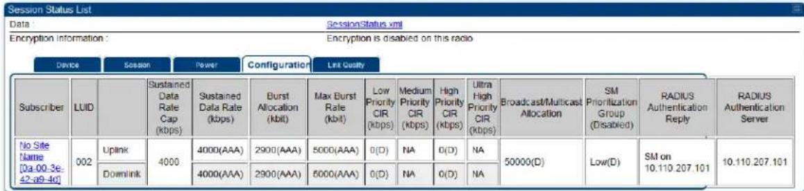 |
| Attribute | Meaning |
| Subscriber | See Table 228 on page 9-24. |
| LUID | See Table 228 on page 9-24. |
| Sustained Data Rate Cap (kbps) | This field specifies the maximum sustained data rate between SM/BHS and AP/BHM. If this field displays “Uncapped”, then there is no limit set for data rate. If this field displays 4000, then the maximum sustained data rate between SM/BHS and AP/BHM is limited to 4000 kbps. |
| Sustained Data Rate (kbps) - Uplink | This field displays the value that is currently in effect for the SM/BHS, with the source of that value in parentheses. This is the specified rate at which each SM/BHS registered to this AP/BHM is replenished with credits for transmission. The configuration source of the value is indicated in parentheses.See Maximum Information Rate (MIR) Parameters on page 7-232. |
| Sustained Data Rate (kbps) - Downlink | This field displays the value that is currently in effect for the SM/BHS, with the source of that value in parentheses. This is the specified the rate at which the AP/BHM should be replenished with credits (tokens) for transmission to each of the SMs/BHS’s in its sector. The configuration source of the value is indicated in parentheses.See Maximum Information Rate (MIR) Parameters on page 7-232. |
| Burst Allocation (kbit) - Uplink | This field displays the value that is currently in effect for the SM/BHS, with the source of that value in parentheses. This is the specified maximum amount of data that each SM/BHS is allowed to transmit before being recharged at the Sustained Uplink Data Rate with credits to transmit more. The configuration source of the value is indicated in parentheses.See Interaction of Burst Allocation and Sustained Data Rate Settings on page 7-234 |
| Burst Allocation (kbit) - Downlink | This field displays the value that is currently in effect for the SM/BHS, with the source of that value in parentheses. This is the specified the rate at which the AP/BHM should be replenished with credits (tokens) for transmission to each of the SMs/BHS's in its sector. The configuration source of the value is indicated in parentheses.See Interaction of Burst Allocation and Sustained Data Rate Settings on page 7-234 |
| Max Burst Rate (kbit) - Uplink | The data rate at which an SM/BHS is allowed to burst (until burst allocation limit is reached) before being recharged at the Sustained Uplink Data Rate with credits to transit more. When set to 0 (default), the burst rate is unlimited.See Interaction of Burst Allocation and Sustained Data Rate Settings on page 7-234 |
| Max Burst Rate (kbit) - Downlink | The data rate at which an SM/BHS is allowed to burst (until burst allocation limit is reached) before being recharged at the Sustained Downlink Data Rate with credits to transit more. When set to 0 (default), the burst rate is unlimited.See Interaction of Burst Allocation and Sustained Data Rate Settings on page 7-234 |
| Low Priority CIR | This field indicates the minimum rate at which low priority traffic is sent over the uplink and downlink (unless CIR is oversubscribed or RF link quality is degraded). |
| Medium Priority CIR | This field indicates the minimum rate at which medium priority traffic is sent over the uplink and downlink (unless CIR is oversubscribed or RF link quality is degraded). |
| High Priority CIR | This field indicates the minimum rate at which high priority traffic is sent over the uplink and downlink (unless CIR is oversubscribed or RF link quality is degraded). |
| Ultra High Priority CIR | This field indicates the minimum rate at which ultra high priority traffic is sent over the uplink and downlink (unless CIR is oversubscribed or RF link quality is degraded). |
| Broadcast/Multicast Allocation | This field displays the data rate at which Broadcast and Multicast traffic is sent via the radio link. |
| SM Prioritization Group | This field displays the priority level configured on the SM under SM Prioritization Group. |
| RADIUS Authentication Reply | This field displays whether RADIUS server is reachable or not. |
| RADIUS Authentication Server | This field displays the associated RADIUS Authentication Server for each SM where it was authenticated. This information is useful when there are multiple RADIUS servers (maximum three servers supported by Cambium). If one server is not reachable, other configured servers are tried in sequential order as a fall-back. In this scenario, the Session Status is useful to identify associate RADIUS Authentication Server for all connected SMs. |
Table 232 Session Status > Configuration CIR configuration denotations
| Attribute | Meaning |
| (SM) | QoS/VLAN parameters are derived from the SM's/BHS's settings |
| (APCAP) | QoS/VLAN parameters are derived from the AP's settings, including any keyed capping (for radios capped at 4 Mbps, 10 Mbps, or 20 Mbps) |
| (D) | QoS/VLAN parameters are retrieved from the device, due to failed retrieval from the AAA or WM server. |
| (AAA) | QoS/VLAN parameters are retrieved from the RADIUS server |
| (BAM) QoS/VLAN parameters are retrieved from a WM BAM server | |
Link Quality tab
The Link Quality tab provides information on the Subscriber's UID, Link quality, Downlink, Uplink, Beacon, ReReg, and the Uptime.
This data is refreshed based on the Link Quality Update Interval parameter configuration under the Sessions Status page.

The Link Quality tab displays the calculated Link Quality Indicator (LQI) for the configured interval (Link Quality Update Interval parameter).
Table 233 Link Quality tab attributes
| Subscriber | LUID | Link Quality Indicator | Downlink | Uplink | Re-Reg | Uptime | |||||||
| Quality Index | Actual Average Rate | Expected Rate | Beacon Quality Index | Beacon % | Quality Index | Actual Average Rate | Expected Rate | Quality Index | Count | ||||
| SM15 [0a-00-3e-b4-d2-c9] | 012 | 100 | 100% | 8X | 8X | 100% | 100% | 100% | 8X | 8X | 100% | 0 | 02:38:46 |
| SM1 11 [0a-00-3e-b4-24-1a] | 003 | 100 | 100% | 8X | 8X | 100% | 100% | 100% | 8X | 8X | 100% | 0 | 02:38:13 |
| SM2 12 [0a-00-3e-b4-24-08] | 008 | 100 | 100% | 8X | 8X | 100% | 100% | 100% | 8X | 8X | 100% | 0 | 02:38:13 |
| SM3 13 [0a-00-3e-b4-d2-e0] | 007 | 100 | 100% | 4X | 4X | 100% | 100% | 100% | 4X | 4X | 100% | 0 | 02:38:17 |
| SM4 21 [0a-00-3e-b4-d3-36] | 002 | 100 | 100% | 4X | 4X | 100% | 100% | 100% | 4X | 4X | 100% | 0 | 02:38:17 |
| SM5 24 [0a-00-3e-b4-d2-fe] | 005 | 100 | 100% | 8X | 8X | 100% | 100% | 100% | 6X | 6X | 100% | 0 | 02:38:15 |
| SM6 22 [0a-00-3e-b4-d2-fl] | 009 | 100 | 100% | 8X | 8X | 100% | 100% | 100% | 6X | 6X | 100% | 0 | 02:38:15 |
| SM7 23 [0a-00-3e-b4-c2-sc] | 004 | 100 | 100% | 8X | 8X | 100% | 100% | 100% | 6X | 6X | 100% | 0 | 02:38:17 |
| SM8 26 [0a-00-3e-b4-c2-65] | 006 | 100 | 100% | 8X | 8X | 100% | 100% | 100% | 8X | 8X | 100% | O | O2:38:15 |
| Attribute | Meaning |
| Subscriber | See Table 228 on page 9-24. |
| LUID | See Table 228 on page 9-24. |
| Link Quality Indicator | This field displays quality of the link. It is calculated based on receive power, modulation rate, re-registrations and beacon percentage. |
| Downlink - Quality Index | This field displays the downlink quality in percentage. It is calculated based on Downlink receiver power, modulation rate, and beacon percentage. |
| Downlink -Actual Average Rate | This field displays the average Downlink modulation rate. For 450m, this field specifies the SU-MIMO Modulation Rate. |
| Downlink -Expected Rate | This field displays the expected modulation rate based on receive power in Downlink. |
| Downlink - Beacon Quality Index | This field displays the beacon quality index. It is calculated based on beacon percentage. |
| Downlink - Beacon % | This field displays the received beacon percentage. |
| Uplink - Quality Index | This field displays the uplink quality in percentage. It is calculated based on Uplink receiver power and modulation rate. |
| Uplink -Actual Average Rate | This field displays the average Uplink modulation rate. |
| Uplink - Expected Rate | This field displays the expected modulation rate based on receive power in Uplink. |
| Re-Reg - Quality Index | This field displays the re-registration quality. It is calculated based on the re-registration count. |
| Re-Reg Count | This field displays the number of re-registrations. |
| Uptime | This field displays the uptime of the device. |
Viewing Remote Subscribers
This page allows to view the web pages of registered SMs or BHS over the RF link. To view the pages for a selected SM/BHS, click its link. The General Status page of the SM opens.
Figure 207 Remote Subscribers page of AP
![Remote Subscriber Modules 01. .72 SM 5.7 MIMO P11 - [0a-00-3e-a0-00-79] - LUID: 005 02. .76 SM 5.7 SISO P11 - [0a-00-3e-39-35-4f] - LUID: 006 03. .77 SM 5.7 SISO P11 - [0a-00-3e-39-35-91] - LUID: 007 04. .81 450i SM 4.9/5.9 MIMO - [0a-00-3e-bb-00-d7] - LUID: 010 05. .82 SM 450i 4.9/5.9 MIMO - [0a-00-3e-bb-01-03] - LUID: 002 06. .83 450i SM 4.9/5.9 MIMO - [0a-00-3e-bb-00-ae] - LUID: 004 07. .84 450i SM 4.9/5.9 MIMO - [0a-00-3e-a2-c3-d8] - LUID: 009 08. .86 SM 450 P11 5.4/5.7 MIMO - [0a-00-3e-a0-00-71] - LUID: 008 09. No Site Name - [0a-00-3e-a2-c2-79] - LUID: 003](/content/2026/05/943724/images/5caf7dd52bb53747498dcc6f24892f8af6998a436e4fb0ed81cbd562550b3cb8.jpg)
Interpreting messages in the Event Log
Each line in the Event Log of a module Home page begins with a time and date stamp. However, some of these lines wrap as a combined result of window width, browser preferences and line length. You may find this tab easiest to use if you expand the window till all lines are shown beginning with time and date stamp.
Time and Date Stamp
The time and date stamp reflect one of the following:
• GPS time and date directly or indirectly received from the CMM4.
• NTP time and date from a NTP server (CMM4 may serve as an NTP server)
- The running time and date that you have set in the Time & Date web page.

Note
In the Time & Date web page, if you have left any time field or date field unset and clicked the Set Time and Date button, then the time and date default to 00:00:00 UT : 01/01/00.
A reboot causes the preset time to pause or, in some cases, to run in reverse. Additionally, a power cycle resets the running time and date to the default 00:00:00 UT : 01/01/00. Thus, whenever either a reboot or a power cycle has occurred, must reset the time and date in the Time & Date web page of any module that is not set to receive sync.
Event Log Data Collection
The collection of event data continues through reboots and power cycles. When the buffer allowance for event log data is reached, the system adds new data into the log and discards an identical amount of the oldest data.
Each line that contains the expression WatchDog flags an event that was both:
• considered by the system software to have been an exception
- recorded in the preceding line.
Conversely, a Fatal Error () message flags an event that is recorded in the next line. Some exceptions and fatal errors may be significant and require either operator action or technical support.
Figure 208 Event log data
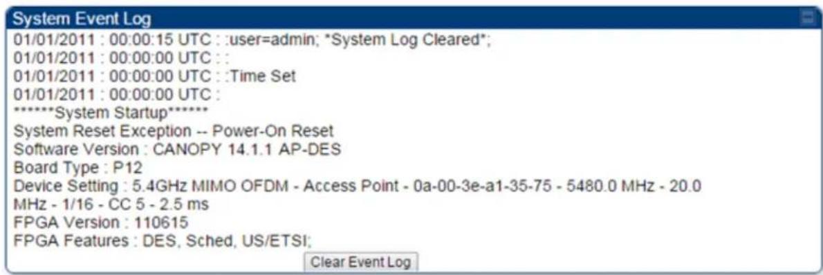
Messages that Flag Abnormal Events
The messages listed below flag abnormal events and, case by case, may signal the need for corrective action or technical support.
Table 234 Event Log messages for abnormal events
| Event Message | Meaning |
| Expected LUID = 6Actual LUID = 7 | Something is interfering with the control messaging of the module. Also ensure that you are using shielded cables to minimize interference. Consider trying different frequency options to eliminate or reduce interference. |
| FatalError() | The event recorded on the line immediately beneath this message triggered the Fatal Error (). |
| Loss of GPS Sync Pulse | Module has lost GPS sync signal. |
| Machine Check Exception | This is a symptom of a possible hardware failure. If this is a recurring message, begin the RMA process for the module. |
| RcvFrmNum = 0x00066dExpFrmNum = 0x000799 | Something is interfering with the control messaging of the module. Also ensure that you are using shielded cables to minimize interference. Consider trying different frequency options to eliminate or reduce interference. |
| System ResetException -- External Hard Reset | The unit lost power or was power cycled. |
| System ResetException -- External Hard Reset WatchDog | The event recorded on the preceding line triggered this WatchDog message. |
Messages that Flag Normal Events
The messages listed below record normal events and typically do not signal a need for any corrective action or technical support.
Table 235 Event Log messages for normal events
| Event Message | Meaning |
| Acquired GPS Sync Pulse. | Module has acquired GPS sync signal. |
| FPGA Features Type of encryption. | |
| FPGA Version FPGA (JBC) version in the module. | |
| GPS Date/Time Set Module is now on GPS time. | |
| Reboot from Webpage | Module was rebooted from management interface. |
| Software Boot Version | Boot version in the module. |
| Software Version | The software release and authentication method for the unit. |
| System Log Cleared | Event log was manually cleared. |
Viewing the Network Interface
In any module, the LAN1 Network Interface section of this tab displays the defined Internet Protocol scheme for the Ethernet interface to the module. In SM/BHS devices, this page also provides an RF Public Network Interface section, which displays the Internet Protocol scheme defined for network access through the master device (AP/BHM).
Figure 209 Network Interface tab of the AP
| LAN1 Network Interface | |
| Ethernet Interface : | 1000Base-TX Full Duplex |
| IP address : | 10.120.226.64 |
| Subnet Mask : | 255.255.254.0 |
| Gateway IP address : | 10.120.226.254 |
| Preferred DNS Server : | 10.120.12.31 |
| Alternate DNS Server : | 10.120.12.30 |
| DHCP status : | DHCP not enabled |
Figure 210 Network Interface tab of the SM
| LAN1 Network Interface | |
| Ethernet Interface : | 1000Base-TX Full Duplex |
| IP address : | 10.120.216.220 |
| Subnet Mask : | 255.255.255.0 |
| Gateway IP address : | 10.120.216.254 |
| Preferred DNS Server : | 0.0.0.0 |
| Alternate DNS Server : | 0.0.0.0 |
| DHCP status : | DHCP not enabled |
Viewing the Layer 2 Neighbors
In the Layer 2 Neighbors tab, a module reports any device from which it has received a message in Link Layer Discovery Protocol within the previous two minutes. Given the frequency of LLDP messaging, this means that the connected device will appear in this tab 30 seconds after it is booted and remain until two minutes after its shutdown.
Figure 211 Layer 2 Neighbors page

System statistics
This section describes how to use the system statistics pages to manage the performance of the PMP/PTP 450 Platform Family link.
Viewing the Scheduler statistics
The Statistics > Scheduler page is applicable for all modules (AP/SM/BHM/BHS) and the parameters are displayed as shown below:
Table 236 Scheduler tab attributes
| Radio Statistics | |
| Transmit Unicast Data Count : | 0 |
| Transmit Broadcast Data Count : | 393 |
| Transmit Multicast Data Count : | 0 |
| Receive Unicast Data Count : | 0 |
| Receive Broadcast Data Count : | 0 |
| Receive Multicast Data Count : | 0 |
| Transmit Control Count : | 0 |
| Receive Control Count : | 0 |
| In Sync Count : | 0 |
| Out of Sync Count : | 0 |
| Overrun Count : | 0 |
| Underrun Count : | 0 |
| Receive Corrupt Data Count : | 0 |
| Receive Corrupt Control Data Count : | 0 |
| Receive Bad Broadcast Control Count : | 0 |
| Rcv LT Start : | 0 |
| Rcv LT Start HS : | 0 |
| Rcv LT Result : | 0 |
| Xmt LT Result : | 0 |
| Frame Too Big : | 0 |
| Bad Acknowledgment : | 0 |
| Bad Fragment : | 0 |
| VC Clear Error Count : | 0 |
| Rx No Buffer Count : | 0 |
| Scheduler Error : | 0 |
Clear Statistics
| Attribute | Meaning |
| Transmit Unicast Data Count | Total amount of unicast packets transmitted from the radio |
| Transmit Broadcast Data Count | Total amount of broadcast packets transmitted from the radio |
| Transmit Multicast Data Count | Total amount of multicast packets transmitted by the radio |
| Receive Unicast Data Count | Total amount of unicast packets received by the radio |
| Receive Broadcast Data Count | Total amount of broadcast packets received by the radio |
| Receive Multicast Data Count | Total amount of multicast packets received by the radio |
| Transmit Control Count | Amount of radio control type messages transmitted (registration requests and grants, etc.) |
| Receive Control Count | Amount of radio control type messages received (registration requests and grants, etc.) |
| In Sync Count Number of times the radio has acquired sync. When GPS synchronization is used it is number of times GPS sync acquired. For the SM, it is the number of times the SM successfully obtained sync with an AP. | |
| Out of Sync Count | Number of times the radio lost same sync lock |
| Overrun Count | Number of times FPGA frame has overrun its TX Frame |
| Underrun Count | Number of times FPGAs TX Frame aborted prematurely |
| Receive Corrupt Data Count | Number of times a corrupt packet has been received at the FPGA. |
| Receive Corrupt Control Data Count | Number of times a corrupt control data packet has been received at the FPGA. |
| Receive Bad Broadcast Control Count | Number of times the radio has received an invalid control message via broadcast (SM only). |
| Rcv LT Start | Number of Link Test Start messages received. A remote radio has requested that this radio start a link test to it. |
| Rcv LT Start HS | Number of Link Test Start Handshake messages received. This radio requested that a remote radio start a link test and the remote radio has sent a handshake back acknowledging the start. |
| Rcv LT Result | This radio received Link Test results from the remote radio under test. When this radio initiates a link test, the remote radio will send its results to this radio for display. |
| Xmt LT Result | This radio transmitted its link test results to the remote radio under test. When the remote radio initiates a link test, this radio must send its results to the remote radio for display there. |
| Frame Too Big | This statistic indicates the number of packets received and processed by the radios which were greater than max packet size 1700 bytes. |
| Bad Acknowledgment | This statistic indicates the number of packets received as bad acknowledgment. It is for engineering use only. |
| Bad Fragment This statistic indicates number of fragments tagged internally as bad. It is for engineering use only. | |
| VC Clear Error Count | This statistic indicates number of times VC clear failed. |
| Rx No Buffer Count Currently unused | |
| Scheduler Error | This error is incremented when the scheduler cannot send or get scheduled to send a packet. It is also called as “VC Error”. |
Viewing list of Registration Failures statistics
SM Registration Failures page of AP
The SM Registration Failures tab identifies SMs that have recently attempted and failed to register to this AP. With its time stamps, these instances may suggest that a new or transient source of interference exists.
Table 237 SM Registration Failures page attributes - AP
| Registration Failures Statistics |
| Number of Registration Grant Failures : 1 |
| Most Recent Registration Failure List |
| MAC : 0a-00-3e-04-a7-26 AAA Session Retry 12/31/2010 : 19:23:30 CST : Status : 17 Flag : 0 |
| Attribute | Meaning |
| Status 17 Flag 0 | No response was received from the AAA server and hence SM is trying to send a session request again. |
BHS Registration Failures page of BHM
Table 238 BHS Registration Failures page attributes - BHM
| Registration Failures Statistics |
| Number of Registration Grant Failures : 1 |
| Most Recent Registration Failure List |
| MAC : 0a-00-3e-04-a7-26 AAA Session Retry 12/31/2010 : 19:23:30 CST : Status : 17 Flag : 0 |
| Attribute | Meaning |
| Status 17 Flag 0 | No response was received from the AAA server and hence BHS is trying to send a session request again. |
There is a list of flags from 0 to 20 as shown in Table 239 and the "Flags" can be ignored.
Table 239 Flags status
| Flag | Meaning | Flag | Meaning |
| 0 | Normal | 11 | AP Lite Limit Reached |
| 1 | Out of Range | 12 | Only Ver 9.5+ Allowed |
| 2 | No Luids | 13 | Temporary Data VC for AAA |
| 3 | BH ReRange | 14 | AAA Authentication Failure |
| 4 | Auth Fail | 15 | Registration Grant Reject |
| 5 | Encrypt Fail 16 Blank | ||
| 6 | Power Adjust | 17 | AAA Session Retry |
| 7 | No VCs | 18 | AAA Reauth Failure |
| 8 | Reserve VC Fail | 19 | RegReq at zero power |
| 9 | Activate VC Fail | 20 | RegReq no time ref |
| 10 | Hi VC Setup Fail | - | - |
Interpreting Bridging Table statistics
If NAT (network address translation) is not active on the SM/BHS, then the Bridging Table page provides the MAC address of all devices that are attached to registered SMs/BHS (identified by LUIDs).
The SM/BHS management MAC addresses are also added in bridge table upon SMs/BHS registration. These entries will be remove automatically from the table once SMs/BHS is de-registered. This alleviates the arp cache > bridge cache timeout problems.
The bridging table allows data to be sent to the correct module as follows:
- For the AP/BHM, the uplink is from RF to Ethernet. Thus, when a packet arrives in the RF interface to the AP/BHM, the AP/BHM reads the MAC address from the inbound packet and creates a bridging table entry of the source MAC address on the other end of the RF interface.
- For the SM/BHS, the uplink is from Ethernet to RF. Thus, when a packet arrives in the Ethernet interface to one of these modules, the module reads the MAC address from the inbound packet and creates a bridging table entry of the source MAC address on the other end of the Ethernet interface.
Figure 212 Bridging Table page
Statistics → Bridging Table
5.4GHz MIMO OFDM - Access Point - 0a-00-3e-bb-00-fb

The Bridging Table supports up to 4096 entries.
Interpreting Translation Table statistics
When Translation Bridging is enabled in the AP, each SM keeps a table mapping MAC addresses of devices attached to the AP to IP addresses, as otherwise the mapping of end-user MAC addresses to IP addresses is lost. (When Translation Bridging is enabled, an AP modifies all uplink traffic originating from registered SMs such that the source MAC address of every packet is changed to that of the SM which bridged the packet in the uplink direction.)
Figure 213 Translation Table page of SM
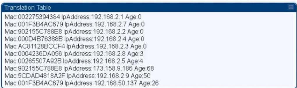
Interpreting Ethernet statistics
The Statistics > Ethernet page reports TCP throughput and error information for the Ethernet connection of the module. This page is applicable for all modules (AP/SM/BHM/BHS).
The Ethernet page displays the following fields.
Table 240 Ethernet tab attributes
| Ethernet Control Block Statistics | |
| Ethernet Link Detected: | 1 |
| Ethernet Link Lost: | 0 |
| Undersized Toss Count: | 0 |
| inoctets Count: | 139159 |
| inucastpkts Count: | 420 |
| Innucastpkts Count: | 86 |
| indiscards Count: | 0 |
| Inerrors Count: | 0 |
| inunknownprotos Count: | 0 |
| outoctets Count: | 56864 |
| outucastpktsCount: | 184 |
| outnucastpkts Count: | 3 |
| outdiscards Count: | 0 |
| outerrors Count: | 1 |
| RxBabErr: | 0 |
| TxHbErr: | 0 |
| EthBusErr: | 0 |
| CRCError: | 0 |
| RcvFifoNoBuf: | 0 |
| RxOverrun: | 0 |
| LateCollision: | 0 |
| RetransLimitExp: | 0 |
| TxUnderrun: | 0 |
| CarSenseLost: | 0 |
| No Carrier: | 1 |
Attribute
Meaning
| Ethernet Link Detected | 1 indicates that an Ethernet link is established to the radio, 0 indicates that no Ethernet link is established | |
| Ethernet Link Lost | This field indicates a count of how many times the Ethernet link was lost. | |
| Undersized Toss Count | This field indicates the number of packets that were too small to process and hence discarded. | |
| inoctets Count | This field displays how many octets were received on the interface, including those that deliver framing information. | |
| inucastpkts Count | This field displays how many inbound subnetwork-unicast packets were delivered to a higher-layer protocol. | |
| Innucastpkts Count | This field displays how many inbound non-unicast (subnetwork-broadcast or subnetwork-multicast) packets were delivered to a higher-layer protocol. | |
| indiscards Count | This field displays how many inbound packets were discarded without errors that would have prevented their delivery to a higher-layer protocol. (Some of these packets may have been discarded to increase buffer space.) | |
| inerrors Count | This field displays how many inbound packets contained errors that prevented their delivery to a higher-layer protocol. | |
| inunknownprotos Count | This field displays how many inbound packets were discarded because of an unknown or unsupported protocol. | |
| outoctets Count | This field displays how many octets were transmitted out of the interface, including those that deliver framing information. | |
| outucastpkts Count | This field displays how many packets for which the higher-level protocols requested transmission to a subnetwork-unicast address. The number includes those that were discarded or not sent. | |
| outnucastpkts Count | This field displays how many packets for which the higher-level protocols requested transmission to a non-unicast (subnetwork-broadcast or subnetwork-multicast) address. The number includes those that were discarded or not sent. | |
| outdiscards Count | This field displays how many outbound packets were discarded without errors that would have prevented their transmission. (Some of these packets may have been discarded to increase buffer space.) | |
| outerrors Count | This field displays how many outbound packets contained errors that prevented their transmission. | |
| RxBabErr | This field displays how many receiver babble errors occurred. | |
| TxHbErr | This field displays how many transmit heartbeat errors have occurred. | |
| EthBusErr | This field displays how many Ethernet bus errors occurred on the Ethernet controller. | |
| CRCError | This field displays how many CRC errors occurred on the Ethernet controller. | |
| RcvFifoNoBuf | This field displays the number of times no FIFO buffer space was able to be allocated. | |
 | Note:PMP 450 AP running in Gigabit Ethernet Mode displays error “RcfFifoNoBuf” which indicates packet loss.For 450 AP platforms, if ethernet auto-negotiation is set to Gigabit, then it is a known limitation that “RcfFifoNoBuf” error will be seen. This issue is not seen if autonegotation is set to 100Mbps or lower, and the issue is not seen on 450i or 450m AP's. | |
| RxOverrun | This field displays how many receiver overrun errors occurred on the Ethernet controller. | |
| Late Collision | This field displays how many late collisions occurred on the Ethernet controller. A normal collision occurs during the first 512 bits of the frame transmission. A collision that occurs after the first 512 bits is considered a late collision. | |
 | CautionA late collision is a serious network problem because the frame being transmitted is discarded. A late collision is most commonly caused by a mismatch between duplex configurations at the ends of a link segment. | |
| RetransLimitExp | This field displays how many times the retransmit limit has expired. | |
| TxUnderrun | This field displays how many transmission-underrun errors occurred on the Ethernet controller. | |
| CarSenseLost | This field displays how many carrier sense lost errors occurred on the Ethernet controller. | |
| No Carrier | This field displays how many no carrier errors occurred on the Ethernet controller. | |
Interpreting RF Control Block statistics
The Statistics > Radio page is applicable for all module (AP/SM/BHM/BHS). The Radio page of the Statistics page displays the following fields.
Table 241 Radio (Statistics) page attributes - RF Control Block
| RF Control Block Statistics | |
| inoctets Count : | 653532396 |
| inucastpkts Count : | 423096 |
| Innucastpkts Count : | 35848043 |
| indiscards Count : | 0 |
| inerrors Count : | 0 |
| inunknownprotos Count : | 0 |
| outoctets Count : | 138721214 |
| outucastpktsCount : | 401826 |
| outnucastpkts Count : | 13855 |
| outdiscards Count : | 120 |
| outerrors Count : | 0 |
| Attribute | Meaning |
| inoctets Count This field displays how many octets were received on the interface, including those that deliver framing information. | |
| inucastpkts Count | This field displays how many inbound subnetwork-unicast packets were delivered to a higher-layer protocol. |
| Innucastpkts Count | This field displays how many inbound non-unicast (subnetwork-broadcast or subnetwork-multicast) packets were delivered to a higher-layer protocol. |
| indiscards Count | This field displays how many inbound packets were discarded without errors that would have prevented their delivery to a higher-layer protocol. This stat is pegged whenever corrupt data is received by software or whenever the RF Software Bridge queue is full.Corrupt data is a very unusual event because all packets are CRC checked by hardware before being passed into software.The likely case for indiscards is if the RF bridge queue is full. If this is the case the radio is most likely PPS limited due to excessive small packet traffic or a problem at the Ethernet interface. If there is a problem at the Ethernet interface there is likely to be discards at the Ethernet as well. |
| inerrors Count | This field displays how many inbound packets contained errors that prevented their delivery to a higher-layer protocol. |
| inunknownprotos Count | This field displays how many inbound packets were discarded because of an unknown or unsupported protocol. |
| outoctets Count | This field displays how many octets were transmitted out of the interface, including those that deliver framing information. |
| outucastpkts Count | This field displays how many packets for which the higher-level protocols requested transmission to a subnetwork-unicast address. The number includes those that were discarded or not sent. |
| outnucastpkts Count | This field displays how many packets for which the higher-level protocols requested transmission to a non-unicast (subnetwork-broadcast or subnetwork-multicast) address. The number includes those that were discarded or not sent. |
| outdiscards Count | This field displays how many outbound packets were discarded without errors that would have prevented their transmission. (Some of these packets may have been discarded to increase buffer space.) |
| outerrors Count | This field displays how many outbound packets contained errors that prevented their transmission. |
Interpreting Sounding statistics for AP
In the 450m AP GUI, sounding statistics can be found under Statistics > Sounding Statistics.
Table 242 Sounding Statistics - 450m AP page attributes
| Sounding Statistics | |||||||
| Subscriber | LUID | Spatial Frequency | Azimuth (Degrees) | Downlink | Uplink | ||
| Sounding State | MU-MIMO Rate | Sounding State | MU-MIMO Rate | ||||
| SM4 21 [0a-00-3e-b4-d3-36] | 002 | 879 | -59.7, -9.1, 41.6 | TRACKING | 4X/2X MIMO-A | TRACKING | 4X/4X MIMO-B |
| SM1 11 [0a-00-3e-b4-24-1a] | 003 | 2 | -50.6, 0.1, 50.7 | TRACKING | 8X/8X MIMO-B | TRACKING | 8X/1X MIMO-A |
| SM7 23 [0a-00-3e-b4-c2-5c] | 004 | 879 | -59.7, -9.1, 41.6 | TRACKING | 8X/8X MIMO-B | TRACKING | 8X/6X MIMO-B |
| SM5 24 [0a-00-3e-b4-d2-fe] | 005 | 879 | -59.7, -9.1, 41.6 | TRACKING | 8X/8X MIMO-B | TRACKING | 8X/6X MIMO-B |
| SM8 26 [0a-00-3e-b4-c2-65] | 006 | 879 | -59.7, -9.1, 41.6 | TRACKING | 8X/8X MIMO-B | TRACKING | 8X/8X MIMO-B |
| SM3 13 [0a-00-3e-b4-d2-e0] | 007 | 2 | -50.6, 0.1, 50.7 | TRACKING | 4X/4X MIMO-B | TRACKING | 4X/4X MIMO-B |
| SM2 12 [0a-00-3e-b4-24-08] | 008 | 2 | -50.6, 0.1, 50.7 | TRACKING | 8X/8X MIMO-B | TRACKING | 8X/8X MIMO-B |
| SM6 22 [0a-00-3e-b4-d2-ff] | 009 | 879 | -59.7, -9.1, 41.6 | TRACKING | 8X/8X MIMO-B | TRACKING | 8X/6X MIMO-B |
| SM15 [0a-00-3e-b4-d2-c9] | 012 | 2 | -50.6, 0.1, 50.7 | TRACKING | 8X/8X MIMO-B | TRACKING | 8X/8X MIMO-B |
| Attribute | Meaning | |
| Subscriber | This field displays the MAC address and Site Name of the SM/BHS. As each SM or BHS registers to the AP/BHM. | |
| LUID | This field displays the LUID (logical unit ID) of the SM/BHS. As each SM or BHS registers to the AP/BHM, the system assigns an LUID of 2 or a higher unique number to the SM/BHS. If a SM/BHS loses registration with the AP/BHS and then regains registration, the SM/BHS will retain the same LUID. | |
| Spatial Frequency | This field displays the spatial frequency value of the LUID or SM. Values 0 to 1023 are valid and value 2048 is considered as invalid. | |
| Azimuth | This field displays the Azimuth range in degrees corresponding to the spatial frequencies of the bin. The zero-degree azimuth is boresight. | |
 | Note:Some SF ranges correspond to multiple azimuth ranges.This is because for some spatial frequencies the AP generates beams in multiple azimuth directions. The SM can be physically located in any of the azimuth ranges. | |
| Downlink - Sounding State | Different types of Sounding states are:UNKNOWN: SM has recently registered to the AP but not registered with the channel manager yet.NEW: SM has been registered with the channel manager and will soon transition to ASSESSING. | |
| ASSESSING: AP will instruct SM to take the channel measurements. Channel estimates and spatial frequencies will be calculated.TRACKING: Valid measurements resulted in good channel estimates and spatial frequency. This SM can now be used for MU-MIMO.INVALID: Inconsistent measurements resulting in no channel estimate or spatial frequency. This SM cannot be used for MU-MIMO and it will ultimately be re-assessed.NOT ELIGIBLE: Due to poor RF link conditions, the RF link as rate adapted down to SU-MIMO transmissions. | ||
| Downlink - MU-MIMO Rate | This field indicates the modulation rate used for symbols where this particular LUID is MU-MIMO scheduled by grouping it in the same slot with other LUIDs. | |
| Uplink - Sounding State | This field indicates the status of uplink sounding. | |
| Uplink - MU-MIMO Rate | This field indicates the modulation rate used for symbols where the MUMIMO groupable data channels are MU-MIMO scheduled by grouping it in the same slot with other MU-MIMO groupable data channels from other SM's. | |
Interpreting VLAN statistics
The Statistics > VLAN page provides a list of the most recent packets that were filtered because of VLAN membership violations. It is applicable for all modules (AP/SM/BHM/BHS).
Table 243 VLAN page attributes
| VLAN Statistics Configuration | |
| VLAN Statistics Configuration : | 1 (Range : 1 — 4094 or 0 for Priority-tagged) |
| VLAN Statistics | |
| VID : | 1 |
| VID Stats Frames Received : 1823 | |
| Bytes Received : 586624 | |
| Frames Transmitted : 1640 | |
| Bytes Transmitted : 585735 | |
| Most Recent Filtered Frames | |
| No Ingress Filtered Frames | |
| Ingress : Total Frames Filtered : 0 Total Bytes Filtered : 0 | |
| Egress : Total Frames Filtered : 0 Total Bytes Filtered : 0 | |
| Attribute | Meaning |
| Unknown | This must not occur. Contact Technical Support. |
| Only Tagged | The packet was filtered because the configuration is set to accept only packets that have an 802.1Q header and this packet did not. |
| Ingress | When the packet entered through the wired Ethernet interface, the packet was filtered because it indicated an incorrect VLAN membership. |
| Local Ingress | When the packet was received from the local TCP/IP stack, the packet was filtered because it indicated an incorrect VLAN membership. This must not occur. Contact Technical Support. |
| Egress | When the packet attempted to leave through the wired Ethernet interface, the packet was filtered because it indicated an incorrect VLAN membership. |
| Local Egress | When the packet attempted to reach the local TCP/IP stack, the packet was filtered because it indicated an incorrect VLAN membership. |
Interpreting Data Channels statistics
The Statistics > Data Channels page displays information about data channels used in data communications. This page is applicable for all modules (AP/SM/BHM/BHS).
The Data VC tab displays the fields as explained in Table 244.
Table 244 Data Channel page attributes
| Subscriber | LUID | Channel Priority | Inbound Statistics | Outbound Statistics | Queue Overflow | High Priority Queue | ||||||||
| octets | ucast pkts | nucast pkts | discards | errors | octets | ucast pkts | nucast pkts | discards | errors | |||||
| SM4 21 | 002 | Low | 88471406 | 8 | 51742 | 0 | 0 | 78002604 | 681 | 45566 | 0 | 0 | 0 | 160 |
| SM4 21 | 002 | Medium | 107730 | 0 | 63 | 0 | 0 | 107730 | 0 | 63 | 0 | 0 | 0 | 0 |
| SM4 21 | 002 | High | 107730 | 0 | 63 | 0 | 0 | 107730 | 0 | 63 | 0 | 0 | 0 | 0 |
| SM4 21 | 002 | Ultra High | 1038574 | 6678 | 100 | 0 | 0 | 152829 | 158 | 311 | 0 | 0 | 0 | 406 |
| SM1 11 | 003 | Low | 1959 | 4 | 2 | 0 | 0 | 99422 | 777 | 0 | 0 | 0 | 0 | 241 |
| SM1 11 | 003 | Medium | 0 | 0 | 0 | 0 | 0 | 0 | 0 | 0 | 0 | 0 | 0 | 0 |
| SM1 11 | 003 | High | 0 | 0 | 0 | 0 | 0 | 0 | 0 | 0 | 0 | 0 | 0 | 0 |
| SM1 11 | 003 | Ultra High | 648533 | 3960 | 36 | 0 | 0 | 41899 | 158 | 198 | 0 | 0 | 0 | 356 |
| SM7 23 | 004 | Low | 10898303 | 5 | 6375 | 0 | 0 | 98431 | 811 | 1 | 0 | 0 | 0 | 292 |
| SM7 23 | 004 | Medium | 0 | 0 | 0 | 0 | 0 | 0 | 0 | 0 | 0 | 0 | 0 | 0 |
| SM7 23 | 004 | High | 0 | 0 | 0 | 0 | 0 | 0 | 0 | 0 | 0 | 0 | 0 | 0 |
| SM7 23 | 004 | Ultra High | 636897 | 4008 | 37 | 0 | 0 | 45099 | 158 | 248 | 0 | 0 | 0 | 406 |
| SM5 24 | 005 | Low | 10893173 | 5 | 6372 | 0 | 0 | 98204 | 764 | 1 | 0 | 0 | 0 | 234 |
| SM5 24 | 005 | Medium | 0 | 0 | 0 | 0 | 0 | 0 | 0 | 0 | 0 | 0 | 0 | 0 |
| SM5 24 | 005 | High | 0 | 0 | 0 | 0 | 0 | 0 | 0 | 0 | 0 | 0 | 0 | 0 |
| SM5 24 | 005 | Ultra High | 671486 | 4201 | 37 | 0 | 0 | 45099 | 158 | 248 | 0 | 0 | 0 | 406 |
| SM8 26 | 006 | Low | 14487593 | 5 | 8474 | 0 | 0 | 95888 | 742 | 1 | 0 | 0 | 0 | 224 |
| SM8 26 | 006 | Medium | 0 | 0 | 0 | 0 | 0 | 0 | 0 | 0 | 0 | 0 | 0 | 0 |
| SM8 26 | 006 | High | 0 | 0 | 0 | 0 | 0 | 0 | 0 | 0 | 0 | 0 | 0 | 0 |
| SM8 26 | 006 | Ultra High | 751670 | 4625 | 36 | 0 | 0 | 45057 | 157 | 248 | 0 | 0 | 0 | 405 |
| SM3 13 | 007 | Low | 12993053 | 5 | 7600 | 0 | 0 | 89789 | 670 | 1 | 0 | 0 | 0 | 154 |
| SM3 13 | 007 | Medium | 0 | 0 | 0 | 0 | 0 | 0 | 0 | 0 | 0 | 0 | 0 | 0 |
| SM3 13 | 007 | High | 0 | 0 | 0 | 0 | 0 | 0 | 0 | 0 | 0 | 0 | 0 | 0 |
| SM3 13 | 007 | Ultra High | 636026 | 3966 | 36 | 0 | 0 | 45099 | 158 | 248 | 0 | 0 | 0 | 406 |
| SM2 12 | 008 | Low | 21802973 | 5 | 12752 | 0 | 0 | 94194 | 739 | 1 | 0 | 0 | 0 | 220 |
| SM2 12 | 008 | Medium | 0 | 0 | 0 | 0 | 0 | 0 | 0 | 0 | 0 | 0 | 0 | 0 |
| SM2 12 | 008 | High | 0 | 0 | 0 | 0 | 0 | 0 | 0 | 0 | 0 | 0 | 0 | 0 |
| SM2 12 | 008 | Ultra High | 637607 | 3981 | 36 | 0 | 0 | 45099 | 158 | 248 | 0 | 0 | 0 | 406 |
| SM6 22 | 009 | Low | 10908563 | 5 | 6381 | 0 | 0 | 100175 | 801 | 1 | 0 | 0 | 0 | 275 |
| SM6 22 | 009 | Medium | 0 | 0 | 0 | 0 | 0 | 0 | 0 | 0 | 0 | 0 | 0 | 0 |
| SM6 22 | 009 | High | 0 | 0 | 0 | 0 | 0 | 0 | 0 | 0 | 0 | 0 | 0 | 0 |
| SM6 22 | 009 | Ultra High | 696681 | 4521 | 36 | 0 | 0 | 45099 | 158 | 248 | 0 | 0 | 0 | 406 |
| SM15 | 012 | Low | 22323135 | 3924 | 12741 | 0 | 0 | 142215 | 946 | 250 | 0 | 0 | 0 | 675 |
| Multicast | 252 | NA | NA | NA | NA | NA | NA | 86504 | 0 | 415 | 0 | 0 | NA | NA |
| Broadcast | 255 | NA | NA | NA | NA | NA | NA | 1006314 | 18 | 15912 | 0 | 0 | NA | NA |
| Subscriber | LUID | Receive Fragments Modulation | Retransmitted Fragments | |||
| QPSK | 16-QAM | 64-QAM | 256-QAM | |||
| No Site Name | 002 | 44171 256 | 43626 221 | 43594 173 | 231 99 | 0 |
| Attribute | Meaning |
| Subscriber | This field displays the MAC address and Site Name of the SM/BHS. |
| LUID | This field displays the LUID (logical unit ID) of the SM/BHS. As each SM or BHS registers to the AP/BHM, the system assigns an LUID of 2 or a higher unique number to the SM/BHS. If a SM/BHS loses registration with the AP/BHS and then regains registration, the SM/BHS will retain the same LUID. |

Note
Both the LUID and the MAC are hot links to open the interface to the SM/BHS. In some instances, depending on network activity and network design, this route to the interface yields a blank web page. If this occurs, refresh your browser view.
| Channel Priority | This field displays the channel priority for the virtual channel. The values supported are Low, Medium, High, and Ultra High. |
| Inbound Statistics, octets | This field displays how many octets were received on the interface, including those that deliver framing information. |
| Inbound Statistics, ucastpkts | This field displays how many inbound subnetwork-unicast packets were delivered to a higher-layer protocol. |
| Inbound Statistics, nucastpkts | This field displays how many inbound non-unicast (subnetwork-broadcast or subnetwork-multicast) packets were delivered to a higher-layer protocol. |
| Inbound Statistics, discards | This field displays how many inbound packets were discarded without errors that would have prevented their delivery to a higher-layer protocol. Inbound discard statistics are incremented similar to the indiscards stat on the RF control block stats page. The sum of all data VC indiscards must be close to the RF control block in discards. If indiscards are evenly distributed across SMs, then the radio is PPS limited due to either excessive small packet transmissions, or a problem at the Ethernet link. If indiscards are contained to one or a few SMs, then there is likely a problem at or underneath the SM which is incrementing the count. |
| Outbound Statistics, octets | This field displays how many octets were transmitted out of the interface, including those that deliver framing information. |
| Outbound Statistics, ucastpkts | This field displays how many packets for which the higher-level protocols requested transmission to a subnetwork-unicast address. The number includes those that were discarded or not sent. |
| Outbound Statistics, nucastpkts | This field displays how many packets for which the higher-level protocols requested transmission to a non-unicast (subnetwork-broadcast or subnetwork-multicast) address. The number includes those that were discarded or not sent. |
| Outbound Statistics, discards | This field displays how many outbound packets were discarded without errors that would have prevented their transmission. Outbound discard statistics are incremented if a VC is not active when a packet is ready to send. This is a rare condition. |
| Outbound Statistics, errors | This field displays how many outbound packets contained errors that prevented their transmission. |
| Queue Overflow | This is a count of packets that were discarded because the queue for the VC was already full. If Queue Overflows are being seen across most or all SMs, then there is either an interferer local to the AP or the APs RF link is at capacity. If Queue Overflows are being seen at one or only a few SMs, then it is likely that there is a problem with those specific links whether it is insufficient signal strength, interferer, or a problem with the actual SM hardware. |
| High Priority Queue | This is a count of packets that were received on high priority queue. |
| Fragments Modulation - Receive Fragments Modulation | |
| QPSK | This field displays how many inbound fragments were received via the QPSK modulation scheme. |
| 16-QAM | This field displays how many inbound fragments were received via the 16-QAM modulation scheme. |
| 64-QAM | This field displays how many inbound fragments were received via the 64-QAM modulation scheme. |
| 256-QAM | This field displays how many inbound fragments were received via the 256-QAM modulation scheme. |
| Retransmitted Fragments | This field displays how many outbound fragments were retransmitted. |
Interpreting MIR/Burst statistics
The Statistics > MIR/Burst page displays information about MIR/Burst. This page is applicable for all modules (AP/SM).
The MIR/Burst tab displays the fields as explained in Table 245 and Table 246.
Table 245 MIR/Burst page attributes for AP
| MIR / Burst Statistics | ||||||||||
| Note: Uplink values are configuration values only. Live uplink values will be shown on the SM. | ||||||||||
| Subscriber | Current Downlink Bucket Size | Downlink MIR | Downlink MIR Per 500ms Interval | Downlink Max Bucket Size | Current Max Burst Bucket Size | Downlink Max Burst MIR | Downlink Max Burst MIR Per 500ms Interval | Uplink MIR | Uplink Max Bucket Size | Uplink Max Burst MIR |
| No Site Name - LUID_002 | 2500000000 | 30000000 | 15000000 | 2500000000 | 0 | 0 (Not Limited) | 0 (Not Limited) | 30000000 | 2500000000 | 0 (Not Limited) |
| Attribute | Meaning |
| Subscriber | This field displays the LUID (logical unit ID), MAC address and Site Name of the SM/BHS. As each SM or BHS registers to the AP/BHM, the system assigns an LUID of 2 or a higher unique number to the SM/BHS. As of release 15.2, if an SM/BHS loses registration with the AP/BHM and then regains registration, the SM/BHS retains the same LUID. |
| Current Downlink Bucket Size | This field displays the number of bits in the bucket to be potentially consumed at above-MIR rates, up to Max Burst MIR rate. |
| Downlink MIR | This field displays the active configured MIR rate per second. This is the rate that the bucket is filled with bits. |
| Downlink MIR Per 500ms Interval | This field displays the rate that the bucket is filled with bits at every 500 ms interval. |
| Downlink Max Bucket Size | This field displays the configured maximum bucket size, which is the maximum number of bits that can be in the bucket. The bucket fills at MIR rate and can hold this number of bits, which is a configuration value. |
| Current Max Burst Bucket Size | If Max Burst is enabled, there is a secondary “bucket” that controls the maximum rate of bit consumption. If Max Burst is not enabled (which means not limited), this will be 0 as the bucket is not used. |
| Downlink Max Burst MIR | This field displays the configured value of the Max Burst rate. This is the maximum rate at which bits can be consumed above MIR. Once excess (>MIR) bits have been consumed, the link will be throttled to MIR. |
| Downlink Max Burst MIR Per 500ms Interval | This field displays the configured value of the Max Burst rate at every 500 ms interval. |
| Uplink MIR | This field displays the active configured MIR rate per second in the SM. |
| Uplink Max Bucket Size | This field displays the configured maximum bucket size of the SM, which is the maximum number of bits that can be in the bucket. The bucket fills at MIR rate and can hold this number of bits, which is a configuration value. |
| Uplink Max Burst MIR | This field displays the configured value of the MaxBurst rate of the SM. This is the maximum rate at which bits can be consumed above MIR. Once excess (>MIR) bits have been consumed, the link will be throttled to MIR. |
Table 246 MIR/Burst page attributes for SM
| Current Uplink Bucket Size | Uplink MIR | Uplink MIR Per 100ms Interval | Uplink Max Bucket Size | Current Max Burst Bucket Size | Uplink Max Burst MIR | Uplink Max Burst MIR Per 100ms Interval | Uplink Broadcast Credit | Uplink Broadcast MIR | Uplink Broadcast MIR Type | Downlink MIR | Downlink Max Bucket Size | Downlink Max Burst MIR |
| 2500000000 | 155000000 | 15500000 | 2500000000 | 0 | 0 (Not Limited) | 0 (Not Limited) | 0 | 0 | kbps | 155000000 | 2500000000 | 0 (Not Limited) |
Attribute
Meaning
| Current Uplink Bucket Size | This field displays the number of bits in the bucket to be potentially consumed at above-MIR rates, up to Max Burst MIR rate. |
| Uplink MIR | This field displays the active MIR rate per second. This is the rate that the bucket is filled with bits. |
| Uplink MIR Per 100ms Interval | This field displays the rate that the bucket is filled with bits at every 100 ms interval. |
| Uplink Max Bucket Size | This field displays the maximum bucket size, which is the maximum number of bits that can be in the bucket. The bucket fills at MIR rate and can hold this number of bits, which is a configuration value. |
| Current Max Burst Bucket Size | If Max Burst is enabled, there is a secondary “bucket” that controls the maximum rate of bit consumption. If Max Burst is not enabled (which means not limited), this will be 0 as the bucket is not used. |
| Uplink Max Burst MIR | This field displays the configured value of the Max Burst rate. This is the maximum rate at which bits can be consumed above MIR. Once excess (>MIR) bits have been consumed, the link will be throttled to MIR. |
| Uplink Max Burst MIR per 100ms Interval | This field displays the configured value of the Max Burst rate at every 100 ms interval. |
| Uplink Broadcast Credit | This field displays the broadcast credit. |
| Uplink Broadcast MIR | This field displays the broadcast MIR rate per second. |
| Uplink Broadcast MIR Type | This field displays the type of the broadcast MIR. |
| Downlink MIR | This field displays the active configured MIR rate per second. This is the rate that the bucket is filled with bits. |
| Downlink Max Bucket Size | This field displays the configured maximum bucket size, which is the maximum number of bits that can be in the bucket. The bucket fills at MIR rate and can hold this number of bits, which is a configuration value. |
| Downlink Max Burst MIR | This field displays the configured value of the Max Burst rate. This is the maximum rate at which bits can be consumed above MIR. Once excess (>MIR) bits have been consumed, the link will be throttled to MIR. |
Interpreting Throughput statistics
The 450 Platform Family has a Statistics > Throughput page which shows historical information about sector or backhaul throughput and packet discards. This page is applicable for AP and BHM modules. This information can be useful to identify an overloaded sector or heavy bandwidth users. This page also shows the user throughput in terms of data rate (kbps) and packet rate (packets per second, or PPS), as well as the average packet size during the sample period.
Operators may set the AP/BHM to send an SNMP trap when it detects an RF overload condition based on a configurable threshold.
The following configuration parameters are available on the Throughput tab GUI pane and a radio reboot is not required when configuring these parameters:
Table 247 RF overload Configuration attributes - AP/BHM
| RF Overload Configuration | |
| Throughput Monitoring : | ○ Enabled○ Disabled |
| SNMP Trap on RF Overload : | ○ Enabled○ Disabled |
| Downlink RF Overload Threshold : | 1 % (Range : 1—100 %) |
| Downlink RF Link Status : | RF Link within Capacity |
| Time Period Length : | 1 Hour |
| Time Period Ending : | |
| Attribute | Meaning |
| Throughput Monitoring | This enables or disables the monitoring of sector throughput and packet discards. This parameter is disabled by default. |
| SNMP Trap on RF Overload | This enables or disables the sending of an SNMP trap when an AP/BHM overload condition is reached (based on Downlink RF Overload Threshold). |
| Downlink RF Overload Threshold | This parameter determines the overload threshold in percent of packets discarded that triggers the generation of an SNMP trap. |
| Downlink RF Link Status | This field displays the status of the capacity of the RF link. |
| Time Period Length Time Period Ending | These two configuration parameters determine what set of collection samples to show on the GUI display. The Time Period Length can be set from one to three hours. Time Period Ending allows the operator to set the end time for the set of collection samples to display. |
Following configuration settings are three tables that display the statistics that are collected.
Board Performance statistics
This table contains a row that corresponds to each 1 minute statistics collection interval. Each row contains the following data aggregated for the entire AP/BHM:
- Ethernet Throughput - Statistics collected at the Ethernet port:
○ kbps in – average throughput over the collection interval in Kbps into the AP/BHM on the Ethernet Interface
○ kbps out – average throughput over the collection interval in Kbps out of the AP/BHM on the Ethernet Interface
o PPS in – average packets per second over the collection interval into the AP/BHM on the Ethernet Interface
o PPS out – average packets per second over the collection interval out of the AP/BHM on the Ethernet Interface
• RF Throughput - Statistics collected at the RF Interface:
○ kbps in – average throughput over the collection interval in Kbps into the AP/BHM on the RF Interface
○ kbps out – average throughput over the collection interval in Kbps out of the AP/BHM on the RF Interface
- PPS in – average packets per second over the collection interval into the AP/BHM on the RF Interface
- PPS out – average packets per second over the collection interval out of the AP/BHM on the RF Interface
- Aggregate Through Board - Sum of bidirectional data transferred through (not originating or terminating at) the AP/BHM:
- kbps – average bidirectional throughput over the collection interval in Kbps
- PPS – average bidirectional packets per second over the collection interval
- Ave Pkt Size – Average Packet size over the collection interval of bidirectional data transferred
Board Throughput statistics
This table contains a row that corresponds to each one minute statistics collection interval. This table may be used to determine if there are problems with any of the interfaces. For example, if the Ethernet in packets is much higher than the RF out packets it could indicate a denial of service (DoS) attack on the AP/BHM. Each row contains the following data aggregated for the entire AP/BHM:
- Ethernet Statistics - Statistics collected at the Ethernet port:
- inOctets – Number of octets (bytes) received by the AP/BHM at the Ethernet Interface over the collection interval
outOctets – Number of octets (bytes) sent by the AP/BHM at the Ethernet Interface over the collection interval - inPkts – Number of packets received by the AP/BHM at the Ethernet Interface over the collection interval
outPkts – Number of packets sent by the AP/BHM at the Ethernet Interface over the collection interval
- Discards (in/out) – Number of packets that had to be discarded by the AP/BHM at the respective Ethernet Interface Queue
• RF Statistics - Statistics collected at the RF Interface:
- inOctets – Number of octets (bytes) received by the AP/BHM at the RF Interface over the collection interval
outOctets – Number of octets (bytes) sent by the AP/BHM at the RF Interface over the collection interval
- inPkts – Number of packets received by the AP/BHM at the RF Interface over the collection interval
- outPkts – Number of packets sent by the AP/BHM at the RF Interface over the collection interval
- Discards (in/out) – Number of packets that had to be discarded by the AP/BHM at the respective RF Interface Queue during the collection interval
- Discards % (in/out) – Percent of the total packets received / transmitted that had to be discarded during the collection interval
LUID RF Throughput statistics
This table contains a row that corresponds to each active LUID served by the AP/BHM. Note that an LUID may be assigned 1 or 2 VCs. If the LUID is assigned 2 VCs, then the data in the table is the sum of the activity for both VCs. This table may be used to determine which LUIDs are experiencing overload so that corrective action can be taken (i.e. fixing a poor RF link or moving a heavily loaded link to a less congested AP/BHM). Each row contains counters and statistics related to the RF Interface that are updated once per minute:
• Inbound Statistics - Statistics collected at the RF Interface for the Uplink:
- octets – Number of octets (bytes) received by the AP/BHM at the RF Interface for this LUID over the collection interval
- pkts – Number of packets received by the AP/BHM at the RF Interface for this LUID over the collection interval
- Ave Pkt Size – Average size of the packets received by the AP/BHM at the RF Interface for this LUID over the collection interval
- discards – Number of packets received by the AP/BHM at the RF Interface for this LUID over the collection interval that had to be discarded because the RF In Queue was full
- discards % – Percent of the total packets received by the AP/BHM at the RF Interface for this LUID over the collection interval that had to be discarded because the RF In Queue was full
- Outbound Statistics - Statistics collected at the RF Interface for the Downlink:
- octets – Number of octets (bytes) transmitted by the AP/BHM at the RF Interface for this LUID over the collection interval
- pkts – Number of packets transmitted by the AP/BHM at the RF Interface for this LUID over the collection interval
- Ave Pkt Size – Average size of the packets transmitted by the AP/BHM at the RF Interface for this LUID over the collection interval
- discards – Number of packets to be transmitted by the AP/BHM at the RF Interface for this LUID over the collection interval that had to be discarded because the RF Out Queue was full
- discards % – Percent of the total packets to be transmitted by the AP/BHM at the RF Interface for this LUID over the collection interval that had to be discarded because the RF Out Queue was full.
Interpreting Overload statistics
The Statistics > Overload page displays statistics on packet overload and resultant packet discards. Unlike the other fields, the Total Packets Overload Count is expressed in only this page. It is not a count of how many packets have been lost, but rather of how many discard events (packet loss bursts) have been detected due to overload condition.
This statistics page is applicable for all modules (AP/SM/BHM/BHS) and explained in Table 248.
Table 248 Overload page attributes - AP/SM/BHM/BHS
| Packet Overload Statistics | |
| Total Packets Overload Count : | 0 |
| Ethernet In Discards(Statistics=>Ethernet=>RxOverrun + Statistics=>Bridge ControlBlock=>ErrApFecQSend) : | 0 |
| Ethernet Out Discards(Statistics=>Ethernet=>outdiscards count) : | 0 |
| RF In Discards(Sum of all VCs of: Statistics=>Data VC=>indiscards count) : | 0 |
| RF Out Discards(Statistics=>Radio=>outdiscards count) : | 0 |
| Attribute | Meaning |
| Total Packets Overload Count | This field represents the sum of all RF and Ethernet in/out discards. |
| Ethernet In Discards | This field represents the number of packets tossed due to the Ethernet queue being full. If a climb in this stat accompanies a climb in RF Out Discards stat, then most likely the board is at RF capacity either due to traffic exceeding the RF pipe, or interference temporarily limiting the RF throughput. If this stat climbs without the RF Out Discards stat climbing, then the radio is most likely PPS limited. |
| Ethernet Out Discards | This field represents the number of packets tossed due to an Ethernet out overload. This stat must not climb in normal operation because the Ethernet link is much higher capacity than the RF link. If this stat is incrementing, then either the Ethernet link is established at a low speed (i.e. 10Mbps - half duplex), or there is a problem with cabling/Ethernet hardware. |
| RF In Discards | This field indicates the number of packets tossed due to no resources available within the radio to process them. This stat also must not be increasing because the system is designed to shed packets on the RF Out interface. If this stat is incrementing the board, it is most likely congested due to high PPS rate in combination with an Ethernet Out problem, which limits packet flow off the device. |
| RF Out Discards | This field indicates the number of packets tossed due to RF link at capacity. This stat will increase whenever the RF link is at capacity. When the internal FPGA RF input queue overflows, this stat is incremented. If this stat is seen to be incrementing at the AP, then the sector is congested. If seen at the SM, the number of Contention Slots must be looked at to ensure that enough Contention Slots are allocated to allow for bandwidth requests to be seen at the AP. |

Note
450m Overload:
The 450m Series AP is designed to handle high load in terms of high throughput and high PPS. In terms of throughput, 450m is designed to achieve 3x or more throughput improvement over 450 and 450i Series products. In terms of packets per second (PPS), 450m is designed to handle up to 100k PPS.
Overload occurs when the offered load exceeds the above limits. When overload occurs, 450m will start discarding packets and TCP throughput will degrade due to packet loss.
It's worth noting that Frame Utilization statistics (Statistics > Frame Utilization tab: Frame Utilization: Downlink and Uplink) are not necessarily indicative of overload condition. They show how much the TDD frame is utilized. High frame utilization depends on:
- High traffic during busy periods: those statistics will be close to 100% and almost all slots will be utilized. In this case if the Overload statistics show that packets are discarded then this is an indication of overload condition.
- High percentage of VCs with low modulation with moderate traffic. Those VCs will require more slots to service them (due to low modulation) and the frame utilization will be high. In this case the TDD frame is fully utilized but the system is at low capacity and is not in an overload condition.
450m has higher PPS than 450 and 450i and supports higher throughput through spatial multiplexing, therefore when a 450m replaces an overloaded 450 or 450i AP the 450m will not be overloaded under the same conditions but the frame utilization may still show close to 100%; this should not alarm the customer. The overload statistics shall be monitored on 450m to see if it is overloaded or not.
Interpreting DHCP Relay statistics
The Statistics > DHCP Relay page displays requests and replies received, relayed and discarded when the AP is configured as a DHCP relay. Typically, in a working DHCP relay configuration a one-to-one ratio is established between requests and replies that are received and relayed. This statistics page is only applicable for PMP (AP and SM modules) and it is explained in Table 249.
Table 249 DHCP Relay page attributes - AP/SM
| DHCP Relay Statistics | |
| Requests Received : | 0 |
| Requests Relayed : | 0 |
| Requests Discarded : | 0 |
| Replies Received : | 0 |
| Replies Relayed : | 0 |
| Replies Discarded : | 0 |
| Untrusted Message Discards : | 0 |
| Max Hop Exceeded Discards : | 0 |
| Invalid Relay Agent Address Discards : | 0 |
| Relay Info Exceeding Max Message Size (DHCP message relayed without Option 82) : | 0 |
| Attribute | Meaning |
| Requests Received | This field represents the number of DHCP relay requests received by the AP. |
| Requests Relayed | This field represents the number of DHCP relay requests relayed by the AP. |
| Requests Discarded | This field represents the number of DHCP relay requests discarded by the AP due to errors in the request. |
| Replies Received | This field represents the number of DHCP relay replies received by the AP. |
| Replies Relayed | This field represents the number of DHCP relay replies relayed by the AP. |
| Replies Discarded | This field represents the number of DHCP relay replies discarded by the AP due to errors in the reply. |
| Untrusted Message Discards | This field indicates messages that were discarded because the message already contained Option 82 information with no Relay Agent specified. |
| Max Hop Exceeded Discards | This field indicates messages that have been relayed too many times, exceeding the max hop count (16). |
| Invalid Relay Agent Address Discards | This field indicates messages that have been discarded because the message relay agent address is already in place (relay agent address does not equal address of the AP). |
| Relay Info | This field indicates DHCP messages too large to fit Option 82 data. |
| Exceeding Max Message Size (DHCP message relayed without Option 82) | These messages are sent on without Option 82 information. |
Interpreting Filter statistics
The Statistics > Filter page displays statistics on packets that have been filtered (dropped) due to the filters set on the Protocol Filtering page. The filter page of SM is explained in Table 250.
Table 250 Filter page attributes - SM
| Packet Filter Statistics | |
| PPPoE Count: | 0 |
| All IPv4 Count: | 0 |
| All Other IPv4 Count: | 0 |
| SMB Count: | 0 |
| SNMP Count: | 0 |
| Bootp Client Count: | 0 |
| Bootp Server Count: | 0 |
| IPv4 Multicast Count: | 0 |
| All IPv6 Count: | 0 |
| All Other IPv6 Count: | 0 |
| IPv6 SMB Count: | 0 |
| IPv6 SNMP Count: | 0 |
| IPv6 Bootp Client Count: | 0 |
| IPv6 Bootp Server Count: | 0 |
| IPv6 Multicast Count: | 0 |
| ARP Count: | 0 |
| All Others Count: | 0 |
| User Defined Port1 Count: | 0 |
| User Defined Port2 Count: | 0 |
| User Defined Port3 Count: | 0 |
| Attribute | Meaning |
| PPPoE Count | Number of PPPoE packets filtered. |
| All IPv4 Count Number of IPv4 packets filtered. | |
| All Other IPv4 Count | Any IPv4 message that was not SMB, SNMP, Bootp, Multicast or one of the user defined filters, that was filtered out. |
| SMB Count | Number of IPv4 Server Message Block (file sharing) packets filtered. |
| SNMP Count Number of IPv4 SNMP packets filtered. | |
| Bootp Client Count | Total number of IPv4 DHCP requests filtered. |
| Bootp Server Count | Total number of IPv4 DHCP replies filtered. |
| IPv4 Multicast Count | Number of IPv4 Multicast messages filtered. |
| All IPv6 Count Number of IPv6 messages filtered. | |
| All Other IPv6 Count | Any IPv6 message that was not SMB, SNMP, Bootp, Multicast or one of the user defined filters, that was filtered out. |
| IPv6 SMB Count | Number of IPv6 Server Message Block (file sharing) packets filtered |
| IPv6 SNMP Count | Number of IPv6 SNMP messages filtered |
| IPv6 Bootp Client Count | Total number of IPv6 DHCP replies filtered |
| IPv6 Bootp Server Count | Total number of IPv6 DHCP replies filtered |
| IPv6 Multicast Count | Number of IPv6 Multicast messages filtered |
| ARP Count Total number of ARP packets filtered. | |
| All other Count | The count of any messages that did not fit above that were filtered out |
| User Defined Port1 Count | Number of packets defined by the user port1 that were filtered. |
| User Defined Port2 Count | Number of packets defined by the user port2 that were filtered. |
| User Defined Port3 Count | Number of packets defined by the user port3 that were filtered. |
Viewing ARP statistics
The Statistics > ARP page in a SM module correlated the IP address of the Ethernet-connected device to its MAC address and provides data about the connection.
Figure 214 ARP page of the SM
| IP Address | Physical Address | Interface | Pending | Create Time | Last Time |
| 192.168.2.7 | 00-1f-3b-4a-c6-79 | et1 | N | 20:52:44 01/01/2011 | 21:02:43 01/01/2011 |
Viewing NAT statistics
When NAT is enabled on a SM, statistics are kept on the Public and Private (WAN and LAN) sides of the NAT and displayed on the Statistics > NAT Stats page. The NAT page of SM is explained in Table 251.
Table 251 NAT page attributes - SM
| Private NAT Statistics | |
| Packet In Count : | 0 |
| Packet Out Count : | 0 |
| Packet Out Toss Count : | 0 |
| Out Of Resources Count : | 0 |
| Failed Hash Insert Count : | 0 |
| Public NAT Statistics | |
| Packet In Count: | 0 |
| Packet Out Count: | 0 |
| Packet Out Toss Count: | 0 |
| Out Of Resources Count: | 0 |
| Failed Hash Insert Count: | 0 |
| Attribute | Meaning |
| Private NAT Statistics, Packet In Count | This field represents the number of packets received on the SM's LAN/Ethernet interface |
| Private NAT Statistics, Packet Out Count | This field represents the number of packets sent from the SM's LAN/Ethernet interface |
| Private NAT Statistics, Packet Out Toss Count | This field represents the number of packets that we not sent from the SM's LAN/Ethernet interface due to addressing issues. |
| Private NAT Statistics, Out of Resources Count | This field represents the number of times the NAT table for the SM's LAN/Ethernet interfaces has been filled. |
| Private NAT Statistics, Failed Hash Insert Count | This field represents the number of times that the device failed to insert an address binding into the NAT hash table. |
| Public NAT Statistics, Packet In Count | This field represents the number of packets received on the SM's WAN/wireless interface |
| Public NAT Statistics, Packet Out Count | This field represents the number of packets sent from the SM's WAN/wireless interface |
| Public NAT Statistics, Out of Resources Count | This field represents the number of packets that we not sent from the SM's WAN/wireless interface due to addressing issues. |
| Public NAT Statistics, Failed Hash Insert Count | This field represents the number of times the NAT table for the SM's WAN/wireless interfaces has been filled. |
Viewing NAT DHCP Statistics
The Statistics > NAT DHCP page displays NAT enabled DHCP client statistics. This is statistics page is applicable for SM only.
When NAT is enabled on a SM with DHCP client (DHCP selected as the Connection Type of the WAN interface) and/or DHCP Server, statistics are kept for packets transmitted, received and tossed, as well as a table of lease information for the DHCP server (Assigned IP Address, Hardware Address and Lease Remained/State).
Table 252 NAT DHCP Statistics page attributes - SM
| DHCP Client Statistics |
| PktXmt Count: 34 |
| PktRcv Count: 0 |
| PktToss ARPUnresolved Overflow Count: 0 |
| PktToss Unsupported MsgType Count: 0 |
| PktToss XID Mismatch Count: 0 |
| PktToss NoSID Count: 0 |
| PktToss SID Mismatch Count: 0 |
| Failure To Reset Client Count: 0 |
| DHCP Server Statistics | ||
| Assigned IP Address | Hardware Address | Lease Remained/State |
| 169.254.1.2 | 001eec1e0260 | 0d, 00:01:30 |
| PktXmt Count: 2 | ||
| PktRcv Count: 2 | ||
| PktToss Count: 0 | ||
| Attribute | Meaning |
| PktXmt Count | Represents the number of DHCP packets transmitted from the client |
| PktRcv Count | This field represents the number of DHCP packets received by the client |
| PktToss ARPU unresolved Overflow Count | This field represents the number of packets tossed due to failed attempts to resolve an IP address into a physical MAC address |
| PktToss Unsupported MsgType Count | This field represents the number of packets tossed due to the receipt of an unsupported message type (cannot be interpreted by DHCP client) |
| PktToss XID Mismatch Count | The field represents the number of packets that were tossed due to a transaction ID mismatch |
| PktToss NoSID Count | This field represents the number of packets that were tossed due to lack of a DHCP session ID |
| PktToss SID Mismatch Count | Represents the number of packets tossed due to a session ID mismatch |
| Failure to Reset Client Count | This field represents the number of times the DHCP client was unable to be reset (resulting in no IP address being served). |
Interpreting Sync Status statistics
The Statistics > Sync Status page of AP is only displayed when the Sync Input is set to AutoSync or AutoSync+Free Run.
The Sync Status page is explained in Table 253.
Table 253 Sync Status page attributes - AP
| Sync Status | |
| Sync Pulse Source : | Power Port |
| Sync Pulse Status : | Receiving Sync |
| Sync Pulse Status - Timing Port/UGPS : | No Sync |
| Sync Pulse Status - Power Port : | Receiving Sync |
| UGPS Power Status : | Power Off |
| Attribute | Meaning |
| Sync Pulse Source | This field indicates the status of the synchronization source: • Searching indicates that the unit is searching for a GPS fix • Timing Port/UGPS indicates that the module is receiving sync via the timing AUX/SYNC timing port • Power Port indicates that the module is receiving sync via the power port (Ethernet port). |
| Sync Pulse Status | This field indicates synchronization source pulse status. |
| Sync Pulse Status - Timing Port/UGPS | This field indicates synchronization pulse status over Timing Port/UGPS port. |
| Sync Pulse Status - Power Port | This field indicates synchronization pulse status over power port. |
| UGPS Power Status | This field indicates UGPS power up status (on or off). |
This information may be helpful in a decision of whether to climb a tower to diagnose a perceived antenna problem.
Interpreting PPPoE Statistics for Customer Activities
The page can be access under Statistics > PPPoE of SM GUI.
When the PPPoE feature is enabled on the SM, PPPoE statistics provide data about activities of the customer.
The PPPoE Statistics of SM is explained in Table 254.
Table 254 PPPoE Statistics page attributes - SM
| PPPoE Statistics | |
| IP address : | 0.0.0.0 |
| PPPoE Session Status : | Connecting |
| PPPoE AC Name : | |
| PPPoE Service Name : | |
| PPPoE Session ID : | 0 |
| PPPoE Session Uptime : | 00:00:00 |
| PPPoE Session Idle Time : | 00:00:00 |
| PPPoE Session MTU : | 0 |
| Primary DNS Address : | 0.0.0.0 |
| Secondary DNS Address : | 0.0.0.0 |
| PPPoE Control Bytes Sent : | 168 |
| PPPoE Control Bytes Received : | 0 |
| PPPoE Data Session Bytes Sent : | 0 |
| PPPoE Data Session Bytes Received : | 0 |
| Attribute | Meaning |
| IP address | This field displays the IP address of the PPPoE session initiator (situated below the SM) |
| PPPoE Session Status | This field displays the operational status of the PPPoE Session |
| PPPoE AC Name | This field displays access concentrator name used in the PPPoE session |
| PPPoE Service Name | This field displays the PPPoE service name associated with the PPPoE server in use |
| PPPoE Session ID | This field displays the current PPPoE session ID |
| PPPoE Session Uptime | This field displays the total session uptime for the PPPoE session |
| PPPoE Session Idle Time | This field displays the total idle time for the PPPoE session |
| PPPoE Session MTU | This field displays Maximum Transmission Unit configured for the PPPoE session |
| Primary DNS Address | This field displays the primary DNS server used by the PPPoE session |
| Secondary DNS Address | This field displays the secondary DNS server used by the PPPoE session |
| PPPoE Control Bytes Sent | Displays the total number of PPPoE session control bytes sent from SM |
| PPPoE Control Bytes Received | This field displays the total number of PPPoE session control bytes received by the SM |
| PPPoE Data Session Bytes Sent | This field displays the total number of PPPoE data session (non-control/non-session management user data) sent by the SM |
| PPPoE Data Session Bytes Received | This field displays the total number of PPPoE data session (non-control/non-session management user data) |
Interpreting Bridge Control Block statistics
The Statistics > Bridge Control Block page displays statistics of Bridge FEC, Bridge ratio and Bridge error. The page is applicable for all modules (AP/SM/BHM/BHS). The Bridge Control Block Statistics page is explained in Table 255.
Table 255 Bridge Control Block page attributes - AP/SM/BHM/BHS
| FEC bin | This field indicates the number of broadcast packets received by the bridge control block on the Main Ethernet interface |
| FEC bout | This field indicates the number of broadcast packets sent by the bridge control block on the Main Ethernet interface |
| FEC btoss | This field indicates the number of broadcast packets tossed out by the bridge control block on the Main Ethernet interface |
| FEC btosscap | This field indicates the number of broadcast packets tossed out at the Main Ethernet interface due to MIR cap being exceeded. |
| FEC uin | This field indicates the number of unicast packets received by the bridge control block on the Main Ethernet interface |
| FEC uout | This field indicates the number of unicast packets sent by the bridge control block on the Main Ethernet interface |
| FEC utoss | This field indicates the number of unicast packets tossed by the bridge control block on the Main Ethernet interface |
| FEC utosscap | This field indicates the number of unicast packets tossed out at the Main Ethernet interface due to MIR cap being exceeded. |
| Bridge Eth Aux Stats | |
| FEC bin | This field indicates the number of broadcast packets received by the bridge control block on the Aux Ethernet interface |
| FEC bout This field indicates the number of broadcast packets sent by the bridge control block on the Aux Ethernet interface | |
| FEC btoss | This field indicates the number of broadcast packets tossed out by the bridge control block on the Aux Ethernet interface |
| FEC btosscap | This field indicates the number of broadcast packets tossed out at the Aux Ethernet interface due to MIR cap being exceeded. |
| FEC uin | This field indicates the number of unicast packets received by the bridge control block on the Aux Ethernet interface |
| FEC uout This field indicates the number of unicast packets sent by the bridge control block on the Aux Ethernet interface | |
| FEC utoss | This field indicates the number of unicast packets tossed by the bridge control block on the Aux Ethernet interface |
| FEC utosscap This field indicates the number of unicast packets tossed out at the Aux Ethernet interface due to MIR cap being exceeded. | |
| Bridge Radio Stats | |
| RF bin | This field indicates the number of broadcast packets received by the bridge control block on the radio interface |
| RF bout This field indicates the number of broadcast packets sent by the bridge control block on the radio interface | |
| RF btoss | This field indicates the number of broadcast packets tossed by the bridge control block on the radio interface |
| RF btosscap This field indicates the number of broadcast packets tossed out at the radio interface due to MIR cap being exceeded. | |
| RF uin | This field indicates the number of unicast packets received by the bridge control block on the radio interface |
| RF uout This field indicates the number of unicast packets sent by the bridge control block on the radio interface | |
| RF utoss | This field indicates the number of unicast packets tossed by the bridge control block on the radio interface |
| RF utosscap | This field indicates the number of unicast packets tossed out at the radio interface due to MIR cap being exceeded. |
| Bridge Error Stats | |
| ErrNI1QSend | This field indicates that a packet which was sourced from the radio network stack interface 1 (Ethernet interface) could not be sent because the radio bridge queue was full. The packet was tossed out. |
| ErrNI2QSend | This field indicates that a packet which was sourced from the radio network stack interface 2 (RF interface) could not be sent because the radio bridge queue was full. The packet was tossed out. |
| ErrBridgeFull | This field indicates the total number of times the bridging table was full and could not accept new entries. |
| ErrSendMsg | This field displays the error message from bridge core call back routine. |
| ErrApFecQSend | This field indicates that a packet which was received on the Ethernet interface could not be processed because the radio bridge queue was full and packet was tossed out. |
| ErrApRfQSend | This field indicates that a packet which was received on the RF interface could not be processed because the radio bridge queue was full. The packet was tossed out. |

Note:
PMP 450m Series AP does not support Aux port in current release of 15.0/15.0.0.1.
Interpreting Pass Through Statistics
The Statistics > Pass Through Statistics page displays radius related statistics. The page is applicable for PMP 450 Platform Family - AP only. The Pass Through Statistics page is explained in Table 256.
Table 256 Pass Through Statistics page attributes - AP
| Pass Through Statistics | |
| Pass Through Statistics [LUID 002]: IdentityReqSent: 1 PktsEncapsulated: 9PktsDecapsulated: 9 AccessAcceptRcvd: 1 | |
| Attribute | Meaning |
| IdentityReqSent | This field indicates the number of EAP Identity requests sent through the AP with respect to an SM. |
| PktsEncapsulated | This field indicates no of packets received from the SM which are encapsulated by the AP. |
| PktsDecasulated | This field indicates no of packets received from the radius server and are decapsulated by the AP with respect to an SM |
| AccessAcceptRcvd | This field indicates no of RADIUS Access Accept message received by the AP with respect to an SM. |
Interpreting SNMPv3 Statistics
The Statistics > SNMPv3 Statistics page displays all SNMPv3 related statistics. The page is applicable for all type of ODUs of PMP 450 Platform. The SNMPv3 Statistics page is explained in Table 257.
Table 257 SNMPv3 Statistics page attributes - AP
| SNMPv3 Statistics |
| Statistics for snmpMPDStats group |
| snmpUnknownSecurityModels = 0 |
| snmplnvalidMsgs = 0 |
| snmpUnknownPDUHandlers = 0 |
| Statistics for usmStats group |
| usmStatsUnsupportedSecLevels = 0 |
| usmStatsNotInTimeWindows = 0 |
| usmStatsUnknownUserNames = 0 |
| usmStatsUnknownEngineIDs = 0 |
| usmStatsWrongDigests = 0 |
| usmStatsDecryptionErrors = 0 |
| Statistics for snmpTargetObjects group |
| snmpTargetSpinLock = 0 |
| snmpUnavailableContexts = 0 |
| snmpUnknownContexts = 0 |
| Statistics for usmUser group |
| usmUserSpinLock = 0 |
| Statistics for vacmMIBViews group |
| vacmViewSpinLock = 0 |
| Value of Globals |
| engine id = 80 00 00 a1 03 0a 00 3e a0 2b c8 |
| engineId length = 11 |
| number of engine boots = 237 |
| time since engine is up = 54598 |
| next saltId = 0 |
| next messageld = 100 |
| next localPortNum = 2000 |
| max msg size = 1460 |
| default context = |
| authoritative = YES |
| localize keys = YES |
| Misc. statistics |
| assertsfailed = 0 |
| lenassertsfailed = 0 |
| oidlenassertsfailed = 0 |
| delfailed = 0 |
| Compile time options |
| Authentication = enabled |
| Privacy = enabled |
| CipherEngine = disabled |
| SNMP over IPv6 = disabled |
| Attribute | Meaning |
| Statistics for snmpMPDStats group | SNMP Message Processing and Dispatching RFC 3412 |
| snmpUnknownSecurityModels | The total number of packets received by the SNMP engine which were dropped because they referenced a securityModel that was not known to or supported by the SNMP engine. |
| snmpInvalidMsgs | The total number of packets received by the SNMP engine which were dropped because there were invalid or inconsistent components in the SNMP message. |
| snmpUnknownPDUHandlers | The total number of packets received by the SNMP engine which were dropped because the PDU contained in the packet could not be passed to an application responsible for handling the pduType, e.g. no SNMP application had registered for the proper combination of the contextEngineID and the pduType. |
| usmStatsUnsupportedSeLevels | The total number of packets received by the SNMP engine which were dropped because they requested a securityLevel that was unknown to the SNMP engine or otherwise unavailable. |
| usmStatsNotInTimeWindows | The total number of packets received by the SNMP engine which were dropped because they appeared outside of the authoritative SNMP engine's window. |
| usmStatsUnknownUserNames | The total number of packets received by the SNMP engine which were dropped because they referenced a user that was not known to the SNMP engine. |
| usmStatsUnknownEngineIDs | The total number of packets received by the SNMP engine which were dropped because they referenced a snmpEngineID that was not known to the SNMP engine. |
| usmStatsWrongDigests | The total number of packets received by the SNMP engine which were dropped because they didn't contain the expected digest value. |
| usmStatsDecryptionErrors | The total number of packets received by the SNMP engine which were dropped because they could not be decrypted. |
| snmpTargetSpinLock | This object is used to facilitate modification of table entries in the SNMP-TARGET-MIB module by multiple managers. |
| snmpUnavailableContexts | The total number of packets received by the SNMP engine which were dropped because the context contained in the message was unavailable. |
| snmpUnknownContexts | The total number of packets received by the SNMP engine which were dropped because the context contained in the message was unknown. |
| usmUserSpinLock | The use of usmUserSpinlock is to avoid conflicts with another SNMP command generator application which may also be acting on the usmUserTable. |
| vacmViewSpinLock | An advisory lock used to allow cooperating SNMP Command Generator applications to coordinate their use of the Set operation in creating or modifying views. |
| snmpEngineBoots | It is a count of the number of times the SNMP engine has re-booted/re-initialized since snmpEngineID was last configured |
| snmpEngineTime time since engine is up | which is the number of seconds since the snmpEngineBoots counter was last incremented |
Interpreting syslog statistics
The Statistics > Syslog Statistics page displays statistics of syslog messages. The page is applicable for all modules (AP/SM/BHM/BHS). The Syslog Statistics page is explained in Table 258.
Table 258 Syslog statistics page attributes - AP/SM/BH
| Syslog Transmission Stats | |
| Syslog Server : | 0.0.0.0 |
| Syslog Server Port : | 514 |
| Syslog Status : | Enabled |
| Syslog Message Transmissions : | 12781 |
| Syslog Messages Dropped : | 0 |
| Attribute | Meaning |
| Syslog Server | This displays dotted decimal or DNS name (if the DNS is enabled) of the syslog server address. |
| Syslog Server Port | The syslog server port (default 514) to which syslog messaging is sent. |
| Syslog Status | This indicates status of syslog messaging. It can be Enable or Disabled based on configuration |
| Syslog Message Transmissions | This field indicates the count of syslog messages sent to UDP layer. |
| Syslog Message Dropped | This field indicates the count of dropped syslog messages. |
Interpreting Frame Utilization statistics
The Frame Utilization Statistics is a feature helps user to understand how effectively the RF channel is being utilized. This feature allows to check Time Division Duplex (TDD) frame utilization pattern and diagnose for any excessive usage in uplink or downlink direction.
This forms the first step of identifying the TDD frame utilization information. If the user finds excessive utilization based on these stats, the second step would be to take several actions like sectorization, tuning the uplink/downlink ratio etc. to improve RF channel utilization.
Efficient use of the TDD frame will help to achieve optimum performance of link.

Note
The backhauls (BHM and BHS) will have only the downlink scheduler-based statistics
Table 259 Frame utilization statistics
| Group Size | % Downlink Distribution | % Uplink Distribution | ||
| 1 (ungrouped) | 34.9 | 11.5 | ||
| 2 | 0.3 | 0.0 | ||
| 3 | 0.3 | 88.5 | ||
| 4 | 0.5 | 0.0 | ||
| 5 | 3.2 | 0.0 | ||
| 6 | 32.3 | 0.0 | ||
| 7 | 28.7 | 0.0 | ||
MU-MIMO Utilization
| Downlink | Uplink | |
| SU-MIMO | 31% | 8% |
| MU-MIMO | 57% | 58% |
| ACK | 3% | 29% |
| MU-MIMO ACK | 5% | |
| Broadcast & Multicast | 0% | |
| Total Utilization | 91% | 100% |
| Attribute | Meaning |
| Frame Utilization Interval | |
| Statistics Display interval | This allows to configure timer interval to monitor and display the frame utilization statistics. It can be configured for 1 minute (low interval), 5 minutes (medium interval) or 15 minutes (high interval) based on requirement. |
| Next Update | This field displays when the next update will occur. |
| MU-MIMO Utilization | |
| Slot Grouping - Group Size | This specifies the distribution of group size for the past 1/5/15 minutes. For each group size, from 1 to 7, the table shows the percentage of slots using that group size.A group size of 1 corresponds to beamformed transmissions.A group size of 2 to 7 corresponds to MU-MIMO transmissions. |
| Additional Statistics | |
| Average MU-MIMO Group Size - Data | This specifies the average number of users in the MU-MIMO groups formed in the last 1/5/15 minutes for data traffic only. |
| Total Utilization | This is a percentage of available timeslots used in the past 1/5/15 minutes. |
| Multiplexing Gain | This specifies the ratio between the number of logical slots and the number of physical slots used.A physical slot is an OFDM symbol. In non MU-MIMO mode, each logical slot is sent during one physical slot. In MU-MIMO mode a number of logical slots are sent during a physical slot, equal to the number of VCs in the group. A logical slot carries new information; if data is repeated in a group, because some VCs have more data to send then others, then the repeated transmissions are not counted as a logical slots.Without MU-MIMO operation, the multiplexing gain would always be equal to 1.With MU-MIMO operation, this number accounts for parallel transmissions to multiple users in the MU-MIMO group.The difference between the Average MU-MIMO Group Size and the Multiplexing Gain is that the Average MU-MIMO Group Size only considers the MU-MIMO groups, and it averages the number of VCs in the Group. The Multiplexing Gain also considers non MU-MIMO transmissions, which are counted as groups of size 1. |
| Sector Utilization | |
| SU-MIMO | This specifies the portion of the Total Utilization used for SU-MIMO transmissions. |
| MU-MIMO | This specifies the portion of the Total Utilization used for MU-MIMO transmissions. |
| ACK | This specifies the portion of the Total Utilization used for acknowledgments transmission. |
| MU-MIMO ACK | This specifies the portion of the Total Utilization used for acknowledgements transmissions that are MU-MIMO scheduled. Currently only the UL direction supports MU-MIMO scheduling of ACK's. |
| Broadcast & Multicast | This specifies the portion of the Total Utilization used for broadcast and multicast transmissions. |
| Slots Counts - Uplink and Downlink Slot Counts | |
| Per Frame Average | This indicates the average data per frame in the downlink traffic. |
| Low Priority | The number of downlink data slots used for low priority downlink traffic. |
| Medium Priority | The number of downlink data slots used for medium priority downlink traffic. |
| High Priority | The number of downlink data slots used for high priority downlink traffic. |
| Ultra High Priority | The number of downlink data slots used for ultra high priority downlink traffic. |
| Note: The above Low, Medium, High, and Ultra High Priority Counts are physical slot transmissions. For MU-MIMO scheduling, some transmissions can contain data from more than 1 data channel priority. In those cases, the highest data channel used is "counted" in these statistics, and the other data channels are not, to avoid overcounting. | |
| Broadcast & Multicast | The number of downlink data slots used for broadcast and multicast traffic. |
| Authentication and Configuration | The number of slots used for registration and control message transmissions |
| Registration and control | The number of slots used for Authentication and Configuration transmissions. |
| MAC Acknowledgements | The number of downlink data slots used as ACKs. |
| Contention Slots Average Per Frame | It is the average number of contention slots in a frame for the last duration. Duration is 1/5/15 mins. |
| Bandwidth Requests Received | This indicates the number of Bandwidth Requests received from SMs. |
| Bandwidth Requests Missed | This indicates how many of Bandwidth Requests are colliding. |
| Total | This indicates the sum of all downlink data slots used in the configured interval. |
| Frame Utilization | |
| Downlink | This indicates the percentage of downlink data slots used against the maximum number of slots possible in the configured interval. |
| Uplink | This indicates the percentage of uplink data slots used against the maximum number of uplink slots possible in the configured interval. |
| Bandwidth Request Success | The "Bandwidth Request Success" is a message sent from the SM to the AP asking to be scheduled for bandwidth to send in the uplink. This gets transmitted in the unscheduled portion of the uplink. Unscheduled uplink is defined as Contention Slots + unscheduled uplink slots. Since this is sent in the unscheduled portion of the uplink, it will result in collisions when SMs randomly pick the same slot.The "Bandwidth Request Missed" metrics are to add data to know how many of requests are colliding. If it is near 100%, then near all of the SM's bandwidth requests are getting through to the AP, so this a is near perfect scenario. If it is significantly less than that, you may be experiencing uplink latency as your SMs are attempting to request bandwidth and are unable to do so.Also note that if it is consistently at 100% the AP may be able to reduce its contention slots to a lower value and gain more data slots. |
| Maximum possible counts | |
| Downlink | This indicates the maximum possible downlink data slots in the configured interval. This is based on the configuration of Channel Bandwidth, Frame period, uplink/downlink allocation, contention slots and configured Statistics Display interval. |
| Uplink | This indicates the maximum possible uplink data slots in the configured interval. This is based on the configuration of Channel Bandwidth, Frame period, uplink/downlink allocation, contention slots and configured Statistics Display interval. |
| Contention | This indicates the maximum possible contention slots. |
| Packet Discard counts | |
| Ethernet indiscards | This indicates the number of Ethernet packets discarded in the IN queue. |
| Ethernet outdiscards | This indicates the number of Ethernet packets discarded in the OUT queue. |
| Radio indiscards This indicates the number of packets discarded over radio in the IN queue. | |
| Radio outdiscards | This indicates the number of packets discarded over radio in the OUT queue. |
Radio Recovery
This section describes:
- How to recover a PMP/PTP 450i and PMP 450m Series ODUs from configuration errors or software image corruption
- How to override a PMP/PTP 450 Series ODUs from forgotten IP address and password to factory default
Radio Recovery Console- PMP/PTP 450i/450b and PMP 450m
Recovery mode allows to restore IP address and password. Also, it allows new main application software to be loaded even when the integrity of the existing main application software image has been compromised. The most likely cause of an integrity problem with the installed main application software is where the power supply has been interrupted during a software upgrade.

Note
When Recovery has been entered through a power on/off/on cycle, the ODU will revert to normal operation if no web access has been made to the unit within 30 seconds. This prevents the unit remaining inadvertently in recovery following a power outage.
Options in recovery mode are:
- Boot with normal operation
- Boot with default Canopy system software settings
- Load a previous SW image
The last most recent software images loaded to the board are retained. However the factory image is not retained.
Boot with default Canopy system software settings (similar to the hardware Default Plug based on 450 Platforms Family).

Note
The unit may enter recovery console automatically, in response to some failures.

Note
Once the unit has entered recovery, it will switch back to normal operation if no access has been made to the recovery web page within 30 seconds.
Use below procedure to enter in recovery console manually.
Procedure 35 Radio Recovery Console
1 Apply power to PSU for at least 10 seconds.
2 Remove power from the PSU, and then re-apply it as soon as the power indicator light goes out (about 1 - 2 seconds).
3 When the unit is in recovery mode, access the web interface by entering the default IP address 169.254.1.1. The Recovery Image Warning page is displayed.
4 Review the Boot Selection (Table 260).
5 Select a recovery option
Figure 215 Recovery Options page

Table 260 Recovery Options attributes
| Attribute | Meaning |
| Boot Selection | Boot - Default Mode: Use this option to temporarily set the IP and Ethernet attributes to factory defaults until the next reboot.Boot - Normal: Use this option to reboot the unit. |
| IP address, Netmask, Gateway | These fields display IP address, Netmask and Gateway of the radio while it is in recovery or default mode. |

Note
The radio enters recovery mode when a short power cycle is used. The radio will boot normally if power has been removed for a longer period (typically 5 - 10 seconds).
Default Mode (or Default/Override Plug) - PMP/PTP 450 Series
The default mode allows to temporarily override some PMP/PTP 450 Series ODU settings and thereby regain control of the module by powering the module on with the Default Plug inserted into the unit's synchronization (RJ11) port.
This override plug is needed for access to the module in any of the following cases:
• You have forgotten either
- the IP address assigned to the ODU.
- the password that provides access to the ODU.
• The ODU has been locked by the No Remote Access feature.
- You want local access to a module that has had the 802.3 link disabled in the Configuration page.
You can configure the module such that, when it senses the override plug, it responds by either
- resetting the LAN1 IP address to 169.254.1.1, allowing access through the default configuration without changing the configuration, whereupon you will be able to view and reset any non-default values as you wish.
- resetting all configurable parameters to their factory default values.

Note
The Default Plug is available from Best-Tronics Manufacturing, Inc. See https://btpa.com/Cambium-Products/ as Part BT-0583 (RJ-11 Default Plug). Alternatively, you can fabricate an override plug. See Override plug cable on page 5-16 for pinout.
Using the Default/Override Plug
The following section details usage of the override plug to regain access to PMP/PTP 450 Series ODU.

Note
While the override plug is connected to a PMP/PTP 450 Series ODU, the ODU can neither register nor allow registration of another ODU.

Note
Since the 900 MHz SM is based on the 450 Series, it only supports the "Default Plug" mode of overriding.
Use below procedure to enter in default mode manually.
Procedure 36 Default mode
1 Insert the override plug into the RJ-11 GPS utility port of the module.
2 Power cycle by removing, then re-inserting, the Ethernet cable.
RESULT: The module boots with the default IP address of 169.254.1.1, password fields blank, and all other configuration values as previously set.
3 Wait approximately 30 seconds for the boot to complete.
4 Remove the override plug.
5 Set passwords and IP address as desired.
6 Change configuration values if desired.
7 Click the Save Changes button.
8 Click the Reboot button.
Chapter 10: Reference information
This chapter contains reference information and regulatory notices that apply to the 450 Platform Family ODUs.
The following topics are described in this chapter:
- Equipment specifications on page 10-2 contains specifications of the 450 Platform Family, ODU specifications including RF bands, channel width and link loss.
- Data network specifications on page 10-53 shows the 450 Platform Family Ethernet interface specifications.
- Compliance with safety standards on page 4-22 lists the safety specifications against which 450 Platform Family ODU has been tested and certified. It also describes how to keep RF exposure within safe limits.
- Country specific radio regulations on page 10-57 describes how the 450 Platform Family complies with the radio regulations that are enforced in various countries.
- Equipment Disposal on page 10-61 describes the Equipment Disposal system for Electronic and Electric Equipment.
Equipment specifications
This section contains specifications of the AP, SM, BHM and BHS associated supplies required for 450 Platform Family installations.
Specifications for 5 GHz PMP 450m Series - AP
The 5 GHz PMP 450m AP conforms to the specifications listed in Table 261.
Table 261 5 GHz PMP 450m Series - AP specifications
| Category | Specification | |||
| Model Number | PMP 450m AP | |||
| Spectrum | ||||
| Channel Spacing | Configurable on 2.5 MHz increments | |||
| Frequency Range | 5150 to 5925 MHz | |||
| Channel Bandwidth | 5, 10, 15, 20, 30, and 40 MHz | |||
| Interface | ||||
| MAC (Media Access Control) Layer | Cambium Proprietary | |||
| Physical Layer | 14x14 Multi-User MIMO OFDM | |||
| Ethernet Interface | 100/1000BaseT, half/full duplex, rate auto negotiated (802.3 compliant) | |||
| Protocols Used | IPv4, UDP, TCP, IP, ICMP, Telnet, SNMP, HTTP, FTP | |||
| Network Management | HTTP, HTTPS, Telnet, FTP, SNMP v3 | |||
| VLAN | 802.1ad (DVLAN Q-in-Q), 802.1Q with 802.1p priority, dynamic port VID | |||
| Sensitivity | ||||
| Nominal Receive Sensitivity (w/ FEC)@ 5 MHz Channel | 5.1 GHz | 1x=-101.6 dBm, 2x=-96.2 dBm, 4x=-90.2 dBm, 6x=-84 dBm, 8x=-76.6 dBm | ||
| 5.2 GHz | 1x=-101.3 dBm, 2x=-96.3 dBm, 4x=-89.7 dBm, 6x=-83.3 dBm, 8x=-75.7 dBm | |||
| 5.4 GHz | 1x=-101.1 dBm, 2x=-96.8 dBm, 4x=-90 dBm, 6x=-83.9 dBm, 8x=-76.2 dBm | |||
| 5.8 GHz | 1x=-101.6 dBm, 2x=-96.6 dBm, 4x=-89.9 dBm, 6x=-83.7 dBm, 8x=-76.3 dBm | |||
| Nominal Receive Sensitivity (w/ FEC) @ 10 MHz Channel | 5.1 GHz | 1x=-99 dBm, 2x=-94.6 dBm, 4x=-87.8 dBm, 6x=-81.6 dBm, 8x=-74.6 dBm | ||
| 5.2 GHz | 1x=-98.8 dBm, 2x=-93.8 dBm, 4x=-87.6 dBm, 6x=-81.4 dBm, 8x=-73.6 dBm | |||
| 5.4 GHz | 1x=-98.1 dBm, 2x=-94.1 dBm, 4x=-87.5 dBm, 6x=-81.5 dBm, 8x=-73.8 dBm | |||
| 5.8 GHz | 1x=-98.5 dBm, 2x=-93.6 dBm, 4x=-87.5 dBm, 6x=-81.2 dBm, 8x=-73.7 dBm | |||
| Nominal Receive Sensitivity (w/ FEC) @ 15 MHz Channel | 5.1 GHz | 1x=-97.3 dBm, 2x=-92.5 dBm, 4x=-86.3 dBm, 6x=-79.9 dBm, 8x=-72.9 dBm | ||
| 5.2 GHz | 1x=-96.7 dBm, 2x=-91.9 dBm, 4x=-85.7 dBm, 6x=-79.5 dBm, 8x=-72.5 dBm | |||
| 5.4 GHz | 1x=-96.2 dBm, 2x=-92.1 dBm, 4x=-85.5 dBm, 6x=-79.4 dBm, 8x=-72.4 dBm | |||
| 5.8 GHz | 1x=-97.2 dBm, 2x=-92.4 dBm, 4x=-85.5 dBm, 6x=-79.4 dBm, 8x=-72.5 dBm | |||
| Nominal Receive Sensitivity (w/ FEC) @ 20 MHz Channel | 5.1 GHz | 1x=-96.3 dBm, 2x=-91.9 dBm, 4x=-85.3 dBm, 6x=-79.3 dBm, 8x=-71.3 dBm | ||
| 5.2 GHz | 1x=-95.8 dBm, 2x=-91.8 dBm, 4x=-84.8 dBm, 6x=-78.8 dBm, 8x=-71.8 dBm | |||
| 5.4 GHz | 1x=-95.1 dBm, 2x=-91.4 dBm, 4x=-84.8 dBm, 6x=-78.3 dBm, 8x=-71.1 dBm | |||
| 5.8 GHz | 1x=-95.8 dBm, 2x=-91.3 dBm, 4x=-84.7 dBm, 6x=-78.3 dBm, 8x=-70.8 dBm | |||
| Nominal Receive Sensitivity (w/ FEC) @ 30 MHz Channel | 5.1 GHz | 1x=-93.1 dBm, 2x=-89.0 dBm, 4x=-83.0 dBm, 6x=-76.7 dBm, 8x=-69.8 dBm | ||
| 5.2 GHz | 1x=-93.1 dBm, 2x=-88.7 dBm, 4x=-82.5 dBm, 6x=-76.2 dBm, 8x=-69.4 dBm | |||
| 5.4 GHz | 1x=-93.6 dBm, 2x=-89.1 dBm, 4x=-82.9 dBm, 6x=-76.5 dBm, 8x=-69.7 dBm | |||
| 5.8 GHz | 1x=-94.1dBm, 2x=-89.4 dBm, 4x=-83.2 dBm, 6x=-76.8 dBm, 8x=-69.9 dBm | |||
| Nominal Receive Sensitivity (w/ FEC) @ 40 MHz Channel | 5.1 GHz | 1x=-92.1 dBm, 2x=-88.1 dBm, 4x=-82.0 dBm, 6x=-75.5 dBm, 8x=-68.2 dBm | ||
| 5.2 GHz | 1x=-92.0 dBm, 2x=-87.7 dBm, 4x=-81.7 dBm, 6x=-75.3 dBm, 8x=-67.9 dBm | |||
| 5.4 GHz | 1x=-92.7 dBm, 2x=-87.4 dBm, 4x=-81.8 dBm, 6x=-75.4 dBm, 8x=-68.2 dBm | |||
| 5.8 GHz | 1x=-93.0 dBm, 2x=-87.9 dBm, 4x=-82.1 dBm, 6x=-75.6 dBm, 8x=-68.1 dBm | |||
| Performance | ||||
| Subscriber Per Sector Up to 238 | ||||
| ARQ Yes | ||||
| Cyclic Prefix 1/16 | ||||
| Frame Period 2.5 ms, 5 ms | ||||
| Modulation Levels (Adaptive) Modulation MCS SNR (in dB) | ||||
| Levels | ||||
| 2x QPSK 10 | ||||
| 4x 16QAM 17 | ||||
| 6x | 64QAM | 24 | ||
| 8x 256QAM | 32 | |||
| Latency | 10 ms, typical (MU-MIMO introduces additional latency for the traffic that is MU-MIMO scheduled.) | |||
| Maximum Deployment Range | Up to 40 miles (64 km) | |||
| GPS Synchronization | Yes, via Autosync (UGPS) | |||
| Quality of Service | Diffserv QoS | |||
| Link Budget | ||||
| Antenna Beam Width | 5 GHz | 90° integrated sector (Dual polarity, H+V) | ||
| Antenna Gain +14 dBi | ||||
| Maximum EIRP | +48 dBm | |||
| Physical | ||||
| Data, Sync/AUX and SFP port | RJ45 | 1000BASE-T Ethernet DataAUX port for UGPS or PoE out to 802.3at |
| Antenna Connection | Integrated Sector Array | |
| Surge Suppression (with LPU) | EN61000-4-5: 1.2 us/50 us, 500 V voltage waveformRecommended external surge suppressor:Cambium Networks Model # C000065L007B | |
| Mean Time Between Failure | >40 Years | |
| Environmental IP66, IP67 | ||
| Temperature / Humidity | -40°C to +60°C (-40°F to +140°F)0-95% non-condensing | |
| Weight | Integrated | Approx. 14.2 kg (31 bs) |
| Wind Loading - Front Facing | @90 mph / 144 kph 376 N | |
| @110 mph /177 kph 562 N | ||
| Dimension (HxWxD) | Integrated | 52 x 65 x 11 cm (20.3" x 25.7" x 4.4") |
| Power Consumption | 70 W typical, 80 W peak(up to 110 W max with AUX port PoE enabled) | |
| Input Voltage 58 V, 1.7 A | ||
| Mounting | Pole mount with included brackets | |
| Security | ||
| Encryption | 128-bit AES and 256-bit AESNote: AES-256 requires a license key. | |
Specifications for 3 GHz PMP 450m Series - AP
The 3GHz PMP 450m AP conforms to the specifications listed in Table 262.
Table 262 3GHz PMP 450m Series - AP specifications
| Category | Specification | |
| Model Number 3GHz PMP 450m AP | ||
| Spectrum | ||
| Channel Spacing | Customizable channel selection to 50KHz raster | |
| Frequency Range | 3300 - 3900 MHz | |
| Channel Bandwidth 5, 7, 10, 15, 20, 30 and 40MHz | ||
| Interface | ||
| MAC (Media Access Control) Layer | Cambium Networks Proprietary | |
| Physical Layer | 8x8 Multi-User MIMO OFDM | |
| Ethernet Interface | 100/1000BaseT, full duplex, rate auto negotiated (802.3 compliant), dual SFP support for 1 Gbps optical | |
| Protocols Used | IPv4, IPv6, UDP, TCP/IP, ICMP, Telnet, SNMP, HTTP, FTP | |
| Network Management | IPv4/IPv6 (dual stack), HTTP, HTTPS, Telnet, FTP, SNMPv2c and v3, Cambium Networks cnMaestroTM | |
| VLAN | 802.1ad (DVLAN Q-inQ), 802.1Q with 802.1p priority, dynamic port VID | |
| Sensitivity | ||
| Nominal Receive Sensitivity (w/ FEC) @ 5 MHz Channel | 3.5 GHz | 1x=-97.3 dBm, 2x=-95.1 dBm, 4x=-88.7 dBm, 6x=-82.6 dBm, 8x=-74.9 dBm |
| 3.6 GHz | 1x=-96.6 dBm, 2x=-94.4 dBm, 4x=-88.0 dBm, 6x=-82.0 dBm, 8x=-74.2 dBm | |
| Nominal Receive Sensitivity (w/ FEC) @ 10 MHz Channel | 3.5 GHz | 1x=-94.9 dBm, 2x=-92.9 dBm, 4x=-86.4 dBm, 6x=-80.3 dBm, 8x=-73.2 dBm |
| 3.6 GHz | 1x=-94.3 dBm, 2x=-92.2 dBm, 4x=-85.8 dBm, 6x=-79.6 dBm, 8x=-72.3 dBm | |
| Nominal Receive Sensitivity (w/ FEC) @ 15 MHz Channel | 3.5 GHz | 1x=-93.1 dBm, 2x=-91.1 dBm, 4x=-84.6 dBm, 6x=-78.3 dBm, 8x=-71.9 dBm |
| 3.6 GHz | 1x=-92.6 dBm, 2x=-90.3 dBm, 4x=-84.0 dBm, 6x=-77.8 dBm, 8x=-71.2 dBm | |
| Nominal Receive Sensitivity (w/ FEC) @ 20 MHz Channel | 3.5 GHz | 1x=-92.0 dBm, 2x=-89.8 dBm, 4x=-83.3 dBm, 6x=-77.1 dBm, 8x=-68.7 dBm |
| 3.6 GHz | 1x=-91.3 dBm, 2x=-89.2 dBm, 4x=-82.7 dBm, 6x=-76.5 dBm, 8x=-69.9 dBm | |
| Nominal Receive Sensitivity (w/ FEC) @ 30 MHz Channel | 3.5 GHz | 1x=-90.2 dBm, 2x=-88.0 dBm, 4x=-81.5 dBm, 6x=-75.3 dBm, 8x=-68.7 dBm |
| 3.6 GHz | 1x=-89.5 dBm, 2x=-87.4 dBm, 4x=-80.9 dBm, 6x=-74.7 dBm, 8x=-68.1 dBm | |
| Nominal Receive Sensitivity (w/ FEC) @ 40 MHz Channel | 3.5 GHz | 1x=-89.0 dBm, 2x=-86.8 dBm, 4x=-80.3 dBm, 6x=-74.1 dBm, 8x=-67.5 dBm |
| 3.6 GHz | 1x=-88.3 dBm, 2x=-86.2 dBm, 4x=-79.7 dBm, 6x=-73.5 dBm, 8x=-66.9 dBm | |
| Performance | ||
| Subscriber Per Sector Up to 238 | ||
| ARQ Yes | ||
| Cyclic Prefix 1/16 | ||
| Frame Period 2.5 ms, 5 ms | ||
| Modulation Levels (Adaptive) | Modulation MCS SNR (in dB)Levels | |
| 2x QPSK 10 | ||
| 4x 16QAM 17 | ||
| 6x 64QAM 24 | ||
| 8x 256QAM 32 | ||
| Latency 10 ms, typical | ||
| Maximum Deployment Range | Up to 40 miles (64 km) | |
| GPS Synchronization | Yes, via Autosync (UGPS, CMM5 (GPS only, no power)) | |
| Quality of Service | Diffserv QoS | |
| Link Budget | ||
| Antenna Beam Width (Azimuth) | 90° integrated sector (3dB rolloff), 120° (6dB rolloff), (dual slant polarity, ±45° | |
| Antenna Beam Width (Elevation) | 2° Electrical Downtilt, 8° Elevation (with Null Fill) | |
| Antenna Gain +16 dBi | ||
| Maximum EIRP | +52 dBm (or up to maximum allowed by regulation) | |
| Physical | ||
| Data ports | ||
| Main port | RJ45 | 1000BASE-T Ethernet Data |
| Aux port | RJ45 | 100BASE-T with 802.3at PoE out; UGPS power/sync |
| SFP port 1 | SFP | Single channel SFP, 1 Gbps |
| SFP port 2 | SFP | Dual channel SFP, 1 Gbps |
| Power | 4-pin | DC power input |
| Antenna Connection | Integrated Sector Array | |
| Surge Suppression (with LPU) | MAIN and AUX ports: EN61000-4-5: 10/700us, 4 kV voltage waveform. Recommended external surge suppressor: Model # C000065L007BDC IN port: EN61000-4-5: 1.2/50us, 2 kV/4 kV.Recommended external surge suppressor: Model # C000000L114A | |
| Mean Time Between Failure | >40 Years | |
| Environmental IP66, IP67 | ||
| Temperature / Humidity | -40°C to +60°C (-40°F to +140°F) / 100%condensing | |
| Weight Integrated | Without Mounting Brackets: 20.4 kg (45 lbs) With Mounting Brackets: 22.6 kg (49.8 lbs) | |
| Wind Loading - Front Facing | @90 mph / 144 kph 521 N | |
| @110 mph /177 kph 787 N | ||
| @124 mph/ 200kph 986 N | ||
| Dimension (HxWxD) | Integrated | 69 x 61 x 17.5 cm (27.2" x 24" x 7") |
| Power Consumption | 140 W typical, 150 W peak (up to 180 W max with AUX port PoE enabled) | |
| Input Voltage | 40 - 60 V DC | |
| Mounting | Pole mount with included brackets (1.25" to 4" pole diameter) | |
| Security | ||
| Encryption | FIPS-197 128-bit AES, Optional 256-bit AES* | |
*Licence required
Specifications for PMP 450i Series - AP
The PMP 450i AP conforms to the specifications listed in Table 263.
Table 263 PMP 450i Series - AP specifications
| Category | Specification | |
| Model Number | PMP 450i AP | |
| Spectrum | ||
| Channel Spacing | 5, 7, 10, 15, 20, 30, and 40 MHz Channel Bandwidth Configurable on 2.5 MHz increments | |
| Frequency Range | 902 to 928 MHz | |
| 3300 - 3900 MHz | ||
| 4900 - 5925 MHz | ||
| Channel Bandwidth | 902 - 928 MHz | 5, 7, 10, 15, and 20 MHz |
| 3300 - 3900 MHz | 5, 7, 10, 15, 20, 30, and 40 MHz | |
| 4900 - 5925 MHz | 5, 10, 15, 20, 30, and 40 MHz | |
| Interface | ||
| MAC (Media Access Control) Layer | Cambium Proprietary | |
| Physical Layer | 2x2 MIMO OFDM | |
| Ethernet Interface | 10/100/1000BaseT, half/full duplex, rate auto negotiated (802.3 compliant) | |
| Protocols Used | IPv4, UDP, TCP, IP, ICMP, Telnet, SNMP, HTTP, FTP | |
| Network Management | HTTP, HTTPS, Telnet, FTP, SNMP v3 | |
| VLAN | 802.1ad (DVLAN Q-in-Q), 802.1Q with 802.1p priority, dynamic port VID | |
| Sensitivity | ||
| Nominal Receive Sensitivity (w/ FEC) @ 5 MHz Channel | 900 MHz | 1x = -91.9 dBm, 2x = -86.7 dBm, 4x = -80.9 dBm, 6x = -75 dBm, 8x = -68.8 dBm |
| 3.5 GHz | 1x = -92.7 dBm, 2x = -88.7 dBm, 4x = -82.7 dBm, 6x = -75.8 dBm, 8x = -69 dBm | |
| 3.6 GHz | 1x=-91 dBm, 2x=-86.1 dBm, 4x=-80.2 dBm, 6x=-73.1 dBm, 8x=-66 dBm | |
| 4.9 GHz | 1x = -91.6 dBm, 2x = -87.6 dBm, 4x = -80.4 dBm, 6x = -73.2 dBm, 8x = -66 dBm | |
| 5.1 GHz | 1x = -91.4 dBm, 2x = -88 dBm, 4x = -80.8 dBm, 6x = -73.7 dBm, 8x = -67 dBm | |
| 5.2 GHz | 1x = -91.8 dBm, 2x = -87.3 dBm, 4x = -80 dBm, 6x = -73.9 dBm, 8x = -66.6 dBm | |
| 5.4 GHz | 1x = -92 dBm, 2x = -87 dBm, 4x = -80.8 dBm, 6x = -73.7 dBm, 8x = -66.6 dBm | |
| 5.8 GHz | 1x = -91.5 dBm, 2x = -87 dBm, 4x = -80.2 dBm, 6x = -73.1 dBm, 8x = -66 dBm | |
| Nominal Receive Sensitivity (w/ FEC) @ 7 MHz Channel | 900 MHz | 1x = -90 dBm, 2x = -85.9 dBm, 4x = -79.8 dBm, 6x = -73.6 dBm, 8x = -67.9 dBm |
| 3.5 GHz | 1x=-91.8 dBm, 2x=-87.7 dBm, 4x=-80.8 dBm, 6x=-74.7 dBm, 8x=-67.3 dBm | |
| 3.6 GHz | 1x=-90 dBm, 2x=-87 dBm, 4x=-79.8 dBm, 6x=-73.8 dBm, 8x=-67.2 dBm | |
| Nominal Receive Sensitivity (w/ FEC) @ 10 MHz Channel | 900 MHz | 1x = -90.6 dBm, 2x = -85.2 dBm, 4x = -79.1 dBm, 6x = -73.2 dBm, 8x = -66.2 dBm |
| 3.5 GHz | 1x=-90.2 dBm, 2x=-86.2 dBm, 4x=-80 dBm, 6x=-73.1 dBm, 8x=-66.7 dBm | |
| 3.6 GHz | 1x=-89.5 dBm, 2x=-85.7 dBm, 4x=-79.8 dBm, 6x=-72.8 dBm, 8x=-66.3 dBm | |
| 4.9 GHz | 1x = -89.1 dBm, 2x = -85 dBm, 4x = -77.9 dBm, 6x = -71.8 dBm, 8x = -64.6 dBm | |
| 5.1 GHz | 1x = -89.5 dBm, 2x = -85 dBm, 4x = -78.3 dBm, 6x = -72 dBm, 8x = -65 dBm | |
| 5.2 GHz | 1x = -88.6 dBm, 2x = -84.7 dBm, 4x = -78 dBm, 6x = -71.5 dBm, 8x = -64.6 dBm | |
| 5.4 GHz | 1x = -89.5 dBm, 2x = -85.4 dBm, 4x = -78.2 dBm, 6x = -72.2 dBm, 8x = -64.8 dBm | |
| 5.8 GHz | 1x = -89.5 dBm, 2x = -84.7 dBm, 4x = -77.8 dBm, 6x = -71.6 dBm, 8x = -64 dBm | |
| Nominal Receive Sensitivity (w/ FEC) @ 15 MHz Channel | 900 MHz | 1x=-88.2 dBm, 2x=-83.2 dBm, 4x=-76.3 dBm, 6x=-70.2 dBm, 8x=-64.3 dBm |
| 3.5 GHz | 1x=-89 dBm, 2x=-84 dBm, 4x=-77.9 dBm, 6x=-72 dBm, 8x=-64.8 dBm | |
| 3.6 GHz | 1x=-87.6 dBm, 2x=-83.7 dBm, 4x=-77.5 dBm, 6x=-71.6 dBm, 8x=-64.5 dBm | |
| 4.9 GHz | 1x = -87.2 dBm, 2x = -83 dBm, 4x = -75.8 dBm, 6x = -69.6 dBm, 8x = -62.6 dBm | |
| 5.1 GHz | 1x = -87.4 dBm, 2x = -83.5 dBm, 4x = -76.2 dBm, 6x = -70.3 dBm, 8x = -63.1 dBm | |
| 5.2 GHz | 1x = -87.5 dBm, 2x = -82.9 dBm, 4x = -76.5 dBm, 6x = -69.5 dBm, 8x = -62.8 dBm | |
| 5.4 GHz | 1x = -87.2 dBm, 2x = -83.3 dBm, 4x = -76.2 dBm, 6x = -70.1 dBm, 8x = -63 dBm | |
| 5.8 GHz | 1x = -87.7 dBm, 2x = -82.7 dBm, 4x = -75.5 dBm, 6x = -69.6 dBm, 8x = -62.4 dBm | |
| Nominal Receive Sensitivity (w/ FEC) @ 20 MHz Channel | 900 MHz | 1x = -86.99 dBm, 2x = -82 dBm, 4x = -75.9 dBm, 6x = -69.9 dBm, 8x = -62.9 dBm |
| 3.5 GHz | 1x=-87.4 dBm, 2x=-83 dBm, 4x=-76.9 dBm, 6x=-69.9 dBm, 8x=-63 dBm | |
| 3.6 GHz | 1x=-86.4 dBm, 2x=-82.5 dBm, 4x=-76.4 dBm, 6x=-69.4 dBm, 8x=-62.9 dBm | |
| 4.9 GHz | 1x = -86.1 dBm, 2x = -82.1 dBm, 4x = -74.8 dBm, 6x = -68.8 dBm, 8x = -61.7 dBm | |
| 5.1 GHz | 1x = -86.9 dBm, 2x = -82 dBm, 4x = -75.2 dBm, 6x = -69.1 dBm, 8x = -61.8 dBm | |
| 5.2 GHz | 1x = -85.5 dBm, 2x = -81.6 dBm, 4x = -75 dBm, 6x = -68.6 dBm, 8x = -61.6 dBm | |
| 5.4 GHz | 1x = -86.6 dBm, 2x = -81.3 dBm, 4x = -75.5 dBm, 6x = -68.6 dBm, 8x = -62 dBm | |
| 5.8 GHz | 1x = -85.8 dBm, 2x = -80.7 dBm, 4x = -74.6 dBm, 6x = -68.7 dBm, 8x = -61 dBm | |
| Nominal Receive Sensitivity (w/ FEC) @ 30 MHz Channel | 3.5 GHz | 1x=-85.6 dBm, 2x=-81.7 dBm, 4x=-74.5 dBm, 6x=-68 dBm, 8x=-61.5 dBm |
| 3.6 GHz | 1x=-85.5 dBm, 2x=-80.5 dBm, 4x=-74.4 dBm, 6x=-68.4 dBm, 8x=-61.5 dBm | |
| 4.9 GHz | 1x = -84.1 dBm, 2x = -80 dBm, 4x = -73 dBm, 6x = -66.4 dBm, 8x = -59.6 dBm | |
| 5.1 GHz | 1x = -84.5 dBm, 2x = -80 dBm, 4x = -73.2 dBm, 6x = -67.1 dBm, 8x = -60 dBm | |
| 5.2 GHz | 1x = -84.5 dBm, 2x = -80 dBm, 4x = -73.4 dBm, 6x = -67.3 dBm, 8x = -58.3 dBm | |
| 5.4 GHz | 1x = -84.5 dBm, 2x = -82 dBm, 4x = -73.5dBm, 6x = -67.4 dBm, 8x = -60.2 dBm | |
| 5.8 GHz | 1x = -84.1 dBm, 2x = -80 dBm, 4x = -73 dBm, 6x = -66.5 dBm, 8x = -59.4 dBm | |
| Nominal Receive Sensitivity (w/ FEC) @ 40 MHz Channel | 3.5 GHz | 1x=-83.9 dBm, 2x=-79.5 dBm, 4x=-73 dBm, 6x=-66 dBm, 8x=-58.5 dBm |
| 3.6 GHz | 1x=-82.8 dBm, 2x=-79 dBm, 4x=-73 dBm, 6x=-66 dBm, 8x=-59 dBm | |
| 4.9 GHz | 1x=-83.9 dBm, 2x=-78.9 dBm, 4x=-72 dBm, 6x=-66 dBm, 8x=-56.6 dBm | |
| 5.1 GHz | 1x=-84.2 dBm, 2x=-79 dBm, 4x=-72.2 dBm, 6x=-66.3 dBm, 8x=-57.2 dBm | |
| 5.2 GHz | 1x=-84 dBm, 2x=-79.8 dBm, 4x=-72.6 dBm, 6x=-66.4 dBm, 8x=-57 dBm | |
| 5.4 GHz | 1x=-83.7 dBm, 2x=-78.5 dBm, 4x=-72.4 dBm, 6x=-66 dBm, 8x=-58 dBm | |
| 5.8 GHz | 1x=-83.8 dBm, 2x=-78.4 dBm, 4x=-72 dBm, 6x=-66 dBm, 8x=-57 dBm | |
| Performance | ||
| ARQ Yes | ||
| Cyclic Prefix 1/16 | ||
| Frame Period 2.5 ms or 5.0 ms | ||
| Modulation Levels (Adaptive) | Modulation | MCS SNR (in dB)Levels |
| 2x QPSK 10 | ||
| 4x 16QAM 17 | ||
| 6x 64QAM 24 | ||
| 8x 256QAM 32 | ||
| Latency 3 - 5 ms | ||
| Maximum Deployment Range | Up to 40 miles (64 km)Up to 120 miles (190 km) for 900 MHz | |
| GPS Synchronization | Yes, via Autosync (CMM4), via UGPS | |
| Quality of Service | Diffserv QoS | |
| Link Budget | ||
| Antenna Beam Width | 900 MHz | 65° sector antenna (Dual Slant) |
| 3 GHz | 90° sector for integrated (Dual polarity, slant +45° and -45°) | |
| 5 GHz | 90° (3 dB roll off) sector for integrated (Dual polarity, H+V) | |
| Antenna Gain (Does not include cable loss, ~1dB) | 900 MHz | 13 dBi |
| 3 GHz 17 dBi integrated 90° sector or external | ||
| 5 GHz 17 dBi integrated 90° sector or external | ||
| Transmit Power Range | 40 dB dynamic range (to EIRP limit by region) (1 dB step) | |
| Maximum Transmit Power | +27 dBm combined output (for 5 GHz)+25 dBm combined output (for 3 GHz)+25 dBm combined output (for 900MHz) | |
| Physical | ||
| Sync/AUX port | RJ45 | 10/100/100BASE-T Ethernet DataPoE output (planned for future release)Sync input or output (Connection and powering of UGPS Sync input) |
| Antenna Connection | 50 ohm, N-type (Connectorized version only) | |
| Surge Suppression EN61000-4-5 | EN61000-4-5: 1.2 us/50 us, 500 V voltage waveformRecommended external surge suppressor:Cambium Networks Model # C000000L033A | |
| Mean Time Between Failure | >40 Years | |
| Environmental IP66, IP67 | ||
| Temperature / Humidity | -40°C to +60°C (-40°F to +140°F), 0-95% non-condensing | |
| Weight | Connectorized | Approx. 2.0 kg (4.5 lbs) |
| Integrated | Approx. 2.5 kg (5.5 lbs) | |
| Wind Survival | Connectorized | 322 km/h (200 mi/h) |
| Integrated | 200 km/h (124 mi/h) | |
| Dimension(HxWxD) | Connectorized | 26.0 x 13.4 x 6.4 cm (10.3" x 5.3" x 3.3") |
| Integrated | 37.0 x 37.0 x 6.3 cm (14.5" x 14.5" x 3.2") | |
| Power Consumption | 15 W typical, 25 W max, 55 W max with Aux port PoE out enabled | |
| Input Voltage | 48-59 V DC, 802.3at compliant | |
| Mounting | Wall or Pole mount with Cambium Networks Model# N000045L002A | |
| Security | ||
| Encryption | 128-bit AES and 256-bit AES | |
Specifications for PMP 450i Series - SM
The PMP 450i SM conforms to the specifications listed in Table 264.
Table 264 PMP 450i Series - SM specifications
| Category | Specification | |
| Model Number PMP 450i SM | ||
| Spectrum | ||
| Channel Spacing | 5, 7, 10, 15, 20, 30, and 40 Channel Bandwidth Configurable on 2.5 MHz increments | |
| Frequency Range | 3300 - 3900 MHz | |
| 4900 - 5925 MHz | ||
| Channel Bandwidth 3300 - 3900 MHz | 5, 7, 10, 15, 20, 30, and 40 MHz | |
| Interface | ||
| MAC (Media Access Control) Layer | Cambium Proprietary | |
| Physical Layer 2x2 MIMO OFDM | ||
| Ethernet Interface | 10/100/1000BaseT, half/full duplex, rate auto negotiated (802.3 compliant) | |
| Protocols Used | IPv4, UDP, TCP, IP, ICMP, Telnet, SNMP, HTTP, FTP | |
| Network Management | HTTP, HTTPS, Telnet, FTP, SNMP v2c and v3 | |
| VLAN | 802.1ad (DVLAN Q-in-Q), 802.1Q with 802.1p priority, dynamic port VID | |
| Sensitivity | ||
| Nominal Receive Sensitivity (w/ FEC) @ 5 MHz Channel | 3.5 GHz | 1x = -92.6 dBm, 2x = -89.22 dBm, 4x = -83.19 dBm, 6x = -76.5 dBm, 8x = -69.1 dBm |
| 3.6 GHz | 1x = -92 dBm, 2x = -88.08 dBm, 4x = -82.3 dBm, 6x = -75.9 dBm, 8x = -68.6 dBm | |
| 4.9 GHz | 1x = -92.5 dBm, 2x = -88.5 dBm, 4x = -81 dBm, 6x = -74.2 dBm, 8x = -66 dBm | |
| 5.1 GHz | 1x = -92 dBm, 2x = -88.7 dBm, 4x = -81.2 dBm, 6x = -74.4 dBm, 8x = -67 dBm | |
| 5.2 GHz | 1x = -92 dBm, 2x = -88.8 dBm, 4x = -81.3 dBm, 6x = -74.7 dBm, 8x = -67 dBm | |
| 5.4 GHz | 1x = -93 dBm, 2x = -89.1 dBm, 4x = -81.5 dBm, 6x = -74.8 dBm, 8x = -67.4 dBm | |
| 5.8 GHz | 1x = -92 dBm, 2x = -88.3 dBm, 4x = -80.8 dBm, 6x = -74 dBm, 8x = -66.2 dBm | |
| Nominal Receive Sensitivity (w/ FEC) @ 7 MHz Channel | 3.5 GHz | 1x = -92 dBm, 2x = -88.4 dBm, 4x = -81.4 dBm, 6x = -75.37 dBm, 8x = -68.1 dBm |
| 3.6 GHz | 1x = -91.02 dBm, 2x = -87.87 dBm, 4x = -80.82 dBm, 6x = -73.6 dBm, 8x = -67.32 dBm | |
| Nominal Receive Sensitivity (w/ FEC) @ 10 MHz Channel | 3.5 GHz | 1x = -90.787 dBm, 2x = -86.6 dBm, 4x = -80.2 dBm, 6x = -73.52 dBm, 8x = -66.34 dBm |
| 3.6 GHz | 1x = -89.8 dBm, 2x = -86 dBm, 4x = -79.84 dBm, 6x = -72.92 dBm, 8x = -66 dBm | |
| 4.9 GHz | 1x = -90.2 dBm, 2x = -85.2 dBm, 4x = -78.8 dBm, 6x = -71.4 dBm, 8x = -64.5 dBm | |
| 5.1 GHz | 1x = -90.4 dBm, 2x = -85.6 dBm, 4x = -79.2 dBm, 6x = -71.7 dBm, 8x = -64.2 dBm | |
| 5.2 GHz | 1x = -90.6 dBm, 2x = -85.5 dBm, 4x = -79 dBm, 6x = -71.8 dBm, 8x = -64.5 dBm | |
| 5.4 GHz | 1x = -90 dBm, 2x = -85.8 dBm, 4x = -78.5 dBm, 6x = -72.2 dBm, 8x = -65.8 dBm | |
| 5.8 GHz | 1x = -89.9 dBm, 2x = -84.9 dBm, 4x = -78.5 dBm, 6x = -71.2 dBm, 8x = -63.8 dBm | |
| Nominal Receive Sensitivity (w/ FEC) @ 15 MHz Channel | 3.5 GHz | 1x = -88.57 dBm, 2x = -84.5 dBm, 4x = -78.4 dBm, 6x = -71.47 dBm, 8x = -65.22 dBm |
| 3.6 GHz | 1x = -87.6 dBm, 2x = -84.1 dBm, 4x = -77.1 dBm, 6x = -71.03 dBm, 8x = -64.8 dBm | |
| 4.9 GHz | 1x = -88.2 dBm, 2x = -83.1 dBm, 4x = -76.9 dBm, 6x = -70.5 dBm, 8x = -62.3 dBm | |
| 5.1 GHz | 1x = -88.4 dBm, 2x = -83.6 dBm, 4x = -77.3 dBm, 6x = -71 dBm, 8x = -62.9 dBm | |
| 5.2 GHz | 1x = -88.6 dBm, 2x = -83.6 dBm, 4x = -77.5 dBm, 6x = -70.2 dBm, 8x = -62.9 dBm | |
| 5.4 GHz | 1x = -87.7 dBm, 2x = -83.9 dBm, 4x = -76.6 dBm, 6x = -70.4 dBm, 8x = -63 dBm | |
| 5.8 GHz | 1x = -88 dBm, 2x = -82.9 dBm, 4x = -76.7 dBm, 6x = -69.4 dBm, 8x = -62.3 dBm | |
| Nominal Receive Sensitivity (w/ FEC) @ 20 MHz Channel | 3.5 GHz | 1x = -87 dBm, 2x = -83.45 dBm, 4x = -76.25 dBm, 6x = -70.33 dBm, 8x = -63.23 dBm |
| 3.6 GHz | 1x = -86.9 dBm, 2x = -82.9 dBm, 4x = -76.9 dBm, 6x = -69.8 dBm, 8x = -62.8 dBm | |
| 4.9 GHz | 1x = -87 dBm, 2x = -81.8 dBm, 4x = -75.8 dBm, 6x = -68.5 dBm, 8x = -61.4 dBm | |
| 5.1 GHz | 1x = -87.4 dBm, 2x = -82.5 dBm, 4x = -76 dBm, 6x = -69 dBm, 8x = -61.5 dBm | |
| 5.2 GHz | 1x = -87 dBm, 2x = -82.6 dBm, 4x = -75.4 dBm, 6x = -69.1 dBm, 8x = -61.8 dBm | |
| 5.4 GHz | 1x = -87 dBm, 2x = -82.8 dBm, 4x = -75.6 dBm, 6x = -69.3 dBm, 8x = -61.6 dBm | |
| 5.8 GHz | 1x = -85.9 dBm, 2x = -81.5 dBm, 4x = -74.8 dBm, 6x = -68.7 dBm, 8x = -61.2 dBm | |
| Nominal Receive Sensitivity (w/ FEC) @ 30 MHz Channel | 3.5 GHz | 1x = -86 dBm, 2x = -80.9 dBm, 4x = -75 dBm, 6x = -67.9 dBm, 8x = -61.1 dBm |
| 3.6 GHz | 1x = -85.5 dBm, 2x = -80.6 dBm, 4x = -74.5 dBm, 6x = -67.5 dBm, 8x = -61 dBm | |
| 4.9 GHz | 1x = -84.9 dBm, 2x = -80.9 dBm, 4x = -73.2 dBm, 6x = -67.4 dBm, 8x = -59.3 dBm | |
| 5.1 GHz | 1x = -85.1 dBm, 2x = -81 dBm, 4x = -74 dBm, 6x = -67.9 dBm, 8x = -59.8 dBm | |
| 5.2 GHz | 1x = -85.4 dBm, 2x = -80.4 dBm, 4x = -73.3 dBm, 6x = -68 dBm, 8x = -59.9 dBm | |
| 5.4 GHz | 1x = -85.2 dBm, 2x = -80.2 dBm, 4x = -74.1 dBm, 6x = -67.9 dBm, 8x = -59.8 dBm | |
| 5.8 GHz | 1x = -84.9 dBm, 2x = -80 dBm, 4x = -73.2 dBm, 6x = -67.4 dBm, 8x = -59.4 dBm | |
| Nominal Receive Sensitivity (w/ FEC) @ 40 MHz Channel | 3.5 GHz | 1x = -83.2 dBm, 2x = -79 dBm, 4x = -72.4 dBm, 6x = -66 dBm, 8x = -58.4 dBm |
| 3.6 GHz | 1x = -82.5 dBm, 2x = -79 dBm, 4x = -71.3 dBm, 6x = -65.4 dBm, 8x = -58.3 dBm | |
| 4.9 GHz | 1x=-84.2 dBm, 2x=-79.3 dBm, 4x=-72.3 dBm, 6x=-66 dBm, 8x=-56.8 dBm | |
| 5.1 GHz | 1x=-84 dBm, 2x=-79.1 dBm, 4x=-73 dBm, 6x=-66 dBm, 8x=-57.8 dBm | |
| 5.2 GHz | 1x=-84.2 dBm, 2x=-79.3 dBm, 4x=-73.1 dBm, 6x=-66 dBm, 8x=-56.9 dBm | |
| 5.4 GHz | 1x=-84.2 dBm, 2x=-79.1 dBm, 4x=-73.1 dBm, 6x=-66 dBm, 8x=-56.9 dBm | |
| 5.8 GHz | 1x=-83.6 dBm, 2x=-78.7 dBm, 4x=-72.5 dBm, 6x=-66.4 dBm, 8x=-56.3 dBm | |
| Performance | |||
| ARQ Yes | |||
| Cyclic Prefix 1/16 | |||
| Frame Period 2.5 ms or 5.0 ms | |||
| Modulation Levels(Adaptive) | Modulation Levels | MCS | SNR (in dB) |
| 2x QPSK 10 | |||
| 4x | 16QAM | 17 | |
| 6x | 64QAM | 24 | |
| 8x | 256QAM | 32 | |
| Latency 3 - 5 ms | |||
| Maximum Deployment Range | Up to 40 miles (64 km) | ||
| GPS Synchronization | Yes, via Autosync (CMM4) | ||
| Quality of Service | Diffserv QoS | ||
| Link Budget | |||
| Antenna Beam Width | 10° azimuth for 23 dBi integrated antenna | ||
| Antenna Gain (Does not include cable loss, ~1dB) | 5 GHz +23 dBi H+V, integrated or external | ||
| 3 GHz +19 dBi dual slant, integrated or external | |||
| Transmit Power Range | 40 dB dynamic range (to EIRP limit by region) (1 dB step) | ||
| Maximum Transmit Power | +27 dBm combined output (for 5 GHz) | ||
| +25 dBm combined output (for 3 GHz) | |||
| Physical | |||
| Sync/AUX port | RJ45 | 10/100/1000BASE-T Ethernet DataPoE output (planned for future release)Sync input or output (Connection and powering of UGPS Sync input) | |
| Antenna Connection | 50 ohm, N-type (Connectorized version only) | ||
| Surge Suppression EN61000-4-5 | EN61000-4-5: 1.2us/50us, 500 V voltage waveformRecommended external surge suppressor:Cambium Networks Model # C000000L033A | ||
| Mean Time Between Failure | >40 Years | ||
| Environmental IP66, IP67 | |||
| Temperature / Humidity | -40°C to +60°C (-40°F to +140°F), 0-95% non-condensing | ||
| Weight | Connectorized Approx. 2.0 kg (4.5 lbs) | ||
| Integrated Approx. 2.5 kg (5.5 lbs) | |||
| Wind Survival | Connectorized 322 km/h (200 mi/h) | ||
| Integrated 200 km/h (124 mi/h) | |||
| Dimension(HxWxD) | Connectorized | 26.0 x 13.4 x 6.4 cm (10.3" x 5.3" x 3.3") | |
| Integrated | 31.0 x 31.0 x 6.4 cm (12" x 12" x 2.5") | ||
| Power Consumption | 15 W typical, 25 W max, 55 W max with Aux port PoE out enabled | ||
| Input Voltage | 48-59 V DC, 802.3at compliant | ||
| Mounting | Wall or Pole mount with Cambium Networks Model # N000045L002A | ||
| Security | |||
| Encryption | 128-bit AES and 256-bit AES | ||
Specifications for PTP 450i Series - BH
The PTP 450i BH conforms to the specifications listed in Table 265.
Table 265 PTP 450i Series - BH specifications
| Category | Specification | |
| Model Number | PTP 450i BH | |
| Spectrum | ||
| Channel Spacing | 5, 7, 10, 15, 20, 30, and 40 MHz Channel Bandwidth Configurable on 2.5 MHz increments | |
| Frequency Range | 4900 - 5925 MHz | |
| Channel Bandwidth | 4900 - 5925 MHz | 5, 10, 15, 20, 30, and 40 MHz |
| Interface | ||
| MAC (Media Access Control) Layer | Cambium Proprietary | |
| Physical Layer | 2x2 MIMO OFDM | |
| Ethernet Interface | 10/100/1000BaseT, half/full duplex, rate auto negotiated (802.3 compliant) | |
| Protocols Used | IPv4, UDP, TCP, IP, ICMP, Telnet, SNMP, HTTP, FTP | |
| Network Management | HTTP, HTTPS, Telnet, FTP, SNMP v2c and v3 | |
| VLAN | 802.1ad (DVLAN Q-in-Q), 802.1Q with 802.1p priority, dynamic port VID | |
| Sensitivity | ||
| Nominal Receive Sensitivity (w/ FEC) @ 5 MHz Channel | 3.5 GHz | 1x = -92.7 dBm, 2x = -88.7 dBm, 4x = -82.7 dBm, 6x = -75.8 dBm, 8x = -69 dBm |
| 3.6 GHz | 1x = -92.7 dBm, 2x = -87.3 dBm, 4x = -81 dBm, 6x = -74.9 dBm, 8x = -68.3 dBm | |
| 4.9 GHz | 1x = -93 dBm, 2x = -88.3 dBm, 4x = -82 dBm, 6x = -74.4 dBm, 8x = -67.9 dBm | |
| 5.1 GHz | 1x = -93 dBm, 2x = -88.7 dBm, 4x = -81.2 dBm, 6x = -74.7 dBm, 8x = -67.6 dBm | |
| 5.2 GHz | 1x = -93 dBm, 2x = -89 dBm, 4x = -81.5 dBm, 6x = -75 dBm, 8x = -67.5 dBm | |
| 5.4 GHz | 1x = -93 dBm, 2x = -88.4 dBm, 4x = -81.3 dBm, 6x = -75.5 dBm, 8x = -67.8 dBm | |
| 5.8 GHz | 1x = -93.2 dBm, 2x = -88.3 dBm, 4x = -80.8 dBm, 6x = -74.3 dBm, 8x = -66.8 dBm | |
| Nominal Receive Sensitivity (w/ FEC) @ 7 MHz Channel | 3.5 GHz | 1x = -91.8 dBm, 2x = -87.7 dBm, 4x = -80.8 dBm, 6x = -74.7 dBm, 8x = -67.3 dBm |
| 3.6 GHz | 1x = -90.0 dBm, 2x = -87.0 dBm, 4x = -79.8 dBm, 6x = -73.8 dBm, 8x = -67.2 dBm | |
| Nominal Receive Sensitivity (w/ FEC) @ 10 MHz Channel | 3.5 GHz | 1x = -90.2 dBm, 2x = -86.2 dBm, 4x = -80.0 dBm, 6x = -73.1 dBm, 8x = -66.7 dBm |
| 3.6 GHz | 1x = -89.5 dBm, 2x = -85.7 dBm, 4x = -79.8 dBm, 6x = -72.8 dBm, 8x = -66.3 dBm | |
| 4.9 GHz | 1x = -90 dBm, 2x = -85 dBm, 4x = -78.6 dBm, 6x = -72.5dBm, 8x = -65 dBm | |
| 5.1 GHz | 1x = -90.4 dBm, 2x = -85.4 dBm, 4x = -79 dBm, 6x = -73 dBm, 8x = -65.5 dBm | |
| 5.2 GHz | 1x = -90.4 dBm, 2x = -85.5 dBm, 4x = -79.2 dBm, 6x = -72 dBm, 8x = -65 dBm | |
| 5.4 GHz | 1x = -87.6 dBm, 2x = -82.5 dBm, 4x = -76.5 dBm, 6x = -70.5 dBm, 8x = -61.5dBm | |
| 5.8 GHz | 1x = -89.9 dBm, 2x = -84.8 dBm, 4x = -78.5 dBm, 6x = -71.4 dBm, 8x = -64 dBm | |
| Nominal Receive Sensitivity (w/ FEC) @ 15 MHz Channel | 3.5 GHz | 1x = -89.0 dBm, 2x = -84.0 dBm, 4x = -77.9 dBm, 6x = -72.0 dBm, 8x = -64.8 dBm |
| 3.6 GHz | 1x = -87.6 dBm, 2x = -83.7 dBm, 4x = -77.5 dBm, 6x = -71.6 dBm, 8x = -64.5 dBm | |
| 4.9 GHz | 1x = -88 dBm, 2x = -83.9 dBm, 4x = -76.9 dBm, 6x = -70.7 dBm, 8x = -63.6 dBm | |
| 5.1 GHz | 1x = -89.3 dBm, 2x = -83.3 dBm, 4x = -76.9 dBm, 6x = -70.7 dBm, 8x = -63.6 dBm | |
| 5.2 GHz | 1x = -88.5 dBm, 2x = -83.3 dBm, 4x = -76.9 dBm, 6x = -70.7 dBm, 8x = -63 dBm | |
| 5.4 GHz | 1x = -88 dBm, 2x = -84.2 dBm, 4x = -76.9 dBm, 6x = -70.8 dBm, 8x = -62.7 dBm | |
| 5.8 GHz | 1x = -87.8 dBm, 2x = -82.8 dBm, 4x = -76.6 dBm, 6x = 69.3 dBm, 8x = -62.1 dBm | |
| Nominal Receive Sensitivity (w/ FEC) @ 20 MHz Channel' | 3.5 GHz | 1x = -87.4 dBm, 2x = -83.0 dBm, 4x = -76.9 dBm, 6x = -69.9 dBm, 8x = -63.0 dBm |
| 3.6 GHz | 1x = -86.4 dBm, 2x = -82.5 dBm, 4x = -76.4 dBm, 6x = -69.4 dBm, 8x = -62.9 dBm | |
| 4.9 GHz | 1x = -86.9 dBm, 2x = -82.5 dBm, 4x = -75.7 dBm, 6x = -69.4 dBm, 8x = -62.3 dBm | |
| 5.1 GHz | 1x = -87.3 dBm, 2x = -83.3 dBm, 4x = -76 dBm, 6x = -69.9 dBm, 8x = -62.6 dBm | |
| 5.2 GHz | 1x = -87.4 dBm, 2x = -82.6 dBm, 4x = -75.4 dBm, 6x = -69.2 dBm, 8x = -62 dBm | |
| 5.4 GHz | 1x = -84.5 dBm, 2x = -80.5 dBm, 4x = -73.4 dBm, 6x = -66.4 dBm, 8x = -56.4 dBm | |
| 5.8 GHz | 1x = -85.8 dBm, 2x = -81.7 dBm, 4x = -75 dBm, 6x = -68.4 dBm, 8x = -61.2 dBm | |
| Nominal Receive Sensitivity (w/ FEC) @ 30 MHz Channel | 3.5 GHz | 1x = -86.4 dBm, 2x = -81.7 dBm, 4x = -75.1 dBm, 6x = -68 dBm, 8x = -62 dBm |
| 3.6 GHz | 1x = -85.5 dBm, 2x = -80.6 dBm, 4x = -74.4 dBm, 6x = -68.4 dBm, 8x = -61.5 dBm | |
| 4.9 GHz | 1x = -85 dBm, 2x = -80.7 dBm, 4x = -73.7 dBm, 6x = -66.5 dBm, 8x = -60 dBm | |
| 5.1 GHz | 1x = -85 dBm, 2x = -81 dBm, 4x = -74 dBm, 6x = -68 dBm, 8x = -60.7 dBm | |
| 5.2 GHz | 1x = -85.2 dBm, 2x = -80.4 dBm, 4x = -74.2 dBm, 6x = -67.1 dBm, 8x = -60 dBm | |
| 5.4 GHz | 1x = -85.3 dBm, 2x = -80.5 dBm, 4x = -74.2 dBm, 6x = -67.2 dBm, 8x = -60 dBm | |
| 5.8 GHz | 1x = -84.6 dBm, 2x = -80 dBm, 4x = -73.3 dBm, 6x = -66.5 dBm, 8x = -59.1 dBm | |
| Nominal Receive Sensitivity (w/ FEC) @ 40 MHz Channel | 3.5 GHz | 1x=-83.7 dBm, 2x=-79.6 dBm, 4x=-73.5 dBm, 6x=-66.7 dBm, 8x=-58.6 dBm |
| 3.6 GHz | 1x=-83.4 dBm, 2x=-79.3 dBm, 4x=-72.3 dBm, 6x=-66 dBm, 8x=-58.0 dBm | |
| 4.9 GHz | 1x=-84.1 dBm, 2x=-79.3 dBm, 4x=-73 dBm, 6x=-66 dBm, 8x=-58.8 dBm | |
| 5.1 GHz | 1x=-84.4 dBm, 2x=-79.7 dBm, 4x=-73.5 dBm, 6x=-67.2 dBm, 8x=-59.2 dBm | |
| 5.2 GHz | 1x=-84.7 dBm, 2x=-79.4 dBm, 4x=-73.2 dBm, 6x=-66.8 dBm, 8x=-59 dBm | |
| 5.4 GHz | 1x=-84.5 dBm, 2x=-79.4 dBm, 4x=-73.3 dBm, 6x=-66.5 dBm, 8x=-58 dBm | |
| 5.8 GHz | 1x=-84 dBm, 2x=-79 dBm, 4x=-72 dBm, 6x=-66 dBm, 8x=-58 dBm | |
| Performance | ||
| ARQ Yes | ||
| Cyclic Prefix 1/16 | ||
| Frame Period 2.5 ms or 5.0 ms | ||
| Modulation Levels (Adaptive) | Modulation | MCS SNR (in dB)Levels |
| 2x QPSK 10 | ||
| 4x 16QAM 17 | ||
| 6x 64QAM 24 | ||
| 8x 256QAM 32 | ||
| Latency | 3 - 5 ms | |
| Maximum Deployment Range | Up to 40 miles (64 km) | |
| GPS Synchronization | Yes, via Autosync (CMM4) | |
| Quality of Service | Diffserv QoS | |
| Link Budget | ||
| Antenna Beam Width | 900 MHz | 37° azimuth for 12 dBi Yagi antenna |
| 5 GHz 10° azimuth for 23 dBi integrated antenna | ||
| Antenna Gain (Does not include cable loss, ~1dB) | 900 MHz 12 dBi Yagi antenna | |
| 5 GHz +23 dBi H+V, integrated or external | ||
| Transmit Power Range | 40 dB dynamic range (to EIRP limit by region) (1 dB step) | |
| Maximum Transmit Power | +27 dBm combined output | |
| Physical | ||
| Sync/AUX port | RJ45 | 10/100/1000BASE-T Ethernet DataPoE outputSync input or output (Connection and powering of UGPS Sync input) |
| Antenna Connection | 50 ohm, N-type (Connectorized version only) | |
| Surge SuppressionEN61000-4-5 | EN61000-4-5: 1.2 us/50us, 500 V voltage waveformRecommended external surge suppressor:Cambium Networks Model # C000000L033A | |
| Mean Time Between Failure | >40 Years | |
| Environmental IP66, IP67 | ||
| Temperature / Humidity | -40°C to +60°C (-40°F to +140°F),0-95% non-condensing | |
| Weight | Connectorized Approx. 2.0 kg (4.5 lbs) | |
| Integrated Approx. 2.5 kg (5.5 lbs) | ||
| Wind Survival | Connectorized 322 km/h (200 mi/h) | |
| Integrated 200 km/h (124 mi/h) | ||
| Dimension (HxWxD) | Connectorized 26.0 x 13.4 x 6.4 cm (10.25" x 5.25" x 3.25") | |
| Integrated 31.0 x 31.0 x 6.4 cm (12" x 12" x 2.5") | ||
| Power Consumption | 15 W typical, 25 W max, 55 W max with Aux port PoE out enabled | |
| Input Voltage | 48-59 V DC, 802.3at compliant | |
| Mounting | Wall or Pole mount with Cambium Networks Model#N000045L002A | |
| Security | ||
| Encryption | 128-bit AES and 256-bit AES | |
Specifications for PMP/PTP 450b Mid-Gain Series - SM
The PMP/PTP 450b Mid-Gain SM conforms to the specifications listed in Table 266.
Table 266 PMP/PTP 450b Mid-Gain Series - SM specifications
| Category | Specification | |
| Model Number | PMP 450b Mid-Gain SM | |
| Spectrum | ||
| Channel Spacing | Configurable in 2.5 MHz increments | |
| Frequency Range | 4900 - 5925 MHz | |
| Channel Bandwidth | 5, 10, 15, 20, 30, and 40 MHz | |
| Interface | ||
| MAC (Media Access Control) Layer | Cambium Proprietary | |
| Physical Layer | 2x2 MIMO OFDM | |
| Ethernet Interface | 100/1000BaseT, half/full duplex, rate auto negotiated (802.3 compliant) | |
| Protocols Used | IPv4, UDP, TCP, IP, ICMP, Telnet, SNMP, HTTP, FTP | |
| Network Management | HTTP, HTTPS, Telnet, FTP, SNMP v2c and v3 | |
| VLAN | 802.1ad (DVLAN Q-in-Q), 802.1Q with 802.1p priority, dynamic port VID | |
| Sensitivity | ||
| Nominal Receive Sensitivity (w/ FEC) @ 5 MHz Channel | 4.9 GHz | 1x = -92.5 dBm, 2x = -88.5 dBm, 4x = -81 dBm, 6x = -74.2 dBm, 8x = -66 dBm |
| 5.1 GHz | 1x = -93 dBm, 2x = -89.1 dBm, 4x = -81.5 dBm, 6x = -74.8 dBm, 8x = -67.4 dBm | |
| 5.2 GHz | 1x = -92 dBm, 2x = -88.3 dBm, 4x = -80.8 dBm, 6x = -74 dBm, 8x = -66.2 dBm | |
| 5.4 GHz | 1x = -93 dBm, 2x = -89.1 dBm, 4x = -81.5 dBm, 6x = -74.8 dBm, 8x = -67.4 dBm | |
| 5.8 GHz | 1x = -92 dBm, 2x = -88.3 dBm, 4x = -80.8 dBm, 6x = -74 dBm, 8x = -66.2 dBm | |
| Nominal Receive Sensitivity (w/ FEC) @ 10 MHz Channel | 4.9 GHz | 1x = -90.2 dBm, 2x = -85.2 dBm, 4x = -78.8 dBm, 6x = -71.4 dBm, 8x = -64.5 dBm |
| 5.1 GHz | 1x = -90 dBm, 2x = -85.8 dBm, 4x = -78.5 dBm, 6x = -72.2 dBm, 8x = -65.8 dBm | |
| 5.2 GHz | 1x = -89.9 dBm, 2x = -84.9 dBm, 4x = -78.5 dBm, 6x = -71.2 dBm, 8x = -63.8 dBm | |
| 5.4 GHz | 1x = -90 dBm, 2x = -85.8 dBm, 4x = -78.5 dBm, 6x = -72.2 dBm, 8x = -65.8 dBm | |
| 5.8 GHz | 1x = -89.9 dBm, 2x = -84.9 dBm, 4x = -78.5 dBm, 6x = -71.2 dBm, 8x = -63.8 dBm | |
| Nominal Receive Sensitivity (w/ FEC) @ 15 MHz Channel | 4.9 GHz | 1x = -88.2 dBm, 2x = -83.1 dBm, 4x = -76.9 dBm, 6x = -70.5 dBm, 8x = -62.3 dBm |
| 5.1 GHz | 1x = -87.7 dBm, 2x = -83.9 dBm, 4x = -76.6 dBm, 6x = -70.4 dBm, 8x = -63 dBm | |
| 5.2 GHz | 1x = -88 dBm, 2x = -82.9 dBm, 4x = -76.7 dBm, 6x = -69.4 dBm, 8x = -62.3 dBm | |
| 5.4 GHz | 1x = -87.7 dBm, 2x = -83.9 dBm, 4x = -76.6 dBm, 6x = -70.4 dBm, 8x = -63 dBm | |
| 5.8 GHz | 1x = -88 dBm, 2x = -82.9 dBm, 4x = -76.7 dBm, 6x = -69.4 dBm, 8x = -62.3 dBm | |
| Nominal Receive Sensitivity (w/ FEC) @ 20 MHz Channel | 4.9 GHz | 1x = -87 dBm, 2x = -81.8 dBm, 4x = -75.8 dBm, 6x = -68.5 dBm, 8x = -61.4 dBm |
| 5.1 GHz | 1x = -87 dBm, 2x = -82.8 dBm, 4x = -75.6 dBm, 6x = -69.3 dBm, 8x = -61.6 dBm | |
| 5.2 GHz | 1x = -85.9 dBm, 2x = -81.5 dBm, 4x = -74.8 dBm, 6x = -68.7 dBm, 8x = -61.2 dBm | |
| 5.4 GHz | 1x = -87 dBm, 2x = -82.8 dBm, 4x = -75.6 dBm, 6x = -69.3 dBm, 8x = -61.6 dBm | |
| 5.8 GHz | 1x = -85.9 dBm, 2x = -81.5 dBm, 4x = -74.8 dBm, 6x = -68.7 dBm, 8x = -61.2 dBm | |
| Nominal Receive Sensitivity (w/ FEC) @ 30 MHz Channel | 4.9 GHz | 1x = -84.9 dBm, 2x = -80.9 dBm, 4x = -73.2 dBm, 6x = -67.4 dBm, 8x = -59.3 dBm |
| 5.1 GHz | 1x = -85.2 dBm, 2x = -80.2 dBm, 4x = -74.1 dBm, 6x = -67.9 dBm, 8x = -59.8 dBm | |
| 5.2 GHz | 1x = -84.9 dBm, 2x = -80 dBm, 4x = -73.2 dBm, 6x = -67.4 dBm, 8x = -59.4 dBm | |
| 5.4 GHz | 1x = -85.2 dBm, 2x = -80.2 dBm, 4x = -74.1 dBm, 6x = -67.9 dBm, 8x = -59.8 dBm | |
| 5.8 GHz | 1x = -84.9 dBm, 2x = -80 dBm, 4x = -73.2 dBm, 6x = -67.4 dBm, 8x = -59.4 dBm | |
| Nominal Receive Sensitivity (w/ FEC) @ 40 MHz Channel | 4.9 GHz | 1x=-84.2 dBm, 2x=-79.3 dBm, 4x=-72.3 dBm, 6x=-66 dBm, 8x=-56.8 dBm |
| 5.1 GHz | 1x=-84.2 dBm, 2x=-79.1 dBm, 4x=-73.1 dBm, 6x=-66 dBm, 8x=-56.9 dBm | |
| 5.2 GHz | 1x=-83.6 dBm, 2x=-78.7 dBm, 4x=-72.5 dBm, 6x=-66.4 dBm, 8x=-56.3 dBm | |
| 5.4 GHz | 1x=-84.2 dBm, 2x=-79.1 dBm, 4x=-73.1 dBm, 6x=-66 dBm, 8x=-56.9 dBm | |
| 5.8 GHz | 1x=-83.6 dBm, 2x=-78.7 dBm, 4x=-72.5 dBm, 6x=-66.4 dBm, 8x=-56.3 dBm | |
| Performance | |||
| ARQ Yes | |||
| Cyclic Prefix 1/16 | |||
| Frame Period 2.5 ms or 5.0 ms | |||
| Modulation Levels(Adaptive) | Modulation Levels | MCS | SNR (in dB) |
| 2x | QPSK | 10 | |
| 4x | 16QAM | 17 | |
| 6x | 64QAM | 24 | |
| 8x | 256QAM | 32 | |
| Latency 3 - 5 ms | |||
| Maximum Deployment Range | Up to 40 miles (64 km) | ||
| GPS Synchronization | Yes, via Autosync (CMM4) | ||
| Quality of Service | Diffserv QoS | ||
| Link Budget | |||
| Antenna Beam Width | 15° azimuth for 16 dBi integrated antenna30° elevation for 16 dBi integrated antenna | ||
| Antenna Gain | 5 GHz | +16 dBi H+V, integrated | |
| Transmit Power Range | 40 dB dynamic range (to EIRP limit by region) (1 dB step) | ||
| Maximum Transmit Power | +27 dBm combined output | ||
| Physical | |||
| Sync/AUX port | RJ45 | 100/1000BASE-T Ethernet DataPoE output (planned for future release)Sync input or output (Connection and powering of UGPS Sync input) | |
| Antenna Connection | 50 ohm, N-type (Connectorized version only) | ||
| Surge Suppression EN61000-4-5 | EN61000-4-5: 1.2us/50us, 500 V voltage waveform | ||
| Mean Time Between Failure | >40 Years | ||
| Environmental IP55 | |||
| Temperature / Humidity | -40°C to +60°C (-40°F to +140°F), 0-95% non-condensing | ||
| Weight | Integrated | Approx. 0.5 kg (1.1 lb. including mounting bracket) | |
| Wind Survival | Integrated | 190 km/h (118 mi/h) | |
| Dimension(HxWxD) | Integrated | 12.4 x 25.1 x 11.9 cm (4.9" x 9.9" x 4.7") | |
| Power Consumption | 9 W nominal, 12 W peak | ||
| Input Voltage | 20 - 32 V DC, | ||
| Mounting | Wall or Pole mount | ||
Security
| Encryption | 128-bit AES and 256-bit AES |
Specifications for PMP/PTP 450b High Gain Series - SM
The PMP/PTP 450b High Gain SM conforms to the specifications listed in Table 267.
Table 267 PMP/PTP 450b High Gain Series - SM specifications
| Category | Specification | |
| Model Number | PMP 450b High Gain SM | |
| Spectrum | ||
| Channel Spacing | Configurable in 2.5 MHz increments | |
| Frequency Range | 4900 - 5925 MHz | |
| Channel Bandwidth | 5, 10, 15, 20, 30, and 40 MHz | |
| Interface | ||
| MAC (Media Access Control) Layer | Cambium Proprietary | |
| Physical Layer | 2x2 MIMO OFDM | |
| Ethernet Interface | 100/1000BaseT, half/full duplex, rate auto negotiated (802.3 compliant) | |
| Protocols Used | IPv4, UDP, TCP, IP, ICMP, Telnet, SNMP, HTTP, FTP | |
| Network Management | HTTP, HTTPS, Telnet, FTP, SNMP v2c and v3 | |
| VLAN | 802.1ad (DVLAN Q-in-Q), 802.1Q with 802.1p priority, dynamic port VID | |
| Sensitivity | ||
| Nominal Receive Sensitivity (w/ FEC) @ 5 MHz Channel | 4.9 GHz | 1x = -92.5 dBm, 2x = -88.5 dBm, 4x = -81 dBm, 6x = -74.2 dBm, 8x = -66 dBm |
| 5.1 GHz | 1x = -93 dBm, 2x = -89.1 dBm, 4x = -81.5 dBm, 6x = -74.8 dBm, 8x = -67.4 dBm | |
| 5.2 GHz | 1x = -92 dBm, 2x = -88.3 dBm, 4x = -80.8 dBm, 6x = -74 dBm, 8x = -66.2 dBm | |
| 5.4 GHz | 1x = -93 dBm, 2x = -89.1 dBm, 4x = -81.5 dBm, 6x = -74.8 dBm, 8x = -67.4 dBm | |
| 5.8 GHz | 1x = -92 dBm, 2x = -88.3 dBm, 4x = -80.8 dBm, 6x = -74 dBm, 8x = -66.2 dBm | |
| Nominal Receive Sensitivity (w/ FEC) @ 10 MHz Channel | 4.9 GHz | 1x = -90.2 dBm, 2x = -85.2 dBm, 4x = -78.8 dBm, 6x = -71.4 dBm, 8x = -64.5 dBm |
| 5.1 GHz | 1x = -90 dBm, 2x = -85.8 dBm, 4x = -78.5 dBm, 6x = -72.2 dBm, 8x = -65.8 dBm | |
| 5.2 GHz | 1x = -89.9 dBm, 2x = -84.9 dBm, 4x = -78.5 dBm, 6x = -71.2 dBm, 8x = -63.8 dBm | |
| 5.4 GHz | 1x = -90 dBm, 2x = -85.8 dBm, 4x = -78.5 dBm, 6x = -72.2 dBm, 8x = -65.8 dBm | |
| 5.8 GHz | 1x = -89.9 dBm, 2x = -84.9 dBm, 4x = -78.5 dBm, 6x = -71.2 dBm, 8x = -63.8 dBm | |
| Nominal Receive Sensitivity (w/ FEC) @ 15 MHz Channel | 4.9 GHz | 1x = -88.2 dBm, 2x = -83.1 dBm, 4x = -76.9 dBm, 6x = -70.5 dBm, 8x = -62.3 dBm |
| 5.1 GHz | 1x = -87.7 dBm, 2x = -83.9 dBm, 4x = -76.6 dBm, 6x = -70.4 dBm, 8x = -63 dBm | |
| 5.2 GHz | 1x = -88 dBm, 2x = -82.9 dBm, 4x = -76.7 dBm, 6x = -69.4 dBm, 8x = -62.3 dBm | |
| 5.4 GHz | 1x = -87.7 dBm, 2x = -83.9 dBm, 4x = -76.6 dBm, 6x = -70.4 dBm, 8x = -63 dBm | |
| 5.8 GHz | 1x = -88 dBm, 2x = -82.9 dBm, 4x = -76.7 dBm, 6x = -69.4 dBm, 8x = -62.3 dBm | |
| Nominal Receive Sensitivity (w/ FEC) @ 20 MHz Channel | 4.9 GHz | 1x = -87 dBm, 2x = -81.8 dBm, 4x = -75.8 dBm, 6x = -68.5 dBm, 8x = -61.4 dBm |
| 5.1 GHz | 1x = -87 dBm, 2x = -82.8 dBm, 4x = -75.6 dBm, 6x = -69.3 dBm, 8x = -61.6 dBm | |
| 5.2 GHz | 1x = -85.9 dBm, 2x = -81.5 dBm, 4x = -74.8 dBm, 6x = -68.7 dBm, 8x = -61.2 dBm | |
| 5.4 GHz | 1x = -87 dBm, 2x = -82.8 dBm, 4x = -75.6 dBm, 6x = -69.3 dBm, 8x = -61.6 dBm | |
| 5.8 GHz | 1x = -85.9 dBm, 2x = -81.5 dBm, 4x = -74.8 dBm, 6x = -68.7 dBm, 8x = -61.2 dBm | |
| Nominal Receive Sensitivity (w/ FEC) @ 30 MHz Channel | 4.9 GHz | 1x = -84.9 dBm, 2x = -80.9 dBm, 4x = -73.2 dBm, 6x = -67.4 dBm, 8x = -59.3 dBm |
| 5.1 GHz | 1x = -85.2 dBm, 2x = -80.2 dBm, 4x = -74.1 dBm, 6x = -67.9 dBm, 8x = -59.8 dBm | |
| 5.2 GHz | 1x = -84.9 dBm, 2x = -80 dBm, 4x = -73.2 dBm, 6x = -67.4 dBm, 8x = -59.4 dBm | |
| 5.4 GHz | 1x = -85.2 dBm, 2x = -80.2 dBm, 4x = -74.1 dBm, 6x = -67.9 dBm, 8x = -59.8 dBm | |
| 5.8 GHz | 1x = -84.9 dBm, 2x = -80 dBm, 4x = -73.2 dBm, 6x = -67.4 dBm, 8x = -59.4 dBm | |
| Nominal Receive Sensitivity (w/ FEC) @ 40 MHz Channel | 4.9 GHz | 1x=-84.2 dBm, 2x=-79.3 dBm, 4x=-72.3 dBm, 6x=-66 dBm, 8x=-56.8 dBm |
| 5.1 GHz | 1x=-84.2 dBm, 2x=-79.1 dBm, 4x=-73.1 dBm, 6x=-66 dBm, 8x=-56.9 dBm | |
| 5.2 GHz | 1x=-83.6 dBm, 2x=-78.7 dBm, 4x=-72.5 dBm, 6x=-66.4 dBm, 8x=-56.3 dBm | |
| 5.4 GHz | 1x=-84.2 dBm, 2x=-79.1 dBm, 4x=-73.1 dBm, 6x=-66 dBm, 8x=-56.9 dBm | |
| 5.8 GHz | 1x=-83.6 dBm, 2x=-78.7 dBm, 4x=-72.5 dBm, 6x=-66.4 dBm, 8x=-56.3 dBm | |
| Performance | |||
| ARQ Yes | |||
| Cyclic Prefix 1/16 | |||
| Frame Period 2.5 ms or 5.0 ms | |||
| Modulation Levels(Adaptive) | Modulation Levels | MCS | SNR (in dB) |
| 2x | QPSK | 10 | |
| 4x | 16QAM | 17 | |
| 6x | 64QAM | 24 | |
| 8x | 256QAM | 32 | |
| Latency 3 - 5 ms | |||
| Maximum Deployment Range | Up to 40 miles (64 km) | ||
| GPS Synchronization | Yes, via Autosync (CMM4) | ||
| Quality of Service | Diffserv QoS | ||
| Link Budget | |||
| Antenna Beam Width | 7° azimuth for 23 dBi integrated antenna7° elevation for 23 dBi integrated antenna | ||
| Antenna Gain | 5 GHz | +23 dBi H+V, integrated | |
| Transmit Power Range | 22 dB dynamic range (to EIRP limit by region) (1 dB step) | ||
| Maximum Transmit Power | +27 dBm combined output (+22 dBm @ 256QAM) | ||
| Physical | |||
| Sync/AUX port | RJ45 | 100/1000BASE-T Ethernet DataPoE output (planned for future release)Sync input or output (Connection and powering of UGPS Sync input) | |
| Antenna Connection | 50 ohm, N-type (Connectorized version only) | ||
| Surge Suppression EN61000-4-5 | EN61000-4-5: 1.2us/50us, 500 V voltage waveform | ||
| Mean Time Between Failure | >40 Years | ||
| Environmental IP67 | |||
| Temperature / Humidity | -40°C to +60°C (-40°F to +140°F), 0-95% non-condensing | ||
| Weight | Integrated | Approx. 3.1 kg (7 lb. including mounting bracket) | |
| Wind Survival | Integrated | 145 km/h (90 mi/h) | |
| Dimension(HxWxD) | Integrated | 47 cm diameter x 28 cm (18.5" diameter x 11.2") | |
| Power Consumption | 9 W nominal, 12 W peak | ||
| Input Voltage | 20 - 32 V DC, | ||
| Mounting | Wall or Pole mount | ||
Security
Encryption
128-bit AES and 256-bit AES
Specifications for PMP 450 Series - AP
The PMP 450 AP conforms to the specifications listed in Table 268.
Table 268 PMP 450 Series - AP specifications
| Category | Specification | |
| Model Number | PMP 450 AP | |
| Spectrum | ||
| Channel Spacing | 5, 7, 10, 15, 20 and 30 MHz Channel Bandwidth Configurable on 2.5 MHz increments | |
| Frequency Range | 2.4 GHz | 2400 - 2483.5 MHz |
| 3.5 GHz | 3300 - 3600 MHz | |
| 3.65 GHz | 3500 - 3850 MHz | |
| 5 GHz 5470 - 5875 MHz | ||
| Channel Bandwidth | 3.5 and 3.65 GHz | 5, 7, 10, 15, 20 and 30 MHz |
| 2.4 and 5 GHz | 5, 10, 15, 20 and 30 MHz | |
| OFDM Subcarriers | 512 FFT | |
| Interface | ||
| MAC (Media Access Control) Layer | Cambium Proprietary | |
| Physical Layer | 2x2 MIMO OFDM | |
| Ethernet Interface | 10/100/1000BaseT, half/full duplex, rate auto negotiated (802.3 compliant) | |
| Protocols Used | IPv4, UDP, TCP, IP, ICMP, Telnet, SNMP, HTTP, FTP, TFTP, RADIUS | |
| Network Management | HTTP, HTTPS, Telnet, FTP, SNMP v3, TFTP, Syslog | |
| VLAN | 802.1ad (DVLAN Q-in-Q), 802.1Q with 802.1p priority, dynamic port VID | |
| Sensitivity | ||
| Nominal Receive Sensitivity (w/ FEC) @ 5 MHz Channel | 2.4 GHz | 1x = -92 dBm, 2x = -87.8 dBm, 4x = -80.4 dBm, 6x = -74.4 dBm, 8x = -66.5 dBm |
| 3.5 GHz | 1x = -92.4 dBm, 2x = -88.3 dBm, 4x = -81.3 dBm, 6x = -75.3 dBm, 8x = -67.7 dBm | |
| 3.65 GHz | 1x = -91 dBm, 2x = -86.1 dBm, 4x = -80.2 dBm, 6x = -73.1 dBm, 8x = -66 dBm | |
| 5.4 GHz | 1x = -88.7 dBm, 2x = -84 dBm, 4x = -77.6 dBm, 6x = -71.6 dBm, 8x = -63.7 dBm | |
| 5.8 GHz | 1x = -91.5 dBm, 2x = -87 dBm, 4x = -80.2 dBm, 6x = -73.1 dBm, 8x = -66 dBm | |
| Nominal Receive Sensitivity (w/ FEC) @ 7 MHz Channel | 3.5 GHz | 1x = -90.5 dBm, 2x = -86.4 dBm, 4x = -80.3 dBm, 6x = -73.4 dBm, 8x = -66.9 dBm |
| 3.65 GHz | 1x = -89.1 dBm, 2x = -85.1 dBm, 4x = -78.1 dBm, 6x = -72.1 dBm, 8x = -64.5 dBm | |
| Nominal Receive Sensitivity (w/ FEC) @ 10 MHz Channel | 2.4 GHz | 1x = -89.9 dBm, 2x = -85.6 dBm, 4x = -80 dBm, 6x = -73.5 dBm, 8x = -66.9 dBm |
| 3.5 GHz | 1x = -89.8 dBm, 2x = -85.6 dBm, 4x = -80 dBm, 6x = -73 dBm, 8x = -66.3 dBm | |
| 3.65 GHz | 1x = -89 dBm, 2x = -85.2 dBm, 4x = -78.1 dBm, 6x = -72.1 dBm, 8x = -64.5 dBm | |
| 5.4 GHz | 1x = -86.1 dBm, 2x = -82.2 dBm, 4x = -75.3 dBm, 6x = -69.3 dBm, 8x = -61.3 dBm | |
| 5.8 GHz | 1x = -86 dBm, 2x = -82.2 dBm, 4x = -75.1 dBm, 6x = -69 dBm, 8x = -60 dBm | |
| Nominal Receive Sensitivity (w/ FEC) @ 15 MHz Channel | 2.4 GHz | 1x = -88.4 dBm, 2x = -84.1 dBm, 4x = -77.1 dBm, 6x = -71.4 dBm, 8x = -65 dBm |
| 3.5 GHz | 1x = -88.5 dBm, 2x = -84.5 dBm, 4x = -77.5 dBm, 6x = -71.5 dBm, 8x = -64.3 dBm | |
| 3.65 GHz | 1x = -87.4 dBm, 2x = -83.7 dBm, 4x = -76.3 dBm, 6x = -69.7 dBm, 8x = -62.2 dBm | |
| 5.4 GHz | 1x = -84.2 dBm, 2x = -80.2 dBm, 4x = -73.2 dBm, 6x = -67.2 dBm, 8x = -60 dBm | |
| 5.8 GHz | 1x = -85 dBm, 2x = -80 dBm, 4x = -74.3 dBm, 6x = -67 dBm, 8x = -58 dBm | |
| Nominal Receive Sensitivity (w/ FEC) @ 20 MHz Channel | 2.4 GHz | 1x = -85 dBm, 2x = -85 dBm, 4x = -79 dBm, 6x = -72 dBm, 8x = -66 dBm |
| 3.5 GHz | 1x = -85 dBm, 2x = -85 dBm, 4x = -79 dBm, 6x = -72 dBm, 8x = -65 dBm | |
| 3.65 GHz | 1x = -86 dBm, 2x = -86 dBm, 4x = -78 dBm, 6x = -71 dBm, 8x = -63 dBm | |
| 5.4 GHz | 1x = -81 dBm, 2x = -81 dBm, 4x = -75 dBm, 6x = -68 dBm, 8x = -59 dBm | |
| 5.8 GHz | 1x = -82 dBm, 2x = -82 dBm, 4x = -75 dBm, 6x = -69 dBm, 8x = -60 dBm | |
| Nominal Receive Sensitivity (w/ FEC) @ 30 MHz Channel | 2.4 GHz | 1x = -85.4 dBm, 2x = -80.4 dBm, 4x = -74 dBm, 6x = -68 dBm, 8x = -61 dBm |
| 3.5 GHz | 1x = -85.5 dBm, 2x = -81.5 dBm, 4x = -74.5 dBm, 6x = -68.2 dBm, 8x = -61.3 dBm | |
| 3.65 GHz | 1x = -84 dBm, 2x = -79.5 dBm, 4x = -73.4 dBm, 6x = -66.4 dBm, 8x = -59.2 dBm | |
| 5.4 GHz | 1x = -81 dBm, 2x = -76.9 dBm, 4x = -70.9 dBm, 6x = -63.8 dBm, 8x = -55.8 dBm | |
| 5.8 GHz | 1x = -80.9 dBm, 2x = -76.8 dBm, 4x = -70 dBm, 6x = -63.8 dBm, 8x = -55 dBm | |
| Performance | ||
| Subscribers Per Sector | Up to 238 | |
| ARQ Yes | ||
| Cyclic Prefix 1/16 | ||
| Frame Period 2.5 ms or 5.0 ms | ||
| Modulation Levels (Adaptive) | Modulation | MCS SNR (in dB)Levels |
| 2x QPSK 10 | ||
| 4x 16QAM 17 | ||
| 6x 64QAM 24 | ||
| 8x 256QAM 32 | ||
| Latency | 3 - 5 ms for 2.5 ms Frame Period6-10 ms for 5.0 ms Frame Period | |
| Maximum Deployment Range | Up to 40 miles (64 km) | |
| Packets Per Second | 12,500 | |
| GPS Synchronization | Yes, via CMM3, CMM4 or UGPS | |
| Quality of Service | Diffserv QoS | |
| Link Budget | ||
| Antenna Gain (Does not include cable loss, ~1dB) | 2.4 GHz 18 dBi Dual Slant | |
| 3.5 GHz 16 dBi Dual Slant | ||
| 3.65 GHz 16 dBi Dual Slant | ||
| 5 GHz 17 dBi Horizontal and Vertical | ||
| Combined Transmit Power | -30 to +22 dBm (to EIRP limit by region) in 1 dB-configurable intervals (2.4 GHz, 5 GHz)-30 to +25 dBm (to EIRP limit by region) in 1 dB-configurable intervals (3.5 GHz)-30 to +25 dBm (to EIRP limit by region and channel bandwidth) in 1 dB-configurable intervals (3.6 GHz) | |
| Maximum Transmit Power | 22 dBm combined OFDM (2.4 GHz, 5 GHz)(dependent upon Region Code setting)25 dBm combined OFDM (3.5 GHz, 3.6 GHz),(dependent upon Region Code setting) | |
| Physical | ||
| Wind Survival | 200 mph (322 kph) | |
| Antenna Connection | 50 ohm, N-type (Connectorized version only) | |
| Environmental IP66, IP67 | ||
| Temperature / Humidity | -40°C to +60°C (-40°F to +140°F) /0-95% non-condensing | |
| Weight | 2.4 GHz | 15 kg (33 lbs) with antenna2.5 kg (5.5 lbs) without antenna |
| 3.5 GHz | 15 kg (33 lbs) with antenna2.5 kg (5.5 lbs) without antenna | |
| 3.6 GHz 15 kg (33 lbs) with antenna2.5 kg (5.5 lbs) without antenna | ||
| 5 GHz 5.9 kg (13 lbs) with antenna | ||
| 2.5 kg (5.5 lbs) without antenna | ||
| Dimension(HxWxD) | 2.4 GHz | Radio: 27 x 21 x 7 cm (10.6" x 8.3" x 2.8")Antenna: 112.2 x 24.5 x 11.7 cm (44.2" x 9.6" x 4.6") |
| 3.5 GHz | Radio: 27 x 21 x 7 cm (10.6" x 8.3" x 2.8") | |
| 3.6 GHz | Radio: 27 x 21 x 7 cm (10.6" x 8.3" x 2.8") | |
| 5 GHz | Radio: 27 x 21 x 7 cm (10.6" x 8.3" x 2.8")Antenna: 51 x 13 x 7.3 cm (20.2" x 5.1" x 2.9") | |
| Power Consumption | 14 W | |
| Input Voltage | 22 to 32 VDC | |
| Security | ||
| Encryption | 128-bit AES and 256-bit AES | |
Specifications for PMP 450 Series - SM
The PMP 450 SM conforms to the specifications listed in Table 269.
Table 269 PMP 450 Series - SM specifications
| Category | Specification | |
| Model Number | PMP 450 SM | |
| Spectrum | ||
| Channel Spacing | 5, 7, 10, 15, 20, 30, and 40 MHz Channel Bandwidth Configurable on 2.5 MHz increments | |
| Frequency Range | 900 MHz | 902 - 928 MHz |
| 2.4 GHz 2400 - 2483.5 MHz | ||
| 3.5 GHz | 3300 - 3600 MHz | |
| 3.65 GHz | 3500 - 3850 MHz | |
| 5 GHz 5470 - 5875 MHz | ||
| Channel Bandwidth | 900 MHz, | 5, 7, 10, 15, and 20 MHz |
| 2.4 GHz, 3.5 GHz, 3.65 GHz and 5 GHz | 5, 10, 15, 20, 30, and 40 MHzNOTE2.4 GHz band does not support 40 MHz. | |
| OFDM Subcarriers | 512 FFT | |
| Interface | ||
| MAC (Media Access Control) Layer Cambium Proprietary | ||
| Physical Layer | 2x2 MIMO OFDM | |
| Ethernet Interface | 10/100 BaseT, half/full duplex, rate auto negotiated (802.3 compliant) | |
| Protocols Used | IPv4, UDP, TCP, IP, ICMP, Telnet, SNMP, HTTP, FTP | |
| Network Management | HTTP, HTTPS, Telnet, FTP, SNMP v3 | |
| VLAN | 802.1ad (DVLAN Q-in-Q), 802.1Q with 802.1p priority, dynamic port VID | |
| Sensitivity | ||
| Nominal Receive Sensitivity (w/ FEC)@ 5 MHz Channel | 900 MHz | 1x = -91 dBm, 2x = -91 dBm, 4x = -85 dBm, 6x = -78 dBm, 8x = -70 dBm |
| 2.4 GHz | 1x = -92.5 dBm, 2x = -89.9 dBm, 4x = -82.9 dBm, 6x = -75.9, dBm, 8x = -67.9 dBm | |
| 3.5 GHz | 1x = -93.5 dBm, 2x = -89.4 dBm, 4x = -83.5 dBm, 6x = -76.4 dBm, 8x = -68.3 dBm | |
| 3.65 GHz | 1x = -91.3 dBm, 2x = -89.1 dBm, 4x = -82.2 dBm, 6x = -75.2 dBm, 8x = -67.3 dBm | |
| 5.4 GHz | 1x = -89.3 dBm, 2x = -87.3 dBm, 4x = -80.3 dBm, 6x = -74.3 dBm, 8x = -66.3 dBm | |
| 5.8 GHz | 1x = -89 dBm, 2x = -87 dBm, 4x = -80 dBm, 6x = -73.9 dBm, 8x = -64.9 dBm | |
| Nominal Receive Sensitivity (w/ FEC)@ 7 MHz Channel | 900 MHz | 1x = -91 dBm, 2x = -84 dBm, 4x = -83 dBm, 6x = -77 dBm, 8x = -71 dBm |
| 3.5 GHz | 1x = -92.2 dBm, 2x = -88.5 dBm, 4x = -81.4 dBm, 6x = -74.5 dBm, 8x = -67.6 dBm | |
| 3.65 GHz | 1x = -90.4 dBm, 2x = -87.3 dBm, 4x = -80.6 dBm, 6x = -73 dBm, 8x = -65.6 dBm | |
| Nominal Receive Sensitivity (w/ FEC)@ 10 MHz Channel | 900 MHz | 1x = -90 dBm, 2x = -83 dBm, 4x = -80 dBm, 6x = -74 dBm, 8x = -68 dBm |
| 2.4 GHz | 1x = -88 dBm, 2x = -88 dBm, 4x = -81 dBm, 6x = -75 dBm, 8x = -69 dBm | |
| 3.5 GHz | 1x = -88 dBm, 2x = -88 dBm, 4x = -81 dBm, 6x = -76 dBm, 8x = -68 dBm | |
| 3.65 GHz | 1x = -86 dBm, 2x = -86 dBm, 4x = -80 dBm, 6x = -73 dBm, 8x = -66 dBm | |
| 5.4 GHz | 1x = -84 dBm, 2x = -84 dBm, 4x = -78 dBm, 6x = -72 dBm, 8x = -63 dBm | |
| 5.8 GHz | 1x = -84 dBm, 2x = -84 dBm, 4x = -77 dBm, 6x = -71 dBm, 8x = -63 dBm | |
| Nominal Receive Sensitivity (w/ FEC)@ 15 MHz Channel | 900 MHz | 1x = -88.6 dBm, 2x = -85.4 dBm, 4x = -78.1 dBm, 6x = -72.2 dBm, 8x = -65.2 dBm |
| 2.4 GHz | 1x = -88.5 dBm, 2x = -84.5 dBm, 4x = -77.5 dBm, 6x = -71.5 dBm, 8x = -64.5 dBm | |
| 3.5 GHz | 1x = -89.5 dBm, 2x = -84.5 dBm, 4x = -78.5 dBm, 6x = -71.5 dBm, 8x = -65.1 dBm | |
| 3.65 GHz | 1x = -87.3 dBm, 2x = -84.3 dBm, 4x = -77.3 dBm, 6x = -70.3 dBm, 8x = -62.2 dBm | |
| 5.4 GHz | 1x = -84.5dBm, 2x = -82.5 dBm, 4x = -75.5 dBm, 6x = -69.5 dBm, 8x = -59.5 dBm | |
| 5.8 GHz | 1x = -84 dBm, 2x = -84 dBm, 4x = -77 dBm, 6x = -71 dBm, 8x = -63 dBm | |
| Nominal Receive Sensitivity (w/ FEC) @ 20 MHz Channel | 900 MHz | 1x = -87 dBm, 2x = -80 dBm, 4x = -77 dBm, 6x = -72 dBm, 8x = -65 dBm |
| 2.4 GHz | 1x = -86.9 dBm, 2x = -82.9 dBm, 4x = -75.9 dBm, 6x = -69.9 dBm, 8x = -63.5 dBm | |
| 3.5 GHz | 1x = -87.5 dBm, 2x = -83.5 dBm, 4x = -76.5 dBm, 6x = -69.5 dBm, 8x = -63.1 dBm | |
| 3.65 GHz | 1x = -86 dBm, 2x = -83 dBm, 4x = -76.2 dBm, 6x = -68.2 dBm, 8x = -61 dBm | |
| 5.4 GHz | 1x = -83.4 dBm, 2x = -81.7 dBm, 4x = -74.4 dBm, 6x = -67.2 dBm, 8x = -57.3 dBm | |
| 5.8 GHz | 1x = -84 dBm, 2x = -80.5 dBm, 4x = -74 dBm, 6x = -66.9 dBm, 8x = -56 dBm | |
| Nominal Receive Sensitivity (w/ FEC) @ 30 MHz Channel | 2.4 GHz | 1x = -85.9 dBm, 2x = -80.9 dBm, 4x = -73.9 dBm, 6x = -67.8 dBm, 8x = -60.9 dBm |
| 3.5 GHz | 1x = -86.5 dBm, 2x = -81.5 dBm, 4x = -74.5 dBm, 6x = -68.2 dBm, 8x = -61.3 dBm | |
| 3.65 GHz | 1x = -84.3 dBm, 2x = -80.3 dBm, 4x = -74.3 dBm, 6x = -66.2 dBm, 8x = -58 dBm | |
| 5.4 GHz | 1x = -82 dBm, 2x = -78.3 dBm, 4x = -72.3 dBm, 6x = -65.3 dBm, 8x = -55.3 dBm | |
| 5.8 GHz | 1x = -81.7 dBm, 2x = -78.6 dBm, 4x = -71.6 dBm, 6x = -64.4 dBm, 8x = -54 dBm | |
| Nominal Receive Sensitivity (w/ FEC) @ 40 MHz Channel | 3.5 GHz | 1x=-83.1 dBm, 2x=-79.3 dBm, 4x=-72.9 dBm, 6x=-66 dBm, 8x=-56.3 dBm |
| 3.65 GHz | 1x=-83.6 dBm, 2x=-79.6 dBm, 4x=-72.3 dBm, 6x=-65.3 dBm, 8x=-54.4 dBm | |
| 5.4 GHz | 1x=-82.4 dBm, 2x=-78 dBm, 4x=-71.2 dBm, 6x=-64.3 dBm, 8x=-51 dBm | |
| 5.8 GHz | 1x=-82.5 dBm, 2x=-78.8 dBm, 4x=-70.7 dBm, 6x=-64.8 dBm, 8x=-51 dBm | |
| Performance | ||
| Subscribers Per Sector | Up to 238 | ||
| ARQ Yes | |||
| Cyclic Prefix 1/16 | |||
| Frame Period 2.5 ms or 5.0 ms | |||
| Modulation Levels (Adaptive) | Modulation Levels MCS SNR (in dB) | ||
| 2x QPSK 10 | |||
| 4x 16QAM 17 | |||
| 6x 64QAM 24 | |||
| 8x 256QAM 32 | |||
| Latency | 3 - 5 ms for 2.5 ms Frame Period | ||
| 6-10 ms for 5.0 ms Frame Period | |||
| Maximum Deployment Range | Up to 40 miles (64 km) | ||
| GPS Synchronization Yes | |||
| Quality of Service | Diffserv QoS | ||
| Link Budget | |||
| Antenna Gain (Does not include cable loss, ~1dB) | 900 MHz | 12 dBi Yagi antenna | |
| 2.4 GHz | 7 dBi Dual Slant, integrated patch | ||
| 3.5 GHz | 8 dBi Dual Slant, integrated patch | ||
| 19 dBi Flat Plate, integrated patch | |||
| 3.65 GHz | 8 dBi Dual Slant, integrated patch | ||
| 19 dBi Flat Plate, integrated patch | |||
| 5 GHz | 9 dBi H+V, integrate d patch | ||
| 25 dBi H+V, integrated dish | |||
| Combined Transmit Power | -30 to +22 dBm (to EIRP limit by region) - 2.4, 5 GHz | ||
| -30 to +25 dBm (to EIRP limit by region) - 3.5, 3.6 GHz | |||
| 25 dBm - 3 GHz | |||
| Maximum Transmit Power | 22 dBm combined OFDM (2.4 GHz, 5 GHz)(dependent upon Region Code setting)25 dBm combined OFDM (900 MHz, 3.5 GHz, 3.6 GHz), (dependent upon Region Code setting) | ||
| Reflector antenna gain | 2.4 GHz +12 dBi | ||
| 3.5 GHz +11 dBi | |||
| 3.65 GHz +11 dBi | |||
| 5 GHz +15 dBi | |||
| Other antenna (5 GHz only) | CLIP Gain +8 dBi | ||
| LENS Gain +5.5 dBi | |||
| Physical | |||
| Wind Survival | 200 mph (322 kph) | ||
| Antenna Connection | 50 ohm, N-type (Connectorized version only) | ||
| Environmental IP55 | |||
| Temperature / Humidity | -40°C to +60°C (-40°F to +140°F) /0-95% non-condensing | ||
| Weight | 2.4 GHz | 15 kg (33 lbs) with antenna2.5 kg (5.5 lbs) without antenna | |
| 3.5 GHz 15 kg (33 lbs) with antenna2.5 kg (5.5 lbs) without antenna2.5 kg (5.5 lbs) for 450 ruggedized | |||
| 3.6 GHz 15 kg (33 lbs) with antenna2.5 kg (5.5 lbs) without antenna2.5 kg (5.5 lbs) for 450 ruggedized | |||
| 5 GHz | 5.9 kg (13 lbs) with antenna2.5 kg (5.5 lbs) without antenna3.5 kg (7.7 lbs) for 450d | ||
| Dimensions (H x W x D) | 30 x 9 x 9 cm (11.75" x 3.4" x 3.4")50 x 50 x 38 cm (19.69" x 19.69" x 14.96") for 450d31.0 x 31.0 x 6.4 cm (12" x 12" x 2.5") for 450 ruggedized | ||
| Power Consumption | 12 W | ||
| Input Voltage | 20 to 32 VDC |
| Security | |
| Encryption | 128-bit AES and 256-bit AES |
Specifications for PTP 450 Series - BH
The PTP 450 BH conforms to the specifications listed in Table 270.
Table 270 PTP 450 Series - BH specifications
| Category | Specification | |
| Model Number | PTP 450 BH | |
| Spectrum | ||
| Channel Spacing | 5, 7, 10, 15, 20, 30, and 40 MHz Channel Bandwidth Configurable on 2.5 MHz increments | |
| Frequency Range | 902 to 928 MHz | |
| 3300 - 3600 MHz | ||
| 3500 - 3850 MHz | ||
| 5470 - 5875 MHz | ||
| Channel Bandwidth | 900 MHz | 5, 7, 10, 15, and 20 MHz |
| 3.5 GHz, 3.6 GHz, and 5 GHz | 5, 7, 10, 15, 20, 30 , and 40 MHz7 MHz Channel bandwidth configurable for 3.5 GHz and 3.65 GHz band only. | |
| OFDM Subcarriers | 512 FFT | |
| Interface | ||
| MAC (Media Access Control) Layer | Cambium Proprietary | |
| Physical Layer | 2x2 MIMO OFDM | |
| Ethernet Interface | 10/100 BaseT, half/full duplex, rate auto negotiated (802.3 compliant) | |
| Protocols Used | IPv4, UDP, TCP, IP, ICMP, Telnet, SNMP, HTTP, FTP, TFTP, RADIUS | |
| Network Management | HTTP, HTTPS, Telnet, FTP, SNMP v2c and v3, TFTP, Syslog | |
| VLAN | 802.1ad (DVLAN Q-in-Q), 802.1Q with 802.1p priority, dynamic port VID | |
Sensitivity
| Nominal Receive Sensitivity (w/ FEC) @ 5 MHz Channel | 900 MHz | 1x = -92.2 dBm, 2x = -90.2 dBm, 4x = -83.2 dBm, 6x = -77.2 dBm, 8x = -71.2 dBm |
| 3.5 GHz | OFDM: 1x = -92 dBm, 2x = -90 dBm, 4x = -83 dBm, 6x = -76 dBm, 8x = -69 dBm | |
| 3.6 GHz | OFDM: 1x = -94 dBm, 2x = -89.3 dBm, 4x = -82.3 dBm, 6x = -75.2 dBm, 8x = -68.4 dBm | |
| 5.4 GHz | OFDM: 1x = -90.4 dBm, 2x = -86 dBm, 4x = -79.4 dBm, 6x = -73.2 dBm, 8x = -65.4 dBm | |
| 5.8 GHz | OFDM: 1x = -90 dBm, 2x = -85.4 dBm, 4x = -79.4 dBm, 6x = -73.4 dBm, 8x = -64.9 dBm | |
| Nominal Receive Sensitivity (w/ FEC) @7 MHz Channel | 900 MHz | 1x = -91 dBm, 2x = -86 dBm, 4x = -80 dBm, 6x = -74 dBm, 8x = -67 dBm |
| 3.5 GHz | OFDM: 1x = -90 dBm, 2x = -88 dBm, 4x = -81 dBm, 6x = -74 dBm, 8x = -67 dBm | |
| 3.6 GHz | OFDM: 1x = -92 dBm, 2x = -87.3 dBm, 4x = -81.3 dBm, 6x = -74.3 dBm, 8x = -66.4 dBm | |
| Nominal Receive Sensitivity (w/ FEC) @10 MHz Channel | 900 MHz | 1x = -90 dBm, 2x = -84 dBm, 4x = -79 dBm, 6x = -73 dBm, 8x = -66 dBm |
| 3.5 GHz | OFDM: 1x = -91 dBm, 2x = -87.2 dBm, 4x = -80 dBm, 6x = -73 dBm, 8x = -65.6 dBm | |
| 3.6 GHz | OFDM: 1x = -90.4 dBm, 2x = -86.3 dBm, 4x = -80 dBm, 6x = -73 dBm, 8x = -64.5 dBm | |
| 5.4 GHz | OFDM: 1x = -87.6 dBm, 2x = -82.5 dBm, 4x = -76.5 dBm, 6x = -70.5 dBm, 8x = -61.5 dBm | |
| 5.8 GHz | OFDM: 1x = -87.5 dBm, 2x = -82.7 dBm, 4x = -76.8 dBm, 6x = -70.5 dBm, 8x = -61.4 dBm | |
| Nominal Receive Sensitivity (w/ FEC) @15 MHz Channel | 3.5 GHz | OFDM: 1x = -89 dBm, 2x = -85 dBm, 4x = -78 dBm, 6x = -71.1 dBm, 8x = -64.7 dBm |
| 3.6 GHz | OFDM: 1x = -89 dBm, 2x = -84.3 dBm, 4x = -78 dBm, 6x = -71 dBm, 8x = -63 dBm | |
| 5.4 GHz | OFDM: 1x = -85.6 dBm, 2x = -81.6 dBm, 4x = -74.5 dBm, 6x = -68.5 dBm, 8x = -57.5 dBm | |
| 5.8 GHz | OFDM: 1x = -85.6 dBm, 2x = -80.9 dBm, 4x = -75 dBm, 6x = -68 dBm, 8x = -58 dBm | |
| Nominal Receive Sensitivity (w/ FEC) @20 MHz Channel | 900 MHz | 1x = -86 dBm, 2x = -82 dBm, 4x = -75 dBm, 6x = -69 dBm, 8x = -62 dBm |
| 3.5 GHz | OFDM: 1x = -88 dBm, 2x = -84 dBm, 4x = -77 dBm, 6x = -70 dBm, 8x = -62.2 dBm | |
| 3.6 GHz | OFDM: 1x = -87.3 dBm, 2x = -83.3 dBm, 4x = -76.3 dBm, 6x = -69.3 dBm, 8x = -62 dBm | |
| 5.4 GHz | OFDM: 1x = -84.5 dBm, 2x = -80.5 dBm, 4x = -73.4 dBm, 6x = -66.4 dBm, 8x = -56.4 dBm | |
| 5.8 GHz | OFDM: 1x = -84.8 dBm, 2x = -80.8 dBm, 4x = -74.7 dBm, 6x = -66.4 dBm, 8x = -56 dBm | |
| Nominal Receive Sensitivity (w/ FEC) @ 30 MHz Channel | 3.5 GHz | OFDM: 1x = -86 dBm, 2x = -82 dBm, 4x = -75 dBm, 6x = -68 dBm, 8x = -60 dBm |
| 3.6 GHz | OFDM: 1x = -86 dBm, 2x = -81.3 dBm, 4x = -74.3 dBm, 6x = -67.3 dBm, 8x = -59 dBm | |
| 5.4 GHz | OFDM: 1x = -82.5 dBm, 2x = -78.5 dBm, 4x = -71.5 dBm, 6x = -64.4 dBm, 8x = -53.4 dBm | |
| 5.8 GHz | OFDM: 1x = -82.5 dBm, 2x = -78.5 dBm, 4x = -71.5 dBm, 6x = -64.4 dBm, 8x = -54 dBm | |
| Nominal Receive Sensitivity (w/ FEC) @ 40 MHz Channel | 5.4 GHz | OFDM: 1x = -81.8 dBm, 2x = -77.5 dBm, 4x = -71.5 dBm, 6x = -63.5 dBm, 8x = -52.6 dBm |
| 5.8 GHz | OFDM: 1x = -83.0 dBm, 2x = -78.0 dBm, 4x = -71.0 dBm, 6x = -63.3 dBm, 8x = -50 dBm | |
| Performance | ||
| ARQ Yes | ||
| Cyclic Prefix 1/16 | ||
| Frame Period 2.5 ms or 5.0 ms | ||
| Modulation Levels (Adaptive) | Modulation MCS SNR (in dB)Levels | |
| 2x QPSK 104x 16QAM 17 | ||
| 6x 64QAM 24 | ||
| 8x 256QAM 32 | ||
| Latency | 3 - 5 ms for 2.5 ms frame period6 - 10 ms for 5.0 ms frame period | |
| Packets Per Second | 12,500 | |
| Maximum Deployment Range | Up to 40 miles (64 km) | |
| GPS Synchronization | Yes, via Autosync (CMM4) | |
| Quality of Service | Diffserv QoS | |
| Link Budget | ||
| Combined Transmit Power | - 30 to +22 dBm (to EIRP limit by region) in 1 dB-configurable intervals (5 GHz)-30 to +25 dBm (to EIRP limit by region) in 1 dB-configurable intervals (3.5 GHz)-30 to +25 dBm (to EIRP limit by region and channel bandwidth) in 1 dB-configurable intervals (3.6 GHz) | |
| Antenna Gain (Does not include cable loss, ~1dB) | 3.5 GHz 8 dBi Dual Slant, integrated patch | |
| 3.65 GHz | 8 dBi Dual Slant, integrated patch | |
| 19 dBi Flat Plate, integrated patch | ||
| 5 GHz 9 dBi H+V, integrated patch | ||
| 3.65 GHz +11 dBi | ||
| 5 GHz +15 dBi | ||
| Other antenna (5 GHz only) | CLIP Gain +8 dBi | |
| LENS Gain +5.5 dBi | ||
| Physical | ||
| Sync/AUX port | RJ45 | 10/100/1000BASE-T Ethernet DataPoE outputSync input or output (Connection and powering of UGPS Sync input) |
| Antenna Connection | 50 ohm, N-type (Connectorized version only) | |
| Surge Suppression EN61000-4-5 | EN61000-4-5: 1.2us/50us, 500 V voltage waveformRecommended external surge suppressor: Cambium Networks Model # C000000L033A | |
| Mean Time Between Failure | >40 Years | |
| Environmental IP66, IP67 | ||
| Temperature / Humidity | -40°C to +60°C (-40°F to +140°F), 0-95% non-condensing | |
| Weight | 15 kg (33 lbs) with antenna2.5 kg (5.5 lbs) without antenna | |
| Wind Survival | 200 mph (322 kph) | |
| Dimension(HxWxD) | 30 x 9 x 9 cm (11.75" x 3.4" x 3.4") | |
| Maximum Power Consumption | 14 W | |
| Input Voltage | 22 to 32 VDC | |
| Security | ||
| Encryption | 128-bit AES and 256-bit AES | |
PSU specifications
The PMP/PTP 450i AC+DC Enhanced Power Injector conforms to the specifications listed in Table 271.
Table 271 PMP/PTP 450i AC power Injector specifications
| Category | Specification |
| Dimensions | 137 mm (5.4 in) x 56 mm (2.2 in) x 38 mm (1.5 in) |
| Weight | 0.240 Kg (0.5 lbs) |
| Temperature | -40°C to +60°C |
| Humidity 90% non-condensing | |
| Waterproofing Not waterproof | |
| Altitude | Sea level to 5000 meters (16000 ft) |
| AC Input | Min 90 V AC, 57 - 63 Hz, max 264 V AC, 47 - 53 Hz. |
| DC output voltage to the ODU | 58V +2V/- 0V |
| AC connector | IEC-320-C8 |
| Efficiency | Better than 85%, efficiency level ‘VI’ |
| Over Current Protection | Hiccup current limiting, trip point set between 120% to 150% of full load current |
| Hold up time | At least 10 milliseconds |

Warning
Use the above PSU to only power up 450i and 450m products.
The PMP/PTP 450 power supply conforms to the specifications listed in Table 272.
Table 272 PMP/PTP 450 power supply specifications (part number: N000900L001A)
| Category | Specification |
| Dimensions | 118 mm (4.66 in) x 45 mm (1.75 in) x 32 mm (1.25 in) |
| Weight | 0.240 Kg (0.5 lbs) |
| Temperature 0°C to +40°C | |
| Humidity 20 to 90% | |
| AC Input | 90-264 VAC, 47 - 63 Hz, 0.5 A rms at 120 VAC, 0.25 A rms at 240 VAC. |
| DC output voltage to the ODU | 30 V ± 5% |
| AC connector | IEC-320-C8 |
| Efficiency | Better than 85%, efficiency level ‘V’ |
| Over Current Protection | Short circuit, with auto recovery; Should restart between every 0.5 to 2 sec. |
| Hold up time 10mS min at max load, 120VAC | |

Note
The 30V PSU (part number: #N000900L001A) has to be used for PMP 450 900 MHz SM.

Warning
The PMP 450 Ruggedized High Gain Integrated Subscriber Module (Cambium part numbers C035045C014A and C036045C014A), while encapsulated in a 450i-type enclosure, contains 450 circuitry which must be powered via 30VDC. Powering these SMs with 56 VDC will damage the device.
Data network specifications
This section contains specifications of the PMP/PTP 450 platform Ethernet interface.
Ethernet interface
450m/450i Series
The 450m/450i Series Ethernet port conforms to the specifications listed in Table 273.
Table 273 450m/450i Series Main and Aux Ethernet bridging specifications
| Ethernet Bridging | Specification |
| Protocol IEEE 802.3 compatible | |
| QoS | IEEE 802.1p, IEEE 802.1Q, IEEE 802.1ad, DSCP IPv4 |
| Main Ethernet port | 10/100/1000 BaseT, half/full duplex, rate auto negotiated |
| Aux Ethernet port | 10/100 BaseT, half/full duplex, rate auto negotiated |
| Maximum Ethernet Frame Size | 1700 Bytes |
450/450b Series
Table 274 450 Series Ethernet bridging specifications
| Ethernet Bridging | Specification |
| Protocol | IEEE 802.3 compatible |
| QoS | IEEE 802.1p, IEEE 802.1Q, IEEE 802.1ad, DSCP IPv4 |
| Interface | 10/100/1000* BaseT, half/full duplex, rate auto negotiated |
| Maximum Ethernet Frame Size | 1700 Bytes |
| * 450 SM does not support 1000 BaseT.* 450 AP supports 1000 BaseT, but with known CRC errors and it is not recommended to use. | |

Note
Practical Ethernet rates depend on network configuration, higher layer protocols and platforms used.
Over the air throughput is restricted to the rate of the Ethernet interface at the receiving end of the link.
Wireless specifications
This section contains specifications of the 450 Platform Family wireless interface. These specifications include RF bands, channel bandwidth, spectrum settings, maximum power and link loss.
General wireless specifications
The wireless specifications that apply to all 450 Platform variants are listed under Table 275.
Table 275 450 Platform Family - wireless specifications
| Item | Specification | ||
| Channel selection | Manual selection (fixed frequency). | ||
| Manual power control | To avoid interference to other users of the band, maximum power can be set lower than the default power limit. | ||
| Duplex scheme Adaptive TDD | |||
| Range | Band | Platform | Range |
| 900 MHz | PMP 450i Series - AP and PMP 450 Series - SM | 120 mi / 193 km | |
| 2.4 GHz | PMP 450 Series | 40 mi / 64 km | |
| 3.5 GHz | PMP/PTP 450 Series | 40 mi / 64 km (PMP)186 mi/ 299 km (PTP) | |
| 3.65 GHz | PMP/PTP 450 Series | 40 mi / 64 km (PMP)186 mi/ 299 km (PTP) | |
| 5 GHz | PMP/PTP 450/450i/450b Series and PMP 450m Series AP | 40 mi / 64 km (PMP)186 mi/ 299 km (PTP) | |
| Over-the-air encryption | 128-bit AES and 256-bit AES | ||
| Error Correction Rate 3/4 RS coder | |||
Link Range and Throughput
Link range and throughput estimates are based on site-specific attributes and configuration parameters. For the most up-to-date information on link range and throughput for your equipment see the Capacity Planner and LINKPlanner software tools:
- For average-deployment link range and throughput planning information, see: https://support.cambiumnetworks.com/files/capacityplanner/
- For site-specific link range and throughput planning information, see: https://support.cambiumnetworks.com/files/linkplanner
Country specific radio regulations
This section describes how the 450 Platform Family complies with the radio regulations that are enforced in various countries.

Caution
Changes or modifications not expressly approved by Cambium could void the user's authority to operate the system.
Type approvals
This system has achieved Type Approval in various countries around the world. This means that the system has been tested against various local technical regulations and found to comply. The frequency bands in which the system operates may be ‘unlicensed’ and, in these bands, the system can be used provided it does not cause interference. The system is not guaranteed protection against interference from other ODUs and installations.
The radio specification type approvals that have been granted for 450 Platform frequency variants are listed in Table 276.
Table 276 Radio certifications
| Variant | Region | Specification (Type Approvals) |
| 900 MHz PMP 450i | Canada | RSS Gen and RSS 210 |
| USA FCC Part 15.247 | ||
| Mexico | NOM-121-SCT1-2009 | |
| 2.4 GHz PMP 450 | Canada | RSS Gen and RSS 210 |
| USA FCC Part 15 Class B | ||
| 3.5 GHz PMP/PTP 450 | Canada | RSS Gen and RSS 192 |
| Europe ETSI EN 302 326-2 V1.2.2 | ||
| 3.6 GHz PMP/PTP 450 | Canada | RSS Gen and RSS 197 |
| USA FCC Part 15 Class B | ||
| 3.5 GHz PMP 450m | Canada | RSS Gen and RSS 192 |
| Europe ETSI EN 302 326-2 V1.2.2 | ||
| 3.6 GHz PMP 450m | Canada | RSS Gen and RSS 197 |
| USA | FCC Part 90Z and Part 15 Class B | |
| Europe ETSI EN 302 326-2 V1.2.2 | ||
| 4.9 GHz PMP/PTP 450i/450b | USA | FCC Part 90 Subpart Y |
| Canada | RSS Gen and RSS 111 | |
| 5.1 GHz PMP/PTP 450i/450b | USA | FCC Part 15 Class B |
| 5.1 GHz PMP/PTP 450m | USA | FCC Part 15E and Part 15B |
| Europe | ETSI EN 302 625 V1.1.1 | |
| 5.2 GHz PMP/PTP 450m | USA | FCC Part 15E and Part 15B |
| 5.2 GHz PMP/PTP 450i/450b | USA | FCC Part 15 Class B |
| Canada | RSS Gen and RSS 247 | |
| 5.4 GHz PMP/PTP 450 and 450i | Europe | ETSI EN 301 893 v1.6.1 |
| USA | FCC Part 15 Class B | |
| 5.4 GHz PMP/PTP 450m | USA | FCC Part 15E and Part 15B |
| Canada | RSS Gen and RSS 247 | |
| Europe | ETSI EN 301 893 v1.8.1ETSI EN 301 893 v2.1.1 Clause 4.8 | |
| 5.8 GHz PMP/PTP 450 and 450i | Canada | RSS Gen and RSS 210 |
| USA | FCC Part 15 Class B | |
| Europe | ETSI EN 302 502 v1.2.1 | |
| 5.8 GHz PMP/PTP 450m | USA | FCC Part 15E and Part 15B |
| Canada | RSS Gen and RSS 247 | |
| Europe | ETSI EN 302 502 v2.1.1 | |
DFS for 2.4 and 5 GHz Radios
Dynamic Frequency Selection (DFS) is a requirement in several countries and regions for 2.4 and 5 GHz unlicensed systems to detect radar systems and avoid co-channel operation.
The details of DFS operation and channels available for each Country Code, including whether DFS is active on the AP, SM, which DFS regulation apply, and any channel restrictions are shown in Table 277 on page 10-59.
Table 277 Country & Bands DFS setting
| Region Code | Country Code | Band | AP | SM | Weather Radar Notch-Out |
| North America | USA | 2.4 GHz | No effect | No effect | No |
| 5.2 GHz | FCC DFS | No effect | No | ||
| 5.4 GHz | FCC DFS | No effect | No | ||
| 5.8 GHz | No effect | No effect | No | ||
| Canada | 2.4 GHz | No effect | No effect | No | |
| 5.2 GHz | FCC DFS | No effect | No | ||
| 5.4 GHz | FCC DFS | No effect | No* | ||
| * Weather radar notch-out is required in Canada when the band range is between 5600 - 5650 | |||||
| 5.8 GHz | No effect | No effect | No | ||
| Mexico | 2.4 GHz | No effect | No effect | No | |
| 5.2 GHz ANATEL Res506-2008 | No effect No | ||||
| 5.4 GHz ANATEL Res506-2008 | No effect No | ||||
| 5.8 GHz | No effect | No effect | No | ||
| South America | Brazil | 5.4 GHz | ETSI EN 301 893 v2.1.1DFS | No effect No | |
| 5.8 GHz | No effect | No effect | No | ||
| Europe | ETSI 5.4 GHz | ETSI EN 301 893 v2.1.1 DFS | ETSI EN 301 893 v1.7.1 DFS | Yes | |
| 5.8 GHz | ETSI EN 302 502 v2.1.1 DFS | ETSI EN 302 502 v1.2.1 DFS | Yes | ||
| Other-Regulatory | Other-FCC | 2.4 GHz | No effect | No effect | No |
| 5.2 GHz | FCC DFS | No effect | No | ||
| 5.4 GHz | FCC DFS | No effect | No | ||
| 5.8-GHz | No effect | No effect | No | ||
| Other-ETSI | 5.4 GHz | ETSI EN 301 893 v2.1.1 DFS | ETSI EN 301 893 v1.7.1 DFS | No | |
| 5.8 GHz | ETSI EN 302 502 v2.1.1 DFS | ETSI EN 302 502 v1.2.1 DFS | No | ||
Equipment Disposal
Waste (Disposal) of Electronic and Electric Equipment

Waste (Disposal) of Electronic and Electric Equipment
Please do not dispose of Electronic and Electric Equipment or Electronic and Electric Accessories with your household waste. In some countries or regions, collection systems have been set up to handle waste of electrical and electronic equipment. In European Union countries, please contact your local equipment supplier representative or service center for information about the waste collection system in your country.
Country specific maximum transmit power
Maximum transmit power 900 MHz band
Table 278 Default combined transmit power per country - 900 MHz band PMP 450i Series
| Countries | Device Type (AP/SM/BH) | Antenna Type | Channel BW | Conducted Power Limit (dBm) | EIRP Limit (dBm) |
| USA, Mexico, Canada, Other FCC | Any Any | 5 MHz - 36 | |||
| 7 MHz - 36 | |||||
| 10 MHz - 36 | |||||
| 15 MHz - 36 | |||||
| 20 MHz - 36 | |||||
| Brazil, Panama, Colombia, Venezuela | Any Any | 5 MHz - 36 | |||
| 7 MHz - 36 | |||||
| 10 MHz - 36 | |||||
| 15 MHz - 36 | |||||
| 20 MHz - 36 |
| Ecuador Any Any | 5 MHz 25 dBm - | ||||
| 7 MHz 25 dBm - | |||||
| 10 MHz 25 dBm - | |||||
| 15 MHz 25 dBm - | |||||
| 20 MHz 25 dBm - | |||||
| Other | Any | Any | Any | - | - |
| Australia, New Zealand | Any Any | 5 MHz | 19 dBm | 30 | |
| 7 MHz | 19 dBm | 30 | |||
| 10 MHz | 19 dBm | 30 | |||
| 15 MHz | 19 dBm | 36 | |||
Maximum transmit power 2.4 GHz band
Table 279 Default combined transmit power per country - 2.4 GHz band PMP/PTP 450 Series
| Countries | Device Type | Antenna Type | Channel BW | Conducted Power Limit (dBm) | EIRP Limit (dBm) |
| USA, Canada, Other FCC | AP | Sector | Any | 18 | 36 |
| SM, BH | Integrated Any - 36 | ||||
| Reflector | Any | 24 | 36 | ||
| Integrated Dish (450d) | Any 11 36 | ||||
| Other | Any | Any | Any | 30 | - |
Maximum transmit power 3.5 GHz band
Table 280 Default combined transmit power per country - 3.5 GHz band PMP/PTP 450 Series
| Countries | Device Type | Antenna Type | Channel BW | Conducted Power Limit (dBm) | EIRP Limit (dBm) |
| Other-ETSI | AP | Sector | Any | - | 66 |
| SM, BH | Any | Any | - | 63 | |
| Brazil, China, India, Indonesia, Mexico, Other | Any Any Any - - | ||||
| Canada | Any | Any | Any | - | 62 |
| Australia | Any | Any | Any | - | 63 |
Maximum transmit power 3.65 GHz band
Table 281 Default combined transmit power per country - 3.65 GHz band PMP/PTP 450
| Countries | Device Type | Antenna Type | Channel BW | Conducted Power Limit (dBm) | EIRP Limit (dBm) |
| Australia, India, Indonesia, Mexico, Other | Any Any Any - - | ||||
| Other-ETSI | AP SM, BH 63 | Any Any - | 66 | ||
| Canada, USA, Other-FCC | AP Sector | Any | 25 | 43 | |
| SM, BH | Integrated - | ||||
| Reflector - | |||||
| Integrated Dish (450d) | 18 | ||||
Maximum transmit power 4.9 GHz band
Table 282 Default combined transmit power per country - 4.9 GHz band PMP/PTP 450i Series
| Countries | Device Type | Antenna Type | Channel BW | Conducted Power Limit (dBm) | EIRP Limit (dBm) |
| USA, Mexico, Canada, Other FCC | AP | Sector | 5 MHz 24 40 | ||
| 10 MHz 24 40 | |||||
| 20 MHz | 23 | 39 | |||
| Omni | 5 MHz 24 35 | ||||
| 10 MHz 24 36 | |||||
| 20 MHz | 23 | 35 | |||
| SM, BH | Flate plate | 5 MHz 24 51 | |||
| 10 MHz 24 51 | |||||
| 20 MHz | 23 | 50 |
| 4ft parabolic | 5 MHz 24 52 | |||
| 10 MHz 24 55 | ||||
| 20 MHz 23 56 | ||||
| 6ft parabolic | 5 MHz 24 52 | |||
| 10 MHz 24 55 | ||||
| 20 MHz 23 58 | ||||
| Brazil Any Any | 5 MHz 23 54 | |||
| 10 MHz 27 57 | ||||
| 20 MHz 27 60 | ||||
| Other | Any | Any | Any | 27 |
Table 283 Default combined transmit power per country - 4.9 GHz band PMP 450b Series
| Countries | Device Type | Antenna Type | Channel BW | Conducted Power Limit (dBm) | EIRP Limit (dBm) |
| FCC SM | 16 dBi Mid-Gain | 5 MHz 26 51 | |||
| 10 MHz | 26 | 51 | |||
| 23 dBi High Gain | 15 MHz | 26 51 | |||
| 20 MHz 24 51 |
Maximum transmit power 5.1 GHz band
Table 284 Default combined transmit power per Country - 5.1 GHz band PMP/PTP 450i Series
| Countries | Device Type | Antenna Type | Channel BW | Conducted Power Limit (dBm) | EIRP Limit (dBm) |
| USA, Other FCC | AP | Sector | 5 MHz | 12 | 30 |
| 10 MHz 15 33 | |||||
| 15 MHz 14 34 | |||||
| 20 MHz 16 36 | |||||
| 30 MHz 16 36 | |||||
| 40 MHz 16 36 | |||||
| Omni | 5 MHz | 16 | 28 | ||
| 10 MHz 19 31 | |||||
| 20 MHz 22 34 | |||||
| 40 MHz 23 35 | |||||
| SM, BH | Flat plate | 5 MHz | -2 | 47 | |
| 10 MHz 1 | 50 | ||||
| 15 MHz - | 51 | ||||
| 20 MHz 3 | 31 | ||||
| 30 MHz 3 | 31 | ||||
| 40 MHz 3 | 31 | ||||
| 4ft parabolic | 5 MHz | 6 | 39 | ||
| 10 MHz 9 | 42 | ||||
| 20 MHz 9 | 43 | ||||
| 40 MHz | 11 | 45 | |||
| Mexico | Any | Any | 5 MHz | - | 17 |
| 10 MHz - | 20 | ||||
| 15 MHz - | 21 | ||||
| 20 MHz - | 23 | ||||
| 30 MHz - | 23 | ||||
| 40 MHz - | 23 | ||||
| Other | Any | Any | Any | 27 | - |
| ETSI | Any | Any | 5 MHz | - | 33 |
| 10 MHz - 36 | |||||
| 15 MHz - 37 | |||||
| 20 MHz - 39 | |||||
| Other ETSI | Any | Any | 5 MHz | - | 33 |
| 10 MHz - 36 | |||||
| 15 MHz - 37 | |||||
| 20 MHz - 39 |
Table 285 Default combined transmit power per country - 5.1 GHz band PMP 450b Series
| Countries | Device Type | Antenna Type | Channel BW | Conducted Power Limit (dBm) | EIRP Limit (dBm) |
| FCC | SM | 16 dBi Mid-Gain23 dBi High Gain | 5 MHz | 24 | 47 |
| 10 MHz | 27 | 50 | |||
| 15 MHz | 27 51 | ||||
| 20 MHz 27 53 | |||||
| 30 MHz 27 53 | |||||
| 40 MHz | 27 | 53 |
Table 286 Default combined transmit power per Country - 5.1 GHz band PMP 450m Series
| Countries | Device Type | Antenna Type | Channel BW | EIRP Limit (dBm) |
| USA | AP | Sector | 5 MHz | 30 |
| 10 MHz 33 | ||||
| 15 MHz 34 | ||||
| 20 MHz 36 | ||||
| 30 MHz 36 | ||||
| 40 MHz 36 | ||||
| ETSI | AP | Sector | 5 MHz | 33 |
| 10 MHz 36 | ||||
| 15 MHz 37 | ||||
| 20 MHz 39 | ||||
| Other | Any | Any | 5 MHz | 42 |
| 10 MHz 42 | ||||
| 15 MHz 42 | ||||
| 20 MHz 42 | ||||
| 30 MHz 42 | ||||
| 40 MHz 42 | ||||
| Other ETSI | Any | Any | 5 MHz | 36 |
| 10 MHz 36 | ||||
| 15 MHz 36 | ||||
| 20 MHz 36 | ||||
| Mexico | Any | Any | 20 MHz | 23 |
| 30 MHz 23 | ||||
| 40 MHz 23 |
Maximum transmit power 5.2 GHz band

Note
The selection of 5 MHz channel is not available for the PMP 450 AP and the PTP 450 BHM. It is available for the PMP/PTP 450i AP/SM and the PMP 450m AP.
Table 287 Default combined transmit power per country - 5.2 GHz band PMP/PTP 450i Series
| Countries | Device Type | Antenna Type | Channel BW | Conducted Power Limit (dBm) | EIRP Limit (dBm) |
| USA, Other FCC | AP Sector 5 MHz 6 24 | ||||
| 10 MHz 9 27 | |||||
| 15 MHz - 28 | |||||
| 20 MHz 12 30 | |||||
| 30 MHz - 30 | |||||
| 40 MHz - 30 | |||||
| Omni | 5 MHz | 10 | |||
| 10 MHz 13 25 | |||||
| 20 MHz | 16 | ||||
| SM, BH | Flat plate | 5 MHz | -7 | 20 | |
| 10 MHz -4 23 | |||||
| 20 MHz -1 | 26 | ||||
| 4ft parabolic | 5 MHz | -13 | 19 | ||
| 10 MHz | -11 | 22 | |||
| 20 MHz -8 | 25 | ||||
| Mexico | Any | Any | 5 MHz | - | 24 |
| 10 MHz - 27 | |||||
| 15 MHz - 28 | |||||
| 20 MHz - 30 | |||||
| 30 MHz - 30 | |||||
| 40 MHz - 30 | |||||
| Other | Any | Any | Any | 27 | - |
Table 288 Default combined transmit power per country - 5.2 GHz band PMP 450b Mid-Gain Series
| Countries | Device Type | Antenna Type | Channel BW | Conducted Power Limit (dBm) | EIRP Limit (dBm) |
| FCC | SM | 16 dBi | 5 MHz - 24 |
| 10 MHz 3 27 | |||
| 15 MHz 6 28 | |||
| 20 MHz 6 30 | |||
| 30 MHz 6 30 | |||
| 40 MHz 6 30 | |||
| Other | SM | 16 dBi | 5 MHz 27 - |
| 10 MHz 27 - | |||
| 15 MHz 27 - | |||
| 20 MHz 27 - | |||
| 30 MHz 27 - | |||
| 40 MHz 27 - |
Table 289 Default combined transmit power per country - 5.2 GHz band PMP 450b High Gain Series
| Countries | Device Type | Antenna Type | Channel BW | Conducted Power Limit (dBm) | EIRP Limit (dBm) |
| FCC | SM | 23 dBi | 5 MHz | - | 24 |
| 10 MHz | 2 | 27 | |||
| 15 MHz | 3 | 28 | |||
| 20 MHz 3 | 30 | ||||
| 30 MHz 3 | 30 | ||||
| 40 MHz | 3 | 30 |
Table 290 Default combined transmit power per Country - 5.2 GHz band PMP 450m Series
| Countries | Device Type | Antenna Type | Channel BW | EIRP Limit (dBm) |
| USA, Other FCC | AP | Sector | 5 MHz | 24 |
| 10 MHz 27 | ||||
| 15 MHz 28 | ||||
| 20 MHz 30 | ||||
| 30 MHz 30 | ||||
| 40 MHz 30 | ||||
| Mexico | Any | Any | 5 MHz | 24 |
| 10 MHz 27 | ||||
| 15 MHz 28 | ||||
| 20 MHz 30 | ||||
| 30 MHz 30 | ||||
| 40 MHz 30 | ||||
| Other | Any | Any | 5 MHz | 42 |
| 10 MHz 42 | ||||
| 15 MHz 42 | ||||
| 20 MHz 42 | ||||
| 30 MHz 42 | ||||
| 40 MHz 42 |
Maximum transmit power 5.4 GHz band
Table 291 Default combined transmit power per country - 5.4 GHz band PMP 450m Series
| Countries | Device Type | Antenna Type | Channel BW | EIRP Limit (dBm) |
| FCC | AP | Sector | 5 MHz | 24 |
| 10 MHz 27 | ||||
| 15 MHz 28 | ||||
| 20 MHz 29 | ||||
| 30 MHz 30 | ||||
| 40 MHz 30 | ||||
| ETSI | AP | Sector | 5 MHz | 24 |
| 10 MHz 27 | ||||
| 15 MHz 28 | ||||
| 20 MHz 30 | ||||
| 30 MHz 30 | ||||
| 40 MHz 30 | ||||
| RoW | AP | Sector | 5 MHz | 42 |
| 10 MHz 42 | ||||
| 15 MHz 42 | ||||
| 20 MHz 42 | ||||
| 30 MHz 42 | ||||
| 40 MHz 42 | ||||
| RoW Other | - | - | - | 42 |

Note
- The selection of 5 MHz channel is not available for the PMP 450 AP and the PTP 450 BHM. It is available for PMP/PTP 450i AP/SM, PMP 40b SM, and PMP 450m AP.
• Power reduction at the band edges is required in some cases.
Table 292 Default combined transmit power per country - 5.4 GHz band PMP/PTP 450i Series
| Countries | Device Type | Antenna Type | Channel BW | Conducted Power Limit (dBm) | EIRP Limit (dBm) |
| USA, Other FCC | AP | Sector | 5 MHz | 6 | 24 |
| 10 MHz 9 27 | |||||
| 15 MHz - 28 | |||||
| 20 MHz 12 30 | |||||
| 30 MHz - 30 | |||||
| 40 MHz - 30 | |||||
| Omni | 5 MHz | 10 | 22 | ||
| 10 MHz 13 25 | |||||
| 20 MHz 16 28 | |||||
| SM, BH | Flat plate | 5 MHz | -7 | 20 | |
| 10 MHz -4 23 | |||||
| 20 MHz -1 | 26 | ||||
| 4ft parabolic | 5 MHz | -6 | 21 | ||
| 10 MHz -3 24 | |||||
| 20 MHz 0 | 27 | ||||
| Brazil | Any | Any | 5 MHz | - | 24 |
| 10 MHz 19 27 | |||||
| 15 MHz - 28 | |||||
| 20 MHz | 23 | 30 | |||
| 30 MHz - 30 | |||||
| 40 MHz - 30 | |||||
| Mexico | Any | Any | 5 MHz | - | 24 |
| 10 MHz - 27 | |||||
| 15 MHz - 28 | |||||
| 20 MHz - 30 | |||||
| 30 MHz - 30 | |||||
| 40 MHz - 30 | |||||
| Other | Any | Any | Any | 27 | - |
| ETSI | Any | Any | 5 MHz | - | 24 |
| 10 MHz - 27 | |||||
| 15 MHz - 28 | |||||
| 20 MHz - 30 | |||||
| 30 MHz - 30 | |||||
| 40 MHz - 30 | |||||
| Australia | Any | Any | 5 MHz | - | 24 |
| 10 MHz - 27 | |||||
| 15 MHz - 28 | |||||
| 20 MHz - 30 | |||||
| 30 MHz - 30 | |||||
| 40 MHz - 30 |
Table 293 Default combined transmit power per country - 5.4 GHz band PMP 450b Mid-Gain Series
| Countries | Device Type | Antenna Type | Channel BW | Conducted Power Limit (dBm) | EIRP Limit (dBm) |
| FCC SM 16 dBi | 5 MHz - 24 | ||||
| 10 MHz 3 27 | |||||
| 15 MHz | 8 28 | ||||
| 20 MHz 8 30 | |||||
| 30 MHz 8 30 | |||||
| 40 MHz 8 30 | |||||
| ETSI SM 16 dBi | 5 MHz 16 24 | ||||
| 10 MHz | 16 | 27 | |||
| 15 MHz | 16 | 28 | |||
| 20 MHz 16 30 | |||||
| 30 MHz 16 30 | |||||
| 40 MHz 16 30 |
Table 294 Default combined transmit power per country - 5.4 GHz band PMP 450b High Gain Series
| Countries | Device Type | Antenna Type | Channel BW | Conducted Power Limit (dBm) | EIRP Limit (dBm) |
| FCC SM 23 dBi | 5 MHz - 24 | ||||
| 10 MHz 3 27 | |||||
| 15 MHz | 6 28 | ||||
| 20 MHz 6 30 | |||||
| 30 MHz 6 30 | |||||
| 40 MHz 6 30 | |||||
| ETSI | SM | 23 dBi | 5 MHz 23 24 | ||
| 10 MHz | 23 | 27 | |||
| 15 MHz | 23 | 28 | |||
| 20 MHz 23 30 | |||||
| 30 MHz 23 30 | |||||
| 40 MHz 23 30 |
Table 295 Default combined transmit power per country - 5.4 GHz band PMP 450 Series
| Countries | Device Type | Antenna Type | Channel BW | Conducted Power Limit (dBm) | EIRP Limit (dBm) |
| AP Sector (18 dBi - 1dB cable loss) | 5 MHz - 24 | ||||
| United States, Canada, Brazil, Australia, Denmark, Finland, Germany, Greece, Liechtenstein, Norway, Portugal, Spain, UK, Vietnam | 10 MHz 10 27 | ||||
| 15 MHz - 28 | |||||
| 20 MHz 13 30 | |||||
| 30 MHz - 30 | |||||
| 40 MHz - 30 | |||||
| Austria, Belgium, Bosnia & Herzegovina, Bulgaria, Croatia, Cyprus, Czech Republic, France, Hungary, Ireland, Italy, Latvia, Lithuania, Luxembourg, Macedonia, Malta, Netherlands, Poland, Romania, Slovakia, Slovenia, Sweden | AP Sector (18 dBi - 1dB cable loss) | 5 MHz - 24 | |||
| 10 MHz 10 | 27* | ||||
| 15 MHz - 28 | |||||
| 20 MHz 13 30 | |||||
| 30 MHz - 30 | |||||
| 40 MHz - 30 | |||||
| Algeria AP Sector (18 | dBi - 1dB cable loss) | 5 MHz - 30 | |||
| 10 MHz 10 30 | |||||
| 15 MHz - 30 | |||||
| 20 MHz 13 30 | |||||
| 30 MHz - 30 | |||||
| 40 MH - 30 | |||||
| Other AP Sector (18 | dBi - 1dB cable loss) | 5 MHz - | |||
| 10 MHz 19 | |||||
| 15 MHz - | |||||
| 20 MHz 19 | |||||
| 30 MHz - | |||||
| 40 MH - | |||||
(*) At 5.4 GHz, EU regulations are harmonized. 5600 - 5650 MHz excluded, as ten-minute Channel Availability Check (CAC) is required.
Maximum transmit power 5.8 GHz band
Table 296 Default combined transmit power per Country - 5.8 GHz band PMP 450m Series
| Countries | Device Type | Antenna Type | Channel BW | EIRP Limit (dBm) |
| USA, Other FCC | AP | Sector | 5 MHz | 36 |
| 10 MHz 36 | ||||
| 15 MHz 36 | ||||
| 20 MHz 36 | ||||
| 30 MHz 36 | ||||
| 40 MHz 36 | ||||
| Mexico | AP | Sector | 5 MHz | 30 |
| 10 MHz 33 | ||||
| 15 MHz 34 | ||||
| 20 MHz 36 | ||||
| 30 MHz 36 | ||||
| 40 MHz 36 | ||||
| Other | AP | Sector | 5 MHz | 42 |
| 10 MHz 42 | ||||
| 15 MHz 42 | ||||
| 20 MHz 42 | ||||
| 30 MHz 42 | ||||
| 40 MHz 42 | ||||
| ETSI | AP | Sector | 5 MHz | 30 |
| 10 MHz 33 | ||||
| 15 MHz 34 | ||||
| 20 MHz 36 | ||||
| 30 MHz 36 | ||||
| 40 MHz 36 |
Table 297 Default combined transmit power per country - 5.8 GHz band PMP/PTP 450i Series
| Countries | Device Type | Antenna Type | Channel BW | Conducted Power Limit (dBm) | EIRP Limit (dBm) |
| USA, Canada, Brazil, Other FCC | AP Sector, Omni | 5 MHz - 36 | |||
| 10 MHz - 36 | |||||
| 15 MHz - 36 | |||||
| 20 MHz - 36 | |||||
| 30 MHz - 36 | |||||
| 40 MHz - 36 | |||||
| SM, BH Flat plate, 4ft parabolic, 6ft parabolic | 5 MHz 27 - | ||||
| 10 MHz | 27(26 for 5733 MHz and below) | - | |||
| 15 MHz 27 - | |||||
| NOTECanada is limited to 4ft parabolic Antenna type. | 20 MHz 27 - | ||||
| 30 MHz 27 - | |||||
| 40 MHz 27 - | |||||
| Mexico | Any | Any | 5 MHz | - | 30 |
| 10 MHz - 33 | |||||
| 15 MHz - 34 | |||||
| 20 MHz - 36 | |||||
| 30 MHz - 36 | |||||
| 40 MHz - 36 | |||||
| Other | Any | Any | 5 MHz | 27 | - |
Table 298 Default combined transmit power per country - 5.8 GHz band PMP 450b Mid-Gain Series
| Countries | Device Type | Antenna Type | Channel BW | Conducted Power Limit (dBm) | EIRP Limit (dBm) |
| FCC SM | 16 dBi Mid-Gain | 5 MHz 19 36 | |||
| 10 MHz | 19 | 36 | |||
| 15 MHz | 19 36 | ||||
| 20 MHz 19 36 | |||||
| 30 MHz 19 36 | |||||
| 40 MHz 19 36 | |||||
| ETSI/Other ETSI | SM | 16 dBi Mid-Gain | 5 MHz -14 30 | ||
| 10 MHz | -17 | 33 | |||
| 15 MHz | -18 | 34 | |||
| 20 MHz -20 36 | |||||
| 30 MHz -20 36 | |||||
| 40 MHz -20 36 |
Table 299 Default combined transmit power per country - 5.8 GHz band PMP 450b High Gain Series
| Countries | Device Type | Antenna Type | Channel BW | Conducted Power Limit (dBm) | EIRP Limit (dBm) |
| FCC SM | 23 dBi High Gain | 5 MHz 21 36 | |||
| 10 MHz | 21 | 36 | |||
| 15 MHz | 21 36 | ||||
| 20 MHz 21 36 | |||||
| 30 MHz 21 36 | |||||
| 40 MHz 21 36 | |||||
| ETSI/Other ETSI | SM | 23 dBi High Gain | 5 MHz 7 | 30 | |
| 10 MHz | 10 | 33 | |||
| 15 MHz | 11 | 34 | |||
| 20 MHz 13 36 | |||||
| 30 MHz 13 36 | |||||
| 40 MHz 13 36 |
Table 300 Default combined transmit power per country - 5.8 GHz band PMP 450 Series
| Countries | Device Type | Antenna Type | Channel BW | Conducted Power Limit (dBm) | EIRP Limit (dBm) |
| Australia, India, United States | AP Sector (18 dBi - 1dB cable loss) | 5 MHz 19 36 | |||
| 10 MHz | 19 | 36 | |||
| 15 MHz 19 36 | |||||
| 20 MHz 19 36 | |||||
| 30 MHz - 36 | |||||
| 40 MHz - 36 | |||||
| Vietnam AP Sector (18 dBi | - 1dB cable loss) | 5 MHz 7 24 | |||
| 10 MHz | 10 | 27 | |||
| 15 MHz - 28 | |||||
| 20 MHz | 13 | 30 | |||
| 30 MHz - 30 | |||||
| 40 MHz - 30 | |||||
| Brazil | AP | Sector (18 dBi - 1dB cable loss) | 5 MHz - 36 | ||
| 10 MHz - 36 | |||||
| 15 MHz - 36 | |||||
| 20 MHz - 36 | |||||
| 30 MHz - 36 | |||||
| 40 MHz - 36 | |||||
| Canada | AP | Sector (18 dBi - 1dB cable loss) | 5 MHz 9 | 26 | |
| 10 MHz 19 36 | |||||
| 15 MHz - 36 | |||||
| 20 MHz 19 36 | |||||
| 30 MHz - 36 | |||||
| 40 MHz - 36 | |||||
| Denmark, Finland, Germany, Greece, Iceland, Ireland, Liechtenstein, Norway, Portugal, Serbia, Spain, Switzerland, United Kingdom, | AP | Sector (18 dBi - 1dB cable loss) | 5 MHz - 30 | ||
| 10 MHz 16 33 | |||||
| 15 MHz - 34 | |||||
| 20 MHz 19 36 | |||||
| 30 MHz - 36 | |||||
| 40 MHz - 36 | |||||
| Indonesia AP | Sector (18 dBi - 1dB cable loss) | 5 MHz 13 30 | |||
| 10 MHz 19 33 | |||||
| 15 MHz - 34 | |||||
| 20 MHz 19 36 | |||||
Country specific frequency range
Frequency range 900 MHz band
Table 301 Frequency range per country - 900 MHz band
| Region | Country | Channel center Frequency limits (MHz) | |
| Lower | Upper | ||
| Other | Other | 902 | 928 |
| Other-FCC | 902 | 928 | |
| North America | Canada | 902 | 928 |
| United States 902 928 | |||
| Mexico 902 928 | |||
| Puerto Rico 902 928 | |||
| Oceania | Australia | 915 | 928 |
| New Zealand | 915 | 928 | |
| 920.5 (7 MHz) | 924.5 (7 MHz) | ||
| 919.5 (5 MHz) | 925.5 (5 MHz) | ||
| South America | Brazil | 902 | 907.5 |
| 915 | 928 | ||
| Ecuador 902 928 | |||
| Colombia 902 928 | |||
| Panama | 902 | 928 | |
| Venezuela | 902 | 928 | |
Frequency range 2.4 GHz band
Table 302 Frequency range per country - 2.4 GHz band PMP/PTP 450 Series
| Countries | Antenna Type | Channel BW | Channel center Frequency limits (MHz) | |
| Lower | Upper | |||
| Canada, United States, Other, Other-FCC | Any | 5 MHz | 2402.5 | 2481 |
| 10 MHz | 2405 | 2478.5 | ||
| 15 MHz 2407.5 2476 | ||||
| 20 MHz 2410 2473.5 | ||||
| 30 MHz 2415 2468.5 | ||||
Frequency range 3.5 GHz band
Table 303 Frequency range per country - 3.5 GHz band PMP/PTP 450/450i Series
| Countries | Antenna Type | Channel BW | Channel center Frequency limits (MHz) | |
| Lower | Upper | |||
| Brazil, Other-ETSI | Any | 5 MHz | 3402.5 | 3597.5 |
| 7 MHz | 3403.5 | 3596.5 | ||
| 10 MHz | 3405 | 3595 | ||
| 20 MHz 3410 3590 | ||||
| China, Indonesia | Any | 5 MHz | 3302.5 | 3397.5 |
| 7 MHz 3303.5 3396.5 | ||||
| 10 MHz 3305 3395 | ||||
| 20 MHz 3310 3390 | ||||
Frequency range 3.65 GHz band
Table 304 Frequency range per country - 3.65 GHz band PMP/PTP 450/450i Series
| Countries | Antenna Type | Channel BW | Channel center Frequency limits (MHz) | |
| Lower | Upper | |||
| Australia, India, Other | Any | 5 MHz | 3302.5 | 3797.5 |
| 7 MHz | 3303.5 | 3796.5 | ||
| 10 MHz 3305 3795 | ||||
| 15 MHz 3307.5 3792.5 | ||||
| 20 MHz 3310 3790 | ||||
| 30 MHz 3315 3785 | ||||
| 40 MHz* 3320 3780 | ||||
| NOTE Australia does not support 40 MHz channel bandwidth. | ||||
| Other - ETSI | Any | 5 MHz | 3402.5 | 3847.5 |
| 10 MHz | 3405 | 3845 | ||
| 15 MHz 3407.5 3842.5 | ||||
| 20 MHz | 3410 | 3840 | ||
| 30 MHz 3415 3835 | ||||
| 40 MHz | 3420 | 3830 | ||
| Indonesia | Any | 5 MHz | 3602.5 | 3797.5 |
| 7 MHz 3603.5 3796.5 | ||||
| 10 MHz | 3605 | 3795 | ||
| 20 MHz | 3610 | 3790 | ||
| 40 MHz | 3620 | 3780 | ||
| Mexico | Any | 5 MHz | 3302.5 | 3747.5 |
| 10 MHz 3305 3745 | ||||
| 20 MHz 3310 3740 | ||||
| 40 MHz | 3320 | 3730 | ||
Frequency range 4.9 GHz band
Table 305 Frequency range per country - 4.9 GHz band PMP/PTP 450i Series
| Countries | Antenna Type | Channel BW | Channel center Frequency limits (MHz) | |
| Lower | Upper | |||
| USA, Mexico, Canada, Other FCC | Any | 5 MHz | 4942.5 | 4987.5 |
| 10 MHz 4945 4985 | ||||
| 15 MHz 4947.5 4982.5 | ||||
| 20 MHz 4950 4980 | ||||
| Brazil | Any | 5 MHz | 4912.5 | 4987.5 |
| 10 MHz 4915 4985 | ||||
| 15 MHz 4917.5 4982.5 | ||||
| 20 MHz 4920 4980 | ||||
| Other | Any | 5 MHz | 4942.5 | 4987.5 |
| 10 MHz 4945 4985 | ||||
| 15 MHz 4947.5 4982.5 | ||||
| 20 MHz 4950 4980 | ||||
| 30 MHz | 4955 | 4975 | ||
| 40 MHz | 4960 | 4970 | ||
Table 306 Frequency range per country - 4.9 GHz band PMP 450b Series
| Countries | Antenna Type | Channel BW | Channel center Frequency limits (MHz) | |
| Lower | Upper | |||
| FCC 16 dBi Mid-Gain23 dBi High Gain | 5 MHz | 4942.5 | 4987.5 | |
| 10 MHz 4945 4985 | ||||
| 15 MHz 4947.5 4982.5 | ||||
| 20 MHz 4950 4980 | ||||
| 30 MHz | 4955 | 4975 | ||
| 40 MHz | 4960 | 4970 | ||
Frequency range 5.1 GHz band
Table 307 Frequency range per country - 5.1 GHz band PMP/PTP 450i Series
| Countries | Antenna Type | Channel BW | Channel center Frequency limits (MHz) | |
| Lower | Upper | |||
| United States, FCC | Any 5 MHz 5157.5 | ^3 5247.5 | ||
| 10 MHz 5160 | ^4 5245 | |||
| 15 MHz 5165 | ^5 5242.5 | |||
| 20 MHz 5170 | ^6 5240 | |||
| 30 MHz 5180 | ^7 5235 | |||
| 40 MHz 5180 | ^8 5230 | |||
| ETSI | Any | 5 MHz | 5155 | 5245 |
| 10 MHz 5155 5245 | ||||
| 15 MHz 5157.5 5242.5 | ||||
| 20 MHz | 5160 | 5240 | ||
| Other | Any | 5 MHz | 5152.5 | 5247.5 |
| 10 MHz 5155 5245 | ||||
| 15 MHz 5157.5 5242.5 | ||||
| 20 MHz | 5160 | 5240 | ||
| 30 MHz | 5165 | 5235 | ||
| 40 MHz | 5170 | 5230 | ||
Table 308 Frequency range per country - 5.1 GHz band PMP 450b Mid-Gain Series
| Countries | Antenna Type | Channel BW | Channel center Frequency limits (MHz) | |
| Lower | Upper | |||
| FCC | 16 dBi | 5 MHz | 5155 | 5247.5 |
| 10 MHz 5155 5245 | ||||
| 15 MHz 5157.5 5242.5 | ||||
| 20 MHz 5160 5240 | ||||
| 30 MHz 5165 5235 | ||||
| 40 MHz 5170 5230 | ||||
Table 309 Frequency range per country - 5.1 GHz band PMP 450b High Gain Series
| Countries | Antenna Type | Channel BW | Channel center Frequency limits (MHz) | |
| Lower | Upper | |||
| FCC | 23 dBi | 5 MHz | 5155 | 5245 |
| 10 MHz 5155 5245 | ||||
| 15 MHz 5157.5 5242.5 | ||||
| 20 MHz 5160 5235 | ||||
| 30 MHz 5165 5235 | ||||
| 40 MHz 5170 5230 | ||||
Table 310 Frequency range per country - 5.1 GHz band PMP 450m Series
| Countries | Antenna Type | Channel BW | Channel center Frequency limits (MHz) | |
| Lower | Upper | |||
| United States, FCC | Any | 5 MHz | 5162.5 | 5247.5 |
| 10 MHz | 5160 (26 dBm) | 5197.5 (26 dBm) | ||
| 5200 (33 dBm) | 5245 (33 dBm) | |||
| 15 MHz | 5165 (26 dBm) | 5197.5 (26 dBm) | ||
| 5200 (34 dBm) | 5242.5 (34 dBm) | |||
| 20 MHz | 5170 (26 dBm) | 5197.5 (26 dBm) | ||
| 5200 (36 dBm) | 5240 (36 dBm) | |||
| 30 MHz | 5165 (30 dBm) | 5180 (30 dBm) | ||
| 5182.5 (33 dBm) | 5192.5 (33 dBm) | |||
| 5195 (36 dBm) | 5235 (36 dBm) | |||
| 40 MHz | 5170 (30 dBm) | 5185 (30 dBm) | ||
| 5187.5 (33 dBm) | 5197.5 (33 dBm) | |||
| 5200 (36 dBm) | 5230 (36 dBm) | |||
| ETSI | Any | 5 MHz | 5152.5 | 5247.5 |
| 10 MHz | 5155 | 5245 | ||
| 15 MHz | 5157.5 | 5242.5 | ||
| 20 MHz | 5160 | 5240 | ||
| Other | Any | 5 MHz | 5152.5 | 5247.5 |
| 10 MHz | 5155 | 5245 | ||
| 15 MHz | 5157.5 | 5242.5 | ||
| 20 MHz | 5160 | 5240 | ||
Frequency range 5.2 GHz band
Table 311 Frequency range per country - 5.2 GHz band PMP/PTP 450i Series
| Countries | Antenna Type | Channel BW | Channel center Frequency limits (MHz) | |
| Lower | Upper | |||
| United States, FCC | Any | 5 MHz | 5252.5 | 5342.5 |
| 10 MHz 5255 5340 | ||||
| 15 MHz 5257.5 5337.5 | ||||
| 20 MHz 5260 5332.5 | 9 | |||
| 30 MHz 5265 5332.5 | 10 | |||
| 40 MHz 5270 5325 | 11 | |||
| Other | Any | 5 MHz | 5252.5 | 5347.5 |
| 10 MHz 5255 5345 | ||||
| 15 MHz 5257.5 5342.5 | ||||
| 20 MHz 5260 5340 | ||||
| 30 MHz 5265 5335 | ||||
| 40 MHz 5270 5330 | ||||
Table 312 Frequency range per country - 5.2 GHz band PMP 450b Mid-Gain Series
| Countries | Antenna Type | Channel BW | Channel center Frequency limits (MHz) | |
| Lower | Upper | |||
| FCC 16 dBi | 5 MHz - - | |||
| 10 MHz 5255 5340 | ||||
| 15 MHz 5257.5 5337.5 | ||||
| 20 MHz 5260 5337.5 | ||||
| 30 MHz 5265 5330 | ||||
| 40 MHz 5270 5330 (*) | ||||
(*) Last channel at full power is 5325. Channel centers 5327.5 and 5330 need a power back off of 5 dB.
Table 313 Frequency range per country - 5.2 GHz band PMP 450b High Gain Series
| Countries | Antenna Type | Channel BW | Channel center Frequency limits (MHz) | |
| Lower | Upper | |||
| FCC 23 dBi 5 MHz - - | ||||
| 10 MHz 5255 5340 | ||||
| 15 MHz 5257.5 5337.5 | ||||
| 20 MHz 5260 5335 | ||||
| 30 MHz 5265 5332.5 | ||||
| 40 MHz 5270 5330 | ||||
Table 314 Frequency range per country - 5.2 GHz band PMP 450m Series
| Countries | Antenna Type | Channel BW | Channel center Frequency limits (MHz) | |
| Lower | Upper | |||
| United States, FCC | Any | 5 MHz | 5252.5 | 5347.5 |
| 10 MHz | 5255 5300 | |||
| 5302.5 5340 | ||||
| 15 MHz | 5257.5 5300 | |||
| 5302.5 5335 | ||||
| 20 MHz | 5260 5300 | |||
| 5302.5 5340 | ||||
| 30 MHz 5265 5335 | ||||
| 40 MHz 5270 5330 | ||||
| Other | Any | 5 MHz | 5252.5 | 5347.5 |
| 10 MHz 5255 5345 | ||||
| 15 MHz 5257.5 5342.5 | ||||
| 20 MHz 5260 5340 | ||||
| 30 MHz 5265 5335 | ||||
| 40 MHz 5270 5330 | ||||
Frequency range 5.4 GHz band
Table 315 Frequency range per country - 5.4 GHz band PMP/PTP 450i Series
| Countries | Antenna Type | Channel BW | Channel center Frequency limits (MHz) | |
| Lower | Upper | |||
| Mexico | Any | 5 MHz | 5472.5 | 5722.5 |
| 10 MHz 5475 5720 | ||||
| 15 MHz 5477.5 5717.5 | ||||
| 20 MHz 5480 5715 | ||||
| 30 MHz 5485 5710 | ||||
| 40 MHz 5490 5685 | ||||
| Other | Any | 5 MHz | 5472.5 | 5722.5 |
| 10 MHz 5475 5720 | ||||
| 15 MHz 5477.5 5717.5 | ||||
| 20 MHz 5480 5715 | ||||
| 30 MHz 5485 5705 | ||||
| 40 MHz 5490 5705 | ||||
| Other | FCC | 5 MHz | 5475 | 5720 |
| 10 MHz 5475 5717.5 | ||||
| 15 MHz 5480 5717.5 | ||||
| 20 MHz | 5482.5 | 5715 | ||
| 30 MHz | 5487.5 | 5710 | ||
| 40 MHz | 5497.5 | 5705 | ||
| Other ETSI | 5 MHz | 5472.5 5597.5 | ||
| 5652.5 5720 | ||||
| 10 MHz | 5475 5595 | |||
| 5655 5720 | ||||
| 15 MHz | 5477.5 5592.5 | |||
| 5657.5 5717.5 | ||||
| 20 MHz | 5480 5590 | |||
| 5660 5715 | ||||
| Other ETSI | 30 MHz | 5485 5585 | ||
| 5665 5710 | ||||
| 40 MHz | 5490 5580 | |||
| 5670 5705 | ||||
Table 316 Frequency range per country - 5.4 GHz band PMP 450b Mid-Gain Series
| Countries | Antenna Type | Channel BW | Channel center Frequency limits (MHz) | |
| Lower | Upper | |||
| FCC 16 dBi 5 MHz - - | ||||
| 10 MHz 5477.5 5720 | ||||
| 15 MHz 5480 5717.5 | ||||
| 20 MHz 5482.5 5715 | ||||
| 30 MHz | 5487.5 | 5710 | ||
| 40 MHz | 5490 (*) | 5705 | ||
(*) First channel at full power is 5495. Channel centers 5490 and 5492.5 need a power backoff of 5 dB.
Table 317 Frequency range per country - 5.4 GHz band PMP 450b High Gain Series
| Countries | Antenna Type | Channel BW | Channel center Frequency limits (MHz) | |
| Lower | Upper | |||
| FCC | 23 dBi | 5 MHz | - | - |
| 10 MHz | 5480 | 5720 | ||
| 15 MHz 5487.5 5717.5 | ||||
| 20 MHz 5490 5715 | ||||
| 30 MHz 5495 5710 | ||||
| 40 MHz | 5490 | 5705 | ||
Table 318 Frequency range per country - 5.4 GHz band PMP/PTP 450 Series
| Region code | Country Code | Channel BW | Channel center Frequency limits (MHz) | |
| Lower | Upper | |||
| Other | Any | 5 MHz | 5472.5 | 5722.5 |
| 10 MHz | 5475 5720 | |||
| 15 MHz | 5477.5 5717.5 | |||
| 20 MHz | 5480 5715 | |||
| 30 MHz | 5485 5710 | |||
| 40 MHz | 5490 | 5705 | ||
| Other-FCC (Any non-US country that follows FCC rules | 5 MHz | 5475 5720 | ||
| 10 MHz | 5477.5 5717.5 | |||
| 15 MHz | 5477.5 5717.5 | |||
| 20 MHz | 5480 5715 | |||
| 30 MHz | 5485 5710 | |||
| 40 MHz | 5490 | 5705 | ||
| Other-ETSI (Any country that follows ETSI rules | 5 MHz | 5472.5 5597.5 | ||
| 5652.5 5722.5 | ||||
| 10 MHz | 5475 5595 | |||
| 5655 5720 | ||||
| 15 MHz | 5477.5 5592.5 | |||
| 5657.5 5717.5 | ||||
| 20 MHz | 5460 | 5590 | ||
| 5640 | 5715 | |||
| 30 MHz | 5485 5585 | |||
| 5665 5710 | ||||
| 40 MHz | 5490 | 5580 | ||
| 5670 | 5705 | |||
| Oceania | Australia | 5 MHz | 5472.5 5597.5 | |
| 5652.5 5722.5 | ||||
| 10 MHz | 5475 5595 | |||
| 5645 | 5720 | |||
| Oceania Australia | 15 MHz | 5477.5 5592.5 | ||
| 5657.5 5717.5 | ||||
| 20 MHz | 5465 5490 | |||
| 5640 5715 | ||||
| 30 MHz | 5485 5585 | |||
| 5665 5710 | ||||
| 40 MHz | 5490 5580 | |||
| 5670 5705 | ||||
| North America | Canada | 10 MHz | 5475 5597.5 | |
| 5655 5722.5 | ||||
| 15 MHz | 5477.5 5592.5 | |||
| 5657.5 5717.5 | ||||
| 20 MHz | 5480 5590 | |||
| 5660 5715 | ||||
| 30 MHz | 5485 5585 | |||
| 5665 5710 | ||||
| 40 MHz | 5490 5580 | |||
| 5670 5705 | ||||
| South America | Brazil | 10 MHz | 5475 | 5720 |
| 15 MHz | 5477.5 5717.5 | |||
| 20 MHz | 5480 5715 | |||
| 30 MHz | 5485 5710 | |||
| 40 MHz | 5490 5705 | |||
| Asia | Vietnam | 10 MHz | 5475 | 5720 |
| 15 MHz | 5477.5 5717.5 | |||
| 20 MHz | 5480 5715 | |||
| 30 MHz | 5485 5710 | |||
| 40 MHz | 5490 5705 | |||
| Africa Algeria | 5 MHz | 5472.5 | 5667.5 | |
| 10 MHz | 5475 | 5665 | ||
| 15 MHz | 5477.5 | 5662.5 | ||
| 20 MHz | 5480 | 5660 | ||
| 30 MHz | 5485 | 5655 | ||
| 40 MHz | 5490 | 5650 | ||
| Europe | Europe (Denmark, Finland, France, Germany, Greece, Iceland, Ireland, Italy, Liechtenstein, Norway, Portugal, Serbia, Spain, Switzerland, United Kingdom) | 10 MHz | 5475 | 5595 |
| 5655 | 5720 | |||
| 15 MHz | 5477.5 | 5592.5 | ||
| 5657.5 | 5717.5 | |||
| 20 MHz | 5465 | 5490 | ||
| 5660 | 5715 | |||
| 30 MHz | 5485 | 5585 | ||
| 5665 | 5710 | |||
| 40 MHz | 5490 | 5580 | ||
| 5670 | 5705 | |||
Table 319 Frequency range per country - 5.4 GHz band PMP 450m Series
| Countries | Antenna Type | Channel BW | Channel center Frequency limits (MHz) | |
| Lower | Upper | |||
| United States, FCC | Any | 5 MHz | 5475 | 5720 |
| 10 MHz | 5475 5477.5 | |||
| 5480 5720 | ||||
| 15 MHz | 5477.5 5482.5 | |||
| 5485 5717.5 | ||||
| 20 MHz | 5480 5487.5 | |||
| 5490 5715 | ||||
| 30 MHz 5485 5710 | ||||
| 40 MHz 5490 5705 | ||||
| ETSI Any | 5 MHz | 5472.5 5597.5 | ||
| 5652.5 5722.5 | ||||
| 10 MHz | 5475 5595 | |||
| 5655 5720 | ||||
| 15 MHz | 5477.5 5592.5 | |||
| 5657.5 5717.5 | ||||
| 20 MHz | 5480 5590 | |||
| 5660 5715 | ||||
| 30 MHz | 5485 5585 | |||
| 5665 5710 | ||||
| 40 MHz | 5490 5585 | |||
| 5670 5705 | ||||
| Other | Any | 5 MHz | 5472.5 | 5722.5 |
| 10 MHz 5475 5720 | ||||
| 15 MHz | 5477.5 | 5717.5 | ||
| 20 MHz 5480 5715 | ||||
| 30 MHz 5485 5710 | ||||
| 40 MHz 5490 5705 | ||||
Frequency range 5.8 GHz band
Table 320 Frequency range per country - 5.8 GHz band PMP/PTP 450i Series
| Countries | Antenna Type | Channel BW | Channel center Frequency limits (MHz) | |
| Lower | Upper | |||
| USA, Canada, Brazil, Other FCC | Any | 5 MHz | 5730 | 5845 |
| 10 MHz 5730 5845 | ||||
| 15 MHz 5732.5 5842.5 | ||||
| 20 MHz 5735 5840 | ||||
| 30 MHz 5740 5835 | ||||
| 40 MHz | 5745 | 5830 | ||
| Mexico | Any | 5 MHz | 5727.5 | 5847.5 |
| 10 MHz 5730 5845 | ||||
| 15 MHz 5732.5 5842.5 | ||||
| 20 MHz 5735 5840 | ||||
| 30 MHz 5740 5835 | ||||
| 40 MHz 5745 5830 | ||||
| Other | Any | 5 MHz | 5727.5 | 5922.5 |
| 10 MHz 5730 5920 | ||||
| 15 MHz 5732.5 5917.5 | ||||
| 20 MHz 5735 5915 | ||||
| 30 MHz 5740 5910 | ||||
| 40 MHz | 5745 | 5905 | ||
| ETSI | Any | 5 MHz | 5727.5 | 5872.5 |
| 10 MHz 5730 5870 | ||||
| 15 MHz 5735 5867.5 | ||||
| 20 MHz | 5737.5 | 5865 | ||
| 30 MHz 5740 5860 | ||||
| 40 MHz 5745 5855 | ||||
Table 321 Frequency range per country - 5.8 GHz band PMP 450b Mid-GainSeries
| Countries | Antenna Type | Channel BW | Channel center Frequency limits (MHz) | |
| Lower | Upper | |||
| FCC 16 dBi Mid-Gain | 5 MHz 5730 5845 | |||
| 10 MHz 5730 5845 | ||||
| 15 MHz 5732.5 5842.5 | ||||
| 20 MHz 5735 5840 | ||||
| 30 MHz 5740 5835 | ||||
| 40 MHz 5745 5830 | ||||
Table 322 Frequency range per country - 5.8 GHz band PMP 450b High Gain Series
| Countries | Antenna Type | Channel BW | Channel center Frequency limits (MHz) | |
| Lower | Upper | |||
| FCC 23 dBi High Gain | 5 MHz 5730 5845 | |||
| 10 MHz 5730 5845 | ||||
| 15 MHz 5732.5 5842.5 | ||||
| 20 MHz 5735 5840 | ||||
| 30 MHz 5740 5835 | ||||
| 40 MHz 5745 5830 | ||||
Table 323 Frequency range per country - 5.8 GHz band PMP/PTP 450 Series
| Countries | Antenna Type | Channel BW | Channel center Frequency limits (MHz) | |
| Lower | Upper | |||
| Denmark, Norway, United Kingdom, Finland | Any | 10 MHz | 5730 5790 | |
| 5820 5845 | ||||
| 15 MHz | 5732.5 5787.5 | |||
| 5822.5 5842.5 | ||||
| 20 MHz | 5735 5785 | |||
| 5825 5840 | ||||
| 30 MHz | 5740 5780 | |||
| 5830 5835 | ||||
| 40 MHz | 5745 5775 | |||
| 5835 5830 | ||||
| Germany | Any | 10 MHz | 5760 | 5870 |
| 15 MHz 5762.5 | 5867.5 | |||
| 20 MHz 5765 | 5865 | |||
| 30 MHz 5770 | 5860 | |||
| 40 MHz 5775 | 5855 | |||
| Spain Any | 10 MHz | 5730 5790 | ||
| 5820 5850 | ||||
| 15 MHz | 5732.5 5787.5 | |||
| 5822.5 5847.5 | ||||
| 20 MHz | 5735 5785 | |||
| 5825 | 5845 | |||
| 30 MHz | 5740 5780 | |||
| 5830 5840 | ||||
| 40 MHz | 5745 5775 | |||
| 5835 5835 | ||||
| Greece | Any | 10 MHz | 5730 | 5790 |
| 15 MHz 5732.5 | 5787.5 | |||
| 20 MHz 5735 | 5785 | |||
| 30 MHz 5740 | 5780 | |||
| 40 MHz 5745 | 5775 | |||
| Portugal, Iceland, Serbia | Any | 10 MHz | 5730 | 5870 |
| 15 MHz 5732.5 | 5867.5 | |||
| 20 MHz 5735 | 5865 | |||
| 30 MHz 5740 | 5860 | |||
| 40 MHz 5745 | 5855 | |||
| Switzerland, Liechtenstein | Any | 10 MHz | 5730 5790 | |
| 5820 5870 | ||||
| 15 MHz | 5732.5 5787.5 | |||
| 5822.5 5867.5 | ||||
| 20 MHz | 5735 5785 | |||
| 5825 5865 | ||||
| 30 MHz | 5740 5780 | |||
| 5830 5860 | ||||
| 40 MHz | 5745 5775 | |||
| 5835 5855 | ||||
| Australia | Any | 5 MHz | 5727.5 | 5847.5 |
| 10 MHz 5730 5845 | ||||
| 15 MHz 5732.5 5842.5 | ||||
| 20 MHz 5735 5840 | ||||
| 30 MHz 5740 5835 | ||||
| 40 MHz 5745 5830 | ||||
| Canada, United States | Any | 5 MHz | 5727.5 | 5847.5 |
| 10 MHz 5730 5845 | ||||
| 15 MHz 5732.5 5842.5 | ||||
| 20 MHz 5735 5840 | ||||
| 30 MHz 5740 5855 | ||||
| 40 MHz 5745 5830 | ||||
| India | Any | 5 MHz | 5727.5 | 5872.5 |
| 10 MHz 5730 5870 | ||||
| 15 MHz | 5832.5 | 5867.5 | ||
| 20 MHz 5735 5865 | ||||
| 30 MHz | 5840 | 5860 | ||
| 40 MHz | 5845 | 5855 | ||
| Brazil, Vietnam | Any | 5 MHz | 5727.5 | 5847.5 |
| 10 MHz 5730 5845 | ||||
| 15 MHz 5732.5 5842.5 | ||||
| 20 MHz 5735 5840 | ||||
| 30 MHz 5740 5835 | ||||
| 40 MHz 5745 5830 | ||||
| Indonesia | Any | 5 MHz | 5727.5 | 5822.5 |
| 10 MHz 5730 5820 | ||||
| 15 MHz 5732.5 5817.5 | ||||
| 20 MHz 5735 5815 | ||||
| Malaysia | Any | 5 MHz | 5727.5 | 5872.5 |
| 10 MHz 5830 5870 | ||||
| 20 MHz 5835 5865 | ||||
Table 324 Frequency range per country - 5.8 GHz band PMP 450m Series
| Countries | Antenna Type | Channel BW | Channel center Frequency limits (MHz) | |
| Lower | Upper | |||
| United States, FCC | Any | 5 MHz | 5730 | 5845 |
| 10 MHz 5730 5845 | ||||
| 15 MHz | 5732.5 | 5842.5 | ||
| 20 MHz 5735 5840 | ||||
| 30 MHz 5740 5835 | ||||
| 40 MHz 5745 5830 | ||||
| ETSI | Any | 5 MHz | 5727.5 | 5872.5 |
| 10 MHz 5730 5870 | ||||
| 15 MHz 5735 5867.5 | ||||
| 20 MHz 5737.5 5865 | ||||
| 30 MHz 5740 5860 | ||||
| 40 MHz 5745 5855 | ||||
| Other | Any | 5 MHz | 5727.5 | 5922.5 |
| 10 MHz 5730 5920 | ||||
| 15 MHz 5732.5 5917.5 | ||||
| 20 MHz 5735 5915 | ||||
| 30 MHz 5740 5910 | ||||
| 40 MHz | 5745 | 5905 | ||
FCC specific information
FCC compliance testing
With GPS synchronization installed, the system has been tested for compliance to US (FCC) specifications. It has been shown to comply with the limits for emitted spurious radiation for a Class B digital device, pursuant to Part 15 of the FCC Rules in the USA. These limits have been designed to provide reasonable protection against harmful interference. However, the equipment can radiate radio frequency energy and, if not installed and used in accordance with the instructions, may cause harmful interference to other radio communications. There is no guarantee that interference does not occur in a particular installation.

Note
A Class B Digital Device is a device that is marketed for use in a residential environment, notwithstanding use in commercial, business and industrial environments.

Note
Notwithstanding that Cambium has designed (and qualified) the 450 Platform Family ODUs to generally meet the Class B requirement to minimize the potential for interference, the 450 Platform Family ODU range is not marketed for use in a residential environment.
FCC IDs
Table 325 US FCC IDs
| FCC ID | Product | Frequency Band | Channel Bandwidth | Frequencies | Maximum Combined Tx Output Power |
| Z8H89FT0021 and Z8H89FT0022 | 900 MHz PMP 450i AP & PMP 450 SM | 900 MHz | 5 MHz | 904.5 - 925.5 MHz | 25 dBm |
| 7 MHz | 905.5 - 924.5 MHz | 25 dBm | |||
| 10 MHz | 907.0 - 923.0 MHz | 25 dBm | |||
| 15 MHz | 909.5 - 920.5 MHz | 25 dBm | |||
| 20 MHz | 912.0 - 918.0 MHz | 25 dBm | |||
| 2.4 GHz PMP 450 AP & SM | 2.4 GHz | 5 MHz | 2402.5 - 2480.0 MHz | 19 dBm | |
| 10 MHz | 2405.0 - 2477.5 MHz | 19 dBm | |||
| Z8H89FT0003and Z8H89FT004 | 15 MHz | 2407.5 - 2475.0 MHz | 19 dBm | ||
| 20 MHz | 2410.0 - 2472.5 MHz | 19 dBm | |||
| 30 MHz | 2415.0 - 2467.5 MHz | 19 dBm | |||
| Z8H89FT0009and Z8H89FT0010 | 3.5 GHzPMP 450iAP & SM | 3.5 GHz | 5 MHz | 3452.5 - 3647.5 MHz | 25 dBm |
| 7 MHz | 3453.5 - 3646.5 MHz | 25 dBm | |||
| 10 MHz | 3455.0 - 3645 MHz | 25 dBm | |||
| 15 MHz | 3457.5 - 3642.5 MHz | 25 dBm | |||
| 20 MHz | 3460.0 - 3640 MHz | 25 dBm | |||
| 30 MHz | 3465.0 - 3635 MHz | 25 dBm | |||
| 40 MHz | 3470.0 - 3630 MHz | 25 dBm | |||
| 3.65 GHzPMP 450iAP & SM | 3.65 GHz | 5 MHz | 3652.5 -3697.5 MHz | 19 dBm | |
| 7 MHz | 3653.5 - 3696.5 MHz | 21 dBm | |||
| 10 MHz | 3655.0 - 3695.0 MHz | 22 dBm | |||
| 15 MHz | 3657.5 - 3692.5 MHz | 24 dBm | |||
| 20 MHz | 3660.0 - 3690.0 MHz | 25 dBm | |||
| 30 MHz | 3665.0 - 3685.0 MHz | 25 dBm | |||
| 40 MHz | 3670.0 - 3680.0 MHz | 25 dBm | |||
| Z8H89FT0009and Z8H89FT0010 | 3.5 GHzPMP 450AP & SM | 3.5 GHz | 5 MHz | 3452.5 - 3647.5 MHz | 22 dBm |
| 7 MHz | 3453.5 - 3646.5 MHz | 22 dBm | |||
| 10 MHz | 3455.0 - 3645 MHz | 22 dBm | |||
| 15 MHz | 3457.5 - 3642.5 MHz | 22 dBm | |||
| 20 MHz | 3460.0 - 3640 MHz | 22 dBm | |||
| 30 MHz | 3465.0 - 3635 MHz | 22 dBm | |||
| 40 MHz | 3470.0 - 3630 MHz | 22 dBm | |||
| 3.65 GHz PMP 450 AP & SM | 3.65 GHz | 5 MHz | 3652.5 -3697.5 MHz | 19 dBm | |
| 7 MHz | 3653.5 - 3696.5 MHz | 21 dBm | |||
| 10 MHz | 3655.0 - 3695.0 MHz | 22 dBm | |||
| 15 MHz | 3657.5 - 3692.5 MHz | 22 dBm | |||
| 20 MHz | 3660.0 - 3690.0 MHz | 22 dBm | |||
| 30 MHz | 3665.0 - 3685.0 MHz | 22 dBm | |||
| 40 MHz | 3670.0 - 3680.0 MHz | 22 dBm | |||
| Z8H89FT0001, Z8H89FT0002 and QWP-50450I | 5 GHz PMP 450/450i AP, SM & PTP 450/450i BH | 4.9 GHz (PMP/PTP 450i only) | 5 MHz | 4942.5 - 4987.5 MHz | 27 dBm |
| 10 MHz | 4945.0 - 4985.0 MHz | 27 dBm | |||
| 15 MHz | 4947.5 - 4982.5 MHz | 27 dBm | |||
| 20 MHz | 4950.0 - 4980.0 MHz | 27 dBm | |||
| 30 MHz | 4955.0 - 4975.0 MHz | 27 dBm | |||
| 40 MHz | 4960.0 - 4970.0 MHz | 27 dBm | |||
| 5 MHz | 5160.0 - 5247.5 MHz | 21 dBm | |||
| 10 MHz | 5165.0 - 5245.0 MHz | 23 dBm | |||
| 5.1 GHz (PMP/PTP 450i only) | 15 MHz | 5170.0 - 5242.5 MHz | 23 dBm | ||
| 20 MHz | 5177.5 - 5240.0 MHz | 23 dBm | |||
| 30 MHz | 5190.0 - 5235.0 MHz | 22 dBm | |||
| 40 MHz | 5205.0 - 5230.0 MHz | 22 dBm | |||
| 5.2 GHz (PMP/PTP 450i only) | 5 MHz | 5252.5 - 5330.0 MHz | 20 dBm | ||
| 10 MHz | 5255.0 - 5340.0 MHz | 27 dBm | |||
| 15 MHz | 5257.5 - 5337.5 MHz | 27 dBm | |||
| 20 MHz | 5330.0 - 5332.5 MHz | 21 dBm | |||
| 30 MHz | 5317.5.0 - 5332.5 MHz | 21 dBm | |||
| 40 MHz | 5310.0 - 5325.0 MHz | 21 dBm | |||
| 5.4 GHz | 5 MHz | 5475.0 - 5720.0 MHz | 27 dBm | ||
| NOTE For 5 MHz, center frequency at 5475.0 is the lowest allowed at full power and the maximum power for edge frequency is limited to 7 dBm. | |||||
| 10 MHz | 5477.5 -5717.5 MHz | 27 dBm | |||
| NOTE For 10 MHz, lower frequency at 5475.0 is also allowed with a maximum power limited to 12 dBm. | |||||
| 15 MHz | 5478.0 - 5717.5 MHz | 27 dBm | |||
| 20 MHz | 5482.5 - 5715.0 MHz | 27 dBm | |||
| NOTE For 20 MHz, center frequency at 5495.0 is the lowest allowed at full power and the maximum power for edge frequency is limited to 17 dBm. | |||||
| 30 MHz | 5487.5 - 5710 MHz | 27 dBm | |||
 For 30 MHz, center frequency at 5495.0 is the lowest allowed at full power and the maximum power for edge frequency is limited to 23 dBm. For 30 MHz, center frequency at 5495.0 is the lowest allowed at full power and the maximum power for edge frequency is limited to 23 dBm. | |||||
| 40 MHz | 5497.5 - 5705 MHz | 27 dBm | |||
 For 40 MHz, center frequency at 5507.5 is the lowest allowed and the maximum power for edge frequency is limited to 22 dBm. For 40 MHz, center frequency at 5507.5 is the lowest allowed and the maximum power for edge frequency is limited to 22 dBm. | |||||
| 5.8 GHz | 5 MHz | 5730.0 - 5872.5 MHz | 27 dBm | ||
| 10 MHz | 5730.0 - 5870.0 MHz | 27 dBm | |||
| NOTE For 10 MHz, Tx power for lower frequencies at 5730 and 5732.5 is limited to 26 dBm. | |||||
| 15 MHz | 5732.5 - 5867.5 MHz | 27 dBm | |||
| NOTE For 15 MHz,Tx power for lower frequency at 5732.5 and 5732 is limited to 26 dBm.Tx power for higher frequencies at 5842.5, 5840, 5837.5 is limited to 26 dBm. | |||||
| 20 MHz | 5735.0 - 5865.0 MHz | 27 dBm | |||
| NOTE For 20 MHz, Tx power for lower frequencies at 5735 and 5737.5 is limited to 26 dBm. | |||||
| 30 MHz | 5740.0 - 5860.0 MHz | 27 dBm | |||
| 40 MHz | 5745.0 - 5855.0 MHz | 26 dBm | |||
| Z8H89FT0032 | 5 GHz | 4.9 GHz | 5 MHz | 4942.5 - 4987.5 MHz | 26 dBm |
| 10 MHz | 4945.0 - 4985.0 MHz | 26 dBm | |||
| PMP450bMid-GainSM | 15 MHz | 4947.5 - 4982.5MHz | 26 dBm | ||
| 20 MHz | 4950.0 - 4980.0MHz | 24 dBm | |||
| 5.1 GHz | 5 MHz | 5155 - 5247.5 MHz | 9 dBm | ||
| 10 MHz | 5155 - 5245.0 MHz | 6 dBm | |||
| 15 MHz | 5157.5 - 5242.5 MHz | 6 dBm | |||
| 20 MHz | 5160.0 - 5240.0MHz | 6 dBm | |||
| 30 MHz | 5165.0 - 5235.0 MHz | 6 dBm | |||
| 40 MHz | 5170.0 - 5230.0MHz | 6 dBm | |||
| 5.2 GHz | 5 MHz | 5252.5 - 5347.5 MHz | 27 dBm | ||
| 10 MHz | 5255.0 - 5340.0MHz | 3 dBm | |||
| 15 MHz | 5257.5 - 5337.5 MHz | 6 dBm | |||
| 20 MHz | 5260.0 - 5337.5MHz | 6 dBm | |||
| 30 MHz | 5265.0 - 5330.0MHz | 6 dBm | |||
| 40 MHz | 5270.0 - 5325.0MHz | 6 dBm | |||
| NOTE For 40 MHz, channel center frequencies5327.5 and 5330 need a power back off of 5 dB. | |||||
| 5.4 GHz | 5 MHz | 5475.0 - 5720.0MHz | 27 dBm | ||
| 10 MHz | 5477.5 -5720.5 MHz | 3 dBm | |||
| 15 MHz | 5480.0 - 5717.5 MHz | 8 dBm | |||
| 20 MHz | 5482.5 - 5715.0 MHz | 8 dBm | |||
| 30 MHz | 5487.5 - 5710 MHz | 8 dBm | |||
| 40 MHz | 5495.0 - 5705 MHz | 8 dBm | |||
| NOTE For 40 MHz, channel center frequencies 5490 and 5492.5 need a power back off of 5 dB. | |||||
| 5.8 GHz | 5 MHz | 5730.0 - 5845.0 MHz | 19 dBm | ||
| 10 MHz | 5730.0 - 5845.0 MHz | 19 dBm | |||
| 15 MHz | 5732.5 - 5842.5 MHz | 19 dBm | |||
| 20 MHz | 5735.0 - 5840.0 MHz | 19 dBm | |||
| 30 MHz | 5740.0 - 5835.0 MHz | 19 dBm | |||
| 40 MHz | 5745.0 - 5830.0 MHz | 27 dBm | |||
| 5 GHzPMP450bHigh GainSM | 4.9 GHz | 5 MHz | 4942-5 - 4987.5 MHz | 26 dBm | |
| 10 MHz | 4945.0 - 4985.0 MHz | 26 dBm | |||
| 15 MHz | 4947.5 - 4982.5 MHz | 26 dBm | |||
| 20 MHz | 4950.0 - 4980.0 MHz | 24 dBm | |||
| 5 GHzPMP450bHigh GainSM | 5.1 GHz | 5 MHz | 5155.0 - 5245.0 MHz | 10 dBm | |
| 10 MHz | 5155.0 - 5245.0 MHz | 8 dBm | |||
| 15 MHz | 5157.5 - 5242.5 MHz | 8 dBm | |||
| 20 MHz | 5160.0 - 5240.0 MHz | 8 dBm | |||
| 30 MHz | 5165.0 - 5235.0 MHz | 8 dBm | |||
| 40 MHz | 5170.0 - 5230.0 MHz | 8 dBm | |||
| 5.2 GHz 5 MHz | -- | ||||
| 10 MHz | 5255.0 - 5340.0 MHz | 2 dBm | |||
| 15 MHz | 5257.5 - 5337.5 MHz | 3 dBm | |||
| 20 MHz | 5260.0 - 5337.5 MHz | 3 dBm | |||
| 30 MHz | 5265.0 - 5332.5 MHz | 3 dBm | |||
| 40 MHz | 5270.0 - 5330.0 MHz | 3 dBm | |||
| 5.4 GHz | 5 MHz | -- | |||
| 10 MHz | 5480.0 - 5720.0 MHz | 3 dBm | |||
| 15 MHz | 5480.0 - 5717.5 MHz | 6 dBm | |||
| 20 MHz | 5482.5 - 5715.0 MHz | 6 dBm | |||
| 30 MHz | 5487.5 - 5710.0 MHz | 6 dBm | |||
| 40 MHz | 5490.0 - 5705.0 MHz | 6 dBm | |||
| 5.8 GHz | 5 MHz | 5730.0 - 5845.0 MHz | 21 dBm | ||
| 10 MHz | 5730.0 - 5845.0 MHz | 21 dBm | |||
| 15 MHz | 5732.5 - 5842.5 MHz | 21 dBm | |||
| 20 MHz | 5735.0 - 5840.0 MHz | 21 dBm | |||
| 30 MHz | 5740.0 - 5835.0 MHz | 21 dBm | |||
| 40 MHz | 5745.0 - 5830.0 MHz | 21 dBm | |||
| 5 GHz 5.4 GHz 5 MHz | 4945.0 - 4985.0 MHz | 27 dBm | |||
| PMP 450AP, SM & PTP 450BH | 10 MHz | 4947.5 - 4982.5 MHz | 27 dBm | ||
| 15 MHz | 4950.0 - 4980.0 MHz | 27 dBm | |||
| 20 MHz | 4955.0 - 4975.0 MHz | 27 dBm | |||
| 30 MHz | 4960.0 - 4970.0 MHz | 27 dBm | |||
| 40 MHz | 5490.0 - 5705 MHz | 22 dBm | |||
| Z8H89FT0001,Z8H89FT0002andQWP-50450I | 5.8 GHz | 5 MHz | 5730.0 - 5872.5 MHz | 22 dBm | |
| 10 MHz | 5730.0 - 5870.0 MHz | 22 dBm | |||
| 15 MHz | 5732.5 - 5867.5 MHz | 22 dBm | |||
| 20 MHz | 5735.0 - 5865.0 MHz | 22 dBm | |||
| 30 MHz | 5740.0 - 5860.0 MHz | 22 dBm | |||
| 40 MHz | 5745.0 - 5855.0 MHz | 22 dBm | |||
(*) 27 dBm conducted power for 450i Series and 22 dBm conducted power for 450 Series
| FCC ID | Product | Frequency Band | Channel Bandwidth | Frequencies | Maximum Combined Tx Output Power |
| QWP-30450M | 3.65 GHz PMP 450m AP | 3.65 GHz | 5 MHz | 3652.5 -3697.5 MHz | 37 dBm |
| 20 MHz | 3660.0 - 3690.0 MHz | 39 dBm | |||
| 40 MHz | 3670.0 - 3680.0 MHz | 43 dBm | |||
| QWP-50450M | 5 GHz PMP 450m AP | 5.1 GHz | 5 MHz | 5152.5 -5247.5 MHz | 36 dBm |
| 20 MHz | 5160.0 - 5240.0 MHz | 36 dBm | |||
| 40 MHz | 5170.0 - 5230.0 MHz | 36 dBm | |||
| 5.2 GHz | 5 MHz | 5252.5 - 5347.5 MHz | 30 dBm | ||
| 20 MHz | 5260.0 - 5340.0 MHz | 30 dBm | |||
| 40 MHz | 5270.0 - 5330.0 MHz | 30 dBm | |||
| 5.4 GHz | 5 MHz | 5472.5 - 5722.5 MHz | 30 dBm | ||
| 20 MHz | 5480.0 - 5715.0 MHz | 30 dBm | |||
| 40 MHz | 5490.0 - 5705.0 MHz | 30 dBm | |||
| 5.8 GHz | 5 MHz | 5727.5 - 5845 MHz | 36 dBm | ||
| 20 MHz | 5735.0 - 5840.0 MHz | 36 dBm | |||
| 40 MHz | 5745.0 - 5830.0 MHz | 36 dBm |
FCC approved antenna list
The lists of antennas which have been approved for operation by the FCC are provided in:
• Table 326 for 4.9 GHz
• Table 327 for 5.1 and 5.2 GHz
• Table 328 for 5.4 GHz
• Table 329 for 5.8 GHz

Note
Any antenna of the same type and of gain equal or lower than the one approved by the FCC can be used in the countries following the FCC rules.
Table 326 USA approved antenna list 4.9 GHz
| Directivity | Type | Manufacturer | Reference | Stated Gain (dBi) |
| Directional | Integrated flat plate | Cambium Networks | N/A 23.0 | |
| 2 ft dual polarised flat plate | Mars Antennas | MA-WA56-DP-28N | 28.0 | |
| 4 ft parabolic dual polarised | Gabriel Antennas | Dual QuickFire QFD4-49-N | 33.7 | |
| 6 ft parabolic dual polarised | Gabriel Antennas | QuickFire QF6-49-N | 37.2 | |
| Sector | Integrated 90° sector flat plate | Cambium Networks | A005240 16.0 | |
| Integrated 90° PMP 450i AP | Cambium Networks | N/A 17.0 | ||
| 90° sectorised | Cambium Networks | 85009324001 17.0 | ||
| 60° sectorised | Cambium Networks | 85009325001 17.0 | ||
| Omni-directional | Dual polar omni-directional | KP | KPPA-5.7-DPOMA | 13.0 |
Table 327 USA approved antenna list 5.1 and 5.2 GHz
| Directivity | Type | Manufacturer | Reference | Stated Gain (dBi) |
| Directional | Integrated flat plate | Cambium Networks | N/A 23.0 | |
| 2ft dual polarised flat plate | Mars Antennas | MA-WA56-DP-28N | 28.5 | |
| 4ft parabolic dual polarised | Gabriel Antennas | PX4F-52-N7A/A 34.5 | ||
| Sector | Integrated 90° sector flat plate | Cambium Networks | A005240 16.0 | |
| Integrated 90° PMP 450i AP | Cambium Networks | N/A 17.0 | ||
| 90° sectorised | Cambium Networks | 85009324001 17.0 | ||
| 60° sectorised | Cambium Networks | 85009325001 17.0 | ||
| Omni-directional | Dual polar omni-directional | KP | KPPA-5.7-DPOMA | 13.0 |
| Dual polar omni-directional | Mars Antennas | MA-WO56-DP10 | 10.0 |
Table 328 USA approved antenna list 5.4 GHz
| Directivity | Type | Manufacturer | Reference | Stated Gain (dBi) |
| Directional | Integrated flat plate | Cambium Networks | N/A 23.0 | |
| 2 ft dual polarised flat plate | Mars Antennas | MA-WA56-DP-28N | 28.5 | |
| 2 ft dual polarised parabolic | MTI MT-486013-NVH 28.5 | |||
| Sector | Integrated 90° sector flat plate | Cambium Networks | A005240 16.0 | |
| Integrated 90° PMP 450i AP | Cambium Networks | N/A 17.0 | ||
| 90° sectorised | Cambium Networks | 85009324001 17.0 | ||
| 60° sectorised | Cambium Networks | 85009325001 17.0 | ||
| Omni-directional | Dual polar omni-directional | KP | KPPA-5.7-DPOMA | 13.0 |
| Dual polar omni-directional | Mars Antennas | MA-WO56-DP10 | 10.0 | |
Table 329 USA approved antenna list 5.8 GHz
| Directivity | Type | Manufacturer | Reference | Stated Gain (dBi) |
| Directional | Integrated flat plate | Cambium Networks | N/A 23.0 | |
| 2 ft dual polarised flat plate | Mars Antennas | MA-WA56-DP-28N | 28.0 | |
| 4 ft parabolic dual polarised | Gabriel Antennas | PX4F-52-N7A/A | 35.3 | |
| 6 ft Parabolic dual polarised | Gabriel Antennas | PX6F-52/A 38.1 | ||
| Sector | Integrated 90° sector flat plate | Cambium Networks | A005240 16.0 | |
| Integrated 90° PMP 450i AP | Cambium Networks | N/A 17.0 | ||
| 90° sectorised | Cambium Networks | 85009324001 17.0 | ||
| 60° sectorised | Cambium Networks | 85009325001 17.0 | ||
| Omni-directional | Dual polar omni-directional | KP | KPPA-5.7-DPOMA | 13.0 |
Innovation Science and Economic Development Canada (ISEDC) specific information
900 MHz ISEDC notification
Radio Standards Specification RSS-247, Issue 1, Digital Transmission Systems (DTSs), Frequency Hopping Systems (FHSs) and License-Exempt Local Area Network (LE-LAN) Devices, is a new standard to replace annexes 8 and 9 of RSS-210, Issue 8.
4.9 GHz ISEDC notification
The system has been approved under ISEDC RSS-111 for Public Safety Agency usage. The installer or operator is responsible for obtaining the appropriate site licenses before installing or using the system.
5.2 GHz and 5.4 GHz ISEDC notification
This device complies with ISEDC RSS-247. Operation is subject to the following two conditions: (1) This device may not cause harmful interference, and (2) This device must accept any interference received, including interference that may cause undesired operation. Users should be cautioned to take note that high power radars are allocated as primary users (meaning they have priority) of 5250 - 5350 MHz and 5650 - 5850 MHz and these radars could cause interference and/or damage to license-exempt local area networks (LELAN).
For the connectorized version of the product and in order to reduce potential radio interference to other users, the antenna type and its gain should be so chosen that the equivalent isotropically radiated power (EIRP) is not more than that permitted by the regulations. The transmitted power must be reduced to achieve this requirement.
Utilisation de la bande 5.2 and 5.4 GHz ISEDC
ISEDC notification 5.8 GHz
RSS-GEN issue 3 (7.1.3) Licence-Exempt Radio Apparatus:
This device complies with ISEDC license-exempt RSS standard(s). Operation is subject to the following two conditions: (1) this device may not cause interference, and (2) this device must accept any interference, including interference that may cause undesired operation of the device.
In Canada, high power radars are allocated as primary users (meaning they have priority) of the 5600 - 5650 MHz spectrum. These radars could cause interference or damage to license-exempt local area network (LE-LAN) devices.
ISEDC certification numbers
Table 330 ISEDC Certification Numbers
| ISEDC Cert. | Product | Frequency Band | Channel Bandwidth | Frequencies | Maximum EIRP |
| 109AO-30450m | 3GHz PMP 450m AP | 3.45 GHz | 5 MHz | 3452.5 - 3647.5 MHz | 57 dBm |
| 20 MHz | 3460.0 - 3640.0 MHz | 57 dBm | |||
| 40 MHz | 3470.0 - 3630.0 MHz | 57 dBm | |||
| 3.65 GHz | 5 MHz | 3652.5 - 3697.5 MHz | 37 dBm | ||
| 20 MHz | 3660.0 - 3690.0 MHz | 44 dBm | |||
| 40 MHz | 3670.0 - 3680.0 MHz | 46 dBm | |||
| 109AO-50450I | 5 GHz AP, SM & BHM | 4.9 GHz | 5 MHz | 4942.5 - 4987.5 MHz | 24 dBm |
| 10 MHz | 4945.0 - 4985.0 MHz | 24 dBm | |||
| 15 MHz | 4952.5 - 4982.5 MHz | 24 dBm | |||
| 20 MHz | 4950.0 - 4980.0 MHz | 23.5 dBm | |||
| 5.1 GHz | 5 MHz | 5157.5 - 5247.5 MHz | |||
| 10 MHz | 5160.0 - 5245.0 MHz | ||||
| 15 MHz | 5165.0 - 5242.5 MHz | ||||
| 20 MHz | 5170.0 - 5240.0 MHz | ||||
| 30 MHz | 5180.0 - 5235.0 MHz | ||||
| 40 MHz | 5180.0 - 5230.0 MHz | ||||
| 5.2 GHz | 5 MHz | 5252.5 - 5342.5 MHz | |||
| 10 MHz | 5255.0 - 5340.0 MHz | ||||
| 15 MHz | 5257.5 - 5337.5 MHz | ||||
| 20 MHz | 5260.0 - 5332.5 MHz | ||||
| 30 MHz | 5265.0 - 5332.5 MHz | ||||
| 40 MHz | 5270.0 - 5325.0 MHz | ||||
| 5.4 GHz | 5 MHz | 5472.5 - 5722.5 MHz | |||
| 10 MHz | 5475.0 - 5720.0 MHz | ||||
| 15 MHz | 5477.5 - 5717.5 MHz | ||||
| 20 MHz | 5480.0 - 5715.0 MHz | ||||
| 30 MHz | 5485.0 - 5710.0 MHz | ||||
| 40 MHz | 5490.0 - 5705.0 MHz | ||||
| 5.8 GHz | 5 MHz | 5730.0 - 5845.0 MHz | 28 dBm | ||
| 10 MHz | 5730.0 - 5845.0 MHz | 28 dBm | |||
| 15 MHz | 5732.5 - 5842.5 MHz | 28 dBm | |||
| 20 MHz | 5735.0 - 5840.0 MHz | 28 dBm | |||
| 109AO-50450I | 5 GHzAP, SM & BHM | 5.8 GHz | 30 MHz | 5740.0 - 5825.0 MHz | 28 dBm |
| 40 MHz | 5745.0 - 5820.MHz | 28dBm |
Canada approved antenna list
Under ISEDC regulations, this radio transmitter may only operate using an antenna of a type and maximum (or lesser) gain approved for the transmitter by ISEDC. To reduce potential radio interference to other users, the antenna type and its gain must be so chosen that the equivalent isotropically radiated power (EIRP) is not more than that necessary for successful communication.
This radio transmitter (identify the device by certification number) has been approved by ISEDC to operate with the antenna types listed in Country specific radio regulations, Innovation Science and Economic Development Canada (ISEDC), Table 331 with the maximum permissible gain and required antenna impedance for each antenna type indicated. Antenna types not included in this list, having a gain greater than the maximum gain indicated for that type, are strictly prohibited for use with this device.
Table 331 Canada approved antenna list 4.9 and 5.8 GHz
| Antenna type | Description | Manufacturer | Reference | Gain (dBi) | |
| 4.9 GHz | 5.8 GHz | ||||
| Directional | Integrated flat plate | Cambium Networks | N/A | 23 23 | |
| 2 ft dual polarised flat plate | MARS Antennas | MA-WA56-DP-28N | 28.5 28 | ||
| 4 ft parabolic dual polarised | Andrews Antennas | PX4F-52-N7A/A | N/A 35.3 | ||
| 6 ft Parabolic dual polarised | Gabriel Antennas | QF6-49-N | 37.2 N/A | ||
| Sector | Integrated 90° sector flat plate | Cambium Networks | A005240 | 16 16 | |
| Integrated 90° PMP 450i AP | Cambium Networks | N/A | 17.0 | ||
| 90°sector | Cambium Networks | 85009324001 | 17 17 | ||
| 60° sectorised | Cambium Networks | 85009325001 | 16 16 | ||
| Omni-directional | Omni-directional | KP Antennas | KPPA-5.7-DPOMA | 13 13 | |
| Omni-directional | MARS Antennas | MA-WO56-DP10 | 10 10 | ||
Table 332 Canada approved antenna list 5.2 and 5.4 GHz
| Directivity | Type | Manufacturer | Reference | Stated Gain (dBi) |
| Directional | Integrated flat plate | Cambium Networks | N/A 23.0 | |
| 2ft dual polarised flat plate | Mars Antennas | MA-WA56-DP-28N | 28.5 | |
| 2ft dual polarised parabolic | MTI MT-486013-NVH 28.5 | |||
| Sector | Integrated 90° sector flat plate | Cambium Networks | A005240 16.0 | |
| Integrated 90° PMP 450i AP | Cambium Networks | N/A 17.0 | ||
| 90° sectorised | Cambium Networks | 85009324001 17.0 | ||
| 60° sectorised | Cambium Networks | 85009325001 17.0 | ||
| Omni-directional | Dual polar omni-directional | KP | KPPA-5.7-DPOMA | 13.0 |
| Dual polar omni-directional | Mars Antennas | MA-WO56-DP10 | 10.0 | |
Chapter 11: Troubleshooting
This chapter contains procedures for identifying and correcting faults in a 450 Platform Family link. These procedures can be performed either on a newly installed link, or on an operational link if communication is lost, or after a lightning strike.
The following topics are described in this chapter:
• General troubleshooting procedure on page 11-2
- Troubleshooting procedures on page 11-5
• Power-up troubleshooting on page 11-15
- Registration and connectivity troubleshooting on page 11-16
- Logs on page 11-17
General troubleshooting procedure
General planning for troubleshooting
Effective troubleshooting depends in part on measures that you take before you experience trouble in your network. Cambium recommends the following measures for each site:
- Identify troubleshooting tools that are available at your site (such as a protocol analyzer).
- Identify commands and other sources that can capture baseline data for the site. These may include:
○ Ping
- Tracert or traceroute
- Link Capacity Test results
- Throughput data
o Configuration tab captures
- Status tab captures
- Session logs
- Web browser used
- Start a log for the site.
- Include the following information in the log:
○ Operating procedures
- Site-specific configuration records
- Network topology
- Software releases, boot versions and FPGA firmware versions
- Types of hardware deployed
- Site-specific troubleshooting processes
- Escalation procedures
• Capture baseline data into the log from the sources listed above
General fault isolation process
Effective troubleshooting also requires an effective fault isolation methodology that includes the following:
- Attempting to isolate the problem to the level of a system, subsystem, or link, such as
○ AP to SM
- AP to CMM4
○ AP to GPS
- Backhaul(BH)
- Backhaul(BH) to CMM4
- Power
• Researching Event Logs of the involved equipment
• Interpreting messages in the Event Log
- Answering the questions listed in the following sections.
- Reversing the last previous corrective attempt before proceeding to the next.
• Performing only one corrective attempt at a time.
Questions to help isolate the problem
When a problem occurs, attempt to answer the following questions:
• What is the history of the problem?
- Have we changed something recently?
- Have we seen other symptoms before this?
• How wide-spread is the symptom?
- Is the problem on only a single SM? (If so, focus on that SM.)
- Is the problem on multiple SMs? If so
is the problem on one AP in the cluster? (If so, focus on that AP)
is the problem on multiple, but not all, APs in the cluster? (If so, focus on those APs)
is the problem on all APs in the cluster? (If so, focus on the CMM4 and the GPS signal.)
- Based on data in the Event Log
- does the problem correlate to External Hard Resets with no WatchDog timers? (If so, this indicates a loss of power. Correct your power problem.)
o is intermittent connectivity indicated? (If so, verify your configuration, power level, cables and connections and the speed duplex of both ends of the link). -
does the problem correlate to loss-of-sync events?
-
Are connections made via shielded cables?
- Does the GPS antenna have an unobstructed view of the entire horizon?
• Has the site grounding been verified?
Secondary Steps
After preliminary fault isolation is completed through the above steps, follow these:
- Check the Canopy knowledge base (http://community.cambiumnetworks.com/) to find whether other network operators have encountered a similar problem.
• Proceed to any appropriate set of diagnostic steps. These are organized as follows:
o Module has lost or does not establish connectivity on page 11-5
o NAT/DHCP-configured SM has lost or does not establish connectivity on page 11-7
o SM Does Not Register to an AP on page 11-9
- Module has lost or does not gain sync on page 11-10
- Module does not establish Ethernet connectivity on page 11-11
- CMM4 does not pass proper GPS sync to connected modules on page 11-12
- Module Software Cannot be Upgraded on page 11-13
- Module Functions Properly, Except Web Interface Became Inaccessible on page 11-13
Troubleshooting procedures
Proceed to any appropriate set of diagnostic steps. These are organized as follows:
- Module has lost or does not establish connectivity on page 11-5
- NAT/DHCP-configured SM has lost or does not establish connectivity on page 11-7
• SM Does Not Register to an AP on page 11-9 - Module has lost or does not gain sync on page 11-10
- Module does not establish Ethernet connectivity on page 11-11
• CMM4 does not pass proper GPS sync to connected modules on page 11-12 - Module Software Cannot be Upgraded on page 11-13
- Module Functions Properly, Except Web Interface Became Inaccessible on page 11-13
Module has lost or does not establish connectivity
To troubleshoot a loss of connectivity, perform the following steps:
Procedure 37 Troubleshooting loss of connectivity
1 Isolate the end user/SM from peripheral equipment and variables such as routers, switches and firewalls.
2 Set up the minimal amount of equipment.
3 On each end of the link:
- Check the cables and connections.
- Verify that the cable/connection scheme—straight-through or crossover—is correct.
- Verify that the LED labeled LNK is green.
- Access the General Status tab in the Home page of the module.
- Verify that the SM is registered.
- Verify that Received Power Level is -87 dBm or higher.
- Access the IP tab in the Configuration page of the module.
- Verify that IP addresses match and are in the same subnet.
- If RADIUS authentication is configured, ensure that the RADIUS server is operational
4 On the SM end of the link:
- Verify that the PC that is connected to the SM is correctly configured to obtain an IP address through DHCP.
- Execute ipconfig (Windows) or ifconfig (linux)
- Verify that the PC has an assigned IP address.
5 On each end of the link:
- Access the General tab in the Configuration page of each module.
- Verify that the setting for Link Speeds (or negotiation) matches that of the other module.
- Access the Radio tab in the Configuration page of each module.
- Verify that the Radio Frequency Carrier setting is checked in the Custom Radio Frequency Scan Selection List.
- Verify that the Color Code setting matches that of the other module.
- Access the browser LAN settings (for example, at Tools > Internet Options > Connections > LAN Settings in Internet Explorer).
- Verify that none of the settings are selected.
- Access the Link Capacity Test tab in the Tools page of the module.
- Perform a link test
- Verify that the link test results show efficiency greater than 90% in both the uplink and downlink
- Execute ping.
o Verify that no packet loss was experienced.
o Verify that response times are not significantly greater than
- 4 ms from AP to SM
■ 15 ms from SM to AP
○ Replace any cables that you suspect may be causing the problem.

Note
A ping size larger than 1494 Bytes to a module times out and fails. However, a ping of this size or larger to a system that is behind a Canopy module typically succeeds. It is generally advisable to ping such a system, since Canopy handles that ping with the same priority as is given all other transport traffic. The results are unaffected by ping size and by the load on the Canopy module that brokers this traffic.
6 After connectivity has been re-established, reinstall network elements and variables that you removed in Step 1.
NAT/DHCP-configured SM has lost or does not establish connectivity
Before troubleshooting this problem, identify the NAT/DHCP configuration from the following list:
- NAT with DHCP Client (DHCP selected as the Connection Type of the WAN interface) and DHCP Server
- NAT with DHCP Client (DHCP selected as the Connection Type of the WAN interface)
• NAT with DHCP Server - NAT without DHCP
To troubleshoot a loss of connectivity for a SM configured for NAT/DHCP, perform the following steps.
Procedure 38 Troubleshooting loss of connectivity for NAT/DHCP-configured SM
1 Isolate the end user/SM from peripheral equipment and variables such as routers, switches and firewalls.
2 Set up the minimal amount of equipment.
3 On each end of the link:
- Check the cables and connections.
- Verify that the cable/connection scheme—straight-through or crossover—is correct.
- Verify that the LED labeled LNK is green.
4 At the SM:
- Access the NAT Table tab in the Logs web page.
- Verify that the correct NAT translations are listed.
RESULT: NAT is eliminated as a possible cause if these translations are correct.
5 If this SM is configured for NAT with DHCP, then at the SM:
- Execute ipconfig (Windows) or ifconfig (Linux)
- Verify that the PC has an assigned IP address.
• If the PC does not have an assigned IP address, then
o enter ipconfig /release "Adapter Name".
o enter ipconfig /renew "Adapter Name".
o reboot the PC.
o after the PC has completed rebooting, execute ipconfig
o if the PC has an assigned IP address, then
- access the NAT DHCP Statistics tab in the Statistics web page of the SM.
o verify that DHCP is operating as configured.
6 After connectivity has been re-established, reinstall network elements and variables that you removed in Step 1.
SM Does Not Register to an AP
To troubleshoot a SM failing to register to an AP, perform the following steps.
Procedure 39 Troubleshooting SM failing to register to an AP
1 Access the Radio tab in the Configuration page of the SM.
2 Note the Color Code of the SM.
3 Access the Radio tab in the Configuration page of the AP.
4 Verify that the Color Code of the AP matches that of the SM.
5 Note the Radio Frequency Carrier of the AP.
6 Verify that the value of the RF Frequency Carrier of the AP is selected in the Custom Radio Frequency Scan Selection List parameter in the SM.
7 In the AP, verify that the Max Range parameter is set to a distance slightly greater than the distance between the AP and the furthest SM that must register to this AP.
8 Verify that no obstruction significantly penetrates the Fresnel zone of the attempted link.
9 Access the General Status tab in the Home page of each module.
10 Remove the bottom cover of the SM to expose the LEDs.
11 Power cycle the SM.
RESULT: Approximately 25 seconds after the power cycle, the green LED labeled LNK must light to indicate that the link has been established. If the orange LED labeled SYN is lit instead, then the SM is in Alignment mode because the SM failed to establish the link.
12 If the AP is configured to require authentication, ensure proper configuration of RADIUS or Pre-shared AP key.
13 In this latter case and if the SM has encountered no customer-inflicted damage, then request an RMA for the SM.
Module has lost or does not gain sync
To troubleshoot a loss of sync, perform the following steps.
Procedure 40 Troubleshooting loss of sync
1 Access the Event Log tab in the Home page of the SM
2 Check for messages with the following format:
RcvFrmNum =
ExpFrmNum =
3 If these messages are present, check the Event Log tab of another SM that is registered to the same AP for messages of the same type.
4 If the Event Log of this second SM does not contain these messages, then the fault is isolated to the first SM.
If the Event Log page of this second SM contains these messages, access the GPS Status page of the AP.
5 If the Satellites Tracked field in the GPS Status page of the AP indicates fewer than 4 or the Pulse Status field does not indicate Generating Sync, check the GPS Status page of another AP in the same AP cluster for these indicators. GPS signal acquisition must not take longer than 5 minutes from unit startup.
6 If these indicators are present in the second AP, then:
- Verify that the GPS antenna still has an unobstructed view of the entire horizon.
- Visually inspect the cable and connections between the GPS antenna and the CMM4. If this cable is not shielded, replace the cable with shielded cable
7 If these indicators are not present in the second AP, visually inspect the cable and connections between the CMM4 and the AP antenna. If this cable is not shielded, replace the cable with shielded cable.
Module does not establish Ethernet connectivity
To troubleshoot a loss of Ethernet connectivity, perform the following steps:
Procedure 41 Troubleshooting loss of Ethernet connectivity
1 Verify that the connector crimps on the Ethernet cable are not loose.
2 Verify that the Ethernet cable is not damaged.
3 If the Ethernet cable connects the module to a network interface card (NIC), verify that the cable is pinned out as a straight-through cable.
4 If the Ethernet cable connects the module to a hub, switch, or router, verify that the cable is pinned out as a crossover cable.
5 Verify that the Ethernet port to which the cable connects the module is set to auto-negotiate speed.
6 Verify VLAN configuration in the network, which may cause loss of module access if the accessing device is on a separate VLAN from the radio.
7 Power cycle the module.
RESULT: Approximately 25 seconds after the power cycle, the green LED labeled LNK must light up to indicate that the link has been established. If the orange LED labeled SYN is lit instead, then the module is in Alignment mode because the module failed to establish the link.
8 In this latter case and if the module has encountered no customer-inflicted damage, then request an RMA for the module.
CMM4 does not pass proper GPS sync to connected modules
If the Event Log tabs in all connected modules contain Loss of GPS Sync Pulse messages, perform the following steps.
Procedure 42 Troubleshooting CMM4 not passing sync
1 Verify that the GPS antenna has an unobstructed view of the entire horizon.
2 Verify that the GPS coaxial cable meets specifications.
3 Verify that the GPS sync cable meets specifications for wiring and length.
4 If the web pages of connected modules indicate any of the following, then find and eliminate the source of noise that is being coupled into the GPS sync cable:
• In the GPS Status page:
o anomalous number of Satellites Tracked (greater than 12, for example)
o incorrect reported Latitude and/or Longitude of the antenna
• In the Event Log page:
- garbled GPS messages
- large number of Acquired GPS Sync Pulse messages
GPS signal acquisition must not take longer than 5 minutes from unit startup.
5 If these efforts fail to resolve the problem, then request an RMA for the CMM4.
Module Software Cannot be Upgraded
If your attempt to upgrade the software of a module fails, perform the following steps.
Procedure 43 Troubleshooting an unsuccessful software upgrade
1 Download the latest issue of the target release and the associated release notes.
2 Verify that the latest version of CNUT is installed.
3 Compare the files used in the failed attempt to the newly downloaded software.
4 Compare the procedure used in the failed attempt to the procedure in the newly downloaded release notes.
5 If these comparisons reveal a difference, retry the upgrade, this time with the newer file or newer procedure.
6 If, during attempts to upgrade the FPGA firmware, the following message is repeatable, then request an RMA for the module:
Error code 6, unrecognized device
Module Functions Properly, Except Web Interface Became Inaccessible
If a module continues to pass traffic and the SNMP interface to the module continues to function, but the web interface to the module does not display, perform the following steps:
Procedure 44 Restoring web management GUI access
1 Enter telnet DottedIPAddress.
RESULT: A telnet session to the module is invoked.
2 At the Login prompt, enter root.
3 At the Password prompt, enter PasswordIfConfigured.
4 At the Telnet +> prompt, enter reset.
RESULT: The web interface is accessible again and this telnet connection is closed.

Note
The module may also be rebooted via an SNMP-based NMS (Wireless Manager, for example)
5 If the issue persists, turn off any SNMP-based network/radio monitoring software and repeat steps 1-4.
Power-up troubleshooting

flowchart
graph TD
    A["Module does not power ON"] --> B{Is Module's power LED ON?}
    B -->|Yes| C["A"]
    B -->|No| D{Is the LED always red?}
    D -->|Yes| E{Test cable, use known good cable. Could the radio be in default mode}
    D -->|No| F{Is there AC power going to the supply?}
    F -->|Yes| G["Switch ON AC mains power"]
    F -->|No| H{Is module getting powered ON?}
    H -->|Yes| I["Connect to known good module"]
    H -->|No| J["Connect to a known power supply"]
    I --> K{Is cable length < 300 meters?}
    K -->|Yes| L["Cable wire and pin out corrected"]
    K -->|No| M["Cable length within 300 meters"]
    L --> N["Cable wire and pin out corrected"]
    M --> O["Cable length within 300 meters"]
    N --> P["A"]
    O --> Q["A"]
    P --> R["Module is powered ON"]
    Q --> R
Registration and connectivity troubleshooting
SM/BMS Registration
If no SMs are registered to this AP, then the Session Status tab displays the simple message No sessions. In this case, try the following steps.
1 More finely aim the SM or SMs toward the AP.
2 Recheck the Session Status tab of the AP for the presence of LUIDs.
3 If still no LUIDs are reported on the Session Status tab, click the Configuration button on the left side of the Home page.
RESULT: The AP responds by opening the AP Configuration page.
4 Click the Radio tab.
5 Find the Color Code parameter and note the setting.
6 In the same sequence as you did for the AP directly under Configuring Link for Test on Page 5-17, connect the SM to a computing device and to power.
7 On the left side of the SM Home page, click the Configuration button.
RESULT: The Configuration page of the SM opens.
8 Click the Radio tab.
9 If the transmit frequency of the AP is not selected in the Custom Radio Frequency Scan Selection List parameter, select the frequency that matches.
10 If the Color Code parameter on this page is not identical to the Color Code parameter you noted from the AP, change one of them so that they match.
11 At the bottom of the Radio tab for the SM, click the Save Changes button.
12 Click the Reboot button.
13 Allow several minutes for the SM to reboot and register to the AP.
14 Return to the computing device that is connected to the AP.
15 Recheck the Session Status tab of the AP for the presence of LUIDs.
Logs
Persistent Logging
PMP 450 SM supports logging information such as session logs, authentication logs, and authorization logs that are persistent through reboots and connectivity losses.
Navigate to Logs to view:
- SM Session
- SM Authentication
- SM Authorization
All the SM logs are saved to flash and displayed upon reboot.
Figure 216 SM Logs

Figure 217 SM Session log

Figure 218 SM Authentication log
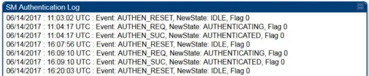
Figure 219 SM Authorization log

Appendix A - 450m Reference information
A.1 Specifications
Please see the Specification sheets listed on the Cambium Networks website for the most up-to-date 450m Series AP specifications:
http://www.cambiumnetworks.com/resource/pmp-450m/
A.2 450m overload
The 450m Series AP is designed to handle high load in terms of high throughput and high PPS. In terms of throughput, 450m is designed to achieve 3x or more throughput improvement over 450 and 450i Series products. In terms of packets per second (PPS), 450m is designed to handle up to 100k PPS.
Overload occurs when the offered load exceeds the above limits. When overload occurs, 450m will start discarding packets and TCP throughput will degrade due to packet loss. The 450 family of products have a set of overload statistics that can be used to monitor overload conditions (Statistics >Overload tab).

The above statistics shall be monitored over time for overload conditions over consecutive periods. Refer to Interpreting Overload statistics for description of those statistics.
It's worth noting that Frame Utilization statistics (Statistics >Frame Utilization tab: Frame Utilization: Downlink and Uplink) are not necessarily indicative of overload condition. They show how much the TDD frame is utilized. High frame utilization depends on:
- high traffic during busy periods: those statistics will be close to 100% and almost all slots will be utilized. In this case if the Overload statistics show that packets are discarded then this is an indication of overload condition.
- high percentage of VCs with low modulation with moderate traffic. Those VCs will require more slots to service them (due to low modulation) and the frame utilization will be high. In this case the TDD frame is fully utilized but the system is at low capacity and is not in an overload condition.
450m has higher PPS than 450 and 450i and supports higher throughput through spatial multiplexing, therefore when a 450m replaces an overloaded 450 or 450i AP the 450m will not be overloaded under the same conditions but the frame utilization may still show close to 100%; this should not alarm the customer. The overload statistics shall be monitored on 450m to see if it is overloaded or not.
Glossary
| Term | Definition | ||||
| 10Base-T | Technology in Ethernet communications that can deliver 10 Mb of data across 328 feet (100 meters) of CAT 5 cable. | ||||
| 169.254.0.0 | Gateway IP address default in Cambium fixed wireless broadband IP network modules. | ||||
| 169.254.1.1 | IP address default in Cambium fixed wireless broadband IP network modules. | ||||
| 255.255.0.0 | Subnet mask default in Cambium fixed wireless broadband IP network modules and in Microsoft and Apple operating systems. | ||||
| 802.3 | An IEEE standard that defines the contents of frames that are transferred through Ethernet connections. Each of these frames contains a preamble, the address to which the frame is sent, the address that sends the frame, the length of the data to expect, the data, and a checksum to validate that no contents were lost. | ||||
| Access Point Cluster | Two to six Access Point Modules that together distribute network or Internet services to a community of subscribers. Each Access Point Module covers a 60° or 90° sector. This cluster covers as much as 360°. Also known as AP cluster. | ||||
| Access Point Module | Also known as AP. One module that distributes network or Internet services in a 60° or 90° sector. | ||||
| ACT/4 | Second-from-left LED in the module. In the operating mode, this LED is lit when data activity is present on the Ethernet link. | ||||
| Address Resolution Protocol | Protocol defined in RFC 826 to allow a network element to correlate a host IP address to the Ethernet address of the host. See http://www.faqs.org/rfcs/rfc826.html. | ||||
| Aggregate Throughput | The sum of the throughputs in the uplink and the downlink. | ||||
| AP | Access Point Module. One module that distributes network or Internet services to subscriber modules. | ||||
| ARP | Address Resolution Protocol. A protocol defined in RFC 826 to allow a network element to correlate a host IP address to the Ethernet address of the host. See http://www.faqs.org/rfcs/rfc826.html. | ||||
| APs MIB | Management Information Base file that defines objects that are specific to the Access Point Module. See also Management Information Base. | ||||
| ASN.1 | Abstract Syntax Notation One language. The format of the text files that compose the Management Information Base. | ||||
| Attenuation | Reduction of signal strength caused by the travel from the transmitter to the receiver, and caused by any object between. In the absence of objects between, a signal that has a short wavelength experiences a high degree of attenuation nevertheless. | ||||
| BER | Bit Error Rate. The ratio of incorrect data received to correct data received. | ||||
| BHM | Backhaul Timing Master (BHM)- a module that is used in a point to point link. This module controls the air protocol and configurations for the link.. | ||||
| BHS | Backhaul Timing Slave (BHS)- a module that is used in a point to point link. This module accepts configuration and timing from the master module. | ||||
| Bit Error Rate | Ratio of incorrect data received to correct data received. | ||||
| Box MIB | Management Information Base file that defines module-level objects. See also Management Information Base. | ||||
| Bridge | Network element that uses the physical address (not the logical address) of another to pass data. The bridge passes the data to either the destination address, if found in the simple routing table, or to all network segments other than the one that transmitted the data. Modules are Layer 2 bridges except that, where NAT is enabled for an SM, the SM is a Layer 3 switch. Compare to Switch and Router, and see also NAT. | ||||
| Buckets | Theoretical data repositories that can be filled at preset rates or emptied when preset conditions are experienced, such as when data is transferred. | ||||
| Burst Preset amount limit of data that may be continuously transferred. | |||||
| CAT 5 Cable | Cable that delivers Ethernet communications from module to module. Later modules auto-sense whether this cable is wired in a straight-through or crossover scheme. | ||||
| CIR | Committed Information Rate. For an SM or specified group of SMs, a level of bandwidth that can be guaranteed to never fall below a specified minimum (unless oversubscribed). In the Cambium implementation, this is controlled by the Low Priority Uplink CIR, Low Priority Downlink CIR, Medium Priority Uplink CIR, Medium Priority Downlink CIR parameters, High Priority Uplink CIR, High Priority Downlink CIR parameters, Ultra High Priority Uplink CIR, and Ultra High Priority Downlink CIR parameters. | ||||
| Cluster Management Module | Module that provides power, GPS timing, and networking connections for an AP cluster. Also known as CMM4. | ||||
| CMM | Cluster Management Module. A module that provides power, GPS timing, and networking connections for an Access Point cluster. | ||||
| CodePoint See DiffServ. | |||||
| Color Code Field | Module parameter that identifies the other modules with which communication is allowed. The range of valid values is 0 to 255. | ||||
| Community String Field | Control string that allows a network management station to access MIB information about the module. | ||||
| Connectorized | The 450 Platform Family Connectorized Radio solution provide RF port to connect external antenna. It gives flexibility to connect to a variety of external antennas. | ||||
| Country Code A parameter that offers multiple fixed selections, each of which automatically implements frequency band range restrictions for the selected country. Units shipped to countries other than the United States must be configured with the corresponding Region Code and Country Code to comply with local regulatory requirements. | |||||
| CRCError Field | This field displays how many CRC errors occurred on the Ethernet controller. | ||||
| Data Encryption Standard | Over-the-air link option that uses secret 56-bit keys and 8 parity bits. Data Encryption Standard (DES) performs a series of bit permutations, substitutions, and recombination operations on blocks of data. | ||||
| Demilitarized Zone | Internet Protocol area outside of a firewall. Defined in RFC 2647. See http://www.faqs.org/rfcs/rfc2647.html. | ||||
| DES | Data Encryption Standard. An over-the-air link option that uses secret 56-bit keys and 8 parity bits. DES performs a series of bit permutations, substitutions, and recombination operations on blocks of data. | ||||
| DFS See Dynamic Frequency Selection | |||||
| DHCP | Dynamic Host Configuration Protocol, defined in RFC 2131. Protocol that enables a device to be assigned a new IP address and TCP/IP parameters, including a default gateway, whenever the device reboots. Thus DHCP reduces configuration time, conserves IP addresses, and allows modules to be moved to a different network within the system. See http://www.faqs.org/rfcs/rfc2131.html. See also Static IP Address Assignment. | ||||
| DiffServ | Differentiated Services, consistent with RFC 2474. A byte in the type of service (TOS) field of packets whose values correlates to the channel on which the packet should be sent. The value is a numeric code point. The PMP 450 AP's support four levels of QoS. The mapping of these eight priority values to data channels is determined by the number of data channels configured per SM as shown in the table below: | ||||
| Number of QoS levels → | 1 | 2 | 3 | 4 | |
| Level 1 | 0-7 | 0-3 | 0-1 | 0-1 | |
| Level 2 | - | 4-7 | 2-3 | 2-3 | |
| Level 3 | - | - | 4-7 | 4-5 | |
| Level 4 | - | - | - | 6-7 | |
| For example, for an AP that uses the default table shown above has configured 3 QoS levels per SM, would see codepoints 0 through 15 mapped to the Low Priority data channels, codepoint 16 would be mapped to the Medium Priority data channels, and so on. Note that CodePoints 0, 8, 16, 24, 32, 48, and 56 are predefined to the fixed values shown in Table 132 and are not user configurable. Operator cannot change any of these fixed priority values. Among the configurable parameters, the priority values (and therefore the handling of packets in the high or low priority channel) are set in the AP/BHM for all downlinks within the sector and in the SM/BHS for each uplink. | |||||
| DMZ Demilitarized Zone as defined in RFC 2647. An Internet Protocol area outside of a firewall. See http://www.faqs.org/rfcs/rfc2647.html. | |||||
| Term | Definition |
| Dynamic Frequency Selection | A requirement in certain countries and regions for systems to detect interference from other systems, notably radar systems, and to avoid co-channel operation with these systems. |
| Dynamic Host Configuration Protocol | See DHCP. |
| Electronic Serial Number | Hardware address that the factory assigns to the module for identification in the Data Link layer interface of the Open Systems Interconnection system. This address serves as an electronic serial number. Same as MAC Address. |
| ESN | Electronic Serial Number. The hardware address that the factory assigns to the module for identification in the Data Link layer interface of the Open Systems Interconnection system. This address serves as an electronic serial number. Same as MAC Address. |
| Ethernet Protocol | Any of several IEEE standards that define the contents of frames that are transferred from one network element to another through Ethernet connections. |
| ETSI | European Telecommunications Standards Institute |
| Fade Margin | The difference between strength of the received signal and the strength that the receiver requires for maintaining a reliable link. A higher fade margin is characteristic of a more reliable link. Standard operating margin. |
| FCC Federal Communications Commission of the U.S.A. | |
| Field-programmable Gate Array | Array of logic, relational data, and wiring data that is factory programmed and can be reprogrammed. |
| File Transfer Protocol | Utility that transfers of files through TCP (Transport Control Protocol) between computing devices that do not operate on the same platform. Defined in RFC 959. See http://www.faqs.org/rfcs/rfc959.html. |
| FPGA | Field-programmable Gate Array. An array of logic, relational data, and wiring data that is factory programmed and can be reprogrammed. |
| Free Space Path Loss | Signal attenuation that is naturally caused by atmospheric conditions and by the distance between the antenna and the receiver. |
| Fresnel Zone | Space in which no object should exist that can attenuate, diffract, or reflect a transmitted signal before the signal reaches the target receiver. |
| FTP | File Transfer Protocol, defined in RFC 959. Utility that transfers of files through TCP (Transport Control Protocol) between computing devices that do not operate on the same platform.See http://www.faqs.org/rfcs/rfc959.html. |
| Global Positioning System | Network of satellites that provides absolute time to networks on earth, which use the time signal to synchronize transmission and reception cycles (to avoid interference) and to provide reference for troubleshooting activities. |
| GPS | Global Positioning System. A network of satellites that provides absolute time to networks on earth, which use the time signal to synchronize transmission and reception cycles (to avoid interference) and to provide reference for troubleshooting activities. |
| GPS/3 | Third-from-left LED in the module. In the operating mode for an Access Point Module, this LED is continuously lit as the module receives sync pulse. In the operating mode for a Subscriber, this LED flashes on and off to indicate that the module is not registered. |
| GUI Graphical user interface. | |
| HTTP | Hypertext Transfer Protocol, used to make the Internet resources available on the World Wide Web. Defined in RFC 2068. See http://www.faqs.org/rfcs/rfc2068.html. |
| HTTPS Hypertext Transfer Protocol Secure (HTTPS) | |
| ICMP | Internet Control Message Protocols defined in RFC 792, used to identify Internet Protocol (IP)-level problems and to allow IP links to be tested. See http://www.faqs.org/rfcs/rfc792.html. |
| Integrated | The 450 Platform Family Integrated Radio solution provides integrated antenna.. |
| IP | Internet Protocol defined in RFC 791. The Network Layer in the TCP/IP protocol stack. This protocol is applied to addressing, routing, and delivering, and re-assembling data packets into the Data Link layer of the protocol stack. See http://www.faqs.org/rfcs/rfc791.html |
| IP Address | 32-bit binary number that identifies a network element by both network and host. See also Subnet Mask. |
| IPv4 | Traditional version of Internet Protocol, which defines 32-bit fields for data transmission. |
| ISM | Industrial, Scientific, and Medical Equipment radio frequency band, in the 900-MHz, 2.4-GHz, and 5.8-GHz ranges. |
| L2TP over IPSec | Level 2 Tunneling Protocol over IP Security. One of several virtual private network (VPN) implementation schemes.Regardless of whether Subscriber Modules have the Network Address Translation feature (NAT) enabled, they support VPNs that are based on this protocol. |
| Late Collision Field | This field displays how many late collisions occurred on the Ethernet controller. A normal collision occurs during the first 512 bits of the frame transmission. A collision that occurs after the first 512 bits is considered a late collision. A late collision is a serious network problem because the frame being transmitted is discarded. A late collision is most commonly caused by a mismatch between duplex configurations at the ends of a link segment. |
| Line of Sight | Wireless path (not simply visual path) direct from module to module. The path that results provides both ideal aim and an ideal Fresnel zone. |
| LNK/5 | Furthest left LED in the module. In the operating mode, this LED is continuously lit when the Ethernet link is present. In the aiming mode for a Subscriber Module, this LED is part of a bar graph that indicates the quality of the RF link. |
| Logical Unit ID | Final octet of the 4-octet IP address of the module. |
| LOS | Line of sight. The wireless path (not simply visual path) direct from module to module. The path that results provides both ideal aim and an ideal Fresnel zone. |
| LUID | Logical Unit ID. The final octet of the 4-octet IP address of the module. |
| MAC Address | Media Access Control address. The hardware address that the factory assigns to the module for identification in the Data Link layer interface of the Open Systems Interconnection system.This address serves as an electronic serial number. |
| Management Information Base | Space that allows a program (agent) in the network to relay information to a network monitor about the status of defined variables (objects). |
| Maximum Information Rate (MIR) | The cap applied to the bandwidth of an SM or specified group of SMs. In the Cambium implementation, this is controlled by the Sustained Uplink Data Rate, Uplink Burst Allocation, Sustained Downlink Data Rate, and Downlink Burst Allocation parameters. |
| MIB Management Information Base. Space that allows a program(agent) in the network to relay information to a network monitor about the status of defined variables (objects). | |
| MIR See Maximum Information Rate. | |
| MU-MIMO | Multi User- Multiple Input Multiple Output |
| NAT | Network Address Translation defined in RFC 1631. A scheme that isolates Subscriber Modules from the Internet. See http://www.faqs.org/rfcs/rfc1631.html |
| NEC | National Electrical Code. The set of national wiring standards that are enforced in the U.S.A. |
| NetBIOS | Protocol defined in RFC 1001 and RFC 1002 to support an applications programming interface in TCP/IP. This interface allows a computer to transmit and receive data with another host computer on the network. RFC 1001 defines the concepts and methods. RFC 1002 defines the detailed specifications. See http://www.faqs.org/rfcs/rfc1001.html and http://www.faqs.org/rfcs/rfc1002.html. |
| Network Address Translation | Scheme that defines the Access Point Module as a proxy server to isolate registered Subscriber Modules from the Internet. Defined in RFC 1631. See http://www.faqs.org/rfc/rfc1631.html. |
| Network Management Station | See NMS. |
| NMS Network Management Station. A monitor device that uses Simple Network Management Protocol (SNMP) to control, gather, and report information about predefined network variables (objects). See also Simple Network Management Protocol. | |
| Default Mode | Device that enables the operator to regain control of a module that has been locked by the No Remote Access feature, the 802.3 Link Disable feature, or a password or IP address that cannot be recalled. This device can be either fabricated on site or ordered. |
| PMP | See Point-to-Multipoint Protocol. |
| Point-to-Multipoint Protocol | Defined in RFC 2178, which specifies that data that originates from a central network element can be received by all other network elements, but data that originates from a non-central network element can be received by only the central network element. See http://www.faqs.org/rfcs/rfc2178.html. Also referenced as PMP. |
| PPPoE | Point to Point Protocol over Ethernet. Supported on SMs for operators who use PPPoE in other parts of their network operators who want to deploy PPPoE to realize per-subscriber authentication, metrics, and usage control. |
| PPS Packet Per Second | |
| PPTP | Point to Point Tunneling Protocol. One of several virtual private network implementations. Regardless of whether the Network Address Translation (NAT) feature enabled, Subscriber Modules support VPNs that are based on this protocol. |
| Protective Earth | Connection to earth (which has a charge of 0 volts). Also known as ground. |
| Proxy Server | Network computer that isolates another from the Internet. The proxy server communicates for the other computer, and sends replies to only the appropriate computer, which has an IP address that is not unique or not registered. |
| PTP | A Point-to-Point connection refers to a communications connection between two nodes or endpoints. |
| Radio Signal Strength Indicator | Relative measure of the strength of a received signal. An acceptable link displays a Radio Signal Strength Indicator (RSSI) value of greater than 700. |
| Reflection | Change of direction and reduction of amplitude of a signal that encounters an object larger than the wavelength. Reflection may cause an additional copy of the wavelength to arrive after the original, unobstructed wavelength arrives. This causes partial cancellation of the signal and may render the link unacceptable. However, in some instances where the direct signal cannot be received, the reflected copy may be received and render an otherwise unacceptable link acceptable. |
| Region Code | A parameter that offers multiple fixed selections, each of which automatically implements frequency band range restrictions for the selected region. Units shipped to regions other than the United States must be configured with the corresponding Region Code to comply with local regulatory requirements. |
| RF | Radio frequency. How many times each second a cycle in the antenna occurs, from positive to negative and back to positive amplitude. |
| RJ-12 | Standard cable that is typically used for telephone line or modem connection. |
| RJ-45 | Standard cable that is typically used for Ethernet connection. This cable may be wired as straight-through or as crossover. Later modules auto-sense whether the cable is straight-through or crossover. |
| Router | Network element that uses the logical (IP) address of another to pass data to only the intended recipient. Compare to Switch and Bridge. |
| RSSI Radio Signal Strength Indicator. A relative measure of the strength of a received signal. An acceptable link displays an RSSI value of greater than 700. | |
| Self-interference | Interference with a module from another module in the same network. |
| SFP | Small Form-factor Pluggable |
| Simple Network Management Protocol | Standard that is used for communications between a program (agent) in the network and a network management station (monitor). Defined in RFC 1157. See http://www.faqs.org/rfcs/rfc1157.html |
| SM | Customer premises equipment (CPE) device that extends network or Internet services by communication with an Access Point Module or an Access Point cluster. |
| SNMP | See Simple Network Management Protocol, defined in RFC 1157. |
| SNMPv3 SNMP version 3 | |
| SNMP Trap | Capture of information that informs the network monitor through Simple Network Management Protocol of a monitored occurrence in the module. |
| Spatial Frequency | Spatial Frequency is associated with an LUID or SM registered with an AP and it is visible on both AP and SM GUIs. It is grouped into bins where each bin includes 32 consecutive spatial frequency values. |
| Static IP Address Assignment | Assignment of Internet Protocol address that can be changed only manually. Thus, static IP address assignment requires more configuration time and consumes more of the available IP addresses than DHCP address assignment does. RFC 2050 provides guidelines for the static allocation of IP addresses. See http://www.faqs.org/rfcs/rfc2050.html. See also DHCP. |
| Subnet Mask | 32-bit binary number that filters an IP address to reveal what part identifies the network and what part identifies the host. The number of subnet mask bits that are set to 1 indicates how many leading bits of the IP address identify the network. The number of subnet mask bits that are set 0 indicate how many trailing bits of the IP address identify the host. |
| Subscriber Module | Customer premises equipment (CPE) device that extends network or Internet services by communication with an Access Point Module or an Access Point cluster. |
| Sustained Data Rate | Preset rate limit of data transfer. |
| Switch | Network element that uses the port that is associated with the physical address of another to pass data to only the intended recipient. Compare to Bridge and Router. |
| Sync | GPS (Global Positioning System) absolute time, which is passed from one module to another. Sync enables timing that prevents modules from transmitting or receiving interference. Sync also provides correlative time stamps for troubleshooting efforts. |
| TCP Alternatively known as Transmission Control Protocol or Transport Control Protocol. The Transport Layer in the TCP/IP protocol stack. This protocol is applied to assure that data packets arrive at the target network element and to control the flow of data through the Internet. Defined in RFC 793. See http://www.faqs.org/rfcs/rfc793.html | |
| TDD | Time Division Duplexing. Synchronized data transmission with some time slots allocated to devices transmitting on the uplink and some to the device transmitting on the downlink. |
| telnet | Utility that allows a client computer to update a server. A firewall can prevent the use of the telnet utility to breach the security of the server. See http://www.faqs.org/rfcs/rfc818.html. http://www.faqs.org/rfcs/rfc854.html and http://www.faqs.org/rfcs/rfc855.html. |
| Tokens | Theoretical amounts of data. See also Buckets. |
| TxUnderrun Field | This field displays how many transmission-underrun errors occurred on the Ethernet controller. |
| UDP User Datagram Protocol. A set of Network, Transport, and Session Layer protocols that RFC 768 defines. These protocols include checksum and address information but does not retransmit data or process any errors. See http://www.faqs.org/rfcs/rfc768.htmludp User-defined type of port. | |
| U-NII | Unlicensed National Information Infrastructure radio frequency band, in the 5.1GHz through 5.8 GHz ranges. |
| VID | VLAN identifier. See also VLAN. |
| VLAN | Virtual local area network. An association of devices through software that contains broadcast traffic, as routers would, but in the switch-level protocol. |
| VPN Virtual private network for communication over a public network. One typical use is to connect remote employees, who are at home or in a different city, to their corporate network over the Internet. Any of several VPN implementation schemes is possible. SMs support L2TP over IPSec (Level 2 Tunneling Protocol over IP Security) VPNs and PPTP (Point to Point Tunneling Protocol) VPNs, regardless of whether the Network Address Translation (NAT) feature enabled. | |
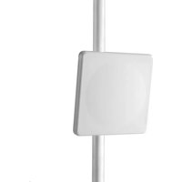


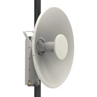
- Cambium Networks™
- USER GUIDE
- PMP/PTP 450 Series
- Accuracy
- Copyrights
- Restrictions
- License Agreements
- High Risk Materials
- Contents
- Antennas and antenna cabling....2-54
- GPS synchronization....2-56
- Installing a GPS receiver....2-71
- Ordering the components....2-74
- Chapter 3: System planning....3-1
- Typical deployment....3-2
- Site planning....3-7
- Radio Frequency planning....3-18
- List of Figures
- List of Tables
- About This User Guide
- Contacting Cambium Networks
- Purpose
- Product notation conventions in document
- Cross references
- Feedback
- Important regulatory information
- Application software
- USA specific information
- Caution
- External antennas
- Avoidance of weather radars (USA only)
- Canada specific information
- ISEDC Approved Antennas
- Antennas externes
- EU Declaration of Conformity
- Specific expertise and training for professional installers
- Ethernet networking skills
- Lightning protection
- Training
- Reporting problems
- Repair and service
- Hardware warranty
- Security advice
- Warnings, cautions, and notes
- Warnings
- Cautions
- Notes
- Caring for the environment
- In EU countries
- Disposal of Cambium equipment
- Disposal of surplus packaging
- In non-EU countries
- Chapter 1: Product description
- Overview of the 450 Platform Family
- Platform Family
- PMP 450m Series
- Key features
- Frequency bands
- Hardware components
- PMP/PTP 450i Series
- Note
- PMP/PTP 450b Series
- Supported interoperability for 450m/450i/450b/450 Series
- Typical deployment
- Point-to-Multipoint
- Point-to-Point (Backhaul)
- Product variants
- Wireless operation
- Time division duplexing
- TDD frame parameters
- OFDM and channel bandwidth
- Cyclic Prefix
- Frame Period
- Frame configuration - Downlink Data
- Link operation - Dynamic Rate Adapt
- Encryption
- MIMO
- MU-MIMO
- System management
- Management agent
- Web server
- Web pages
- Identity-based user accounts
- Remote Authentication Dial-in User Service (RADIUS)
- Network Time Protocol (NTP)
- cnMaestro™
- Wireless Manager (WM)
- Canopy Network Updater Tool (CNUT)
- Radio recovery mode
- Radio Recovery Console - 450i, 450b and 450m Series
- Default Mode (or Default Plug) - 450 Series
- Chapter 2: System hardware
- System Components
- Point-to-Multipoint (PMP)
- PMP 450 Platform Family Integrated or Connectorized ODU
- Backhaul (PTP)
- PTP 450 Platform Family Integrated or Connectorized ODU
- Platform Family interfaces
- PMP 450m Series interfaces - AP - 3GHz
- PMP 450m Series interfaces - AP - 5 GHz
- PMP/PTP 450i Series interfaces - AP/SM/BH
- PMP/PTP 450b Mid-Gain Series interfaces - SM
- PMP/PTP 450b High Gain Series interfaces - SM
- PMP/PTP 450 Series interfaces - AP
- PMP/PTP 450 Series interfaces - SM/BH
- ATEX/HAZLOC variants
- Diagnostic LEDs
- AP/BHM LEDs
- SM/BHS LEDs
- Operating Mode
- Aiming Mode
- Power supply options
- Power supply - PMP 450m Series
- PSU part numbers
- Power supply - PMP/PTP 450i Series
- AC Power Injector N000065L001B
- AC+DC Enhanced Power Injector C000065L002C
- -48 VDC Power Injector N000000L036A
- Power supply - PMP/PTP 450b Series
- Power supply - PMP/PTP 450 Series
- Warning
- Gigabit Enet Capable Power Supply
- ODU mounting brackets & accessories
- ODU interfaces
- PMP 450m Series 5 GHz AP
- PMP 450m Series 3GHz AP
- PMP/PTP 450i
- PMP/PTP 450b Mid-Gain SM
- PMP/PTP 450b High Gain SM
- Cabling
- Ethernet standards and cable lengths
- Outdoor copper Cat5e Ethernet cable
- SFP module kits
- Main Ethernet port
- Aux port
- Aux port to alignment tone headset wiring
- RJ45 connectors and spare glands
- Ethernet cable testing
- Lightning protection unit (LPU) and grounding kit
- DC LPU and Grounding Kit
- Cable grounding kit
- Antennas and antenna cabling
- Antenna requirements
- Supported external AP antennas
- Supported external BH/SM antenna
- RF cable and connectors
- Antenna accessories
- GPS synchronization
- GPS synchronization description
- Universal GPS (UGPS)
- CMM5
- Cluster Management: Scenario 1
- Cluster Management: Scenario 2
- CMM5 Controller Module
- CMM5 Injector Module
- CMM5 Injector Compatibility Matrix
- CMM5 Specifications
- CMM4 (Rack Mount)
- CMM4 56 V power adapter cable pinout
- CMM4 (Cabinet with switch)
- CMM4 (Cabinet without switch)
- CMM3/CMMmicro
- Installing a GPS receiver
- GPS receiver location
- Mounting the GPS receiver module on the equipment building
- Mounting the GPS receiver module on a metal tower or mast
- Mounting the GPS receiver
- Procedure 1 Mounting the GPS receiver
- Cabling the GPS Antenna
- Installing and connecting the GPS LPU
- Ordering the components
- PMP 450m
- PMP 450i
- PTP 450i
- PMP 450b
- PTP 450b
- PMP 450
- PTP 450
- PMP/PTP 450/450i Series Accessories
- Chapter 3: System planning
- ODU with PoE interface to PSU
- Site planning
- Site selection for PMP/PTP radios
- Power supply site selection
- Maximum cable lengths
- Grounding and lightning protection
- Lightning protection zones
- Site grounding system
- ODU and external antenna location
- ODU ambient temperature limits
- ODU wind loading
- Hazardous locations
- Drop cable grounding points
- Lightning Protection Unit (LPU) location
- Radio Frequency planning
- Regulatory limits
- Conforming to the limits
- Available spectrum
- Analyzing the RF Environment
- Channel bandwidth
- Anticipating Reflection of Radio Waves
- Obstructions in the Fresnel Zone
- Planning for co-location
- Multiple OFDM Access Point Clusters
- Considerations on back-to-back frequency reuse
- Reflecting objects
- Reflection likelihood guidance
- PMP 450m installation recommendations
- Link planning
- Range and obstacles
- Path loss
- Calculating Link Loss
- Calculating Rx Signal Level
- Calculating Fade Margin
- Adaptive modulation
- Planning for connectorized units
- When to install connectorized units
- Choosing external antennas
- Calculating RF cable length (5.8 GHz FCC only)
- Data network planning
- Understanding addresses
- IP address
- Dynamic or static addressing
- When a DHCP server is not found
- DNS Client
- Network Address Translation (NAT)
- NAT, DHCP Server, DHCP Client and DMZ in SM
- NAT
- DHCP
- DMZ
- Developing an IP addressing scheme
- Address Resolution Protocol
- Allocating subnets
- Example IP address and subnet mask
- Selecting non-routable IP addresses
- Translation bridging
- Engineering VLANs
- Special case VLAN numbers
- SM membership in VLANs
- Priority on VLANs (802.1p)
- Q-in-Q DVLAN (Double-VLAN) Tagging (802.1ad)
- Network management planning
- Planning for SNMP operation
- Enabling SNMP
- Security planning
- Isolating AP/BHM from the Internet
- Encrypting radio transmissions
- Planning for HTTPS operation
- Planning for SNMPv3 operation
- SNMP security mode
- Web-based management of SNMPv3 security
- Managing module access by passwords
- Planning for RADIUS operation
- Filtering protocols and ports
- Port Filtering with NAT Enabled
- Protocol and Port Filtering with NAT Disabled
- Port Configuration
- Encrypting downlink broadcasts
- Isolating SMs in PMP
- Filtering management through Ethernet
- Allowing management from only specified IP addresses
- Configuring management IP by DHCP
- DHCP option 81
- Controlling PPPoE PADI Downlink Forwarding
- Remote AP Deployment
- Remote AP (RAP) Performance
- Example Use Case for RF Obstructions
- Example Use Case for Passing Sync
- Physical Connections Involving the Remote AP
- Passing Sync signal
- Passing Sync in a Single Hop
- Passing Sync in an Additional Hop
- - Design 4
- - Design 5
- Wiring to Extend Network Sync
- Chapter 4: Legal and regulatory information
- Attention
- Cambium Networks end user license agreement
- Definitions
- Acceptance of this agreement
- Grant of license
- Conditions of use
- Title and restrictions
- Confidentiality
- Right to use Cambium's name
- Transfer
- Updates
- Maintenance
- Disclaimer
- Limitation of liability
- U.S. government
- Term of license
- Governing law
- Assignment
- Survival of provisions
- Entire agreement
- Third party software
- Net SNMP
- OpenSSL
- Zlib
- Libpng
- Bzip2
- USB library functions
- Apache
- END OF TERMS AND CONDITIONS
- D3 JS library
- Compliance with safety standards
- Electrical safety compliance
- Electromagnetic compatibility (EMC) compliance
- Human exposure to radio frequency energy
- Power density exposure limit
- Calculation of power density
- Where: Is:
- Calculated distances and power compliance margins
- Remarque
- Hazardous location compliance
- ATEX
- Compliance with radio regulations
- Brazil specific information
- Brazil notification
- Brazil certification numbers
- Australia Notification
- Regulatory Requirements for CEPT Member States (www.cept.org)
- Chapter 5: Preparing for installation
- Safety
- Power lines
- Working at heights
- Power supply
- Grounding and protective earth
- Powering down before servicing
- Primary disconnect device
- External cables
- RF exposure near the antenna
- Minimum separation distances
- Grounding and lightning protection requirements
- Grounding cable installation methods
- Siting ODUs and antennas
- Thermal Safety
- Alerte
- Preparing for installation
- ODU pre-configuration
- Preparing personnel
- Preparing inventory
- Preparing tools
- Testing system components
- Unpacking Components
- Preparing the ODU
- Configuring the Computing Device for Test
- Factory default Configuration
- ODU diagnostic LEDs
- Recommended Tools for Installation
- Standards for Wiring
- Best Practices for Cabling
- Wiring Connectors
- Main port pinout
- Aux port pinout
- RJ-45 Pinout for Straight-through Ethernet Cable
- RJ-45 Pinout for Crossover Ethernet Cable
- AP/BHM to UGPS cable
- Alignment tone cable (for PMP/PTP 450i)
- Override plug cable (for PMP 450 only)
- Configuring Link for Test
- Configuring the management PC
- Powering the AP/SM/BH for test configuration
- Procedure 2 Powering the ODU
- Procedure 3 Bypassing browser proxy settings to access module web pages
- Logging into the web interface - AP/SM/BH
- Procedure 4 Logging into the web interface
- Using the Quick Start Configuration Wizard of the AP/BHM
- Chapter 6: Installation
- ODU variants and mounting bracket options
- Mounting bracket- PMP/PTP 450i Series
- Mounting bracket- PMP 450 Series - SM 900 MHz
- Mount the ODU, LPU and surge suppressor
- Attach ground cables to the ODU
- PMP 450m Series - AP
- PMP/PTP 450i Series - AP/SM/BH, PMP 450 3GHz Ruggedized SM
- PMP 450 AP
- PMP 450 SM
- Mount the ODU on the mast
- PMP/PTP 450i Series - AP/SM/BH, PMP 450 3 GHz Ruggedized SM
- PMP 450b Mid-Gain SM
- PMP 450b High Gain SM
- PMP 450 SM (except PMP 450 SM - 900 MHz)
- PMP 450 SM 900 MHz (connectorized)
- Mount the top LPU
- Mount the Surge Suppressor
- PMP/PTP 450i/450b Series
- Key to Callouts 600SSH
- General protection installation
- Grounding cable requirements
- Basic requirements
- Protection requirements for a wall installation
- Protection requirements for a mast or tower installation
- Protection requirements on a multi-floor building
- Installing the copper Cat5e Ethernet interface
- Install the main drop cable
- Cut to length and fit hoisting grips
- Terminate with RJ45 connectors
- Install the bottom LPU to PSU drop cable
- Install the bottom LPU
- Install the LPU to PSU drop cable
- Installing external antennas to a connectorized ODU
- PMP 450i Series
- Assembling the PMP 450i AP 5 GHz sector antenna and attaching to the radio
- PMP 450 Series
- Assembling the PMP 450 AP antenna
- Attaching the PMP 450 AP to the antenna
- Attaching the PMP 450 Series AP and antenna to the mount point
- PMP 450i Series AP 900 MHz
- Mounting of PMP 450i AP 900 MHz
- Mounting of PMP 450i AP 900 MHz antenna to the pole
- Sector antenna alignment
- Figure 112 900 MHz sector antenna alignment
- PMP 450 Series SM 900 MHz
- Attaching the SM 900 MHz directional antenna to the pole
- Radio mounting to the antenna
- Directional Yagi antenna alignment
- Installing an integrated ODU
- PMP 450m Series - 5 GHz AP
- PMP 450m Series - 3 GHz AP
- PMP/PTP 450i Series - AP/SM/BH
- Connecting Cat5e Ethernet cable
- Connecting an RJ45 and gland to a unit
- Disconnecting an RJ45 and gland from a unit
- Installing ODU
- Installing a 450 Platform Family AP
- Procedure 5 Installing an AP
- Installing a 450 Platform Family SM
- Procedure 6 Installing an SM
- Installing a 450 Platform Family BHM
- Procedure 7 Installing a BHM
- Installing a 450 Platform Family BHS
- Procedure 8 Installing a BHS
- Configuring the Link
- Monitoring the Link
- Installing the AC Power Injector
- Installing CMM4
- The CMM4 provides:
- Supplemental installation information
- Stripping drop cable
- Creating a drop cable grounding point
- Attaching and weatherproofing an N type connector
- Chapter 7: Configuration
- Preparing for configuration
- Safety precautions
- Regulatory compliance
- Connecting to the unit
- Procedure 9 Configuring the management PC
- Connecting to the PC and powering up
- Procedure 10 Connecting to the PC and powering up
- Using the web interface
- Logging into the web interface
- Procedure 11 Logging into the web interface
- Web GUI
- Using the menu options
- Quick link setup
- Initiating Quick Start Wizard
- Procedure 12 Quick start wizard
- Configuring time settings
- Procedure 13 Entering AP/BHM time setup information
- Powering the SM/BHS for test
- Procedure 14 Powering the SM/BHS for test
- Viewing the Session Status of the AP/BHM to determine test registration
- Procedure 15 Viewing the AP Session Status page
- Configuring IP and Ethernet interfaces
- Configuring the IP interface
- Procedure 16 Configuring the AP/BHM IP interface
- Auxiliary port
- Procedure 17 Enabling Aux port interface
- NAT, DHCP Server, DHCP Client and DMZ
- NAT Disabled
- NAT with DHCP Client and DHCP Server
- NAT with DHCP Client
- NAT with DHCP Server
- NAT without DHCP
- NAT and VPNs
- IP interface with NAT disabled - SM
- IP interface with NAT enabled - SM
- NAT tab with NAT disabled - SM
- NAT tab with NAT enabled - SM
- NAT DNS Considerations - SM
- DHCP - BHS
- Reconnecting to the management PC
- VLAN configuration for PMP
- VLAN Remarking
- VLAN ID Remarking
- 802.1P Remarking
- VLAN Priority Bits configuration
- Default Port VID
- MAC Address Mapped VID
- Provider VID
- Management VID
- Use AP's Management VID for ICC connected SM
- VLAN page of AP
- VLAN page of SM
- VLAN Membership tab of SM
- VLAN configuration for PTP
- VLAN page of BHM
- VLAN page of BHS
- PPPoE page of SM
- IP4 and IPv6
- IPv4 and IPv6 Prioritization
- IPv4 and IPv6 Filtering
- Upgrading the software version and using CNUT
- Checking the installed software version
- Procedure 18 Checking the installed software version
- Upgrading to a new software version
- CNUT functions
- Network element groups
- Network layers
- Script engine
- Software dependencies for CNUT
- CNUT functionality requires
- CNUT download
- Upgrading a module prior to deployment
- Procedure 19 Upgrading a module prior to deployment
- General configuration
- PMP 450m and PMP/PTP 450i Series
- General page - PMP 450i AP
- General page - PMP 450m AP
- General page - PMP 450i SM
- General page - PTP 450i BHM
- General page - PTP 450i BHS
- General page - PMP/PTP 450b SM/Backhaul
- General page - PMP 450 AP
- General page - PMP 450 SM
- General page - PTP 450 BHM
- General page - PTP 450 BHS
- Configuring Unit Settings page
- Unit Settings page of 450 Platform Family - AP/BHM
- Unit Settings page of PMP/PTP 450i SM/BHS
- Setting up time and date
- Time page of 450 Platform Family - AP/BHM
- Configuring synchronization
- AutoSync
- AutoSync + Free Run
- Generate Sync (factory default)
- Configuring security
- Managing module access by password
- Adding a User for Access to a module
- Deleting a User from Access to a module
- Changing a User Setting
- Users account
- Overriding Forgotten IP Addresses or Passwords on AP and SM
- Isolating from the internet - APs/BHMs
- Requiring SM Authentication
- Protocol filtering page of 450 Platform Family AP/BHM
- Protocol filtering page of SM/BHS
- Isolating SMs
- Allowing management only from specified IP addresses
- Restricting radio Telnet access over the RF interface
- Key Security Considerations when using the RF Telnet Access Feature
- Securing AP Clusters
- Restricting AP RF Telnet Access
- Controlling RF Telnet Access via the AP GUI
- Procedure 20 Restricting RF Telnet access
- Configuring SNMP Access
- Procedure 21 Configuring SNMPv3
- SNMPv3 Read-Only and Read/Write User
- SNMPv3 Trap Configuration
- Security page - 450 Platform Family AP
- Security page - 450 Platform Family BHM
- Security page - 450 Platform Family SM
- Security page -450 Platform Family BHS
- Configuring radio parameters
- PMP 450m Series - configuring radio
- Radio page - PMP 450m AP 5 GHz
- Radio page - PMP 450m AP 3 GHz
- PMP/PTP 450i Series - configuring radio
- Radio page - PMP 450i AP 3 GHz
- Radio page - PMP 450i AP 5 GHz
- Radio page - PMP 450i SM 3 GHz
- Radio page - PMP 450i SM 5 GHz
- Radio page - PMP 450i AP 900 MHz
- Radio page - PTP 450i BHM 5 GHz
- Radio page - PTP 450i BHS 5 GHz
- PMP/PTP 450b Series - configuring radio
- Radio page - PMP/PTP 450b Mid-Gain/High Gain SM 5 GHz
- PMP/PTP 450 Series - configuring radio
- Radio page - PMP 450 AP 5 GHz
- Radio page - PMP 450 AP 3.65 GHz
- Radio page - PMP 450 AP 3.5 GHz
- Radio page - PMP 450 AP 2.4 GHz
- Radio page - PMP 450 SM 5 GHz
- Radio page - PMP 450 SM 3.65 GHz
- Radio page - PMP 450 SM 3.5 GHz
- Radio page - PMP 450 SM 2.4 GHz
- Radio page - PMP 450 SM 900 MHz
- Radio page - PTP 450 BHM 5 GHz
- Attribute
- Meaning
- Radio page - PTP 450 BHS 5 GHz
- Radio Frequency Scan Selection List
- Dedicated Multicast Virtual Circuit (VC)
- Custom Frequencies page
- DFS for 5 GHz Radios
- DFS operation
- Contention slots
- Random access
- Selection of contention slots parameter
- Number of SMs in a sector
- Type of traffic in a sector
- Recommendation on Contention Slots number selection
- Cluster of APs
- Frame calculator for co-location
- Basic rules
- Steps for co-location
- Example
- Cambium co-location tool
- MIMO-A mode of operation
- System Performance
- Guard Band
- Improved PPS performance of 450 Platform Family
- Setting up SNMP agent
- Configuring SM/BHS's IP over-the-air access
- Configuring SNMP
- SNMP page - AP/SM/BHM/BHS
- Configuring syslog
- Syslog event logging
- Configuring system logging
- Syslog page of AP/BHM
- Syslog page of SM
- Syslog page of BHS
- Configuring remote access
- Accessing SM/BHS over-the-air by Web Proxy
- Link monitoring procedure
- Procedure 22 Monitoring the AP-SM link
- Exporting Session Status page of AP/BHM
- Export from command line
- Configuring quality of service
- Maximum Information Rate (MIR) Parameters
- Token Bucket Algorithm
- MIR Data Entry Checking
- Committed Information Rate (CIR)
- Bandwidth from the SM Perspective
- Interaction of Burst Allocation and Sustained Data Rate Settings
- SM Prioritization
- SM Prioritization with CIR
- Weighted Fair Queuing (WFQ)
- WFQ with CIR
- WFQ with SM Prioritization
- High-priority Bandwidth Traffic
- Traffic Scheduling
- Setting the Configuration Source
- Configuring Quality of Service (QoS)
- Quality of Service (QoS) page of AP
- Quality of Service (QoS) page of SM
- Quality of Service (QoS) page of BHM
- Quality of Service (QoS) page of BHS
- Installation Color Code
- Zero Touch Configuration Using DHCP Option 66
- Configuration Steps
- Procedure 23 Zero Touch Configuration steps
- Creating a Golden config file
- Hosting the config file
- DHCP server configuration
- Procedure 24 DHCP server configuration
- Supported URL Formats
- Troubleshooting
- Configuring Radio via config file
- Import and Export of config file
- Procedure 25 DHCP server configuration
- Procedure 26 Import the configuration from the GUI
- Procedure 27 Special Headers for configuration file
- Configuring cnMaestro™ Connectivity
- Onboarding
- Prerequisites for onboarding to cnMaestro™
- Knowledge Based articles for onboarding
- Order of Device Onboarding
- Device Agent Logs
- Monitoring Tools for PMP Devices on cnMaestro™
- Zero Touch on boarding of the PMP SMs when the corresponding AP is on boarded
- Configuring a RADIUS server
- Understanding RADIUS for PMP 450 Platform Family
- RADIUS Functions
- Tested RADIUS Servers
- Choosing Authentication Mode and Configuring for Authentication Servers - AP
- SM Authentication Mode - Require RADIUS or Follow AP
- SM - Phase 1 (Outside Identity) parameters and settings
- SM - Phase 2 (Inside Identity) parameters and settings
- Handling Certificates
- Managing SM Certificates via the SM GUI
- Configuring RADIUS servers for SM authentication
- Assigning SM management IP addressing via RADIUS
- Configuring RADIUS server for SM configuration
- Configuring RADIUS server for SM configuration using Zero Touch feature
- Using RADIUS for centralized AP and SM user name and password management
- AP - Technician/Installer/Administrator Authenti cation
- User administration and authentication separation
- Procedure 29 User administration and authentication separation
- SM - Technician/Installer/Administrator Authenti cation
- Access Tracking
- RADIUS Device Data Accounting
- RADIUS Device Re-authentication
- RADIUS Change of Authorization and Disconnect Message
- Microsoft RADIUS support
- SM Authentication Configuration
- Windows Server Configuration
- User Authentication Configuration
- Enabling EAP-MD5
- User Configuration in Active Directory
- RADIUS VSA Configuration
- Accounting
- Cisco ACS RADIUS Server Support
- Adding RADIUS client
- Creating Users
- Creating RADIUS instance
- RADIUS protocols
- Service selection
- Adding Trusted CA
- Installing Server Certificate
- Monitoring Logs
- Configuring VSA
- Using VSA for users
- Change condition to User name
- Next click Create and then click Select see diagram below
- Click Create from the screen you get following screen
- Fill attribute which all you want for that particular user
- Now you are ready to use this Authorization profile for the use Select and Press OK
- Configuring Ping Watchdog
- Chapter 8: Tools
- Using Spectrum Analyzer tool
- Mapping RF Neighbor Frequencies
- Spectrum Analyzer tool
- Analyzing the spectrum
- Procedure 30 Analyzing the spectrum
- Graphical spectrum analyzer display
- Spectrum Analyzer page of AP
- Spectrum Analyzer page of SM
- Spectrum Analyzer page of BHM
- Spectrum Analyzer page of BHS
- Spectrum Analyzer page result of PMP 450 SM
- Remote Spectrum Analyzer tool
- Analyzing the spectrum remotely
- Procedure 31 Remote Spectrum Analyzer procedure
- Remote Spectrum Analyzer page of AP
- Remote Spectrum Analyzer page of BHM
- Using the Alignment Tool
- Aiming page and Diagnostic LED - SM/BHS
- Aiming page of SM
- Aiming page of BHS
- Alignment Tone
- Using the Link Capacity Test tool
- Performing Link Test
- Link Test with Multiple LUIDs
- Procedure 32 Performing a Link Capacity Test - Link Test with Multiple LUIDs
- Link Test Configurations parameters
- Link Test Settings parameters
- Link Test without Bridging, Link Test with Bridging or Link Test with Bridging and MIR
- Performing Extrapolated Link Test
- Procedure 33 Performing an Extrapolated Link Test
- Link Capacity Test page of AP
- Link Capacity Test page of BHM/BHS/SM
- Using AP Evaluation tool
- AP Evaluation page
- Using BHM Evaluation tool
- BHM Evaluation page of BHS
- Using the OFDM Frame Calculator tool
- Procedure 34 Using the Frame Calculator
- Using the Subscriber Configuration tool
- Using the Link Status tool
- Link Status - AP/BHM
- Link Status - SM/BHS
- Using BER Results tool
- Using the Sessions tool
- Using the Ping Test tool
- Chapter 9: Operation
- System information
- Viewing General Status
- General Status page of AP
- General Status page - SM
- General Status page of BHM
- General Status page of BHS
- Viewing Session Status
- Device tab
- Session tab
- Power tab
- Configuration tab
- Link Quality tab
- Viewing Remote Subscribers
- Interpreting messages in the Event Log
- Time and Date Stamp
- Event Log Data Collection
- Messages that Flag Abnormal Events
- Messages that Flag Normal Events
- Viewing the Network Interface
- Viewing the Layer 2 Neighbors
- System statistics
- Viewing the Scheduler statistics
- Viewing list of Registration Failures statistics
- SM Registration Failures page of AP
- BHS Registration Failures page of BHM
- Interpreting Bridging Table statistics
- Interpreting Translation Table statistics
- Interpreting Ethernet statistics
- Interpreting RF Control Block statistics
- Interpreting Sounding statistics for AP
- Interpreting VLAN statistics
- Interpreting Data Channels statistics
- Interpreting MIR/Burst statistics
- Interpreting Throughput statistics
- Board Performance statistics
- Board Throughput statistics
- LUID RF Throughput statistics
- Interpreting Overload statistics
- 450m Overload:
- Interpreting DHCP Relay statistics
- Interpreting Filter statistics
- Viewing ARP statistics
- Viewing NAT statistics
- Viewing NAT DHCP Statistics
- Interpreting Sync Status statistics
- Interpreting PPPoE Statistics for Customer Activities
- Interpreting Bridge Control Block statistics
- Interpreting Pass Through Statistics
- Interpreting SNMPv3 Statistics
- Interpreting syslog statistics
- Interpreting Frame Utilization statistics
- Radio Recovery
- This section describes:
- Radio Recovery Console- PMP/PTP 450i/450b and PMP 450m
- Options in recovery mode are:
- Procedure 35 Radio Recovery Console
- Default Mode (or Default/Override Plug) - PMP/PTP 450 Series
- Using the Default/Override Plug
- Procedure 36 Default mode
- Chapter 10: Reference information
- Equipment specifications
- Specifications for 5 GHz PMP 450m Series - AP
- Specifications for 3 GHz PMP 450m Series - AP
- Specifications for PMP 450i Series - AP
- Specifications for PMP 450i Series - SM
- Specifications for PTP 450i Series - BH
- Specifications for PMP/PTP 450b Mid-Gain Series - SM
- Specifications for PMP/PTP 450b High Gain Series - SM
- Specifications for PMP 450 Series - AP
- Specifications for PMP 450 Series - SM
- Specifications for PTP 450 Series - BH
- PSU specifications
- Data network specifications
- Ethernet interface
- 450m/450i Series
- 450/450b Series
- Wireless specifications
- General wireless specifications
- Link Range and Throughput
- Country specific radio regulations
- Type approvals
- DFS for 2.4 and 5 GHz Radios
- Equipment Disposal
- Waste (Disposal) of Electronic and Electric Equipment
- Country specific maximum transmit power
- Maximum transmit power 900 MHz band
- Maximum transmit power 2.4 GHz band
- Maximum transmit power 3.5 GHz band
- Maximum transmit power 3.65 GHz band
- Maximum transmit power 4.9 GHz band
- Maximum transmit power 5.1 GHz band
- Maximum transmit power 5.2 GHz band
- Maximum transmit power 5.4 GHz band
- Maximum transmit power 5.8 GHz band
- Country specific frequency range
- Frequency range 900 MHz band
- Frequency range 2.4 GHz band
- Frequency range 3.5 GHz band
- Frequency range 3.65 GHz band
- Frequency range 4.9 GHz band
- Frequency range 5.1 GHz band
- Frequency range 5.2 GHz band
- Frequency range 5.4 GHz band
- Frequency range 5.8 GHz band
- FCC specific information
- FCC compliance testing
- FCC IDs
- FCC approved antenna list
- Innovation Science and Economic Development Canada (ISEDC) specific information
- MHz ISEDC notification
- GHz ISEDC notification
- GHz and 5.4 GHz ISEDC notification
- Utilisation de la bande 5.2 and 5.4 GHz ISEDC
- ISEDC notification 5.8 GHz
- ISEDC certification numbers
- Canada approved antenna list
- Chapter 11: Troubleshooting
- General troubleshooting procedure
- General planning for troubleshooting
- General fault isolation process
- Questions to help isolate the problem
- Secondary Steps
- Troubleshooting procedures
- Module has lost or does not establish connectivity
- Procedure 37 Troubleshooting loss of connectivity
- On the SM end of the link:
- On each end of the link:
- NAT/DHCP-configured SM has lost or does not establish connectivity
- Procedure 38 Troubleshooting loss of connectivity for NAT/DHCP-configured SM
- SM Does Not Register to an AP
- Procedure 39 Troubleshooting SM failing to register to an AP
- Module has lost or does not gain sync
- Procedure 40 Troubleshooting loss of sync
- Module does not establish Ethernet connectivity
- Procedure 41 Troubleshooting loss of Ethernet connectivity
- CMM4 does not pass proper GPS sync to connected modules
- Procedure 42 Troubleshooting CMM4 not passing sync
- Module Software Cannot be Upgraded
- Procedure 43 Troubleshooting an unsuccessful software upgrade
- Module Functions Properly, Except Web Interface Became Inaccessible
- Procedure 44 Restoring web management GUI access
- Power-up troubleshooting
- Registration and connectivity troubleshooting
- SM/BMS Registration
- Logs
- Persistent Logging
- Appendix A - 450m Reference information
- A.1 Specifications
- A.2 450m overload
Brand : Cambium Networks
Model : PMP 450b
Category : Network Equipment