
99-5849CH - Car kit Axxess - Free user manual and instructions
Find the device manual for free 99-5849CH Axxess in PDF.


| Product Type | Dash Installation Kit |
| Brand | AXESS |
| Model | 99-5849CH |
| Compatible Vehicles | Ford F-150 2015-2020, F-250/350/450/550 XL 2020-2022 (with 4.2-inch color screen and single zone climate controls) |
| Radio Provision | ISO DIN with pocket, ISO DDIN |
| Color / Finish | Painted charcoal |
| Included Interface | Axxess interface for climate and steering wheel functions |
| Accessory Power Output | 12V DC, 10A |
| Retained Features | R.A.P., steering wheel audio controls, factory backup camera, balance/fade (excluding Sony) |
| Additional Outputs | NAV outputs (parking brake, reverse, speed sense), STOP/START override |
| Antenna Adapter | Included |
| USB Hub Compatibility | AXFD-USB or AXFD-USB2 (sold separately) |
| Tools Required | Panel removal tool, Phillips screwdriver, 9/32" socket wrench, cutting tool |
| Installation Precautions | Disconnect negative battery terminal before installation |
| Programming Method | Configuration menu via steering wheel buttons |
| Maintenance | Clean with soft, dry cloth |
| Safety | Ensure all connections secure, especially airbag indicator lights, before reconnecting battery |
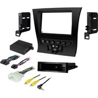
| Included Components | Radio trim panel, radio brackets, pocket, heated seat buttons/blank panels, screws (4), panel clips (6), HVAC interface and wiring harness, antenna adapter |
| Additional Interface Required for B&O Systems | Part #AXA2B-FD1 (sold separately) |
| Excluded Features | Pro Trailer Backup Assist, massaging seats |
Frequently Asked Questions - 99-5849CH Axxess
User questions about 99-5849CH Axxess
0 question about this device. Answer the ones you know or ask your own.
Ask a new question about this device
Download the instructions for your Car kit in PDF format for free! Find your manual 99-5849CH - Axxess and take your electronic device back in hand. On this page are published all the documents necessary for the use of your device. 99-5849CH by Axxess.
USER MANUAL 99-5849CH Axxess
natural_image
Interior view of a car dashboard with digital display and air condition meters (no visible text or symbols)Ford F150 2015-2020\*
F250/350/450/550 XL 2020-2022\*
Visit MetraOnline.com for more detailed information about the product and up-to-date vehicle specific applications
* Models equipped with 4.2-inch color screen and single zone climate controls
KIT FEATURES
- ISO DIN radio provision with pocket - ISO DDIN radio provision
- Integrated passenger airbag indicator • Painted charcoal
- Included interface for climate and steering wheel functions
Note: This kit will not support the Pro Trailer Backup Assist™ feature, nor the massaging seats.
Note: Factory B&O amplified sound systems require an additional interface, sold separately. Part # AXA2B-FD1.
KIT COMPONENTS
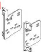
• A) Radio trim panel • B) Radio brackets • C) Pocket • D) Heated seat buttons (L & R) Blank panels • E) #8 x 3/8" Phillips screws (4) • F) Panel clips (6)
• G) HVAC interface and wiring harness (not shown) • H) Antenna adapter (not shown)
A B



natural_image
Illustration of various electronic component packages and screws (no text or symbols)TOOLS REQUIRED
- Panel removal tool
- Phillips screwdriver
- 9/32" Socket wrench - Cutting tool
E


TABLE OF CONTENTS
Dash Disassembly 2-3
Kit Preparation....4
Kit Assembly
- ISO DIN radio provision with pocket.....5
- ISO DDIN radio provision ....5
Axxess Interface Installation 6-10
Final Assembly....11
Configuration....12-14
WIRING & ANTENNA CONNECTIONS
Wiring Harness: Axxess interface built into kit Antenna Adapter: Included with kit USB Replacement Hubs: #AXFD-USB or
AXFD-USB2 (sold separately)
ATTENTION: With the key out of the ignition, disconnect the negative battery terminal before installing this product. Ensure that all installation connections, especially the air bag indicator lights, are plugged in before reconnecting the battery or cycling the ignition to test this product. NOTE: Refer also to the instructions included with the aftermarket radio.
DASH DISASSEMBLY
1. For vehicles with a center channel
speaker: Undip and remove the speaker grille in the center of the dash above the radio/climate control panel, and then remove the (2) 9/32" screws exposed. (Figure A)
2. For vehicles without a center channel
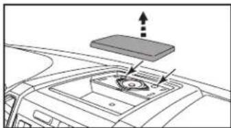
speaker: Remove the rubber pad in the shallow pocket above the radio/climate control panel, and then remove the (2) 9/32" screws exposed. (Figure B)
- Unclip and remove the panel above the radio/climate control panel, and then remove the (2) 9/32" screws from the top of the radio/climate control panel. (Figure C)
natural_image
Diagram of a car interior with a mounted device and directional arrows indicating movement (no text or symbols)(Figure A)

natural_image
Diagram of a device mounted on a car's front panel, showing a screen and battery (no text or symbols)(Figure B)

natural_image
Diagram of a car interior showing a rectangular tray mounted on the roof, with directional arrows indicating movement or force (no text or symbols present)(Figure C)
Ensure that the vehicle is completely off before proceeding onto the following (5) steps
- Using the panel removal tool, carefully unclip, unplug, and remove the radio/climate control panel.
- Remove the 9/32" Phillips screws securing the display screen:
(4) for the 4.2-inch display screen models,
(6) for 8-inch display screen models, then unplug and remove the screen. (Figure D)
Continued on the next page

natural_image
Interior view of a car dashboard with visible air vent and internal components (no text or symbols)(Figure D)
DASH DISASSEMBLY (CONT.)
-
For models with a 4.2-inch display screen and SYNC®: Remove (2) 9/32" screws securing the SYNC® module, then unplug and remove. (Figure F)
-
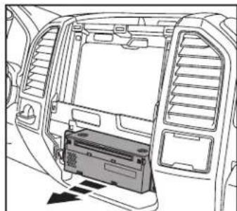
Remove (4) 9/32" screws securing the radio chassis, disconnect the wiring, and then remove the factory radio. (Figure G)

natural_image
Interior view of a car showing the rear air vent with internal components and a highlighted drive (no text or symbols visible)(Figure F)
- For models equipped with a factory backup camera: Remove the (2) 10mm nuts located at the top of the camera module. Loosen the bottom nut and reposition the module down onto the lower stud, then re-secure using just (1) 10mm nut. (Figure H)
Continue to Kit Preparation

natural_image
Interior view of a car showing the backrest door, vent, and internal battery pack (no text or symbols visible)(Figure G)

natural_image
Technical diagram of a vehicle engine compartment showing internal components and airflow path (no text or labels)(Figure H)
KIT PREPARATION
From the factory radio/climate control panel:
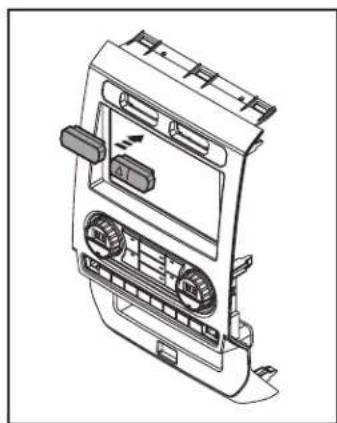
- Unclip and remove the hazard switch and traction control buttons.
To the 99-5849CH radio trim panel:
- Snap in the hazard switch and traction control buttons. (Figure A)
- Attach the (6) panel clips provided with this kit. (Figure B)
- For models with heated seats: Clip in the heated seat buttons. (Figure C)
For models without heated seats: Clip in the blank panels. (Figure C)
natural_image
Technical line drawing of a car air intake cabinet with ventilation slots and control panel (no text or labels)
(Figure B)(Figure A) (Figure C)

natural_image
Line drawing of a car air conditioner unit with labeled connectors (no text or symbols)Continue to Kit Assembly
KIT ASSE MB LY
ISO DIN radio provision with pocket
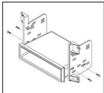
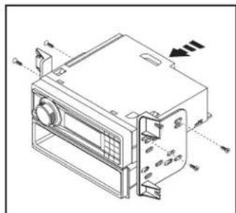
- Attach the pocket to the radio brackets using (4) Phillips screws provided with this kit. (Figure A)
- Remove the metal DIN sleeve and trim ring from the aftermarket radio.
- Slide the aftermarket radio into the radio bracket/pocket assembly, and then secure it using screws supplied with the radio. (Figure B)
- Reconnect the negative battery terminal and prepare for the Axxess interface installation.
natural_image
Technical line drawing of a mechanical housing or enclosure with mounting brackets and internal components (no text or symbols)(Figure A)
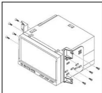
ISO DDIN radio provision
- Attach the radio brackets to the aftermarket radio using screws supplied with the radio. (Figure A)
- Reconnect the negative battery terminal and prepare for the Axxess interface installation.
Continue to Axxess Interface Installation
natural_image
Technical line drawing of an electronic device with ports and connectors (no text or symbols)(Figure A)
natural_image
Technical line drawing of a mechanical device with no visible text or symbols(Figure B)
AXXESS INTERFACE INSTALLATION
INTERFACE FEATURES
- Provides accessory power (12-volt 10-amp)
• Retains R.A.P. (Retained Accessory Power) - Provides NAV outputs (parking brake, reverse, speed sense)
- Retains audio controls on the steering wheel
- Allows the override of the STOP/START engine feature
- The factory STOP/START button can resume the STOP/START feature
- Retains the factory backup camera
- Can be used in both amplified and non-amplified models (including Sony)
Note: Factory B&O amplified sound systems require and additional interface sold separately. Part #AXA2B-FD1
• Retains balance and fade (excluding Sony)
- Micro-B USB updatable
INTERFACE COMPONENTS
- Axxess interface (built into kit)
• Car side harness (LD-TSCREEN-FD3) - HVAC interface
• HVAC interface harness (LD-FDHVAC)
• 4-pin flat to 4-pin stacked harness (packaged with the HVAC harness)
• 16-pin harness with stripped leads (LD-2NAVAMPL)
• 14-pin harness with stripped leads and a two-pin plug (LD-FD-AUX)
- 54-pin backup camera harness with a two pin plug (LD-FD54CAM)
• 12-pin backup camera harness
• Female 3.5 mm connector with stripped leads (LD-SWC-F3.5)
TABLE OF CONTENTS
Connections
For models without a Sony or B&O amplifier....7
For models with a Sony amplifier 8
3.5mm jack - steering wheel control retention....9
Backup camera harness....9
Installation....10
Final Assembly....11
Configuration Menu 12-14
TOOLS REQUIRED
- Crimping tool and connectors, or solder gun, solder, and heat shrink
- Tape • Wire cutter • Zip ties
Attention! This interface will work with models that are either Sony amplified, or non-amplified. Please follow the instructions carefully for your model vehicle. Failure to do so will result in either no sound, or low sound. If you are unsure if your vehicle is factory amplified or not, please contact your local dealership.
CONNECTIONS
For models without a Sony or B&O amplifier:
From the 16-pin harness with stripped leads to the aftermarket radio, connect as indicated:
• Red wire to the accessory wire.
- Orange/White wire to the illumination wire. (if applicable)
- Gray wire to the right front (+) speaker output.
- Gray/Black wire to the right front (-) speaker output.
- White wire to the left front (+) speaker output.
- White/Black wire to the left front (-) speaker output.
- Blue/White wire to the amp turn on wire' (if equipped with a factory subwoofer)
The following (3) wires are only for multimedia/navigation radios that require these wires.
• Blue/Pink wire to the VSS/speed sense wire.
• Green/Purple wire to the reverse wire.
• Light Green wire to the parking brake wire.
Tape off and disregard the following (5) wires, they will not be used in this application:
Brown, Green, Green/Black, Purple, Purple/Black
From the CAR SIDE HARNESS to the aftermarket radio, connect as indicated:
- Black wire to the ground wire.
- Yellow wire to the battery wire.
- Green wire to the left rear (+) speaker output.
• Green/Black wire to the left rear (-) speaker output. - Purple wire to the right rear (+) speaker output.
• Purple/Black wire to the right rear (-) output.
Tape off and disregard the following (1) wire, it will not be used in this application: Blue
AUX-in connections:
- Connect the Red and White RCA jacks labeled "FROM 3.5" to the audio AUX-IN jacks from the aftermarket radio.
- Disregard the Red and White RCA jacks labeled "RSE/SYNC ^ /SAT", they will not be used in this application.
Continue to 3.5mm Jack - Steering Wheel Control Retention
CONNECTIONS (CONT.)
For models with a Sony amplifier:
From the 16-pin harness with stripped leads to the aftermarket radio, connect as indicated:
• Red wire to the accessory wire.
• Blue/White wire to the amp turn on wire.
Note: This wire must be connected to hear sound from the factory amplifier.
- Orange/White wire to the illumination wire. (if applicable)
- Gray wire to the right front (+) speaker output.
- Gray/Black wire to the right front (-) speaker output.
- White wire to the left front (+) speaker output.
- White/Black wire to the left front (-) speaker output.
• Green wire to the left rear (+) speaker output.
• Green/Black wire to the left rear (-) speaker output.
• Purple wire to the right rear (+) speaker output.
• Purple/Black wire to the right rear (-) output.
Tape off and disregard the following (1) wire, it will not be used in this application: Brown
The following (3) wires are only for multimedia/navigation radios that require these wires.
• Blue/Pink wire to the VSS/speed sense wire.
• Green/Purple wire to the reverse wire.
• Light Green wire to the parking brake wire
From the CAR SIDE HARNESS to the aftermarket radio:
- Connect the Black wire to the ground wire.
- Connect the Yellow wire to the battery wire.
- Tape off and disregard the following (5) wires, they will not be used in this application: Blue, Green, Green/Black, Purple, Purple/Black
- Disregard the Red and White RCA jacks labeled "RSE/SYNC ^* /SAT", they will not be used in this application.
- Disregard the Red and White RCA jacks labeled "FROM 3.5", they will not be used in this application.
Continue to 3.5mm jack - steering wheel control retention
CONNECTIONS (CONT.)
3.5mm Jack - Steering Wheel Control Retention:
- The 3.5mm jack is to be used to retain audio controls on the steering wheel control.
For the radios listed below:
Connect the female 3.5mm connector with stripped leads, to the male 3.5mm SWC jack from the 5849 harness. Tape off and disregard remaining wires.
- Eclipse: Connect the SWC wire, Brown to the Brown/White wire of the connector. Then connect the remaining SWC wire, Brown/White to the Brown wire of the connector.
• Metra OE: Connect the Gray steering wheel control wire (Key 1) to the Brown wire. - Kenwood or select JVC with an SWC wire: Connect the Blue/Yellow wire to the Brown wire. Note: If the Kenwood radio auto detects as a JVC, manually set the radio type to Kenwood. See the instructions under Changing Radio Type.
- XITE: Connect the SWC (SWC-2) wire from the radio to the Brown wire.
- Parrot Asteroid Smart or Tablet: Connect the 3.5mm jack into the AXSWCH-PAR (sold separately), and then connect the 4-pin connector from the AXSWCH-PAR into the radio. Note: The radio must be updated to rev. 2.1.4 or higher software.
- Universal "2 or 3 wire" radio: Connect the SWC wire, (Key-A or SWC-1) to the Brown wire of the connector. Then connect the remaining SWC wire, (Key-B or SWC-2) to the Brown/White wire of the connector. If the radio comes with a third wire for ground, disregard this wire. Note: After the interface has been programmed to the vehicle, refer to the manual provided with the radio for assigning the SWC buttons. Contact the radio manufacturer for more information.
- For all other radios: Connect the 3.5mm jack from the AXSWC harness into the port on the aftermarket radio designated for an external SWC interface. Refer to the manual provided with the radio, if in doubt as to where the 3.5mm jack should connect.
OE Backup Camera Retention:
- Connect one side of the supplied camera retention harness to the 54 pin connector in the vehicle. This connector was removed from the factory 8" screen.
- Connect the two pin plug to the 14-pin AUX plug (LD-FD-AUX)
- Connect the Yellow RCA jack to the backup camera input from the aftermarket radio.
From the 14-pin harness with stripped leads to the aftermarket radio:
Step 1: Connect the two pin plug to the mating two pin plug on the camera harness (LD-FD54CAM)
The following wire is for triggering a relay from the buttons on the face of the radio trim panel. The outputs are latching, which means they will stay active until the button is pressed again (or until the ignition key has been turned off). These buttons can be used to turn on items such as: accent lighting or fans to cool aftermarket amplifiers.
- Connect the Blue/Red wire labeled "AUX 1" to the negative input from an automotive SPDT relay (sold separately).
- Connect the Blue/Black wire labeled "AUX 2" to the negative input from an automotive SPDT relay (sold separately).
INSTALLATION
Climate control panel
- Connect the 16-pin harness with stripped leads into port A.
- Connect the 14-pin harness with stripped leads into port B.
- Connect the FD3 HARNESS into port C, and then to the wiring harnesses in the vehicle. These harnesses are the ones removed in Dash Disassembly, step 7.
- Port D is a Micro-B USB input for updating the Axxess interface.

HVAC interface
- Connect the HVAC interface harness into the HVAC interface, and then to the wiring harnesses in the vehicle. These harnesses are the ones removed in Dash Disassembly, step 4.
Attention! Disregard the 10-pin connector from the HVAC interface harness, it will not be used in this application. - Connect the 4-pin flat to 4-pin stacked harness into the HVAC interface, and then to the passenger airbag light assembly.
- Connect the 6-pin harness from the car side harness to the HVAC interface.
- For models with a 4.2-inch display screen: Connect the 12-pin backup camera harness to the wiring harness in the vehicle. This harness is the one removed in Dash Disassembly, step 5.
For models with an 8-inch display screen: Connect the female connector from the 54-pin backup camera harness to the wiring harness in the vehicle. This connector is located behind the factory display screen, which was removed in Dash Disassembly, step 5. Note: Disregard the male connector, it will not be used in this application. - Locate the factory antenna connector in the dash and complete all necessary connections to the radio. Use the antenna adapter provided to adapt the factory antenna connector to the aftermarket radio.
INSTALLATION cont.
- Open the driver's door, and keep open during the programming process.
- Cycle the ignition on and wait until the climate control lights turn blue.
Note: If the lights don't turn blue, unplug Port C from the tactile panel for several seconds, then try again.
- Test all functions of the installation for proper operation, before reassembling the dash.
FINAL ASSEMBLY
- Secure the completed assembly into the upper dash using the factory hardware removed in Dash Disassembly, step 5.
- Snap the radio trim panel over the completed assembly, then reassemble the dash in reverse order of disassembly to complete the installation.
CONFIGURATION MENU
The buttons on the steering wheel will be used to enter, navigate, and make changes to the menu. The display on the climate knobs will be used to view the menu.
- With the driver's door open, press and hold the Mode/OK button, then cycle the key on.
- Press the Seek buttons to toggle through the menu options available. Refer to the Menu Options table for a list of options, and description of each option.
- Press the Volume buttons to toggle through the sub-menu options available. Refer to the appropriate Sub-Menu Options table for the item in interest.
- Once an item has been chosen to change, press the Mode/OK button.
- Navigate to "d o", then press the Mode/OK button to exit the Configuration Menu.
- If no activity after (10) seconds the Configuration Menu will close.
Menu Options
| Left Knob Display Right Knob | Display Description | ||
| A.L Ambient Lighting | Will display current state | ||
| A.G OEM Amplifier Gain | |||
| A.S. | Auto Stop/Start Override | ||
| r.d | Radio Detection | ||
| b.L. | Backlight | ||
| U O Version Number of Kit | |||
| d o | n E | Done/Quit | |
Sub-Menu Options
Ambient Lighting
| Left Knob Display | Right Knob Display | Ambient lighting Color |
| A.L | Ib | Ice Blue |
| A.L | Or | Orange |
| A.L | Sb | Soft Blue |
| A.L | rd | Red |
| A.L | Gr | Green |
| A.L | bL | Blue |
| A.L | PU | Purple |
OEM Amplifier Gain
| Left Knob Display | Right Knob Display |
| A.G | 0 to 30 |
Auto Stop/Start Override
| Left Knob Display | Right Knob Display | |
| A.S | 0.0 | Disabled (no over-ride) |
| A.S | 0.1 | Enabled |
CONFIGURATION MENU (CONT.)
Sub-Menu Options (cont.)
- Press the Mode button on the steering wheel to start the auto detection process.
Radio Detection
| Left Knob Display Right Knob Display Radio Manufacturer Keynotes | |||
| r.d 1 Eclipse (Type 1) | 1 | ||
| r.d | 2 | Kenwood | 2 |
| r.d 3 | Clarion (Type 1) 1 | ||
| r.d 4 Boss (type 1)/Dual/Sony | 1 (Boss) | ||
| r.d | 5 | JVC | |
| r.d | 6 | Pioneer/Jensen | |
| r.d | 7 | Alpine | 3 |
| r.d 8 Boss (type 4)/Visteon 1 (Boss) | |||
| r.d | 9 | Valor | |
| r.d | 10 Clarion (Type 2) | ||
| r.d | 11 Boss (Type 2) | ||
| r.d | 12 Eclipse (Type 2) | ||
| r.d | 13 | LG | |
Radio Detection (cont.)
| Left Knob Display Right Knob Display Radio Manufacturer Keynote | |||
| r.d | 14 | Parrot | 4 |
| r.d | 15 | XITE | |
| r.d | 16 | Philips | |
| r.d | 17 | Kicker | |
| r.d | 18 | JBL | |
| r.d | 19 | Insane Audio | |
| r.d | 20 | Magnadyne | |
| r.d | 21 | Boss (type 3) | |
| r.d | 22 | Axxera | |
- If the steering wheel controls don't work, change the radio type to the opposite radio type.
- If the display shows 5 (JVC), change the radio type to 2 (Kenwood).
- If the display shows Alpine, but an Alpine radio isn't installed, make sure the 3.5mm jack is plugged in.
- AXSWCH-PAR required (sold separately). The software in the radio must be rev. 2.1.4 or higher.
CONFIGURATION MENU (CONT.)
Sub-Menu Options (cont.)
Backlight
| Left Knob Display Right Knob Display Backlight Color | ||
| b.L -- No backlight | ||
| b.L | rD | Red |
| b.L | Or | Orange |
| b.L | YE | Yellow |
| b.L LG Lime Green | ||
| b.L | Gr | Green |
| b.L | CY | Cyan |
| b.L | BL | Blue |
| b.L | Pu | Purple |
| b.L | HP Hot Pink | |
Version Number of Kit
| Left Knob Display | Right Knob Display |
| UO | Will display current version of kit |
Done/Quit
- Press the Mode/OK button on the steering wheel to exit the Configuration Menu.
| Left Knob Display | Right Knob Display |
| do | n E |
Having difficulties? We're here to help.
Contact our Tech Support line at:
386-257-1187
Or via email at:
techsupport@metra-autosound.com
Tech Support Hours (Eastern Standard Time)
Monday - Friday: 9:00 AM - 7:00 PM
Saturday: 10:00 AM - 5:00 PM
Sunday: 10:00 AM - 4:00 PM

KNOWLEDGE IS POWER
Enhance your installation and fabrication skills by swelling in the most recognized and respected
mobile electronics school in our industry.
Log onto www.installerinstitute.com or call
600-554-0182 for more information and take steps toward a better tomorrow.

Metra recommends MECP certified technicians

natural_image
Interior view of a car dashboard with digital displays and air filters (no visible text or symbols)Ford F-150\* 2015-2020 Ford F250/350/450 XL (w/CD)\*, XLT\* 2017-2019 \* Con dimatizador manual
natural_image
Diagram of a car interior showing a mounted device with arrows indicating direction (no text or symbols)(Figura A)

natural_image
Diagram of a device mounted on a car's front panel, showing a screen and battery (no text or symbols)(Figura B)

natural_image
Diagram of a car interior showing a square tray mounted on the roof, with directional arrows indicating movement or force (no text or symbols present)(Figura C)
natural_image
Technical line drawing of a car interior showing internal components and a highlighted device (no text or symbols)(Figura D)
DESMONTAJE DEL TABLERO (CONT.)
natural_image
Interior view of a car showing the dashboard and air vent (no text or symbols visible)(Figura F)
natural_image
Technical line drawing of a car interior showing engine compartment and steering wheel (no text or symbols)(Figura H)
natural_image
Interior view of a car showing the backrest door, air vent, and internal battery compartment (no text or symbols visible)(Figura G)
PREPARACIÓN DEL KIT
Del panel del radio/control del clima de fábrica:
natural_image
Technical line drawing of a car air intake cabinet with ventilation slots and control panel (no text or labels)
(Figura B)(Figura A) (Figura C)

natural_image
Line drawing of a car air conditioner unit with labeled connectors (no text or symbols)natural_image
Technical line drawing of a mechanical housing or enclosure with mounting brackets and internal components (no text or symbols)(Figura A) (Figura A)
natural_image
Technical line drawing of an electronic device with ports and wiring (no text or symbols)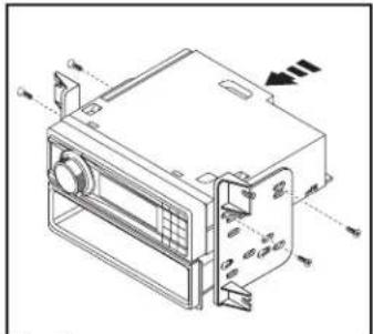
(Figura B)
Monday - Friday: 9:00 AM - 7:00 PM
Saturday: 10:00 AM - 7:00 PM
Sunday: 10:00 AM - 4:00 PM

EL CONOCIMIENTO ES PODER
Móvil (Mobile Electronics
Certification Program, MECP).



- Ford F150 2015-2020\*
- F250/350/450/550 XL 2020-2022\*
- KIT FEATURES
- KIT COMPONENTS
- TOOLS REQUIRED
- TABLE OF CONTENTS
- WIRING & ANTENNA CONNECTIONS
- AXFD-USB2 (sold separately)
- DASH DISASSEMBLY
- For vehicles with a center channel
- For vehicles without a center channel
- Ensure that the vehicle is completely off before proceeding onto the following (5) steps
- DASH DISASSEMBLY (CONT.)
- KIT PREPARATION
- From the factory radio/climate control panel:
- To the 99-5849CH radio trim panel:
- KIT ASSE MB LY
- ISO DIN radio provision with pocket
- ISO DDIN radio provision
- AXXESS INTERFACE INSTALLATION
- INTERFACE FEATURES
- INTERFACE COMPONENTS
- CONNECTIONS
- For models without a Sony or B&O amplifier:
- From the 16-pin harness with stripped leads to the aftermarket radio, connect as indicated:
- From the CAR SIDE HARNESS to the aftermarket radio, connect as indicated:
- AUX-in connections:
- CONNECTIONS (CONT.)
- For models with a Sony amplifier:
- From the CAR SIDE HARNESS to the aftermarket radio:
- 3.5mm Jack - Steering Wheel Control Retention:
- For the radios listed below:
- OE Backup Camera Retention:
- From the 14-pin harness with stripped leads to the aftermarket radio:
- INSTALLATION
- Climate control panel
- HVAC interface
- INSTALLATION cont.
- FINAL ASSEMBLY
- CONFIGURATION MENU
- CONFIGURATION MENU (CONT.)
- Sub-Menu Options (cont.)
- Done/Quit
- Ford F-150\* 2015-2020 Ford F250/350/450 XL (w/CD)\*, XLT\* 2017-2019 \* Con dimatizador manual
- DESMONTAJE DEL TABLERO (CONT.)
- PREPARACIÓN DEL KIT
- Del panel del radio/control del clima de fábrica:
Brand : Axxess
Model : 99-5849CH
Category : Car kit