
EN4216MR - Receiver Inovonics - Free user manual and instructions
Find the device manual for free EN4216MR Inovonics in PDF.


| Product Type | 16 Zone Multi-Condition Receiver with Relay Outputs |
| Brand | Inovonics |
| Model | EN4216MR |
| Dimensions | 165 mm x 89 mm x 25 mm (6.5" x 3.5" x 1") |
| Weight | 280 g (0.62 lb) |
| Operating Environment | 0° to 60°C (32° to 140°F), 90% relative humidity (non-condensing) |
| Power Requirement | 11–14 VDC, 400 mA |
| Output Specifications | Form C relay, 1A @ 28 VDC / 0.5A @ 30 VAC resistive load |
| Receiver Type | Frequency hopping spread spectrum |
| Operating Frequency Bands | 902–928 MHz (North America), 915–928 MHz (Australia), 921–928 MHz (New Zealand) |
| Number of Points/Transmitters | 16 |
| Number of Relay Outputs | 6 (Form C) |
| Event Log Capacity | 50 events (FIFO) |
| Tamper Protection | Type B, fixed device; housing tamper included |
| UL Listings | UL 365, UL 636, UL 985, UL 1023, ULC/ORD-C1023-74, UL 1610, UL 1076 |
| Included Accessories | Two drywall anchors, two mounting screws, two pieces double-sided tape, one selection jumper |
| Display | LCD display with navigation buttons |
| Installation Distance from Control Unit | Within 30 m (98.5 ft) |
Frequently Asked Questions - EN4216MR Inovonics
User questions about EN4216MR Inovonics
0 question about this device. Answer the ones you know or ask your own.
Ask a new question about this device
Download the instructions for your Receiver in PDF format for free! Find your manual EN4216MR - Inovonics and take your electronic device back in hand. On this page are published all the documents necessary for the use of your device. EN4216MR by Inovonics.
USER MANUAL EN4216MR Inovonics
EN4216MR 16 Zone Multi-Condition Receiver with Relay Outputs
Installation and Operation Manual
1 Overview
The EN4216MR receiver allows you to add up to 16 transmitters and five outputs to any application, and includes a housing tamper for increased tamper security.
The following add-on receivers are available from Inovonics:
| Receiver | Alarm Output Relays | Fault Relays | Transmitters Supported |
| EN4204R | 4 1 | 4 | |
| EN4216MR 5 1* 16 | |||
| EN4232MR 11 1* 32 |
* At least one relay must be used for faults to ensure the system is supervised. More than one relay may be used, but that will deduct from the number of alarm output relays.
1.1 Installing an Inovonics Security System
An EchoStream survey kit must be used to establish a UL system. The EchoStream survey kit measures the signal strength of high-power repeater and sensor messages to help optimize your EchoStream system.

flowchart
graph TD
    subgraph Cloud
        A["Transmitter"] --> B["Repeater"]
        B --> C["Receiver"]
        C --> D["Cloud Node 1"]
        C --> E["Cloud Node 2"]
        C --> F["Cloud Node 3"]
        C --> G["Cloud Node 4"]
        C --> H["Cloud Node 5"]
        C --> I["Cloud Node 6"]
        C --> J["Cloud Node 7"]
        C --> K["Cloud Node 8"]
        C --> L["Cloud Node 9"]
        C --> M["Cloud Node 10"]
    end
    A --> B --> C --> D --> E --> F --> G --> H --> I --> J --> K --> L --> M
    style Cloud fill:#f9f,stroke:#333
    style Transmitter fill:#ccf,stroke:#333
    style Repeater fill:#cfc,stroke:#333
    style Receiver fill:#fcc,stroke:#333
    style Receiver fill:#fcc,stroke:#333
    style Receiver fill:#fcc,stroke:#333
    style Receiver fill:#fcc,stroke:#333
    style Receiver fill:#fcc,stroke:#333
    style Receiver fill:#fcc,stroke:#333
    style Receiver fill:#fcc,stroke:#333
    style Receiver fill:#fcc,stroke:#333
    subgraph Cloud
        A --> B --> C --> D --> E --> F --> G --> H --> I --> J --> K --> L --> M
    end
Figure 1 Sample EchoStream system
The EchoStream survey kit provides you with two signal strength measurements: signal level and signal margin.
Signal level
The signal level is the measurement of the overall decibel level of the message.
Signal margin
The signal margin is the measurement of the decibel level of the message, minus the decibel level of any interfering signals. Inovonics Wireless equipment should be placed within a facility such that all end-devices produce signal margin readings of at least 4 decibels.
Both the signal level and signal margin are measured in decibels. Because signal strength and signal margin are measured on a logarithmic scale, the difference between a decibel level of 3 (Weak) and a decibel level of 4 (Good) is a much larger difference than it would be on a linear scale.
Note: For more information about the EchoStream survey kit, see the EN7017 Survey Kit and App Installation and Site Survey Instructions.
Caution: The EchoStream system should be tested regularly to ensure operation. To test: place the system in test mode, activate an end device, and ensure an appropriate response.
1.2 RF Signal Propagation
While wood, drywall and glass usually let the RF signals pass, some materials may inhibit or attenuate radio frequency (RF) signal propagation by blocking, reflecting, deflecting or absorbing RF signals.
Consider anything between transmitters and repeaters and/or the receiver. Is there concrete and steel construction? Are there earthen berms or hills? Are there a lot of trees? Devices should be mounted such that they are least affected by these elements.
For best results, transmitters and repeaters should be mounted at the optimal height to achieve line of sight to repeaters and/or the receiver. Usually this means they will be mounted as high as possible.
Following are some typical obstacles to RF signal propagation:
| Material Affect Recommendation | ||
| Metal construction, including ductwork; pipes; studs; stucco, plaster or concrete with wire mesh; satellite dishes, metal-lined rooms such as walk-in coolers or freezers; metal siding, safes, etc. | Can reflect, absorb and/or disrupt RF signals. | Perform a site survey using an Inovonics wireless survey kit to verify the RF signal is acceptable, and, when necessary, to determine where to locate repeaters. |
| Completely enclosed metal boxes/enclosures. | Can restrict RF signals. | |
| Solar panels, cinder block walls, windows with built-in solar tinting. | Can absorb and/or reflect RF signals. | |
| Vegetation. Can attenuate | RF signals. The RF environment can alter as trees shed or sprout leaves. | Add repeaters as issues arise. |
| Automobile and truck traffic. | Can disrupt RF signals. | Mount Inovonics devices at a height sufficient to achieve line of sight above traffic. |
1.3 Inovonics Contact Information

For product and installation videos visit us at www.inovonics.com/videos or use the QR code below.

If you have any problems with this procedure, contact Inovonics technical services:
• E-mail: support@inovonics.com.
• Phone: (800) 782-2709; (303) 939-9336.
1.4 EN4216MR Front Panel

Figure 2 Receiver front panel
A Output LED
B Fault LED
C Power LED
D LCD display
E Up button
F Down button
G Back button H Enter button
Output LED: Lights when any transmitter output is active.
Fault LED: Lights when any transmitter is sending a fault condition.
Power LED: Lit when receiving power.
LCD Display: Shows status, event log and programming information.
Decode LED: Flashes when any recognizable transmission is received.
This LED is only visible when the cover is removed.
Up button: Scrolls the display up.
Down button: Scrolls the display down.
Back button: Returns display to the previous menu, or when pressed in the main menu options, returns the unit to normal operating mode. When
entering information in the display, returns to the last character entered.
Enter button: Selects the currently displayed menu item. If in normal operating mode, sets the unit to menu mode.
Reset button: Clears the current status for all points and resets all outputs and LEDs. Records a receiver reset entry in the event log and resets the supervision window timers. This button is only accessible when the cover is removed.
1.5 EN4216MR Internal Components

Figure 3 EN4216MR internal components
A Housing release tabs
B Power connections
C Operation LEDs
D Relay outputs
E Tamper output
F Receiver power loss output
G Jam output
H Reset input
I Frequency band selection pins
J Reset button
K Decode LED
1.6 What's in the Carton
- Two drywall anchors.
- Two mounting screws
- Two pieces of double-sided mounting tape.
• One selection jumper.
2 Installation and Startup
2.1 Installation Notes
• These products are designed to be maintained by professional security technicians.
- Products are tested for indoor use.
- Do not mount wireless smoke detectors, co detectors, initiating device transmitters or repeaters to removable surfaces, such as ceiling tiles.
- All products should be manually tested weekly.
- The EN4216MR must be installed within 30 m (98.5 ft) of control unit.
- Low power transmitters shall be limited to a single initiating device.
2.2 Power Cabling
Caution: Incorrect connections may cause damage to the unit.
Before beginning startup, you will need to connect power to the receiver. To connect power to the receiver:
- Use a small screwdriver to press the housing release tabs on the top or bottom of the receiver; separate the housing.
- Connect power cabling to the Vs (+) and GND (-) connections.
- Power source should be 11-14 VDC. Power supply must be unswitched, uninterrupted, and regulated.
- Use 18 - 22 gauge wire for all cabling, and ensure torque on the screw terminals does not exceed 7 inch-pounds.
2.3 Select the Frequency Band
EchoStream products are able to use a range of radio frequencies, and are shipped from Inovonics set for your geographic area.
- The jumper will be set on the two pins marked NZ to set the frequency range to 921-928 MHz for New Zealand.
- The jumper will be set on the two pins marked AU to set the frequency range to 915-928 MHz for Australia.
-
The jumper will be removed to set the frequency band to 902-928 MHz for North America.
-
Ensure the frequency band is set for your geographic are.
-
If the frequency band is not set for your geographic area, place a selection jumper on the appropriate frequency band selection pins to select Australia or New Zealand, or remove it for North America.
Note: Only devices set for use in North America are configured for UL installations.
- If you have changed the frequency band and the device is powered on, press the reset button to complete configuration.
2.4 Connect Input/Output Cabling
- Connect cabling to the receiver power loss output. Must be configured for UL installations.
- The receiver power loss output is a normally closed (N/C) open collector output that opens when the receiver loses power.
- Connect cabling to the tamper output. Must be configured for UL installations.
- The tamper output is a normally open (N/O) open collector output that reports receiver case tamper to an external device.
- Connect cabling to the jam output. Must be configured for UL installations.
- The jam output is a normally closed (N/C) open collector output that opens when noise thresholds on all receive channels remain above a predetermined value for 10 seconds. The jam output is set to the follower output type.
- Connect a momentary switch to the reset input and ground (Figure 4, "EN4216MR terminals"). Must be configured for UL installations.
- The reset input circuit permits installation of a remote momentary normally open (N/O) switch to clear faults, unlatch outputs, and reset the receiver to a normal state.
- Connect cabling to the output terminals. Must be configured for UL installations.
• The EN4216MR provides six Form-C relays.
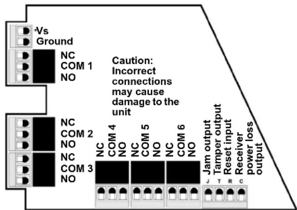
Figure 4 EN4216MR terminals
2.5 Mount the Receiver
Caution: Mount the receiver in a location removed from metal. Metal objects (duct work, wire mesh screens, boxes) will reduce RF range.
Note: For UL listed systems containing a UL hold-up switch, the EN4216MR must be located within three feet of a system keypad in a location out of sight from the protected premise.
-
Use the provided anchors and screws to mount the receiver in a location accessible for future maintenance.
-
Perform a walk test, activating each transmitter assigned to the receiver and ensuring a good signal.
3 Point Setup and Registration
Each transmitter must setup and registered to a point. Once registered, the transmitters alarm(s) will be mapped to the appropriate alarm output(s). Following are the transmitters supported by the EN4216MR:
Note: Contact Inovonics for a list of other compatible devices..
Table 1: EN4216MR Supported Transmitters
| Transmitter Alarm 1 Alarm 2 Alarm 3 Alarm 4 | ||||
| EN1215EOL Terminal block | ||||
| EN1215WEOL Terminal block | Reed switch | |||
| EN1223D Both buttons | ||||
| EN1235SF Button | ||||
| EN1235DF Both buttons | ||||
| EN1244 Smoke | ||||
| EN1245 CO | ||||
| EN1249 Bill trap | ||||
| EN1261HT Motion | ||||
Table 2: Default Trouble Condition Programming
| Output/Relay | Condition |
| 6 | Tamper |
| 6 | Low Battery |
| 6 | Supervision Loss/Inactive |
| See Figure 4, “EN4216MR terminals” on page 2. | Line Power Loss |
3.1 Program a Point
- From the EN4216MR start screen, press the enter button to access the receiver's three main menu options.
- Use the up and down buttons to navigate to the install & service menu; press the enter button.
- Enter your password to access the install & service menus.
- Following the instructions in section 4.5.1, "Setup Point" on page 4.
4 EN4216MR 16 Zone Multi-Condition Receiver with Relay Outputs Operation and Point Setup Screens
4.1 Menu Tree
POINT STATUS, see 4.3, "Point Status" on page 3.
EVENT LOG, see 4.4, "Event Log" on page 3.
INSTALL & SERVICE, 4.5, "Install & Service" on page 4.
SETUP POINT, see 4.5.1, "Setup Point" on page 4.
POINT #
SUPERVISION TIME
SECURITY/REPEATER
ALARM INPUTS
ALARM OUT
ALARM OUTPUT TYPE
INACTIVE OUT/TYPE
TAMPER OUT/TYPE
LOW BATTERY OUT/TYPE
TEXT
REGISTER
REGISTER TRANSMITTER, see 4.5.2, "Register Transmitter" on page 4.
DELETE POINT, see 4.5.3, "Delete Point" on page 4.
SIGNAL STRENGTH, see 4.5.4, "Signal Strength" on page 5.
CHANGE PASSWORD, see 4.5.5, "Change Password" on page 5.
FACTORY CONFIG, see 4.5.6, "Factory Config" on page 5.
4.2 EN4216MR Start Screen
The EN4216MR start screen displays alarm and fault information on the LCD display. Points in alarm are displayed as "Alarm", with the point number following. If more than one point is in alarm, the display scrolls through each point. If a point has more than one alarm, the display scrolls through each alarm. Fault conditions are indicated by "Fault" in the LCD display if there is no alarm already displayed, and point numbers are not displayed.
Alarms and faults will only display briefly when the alarm or fault is first received, and then the start screen will return to a ready condition. For detailed alarm and fault information, see section 4.3, "Point Status" on page 3.
4.3 Point Status
The point status menu allows you to view detailed alarm and fault information. Point status information is available without entering a password.
To access the point status menu:
-
From the EN4216MR start screen, press the enter button to access the receiver's three main menus. "Point Status" displays.
-
Press the enter to display point status details.
-
Use the up/down buttons to scroll through the points; press the enter button again to view the outputs the displayed conditions are mapped to.
- Point status flags are defined as follows: A = Alarm (transmitter only); T = Tamper; B = Low Battery; L = AC loss (repeater only); I = Inactive.
Note: If "--" displays, the displayed condition has been mapped to a null output.
4.4 Event Log
The event log displays the last 50 events that have occurred, whether they be alarms, or tamper or inactive faults. Event log information is available without a password.
-
From the EN4216MR start screen, press enter.
-
Use the up or down buttons to navigate to "Event Log"; press the enter button.
-
Use the up/down buttons to scroll through events.
-
When viewing transmitter events, press enter to see the output the events map to.
Note: No output will be displayed if the event is mapped to a null output.
4.5 Install & Service
Note: The default password is 3446.
The install & service menu is used to reset factory configuration, change password, view signal strength, delete points, register transmitters, and setup points for any of the programmed points.
To access the install & service menu:
-
From the EN4216MR start screen, press the enter button to access the receiver's three main menu options.
-
Use the up and down buttons to navigate to the install & service menu; press the enter button.
-
Enter a password to access install & service menus.
4.5.1 Setup Point
- From the install & service menu, press enter at the "Setup Point" prompt.
- Use the up/down buttons to scroll through point numbers; press the enter button to select a point.
- “Tx Registr'd” displays if a transmitter or repeater is currently registered to this point; “Tx Not Registr'd” displays if no transmitter is registered to this point.
- Press enter to continue.
Supervision Time: Sets a time limit on missing transmitters.
- The valid range is 0 to 99 hours. The default is 60 minutes. Selecting 0 turns off supervision.
Caution: Turning off supervision can jeopardize the integrity of your system. Inovonics does not recommend turning off supervision. For supervision to function correctly, the supervision time must be set for an interval greater than the transmitter check-in time.
a. Use the up and down buttons to adjust the supervision time; press the enter button to select.
b. Use the up and down buttons to toggle between "Hrs" (hours) and "Min" (minutes); press the enter button to select.
Select Security/Repeater: Configures point's alarm and alert messages as either a repeater or a security transmitter.
a. Use the up and down buttons to choose "Select Security" for a transmitter or "Select Repeater" for a repeater; press the enter button to select.
1-4 Alarm Inputs: Allows security transmitters with multiple alarm conditions to be assigned a separate output and output type for each individual condition. For more information, see Table 1:, "EN4216MR
Supported Transmitters".
a. Use the up and down buttons to navigate the number of alarm inputs for the transmitter; press the enter to select.
Alarm Out: Maps the security transmitter's alarm condition(s) to relay outputs.
a. Use the up/down buttons to scroll through the output numbers. Choosing "--" will disable alarm output.
b. Press Enter to select the output to use for the alarm condition.
Alarm Output Type: Selects the output type for the alarm condition. The default is follower.
a. Use the up/down buttons to scroll through the output type options in Table 3; press the enter button to select the desired output option:
Table 3: Output Type Options
| Output Type Description | |
| Follower The output reflects the transmitter's alarm status. | |
| Latching The output turns on when activated and remains on until the receiver is reset. | |
| Toggle The output changes state each time the device sends a new activation. Press the enter button to select. "Inactive" displays when selected. Inactive time prevents output chatter. The valid range is 2.0 to 99.5 seconds, in 0.5 second increments. Use the up and down buttons to navigate. | |
| Momentary Momentary: The output turns on for the programmed duration, then turns off, regardless of the device status. Press the enter button to select. "Moment" displays when selected. This sets the time that the output will stay activated. The valid range 0.5 to 99.5 seconds, in 0.5 second increments. Use the up and down buttons to navigate. |
Inactive Out: Maps transmitter/repeater inactivity fault output.
a. Use the up/down buttons to scroll through the output numbers.
Choosing “--” will disable inactivity reporting.
b. Press enter to select the output to use for this transmitter/repeater.
Inactive Output Type: Selects the output type for the inactive condition. a. Use the up/down buttons to scroll through the output type options in Table 3; press the enter button to select the desired output option:
Tamper Out: Maps transmitter/repeater tamper fault output.
a. Use the up/down buttons to scroll through the output numbers. Choosing "--" will disable tamper output.
b. Press enter to select the output to use for this transmitter/repeater's tamper transmission.
Tamper Output Type: Selects the output type for the tamper condition. a. Use the up/down buttons to scroll through the output type options in Table 3; press the enter button to select the desired output option.
Low Batt Out: Maps transmitter/repeater low battery fault output.
a. Use the up/down buttons to scroll through the output numbers. Choosing “--” will disable low battery output.
b. Press enter to select the output to use for this transmitter/repeater's low battery transmission.
Low Battery Output Type: Selects the output type for the low battery condition.
a. Use the up/down buttons to scroll through the output type options in Table 3; press the enter button to select the desired output option:
Line Power Loss Out: Maps repeater line power loss fault output.
a. Use the up/down buttons to scroll through the output numbers. Choosing “--” will disable line power loss output.
b. Press enter to select the output to use for this repeater's line power loss transmission.
Line Power Loss Output Type: Selects the output type for the line power loss condition.
a. Use the up/down buttons to scroll through the output type options in Table 3; press the enter button to select the desired output option:
Text: Enter eight-character descriptive text for the transmitter/repeater a. Use up/down buttons to scroll through the alphanumeric characters; press enter to select and advance to the next character. To select a space, press enter without selecting a digit.
Note: If you do not use all eight characters, you must enter spaces to the end of the line.
b. When finished, press enter again to complete selection.
Register Transmitter: The register transmitter option allows you to register a transmitter or repeater to the programmed point.
a. Use the up and down buttons to toggle between "N" for no and "Y" for yes to choose whether or not you wish to register a transmitter/repeater to the point; press enter to select.
b. Press the transmitter/repeater's reset button at the "Reset Xmitter" prompt.
c. When "Tx Reg'd" displays, press enter to finish and advance to the next point.
d. When all transmitters have been registered, press reset on the receiver to clear faults.
Note: A transmitter/repeater can be registered to the point at a later time using the "Register Xmitter" prompt in the install & service menu.
4.5.2 Register Transmitter
The register xmitter option allows you to register a transmitter or repeater.
-
From the install & service menu, use the up and down buttons to navigate to the "Register Xmitter" prompt; press the enter button.
-
Use the up and down buttons to choose the point to which you want to register the transmitter/repeater.
-
Use the up and down buttons to toggle between "N" for no and "Y" for yes to choose whether or not you wish to register a transmitter/repeater to the point; press enter to select.
-
Press the transmitter/repeater's reset button at the "Reset Xmitter" prompt.
4.5.3 Delete Point
The DELETE POINT option allows you to delete transmitter registration information from all registered points, or from a specific point. Programmed point information is not deleted; just the registration identification number associated with the transmitters or repeaters. To delete points:
- From the install & service menu, use the up and down buttons to navigate to the "Delete Point" prompt; press the enter button.
- The "Delete All?" prompt displays. Use the up and down buttons to choose "N" for no or "Y" for yes; press enter to select.
- If you selected no, the "Delete Point" prompt displays. Use the up and down buttons to choose a point to delete; press enter to select.
- Press the enter button. If there is more than one registered point, then pressing the enter button returns to point selection for deletion; if there are no more registered points, the display returns to the install & service menu.
4.5.4 Signal Strength
The SIGNAL STRENGTH option is used to measure signal strength and troubleshoot installation problems.
- At the "Signal Strength" prompt, press enter.
- The first programmed point displays, along with a signal quality of good, weak or no sig.
Note: The point must have an active transmitter associated with it to display signal strength.
- Use the up/down buttons to scroll through the registered transmitters.
- Press enter to view level (LV) and margin (MA).
- Level indicates the overall signal strength; margin indicates the signal strength minus the background noise.
Note: Inovonics recommends a level of 10 for most installations.
4.5.5 Change Password
Passwords can be up to five digits long. The password is 3446. To change the password:
-
From the install & service menu, press enter at the "Change Password" prompt.
-
Use the up/down buttons to scroll through the digits; press enter to select and advance to the next digit.
Note: Choosing a null as the password will disable the function, allowing users to perform receiver functions and/or change parameters without a password.
-
When finished, press enter again to complete selection.
-
When "Password Changed" displays, press enter to return to the install & service menu.
Caution: Store the new password in a secure place. If the new password is lost, you will not be able to access the receiver without restoring it to factory defaults as described in "Factory Config" on page 5.
4.5.6 Factory Config
The factory config option is used to restore the EN4216MR to its factory defaults.
Caution: Choosing factory config will erase all programmed point and output information, as well as the password.
To restore the factory configuration defaults to the EN4216MR:
-
From the install & service menu, use the up and down buttons to navigate to the "Factory Config" prompt; press the enter button.
-
The "Reset Config" prompt displays. Use the up and down buttons to choose "Y" for yes; press enter to select.
-
The "Config Reset" prompt displays; press the enter button to return to the install & service menu.
The receiver can also be brought back to the factory default configuration through a hardware initiated sequence.
-
Connect a wire between the reset terminal and the ground terminal.
-
While pressing the back button, cycle the power to the unit.
-
Release the back button and remove the wire between the reset terminal and ground.
-
"Reset Config?" displays; select "Y" and press the enter button.
5 Specifications
UL compatible repeater, transmitters: EN5040-T, EN1215EOL, EN1215WEOL, EN1223D, EN1235SF, EN1235DF, EN1244, EN1245, EN1249, EN1261HT.
Dimensions: 165 mm x 89 mm x 25 mm (6.5" x 3.5" x 1"). Weight: 280 g (.62 lb).
Operating environment: 0°-60°C (32°-140°F), 90% relative humidity, non-condensing.
Power requirement: 11 - 14 VDC; 400 mA.
Output specifications: Form C relay 1A @ 28 VDC, 0.5 @ 30 VAC resistive load.
Input specifications: A low is less than .5 V; a high is greater than 2.5 V. Reset input: Contact closure, momentary low.
Receiver type: Frequency hopping spread spectrum.
Operating frequency: 915-928 MHz (Australia), 921-928 MHz (New Zealand), 902-928 MHz (USA).
Tamper: Type B, fixed device.
Number of points/Transmitters: 16.
Number of outputs: Six Form C relay outputs.
Event history log capacity: 50 events (first-in, first-out replacement).
UL listings: UL 365, UL 636, UL 985, UL 1023, ULC/ORD-C1023-74, UL 1610, UL 1076.
Note: Inovonics supports recycling and reuse whenever possible. Please recycle these parts using a certified electronics recycler.
flowchart
graph LR
    A["Tamper"] --> B["GND"]
    C["Reset"] --> D["GND"]
    E["Receiver Power Loss"] --> F["GND"]
    G["Jam"] --> H["GND"]
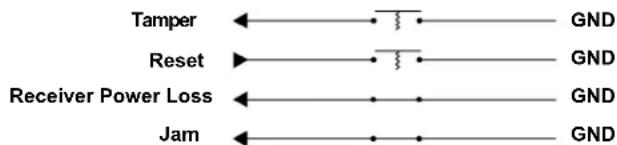
Figure 5 Tamper, reset, arm and receiver operational circuits
6 UL Requirements
- The control panel must be programmed to indicate an alarm if the system is in an armed condition and an RF jamming signal occurs at the receiver.
- The receiver tamper and transmitter tamper cannot be combined in one loop.
- The control unit providing input power to the receiver must not have a range outside of 11-14 VDC.
7 Television and Radio Interference
This equipment has been tested and found to comply with the limits for a Class B digital device, pursuant to Part 15 of the FCC Rules. These limits are designed to provide reasonable protection against harmful interference in a residential installation. This equipment generates, uses and can radiate radio frequency energy and, if not installed and used in accordance with the instructions, may cause harmful interference to radio communications. However, there is no guarantee that interference will not occur in a particular installation. If this equipment does cause harmful interference to radio or television reception, which can be determined by turning the equipment off and on, the user is encouraged to try to correct the interference by one or more of the following measures:
• Reorient or relocate the receiving antenna.
- Increase the separation between the equipment and receiver.
- Connect the equipment into an outlet on a circuit different from that to which the receiver is connected.
- Consult the dealer or an experienced radio/TV technician for help.
8 FCC Part 15 and Innovation, Science and Economic Development Canada (ISED) Compliance
This device complies with part 15 of the FCC Rules, and ISED license-exempt RSS standard(s). Operation is subject to the following two conditions: (1) this device may not cause interference, and (2) this device must accept any interference that may cause undesired operation of the device.
Caution: Changes or modifications not expressly approved by the party responsible for compliance could void the user's authority to operate the equipment.
9 Radiation Exposure Limits
9.1 FCC
This equipment complies with FCC radiation exposure limits set forth for an uncontrolled environment. In order to avoid the possibility of exceeding the FCC radio frequency exposure limits, human proximity to the antenna shall not be less than 20 cm during normal operation and must not be co-located or operating in conjunction with any other antenna or transmitter.
9.2 ISED
This equipment complies with ISED RSS-102 radiation exposure limits set forth for an uncontrolled environment. This transmitter must be installed to provide a separation distance of at least 20 cm from all persons and must not be co-located or operating in conjunction with any other antenna or transmitter.

- EN4216MR 16 Zone Multi-Condition Receiver with Relay Outputs
- Overview
- Installing an Inovonics Security System
- RF Signal Propagation
- Inovonics Contact Information
- What's in the Carton
- Installation and Startup
- Installation Notes
- Power Cabling
- Select the Frequency Band
- Connect Input/Output Cabling
- Mount the Receiver
- Point Setup and Registration
- Program a Point
- EN4216MR 16 Zone Multi-Condition Receiver with Relay Outputs Operation and Point Setup Screens
- Menu Tree
- EN4216MR Start Screen
- Point Status
- Event Log
- Install & Service
- Setup Point
- Register Transmitter
- Delete Point
- Signal Strength
- Change Password
- Factory Config
- Specifications
- UL Requirements
- Television and Radio Interference
- FCC Part 15 and Innovation, Science and Economic Development Canada (ISED) Compliance
- Radiation Exposure Limits
- FCC
- ISED
Brand : Inovonics
Model : EN4216MR
Category : Receiver