
DS-3E1516-EI - Network switch Hikvision - Free user manual and instructions
Find the device manual for free DS-3E1516-EI Hikvision in PDF.


| Type of Product | Smart Managed Network Switch |
| Model | DS-3E1516-EI |
| Ports | 16 x 10/100/1000 Mbps Ethernet ports |
| Dimensions (W x D x H) | Approx. 440 mm x 200 mm x 44 mm (19-inch rackmount, 1U) |
| Weight | Approx. 2.5 kg |
| Power Supply | AC 100-240 V, 50/60 Hz |
| Power Consumption | < 20 W (without PoE) |
| Management Interface | Web browser (HTTP/HTTPS) |
| Default IP Address | DHCP assigned; Super IP: 10.180.190.200 |
| Default Username | admin |
| Key Functions | VLAN, Port Mirroring, Link Aggregation, STP, LLDP, Port Isolation, QoS |
| PoE | Not supported |
| Operating Temperature | 0 °C to 45 °C |
| Storage Temperature | -40 °C to 70 °C |
| Humidity | 5% to 95% (non-condensing) |
| Mounting | 19-inch rackmount (brackets included) |
| Cooling | Fanless or with fan (depending on model variant) |
| LED Indicators | Power, Link/Activity per port |
| Security | Password protection, SSH (for support), HTTPS, Port Security |
| Maintenance | Clean with dry cloth; avoid liquids |
| Repairability | No user-serviceable parts; contact support for issues |
| Warranty | Standard manufacturer warranty |
Frequently Asked Questions - DS-3E1516-EI Hikvision
User questions about DS-3E1516-EI Hikvision
0 question about this device. Answer the ones you know or ask your own.
Ask a new question about this device
Download the instructions for your Network switch in PDF format for free! Find your manual DS-3E1516-EI - Hikvision and take your electronic device back in hand. On this page are published all the documents necessary for the use of your device. DS-3E1516-EI by Hikvision.
USER MANUAL DS-3E1516-EI Hikvision
Smart Managed Switch Web
User Manual
Legal Information
About this Document
- This Document includes instructions for using and managing the Product. Pictures, charts, images and all other information hereinafter are for description and explanation only.
- The information contained in the Document is subject to change, without notice, due to firmware updates or other reasons. Please find the latest version of the Document at the Hikvision website (https://www.hikvision.com). Unless otherwise agreed, Hangzhou Hikvision Digital Technology Co., Ltd. or its affiliates (hereinafter referred to as "Hikvision") makes no warranties, express or implied.
- Please use the Document with the guidance and assistance of professionals trained in supporting the Product.
About this Product
This product can only enjoy the after-sales service support in the country or region where the purchase is made.
Acknowledgment of Intellectual Property Rights
- Hikvision owns the copyrights and/or patents related to the technology embodied in the Products described in this Document, which may include licenses obtained from third parties.
- Any part of the Document, including text, pictures, graphics, etc., belongs to Hikvision. No part of this Document may be excerpted, copied, translated, or modified in whole or in part by any means without written permission.
- HIKVISION and other Hikvision's trademarks and logos are the properties of Hikvision in various jurisdictions.
- Other trademarks and logos mentioned are the properties of their respective owners.
LEGAL DISCLAIMER
- TO THE MAXIMUM EXTENT PERMITTED BY APPLICABLE LAW, THIS DOCUMENT AND THE PRODUCT DESCRIBED, WITH ITS HARDWARE, SOFTWARE AND FIRMWARE, ARE PROVIDED "AS IS" AND "WITH ALL FAULTS AND ERRORS". HIKVISION MAKES NO WARRANTIES, EXPRESS OR IMPLIED, INCLUDING WITHOUT LIMITATION, MERCHANTABILITY, SATISFACTORY QUALITY, OR FITNESS FOR A PARTICULAR PURPOSE. THE USE OF THE PRODUCT BY YOU IS AT YOUR OWN RISK. IN NO EVENT WILL HIKVISION BE LIABLE TO YOU FOR ANY SPECIAL, CONSEQUENTIAL, INCIDENTAL, OR INDIRECT DAMAGES, INCLUDING, AMONG OTHERS, DAMAGES FOR LOSS OF BUSINESS PROFITS, BUSINESS INTERRUPTION, OR LOSS OF DATA, CORRUPTION OF SYSTEMS, OR LOSS OF DOCUMENTATION, WHETHER BASED ON BREACH OF CONTRACT, TORT (INCLUDING NEGLIGENCE), PRODUCT LIABILITY, OR OTHERWISE, IN CONNECTION WITH THE USE OF THE
PRODUCT, EVEN IF HIKVISION HAS BEEN ADVISED OF THE POSSIBILITY OF SUCH DAMAGES OR LOSS.
- YOU ACKNOWLEDGE THAT THE NATURE OF THE INTERNET PROVIDES FOR INHERENT SECURITY RISKS, AND HIKVISION SHALL NOT TAKE ANY RESPONSIBILITIES FOR ABNORMAL OPERATION, PRIVACY LEAKAGE OR OTHER DAMAGES RESULTING FROM CYBER-ATTACK, HACKER ATTACK, VIRUS INFECTION, OR OTHER INTERNET SECURITY RISKS; HOWEVER, HIKVISION WILL PROVIDE TIMELY TECHNICAL SUPPORT IF REQUIRED.
- YOU AGREE TO USE THIS PRODUCT IN COMPLIANCE WITH ALL APPLICABLE LAWS, AND YOU ARE SOLELY RESPONSIBLE FOR ENSURING THAT YOUR USE CONFORMS TO THE APPLICABLE LAW. ESPECIALLY, YOU ARE RESPONSIBLE, FOR USING THIS PRODUCT IN A MANNER THAT DOES NOT INFRINGE ON THE RIGHTS OF THIRD PARTIES, INCLUDING WITHOUT LIMITATION, RIGHTS OF PUBLICITY, INTELLECTUAL PROPERTY RIGHTS, OR DATA PROTECTION AND OTHER PRIVACY RIGHTS. YOU SHALL NOT USE THIS PRODUCT FOR ANY PROHIBITED END-USES, INCLUDING THE DEVELOPMENT OR PRODUCTION OF WEAPONS OF MASS DESTRUCTION, THE DEVELOPMENT OR PRODUCTION OF CHEMICAL OR BIOLOGICAL WEAPONS, ANY ACTIVITIES IN THE CONTEXT RELATED TO ANY NUCLEAR EXPLOSIVE OR UNSAFE NUCLEAR FUEL-CYCLE, OR IN SUPPORT OF HUMAN RIGHTS ABUSES.
- IN THE EVENT OF ANY CONFLICTS BETWEEN THIS DOCUMENT AND THE APPLICABLE LAW, THE LATTER PREVAILS.
© Hangzhou Hikvision Digital Technology Co., Ltd. All rights reserved.
Preface
Applicable Models
This manual is applicable to smart managed switches.
About Defaults
- Default administrator account: admin
• Super IP address: 10.180.190.200

Note
- The default user name admin needs to be activated for first-time login.
- The default IP address of the switch is dynamically assigned.
- The super IP address cannot be modified. If the switch is directly connected to a PC, the super IP address can be used to access the switch for device management.
Symbol Conventions
The symbols that may be found in this document are defined as follows.
| Symbol | Description |
 Danger Danger | Indicates a hazardous situation which, if not avoided, will or could result in death or serious injury. |
 Caution Caution | Indicates a potentially hazardous situation which, if not avoided, could result in equipment damage, data loss, performance degradation, or unexpected results. |
 Note Note | Provides additional information to emphasize or supplement important points of the main text. |
Contents
Chapter 1 Introduction ...... 1
Chapter 2 Activation and Login ...... 2
Chapter 3 Device Information .... 5
3.1 Device Overview 5
3.2 Port Status 9
3.3 Network Status 10
Chapter 4 Device Configuration .... 13
4.1 Port Configuration 13
4.1.1 Configure Port Attributes .... 13
4.1.2 Configure Link Aggregation 14
4.1.3 Configure Port Isolation 15
4.1.4 Configure Port Mirroring 15
4.1.5 Configure Long-Range Mode 17
4.1.6 Configure High-Priority Port 17
4.2 PoE Configuration 18
4.3 VLAN Configuration 19
4.3.1 Add VLAN 19
4.3.2 Configure Port VLAN 20
4.4 STP Configuration 21
4.5 LLDP Configuration 22
Chapter 5 System Management 24
5.1 Network Configuration 24
5.2 Time Synchronization 27
5.3 System Maintenance 28
5.4 Log Management 30
Chapter 1 Introduction
Smart managed switches support management via web, supporting functions such as activation and login, device overview, network configuration, device configuration, and system maintenance.
i Note
The functions supported vary with device models. If there are differences between the figures shown in this manual and the actual interfaces of your device, the latter prevails.
Chapter 2 Activation and Login
If you use the switch for the first time, you need to activate it and configure the password.
Before You Start
Ensure that your computer and switch are on the same network segment.
Steps

All figures in this manual are for illustration purpose only.
- Enter the default IP address of the switch in the address bar of a web browser, and press Enter.
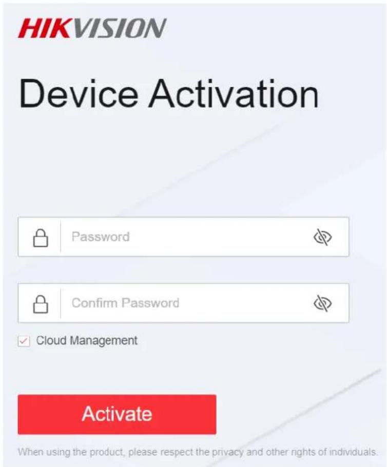
Figure 2-1 Activate Device

Note
- You can obtain the default IP address of the switch using the SADP tool.
- You are recommended to use the following web browsers: Microsoft Edge 89 or later, Google Chrome 89 or later, and Firefox 78 or later.
2. Set a password and confirm the password.

Note
- The password should contain 8 to 16 characters, including at least two types of the following categories: uppercase letters, lowercase letters, digits, and special characters.
- The password cannot contain user name, '123', or 'admin' (case-insensitive), 4 or more consecutively increasing or decreasing digits (such as '1234' and '4321'), or 4 or more identical characters (such as '1111' and 'aaaa').
- The password cannot be a common risky password.
3. Optional: Check Cloud Management.
The Hik-Connect service is enabled.
4. Click OK.
The network configuration page is displayed.
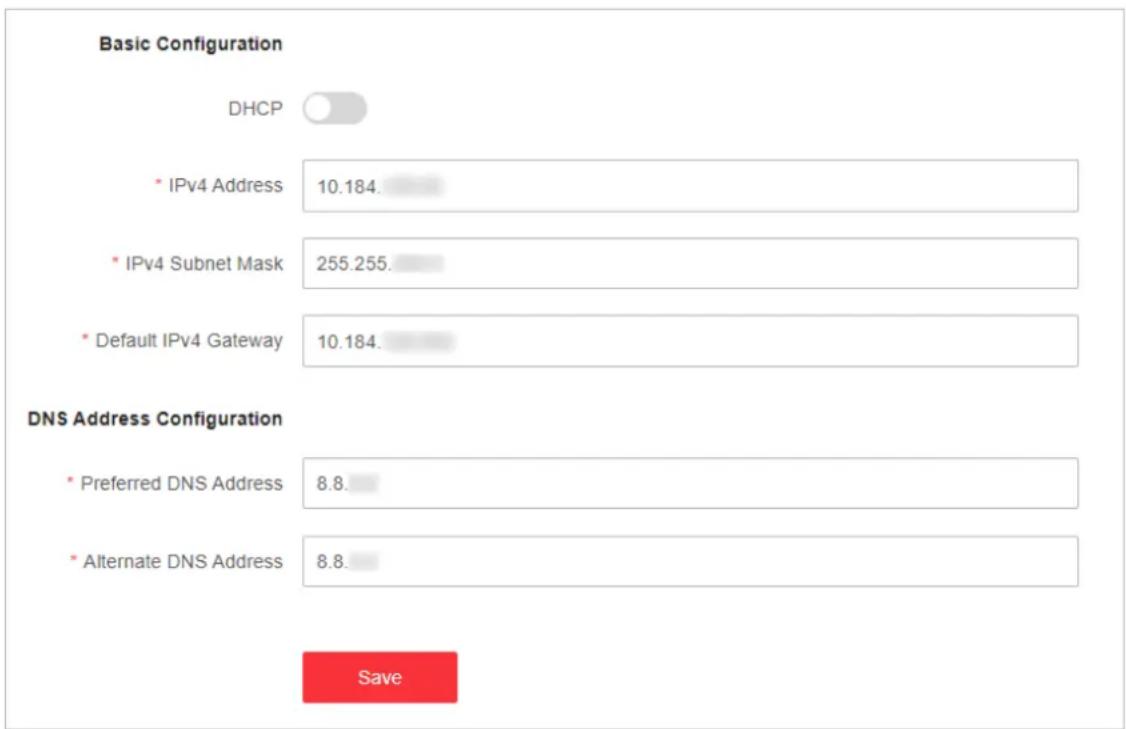
5. Optional: Modify the network configurations.
1) Go to System Management → Network Configuration → Network Configuration.
bar
| Configuration | Value | | :--- | :--- | | Basic Configuration | DHCP | | * IPv4 Address | 10.184 | | * IPv4 Subnet Mask | 255.255 | | * Default IPv4 Gateway | 10.184 | | DNS Address Configuration | | * Preferred DNS Address | 8.8 | | * Alternate DNS Address | 8.8 | SaveFigure 2-2 Modify Network Parameters
2) Modify the IPv4 address, IPv4 subnet mask, default IPv4 gateway, preferred DNS address, and alternate DNS address as required, or enable DHCP for automatic IP address assignment.

You are recommended to modify the network configurations to better manage your switch.
3) Log in to the switch web again with the new IP address after modification.
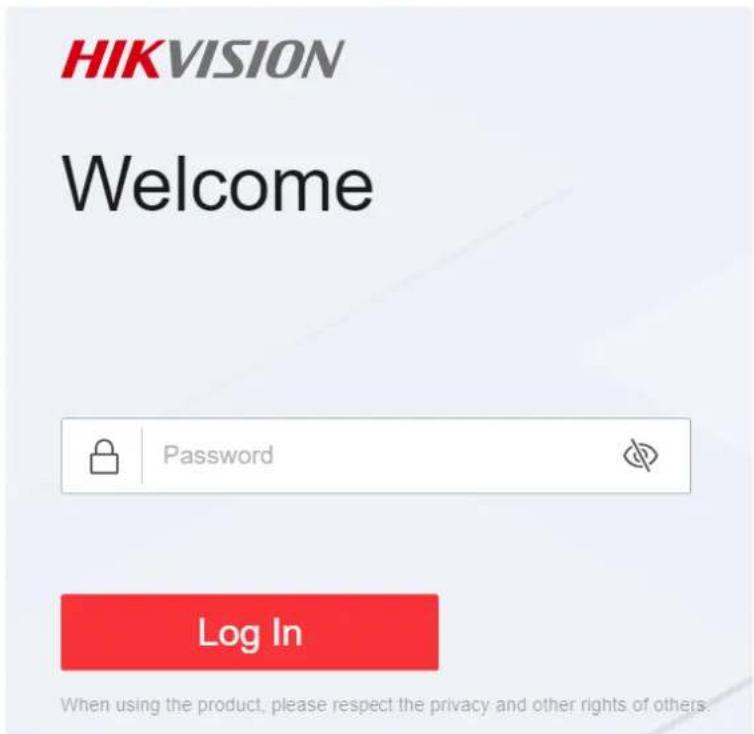
Figure 2-3 Log In
Chapter 3 Device Information
After logging in to the switch web, you can obtain detailed information about the switch, including the device overview information, port status information, and network status information.
3.1 Device Overview
You can view or edit the device overview information on the Overview page.
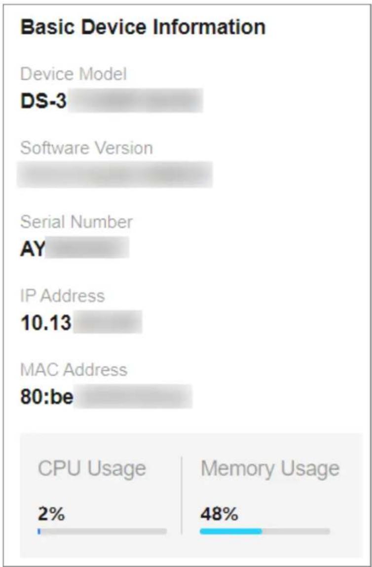
Basic Device Information
You can view the device model, software version, serial number, IP and MAC addresses, as well as CPU and memory usage of the switch in the lower right corner of the Overview page.
bar
Basic Device Information | Component | CPU Usage (%) | Memory Usage (%) | | :--- | :--- | :--- | | Device Model DS-3 | | | | Software Version | | | | Serial Number AY | | | | IP Address | 10.13 | | | MAC Address 80:be | | | | CPU Usage 2% | | Memory Usage 48% |Figure 3-1 View Basic Device Information
Device Name
You can view the current device name or click next to it to customize the device name on the Overview page.

Figure 3-2 Edit Device Name
System Uptime
You can also view the device's system uptime in the upper right corner of the Overview page.
System Uptime: 0 Week(s) 1 Day(s) 21 h 37 min 55 sec
Figure 3-3 View System Uptime
VLANs Added
You can quickly view the number of VLANs that have been added, or click to go to the VLAN Management page for VLAN configuration.

Figure 3-4 View Number of VLANs Added
i Note
You can also view the maximum number of VLANs allowed by the device, for example, 4094 in the figure above. The maximum number of VLANs allowed by a device varies with device models.
Cloud Platform Connection Status
The Cloud Platform module shows whether the device is connected to Hik-Connect.
- If the cloud platform is connected, scan the QR code to add the device to Hik-Partner Pro app for remote management.
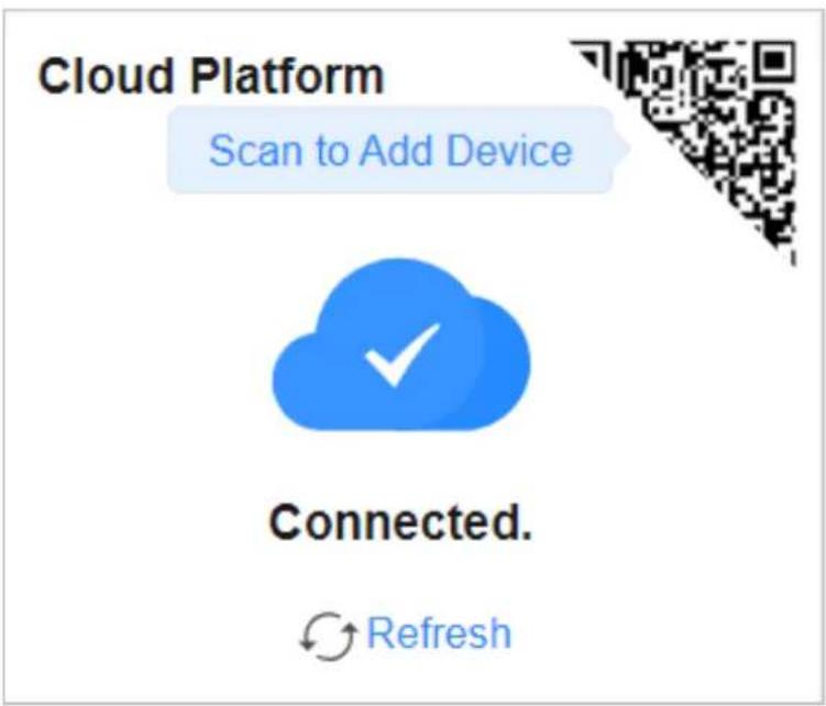
Figure 3-5 View Cloud Platform Connection Status (Connected)
- If the cloud platform is disconnected, click Refresh to reconnect, or click Diagnose to find out the cause of the connection failure and go to the cloud platform configuration page as prompted for cloud platform configuration.
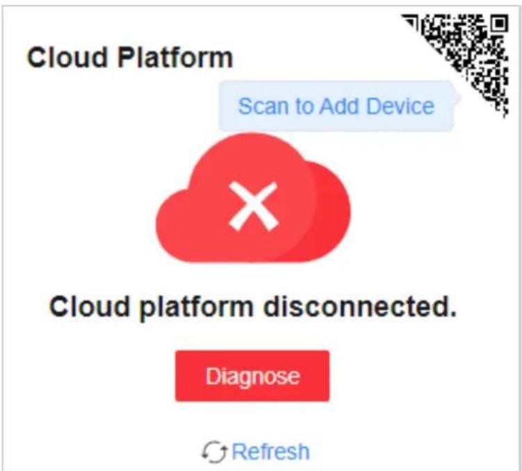
Figure 3-6 View Cloud Platform Connection Status (Disconnected)
3.2 Port Status
The Overview page provides a visual representation of the physical ports and shows the connection or power supply status of each port, making it easier for users to manage switch ports.
Port Panel
The Port Panel module displays the connection and power supply status of each port. When you hover the mouse over a port, the port name, connection status, rate/duplex, flow control status, and packet receiving/sending rate are displayed. If the port is a PoE port, you can view the PoE power of the port.
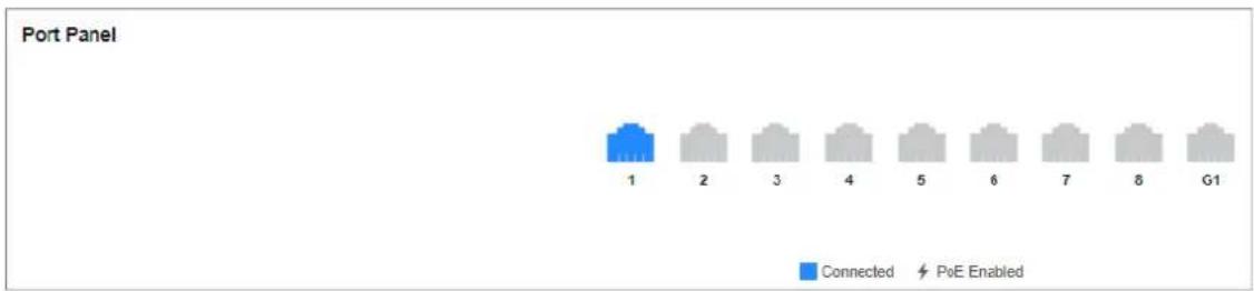
Figure 3-7 View Port Panel
Port Details
The Port Details module lists the status parameters of each port. You can also configure the port status, rate/duplex, and flow control of each port, and view the port name, connection status, and actual rate/duplex of each port.

Figure 3-8 View Port Details
Connection Status
The connection status of a port: Connected or Disconnected.
Port Up
Enable a port (port up) or disable a port (port down). By default, a port is in the up state.
Actual Rate/Duplex
The actual rate and duplex mode of a port.
Configured Rate/Duplex
Configure the rate and duplex mode of a port. The default value is Auto/Auto. You can select different combinations of rates and duplex modes as required.
Flow Control
Enable or disable flow control of a port. By default, flow control is enabled. Enabling flow control can effectively reduce the impact of large amounts of data on the network and maintain the stability of the network.
PoE Power
You can view the whole device PoE power and peak PoE power in last seven days of the switch. Click ☐ in the upper right corner of the module to go to the PoE Management page for PoE function configuration.

Figure 3-9 View PoE Power

Note
PoE power display is only available for switches supporting PoE.
3.3 Network Status
Network Monitoring allows you to view the same-LAN network device information, MAC addresses learned by ports, port statistics, and cable status.
Find Network Devices
Network Device Discovery is a function that automatically detects transmission devices in the same LAN with the switch and displays information about these devices. Go to Network Monitoring → Network Device Discovery, and you can view the device IP address, type, model, and serial No. of the network device(s) found. You can also select a device and click ✉ in the Operation column to go to the web configuration page of the device.
| IP Address | Device Type | Device Model | Serial Number | Operation |
| 10.13 (Local) | Switch | DS-3E130XP-BUM | AY | |
| 10.13 | Switch | DS-3E132SP-BUM | FC | |
| 10.13 | Switch | DS-3E152SP-SI-24P4F | FF | |
| 10.13 | Switch | CR | ||
| 10.13 | Switch | FE | ||
| 10.13 | Switch | E | ||
| 10.13 | Switch | DS-3E152SP-S | AX | |
| 10.13 | Switch | FE |
Figure 3-10 Find Network Devices
Query Port MAC Address
You can query the MAC address(es) learned by each port. Go to Network Monitoring → MAC Address, select the desired port from the Port drop-down list, and click Search. The MAC address(es) learned by the port and type(s) of the MAC address(es) are displayed in the list below.

Figure 3-11 Query Port MAC Addresses
View Port Statistics
You can monitor and collect statistics on the transmitted data of device ports. Go to Network Monitoring → Port Statistics, and you can view the current connection status of each port and the data transmitted by each port in the statistics list.
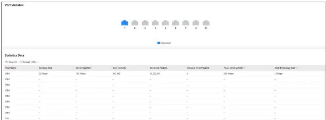
other
Port Statistics | Port Name | Sending Rate | Receiving Rate | Send Packets | Received Packets | Included Error Packets | Peak Sending Rate (%) | Peak Receiving Rate (%) | |---|---|---|---|---|---|---|---| | EHI | 13.96bps | 154.80bps | 542.490 | 14.222.5015 | 8 | 234.96bps | 1.56bps | | EHO | - | - | - | - | - | - | - | | EHI | - | - | - | - | - | - | - | | EHI | - | - | - | - | - | - | - | | EHO | - | - | - | - | - | - | - | | EHI | - | - | - | - | - | - | - | | EHT | - | - | - | - | - | - | - | | EHO | - | - | - | - | - | - | - | | OHI | - | - | - | - | - | - | - | Statistics Data □ Clear Air □ Refrave (OSM) ▼ ■ DescendedFigure 3-12 View Port Statistics
You can also perform the following operations:
- Clear port statistics: You can click Clear All to clear all the port statistics.
- Manually refresh port statistics: You can click 📄 to manually refresh the port statistics.
- Auto refresh port statistics: You can set the interval for automatically refreshing port statistics: 30 seconds or 60 seconds.
Detect Cable Status
Cable Detection is a function that detects the statuses of Ethernet port cables, for example, to check whether there is a short circuit or an open circuit in the receiving or sending direction of a cable, and if any, to locate the faulty cable. Go to Network Monitoring → Cable Detection, select the desired port on the left port panel, and click Detect to view the detection result.
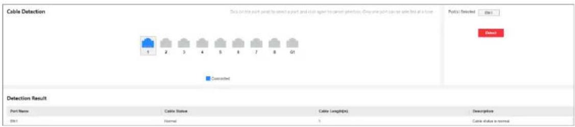
Figure 3-13 Detect Cable Status
Diagnose Network
Ping is a function that helps to diagnose network connectivity and quickly locate network faults.
- Click Network Monitoring → Ping.
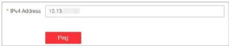
Figure 3-14 Ping
-
Enter a network server address in the IPv4 address field.
-
Click Ping.

Note
The network diagnosis result is displayed in the Ping Result area.
Chapter 4 Device Configuration
4.1 Port Configuration
4.1.1 Configure Port Attributes
The basic attributes can influence the working status of a port. Set the parameters as required.
Steps
- Go to L2 Configuration → Port Attributes.
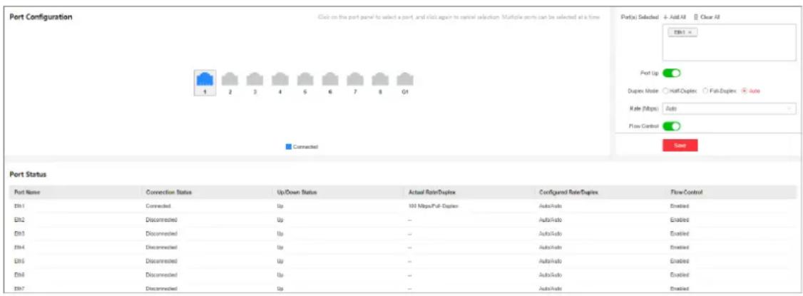
Figure 4-1 Configure Port Attributes
- Select the desired port(s) and configure the parameters.
Port Up
Enable or disable the selected port(s). If a port is enabled, it is in the up state; if a port is disabled, it is in the down state. No data will be transmitted on a "down" port.
Duplex Mode
The duplex mode of a port. The configurable duplex modes of ports include Half-Duplex, Full-Duplex, and Auto, which may vary with device models.
Rate (Mbps)
The data transmission speed of a port of a port. The configurable rates of ports include 10M, 100M, 1000M, and Auto, which may vary with device models.
Flow Control
Enable or disable flow control of a port. Enabling flow control can prevent data loss in data transmission.
-
Click Save.
-
Optional: View the port attributes in the port status list.
4.1.2 Configure Link Aggregation
Link aggregation is used to combine multiple physical links together to make a logical high-bandwidth data path, which provides a stronger and faster network connection.
Steps
-
Go to L2 Configuration → Link Aggregation.
-
Click
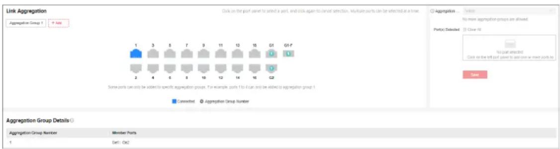
Figure 4-2 Configure Link Aggregation
- Select at least two desired ports.

Note
- Only the selectable ports can be added to an aggregation group.
- 2 to 4 ports are allowed for each link aggregation group.
- Some ports can only be added to a specific aggregation group. Please refer to the actual situation.
-
The rate, duplex mode, flow control, long-range mode, and VLAN configurations of ports in one aggregation group should be the same.
-
Set Aggregation Group Number.

Note
The number of aggregation groups allowed varies.
-
Click Save.
-
Optional: Edit the aggregation group.
1) Click an existing aggregation group, for example, "Aggregation Group 1".
2) Select the desired port(s) on the left port panel to add to the group, or deselect the desired port(s) on the right to delete from the group.
3) Click Edit to save the modification.
- Optional: Delete the aggregation group.
1) Click an existing aggregation group, for example, "Aggregation Group 1".
2) Click Delete on the right.
- Optional: View the member ports of each aggregation group in the list below.
4.1.3 Configure Port Isolation
Port isolation is a feature to add multiple ports to an isolation group so that ports in the same isolation group cannot communicate with each other. For example, by using port isolation function, you can achieve the goal of preventing PCs under different ports communicating with each other without configuring VLANs.
Steps
- Go to Security → Port Isolation.
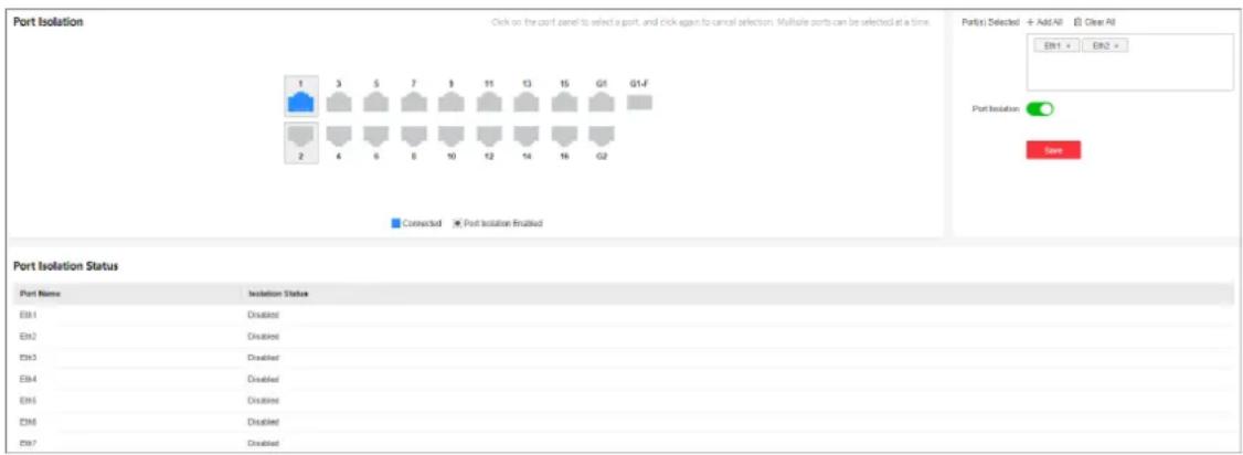
Figure 4-3 Configure Port Isolation
- Select the desired port(s) on the port panel.

Note
You can also click or on the right to batch select or deselect all ports.
- Enable or disable Port Isolation as required.
- Click Save.
- Optional: View the port isolation status of each port in the Port Isolation Status list.
4.1.4 Configure Port Mirroring
Port mirroring is a feature in network switches that allows administrators to monitor traffic on one port (mirrored port) and replicate this data to another port (mirroring port) for analysis. This replication occurs in real-time, allowing an administrator to view a "mirror" or exact duplicate of the traffic moving on the mirrored port.
Steps
- Go to L2 Configuration → Port Mirroring.
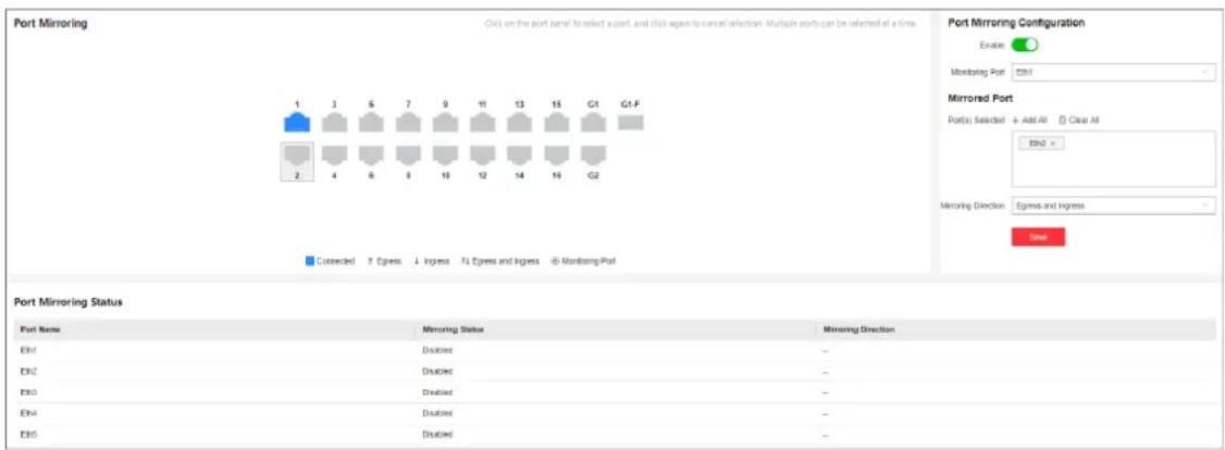
Figure 4-4 Configure Port Mirroring
- Select the desired port(s) on the port panel as the mirrored port(s), and set the parameters as required.

Note
You can also click -or on the right to batch select or deselect all ports.
Enable
Enable or disable port mirroring of the selected port(s).
Monitoring Port
Only one port can be set as the monitoring port (mirroring port).
Mirroring Direction
Ingress
The data received by the source port will be under monitoring.
Egress
The data sent by the source port will be under monitoring.
Egress and Ingress
Both the data received by and the data sent from the source port will be under monitoring.
- Click Save.

Note
The latest configuration will overwrite the previous configuration.
- Optional: View the mirroring status of each port in the Port Mirroring Status list.
4.1.5 Configure Long-Range Mode
After the long-range mode is enabled for a port, the transmission distance of the port can reach 300 meters at a rate of 10 Mbps.
Steps
- Go to L2 Configuration → Long-Range Mode.
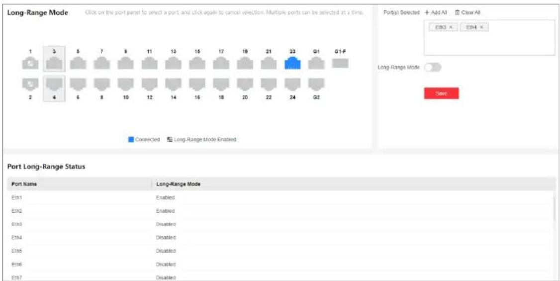
Figure 4-5 Configure Long-Range Mode
- Select the desired port(s) on the port panel.

Note
You can also click or on the right to batch select or deselect all ports.
- Enable or disable Long-Range Mode as required.
- Click Save.
- Optional: View the long-range status of each port in the Port Long-Range Status list.
4.1.6 Configure High-Priority Port
High-priority ports are identified by a red area on the device front panel. In the case of uplink congestion, the data of ports in this area is preferentially transmitted.
Steps
- Go to Service Quality → High-Priority.

Note
High-priority port configuration is only supported when the switch has high-priority ports.
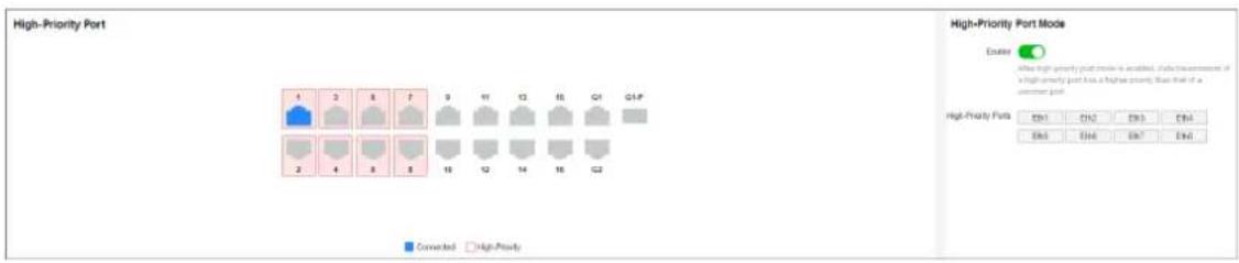
Figure 4-6 Configure High-Priority Port
- In High-Priority Port Mode, toggle on Enable to batch enable high-priority ports.

Note
The number of high-priority ports varies with different device models. Please refer to the actual situation.
All high-priority ports of the switch are enabled, with a higher data transmission priority than common ports.
4.2 PoE Configuration
Click PoE Management in the left navigation pane.
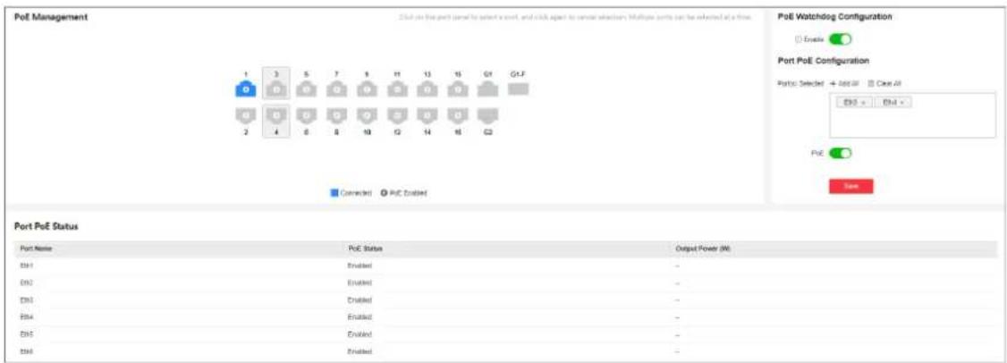
Figure 4-7 Configure PoE
PoE Watchdog
Enable PoE watchdog to auto-detect and restart IP cameras that do not respond.
Port PoE Configuration
Select the desired port(s) on the port panel and enable PoE to supply power to the powered device(s) connected to the port(s).

Note
You can click +or add A to batch select or deselect all ports.
PoE Status
View the PoE enabling status and output power of PoE ports in the Port PoE Status list.
4.3 VLAN Configuration
Virtual Local Area Networks (VLANs) separate an existing physical network into multiple logical networks. Thus, each VLAN creates its own broadcast domain. With VLANs configured on a switch, users in the same VLAN can communicate with each other, while users in different VLANs are isolated. In this way, different broadcast domains are isolated, enhancing network security.
4.3.1 Add VLAN
Steps
- Click VLAN Management in the left navigation pane.
- In Global VLAN Configuration, click Edit.
- Click Add.
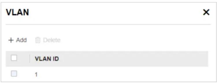
Figure 4-8 Add VLAN(s)
-
Select an adding mode.
-
Single: Only one VLAN is added at a time.
- Batch: Multiple VLANs are added in a batch.
- Single: Only one VLAN is added at a time.
- Batch: Multiple VLANs are added in a batch.

Note
The maximum number of VLANs that can be added in a batch varies with device models. Please refer to the actual situation.
-
Set VLAN ID.
-
Single: Enter a VLAN ID.
- Batch: Enter the start VLAN ID and end VLAN ID.
i Note
- The VLAN ID should be an integer between 1 and the maximum number of VLANs allowed by the device. For example, if the maximum number of VLANs allowed is 4094, the VLAN ID should be integer between 1 and 4094.
- The end VLAN ID should be greater than the start VLAN ID.
- The number of VLANs to be batch added should be no more than the maximum number of VLANs that can be added in a batch. For example, in the case that the maximum number of VLANs that can be added in a batch is 128, if you set the start VLAN ID to 1, the end ID cannot be greater than 128.
6. Click Save.
- Optional: Select the desired VLAN(s) and click Delete to delete one or more VLANs.
iNote
The default VLAN 1 cannot be deleted.
4.3.2 Configure Port VLAN
Steps
- Select the desired port(s) on the port panel.
iNote
-
You can also click or on the right to batch select or deselect all ports.
• VLAN configuration is not allowed for ports in an aggregation group. -
Configure the port VLAN type.
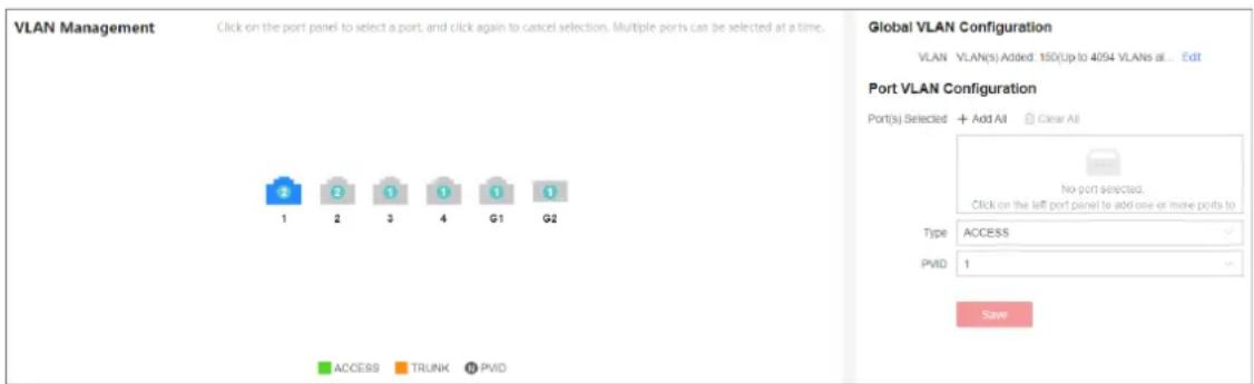
Figure 4-9 Configure Port VLAN
- ACCESS: An ACCESS port can have only one VLAN configured on the interface, and it can carry traffic for only one VLAN, usually the default VLAN (VLAN 1). Select Type as ACCESS, and set PVID.
-
TRUNK: A TRUNK port can have two or more VLANs configured on the interface, and it can carry traffic for several VLANs simultaneously. Select Type as TRUNK, set PVID, and enter Accessible VLANs.
-
Click Save.
- Optional: View the VLAN configuration information of each port in the port VLAN details list.
| Port VLAN Details | |||
| Port Name | Type | PVID | Accessible VLANs |
| Eth1 | ACCESS | 1 | 1 |
| Eth2 | ACCESS | 1 | 1 |
| Eth3 | ACCESS | 2 | 2 |
| Eth4 | ACCESS | 2 | 2 |
| Eth5 | ACCESS | 1 | 1 |
| Eth6 | ACCESS | 1 | 1 |
Figure 4-10 Port VLAN Details
4.4 STP Configuration
Spanning Tree Protocol (STP) is a layer-2 link management protocol that provides path redundancy and prevents loops in a network topology. STP uses a spanning-tree algorithm to select one switch as the root of a spanning tree, and determines the network topology by transmitting Bridge Protocol Data Unit (BPDU) packets between devices, helping to create a stable network.
Steps
- Go to L2 Configuration → STP.
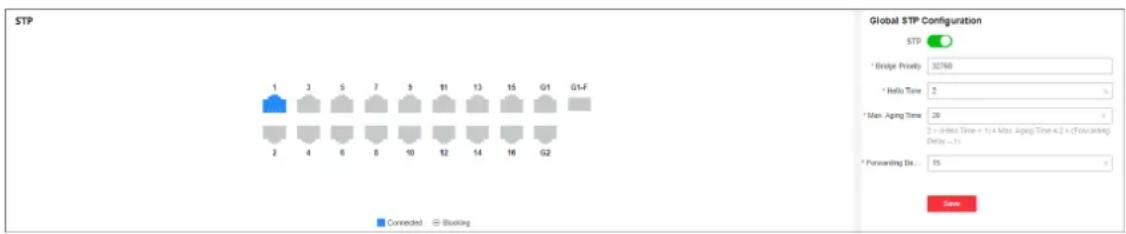
Figure 4-11 Configure STP
- In Global STP Configuration, enable STP.
- Set STP parameters as required.
Table 4-1 STP Parameters
| Parameter Description | |
| Bridge Priority | The value ranges from 0 to 61440, in an increment of 4096. The default value is 32768. Valid values are 0, 4096, 8192, 12288, 16384, ..., and 61440.The smaller the value, the higher the bridge priority of a switch. A switch with higher bridge priority is more likely to become the root bridge. |
| Hello Time The interval | val between each BPDU that is sent on a port, which is used for port link diagnosis. The value ranges from 1 to 10 seconds. The default value is 2 seconds. |
| Max. Aging Time The | maximum length of time interval that a STP-enabled switch port saves its configuration BPDU information. The value ranges from 6 to 40 seconds. The default value is 20 seconds. NoteThe Max. aging time must meet the following conditions: 2 × (Hello Time + 1) ≤ Max. Aging Time ≤ 2 × (Forwarding Delay – 1) NoteThe Max. aging time must meet the following conditions: 2 × (Hello Time + 1) ≤ Max. Aging Time ≤ 2 × (Forwarding Delay – 1) |
| Forwarding Delay The | the time interval that is spent in the listening and learning state when the topology changes. The value ranges from 4 to 30 seconds. The default value is 15 seconds. |
-
Click Save.
-
Optional: Click Port Status or STP Status to view the STP status of each port or global STP configuration.

Note
- The Port Status information includes the port name, path cost, port role, and port status.
- The STP Status information includes the bridge ID, root bridge ID, as well as hello time, Max. aging time, and forwarding delay of the root bridge.
4.5 LLDP Configuration
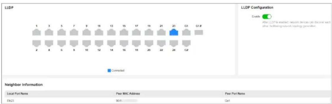
Link Layer Discovery Protocol (LLDP) is a layer 2 neighbor discovery protocol that allows devices to advertise device information to their directly connected peers/neighbors. With LLDP enabled, network devices can send LLDP data units (LLDPDUs) to inform other devices of their status. LLDP helps to draw network topology and detect improper configurations in a network.
Steps
- Go to L2 Configuration → LLDP.
- Enable or disable LLDP.
other
LLDP Configuration | Node | LLDP Name | Peer MAC Address | Peer Port Name | |---|---|---|---| | 1 | Local Port Name | 90 ft | Gel | | 2 | Local Port Name | 90 ft | 90 ft | | 3 | Local Port Name | 90 ft | 90 ft | | 4 | Local Port Name | 90 ft | 90 ft | | 5 | Local Port Name | 90 ft | 90 ft | | 6 | Local Port Name | 90 ft | 90 ft | | 7 | Local Port Name | 90 ft | 90 ft | | 8 | Local Port Name | 90 ft | 90 ft | | 9 | Local Port Name | 90 ft | 90 ft | | 10 | Local Port Name | 90 ft | 90 ft | | 11 | Local Port Name | 90 ft | 90 ft | | 12 | Local Port Name | 90 ft | 90 ft | | 13 | Local Port Name | 90 ft | 90 ft | | 14 | Local Port Name | 90 ft | 90 ft | | 15 | Local Port Name | 90 ft | 90 ft | | 16 | Local Port Name | 90 ft | 90 ft | | 17 | Local Port Name | 90 ft | 90 ft | | 18 | Local Port Name | 90 ft | 90 ft | | 19 | Local Port Name | 90 ft | 90 ft | | 20 | Local Port Name | 90 ft | 90 ft | | 21 | Local Port Name | 90 ft | 90 ft | | 22 | Local Port Name | 90 ft | 90 ft | | 23 | Local Port Name | 90 ft | 90 ft | | G1 | G1-F | 90 ft | 90 ft | | G2 | G2-F | 90 ft | 90 ft | Neighbor Information Local Port Name Peer MAC Address Peer Port Name Ebl23 90 ft GelFigure 4-12 Configure LLDP

Note
After LLDP is enabled, network devices can discover each other, facilitating network topology drawing.
- Optional: View the local port(s), MAC address(es) of peer device(s), and peer port(s) in the Neighbor Information list.
Chapter 5 System Management
5.1 Network Configuration
You can click 📄 on the home page to check Hik-Connect connection status, or go to System Management → Network Configuration for network configuration, cloud platform configuration, and SADP configuration.
Network Configuration
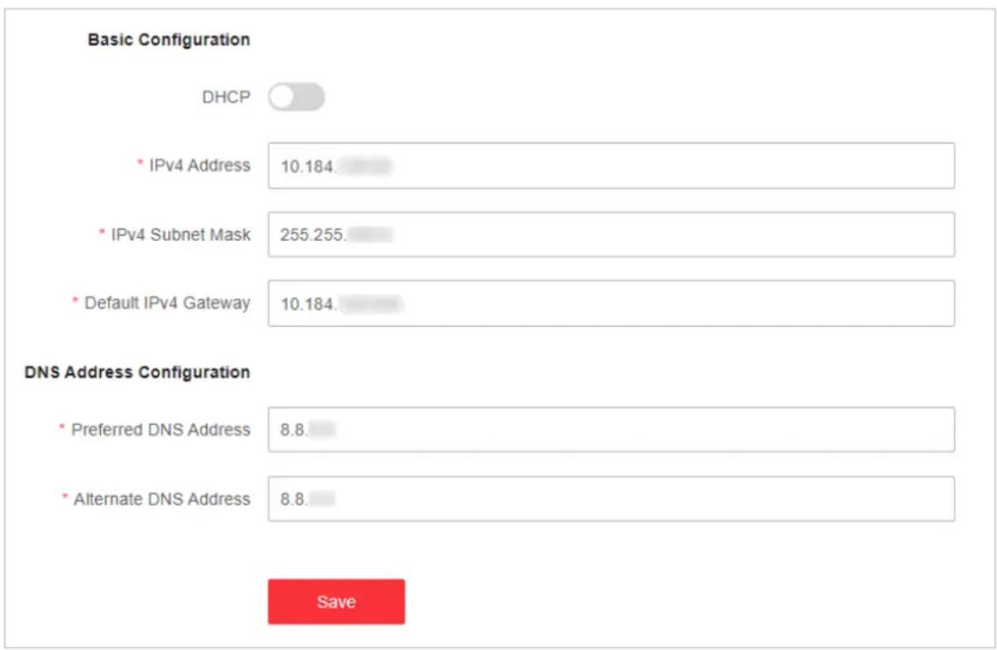
Figure 5-1 Configure Network
Set the IPv4 address, IPv4 subnet mask, default IPv4 gateway, preferred DNS address, and alternate DNS address as required, or enable DHCP for automatic IP address assignment.
Cloud Platform Configuration
If the device is displayed as offline when you add it to Hik-Partner Pro, you need to modify the DNS server address and configure Hik-Connect parameters.
Go to System Management → Network Configuration → Cloud Platform Configuration, and ensure that Hik-Connect is enabled. You can also check the operation code, and bind the device to your cloud account on Hik-Partner Pro app.
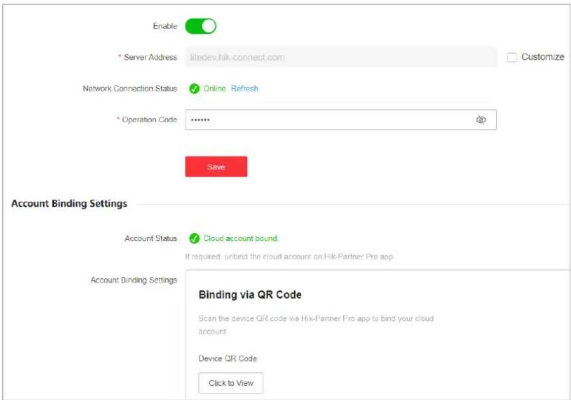
Figure 5-2 Configure Cloud Platform

Note
It takes several minutes for reconnecting to Hik-Connect service.
SADP Configuration
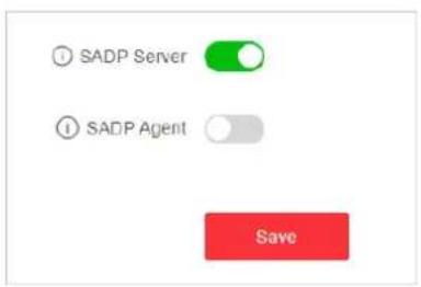
Figure 5-3 Configure SADP
Enable SADP Server or SADP Agent as required.

Note
- After SADP server is enabled, devices supporting SADP can be searched and information about the devices is displayed.
- After SADP agent is enabled, query requests are sent to the LAN periodically (every minute) for network topology drawing.
Remote Management
Go to System Management → Network Configuration → Remote Management for remote device management via HTTP or HTTPS.
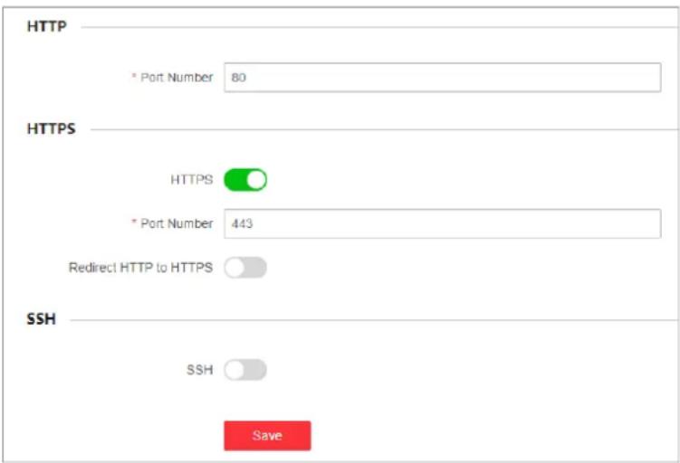
Figure 5-4 Manage Device Remotely
- HTTP: Set Port Number and click Save.

Note
The HTTP port number should be an integer between 2000 and 65535, or 80 by default.
- HTTPS: Set the parameters as required and click Save.
HTTPS
Enable or disable HTTPS.
Port Number
If HTTPS is enabled, set the HTTPS port number.

Note
The HTTPS port number should be an integer between 2000 to 65535, or 443 by default.
Redirect HTTP to HTTPS
Enable or disable Redirect HTTP to HTTPS.
i Note
If Redirect HTTP to HTTPS is enabled, traffic accessed through port 80 will be automatically redirected to port 443.
- SSH: SSH is used for fault locating by technical support, and is not available to users.
5.2 Time Synchronization
Steps
- Go to System Management → Time Configuration.
- Set Time Zone.
- Set Time Sync Mode.
- Manually: Manually set the date and time, or check Sync with Computer Time to synchronize the system date and time.
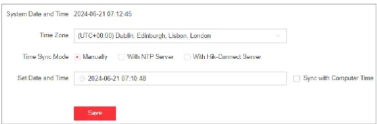
Figure 5-5 Configure Time Manually
- With NTP Server: Enter the NTP server address, port number, and time sync interval for automatic time synchronization.
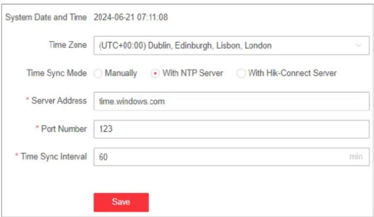
Figure 5-6 Configure Time with NTP Server
- With Hik-Connect Server: Use the Hik-Connect server for automatic time calibration and synchronization. You do not need to configure any parameters.
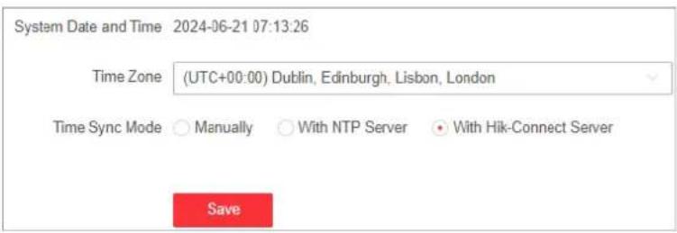
Figure 5-7 Configure Time with Hik-Connect Server
- Click Save.
5.3 System Maintenance
Go to System Management → System Maintenance to restart, upgrade, back up, or reset the device.
Restart Device
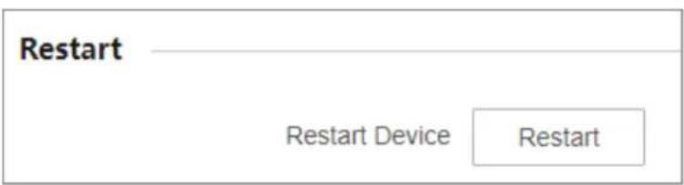
Figure 5-8 Restart
In Restart, click Restart to remotely restart the switch.
i Note
You will enter the login page automatically after the device is restarted.
Upgrade Device
Upload an upgrade file to upgrade the switch.

Figure 5-9 Upgrade
- In Upgrade, click ☐ to select an upgrade patch file.
- Click Upgrade.

Note
- If upgrading failed or the device cannot function, please contact our technical support engineers.
- The device will restart automatically to enter the login page after upgrade is completed.
Back Up Device
Export the configuration file for local backup.
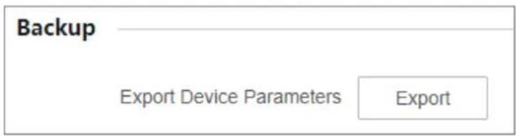
Figure 5-10 Back Up
- In Backup, click Export to export the configuration file containing device parameters.
- Set a password and confirm the password for file encryption.

Note
Remember the password as it is required when importing device parameters.
- Click OK.
Reset Device
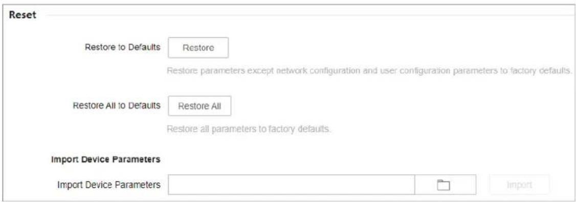
Figure 5-11 Reset
- Restore to Defaults: Click Restore to restore parameters except network configuration and user configuration parameters to factory defaults.
- Restore All to Defaults: Click Restore All to restore all parameters to factory defaults.
i Note
- The device parameters cannot be recovered once being restored to factory defaults.
- The device will restart automatically after being restored to factory defaults.
- Import Device Parameters: Click ☐ to select the configuration file containing device parameters, click Import, enter the password for file decryption, and then click OK to import the configuration file for fast device configuration.
i Note
The device will restart automatically to enter the login page after the configuration file is imported.
5.4 Log Management
System operation logs can be searched and exported for backup.
Steps
- Go to System Management → System Maintenance → Log Management.
| Major Type Subtype Date and Time | ||||||
| All All 2000-01-01 00:00:00 2024-06-21 23:59:59 Search Export | ||||||
| No. | Operation Time | Major Type | Subtype | Remote Operator | Remote Host IP Address | Description |
| 01 | 2024-06-21 16:53:55 | Operation | Remote User Login | admin | 10.184 | (HTTP) |
| 02 | 2024-06-21 15:21:47 | Operation | Remote User Login | admin | 10.184 | (HTTP) |
| 03 | 2024-06-21 14:52:21 | Operation | Remote User Login | admin | 10.13 | (HTTP) |
| 04 | 2024-06-21 14:51:20 | Operation | Remote User Login | admin | 10.9 | (HTTP) |
| 05 | 2024-06-21 14:45:58 | Operation | Remote User Login | admin | 10.9 | (HTTP) |
| 06 | 2024-06-21 14:45:08 | Operation | Remote User Login | admin | 10.9 | (HTTP) |
| 07 | 2024-06-21 14:42:22 | Operation | Remote User Login | admin | 10.9 | (HTTP) |
| 08 | 2024-06-21 06:36:52 | Operation | Remote User Login | admin | 10.13 | (HTTP) |
| 09 | 2024-06-21 06:36:24 | Event | Port Link Up | None | None | (Eth2) |
| 10 | 2024-06-21 06:36:19 | Event | Port Link Down | None | None | (Eth1) |
Figure 5-12 Manage Logs
-
Set search conditions, including Major Type, Subtype, and Date and Time.
-
Click Search.
iNote
A maximum of 1024 search results can be displayed. Please narrow down the search scope if there are too many search results.
- Optional: Click Export to export all the search results.
iNote
Logs can be exported as a TXT file. A prompt will pop up after logs are exported successfully.

See Far, Go Further
- Smart Managed Switch Web
- Legal Information
- About this Document
- About this Product
- Acknowledgment of Intellectual Property Rights
- LEGAL DISCLAIMER
- Preface
- Applicable Models
- About Defaults
- Note
- Symbol Conventions
- Contents
- Chapter 1 Introduction ...... 1
- Chapter 2 Activation and Login ...... 2
- Chapter 3 Device Information .... 5
- Chapter 4 Device Configuration .... 13
- Chapter 5 System Management 24
- Chapter 1 Introduction
- i Note
- Chapter 2 Activation and Login
- Before You Start
- Steps
- Set a password and confirm the password.
- Optional: Check Cloud Management.
- Click OK.
- Optional: Modify the network configurations.
- Chapter 3 Device Information
- Device Overview
- Basic Device Information
- Device Name
- System Uptime
- VLANs Added
- Cloud Platform Connection Status
- Port Status
- Port Panel
- Port Details
- Connection Status
- Port Up
- Actual Rate/Duplex
- Configured Rate/Duplex
- Flow Control
- PoE Power
- Network Status
- Find Network Devices
- Query Port MAC Address
- View Port Statistics
- Detect Cable Status
- Diagnose Network
- Chapter 4 Device Configuration
- Port Configuration
- Configure Port Attributes
- Duplex Mode
- Rate (Mbps)
- Configure Link Aggregation
- Configure Port Isolation
- Configure Port Mirroring
- Enable
- Monitoring Port
- Mirroring Direction
- Ingress
- Egress
- Egress and Ingress
- Configure Long-Range Mode
- Configure High-Priority Port
- PoE Configuration
- PoE Watchdog
- Port PoE Configuration
- PoE Status
- VLAN Configuration
- Add VLAN
- Click Save.
- iNote
- Configure Port VLAN
- STP Configuration
- LLDP Configuration
- Chapter 5 System Management
- Network Configuration
- Network Configuration
- Cloud Platform Configuration
- SADP Configuration
- Remote Management
- HTTPS
- Port Number
- Redirect HTTP to HTTPS
- Time Synchronization
- System Maintenance
- Restart Device
- Upgrade Device
- Back Up Device
- Reset Device
- Log Management
Brand : Hikvision
Model : DS-3E1516-EI
Category : Network switch