
DS-3E1552P-SI - Network switch Hikvision - Free user manual and instructions
Find the device manual for free DS-3E1552P-SI Hikvision in PDF.


| Product type | Network Switch (Gigabit PoE+) |
| Model | DS-3E1552P-SI |
| Brand | Hikvision |
| Number of ports | 48 x 10/100/1000Base-T PoE+ ports + 4 x Gigabit SFP slots |
| PoE budget | 370W |
| Switching capacity | 104 Gbps |
| Packet forwarding rate | 77.38 Mpps |
| Power supply | AC 100-240V, 50/60Hz |
| Power consumption (max) | 450W (with PoE) |
| Dimensions (W x D x H) | 440 x 284 x 44 mm (1U rack-mountable) |
| Weight | Approximately 4.5 kg |
| Operating temperature | 0°C to 40°C |
| Storage temperature | -40°C to 70°C |
| Management | Web-based, SNMP, CLI |
| Safety features | Overload protection, surge protection, short-circuit protection |
| Maintenance | Clean with a soft, dry cloth. Avoid liquids and cleaning agents. |
| Spare parts | Replacement power supply unit, fan modules |
| Repairability | Contact authorized service center for repairs |
| Warranty | 2 years (typical) |
Frequently Asked Questions - DS-3E1552P-SI Hikvision
User questions about DS-3E1552P-SI Hikvision
0 question about this device. Answer the ones you know or ask your own.
Ask a new question about this device
Download the instructions for your Network switch in PDF format for free! Find your manual DS-3E1552P-SI - Hikvision and take your electronic device back in hand. On this page are published all the documents necessary for the use of your device. DS-3E1552P-SI by Hikvision.
USER MANUAL DS-3E1552P-SI Hikvision
©2022 Hangzhou Hikvision Digital Technology Co., Ltd. All rights reserved.
About this Manual
The Manual includes instructions for using and managing the Product. Pictures, charts, images and all other information hereinafter are for description and explanation only. The information contained in the Manual is subject to change, without notice, due to firmware updates or other reasons. Please find the latest version of this Manual at the Hikvision website (https://www.hikvision.com/).
Please use this Manual with the guidance and assistance of professionals trained in supporting the Product.
Trademarks
HIKVISION and other Hikvision's trademarks and logos are the properties of Hikvision in various jurisdictions.
Other trademarks and logos mentioned are the properties of their respective owners.
Disclaimer
TO THE MAXIMUM EXTENT PERMITTED BY APPLICABLE LAW, THIS MANUAL AND THE PRODUCT DESCRIBED, WITH ITS HARDWARE, SOFTWARE AND FIRMWARE, ARE PROVIDED "AS IS" AND "WITH ALL FAULTS AND ERRORS". HIKVISION MAKES NO WARRANTIES, EXPRESS OR IMPLIED, INCLUDING WITHOUT LIMITATION, MERCHANTABILITY, SATISFACTORY QUALITY, OR FITNESS FOR A PARTICULAR PURPOSE. THE USE OF THE PRODUCT BY YOU IS AT YOUR OWN RISK. IN NO EVENT WILL HIKVISION BE LIABLE TO YOU FOR ANY SPECIAL, CONSEQUENTIAL, INCIDENTAL, OR INDIRECT DAMAGES, INCLUDING, AMONG OTHERS, DAMAGES FOR LOSS OF BUSINESS PROFITS, BUSINESS INTERRUPTION, OR LOSS OF DATA, CORRUPTION OF SYSTEMS, OR LOSS OF DOCUMENTATION, WHETHER BASED ON BREACH OF CONTRACT, TORT (INCLUDING NEGLIGENCE), PRODUCT LIABILITY, OR OTHERWISE, IN CONNECTION WITH THE USE OF THE PRODUCT, EVEN IF HIKVISION HAS BEEN ADVISED OF THE POSSIBILITY OF SUCH DAMAGES OR LOSS.
YOU ACKNOWLEDGE THAT THE NATURE OF THE INTERNET PROVIDES FOR INHERENT SECURITY RISKS, AND HIKVISION SHALL NOT TAKE ANY RESPONSIBILITIES FOR ABNORMAL OPERATION, PRIVACY LEAKAGE OR OTHER DAMAGES RESULTING FROM CYBER-ATTACK, HACKER ATTACK, VIRUS INFECTION, OR OTHER INTERNET SECURITY RISKS; HOWEVER, HIKVISION WILL PROVIDE TIMELY TECHNICAL SUPPORT IF REQUIRED.
YOU AGREE TO USE THIS PRODUCT IN COMPLIANCE WITH ALL APPLICABLE LAWS, AND YOU ARE SOLELY RESPONSIBLE FOR ENSURING THAT YOUR USE CONFORMS TO THE APPLICABLE LAW. ESPECIALLY, YOU ARE RESPONSIBLE, FOR USING THIS PRODUCT IN A MANNER THAT DOES NOT INFRINGE ON THE RIGHTS OF THIRD PARTIES, INCLUDING WITHOUT LIMITATION, RIGHTS OF PUBLICITY, INTELLECTUAL PROPERTY RIGHTS, OR DATA PROTECTION AND OTHER PRIVACY RIGHTS. YOU SHALL NOT USE THIS PRODUCT FOR ANY PROHIBITED END-USES, INCLUDING THE
DEVELOPMENT OR PRODUCTION OF WEAPONS OF MASS DESTRUCTION, THE DEVELOPMENT OR PRODUCTION OF CHEMICAL OR BIOLOGICAL WEAPONS, ANY ACTIVITIES IN THE CONTEXT RELATED TO ANY NUCLEAR EXPLOSIVE OR UNSAFE NUCLEAR FUEL-CYCLE, OR IN SUPPORT OF HUMAN RIGHTS ABUSES.
IN THE EVENT OF ANY CONFLICTS BETWEEN THIS MANUAL AND THE APPLICABLE LAW, THE LATTER PREVAILS.
Preface
Applicable Models
This manual is applicable to the iVMS-4200 client of switches.
Symbol Conventions
The symbols that may be found in this document are defined as follows.
| Symbol Description | |
 Danger Danger | Indicates a hazardous situation which, if not avoided, will or could result in death or serious injury. |
 Caution Caution | Indicates a potentially hazardous situation which, if not avoided, could result in equipment damage, data loss, performance degradation, or unexpected results. |
 Note Note | Provides additional information to emphasize or supplement important points of the main text. |
Safety Instructions

Danger
- This is a class A product and may cause radio interference in which case the user may be required to take adequate measures.
- Ensure that your devices powered via the PoE port have their shells protected and fire-proofed, because the switches are not compliant with the Limited Power Source (LPS) standard.
- In the use of the product, you must be in strict compliance with the electrical safety regulations of the nation and region.
- The socket-outlet shall be installed near the device and shall be easily accessible.
- The device must be connected to an earthed mains socket-outlet.
• Install the device according to the instructions in this manual. - 12 indicates hazardous live and the external wiring connected to the terminals requires installation by an instructed person.
-
Keep body parts away from fan blades. Disconnect the power source during servicing.
-
Never place the device in an unstable location. The device may fall, causing serious personal injury or death.
- This device is not suitable for use in locations where children are likely to be present.

Caution
- CAUTION: Double pole/Neutral fusing. After operation of the fuse, parts of the device that remain energized might represent a hazard during servicing.
- The device has been designed, when required, modified for connection to an IT power distribution system.
- This device is suitable for mounting on concrete or other non-combustible surface only.
- The ventilation should not be impeded by covering the ventilation openings with items, such as newspapers, table-cloths, curtains, etc. The openings shall never be blocked by placing the device on a bed, sofa, rug or other similar surface.
- No naked flame sources, such as lighted candles, should be placed on the device.
- The device shall not be exposed to dripping or splashing and that no objects filled with liquids, such as vases, shall be placed on the device.
- Burned fingers when handling the cover area of the device. Wait one-half hour after switching off before handling the parts.
• CLASS 1 LASER PRODUCT

Contents
Chapter 1 Product Introduction .... 1
Chapter 2 Device Management .... 2
2.1 Activate Device 2
2.2 Add Device 4
Chapter 3 Device Status .... 6
Chapter 4 Topology Management .... 7
4.1 Related Operations 7
4.2 Topology Settings 8
Chapter 5 Network Configuration ...... 10
Chapter 6 Device Configuration .... 13
6.1 Port Configuration 13
6.1.1 Attribute Configuration 13
6.1.2 Long-Range Port Configuration 14
6.1.3 PoE Port Configuration 15
6.2 Link Aggregation Configuration 16
Chapter 7 System Configuration .... 19
7.1 Device Information 19
7.2 User Management 19
7.3 Device Maintenance 20
7.4 Log Management 21
7.5 Security Configuration 23
7.6 Time Configuration 24
Chapter 8 Appendix ...... 25
8.1 Communication Matrix 25
8.2 Device Command 25
Chapter 1 Product Introduction
The switches support management through the iVMS-4200 client, including network topology management, network configuration, port management, etc.

Note
All pictures in this manual are only for illustration, and the specific interfaces are subject to the actual device.
Chapter 2 Device Management
You can perform device configuration and management on the iVMS-4200 client, mainly including network parameter configuration, port configuration, network topology management, etc.

Note
This chapter will briefly introduce device management via iVMS-4200 client. For other functions, please refer to iVMS-4200 Client User Manual.
2.1 Activate Device
For an inactive device, you are required to create a password to activate it before it can be added to the client and work properly.
Before You Start
Make sure that the device to be activated is connected to the network and is in the same network segment with the PC running the client.
Steps

Note
This function should be supported by the device.
- Click Maintenance and Management → Device Management → Device .
- Click Online Device.
The searched online devices are displayed in the online device list.
- Check the device status (shown in the Security Level column), and select an inactive device.
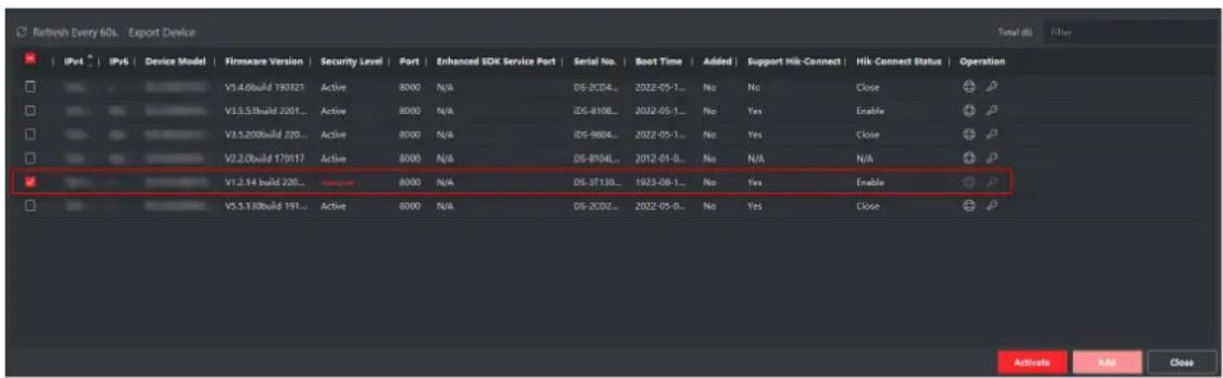
Figure 2-1 Online Device List
- Click Activate.
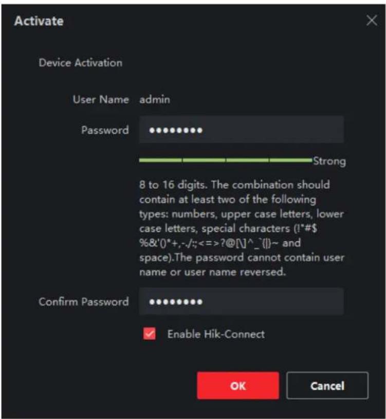
Figure 2-2 Activate Device
- Create a password in the password field, and confirm the password.

Caution
- The password strength of the device can be automatically checked. We highly recommend you change the password of your own choosing (using a minimum of 8 characters, including at least three kinds of the following categories: uppercase letters, lowercase letters, digits, and special characters) in order to increase the security of your product. And we recommend you change your password regularly, especially in the high security system. Changing the password monthly or weekly can better protect your product.
- Proper configuration of all passwords and other security settings is the responsibility of the installer and/or end-user.

Note
The password cannot contain "admin" or its reverse.
- Optional: Check Enable Hik-Connect if the device supports Hik-Connect service.
- Click OK.
2.2 Add Device
The client provides various device adding modes, including IP/domain, IP segment, Hik-Connect, ISUP, and HiDDNS. The client also supports importing multiple devices in a batch when a large number of devices are to be added. This section introduces only one mode, namely, adding a detected online device.
Steps
- Click Device Management → Device.
- Click Online Device.
The searched online devices are displayed in the online device list.
- Select an online device.
- Click Add.

Note
For the inactive device, you need to create a password for it before you can add the device properly. For detailed steps, please refer to Activate Device.
- Enter the required information.
Name
Enter a descriptive name for the device.
IP Address
Enter the device's IP address. The IP address of the device is obtained automatically in this adding mode.
Port
You can customize the port number. The port number of the device is obtained automatically in this adding mode.
User Name
By default, the user name is admin.
Password
Enter the device password.

Caution
- The password strength of the device can be automatically checked. We highly recommend you change the password of your own choosing (using a minimum of 8 characters, including at least three kinds of following categories: uppercase letters, lowercase letters, digits, and special characters) in order to increase the security of your product. And we
recommend you change your password regularly, especially in the high security system. Changing the password monthly or weekly can better protect your product.
- Proper configuration of all passwords and other security settings is the responsibility of the installer and/or end-user.
-
Optional: Check TLS to enable transmission encryption using TLS (Transport Layer Security) protocol for security purpose.
-
Check Synchronize Time to synchronize the device time with the PC running the client after adding the device to the client.
-
Optional: Check Import to Group to create a group by device name, and import all channels of the device to this group.
-
Click Add.
-
Optional: Perform the following operation(s).
| RemoteConfiguration | Click in theOperationcolumn to perform remote configuration for the corresponding device. |
| Device Status | Click in theOperationcolumn to view device status, including recording status, signal status, hardware status, etc. |
| Edit DeviceInformation | Click in theOperationcolumn to edit the device information, such as IP address, user name, and password. |
| Check Online User | Click in theOperationcolumn to check the online users who access the device. The user information includes user name, user type, user's IP address, and login time. |
| Refresh Click in theOperationcolumn to get the latest device information. | |
| Delete Device | Select one or multiple devices, and clickDeleteto delete the selected device(s) from the client. |
Chapter 3 Device Status
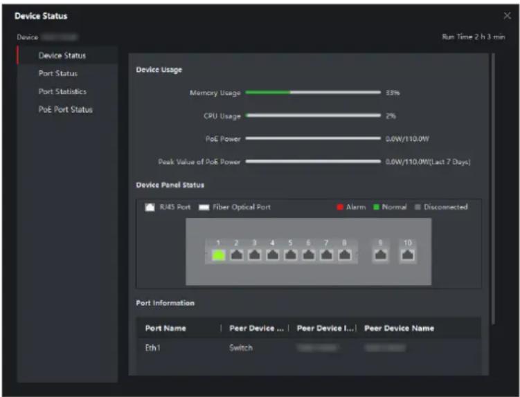
You can view the device status, port status, port statistics, and PoE port status.
Click Device → Operation →
bar
| Device | Usage | | --- | --- | | Memory Usage | 53% | | CPU Usage | 2% | | PoE Power | 0.0W/110.0W | | Peak Value of PoE Power | 0.0W/110.0W(Last 7 Days) |Figure 3-1 Device Status
Device Status
You can view the device usage, device panel status, and port information.
Port Status
You can view the bitrate, duplex mode, and flow control enabling status of each port.
Port Statistics
You can view the number of bytes sent or received, the number of packets sent or received, sending or receiving rate, and peak value of the sending or receiving rate. You can also set the interval at which port statistics are automatically refreshed, manually refresh port statistics, or clear port statistics.

Note
You can drag the scroll bar to view all statistics.
PoE Port Status
For devices that support PoE, you can view the PoE enabling status and output power of each RJ45 port.
Chapter 4 Topology Management
You can view and configure the topology between devices added.
4.1 Related Operations
Select an added device, and click → General Application → Topology.
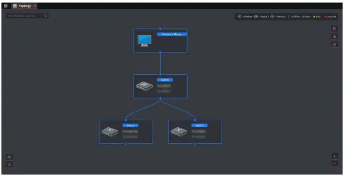
flowchart
graph TD
    A["Network Node"] --> B["Select"]
    B --> C["SELs"]
    B --> D["SELs"]
Figure 4-1 Topology Management
Interface Description
- In the upper left corner, you can enter a device name or IP address to search the device.
- In the upper right corner, you can view the meanings of different link icons and colors, select two devices to show the flash of signal transmission between them, and export or refresh the topology view.
- In the lower left corner, you can perform topology settings and view the tips.
- In the lower right corner, you can click the icons or scroll your mouse wheel to zoom in or out on the topology.

Note
If no topology is displayed when you access the topology interface for the first time, click a to refresh the topology view or get topology again.
Related Operations
| OperationDescription | |
| Double-click a device to view the device details. | You can view the type and IP address, usage, panel status, and port information of the device. |
| Double-click a link to view the link details. | You can view the transmission rate and devices at both ends of the link. |
| Right-click a device, and selectDevice Status, Event Handling, Remote Configuration, Edit Name, orSet as RootNodefrom the shortcut menu. | Device Status: You can jump to theDevice Statusinterface. For details, seeDevice Status. |
| Event Handling: You can view the event information, or clear events. | |
| Remote Configuration:·You can clickRemote Configuration → Basic Settingsto jump to the web page. For detailed operations, clickHelpin the upper right corner.·You can clickRemote Configuration → Advanced Functionto jump to theRemote Configurationinterface of the client. | |
| Edit Name: You can edit the device name. | |
| Set as Root Node: You can set the device as the root node. | |
| Click☐to export the topology view. | You can select the saving path and format, and export the topology view.NoteThe default format is PDF. |
| Click☐to show the transmission path. | You can select a network camera (IPC) and the current device to show the flash of signal transmission between them. |
4.2 Topology Settings
Steps
- Click in the lower left corner to edit topology settings.
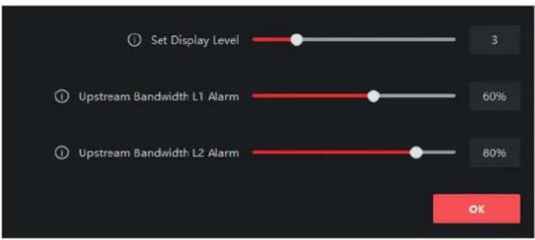
Figure 4-2 Topology Settings
Set Display Level
Set the topology display level. The value ranges from 1 to 10.

You need to manually refresh the topology view for the setting to take effect.
Upstream Bandwidth L1 Alarm
Set the L1 alarm threshold of upstream bandwidth. The value ranges from 1% to 100%.

The link will turn yellow (busy) when the upstream bandwidth exceeds this threshold.
Upstream Bandwidth L2 Alarm
Set the L2 alarm threshold of upstream bandwidth. The value ranges from 1% to 100%.

- The link will turn red (congested) when the upstream bandwidth exceeds this threshold.
- The L2 alarm threshold must be larger than the L1 alarm threshold.
2. Click OK.

After topology settings are changed, you can click to view the latest topology.
Chapter 5 Network Configuration
You can set network parameters as required.
i Note
- You can click Network → General to set device network parameters, or click Network → Advanced Settings and Network → Hik-Connect Settings to perform DNS and Hik-Connect configuration for troubleshooting if a device is displayed as offline when being added to the Hik-ProConnect app.
- DNS and Hik-Connect configuration is supported only when the client version is V2.8.1 or later.
General Settings
- Click → Advanced Function in the Operation column of the desired device.
- Click Remote Configuration → Network → General.
- Set the IPv4 address, subnet mask, MAC address, etc.
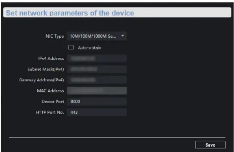
Figure 5-1 General Settings
i Note
After the IPv4 address is reset, the IP address of the device may not be in the same network segment as that of the PC running the client. As a result, device configuration and management cannot be performed. You are recommended to set a planned IP address for the device when activating it for the first time on SADP.
DNS Settings (Optional)
i Note
- If a device is successfully added to the Hik-ProConnect app, you do not need to configure the DNS IP addresses. The client automatically uses the preset DNS IP addresses.
-
If a device is displayed as offline when being added to the Hik-ProConnect app, the preset DNS IP addresses may be invalid. In this case, the DNS IP addresses need to be manually configured.
-
Click → Advanced Function in the Operation column of the desired device.
- Click Remote Configuration → Network → Advanced Settings.
- Configure DNS IP addresses in either of the following ways.
- Connect the PC to a network, open the Command Prompt window, and execute the ipconfig/all command to view the IP addresses of DNS servers. Then, enter the two IP addresses in the text boxes.
- Search for public DNS servers on the Internet, and enter the corresponding IP addresses in the text boxes.
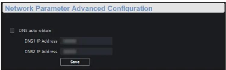
Figure 5-2 DNS Settings
i Note
- The function of automatically obtaining DNS IP addresses is available only after you check DNS auto-obtain in Network → Advanced Settings. Currently, DNS auto-obtain cannot be checked as this function is not supported.
- You are recommended to configure two DNS IP addresses simultaneously. If the first IP address is invalid, the client will automatically use the second one. If both IP addresses are invalid, please reconfigure DNS IP addresses. After configuration is complete, you can verify if the IP addresses are valid.
Hik-Connect Settings (Optional)
i Note
If a device is displayed as offline when being added to the Hik-ProConnect app, you need to perform Hik-Connect settings in addition to reconfiguring DNS IP addresses.
- Click → Advanced Function in the Operation column of the desired device.
-
Click Remote Configuration → Network → Hik-Connect Settings.
-
Check Enable Hik-Connect.
- Check View Operation Code.

Note
Make sure that the verification code entered for manually adding a device to the Hik-ProConnect app is the same as the operation code.
- Click Save.
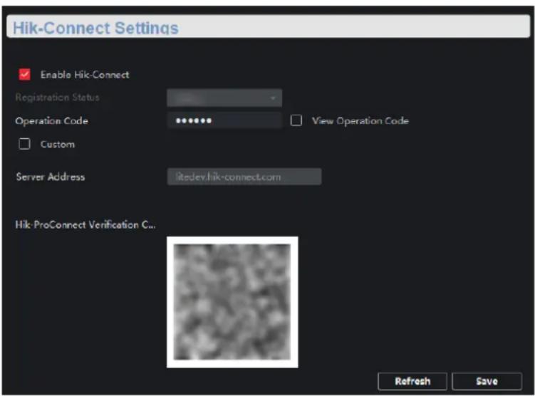
Figure 5-3 Hik-Connect Settings
Chapter 6 Device Configuration

Note
- You can click OK to make your device configurations take effect. Alternatively, to prevent invalid configurations caused by device powering-off, you can click Save All → Save All → Save to save all your configurations.
- Ports vary with different device models. The actual interfaces shall prevail.
6.1 Port Configuration
You can perform port attribute configuration, long-range port configuration, and PoE port configuration.
6.1.1 Attribute Configuration
Basic parameters can influence the working statuses of ports. You can configure the rates, duplex modes, and flow control enabling statuses of ports, and enable or disable ports as required.
Click Remote Configuration → Port Configuration → Attribute Configuration.
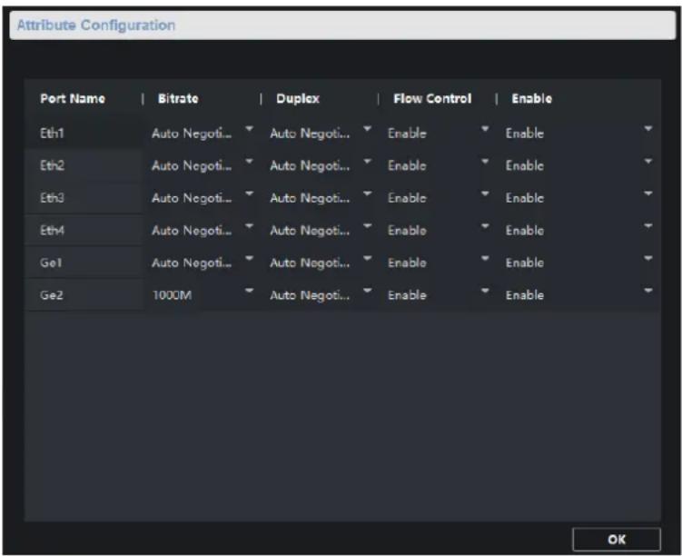
Figure 6-1 Attribute Configuration
Bitrate
Data transmission rate of a port. The value can be auto negotiation, 10 Mbps, 100 Mbps, or 1000 Mbps. The default value is Auto Negotiation. Configurable rates vary with different ports.
Duplex
Duplex mode of a port. The value can be auto negotiation or full duplex. The default value is Auto Negotiation. Configurable modes vary with different ports.
Flow Control
Flow control enabling status of a port. Enabling flow control can prevent data loss during data transmission. The default value is Enable.
Enable
Enabling status of a port. After a port is disabled, it stops data transmission, but supplies power to another device.

Note
The rates, duplex modes, and flow control enabling statuses of ports in an aggregation group must be the same.
6.1.2 Long-Range Port Configuration
After the long-range mode is enabled for a port, the transmission distance of the port can reach 300 meters, and the rate is forcibly configured as 10 Mbps. After the long-range mode is disabled, the rate of the port is restored to auto-negotiation.
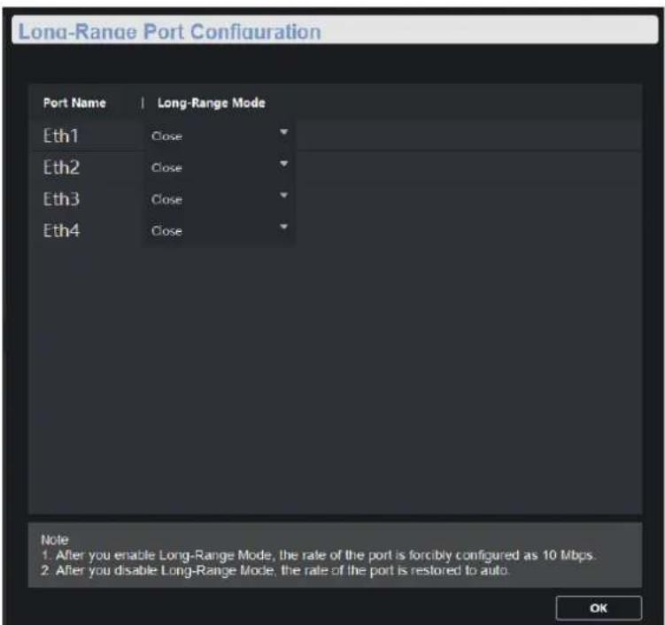
Figure 6-2 Long-Range Port Configuration
6.1.3 PoE Port Configuration
You can enable the PoE function of a port to supply power to a powered device (PD).

Note
Enabling or disabling PoE does not affect data transmission of a port.
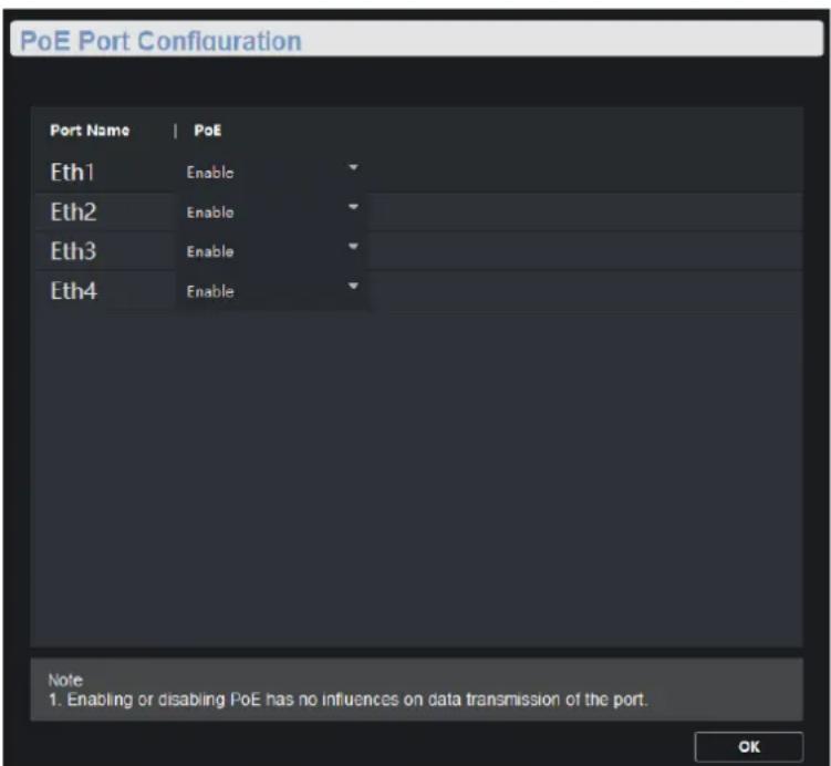
Figure 6-3 PoE Port Configuration

Note
PoE port configuration is only allowed for devices that support PoE.
6.2 Link Aggregation Configuration
Link aggregation is a mechanism used to aggregate physical ports to create a logical entity called link bundle. The benefits of link aggregation include increased bandwidth, load balancing, and higher reliability.
Steps
- Click → Advanced Function in the Operation column of the desired device.
- Click Link Aggregation → Link Aggregation Configuration → Load Balancing Mode.

Note
The load balancing mode is set to Source and Destination MAC by default, and is not configurable.
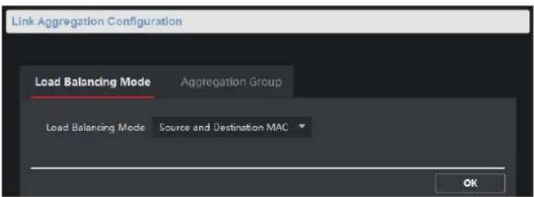
Figure 6-4 Load Balancing Mode Configuration
Source and Destination MAC
Load balancing is performed based on source and destination MAC addresses on all the packets.
- Click Link Aggregation → Link Aggregation Configuration → Aggregation Group.

Note
Only gigabit ports can be added to an aggregation group for link aggregation.
- Click Add.
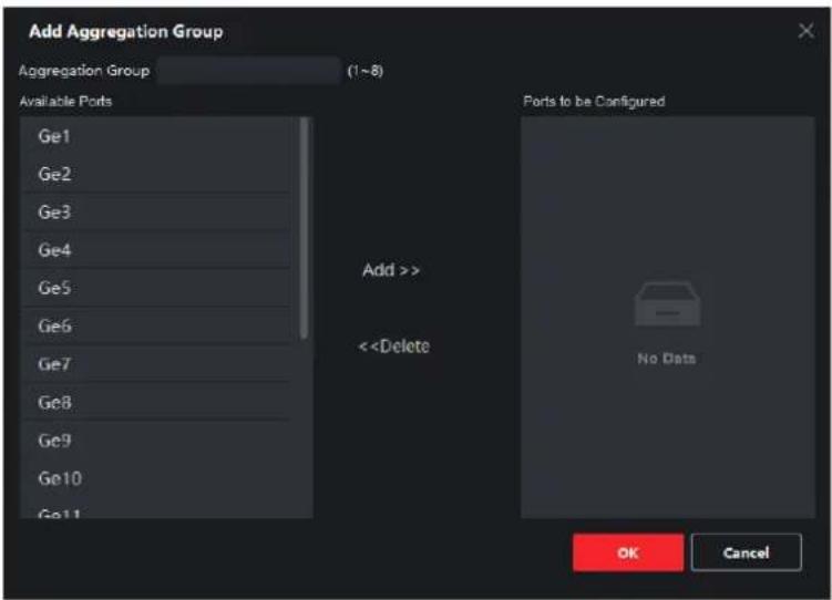
7.2 User Management
Only one admin user is allowed. You cannot add a user or delete the admin user, but can edit the password and permissions of the admin user.Steps
1. Click → Advanced Function in the Operation column of the desired device. 2. Click System → User.  Figure 7-2 User Management 3. Select the admin user. 4. Click Edit to edit the password and permissions of the user.  Figure 7-3 User Parameters Note
- 8 to 16 characters allowed for a password, including at least 2 of the following types: digits, lowercase letters, uppercase letters, and special characters. The password strength of the device can be automatically checked. We highly recommend you change your password regularly in order to increase the security of your product. - Currently, editing user permissions is not supported.7.3 Device Maintenance
You can restart your device, restore the defaults, import and export configuration files, or upload an upgrade file to upgrade your device.Steps
1. Click → Advanced Function in the Operation column of the desired device. 2. Click System → System Maintenance.  Figure 7-4 System Maintenance 3. Click a button or icon to realize the desired function. - Click Reboot to remotely restart the device. - Click Restore Default Settings to restore all parameters except network parameters and user parameters to factory settings. - Click Restore All to restore all parameters to factory settings. After restoration, the device needs to be reactivated. - Click Import Configuration File, select a configuration file, and enter the file encryption password to import the configuration file. After import, the device will be automatically restarted. - Click Export Configuration File, set the file encryption password, and select a saving path to export the configuration file. - Click next to Select File, upload an upgrade file, and click Upgrade to upgrade the device. The upgrading progress is displayed in the progress bar.  If upgrading failed or the device cannot function, please contact our technical engineers.7.4 Log Management
You can search and export system operation logs for backup.Steps
1. Click → Advanced Function in the Operation column of the desired device. 2. Click System → Log Query. 3. Set search conditions.  Figure 7-5 Set Search ConditionsSearch Mode
By Type, By Time, By Type and Time, or All can be selected.Major Type
Operation, Event, or All can be selected. If you select the search mode as By Time, the major type cannot be set.Minor Type
Minor types vary with different major types. If you select the search mode as By Time, the minor type cannot be set.Start Time
Start time of a log querying period. Logs generated during this period are to be queried. If you select the search mode as By Type, the start time cannot be set.End Time
End time of a log querying period. Logs generated during this period are to be queried. If you select the search mode as By Type, the start time cannot be set.4. Click Search.
 Figure 7-6 Searched Logs 5. Click Backup, and select a backup path. 6. Click Backup to save a .csv or .xml file.  Figure 7-7 Log Backup7.5 Security Configuration
If an IP address is locked because you enter an incorrect password for several consecutive times, you can use an unlocked IP address to log in to the client as the admin user from the PC to unlock the locked IP address.Steps
Note
If you need to unlock the locked IP address immediately, contact the administrator. 1. Click → Advanced Function in the Operation column of the desired device. 2. Click System → Security. 3. Unlock the IP address(es). - Click the unlock icon to unlock a single locked IP address. - Click Unlock All to unlock all locked IP addresses. Note
- Up to 5 password attempts are allowed for ordinary users, and 7 for the admin user. - If the IP address is locked, use a new IP address to log in to the client as the admin user again, and unlock the locked IP address.7.6 Time Configuration
You can set or synchronize the device time.Steps
1. Click → Advanced Function in the Operation column of the desired device. 2. Click System → Time.  Figure 7-8 Time Settings 3. Select a time zone, and set the device time. - Automatic time synchronization: Check Enable NTP, and set the server address, NTP port number, and synchronization interval to synchronize the device time with the NTP server time at the specified interval. - Manual time synchronization: Click Synchronization under SDK Synchronization to synchronize the device time with the PC time. 4. Click Save.Chapter 8 Appendix
8.1 Communication Matrix
Please scan the QR code below to view the communication matrix document.  Figure 8-1 Communication Matrix8.2 Device Command
Please scan the QR code below to view the device command document.  Figure 8-2 Device Command  See Far, Go Further- About this Manual
- Trademarks
- Disclaimer
- Preface
- Applicable Models
- Symbol Conventions
- Safety Instructions
- Danger
- Caution
- Contents
- Chapter 1 Product Introduction .... 1
- Chapter 2 Device Management .... 2
- Chapter 3 Device Status .... 6
- Chapter 4 Topology Management .... 7
- Chapter 5 Network Configuration ...... 10
- Chapter 6 Device Configuration .... 13
- Chapter 7 System Configuration .... 19
- Chapter 8 Appendix ...... 25
- Chapter 1 Product Introduction
- Chapter 2 Device Management
- Note
- Activate Device
- Before You Start
- Steps
- Add Device
- Name
- IP Address
- Port
- User Name
- Password
- Chapter 3 Device Status
- Device Status
- Port Status
- Port Statistics
- PoE Port Status
- Chapter 4 Topology Management
- Related Operations
- Interface Description
- Topology Settings
- Set Display Level
- Upstream Bandwidth L1 Alarm
- Upstream Bandwidth L2 Alarm
- Click OK.
- Chapter 5 Network Configuration
- i Note
- General Settings
- DNS Settings (Optional)
- Hik-Connect Settings (Optional)
- Chapter 6 Device Configuration
- Port Configuration
- Attribute Configuration
- Duplex
- Flow Control
- Enable
- Long-Range Port Configuration
- PoE Port Configuration
- Link Aggregation Configuration
- Source and Destination MAC
- Chapter 7 System Configuration
- Device Information
- User Management
- Device Maintenance
- Log Management
- Search Mode
- Major Type
- Minor Type
- Start Time
- End Time
- Click Search.
- Security Configuration
- Time Configuration
- Chapter 8 Appendix
- Communication Matrix
- Device Command
Brand : Hikvision
Model : DS-3E1552P-SI
Category : Network switch