
DS-3E2510P - Network switch Hikvision - Free user manual and instructions
Find the device manual for free DS-3E2510P Hikvision in PDF.


| Product Type | Managed PoE+ Network Switch |
| Brand | Hikvision |
| Model | DS-3E2510P |
| Ports | 8 x Gigabit PoE+ (10/100/1000) + 2 x Gigabit SFP |
| PoE Budget | 240W |
| Power Input | 100-240V AC, 50/60Hz |
| Power Consumption | ≤ 300W |
| Dimensions (W x D x H) | 440 x 200 x 44 mm |
| Weight | 3.5 kg |
| Management | Web GUI, SNMP, CLI, Telnet, SSH |
| Key Features | VLAN, QoS, Link Aggregation, Port Mirroring, STP/RSTP, IGMP Snooping, ACL |
| Fan | Smart fan with speed control |
| Operating Temperature | 0°C to 50°C |
| Operating Humidity | 5% to 95% (non-condensing) |
| Certifications | CE, FCC, RoHS |
| Cleaning & Maintenance | Disconnect power, clean with dry soft cloth, avoid liquids |
| Safety | Ensure proper grounding, avoid overloading, keep ventilation clear |
| Spare Parts & Repairability | No user-serviceable parts; contact authorized service center |
| General Information | Rack-mountable 19"; fan noise < 40 dB(A) @ 25°C |
Frequently Asked Questions - DS-3E2510P Hikvision
User questions about DS-3E2510P Hikvision
0 question about this device. Answer the ones you know or ask your own.
Ask a new question about this device
Download the instructions for your Network switch in PDF format for free! Find your manual DS-3E2510P - Hikvision and take your electronic device back in hand. On this page are published all the documents necessary for the use of your device. DS-3E2510P by Hikvision.
USER MANUAL DS-3E2510P Hikvision
8/24 Series Ethernet Switch
User Manual
UD03706B
User Manual
COPYRIGHT ©2016 Hangzhou Hikvision Digital Technology Co., Ltd.
ALL RIGHTS RESERVED.
Any and all information, including, among others, wordings, pictures, graphs are the properties of Hangzhou Hikvision Digital Technology Co., Ltd. or its subsidiaries (hereinafter referred to be "Hikvision"). This user manual (hereinafter referred to be "the Manual") cannot be reproduced, changed, translated, or distributed, partially or wholly, by any means, without the prior written permission of Hikvision. Unless otherwise stipulated, Hikvision does not make any warranties, guarantees or representations, express or implied, regarding to the Manual.
About this Manual
This Manual is applicable to DS-C10S-SXXT Series Video Wall Controller.
The Manual includes instructions for using and managing the product. Pictures, charts, images and all other information hereinafter are for description and explanation only.
The information contained in the Manual is subject to change, without notice, due to firmware updates or other reasons. Please find the latest version in the company website (http://overseas.hikvision.com/en/).
Please use this user manual under the guidance of professionals.
Trademarks Acknowledgement
HIKVISION
and other Hikvision's trademarks and logos are the properties of Hikvision
in various jurisdictions. Other trademarks and logos mentioned below are the properties of their respective owners.
Legal Disclaimer
TO THE MAXIMUM EXTENT PERMITTED BY APPLICABLE LAW, THE PRODUCT DESCRIBED, WITH ITS HARDWARE, SOFTWARE AND FIRMWARE, IS PROVIDED "AS IS", WITH ALL FAULTS AND ERRORS, AND HIKVISION MAKES NO WARRANTIES, EXPRESS OR IMPLIED, INCLUDING WITHOUT LIMITATION, MERCHANTABILITY, SATISFACTORY QUALITY, FITNESS FOR A PARTICULAR PURPOSE, AND NON-INFRINGEMENT OF THIRD PARTY. IN NO EVENT WILL HIKVISION, ITS DIRECTORS, OFFICERS, EMPLOYEES, OR AGENTS BE LIABLE TO YOU FOR ANY SPECIAL, CONSEQUENTIAL, INCIDENTAL, OR INDIRECT DAMAGES, INCLUDING, AMONG OTHERS, DAMAGES FOR LOSS OF BUSINESS PROFITS, BUSINESS INTERRUPTION, OR LOSS OF DATA OR DOCUMENTATION, IN CONNECTION WITH THE USE OF THIS PRODUCT, EVEN IF HIKVISION HAS BEEN ADVISED OF THE POSSIBILITY OF SUCH DAMAGES.
REGARDING TO THE PRODUCT WITH INTERNET ACCESS, THE USE OF PRODUCT SHALL BE WHOLLY AT YOUR OWN RISKS. HIKVISION SHALL NOT TAKE ANY RESPONSIBILITES FOR ABNORMAL OPERATION, PRIVACY LEAKAGE OR OTHER DAMAGES RESULTING FROM CYBER ATTACK, HACKER ATTACK, VIRUS INSPECTION, OR OTHER INTERNET SECURITY RISKS; HOWEVER, HIKVISION WILL PROVIDE TIMELY TECHNICAL SUPPORT IF REQUIRED.
SURVEILLANCE LAWS VARY BY JURISDICTION. PLEASE CHECK ALL RELEVANT LAWS IN YOUR JURISDICTION BEFORE USING THIS PRODUCT IN ORDER TO ENSURE THAT YOUR USE CONFORMS THE APPLICABLE LAW. HIKVISION SHALL NOT BE LIABLE IN THE EVENT THAT THIS PRODUCT IS USED WITH ILLEGITIMATE PURPOSES.
IN THE EVENT OF ANY CONFLICTS BETWEEN THIS MANUAL AND THE APPLICABLE LAW, THE LATER PREVAILS.
Regulatory Information
FCC Information
Please take attention that changes or modification not expressly approved by the party responsible for compliance could void the user's authority to operate the equipment.
FCC compliance: This equipment has been tested and found to comply with the limits for a Class A digital device, pursuant to part 15 of the FCC Rules. These limits are designed to provide reasonable protection against harmful interference when the equipment is operated in a commercial environment. This equipment generates, uses, and can radiate radio frequency energy and, if not installed and used in accordance with the instruction manual, may cause harmful interference to radio communications. Operation of this equipment in a residential area is likely to cause harmful interference in which case the user will be required to correct the interference at his own expense.
FCC Conditions
This device complies with part 15 of the FCC Rules. Operation is subject to the following two conditions:
- This device may not cause harmful interference.
- This device must accept any interference received, including interference that may cause undesired operation.
EU Conformity Statement
CE
This product and - if applicable - the supplied accessories too are marked with "CE" and comply therefore with the applicable harmonized European standards listed under the EMC Directive 2014/30/EU, the LVD Directive 2014/35/EU, the RoHS Directive 2011/65/EU.

2012/19/EU (WEEE directive): Products marked with this symbol cannot be disposed of as unsorted municipal waste in the European Union. For proper recycling, return this product to your local supplier upon the purchase of equivalent new equipment, or dispose of it at designated collection points. For more information see: www.recyclethis.info

2006/66/EC (battery directive): This product contains a battery that cannot be disposed of as unsorted municipal waste in the European Union. See the product documentation for specific battery information. The battery is marked with this symbol, which may include lettering to indicate cadmium (Cd), lead (Pb), or mercury (Hg). For proper recycling, return the battery to your supplier or to a designated collection point. For more information see: www.recyclethis.info
Industry Canada ICES-003 Compliance
This device meets the CAN ICES-3 (A)/NMB-3(A) standards requirements.
Preparing for installation
The HIKVISION 8/24 Series Ethernet Switch includes the following models:
| Model | Name |
| 8 | Ethernet Switch |
| 24 | Ethernet Switch |
Symbol Conventions
The symbols that may be found in this document are defined as follows.
| Symbol | Description |
 | Provides additional information to emphasize or supplement important points of the main text. |
 | Indicates a potentially hazardous situation, which if not avoided, could result in equipment damage, data loss, performance degradation, or unexpected results. |
 | Indicates a hazard with a high level of risk, which if not avoided, will result in death or serious injury. |
Table of Contents
Chapter 1 8/24 Switch Overview ...... 1
1.1 Standard Configuration .... 1
1.2 Characteristic Parameters of 8/24 switch....4
Chapter 2 Installation Preparation....5
2.1 Cautions ...... 5
2.2 Safety Advice....5
2.2.1 Safety Principles....5
2.2.2 Safety Notices .... 5
2.2.3 Safety Principles for Live Working....5
2.2.4 Electrostatic Discharge Damage Prevention 6
2.3 Requirements for Common Locations 6
2.3.1 Environment 6
2.3.2 Location Configuration Prevention 7
2.3.3 Cabinet Configuration....7
2.3.4 Power Requirements 7
2.4 Installation Tools and Device 7
Chapter 3 Installing the 8/24 Switch....8
3.1 Installation Procedures of 8/24 switch....8
3.2 Installing the Chassis of 8/24 switch 8
3.2.1 Installing the Chassis on the Desk 8
3.2.2 Installing the Chassis on the Cabinet....8
3.3 Connecting the Port 9
3.3.1 Connecting the Console Port 9
3.3.2 Connecting the SFP Ports 11
3.3.3 Connecting Gigabit Ethernet TX Ports 11
3.4 Checkup after Installation....13
Chapter 4 8/24 switch Maintenance .... 14
4.1 Opening the Chassis 14
4.2 Closing the Chassis....14
Chapter 5 Hardware Fault Analysis....16
5.1 Fault Separation 16
5.1.1 Faults Relative with Power and Cooling System 16
5.1.2 Faults Relative with Port, Cable and Connection 16
5.2 LED Description 16
Chapter 6 Specifications ....18
Chapter 1 8/24 Switch Overview
The document describes the characteristics and parameters of 8/24 and gives an overview of 8/24 switch.
1.1 Standard Configuration
8/24 switch has three parts: 8 IEEE802.3af/at gigabit Ethernet TX ports, 2 gigabit Ethernet SFP ports and 1 Console port. See the following table:
Table 1-1 Attributes of necessary ports
| Port | Features |
| Gigabit PoE ports | TX port: a rate of 10/100/1000M auto-adaptation, cable MDI/MDIX auto-identification, UTP(RJ45) port |
| Gigabit Ethernet optical ports | Optical port: 100/1000M SFP port, with LINK/ ACT indicators |
| Console port | A rate of 9600bps, RJ45 interface |
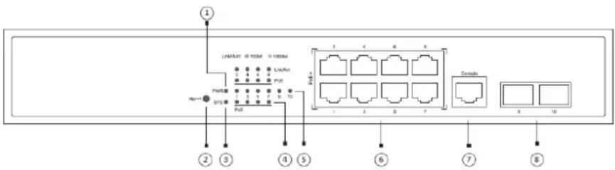
Figure 1-1 Front template of the 8 switch
Table 1-2 Parts at the front template of the 8 switch
| No. | Abbrev. | Name | Remarks |
| 1 | PWR | power indicator | If the switch is powered on, the indicator is on. |
| 2 | RESET | RESET | Resume to the default setting. |
| 3 | SYS | System indicator | If the indicator is always on, the system is started up.If the indicator flickers, the system works normally. |
| 4 | PoE | PoE indicator corresponding to each port | If the indicator is always on, the PoE works normally.If the indicator is off, the PoE does not work. |
| 5 | Lnk/Act | Lnk/Act indicator corresponding to each port | Green indicator is on: 10/100M is transmitted;Red indicator is on: 1000M is transmitted;No indicator is on: no signal is transmitted. |
| 6 | / | 8 RJ45 interfaces | Realizes the PoE function and forwards 10/100/1000M Ethernet electrical signals |
| 7 | Console | Console | Manages the switch locally. |
| 8 | / | 2 SFP ports | Realizes the forward of gigabit Ethernet optical signals. |

Figure 1-2 Front template of the 24 switch
Table 1-3 Parts at the front template of the 24 switch
| No. | Abbrev. | Name | Description |
| 1 | CONSOLE | Console port | Manages the switch locally. |
| 2 | SYS | System indicator | If the indicator is always on, the system is being started.If the indicator flickers, the system works normally. |
| 3 | PWR | Power indicator | If the switch is powered on, the indicator is on. |
| 4 | Link/ACT | LINK/ACT indicator of each port | If the indicator is on in green: 10/100M,If the indicator is on in red: 1000MIf the indicator is not on: no signal is transmitted. |
| 5 | POE | POE indicator | If the indicator is always on: POE works normally;If the indicator is not on, POE does not work. |
| 6 | Reset | Reset switch | Return to the factory setting. |
| 7 | / | 24 gigabit RJ45 ports | Forwards the 10/100M/1000M Ethernet electric signals and provides with POE functions. |
| 6 | / | 4 SFP ports | Forwards 1000M Ethernet optical signals. |
Besides, 8/24 switch provides with a grounding column, a power socket, and a silent fan.
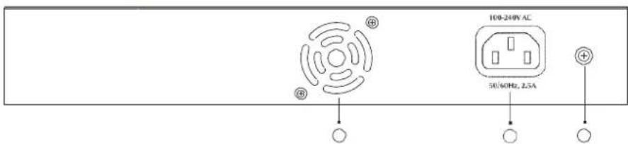
Figure 1-3 Back template of the 8 switch
Table 1-4 Parts at the rear template of the 8 switch
| No. | Abbrev. | Name | Remarks |
| 1 | / | Fan | / |
| 2 | / | AC power socket | 100~240V AC |
| 3 | / | The grounding column | The grounding must be fine. |

Figure 1-4 Back template of the 24 switch
Table 1-5 Parts at the rear template of the 24 switch
| No. | Abbrev. | Name | Description |
| 1 | / | Grounding column | The grounding must be fine. |
| 2 | / | AC power socket | 100~240V AC |
1.2 Characteristic Parameters of 8/24 switch
| Protocol standard | Supported standard | IEEE 802.1d Spanning Tree ProtocolIEEE 802.1p Class of ServiceIEEE 802.1q tagged VLANIEEE 802.3x Flow controlIEEE 802.3ad Link aggregationIEEE 802.3af Power via Media Dependent InterfaceIEEE 802.3at DTE Power Enhancements |
| IP routing protocol standard | RFC 1058 RIPRFC 1723 RIP v2 | |
| Network management standard | RFC 1157 SNMP v1/v2RFC 1213 MIB IIRFC 1757 RMON 1,2,3,9 | |
| Standard configuration | 2/4 Gigabit Ethernet SFP ports1 Console port8/24 Gigabit Ethernet TX ports | |
| Dimensions (W×H×D) (mm) | 280×179×45 / 440×232×45 | |
| Operating temperature/humidity | 0°C to 45°C; 5%-95% non-condensing | |
| Storage temperature/humidity | -20°C to 70°C; 5%-95% non-condensing | |
| Power supply | Input voltage: AC100-240V; Input frequency: 50Hz±10% |
Chapter 2 Installation Preparation
2.1 Cautions
Similar to other electronic products, the semiconductor chip easily gets damaged if you power on and off abruptly and frequently. To restart up the switch of 8/24, you have to open the power on-off three or five seconds after the power is cut off.
Avoid severe collision or falling down from the height to protect the parts in the switch.
Use correct outside ports to connect the switch of 8/24. Do not insert the Ethernet plug into the console port (RJ45 8-line socket). Similarly, do not insert the console cable into the console port (RJ45 8-line socket).
Note:
1) When you plug or dial out the power line, keep the power line horizontal with the power socket.
2) When the lifetime of our products ends, handle them according to national laws and regulations, or send these products to our company for collective processing.
2.2 Safety Advice
2.2.1 Safety Principles
- Keep dustless and clean during or after the installation.
- Put the cover at the safe place.
- Put tools at the right place where they are not easily falling down.
- Put on relatively tight clothes, fasten the tie or scarf well and roll up the sleeve, avoiding stumbling the chassis.
- Put on the protective glasses if the environment may cause damage to your eyes.
- Avoid incorrect operations that may cause damage to human or devices.
2.2.2 Safety Notices
The safety notices mentioned here means that improper operation may lead to body damage.
- Read the installation guide carefully before you operate the system.
- Only professionals are allowed to install or replace the switch.
- Please cut off the direct-current connection when you operate the hull or work near the power supply.
- The final configuration of products must comply with relative national laws and regulations.
2.2.3 Safety Principles for Live Working
When you work under electricity, following the following principles:
- Put off ornaments, such as ring, necklace, watch and bracelet, before you operate under live working. When metal articles connect the power to the ground, short circuit happens and components may be damaged.
- Please cut off the direct-current connection when you operate the hull or work near the power supply.
- When the power is on, do not touch the power.
- Correctly connect the device and the power socket.
- Only professionals are allowed to operate and maintain the device.
- Read the installation guide carefully before the system is powered on.
Note:
1) Check potential dangers, such as the humid floor, ungrounded extensible power line and tatty power line.
2) Install the emergent on-off at the working room for turning off the power when trouble happens.
3) Plug off the power line before installing or uninstalling the machine box or working beside the power.
4) Do not work alone if potential dangers exist.
5) Cut off the power before checkout.
6) If trouble happens, take the following measures:
A. Cut off the system's power.
B. Alarm.
C. Take proper measures to help persons who are hit by the disaster. Artificial respiration is needed if necessary.
D. Seek for medical help, or judge the loss and seek for available help.
2.2.4 Electrostatic Discharge Damage Prevention
Electrostatic discharge may damage devices and circuits. Improper treatment may cause the switch to malfunction completely or discontinuously.
Move or locate the devices according to the measures of electrostatic discharge prevention, ensuring the machine box connects the ground. Another measure is to wear the static-proof hand ring. If there is no hand ring, use the metal clip with the metal cable to clip the unpainted metal part of the machine box. In this case, the static is discharged to the ground through the metal cable of the clip. You can also discharge the static to the ground through your body.
2.3 Requirements for Common Locations
This part describes the requirements for the installation locations.
2.3.1 Environment
8/24 switch adopts the wall-mounted installation mode. The switch has no fan, so an environment with good ventilation is needed for the heat cooling of the switch.
For location planning and device locating, refer to section 2.3.2 "Location Configuration Prevention".
2.3.2 Location Configuration Prevention
The following preventive measures assist you to design the proper environment for the switch.
- Make sure that the workshop is well-ventilated, the heat of TX devices is well-discharged and sufficient air circulation is provided for device cooling.
- Put the chassis at the place where cool air can blow off the heat inside the chassis. Make sure the chassis is sealed because the opened chassis will reverse the cool air flow.
2.3.3 Cabinet Configuration
The following content assists you to make a proper cabinet configuration:
- Each device on the cabinet gives off heat when it runs. Therefore, the sealed cabinet must have the heat-discharge outlet and the cooling fan. Do not put the devices too close, avoiding bad ventilation.
- When you install the chassis at the open cabinet, prevent the frame of the cabinet from blocking the airway of the chassis.
- Ensure that nice ventilation is provided for the devices installed at the bottom of the cabinet.
- The clapboard separates exhaust gas and inflow air, and boost the cool air to flow in the chassis. The best location of the clapboard is decided by the air flow mode in the chassis, which can be obtained through different location tests.
2.3.4 Power Requirements
Make sure that the power supply has nice grounding and the power at the input side of the switch is reliable. The voltage control can be installed if necessary. At least a 240 V, 10A fuse or a breaker is provided in the phase line if you prepare the short-circuit prevention measures for a building.
Caution:
If the power supply system does not have good grounding, or the input power disturbs too much and excessive pulses exist, the error code rate of communication devices increases and even the hardware system will be damaged.
2.4 Installation Tools and Device
The tools and devices to install the 8/24 switch are not provided by the 8/24 switch. You yourself need to prepare them. The following are the tools and devices needed for the typical installation of the 8/24 switch:
- Screwdriver
- Static armguard
- Bolt
- Ethernet cable
● Other Ethernet terminal devices - Control terminal
Chapter 3 Installing the 8/24 Switch
Caution:
Only professionals are allowed to install or replace the devices of the switch.
3.1 Installation Procedures of 8/24 switch
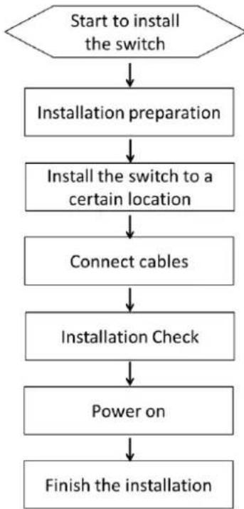
flowchart
graph TD
    A["Start to install the switch"] --> B["Installation preparation"]
    B --> C["Install the switch to a certain location"]
    C --> D["Connect cables"]
    D --> E["Installation Check"]
    E --> F["Power on"]
    F --> G["Finish the installation"]
3.2 Installing the Chassis of 8/24 switch
The chassis of the switch can be put on the desk or fixed to the cabinet. Your network installation requirements can be met if you conduct the operations according to the following procedure. It can be described in the following two parts:
● Installing the Chassis on the Desk
● Installing the Chassis on the Cabinet
3.2.1 Installing the Chassis on the Desk
The 8/24 switch can be directly put on the smooth and safe desk.
Note:
Do not put things weighing 4.5 kg or over 4.5 kg on the top of the switch.
3.2.2 Installing the Chassis on the Cabinet
The chassis of the switch is fixed to the cabinet through the fixing mouth. When operation it is enough to fix the back template of the switch through the fixing mouth to the cabinet.
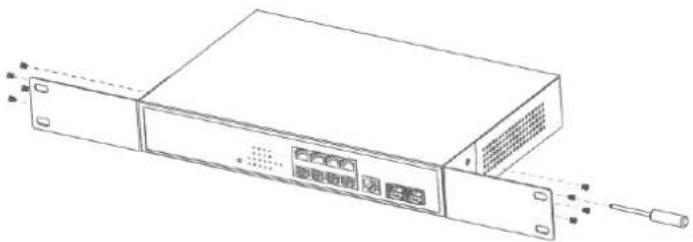
natural_image
Line drawing of a server rack unit with ports and connectors (no text or symbols)Figure 3-1 Fixing the machine box of the switch
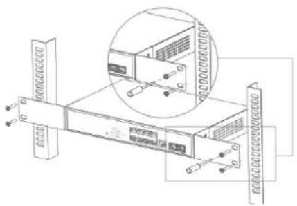
After the brackets are installed, install the switch on the cabinet. See Figure 3-2.
natural_image
Technical line drawing of a server rack with an inset showing internal components (no text or symbols)Figure 3-2 Installing the switch on the cabinet
3.3 Connecting the Port
3.3.1 Connecting the Console Port
The switch of 8/24 switch has a Console port. The rate of the console port is a value of 1200bps—115200bps. It has a standard RJ45 plug. After you connect the console port to the serial port of PC through a console cable, you can configure and monitor the switch of 8/24 by running a terminal emulation software, such as super Windows terminal. The cable is provided according to the host. The communication parameters of the terminal serial port can be set to a rate of 9600bps, eight data bits, one stop bit, no sum check bit and traffic control.
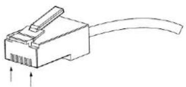
The RJ45 connector of the console port is shown in the following figure. The RJ45 plug corresponds to the RJ45 socket, whose pins can be aligned from left to right with the value from 1 to 8.
natural_image
Line drawing of a USB connector with a cable and two arrows indicating direction (no text or symbols)Figure 3-3 RJ-45 connector of the console port
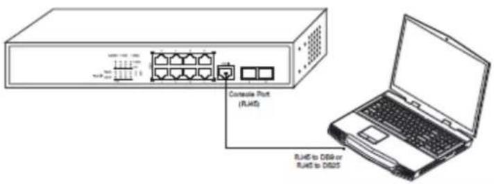
Figure 3-4 Connecting the console port of 8/24 and computer
Table 3-1 Definition of the pins of the console port
| No. | Name | Abbreviation | Remarks |
| 1 | Carrier Detecting | CD | No connect |
| 2 | Data receiving | RXD | Input |
| 3 | Data-line device ready | DSR | No connect |
| 4 | Data transmitting | TXD | Output |
| 5 | Transmission requesting | RTS | No connect |
| 6 | Response transmitting | CTS | No connect |
| 7 | Data terminal ready | DTR | No connect |
| 8 | Signal ground | SG | GND |
Note:
Because the console port of 8/24 switch bears no flow control, you need to set Data flow control to none when using a superior terminal to manage 8/24 switch configurations, or the single-pass problem will arise from the superior terminal.
The cable is used to connect the console port of the 8/24 switch and the outside console terminal device. One end of the cable is a 8-pin RJ45 plug and the other end is a 25-hole plug (DB25) and a 9-hole plug (DB9). The RJ45 plug is put into the socket of the console port on the 8/24 switch. DB25 or DB9 is applied according to the requirement of the terminal serial port. The inner line connection in the cable is shown in Figure 3-5.
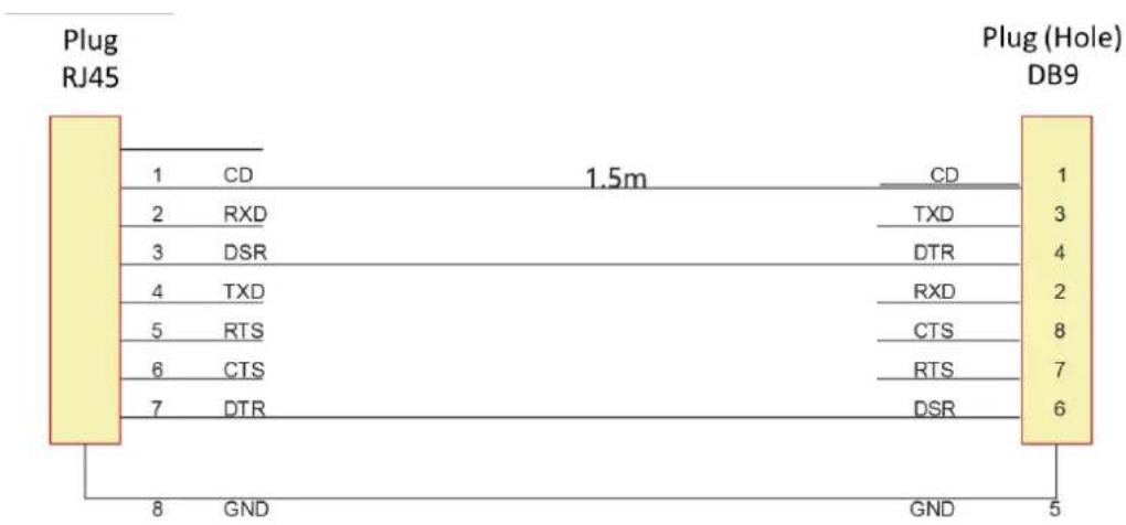
Figure 3-5 Cable connection at the console port
3.3.2 Connecting the SFP Ports
8/24 switch provides 2/4 gigabit SFP optical ports. Each port corresponds to one indicator respectively, which is used for indicating the port Link/ACT state. When the indicator is always on, the link is normal; when it flickers, the data receives and forwards. To use the optical port, you need connect it to the SFP optical module, and then to other Ethernet terminal devices through an optical fiber.
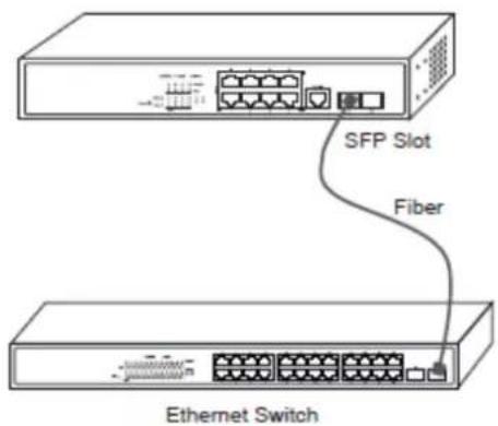
Figure 3-6 Connecting the SFP ports and other Ethernet terminals
3.3.3 Connecting Gigabit Ethernet TX Ports
The 8/24 switch has 8/24 10/100/1000 Base-TX ports. Each port has one indicator, which indicates the state of Link/ACT. If the indicator is always on, the port is linked up; if the indicator flickers, the data is transmitted on the port. The numbering order of the pins in the UTP port is the same as the console port.
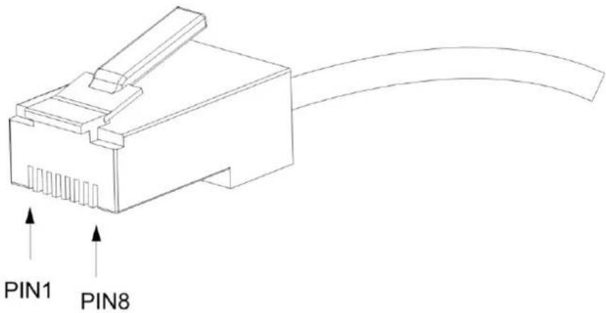
Figure 3-7 RJ-45 connector of the console port
Because 8/24 switch 10/100/1000 Base-TX ports of 8/24 support the MDI/MDIX auto-identification of the cable, 8/24 can adopt five classes of direct-through/cross network cables when it connects other Ethernet terminals.
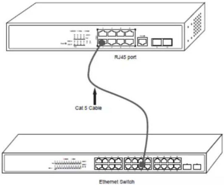
Figure 3-8 Connecting Base-T ports and other Ethernet terminal
Table 3-3 Definition of the pins of the 1000M RJ45 port
| No. | Pin name | Symbol | Note |
| 1 | Sending the normal phase of the data | TXD1+ | Output |
| 2 | Sending the paraphase of the data | TXD1- | Output |
| 3 | Receiving the normal phase of the data | RXD1+ | Input |
| 4 | Sending the normal phase of the data | TXD2+ | Output |
| 5 | Sending the paraphase of the data | TXD2- | Output |
| 6 | Receiving the paraphase of the data | RXD1- | Input |
| 7 | Receiving the paraphase of the data | RXD2+ | Input |
| 8 | Sending the paraphase of the data | RXD1- | Input |
The direct-through or cross network cable has the function of auto-identification, so the five classes of direct-through/cross network cables can be used to connect other Ethernet devices.
3.4 Checkup after Installation
Before feeding power to start the switch, perform the following checkups after the switch is installed:
- If the switch is installed on the DIN rail, check whether the installation is strong.
If the switch is installed on the desk, check whether there is enough space for the switch to discharge its heat and whether the desk is stable. - Check whether the connected power supply meets the power requirements of the switch.
- Check whether the grounding line of 8/24 switch is correctly connected.
- Check whether 8/24 switch is correctly connected to other terminal devices.
Chapter 4 8/24 switch Maintenance
Caution:
1) Before opening the chassis, make sure that you have released the static you carried and then turn off the power on-off of 8/24. Before operating any step in Appendix B, read the section "Safety Advice".
2) Before performing operations beside the power supply or on the chassis, turn off the power on-off and plug out the power cable.
4.1 Opening the Chassis
This section describes how to open the cover of the switch, required tools and operation methods.
Caution:
When the power cable still connects the power supply, do not touch it.
To uninstall the chassis, you need some tools which the standard configuration of 8/24 does not provide. These tools are:
- Crossed screwdriver
- Static armguard
Perform the following steps to open the cover of the switch:
(1) Cut off the power of the switch.
(2) Plug out all cables connected the back of the switch.
(3) Take out the bolt from the chassis with the screwdriver.
Note:
The chassis comprises of two parts: cover and bottom.
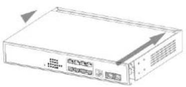
(4) Open the cover by holding two sides of the cover towards the direction of the arrow key shown in the following figure:
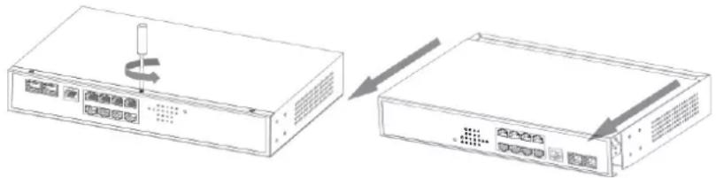
natural_image
Diagram showing two connected electronic devices with ports and a scroll arrow indicating rotation (no text or symbols)(5) When the cover is opened, put it aside. The main board of the system appears.
Note:
After taking off the cover, put it horizontally and avoid it to be crushed or collided. Otherwise, the chassis is hard to install.
4.2 Closing the Chassis
The section mainly describes how to put the cover and close the chassis. Do as follows:
(1) Following the directions shown on the above-mentioned figure, install the cover and bottom of the frame box.
natural_image
Line drawing of a server rack with ventilation slots and an arrow indicating direction (no text or symbols)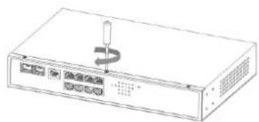
natural_image
Line drawing of a server rack with a screw and indicator lights (no text or symbols)(2) Nail the bolt and screw it tightly with the screwdriver.
(3) Reinstall the switch on the DIN rail or on the desk.
(4) Reconnect all cables of the switch.
Chapter 5 Hardware Fault Analysis
The part describes how to remove the faults from the switch.
5.1 Fault Separation
The key for resolving the systematic faults is to separate the fault from the system. You can compare what the system is doing with what the system should do to detect the fault. You need to check the following subsystems:
- Connection of the power supply and the cooling system — the power supply and the fan;
- Port, cable and connection—ports on the front template of the switch and the cables connecting these ports.
5.1.1 Faults Relative with Power and Cooling System
Do the following checkups to help remove the fault:
- When the power on-off is at the "ON" location, check whether the fan works normally.
- If the switch is too hot, check whether the air outlet and air inlet are clean and then do relative operations in section 2.3 "Requirements for Common Locations".
- If the switch cannot be started and the PWR indicator is off, check the power.
5.1.2 Faults Relative with Port, Cable and Connection
Do the following checkups to help remove the fault:
- If the port of the switch cannot be linked, check whether the cable is correctly connected and whether the peer connection is normal.
- If the console port does not work after the system is started up, check whether the console port is set to a baud rate of 9600 bps, eight data bits, no sum check bit, one stop bit and no traffic control.
5.2 LED Description
The LED shows that the switch is running. The following table shows the LEDs of the 8/24 switch and their description:
| No. | Abbrev. | Name | Remarks |
| 1 | PWR | Power LED | If the switch is powered, the indicator is on. |
| 2 | SYS | System LED | If the indicator is always on, the system is being started up.If the LED flickers, the system works normally. |
| 3 | LINK/ACT | port indicators | If the indicator is always on, it means that the connection is linked.If the indicator is off, the port is not linked. |
| 4 | PoE | PoE indicator corresponds to each port | If the indicator is always on, it means the PoE works.If the indicator is off, the PoE does not work. |
Copyright Claims
Without the written approval of the company, any person or group cannot transcribe, copy or change partial or all contents of this manual, and must not broadcast it in any manner.
Trademark claims
Trademarks, product names, service names and company names, which are written in this manual but do not belong to the company, belong to their owners respectively.
Disclaimer of warranty
provides no evident or hinted guarantee towards the contents of this manual. In no event, except for the company's breach of law, shall the company be liable for incidental, consequential, indirect or special damages of any kind or for loss of profits or revenue or loss of business arising out of or relating to this manual.
Note: Customer shall not be notified of this manual's content amendments.
Chapter 6 Specifications
| Item | 8 switch | 24 switch |
| Backplane | 20Gbps | 56Gbps |
| Forwarding rate | 15Mpps | 42Mpps |
| MAC | 8K | 8K |
| Ports | 8 10/100/1000Base-T ports, 21000Base-X ports | 24 10/100/1000Base-T ports, 41000Base-X ports |
| Dimensions(W× D× H)(mm) | 280*179*45 | 440×232×45 |
| Consumption | <15W | <15W |
| POE/POE+ | Support | Support |
| POE power consumption | POE 125W | POE 380W |
| Power supply | AC: 100V-240V, 50Hz±10% | |
| Environment | Operating temperature/humidity: 0°C-45°C, 5%-95% non-condensingStorage temperature/humidity: -20°C-70°C; 5%-95% non-condensing | |
| MAC exchange | Static configuration and dynamic MAC learning; MAC browsing and removalConfigurable aging time of the MAC address; Limited number of learnableMAC addresses; MAC filtration | |
| VLAN | 4K VLAN; GVRP; QinQ; Private VLAN | |
| STP | 802.1D (STP), 802.1W (RSTP) and 802.1S (MSTP)BPDU protection, root protection, and loopback protection | |
| Multicast | IGMP v1/v2/v3IGMP snoopingIGMP Fast LeaveMulticast group strategy and quantity limitationMulticast flow copying over VLANs | |
| QoS | Flow classification based on L2~4 protocolsCAR flow limit802.1P/DSCP priority re-labelingSP, WRR, and “SP+WRR”Congestion avoidance mechanisms like Tail-Drop and WREDFlow monitoring and flow shaping | |
| Security | L2/L3/L4 ACL flow identification and filtrationDDoS attack prevention, TCP's SYN Flood attack prevention, UDP Floodattack prevention, etcBroadcast/multicast/unknown unicast storm-controlPort isolationPort security, and “IP+MAC+port” binding | |
| Reliability | Static/LACP link aggregationEAPS and ERPS | |
| Management | Console, Telnet, SSH2.0, WebSNMP v1/v2/v3TFTPRMON | |

See Far, Go Further
- User Manual
- ALL RIGHTS RESERVED.
- About this Manual
- Trademarks Acknowledgement
- HIKVISION
- Legal Disclaimer
- Regulatory Information
- FCC Information
- FCC Conditions
- EU Conformity Statement
- Industry Canada ICES-003 Compliance
- Preparing for installation
- Symbol Conventions
- Table of Contents
- Chapter 1 8/24 Switch Overview
- Standard Configuration
- Characteristic Parameters of 8/24 switch
- Chapter 2 Installation Preparation
- Cautions
- Note:
- Safety Advice
- Safety Principles
- Safety Notices
- Safety Principles for Live Working
- Electrostatic Discharge Damage Prevention
- Requirements for Common Locations
- Environment
- Location Configuration Prevention
- Cabinet Configuration
- Power Requirements
- Caution:
- Installation Tools and Device
- Chapter 3 Installing the 8/24 Switch
- Installation Procedures of 8/24 switch
- Installing the Chassis of 8/24 switch
- Installing the Chassis on the Desk
- Installing the Chassis on the Cabinet
- Connecting the Port
- Connecting the Console Port
- Connecting the SFP Ports
- Connecting Gigabit Ethernet TX Ports
- Checkup after Installation
- Chapter 4 8/24 switch Maintenance
- Opening the Chassis
- Closing the Chassis
- Chapter 5 Hardware Fault Analysis
- Fault Separation
- Faults Relative with Power and Cooling System
- Faults Relative with Port, Cable and Connection
- LED Description
- Copyright Claims
- Trademark claims
- Disclaimer of warranty
Brand : Hikvision
Model : DS-3E2510P
Category : Network switch