
PG-QH13 - Heating Infiniton - Free user manual and instructions
Find the device manual for free PG-QH13 Infiniton in PDF.


| Product Type | Fan Heater |
| Model | PG-QH13 |
| Brand | Infiniton |
| Power (Max) | 2000 W |
| Power Settings | 2 (1000 W / 2000 W) |
| Voltage | 220–240 V ~ 50/60 Hz |
| Dimensions (H x W x D) | 250 mm x 200 mm x 150 mm |
| Weight | 1.5 kg |
| Heating Element | Ceramic |
| Thermostat | Adjustable |
| Safety Features | Overheat protection, tip-over switch |
| Oscillation | No |
| Controls | Mechanical dials |
| Color | White |
| Material | Plastic housing, metal grille |
| Noise Level | Approx. 50 dB |
| Room Coverage | Up to 20 m² |
| Cleaning | Wipe with dry cloth; unplug before cleaning |
| Repairability | Spare parts available via service center |
Frequently Asked Questions - PG-QH13 Infiniton
User questions about PG-QH13 Infiniton
0 question about this device. Answer the ones you know or ask your own.
Ask a new question about this device
Download the instructions for your Heating in PDF format for free! Find your manual PG-QH13 - Infiniton and take your electronic device back in hand. On this page are published all the documents necessary for the use of your device. PG-QH13 by Infiniton.
USER MANUAL PG-QH13 Infiniton
natural_image
Line drawing of a black electric stove with flame inside, placed in a minimalist living room with sofa and wall panels (no text or symbols)PG-QH13
ean: 8445639003114
natural_image
Simple line drawing of a lamp inside a transparent cube (no text or symbols)Nota Importante:
natural_image
Symbol of a trash bin crossed with a diagonal line, representing no waste or discharge (no text or numbers present)
Requisitos del gas
natural_image
Technical line drawing of a rectangular device with mounting brackets and a labeled component (B), no text or symbols present.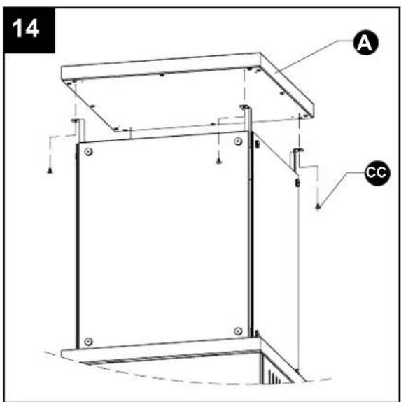
natural_image
Line drawing of a gas cylinder connected to a multi-tiered cylindrical device (no text or symbols visible)- Sólo para propano
natural_image
Technical line drawing of a multi-tiered industrial machine with open doors and internal components, shown with an inset magnified view (no text or symbols)Prueba de fugas
¡ADVERTENCIAS!
natural_image
Technical line drawing of a mechanical component with no visible text or symbolsnatural_image
Technical line drawing of a mechanical component with curved and straight sections (no text or symbols)natural_image
Technical line drawings of mechanical components, including a top view and a side-view cross-section (no text or symbols)



A
B
C
OFF
natural_image
Line drawing of a black electric stove with flame inside, placed on a sofa in an interior setting (no text or symbols)PG-QH13
ean: 8445639003114
| Safety information | 17 |
| Installation | 21 |
| Assembly | 22 |
| How to use | 29 |
| Cleaning & Maintenance | 31 |
PLEASE READ THE FOLLOWING SAFETY REGULATIONS BEFORE USING THE COOKER

WARNING!
If you smell gas:
- Shut off the gas inlets to the product.
- Extinguish any open flames.
- If odour continues, call your gas supplier or the fire service immediately.
WARNING!
- Do not store or use gasoline or other flammable vapors and liquids in the vicinity of this or any other product.
- Do not store a gas cylinder that is not connected for use in the vicinity of this or any other product.
WARNING!
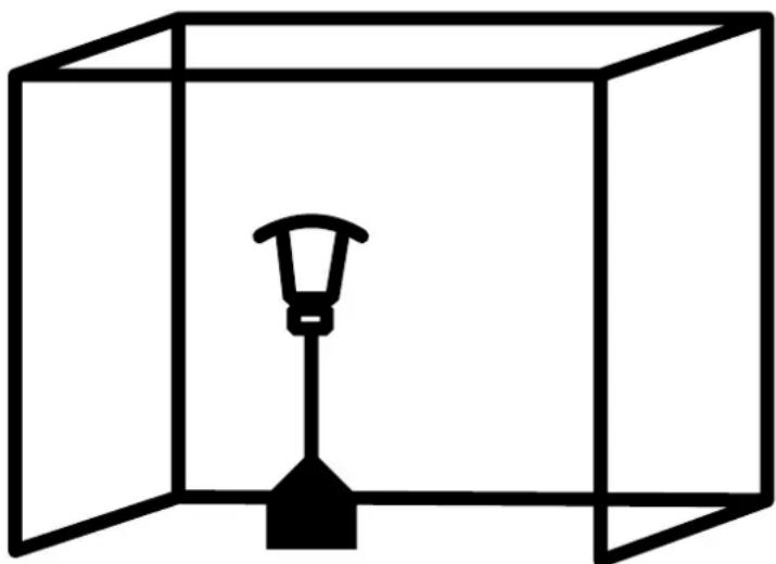
- Use outdoors or in well-ventilated areas.
- A well-ventilated area should have a minimum of 25% of the surface area open.
- The surface area is the sum of the surface area of the walls.
natural_image
Simple line drawing of a lamp inside a transparent cube (no text or symbols)Important note:
Improper installation, adjustment, alteration, service or maintenance can cause injury or property damage. Read the installation, operating and maintenance instructions carefully before installing or servicing this equipment.
This product must be installed and the gas cylinder must be stored in accordance with current regulations;
Do not obstruct the ventilation openings of the gas cylinder;
Do not move the product when in operation;
Close the valve on the gas cylinder or regulator before moving the product;
The tubing or flexible hose must be changed at the prescribed intervals;
Use only the type of gas and type of cylinder specified by the manufacturer;
The gas cylinder used with the outdoor kitchen must meet the following requirements:
Only purchase liquefied gas cylinders with these required dimensions:
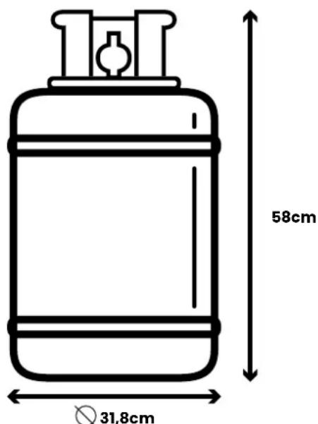
31.8cm diameter x 58cm high with a maximum capacity of 15kg.
In case of strong winds, special care must be taken to ensure that the product does not tilt; keep the product at least 1m away from the gas cylinder.
The injector is only installed by the manufacturer.
Do not connect the gas cylinder directly to the product without a regulator. Use only the type of gas and type of gas cylinder specified in the instructions.
Note:
You must have a regulator (complying with EN16129:2013 and national regulations) suitable for the pressure corresponding to the product category.
Use a 30 mbar regulator for butane/propane of category I3B/P(30). Use a 30 mbar regulator for butane of category I3+(28-30/37). Use a 37 mbar regulator for propane in category I3+(28-30/37). Use a 50 mbar regulator for butane/propane in category I3B/P(50). It is recommended to use flexible hoses approved according to ENI6436: 2014..
- Do not use the outdoor heater indoors as this may cause personal injury or damage to property.
- This outdoor heater is not designed for installation in leisure vehicles and/or boats.
• Installation and repair must be carried out by a qualified technician. - Improper installation, adjustment and modification may cause personal injury or property damage.
- Do not attempt to alter the unit in any way.
- Never replace or substitute the regulator with anything other than that suggested by the factory. Do not store or use gasoline or other flammable vapors or liquids in the heating unit.
- The entire gas system, hose, regulator, pilot or burner should be inspected for leaks or damage before the product is used and should be inspected at least once a year by a qualified technician.
-
All leak tests should be performed with a soap solution. Never use an open flame to test for leaks.
-
Do not use this appliance until all connections have been checked for leaks.
- Close the gas valve immediately if you smell gas. If the leak is at the hose/regulator connection, tighten the connection and perform another leak test.
- If the leak is at the hose/regulator connection, retighten the connection and perform another leak test. If bubbles continue to appear, return the hose to the shop of purchase. If the leak is at the regulator/valve connection on the cylinder: disconnect, reconnect and perform another leak test.
- Check for leaks. If bubbles still appear after several attempts, the cylinder valve is defective and must be returned to the place of purchase of the cylinder.
- Do not transport the appliance while it is in operation.
- Do not move the appliance after switching it off until the temperature has cooled down.
- Keep the ventilation opening of the appliance housing free and clear of debris.
- Do not paint the radiant screen, control panel or top cover reflector.
- The control compartment, burner and circulating air ducts of the cooker must be kept clean.
- Frequent cleaning may be necessary.
- The gas cylinder must be closed when this appliance is not in use.
Immediately check the condition of the cooker if any of the following occur situations:
- Burner does not reach temperature.
- Burner makes a lot of noise during use (a slight noise is normal when the burner is off).
- Gas odour accompanied by a strong yellow tinge to the burner flames.
- The gas regulator/hose assembly must be placed out of reach of persons who might trip over it or in an area where the hose cannot be accidentally damaged.
- Any guards or other protective devices that have been removed to service the cooker must be replaced before the stove is operated. Adults and children should be kept away from hot surfaces to avoid burns or burning of clothing.
- Children should be carefully supervised when in the cooker area.
- Clothing or other flammable materials should not be hung on the cooker or placed on or near the stove.
- Replace the gas cylinder in a well-ventilated area, away from any source of ignition such as candles, cigarettes, or other flame-producing products....
- Check that the regulator gasket is correctly positioned and can fulfil its function as shown in the following illustration:
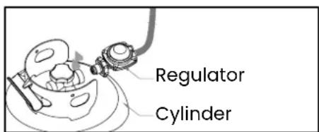
- Check the hose at least once a month, each time the canister is changed, or each time before a long period of inactivity.
- If it shows signs of cracking, splitting or other deterioration, it should be replaced with a new hose of the same length and equivalent quality;
- Use of this product in enclosed areas may be hazardous and is PROHIBITED;
Service & Disposal
- Any electrical work required to service the appliance must be carried out by a qualified electrician or competent person.
- This product must be serviced by an authorised Service Centre, and only original spare parts must be used.
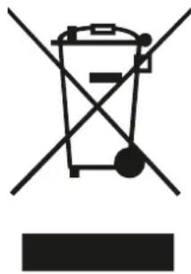
natural_image
Symbol of a trash bin crossed with a diagonal line and a horizontal bar below (no text or labels)This symbol on the product or on its packaging indicates that this product must not be treated as household waste. Instead, it must be taken to the appropriate collection point for the recycling of electrical and electronic equipment.
By ensuring this product is disposed of correctly, you will help prevent potential negative consequences for the environment and human health, which could otherwise be caused by inappropriate waste handling of this product.
For more detailed information about recycling of this product, please contact your local authorities, your household waste disposal service or the shop where you purchased the product.
Packing materials
Materials with the symbol 🎨 are recyclable. Dispose of the packaging in a suitable collection container for recycling.
Disposal of the device
- Disconnect the plug from the socket.
- Cut the power cord and discard it.
Heater position and levelling
- This heater is primarily intended for outdoor use. Always ensure that there is adequate ventilation of fresh air.
- Always keep an adequate distance to combustible elements, i.e. 100 cm at the top and at least 100 cm at the sides.
- The heater must be placed on a firm, level floor.
- Never use the heater in a potentially explosive atmosphere, which may contain petrol or other flammable liquids or vapours.
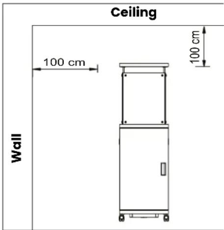
Gas requirements
- Use only propane, butane or any of their mixtures.
- The pressure regulator and hose assembly used must meet local code standards.
- Installation must conform to local codes or, in the absence of local codes, to the standard for storage and handling of liquefied petroleum gases.
- A dented, rusted or damaged cylinder can be dangerous and should be checked by your cylinder dealer.
- Never use a cylinder with a damaged valve.
- Never use a cylinder with a damaged valve connection.
- The cylinder must be prepared to allow the extraction of vapours from the cylinder.
- Never connect an unregulated cylinder.
Leak test
The gas connections of the heater are tested for tightness at the factory before shipment. A complete gas tightness check must be carried out at the installation site due to possible mishandling during transport or excessive pressure applied to the gas.
applied to it.
- Prepare a soap solution with one part liquid detergent and one part water. The soap solution can be applied with a spray bottle, brush or cloth. In case of leakage, soap bubbles will appear.
- Check the operation of the heater with a full drum.
- Make sure that the safety control valve is in the OFF position.
- Turn on the gas supply.
- In case of leakage, turn off the gas supply. Tighten any leaking connectors, turn on the gas supply and retest.
- Never leak test while smoking.
Tools needed
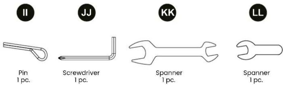
• Phillips screwdriver with medium blade
- Bottle with soap solution for leak test
Product parts
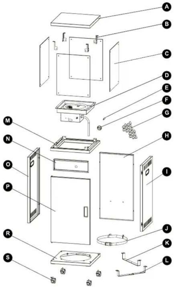
| Description Pcs | ||
| A Top cover 1 | ||
| B Top cover support 4 | ||
| C Glass panel 4 | ||
| D Burner | 1 | |
| E Valve 1 | ||
| F Control knob 1 | ||
| G Glass stones 1 | ||
| H Rear panel 1 | ||
| I Right side panel 1 | ||
| J Gas installation. Fixed support 1 | ||
| K Gas cylinder holder A 1 | ||
| L Gas cylinder holder B | 1 | |
| M Top cover 1 | ||
| N Control panel | 1 | |
| O Left side panel | 1 | |
| P Front door | 1 | |
| R Base | 1 | |
| S Wheels | 4 | |
Necessary elements
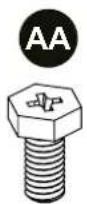
M6 X 12
Screw
21 pcs.
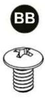
M5 X 8 Screw 4 pcs.
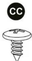
4.2 X 9.5
Screw
4 pcs.

M4 X 8 Screw 2 pcs.
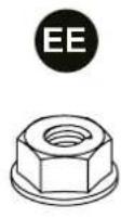
M4 X 8
Nut
1 pc.
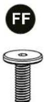
M6 X 16
Screw
16 pcs.
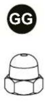
M6
Locking nut
16 pcs.
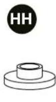
6mm
Arandela
32 uds.
Assembly procedure
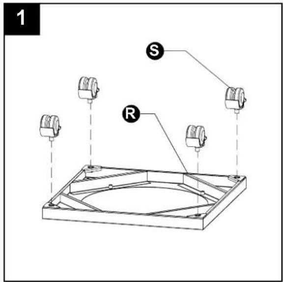
- Install the four wheels on the base.
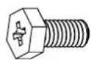
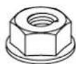
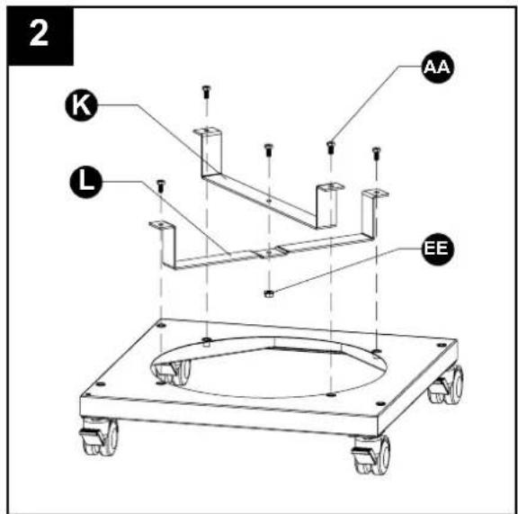
2.1. Install the gas cylinder brackets A and B to the base with four M6X12 hex screws.
2.2. Use one M6X12 hex bolt and one M6 hex flange nut between the two gas cylinder holders and then tighten the bolts.
Material needed

x 5

x 1
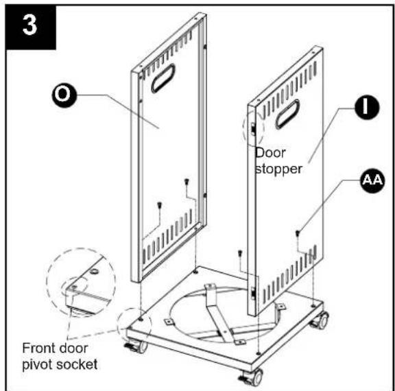
- Install the left and right side plates to the chassis with four M6X12 hex screws.
Note that the side plate that does not suction is the left side, which is installed on the side with the front door hole, and the right side plate that does suction is installed on the other side).
Material needed

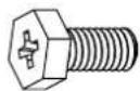
x 4
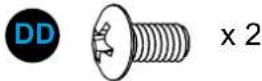
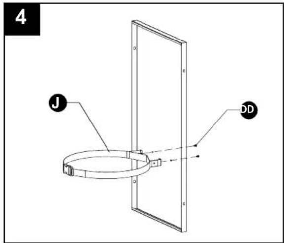
- Install the gas cylinder holder on the inner side of the back plate with two M4 X8 screws.
Material needed
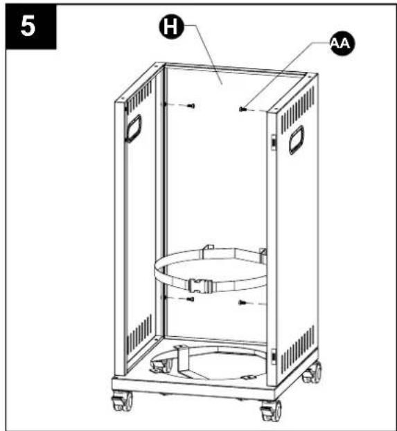
- Install the rear cover on the left and right side walls with four M6X12 hexagonal screws (note that the gas cylinder holder must be located at the bottom.
Material needed
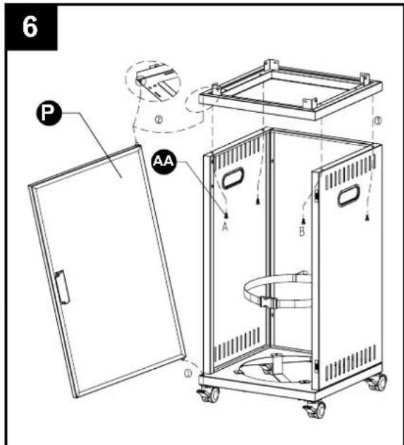
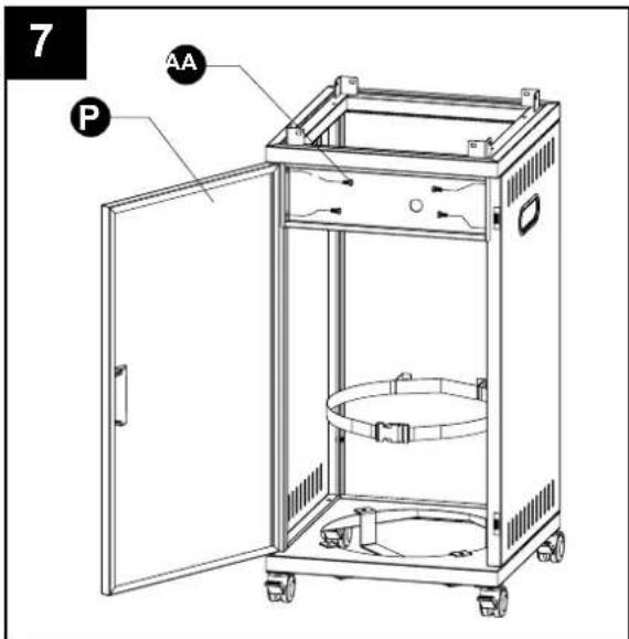
6.1. Insert the pivot shaft in the lower left-hand corner of the front door into the hole in the chassis pivot shaft.
6.2. Straighten the front door, then place the top of the box plate over the left and right side plates of the box, and insert the pivot shaft at the top left of the front door into the pivot shaft hole at the bottom left of the top plate of the box.
6.3. Adjust the position of the enclosure body top plate and the left and right side plates so that the mounting screw holes on the bottom of the enclosure body top plate are aligned with the mounting holes on the left and right side plates, and tighten the enclosure body top plate from the inside with four M6X12 hex screws.
Material needed
- Install the control panel hole on the right side in the middle of the top of the left and right side plates, fix it with four M6X12 hex screws, close the front door, adjust the clearance between the front door and the top plate of the enclosure, then open the front door and tighten the screws. Adjust the installation so that the front door can have an even gap with the top plate and enclosure chassis. If the control panel cannot be placed smoothly between the left and right side plates, loosen screws A and B in the previous step, and then tighten screws A and B after assembling this step.
Material needed

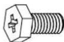
x 4
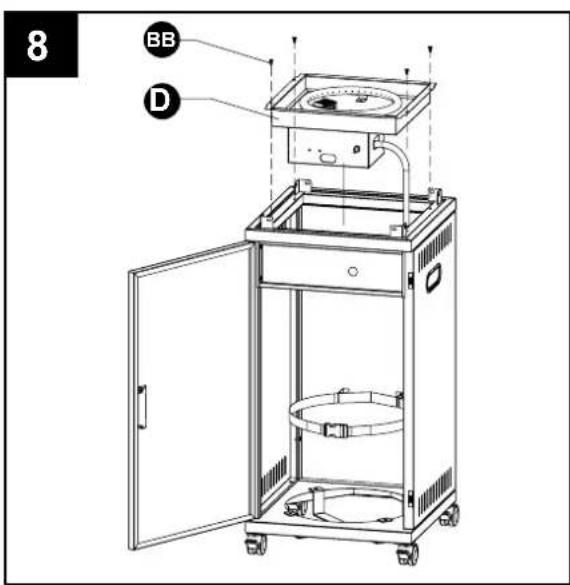
- Position the burner head valve in front of the top of the housing body, and screw the burner head to the top plate of the housing body with four M5X8 screws.
Material needed

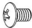
x 4
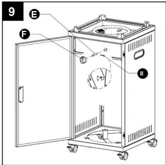
- Insert the valve extension rod into the valve stem through the round hole in the control panel, then insert the nut on the inside of the extension rod and push it in. Then insert a union pin into the anti-drop hole of the extension rod that communicates with the valve from the inside and bend the union pin.
Material needed

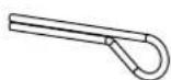
x 1
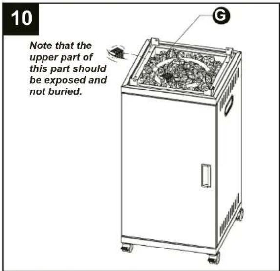
- Pour in the glass stones, and the top of the ignition protection cover should be exposed.
Note that the top of the burner must be exposed and not buried.
-
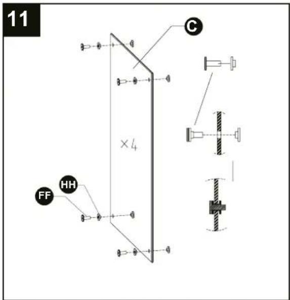
As shown in the figure
-
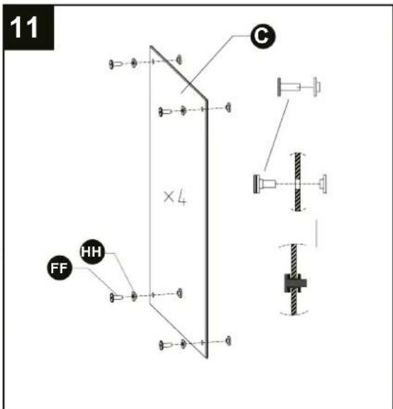
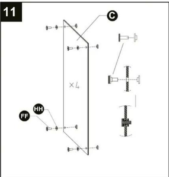
First, insert the convex surface of the T-shaped silicone heater plate into the M6X16 hexagon socket head cap screw and push the gasket all the way to the end of the screw.
- Next, insert the screws inserted into the silicone gasket in step 1 into the holes in the four corners of the glass in the same direction in succession.
- Place the convex surface of the silicone gasket on the screw from the back towards the glass, and press the screw so that it is in close contact with the silicone gasket on the back.
Material needed

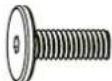
x 16

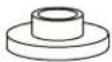
x 32
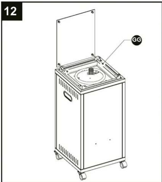
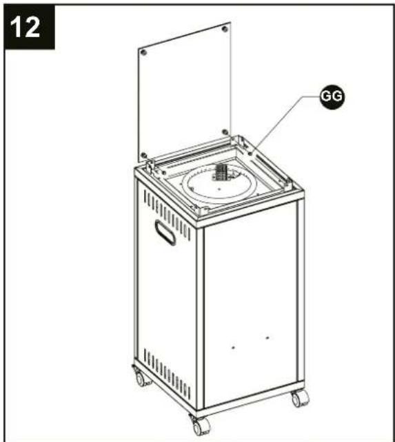
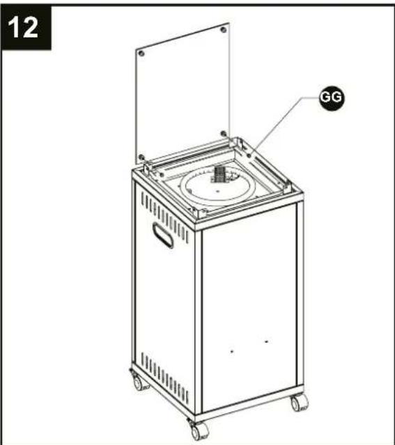
12-1. Insert the screw previously placed in step 11 and two screws at one end of the silicon gasket tempered glass into the bracket holes at both ends of the top of the enclosure, screw in with M6 blind nuts from the inside and adjust the position of the tempered glass to the centre.
12-2. Assemble the remaining pieces of tempered glass to it in turn by following the steps shown.
12-3. Adjust the spacing at the bottom of each glass to be uniform, then screw the screws until the silicone gaskets on both sides of the glass are fully tightened to the glass, and then continue tightening the nuts for half a turn.
Material needed


×8
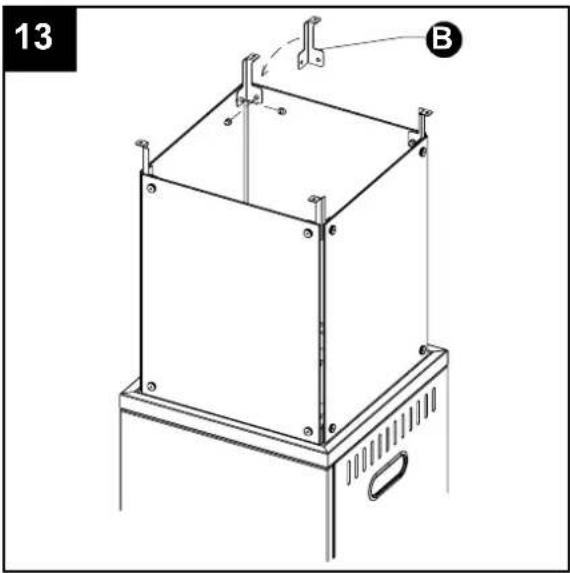
13-1. Insert the two mounting holes on the bottom of the top cover bracket into the screws on the top corner of the tempered glass cover, and then tighten the screws following the method in step 11.
13-2. Install the remaining 3 cover brackets in succession.
Material needed


×8
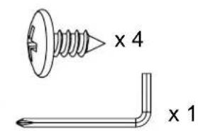
- Place the top cover over the four top cover brackets and adjust the screw holes on the left side of the four corners of the top cover to align with the mounting holes of the top cover brackets. Secure the top cover and bracket with four 4.8x9.5 tapping screws.
Material needed

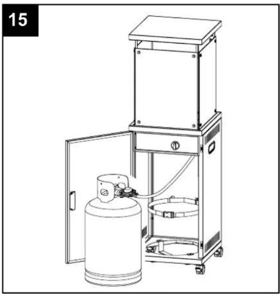
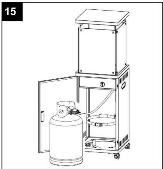
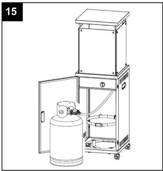
- Connect the hose and regulator to the cylinder. Propane gas and cylinder are sold separately.
natural_image
Technical line drawing of a rectangular industrial machine with mounting brackets and a labeled component (B), no text or symbols present.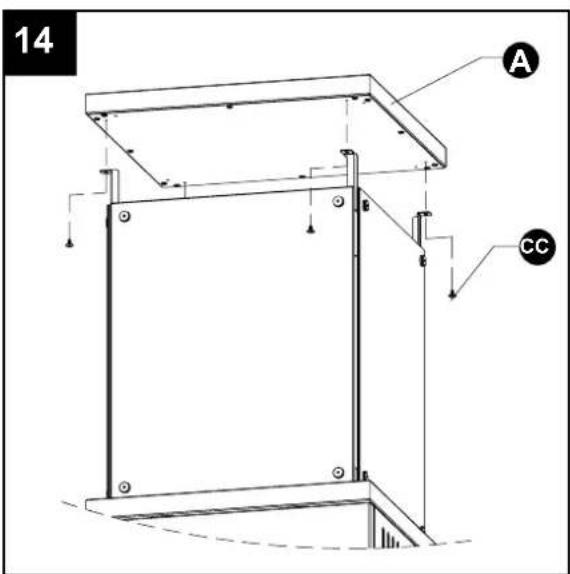
natural_image
Line drawing of a gas cylinder inside a multi-tiered cylindrical device (no text or symbols)- For propane only
Correct hose connection.
WARNING!
Make sure that the hose does not come into contact with any high temperature surface, or it may melt and leak causing a fire.
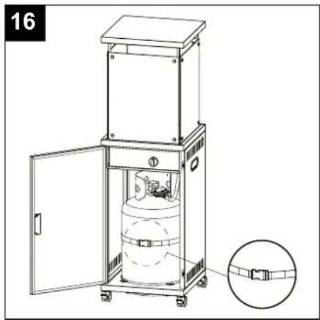
Once the canister is placed inside the heater, secure it firmly with the locking strap.
natural_image
Technical line drawing of a mechanical device with open door and internal cylindrical housing, showing internal components and a close-up inset (no text or symbols)Leak test
WARNINGS!
A leak test must be carried out annually and every time a cylinder is connected or if part of the gas system is replaced.
cylinder is connected or if a part of the gas system is replaced.
Never use an open flame to check for gas leaks. Make sure there are no sparks or open flames in the area while checking for leaks.
Sparks or open flames can cause a fire or explosion, property damage, serious bodily injury or death.
Tightness Test: Must be performed before first use, annually, and whenever any part using any gas is replaced.
Components are replaced or repaired.
Do not smoke while performing this test and eliminate all sources of ignition. Refer to the leak test diagram for areas to be checked. Turn all burner controls to the off position. Open the gas supply valve.
Brush a solution of liquid soap and water halfway into all joints and connections of the regulator, hose, manifolds and valves.
Bubbles will indicate a gas leak. Tighten the loose gasket or replace the part with one recommended by the service technician and have the patio heater inspected by a certified gas fitter.
If the leak cannot be stopped, immediately turn off the gas supply,
disconnect and have the patio heater inspected by a certified gas fitter or dealer.
certified gas fitter or dealer. Do not use the patio heater until the leak has been corrected.
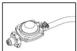
natural_image
Technical line drawing of a mechanical component with no visible text or symbolsRegulator / hose connection
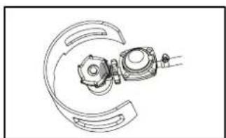
natural_image
Technical line drawing of a mechanical component with curved and flanged parts (no text or symbols)Connection of the regulator to the gas cylinder
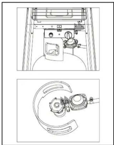
natural_image
Technical line drawings of mechanical components, showing top and side views (no text or symbols)



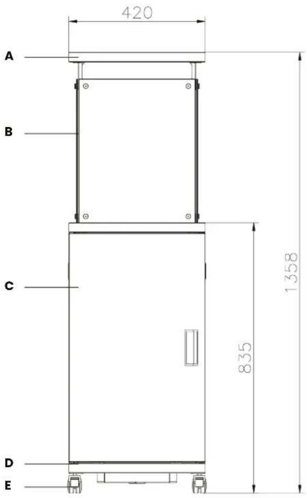
Description of the parts
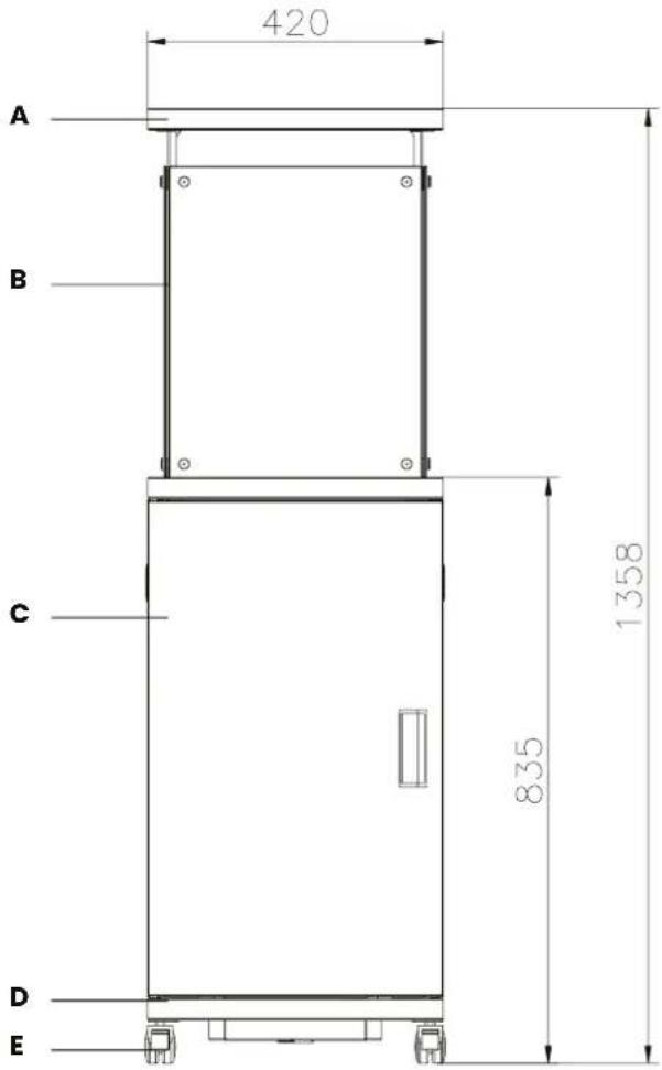
| A Top cover |
| B Glass panel |
| C Front door |
| D Base |
| E Wheels |
Materials and characteristics
• Outdoor gas heater with storage tank
• Steel casing with metallic paint or stainless steel coating
- Gas hose connections with metal clamp (screw plugs for Germany)
Specifications
• Gas heater suitable for propane, butane and mixed gas.
• Maximum power: 13.000W
Consumption:
| Product category 13+ (28-30/37) | 13B/P(30) 13B/P (50) 13B/P(37) | ||||
| Gas type Butane | Propane | But,prop,mix But | prop,mix But,prop,mix | ||
| Gas pressure 28-30 mbar | 37mbar 30mbar 50mbar | 37mbar | |||
| Regulator outlet pres-sure | 30mbar 37mbar 30mbar 50mbar 37mbar | ||||
Injector table:
| Product category 13+ (28-30/37) | 13B/P(30) 13B/P(50) 13B/P(37) | ||||
| Gas type Butane | Propane But,prop,mix | But,prop,mix But,prop,mix | |||
| Gas pressure 28-30 mbar | 37mbar 30mbar | 50mbar 37mbar | |||
| TOTAL HEAT INPUT (Hs): (Qn) | 13kW (G30:946g/h; G31:929g/h) | ||||
| INJECTOR SIZE | 1.90mm main burner | 1.70mm main burner | 1.80mm main burner | ||
- The hose and regulator assembly must meet local code standards.
• The regulator outlet pressure must comply with the appropriate product category in Specification B.
• The product requires a 0.6 m length of approved hose.
Switching on the heater
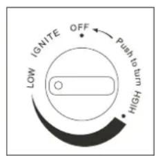
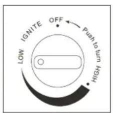
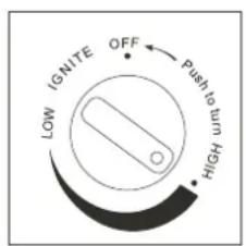
- Turn the control knob to the "OFF" position (Figure a).
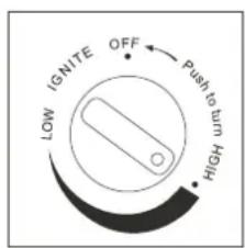
- Open the gas cylinder valve fully. Note: For initial start-up or after any cylinder change, hold the control knob in for 10 seconds to purge air from the gas lines before proceeding. Push in the gas control knob and turn it counterclockwise to "IGNITER" (Figure b) to light the fire.
- If necessary, continue to press and turn the control knob counterclockwise until the heater ignites (a clicking sound should be heard).
- Once the fire is lit, release the control knob. Press and turn the control knob to the "HIGH" position, then release the control knob. If a lower temperature is desired, press the control knob and turn it clockwise to the "LOW" position (Figure c).
Notes:
If the burner does not stay lit, all valves must be closed and a waiting period of at least 5 minutes must elapse before attempting to light the burner.
Switching off the heater
- To turn the burner off, press the control knob and turn it clockwise to the OFF position.
- Turn the cylinder valve clockwise to the OFF position and disconnect the regulator when the burner is not in use.
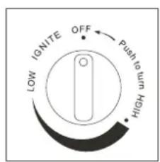
A
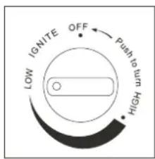
B
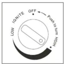
C
OFF
Heater stops working
HI
Maximum temperature position
LO
Minimum temperature position
If this heater model has glass panes, check that there are no cracks in the panes before lighting the heater.
Storage
- Always close the gas valve on the cylinder after use or if there are any problems.
- Remove the pressure regulator and hose.
- Check the gas valve for looseness or damage; if you think it is damaged, ask your gas supplier to replace it.
- Never store the gas cylinder in places without adequate ventilation.
Troubleshooting
Whenever there is a problem with the appliance, check if you can solve it by following the tables below. If the problem persists, contact customer service.
| DESCRIPTION POSSIBLE CAUSE SOLUTION | ||
| Burner does not light Low pres | sureOpening blockedControl not connectedThermocouple defectivePilot assembly damagedIncorrect location. | Tank almost empty. Refill LPG tank.Remove and cleanTurn valve to ON positionReplace thermocoupleFit pilot correctlyFit correctly and try again |
Cleaning and maintenance
- Clean dusty surfaces with a soft, damp cloth. Do not clean the heater with combustible or corrosive cleaning agents.
- Remove debris from the burner to keep it clean and safe for use.
- Cover the burner unit with the optional protective cover when the heater is not in use.
INFINITON
FOGÃO A GÁS
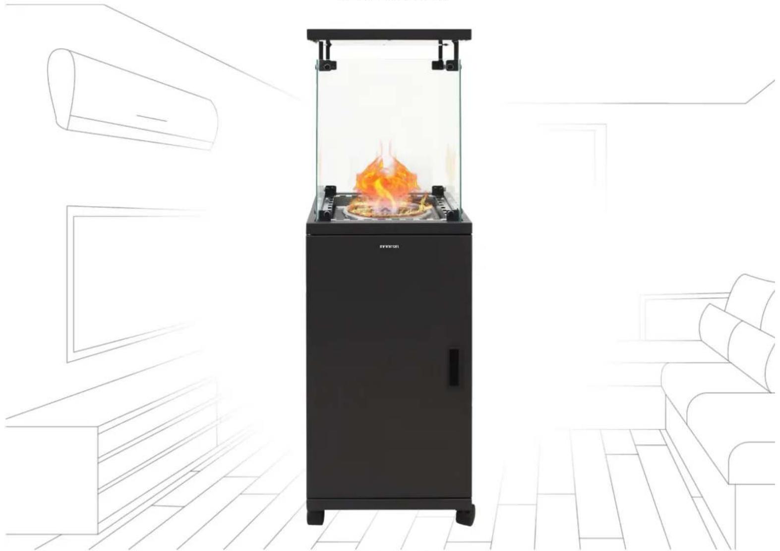
natural_image
Line drawing of a black portable gas stove with visible flame inside, placed on a patterned floor next to a sofa and wall (no text or symbols)PG-QH13
ean: 8445639003114
natural_image
Simple line drawing of a lamp inside a transparent cube (no text or symbols)Nota importante:
natural_image
Symbol of a trash bin crossed with a diagonal line and a horizontal bar below (no text or labels)Material necessário

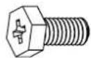
x 4
Material necessário

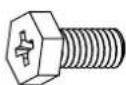
x 4
natural_image
Technical line drawing of a rectangular enclosure with mounting feet and a side panel, labeled with number 13 (no text or symbols on the diagram itself)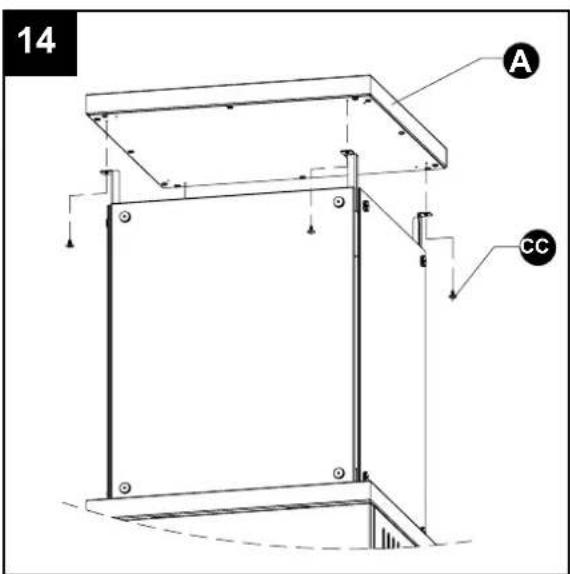
natural_image
Line drawing of a laboratory gas cylinder connected to a multi-tiered cylindrical device (no text or symbols)- Apenas para propano
natural_image
Technical line drawing of a multi-tiered industrial machine with open doors and internal components, shown with an inset magnified view (no text or symbols)Teste de fugas
AVISOS!
natural_image
Technical line drawing of a mechanical component with no visible text or symbolsnatural_image
Technical line drawing of a mechanical assembly with no visible text or symbolsnatural_image
Technical line drawings of mechanical components, showing top and side views (no text or symbols)



Descrição das peças
| A Tampa superior | |
| B Painel de vidro | |
| C Porta frontal | |
| D Base | |
| E Rodas |
A
B
C
OFF
¿Necesitas ayuda?
natural_image
Silhouette icon of a person wearing a headset with a crossed wrench symbol (no text or numbers)
INFINITON
TÉRMINOS Y REGISTRO DE GARANTÍA
- Nota Importante:
- Requisitos del gas
- Prueba de fugas
- ¡ADVERTENCIAS!
- OFF
- PLEASE READ THE FOLLOWING SAFETY REGULATIONS BEFORE USING THE COOKER
- WARNING!
- If you smell gas:
- Important note:
- 31.8cm diameter x 58cm high with a maximum capacity of 15kg.
- Note:
- Immediately check the condition of the cooker if any of the following occur situations:
- Service & Disposal
- Packing materials
- Disposal of the device
- Heater position and levelling
- Gas requirements
- Leak test
- Tools needed
- Assembly procedure
- Material needed
- WARNINGS!
- Description of the parts
- Materials and characteristics
- Specifications
- Consumption:
- Injector table:
- Switching on the heater
- Notes:
- Switching off the heater
- HI
- LO
- Storage
- Troubleshooting
- Cleaning and maintenance
- INFINITON
- Material necessário
- Teste de fugas
- AVISOS!
- Descrição das peças
- ¿Necesitas ayuda?
- TÉRMINOS Y REGISTRO DE GARANTÍA
Brand : Infiniton
Model : PG-QH13
Category : Heating