
G10BYEQ2 - Angle Grinder HiKOKI - Free user manual and instructions
Find the device manual for free G10BYEQ2 HiKOKI in PDF.


| Product Type | Disc Grinder (Angle Grinder) |
| Brand | HiKOKI |
| Model | G10BYEQ2 |
| Voltage | 220 V – 240 V~ (depending on area) |
| Power Input | 1200 W (220 V) / 1320 W (230–240 V) |
| Rated Speed | 10,000 /min |
| Wheel Outer Diameter | 100 mm |
| Wheel Thickness | 6 mm |
| Wheel Hole Diameter | 16 mm |
| Weight (main body only) | 1.6 kg |
| Soft Start | Reduces recoil by managing startup rotations |
| Constant Speed Control | Maintains speed under load |
| Overload Protection | Cuts power to motor when overloaded; resets after removing cause |
| Overheat Protection | Cuts power to motor if overheating occurs; cools down to reset |
| Brake Function | Electric brake activates when switch is released; works even during power outage |
| 0 Voltage Restart Protection | Prevents tool from restarting after power interruption; switch must be turned off then on |
| Rotation Recovery Control | Motor automatically resumes after overload if cause is eliminated |
| Standard Accessories | Wrench (1), Side handle (1), Depressed center wheel (1) |
| Safety Guard | Wheel guard with adjustable position; cutting guard required for cut-off wheels |
| Filter Set | Mesh filter to reduce dust ingress; clean and inspect regularly |
| Applications | Grinding, cutting (with appropriate wheel), deburring, surface finishing on metal, stone, concrete, etc. |
| Maintenance | Regularly clean air vents and filter; inspect wheel for damage; service only by HiKOKI authorized center |
Frequently Asked Questions - G10BYEQ2 HiKOKI
User questions about G10BYEQ2 HiKOKI
0 question about this device. Answer the ones you know or ask your own.
Ask a new question about this device
Download the instructions for your Angle Grinder in PDF format for free! Find your manual G10BYEQ2 - HiKOKI and take your electronic device back in hand. On this page are published all the documents necessary for the use of your device. G10BYEQ2 by HiKOKI.
USER MANUAL G10BYEQ2 HiKOKI
natural_image
Line drawing of a power tool with angular grip and base, enclosed in a circular frame (no text or symbols)
2


3


4



5


6


8
9

GENERAL POWER TOOL SAFETY WARNINGS

WARNING
Read all safety warnings and all instructions.
Failure to follow the warnings and instructions may result in electric shock, fi re and/or serious injury.
Save all warnings and instructions for future reference.
The term “power tool” in the warnings refers to your mains-operated (corded) power tool or battery-operated (cordless) power tool.
1) Work area safety
a) Keep work area clean and well lit. Cluttered or dark areas invite accidents
b) Do not operate power tools in explosive atmospheres, such as in the presence of fl ammable liquids, gases or dust. Power tools create sparks which may ignite the dust or fumes.
c) Keep children and bystanders away while operating a power tool. Distractions can cause you to lose control.
2) Electrical safety
a) Power tool plugs must match the outlet. Never modify the plug in any way. Do not use any adapter plugs with earthed (grounded) power tools. Unmodified plugs and matching outlets will reduce risk of electric shock.
b) Avoid body contact with earthed or grounded surfaces, such as pipes, radiators, ranges and refrigerators. There is an increased risk of electric shock if your body is earthed or grounded.
c) Do not expose power tools to rain or wet conditions. Water entering a power tool will increase the risk of electric shock.
d) Do not abuse the cord. Never use the cord for carrying, pulling or unplugging the power tool. Keep cord away from heat, oil, sharp edges or moving parts. Damaged or entangled cords increase the risk of electric shock.
e) When operating a power tool outdoors, use an extension cord suitable for outdoor use. Use of a cord suitable for outdoor use reduces the risk of electric shock.
f) If operating a power tool in a damp location is unavoidable, use a residual current device (RCD) protected supply. Use of an RCD reduces the risk of electric shock.
3) Personal safety
a) Stay alert, watch what you are doing and use common sense when operating a power tool. Do not use a power tool while you are tired or under the influence of drugs, alcohol or medication. A moment of inattention while operating power tools may result in serious personal injury.
b) Use personal protective equipment. Always wear eye protection. Protective equipment such as dust mask, non-skid safety shoes, hard hat, or hearing protection used for appropriate conditions will reduce personal injuries.
c) Prevent unintentional starting. Ensure the switch is in the off position before connecting to power source and/or battery pack, picking up or carrying the tool.
Carrying power tools with your fi nger on the switch or energising power tools that have the switch on invites accidents.
d) Remove any adjusting key or wrench before turning the power tool on.
A wrench or a key left attached to a rotating part of the power tool may result in personal injury.
e) Do not overreach. Keep proper footing and balance at all times. This enables better control of the power tool in unexpected situations.
f) Dress properly. Do not wear loose clothing or jewellery. Keep your hair, clothing and gloves away from moving parts.
Loose clothes, jewellery or long hair can be caught in moving parts.
g) If devices are provided for the connection of dust extraction and collection facilities, ensure these are connected and properly used. Use of dust collection can reduce dust-related hazards.
4) Power tool use and care
a) Do not force the power tool. Use the correct power tool for your application. The correct power tool will do the job better and safer at the rate for which it was designed.
b) Do not use the power tool if the switch does not turn it on and off. Any power tool that cannot be controlled with the switch is dangerous and must be repaired.
c) Disconnect the plug from the power source and/or the battery pack from the power tool before making any adjustments, changing accessories, or storing power tools. Such preventive safety measures reduce the risk of starting the power tool accidentally.
d) Store idle power tools out of the reach of children and do not allow persons unfamiliar with the power tool or these instructions to operate the power tool.
Power tools are dangerous in the hands of untrained users.
e) Maintain power tools. Check for misalignment or binding of moving parts, breakage of parts and any other condition that may affect the power tool's operation.
If damaged, have the power tool repaired before use. Many accidents are caused by poorly maintained power tools.
f) Keep cutting tools sharp and clean. Properly maintained cutting tools with sharp cutting edges are less likely to bind and are easier to control.
g) Use the power tool, accessories and tool bits etc. in accordance with these instructions, taking into account the working conditions and the work to be performed. Use of the power tool for operations different from those intended could result in a hazardous situation.
5) Service
a) Have your power tool serviced by a qualified repair person using only identical replacement parts. This will ensure that the safety of the power tool is maintained.
PRECAUTION
Keep children and infi rm persons away.
When not in use, tools should be stored out of reach of children and infi rm persons.
SAFETY WARNINGS COMMON FOR GRINDING OR ABRASIVE CUTTING-OFF OPERATIONS
a) This power tool is intended to function as a grinder or cut-off tool. Read all safety warnings, instructions, illustrations and specifications provided with this power tool.
Failure to follow all instructions listed below may result in electric shock, fire and/or serious injury.
b) Operations such as sanding, wire brushing or polishing are not recommended to be performed with this power tool.
Operations for which the power tool was not designed may create a hazard and cause personal injury.
c) Do not use accessories which are not specifically designed and recommended by the tool manufacturer.
Just because the accessory can be attached to your power tool, it does not assure safe operation.
d) The rated speed of the accessory must be at least equal to the maximum speed marked on the power tool.
Accessories running faster than their rated speed can break and fly apart.
e) The outside diameter and the thickness of your accessory must be within the capacity rating of your power tool.
Incorrectly sized accessories cannot be adequately guarded or controlled.
f) Threaded mounting of accessories must match the grinder spindle thread. For accessories mounted by fl anges, the arbour hole of the accessory must fit the locating diameter of the fl ange.
Accessories that do not match the mounting hardware of the power tool will run out of balance, vibrate excessively and may cause loss of control.
g) Do not use a damaged accessory. Before each use inspect the accessory such as abrasive wheels for chips and cracks, backing pad for cracks, tear or excess wear, wire brush for loose or cracked wires. If power tool or accessory is dropped, inspect for damage or install an undamaged accessory. After inspecting and installing an accessory, position yourself and bystanders away from the plane of the rotating accessory and run the power tool at maximum no-load speed for one minute.
Damaged accessories will normally break apart during this test time.
h) Wear personal protective equipment. Depending on application, use face shield, safety goggles or safety glasses. As appropriate, wear dust mask, hearing protectors, gloves and workshop apron capable of stopping small abrasive or workpiece fragments.
The eye protection must be capable of stopping flying debris generated by various operations. The dust mask or respirator must be capable of filtrating particles generated by your operation. Prolonged exposure to high intensity noise may cause hearing loss.
i) Keep bystanders a safe distance away from work area. Anyone entering the work area must wear personal protective equipment.
Fragments of workpiece or of a broken accessory may fly away and cause injury beyond immediate area of operation.
j) Hold the power tool by insulated gripping surfaces only, when performing an operation where the cutting accessory may contact hidden wiring or its own cord.
Cutting accessory contacting a "live" wire may make exposed metal parts of the power tool "live" and could give the operator an electric shock.
k) Position the cord clear of the spinning accessory. If you lose control, the cord may be cut or snagged and your hand or arm may be pulled into the spinning accessory.
I) Never lay the power tool down until the accessory has come to a complete stop.
The spinning accessory may grab the surface and pull the power tool out of your control.
m) Do not run the power tool while carrying it at your side. Accidental contact with the spinning accessory could snag your clothing, pulling the accessory into your body.
n) Regularly clean the power tool's air vents.
The motor's fan will draw the dust inside the housing and excessive accumulation of powdered metal may cause electrical hazards.
o) Do not operate the power tool near fl ammable materials. Sparks could ignite these materials.
p) Do not use accessories that require liquid coolants. Using water or other liquid coolants may result in electrocution or shock.
KICKBACK AND RELATED WARNINGS
Kickback is a sudden reaction to a pinched or snagged rotating wheel, backing pad, brush or any other accessory. Pinching or snagging causes rapid stalling of the rotating accessory which in turn causes the uncontrolled power tool to be forced in the direction opposite of the accessory's rotation at the point of the binding.
For example, if an abrasive wheel is snagged or pinched by the workpiece, the edge of the wheel that is entering into the pinch point can dig into the surface of the material causing the wheel to climb out or kick out. The wheel may either jump toward or away from the operator, depending on direction of the wheel's movement at the point of pinching.
Abrasive wheels may also break under these conditions.
Kickback is the result of power tool misuse and/or incorrect operating procedures or conditions and can be avoided by taking proper precautions as given below.
a) Maintain a fi rm grip on the power tool and position your body and arm to allow you to resist kickback forces. Always use auxiliary handle, if provided, for maximum control over kickback or torque reaction during start-up. The operator can control torque reactions or kickback forces, if proper precautions are taken.
b) Never place your hand near the rotating accessory. Accessory may kickback over your hand.
c) Do not position your body in the area where power tool will move if kickback occurs.
Kickback will propel the tool in direction opposite to the wheel's movement at the point of snagging.
d) Use special care when working corners, sharp edges etc. Avoid bouncing and snagging the accessory.
Corners, sharp edges or bouncing have a tendency to snag the rotating accessory and cause loss of control or kickback.
e) Do not attach a saw chain woodcarving blade or toothed saw blade.
Such blades create frequent kickback and loss of control.
SAFETY WARNINGS SPECIFIC FOR GRINDING AND ABRASIVE CUTTING-OFF OPERATIONS
a) Use only wheel types that are recommended for your power tool and the specific guard designed for the selected wheel.
Wheels for which the power tool was not designed cannot be adequately guarded and are unsafe.
b) The grinding surface of centre depressed wheels must be mounted below the plane of the guard lip. An improperly mounted wheel that projects through the plane of the guard lip cannot be adequately protected.
c) The guard must be securely attached to the power tool and positioned for maximum safety, so the least amount of wheel is exposed towards the operator.
The guard helps to protect the operator from broken wheel fragments, accidental contact with wheel and sparks that could ignite clothing.
d) Wheels must be used only for recommended applications. For example: do not grind with the side of cut-off wheel.
Abrasive cut-off wheels are intended for peripheral grinding, side forces applied to these wheels may cause them to shatter.
e) Always use undamaged wheel fl anges that are of correct size and shape for your selected wheel.
Proper wheel flanges support the wheel thus reducing the possibility of wheel breakage. Flanges for cut-off wheels may be different from grinding wheel flanges.
f) Do not use worn down wheels from larger power tools.
Wheel intended for larger power tool is not suitable for the higher speed of a smaller tool and may burst.
ADDITIONAL SAFETY WARNINGS SPECIFIC FOR ABRASIVE CUTTING- OFF OPERATIONS
a) Do not "jam" the cut-off wheel or apply excessive pressure. Do not attempt to make an excessive depth of cut.
Overstressing the wheel increases the loading and susceptibility to twisting or binding of the wheel in the cut and the possibility of kickback or wheel breakage.
b) Do not position your body in line with and behind the rotating wheel.
When the wheel, at the point of operation, is moving away from your body, the possible kickback may propel the spinning wheel and the power tool directly at you.
c) When wheel is binding or when interrupting a cut for any reason, switch off the power tool and hold the power tool motionless until the wheel comes to a complete stop. Never attempt to remove the cut-off wheel from the cut while the wheel is in motion otherwise kickback may occur.
Investigate and take corrective action to eliminate the cause of wheel binding.
d) Do not restart the cutting operation in the workpiece. Let the wheel reach full speed and carefully re-enter the cut.
The wheel may bind, walk up or kickback if the power tool is restarted in the workpiece.
e) Support panels or any oversized workpiece to minimize the risk of wheel pinching and kickback.
Large workpieces tend to sag under their own weight. Supports must be placed under the workpiece near the line of cut and near the edge of the workpiece on both sides of the wheel.
f) Use extra caution when making a "pocket cut" into existing walls or other blind areas.
The protruding wheel may cut gas or water pipes, electrical wiring or objects that can cause kickback.
GENERAL SAFETY INSTRUCTIONS FOR GRINDERS
- Check that speed marked on the wheel is equal to or greater than the rated speed of the grinder;
- Ensure that the wheel dimensions are compatible with the grinder;
- Abrasive wheels shall be stored and handled with care in accordance with manufacturer's instructions;
- Inspect the grinding wheel before use, do not use chipped, cracked or otherwise defective products;
- Ensure that mounted wheels and points are fitted in accordance with the manufacturer's instructions;
- Ensure that blotters are used when they are provided with the bonded abrasive product and when they are required;
- Ensure that the abrasive product is correctly mounted, and tightened before use and run the tool at no-load for 30 seconds in a safe position, stop immediately if there is considerable vibration or if other defects are detected. If this condition occurs, check the machine to determine the cause;
- If a guard is equipped with the tool never use the tool without such a guard;
- When using an abrasive cutting wheel, be sure to remove the standard accessory wheel guard and attach the wheel guard with side guard (sold separately) (Fig. 5);
- Do not use separate reducing bushings or adapters to adapt large hole abrasive wheels;
- For tools intended to be fitted with threaded hole wheel, ensure that the thread in the wheel is long enough to accept the spindle length;
– Check that the work piece is properly supported; - Do not use cutting off wheel for side grinding;
- Ensure that sparks resulting from use do not create a hazard e.g. do not hit persons, or ignite flammable substances;
- Ensure that ventilation openings are kept clear when working in dusty conditions, if it should become necessary to clear dust, fi rst disconnect the tool from the mains supply (use non metallic objects) and avoid damaging internal parts;
- Always use eye and ear protection. Other personal protective equipment such as dust mask, gloves, helmet and apron should be worn;
- Pay attention to the wheel that continues to rotate after the tool is switched off.
WARNING
- When using a cutting-off wheel, be sure to attach the cutting-off guard.
- When using a grinding wheel, be sure to attach the grinding wheel guard.
ADDITIONAL SAFETY WARNINGS
- Ensure that the power source to be utilized conforms to the power requirements specified on the product nameplate.
- Ensure that the power switch is in the OFF position. If the plug is connected to a receptacle while the power switch is in the ON position, the power tool will start operating immediately, which could cause a serious accident.
- When the work area is removed from the power source, use an extension cord of sufficient thickness and rated capacity. The extension cord should be kept as short as practicable.
- Ensure that the depressed center wheel to be utilized is the correct type and free of cracks or surface defects. Also ensure that the depressed center wheel is properly mounted and the wheel nut is securely tightened.
English
- Confi rm that the push button is disengaged by pushing push button two or three times before switching the power tool on.
- To prolong the life of the machine and ensure a first class fi nish, it is important that the machine should not be overloaded by applying too much pressure. In most applications, the weight of the machine alone is suffi cient for eff ective grinding. Too much pressure will result in reduced rotational speed, inferior surface finish, and overloading which could reduce the life of the machine.
- The wheel continues to rotate after the tool is switched off.
After switching off the machine, do not put it down until the depressed center wheel has come to a complete stop. Apart from avoiding serious accidents, this precaution will reduce the amount of dust and swarf sucked into the machine.
- When the machine is not use, the power source should be disconnected.
- Be sure to switch OFF and disconnect the attachment plug from the receptacle to avoid a serious accident before the depressed center wheel is assembling and disassembling.
- Caution when using near welding equipment When using the grinder in the immediate vicinity of welding equipment, the rotational speed may become unstable. Do not use the grinder near welding equipment.
11. RCD
The use of a residual current device with a rated residual current of 30 mA or less at all times is recommended.
- Be careful of brake kickback.
This disc grinder features an electric brake that functions when the switch is released. As there is some kickback when the brake functions, be sure to hold the main body securely.
13. Do not operate from a direct current power source, booster or any other type of transformer. Doing so may not only cause damage to the grinder, but may lead to accidents.
14. Some mobile generators may not be usable with the machine.
NAMES OF PARTS (Fig. 1 – Fig. 9)
| 1 | Motor | 11 | Wheel washer (A) |
| 2 | Nameplate | 12 | Wheel nut |
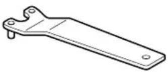
| 3 | Push button | 13 | Wrench |
| 4 | Side handle | 14 | With side guard (sold separately) |
| 5 | Gear cover | 15 | Abrasive cutting wheel (sold separately) |
| 6 | Depressed center wheel | 16 | Diamond wheel (sold separately) |
| 7 | Screw Off-lock lever | 17 | |
| 8 | Wheel guard Mesh | 18 | |
| 9 | Switch lever | 19 | Soft brush |
| 10 | Filter | ||
SYMBOLS
WARNING
The following show symbols used for the machine. Be sure that you understand their meaning before use.
| G10BYEQ2: Disc Grinder | |
 | To reduce the risk of injury, user must read instruction manual. |
 | Always wear eye protection. |
| V Rated voltage | |
| ~ | Alternating current |
| n | Rated speed |
| /min | Revolution or reciprocations per minute |
 | Switching ON |
 | Switching OFF |
 | Disconnect mains plug from electrical outlet |
 | Warning |
 | Class II tool |
STANDARD ACCESSORIES
In addition to the main unit (1 unit), the package contains the accessories listed in the below.
○ Wrench ....1
○ Side handle....1
○ Depressed center wheel ....1
Standard accessories are subject to change without notice.
APPLICATIONS
○ Removal of casting fin and finishing of various types of steel, bronze and aluminum materials and castings.
- Grinding of welded sections or sections cut by means of a cutting torch.
○ Grinding of synthetic resins, slate, brick, marble, etc.
○ Cutting of synthetic concrete, stone, brick, marble, and similar materials.
SPECIFICATIONS
| Model G10BYEQ2 | ||
| Voltage (by areas)*1 | (220 V, 230 V, 240 V)~ | |
| Power Input*1 | 220 V: 1200 W230-240 V: 1320 W | |
| Rated speed 10000 /min | ||
| Wheel | Outer dia. 100 mm | |
| Hole Dia. 16 mm | ||
| Thickness 6 mm | ||
| Peripheral speed 72 m/s | ||
| Weight(Only main body) | 1.6 kg | |
*1 Be sure to check the nameplate on product as it is subject to change by areas.
Electronic control
○ Soft start
Reduces recoil against the operator by managing the number of rotations during startup.
O 0 Voltage Re-start Protection
The 0 voltage restart protection feature prevents the power tool from restarting after the power has been temporarily cut off during operation.
○ Constant speed
○ Overload protection
This protection feature cuts off the power to the motor in the event of overloading of motor or a conspicuous reduction in rotational speed during operation.
When the overload protection feature has been activated, the motor may stop.
In this case, release the tool switch and eliminate causes of overloading.
After that you can use it again.
○ Rotation recovery control function
When the motor is stopped due to overloading, if the cause is eliminated, the motor automatically resumes operation.
During grinding, if the motor stops due to pressing too forcefully with the grinder, gently lift the tool body to start rotation again.
When the motor is stopped for a certain period of time, it does not recover, for the protection of the unit and for safety.
Turn it off once and on again to start it.
○ Overheat protection
This protection feature cuts off the power to the motor and stops the power tool in the event of overheating of motor during operation.
When the overheat protection feature has been activated, the motor may stop.
In this case, release the tool switch and cool it down in a few minutes.
After that you can use it again.
○ Brake function
Brake activates when the trigger is off.
○ Brake sytstem workable even in a power outage
The brake system works reliably even if there is a power outage or unplugging during operation in order to avoid unexpected accident.
NOTE
To prevent the tip tool from falling off, the brake will not be applied when the switch is released right after startup (within one second).
Due to HiKOKI's continuing program of research and development, the specifications herein are subject to change without prior notice.
MOUNTING AND OPERATION
| Action | Figure | Page |
| Fitting and adjusting the wheel guard | 2 | 2 |
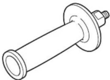
| Fixing the side handle | 3 | 2 |
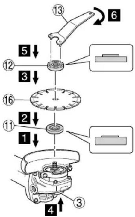
| Assembling depressed center wheel and diamond wheel*1 *2 | 4 | 3 |
| Assembling cutting wheel*1 *2 | 5 | 3 |
| Switch operation*3 | 6 | 4 |
| Grinding angle and grinding method | 7 | 4 |
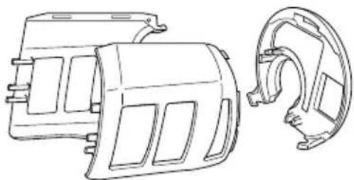
| Mounting and dismounting the filter set*4 | 9 | 4 |
| Selecting accessories | — | 45 |
*1 Sold separately
*2 WARNING
Before use, be sure to tighten the wheel nut with the included wrench.
Failure to tighten could result in the wheel nut loosening when the brake is activated during a stop.
NOTE
The wheel washer is specifically for this product. Do not use it for any other product.
*3 When the 0 voltage re-start protection feature has been activated, return the power switch to the OFF position and wait for 1 second or more before restarting the power tool.
*4 NOTE
○ When detaching the filter, be careful not to let debris enter the tool body.
- Keep the filter set attached except during cleaning or replacement.
MAINTENANCE AND INSPECTION
WARNING
Be sure to switch power OFF and disconnect the plug from the receptacle during maintenance and inspection.
- Inspecting the depressed center wheel
Ensure that the depressed center wheel is free of cracks and surface defects.
- Inspecting the mounting screws
Regularly inspect all mounting screws and ensure that they are properly tightened. Should any of the screws be loose, retighten them immediately. Failure to do so could result in serious hazard.
- Replacing supply cord
If the replacement of the supply cord is necessary, it has to be done by HiKOKI Authorized Service Center to avoid a safety hazard.
- Filter cleaning and inspection
WARNING
Wear protective glasses and a dust mask when cleaning the filter with an air blow gun.
Failure to do so may result in inhalation or exposure of the eyes to debris or dust.
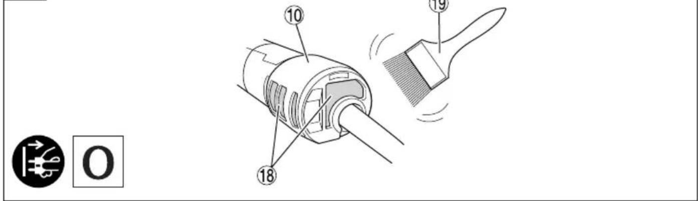
After use, remove any debris or dust adhered to the filter using a soft brush. (Fig. 8) Check the filter periodically to ensure that it is free of scratching, chipping, or tearing. Replace with a new filter if the filter is damaged in any way.
NOTE
If the mesh is clogged and the debris or dust cannot be removed, detach the filter and clean it with an air gun, etc. (See "Mounting and dismounting the filter set (Fig. 9)")
English
5. Maintenance of the motor
The motor unit winding is the very "heart" of the power tool. Exercise due care to ensure the winding does not become damaged and/or wet with oil or water.
NOTE
In order to expel debris and dust, periodically run the motor with no load.
CAUTION
In the operation and maintenance of power tools, the safety regulations and standards prescribed in each country must be observed.
NOTE
Due to HiKOKI's continuing program of research and development, the specifications herein are subject to change without prior notice.
一般安全規則

警告
閱讀所有安全警告說明
NAMA KOMPONEN (Gbr. 1–Gbr. 9)
| 1 | Motor | 11 | Cincin pelat batu gerinda (A) |
| 2 | Pelat nama Mur batu gerinda | ||
| 3 | Tombol tekan Kunci pas | 13 | |
| 4 | Pegangan samping | 14 | Dengan pelindung samping (dijual terpisah) |
| 5 | Penutup roda gigi | 15 | Batu gerinda pemotong (dijual terpisah) |
| 6 | Batu gerinda poles | 16 | Batu gerinda intan (dijual terpisah) |
| 7 | Sekrup Tuas off -lock | 17 | |
| 8 | Pelindung roda Kisi | 18 | |
| 9 | Tuas sakelar Sikat halus | 19 | |
| 10 | Filter | ||
SIMBOL
PERINGATAN
natural_image
Technical line drawing of a mechanical clamp or bracket (no text or symbols)100 mm : 301948
natural_image
Technical line drawing of a mechanical shaft with flange and bolt (no text or symbols)378279

100 mm : 373072

natural_image
Technical line drawing of a mechanical component with threaded end and flange (no text or symbols)336865

natural_image
Diagram of concentric circular layers with dot patterns, no text or symbols present
100 mm : 339578

natural_image
Technical line drawing of a mechanical component with curved and flanged sections (no text or symbols)100 mm : 302099
natural_image
Technical line drawing of a mechanical clamp or bracket (no text or symbols)100 mm : 313933
natural_image
Technical line drawing of an electric motor and its internal housing (no text or symbols)379204
natural_image
Line drawing of a quill pen with inkwell, no text or symbols present
natural_image
Line drawing of a quill pen with inkwell, no text or symbols presentKoki Holdings Co., Ltd.
Shinagawa Intercity Tower A, 15-1, Konan 2-chome, Minato-ku, Tokyo, Japan
- GENERAL POWER TOOL SAFETY WARNINGS
- WARNING
- 1) Work area safety
- 2) Electrical safety
- 3) Personal safety
- 4) Power tool use and care
- 5) Service
- PRECAUTION
- SAFETY WARNINGS COMMON FOR GRINDING OR ABRASIVE CUTTING-OFF OPERATIONS
- KICKBACK AND RELATED WARNINGS
- SAFETY WARNINGS SPECIFIC FOR GRINDING AND ABRASIVE CUTTING-OFF OPERATIONS
- ADDITIONAL SAFETY WARNINGS SPECIFIC FOR ABRASIVE CUTTING- OFF OPERATIONS
- GENERAL SAFETY INSTRUCTIONS FOR GRINDERS
- ADDITIONAL SAFETY WARNINGS
- English
- RCD
- SYMBOLS
- STANDARD ACCESSORIES
- APPLICATIONS
- Electronic control
- NOTE
- MAINTENANCE AND INSPECTION
- Maintenance of the motor
- CAUTION
- 一般安全規則
- 警告
- SIMBOL
- PERINGATAN
- Koki Holdings Co., Ltd.
Brand : HiKOKI
Model : G10BYEQ2
Category : Angle Grinder