
OneLINK Bridge Express - Audio/video converter Vaddio - Free user manual and instructions
Find the device manual for free OneLINK Bridge Express Vaddio in PDF.


| Product Type | Audio/Video Converter |
| Brand | Vaddio |
| Model | OneLINK Bridge Express |
| Power Supply | 48 VDC, 1.36 A (included) |
| HDBaseT Distance | Up to 100 m (328 ft) with Cat-6/7 cable |
| Video Output | HDMI 1.4b; USB 3.0 (uncompressed) |
| Audio Inputs | 2 balanced (Mic/Line level) |
| Audio Outputs | 2 balanced line-level |
| USB Streaming | USB 3.0 for soft conferencing |
| Network Control | Web interface, Telnet, RS-232 |
| Serial Control | RS-232 pass-through to camera |
| Supported Cameras | Vaddio HDBaseT cameras (e.g., RoboSHOT, RoboFLIP) |
| Phantom Power | 48 VDC for microphones (selectable) |
| Audio Processing | Acoustic echo cancellation, noise cancellation, AGC, filters |
| Mounting Options | Rack mount or under-table (kit sold separately) |
| Operating Temperature | 32°F to 104°F (0°C to 40°C) |
| Cleaning | Use soft cloth and lens cleaner; avoid abrasives |
| Warranty | Void if disassembled or wrong power supply used |
| Included Accessories | Power supply, user manual |
Frequently Asked Questions - OneLINK Bridge Express Vaddio
User questions about OneLINK Bridge Express Vaddio
0 question about this device. Answer the ones you know or ask your own.
Ask a new question about this device
Download the instructions for your Audio/video converter in PDF format for free! Find your manual OneLINK Bridge Express - Vaddio and take your electronic device back in hand. On this page are published all the documents necessary for the use of your device. OneLINK Bridge Express by Vaddio.
USER MANUAL OneLINK Bridge Express Vaddio
Complete Manual for the
OneLINK Bridge Express
AV Interface
Document 411-0062-30 Rev A March 2022
Contents
Overview ...1
What's in this Guide...1
Features ...1
A Quick Look at the OneLINK...Device...2
Front Panel of the Receiver...2
Connector Panel of the Receiver...2
Installing the OneLINK Device...3
Don't Void Your Warranty!...3
Cabling Notes...3
RS-232 Connector Pin-Out...4
Mounting the OneLINK Device...4
About Installations Using Half-Recessed Ceiling Mounts...4
Connections for HDBaseT Cameras...5
Connections for HDBaseT Cameras Used with ...Codecs...6
Connecting a Vaddio HDBaseT Camera and Polycom...Codec...6
Connecting a Vaddio HDBaseT Camera and Cisco Codec 7
Hardware Note: Connections and Configuration Changes 10
OneLINK Device Configuration for Audio Using a...Codec 10
Powering Up the Equipment 10
Web Interface 11
Working with the Connected Camera 11
Compatible Web Browsers 11
Initial Device Set-Up and System Administration Tasks 12
Initial Device Set-Up Using the Vaddio Device Controller 12
Initial Device Set-Up Using the Vaddio Deployment Tool 12
Accessing the Web Interface Manually 13
If the Device Is At 169.254.10.1...13
Completing the Initial Device Set-up 14
System Administration 15
Configuring Access and Other Security Settings 15
Configuring a Static IP Address for a Device Currently at 169.254.10.1 16
Changing from an Automatically Assigned Address to a Static IP Address. 17
Changing the Device's Hostname 17
Specifying Time Zone and NTP Server 18
Adding Room Information to the Web Interface 18
Serial Control Settings 19
Accessing the Connected Camera's Web Interface 19
Performance and Behavior Settings 20
Configuring USB Streaming Settings 20
Configuring Audio Settings 21
Quick Adjustments - Muting and Volume 21
Enabling Phantom Power to Microphones 22
Reading the Audio Matrix 23
Routing Audio 23
Default Microphone Settings 24
Microphone Settings for Environments with Audiences 24
Microphone Adjustments 25
Speaker Adjustments 26
About Echo Cancellation 27
Preventing Audio Feedback 27
System Maintenance 28
Exporting and Importing Configuration Data 28
Starting a Firmware Update 29
Rebooting the OneLINK Device 29
Contacting Vaddio Technical Support and Viewing Diagnostics 30
Serial Command API 31
Audio Management Commands 32
Channels Available for Audio Commands 32
audio volume 33
audio mute 33
audio route 34
audio crosspoint-gain 34
Communication and Power Commands 35
network settings get 35
link power 35
Maintenance and Troubleshooting Commands 36
version 36
network ping 36
system reboot 37
system factory-reset 37
Telnet Information and Session Management Commands 38
history 38
help 38
exit 38
Troubleshooting 39
Power Issues 39
Communication Issues 40
Video and Audio Issues 40
Restoring Factory Defaults 41
Operation, Storage, and Care 41
Index 42
Overview
This guide covers the OneLINK™ Bridge Express AV Interface:
■ 999-9595-070 - OneLINK Bridge Express, North America
■ 999-9595-071 - OneLINK Bridge Express, Europe and UK
■ 999-9595-079 - OneLINK Bridge Express, Australia and New Zealand
The OneLINK Bridge Express AV interface is also available as a component of several kits and systems.

What's in this Guide
This guide provides information about:
■ Physical features
■ Installation
■ System administration and configuration
■ Serial API for third-party control
■ Troubleshooting and maintenance
For your convenience, the information you need to install this product is also available in the sn stand-alone Installation Guide for the OneLINK Bridge Express AV Interface, which covers physical features, installation, and initial power-on.
Features
■ Compatible with Vaddio HDBaseT™ cameras and other compliant HDBaseT sources
■ Simple, clutter-free camera installation – power, control, video, and streaming over one cable
■ Extends camera installation distance up to 100 m (328 ft.) using Cat-6 cable
■ Administrative control via web interface
■ Passes web, Telnet, and RS-232 serial control to connected devices
■ Converts any conference room to a BYOD environment, connecting professional AV equipment and delivering a USB 3.0 stream for soft-conferencing clients
■ Simultaneous uncompressed USB 3.0 and HDMI 1.4b; passes IP stream if available from source
■ Two balanced audio inputs, line level or mic level; two balanced audio outputs, line level
■ Kits available for use with Polycom and Cisco codecs
A Quick Look at the OneLINK Device
This section covers the physical features of the OneLINK Bridge Express AV interface.
Front Panel of the Receiver

- USB light - On when a USB stream is active.
■ Network light – On when connected to the IP network.
■ Source light - On when a video input is detected. - Display IP and MAC Address button (illuminated blue) – Displays the OneLINK Bridge IP and addresses as an overlay on all video outputs.
■ Power System Reset button (illuminated red) – reboots the device. This does not affect the connected camera.
Connector Panel of the Receiver

From the left:
■ Power input jack - Connect the supplied 48 VDC, 1.36 A power supply.
- OneLINK interface port - Connection to the HDBaseT camera: video, audio (if available), network connectivity including H.264 IP streaming from the camera (if available), RS-232 control, and 12 camera power.
■ HDMI output – Connection for a display.
- USB 3.0 - Connect to a computer for uncompressed video output with PCM audio for confer applications.
■ Network port – Web interface access, H.264 IP streaming (if available from the camera), and third-party IP control via Telnet API.
■ RS-232 port – Connection for a camera controller or third-party control system.
■ Audio I/O Line Out 1 and Line Out 2 – Far-end audio from conferencing application or as configured in the audio matrix.
■ Audio I/O Mic/Line In 1 and Mic/Line In 2 – Connections for microphones or other audio in
Installing the OneLINK Device
This section covers:
■ Things to know before you start the installation
■ Basic connection examples
Don't Void Your Warranty!
Caution
Use only the power supply included with this product. Using a different one will void the warrant could create unsafe operating conditions or damage the product.
Do not connect the OneLINK power supply to a Vaddio camera. It does not provide the correct Vaddio cameras, and will damage the camera and void the camera's warranty.
This product is for indoor use only. Do not install it outdoors or in a humid environment. Do not come into contact with any liquid. Do not install or operate this product if it has been dropped, or exposed to liquids. If any of these things happen, return it to Vaddio for safety and function
Note
Disassembling this product will void the warranty.
Cabling Notes
■ Maximum cable distance between the OneLINK device and the camera is 328 ft (100 m) using or Cat-7 cable, or 230 ft (70 m) using Cat-5e cable.
- Cat-6 or Cat-7 cabling allows longer maximum cabling distance, and may provide better perform in noisier RF or EMF environments.
■ We recommend shielded cabling if the cables will be coiled, run tightly with other cables, or near sources of electromagnetic interference such as power lines or fluorescent light fixtures. WI in doubt, use shielded Cat-6 cable.
Caution
When making cables for Vaddio products, do not use pass-through RJ-45 connectors. If they are crimped incorrectly, they can damage the connectors on the products cause intermittent connections, and degrade signal quality. Physical damage to the connectors will void your warranty.
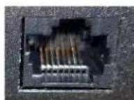
Intact
Contact fingers will make re contact with the cable conn

Damaged
Some contact fingers are bent and will NOT make reliable contact with the cable connector
We recommend using high-quality connectors and a high-quality crimping tool.

Pro Tip
To prevent tragic mishaps, label both ends of every cable.
RS-232 Connector Pin-Out
The OneLINK device passes signals from a third-party device to the connected camera.

OneLINK Receiver - RS-232 Control Port
| Pin | Signal |
| 1 | (not used) |
| 2 | (not used) |
| 3 | (not used) |
| 4 | (not used) |
| 5 | (not used) |
| 6 | GND |
| 7 | RX (from TX of controller) |
| 8 | TX (to RX of controller) |
Mounting the OneLINK Device
Rack and under-table mounting kits are available for the receiver. Follow the mounting instructions supplied with the kit.
About Installations Using Half-Recessed Ceiling Mounts
If the connected camera is mounted in an In-CEILING Half-Recessed Ceiling Mount for RoboSHOT series cameras, and the mount's IR receiver will be used to forward commands to the camera, be powered separately using Power Extension Module 998-2225-051. Cameras powered by OneLINK devices cannot supply power to the mount's IR receiver.
Connections for HDBaseT Cameras
The OneLINK Bridge Express extends network connectivity, power, and control to an HDBaseT can and sends HDMI video from the camera to a display. In addition, the device provides audio con and originates a USB stream to bridge the equipment into a USB-based conferencing application.
The camera can optionally be controlled by a camera controller via the OneLINK connection. Depo on the equipment, the camera controller may connect directly to the OneLINK device's RS-232 port may control the camera over the network. In either case the OneLINK device passes communicati between the controller and the camera.
If an IP stream is available from the camera, the OneLINK device passes it to the network. Et through is limited to 100 Mb/s. HDMI output resolution and streaming parameters (including resolution) are configured on the camera, not the OneLINK device.
The RoboSHOT HDBT, RoboSHOT UHD, RoboFLI and RoboSHOT In-Wall models are HDBaseTcameras.
This diagram shows a RoboFLIP 30 HDBT camera. Other Vaddio HDBaseT cameras connect in the same way.

flowchart
graph TD
    A["OneLINK"] -->|USB 3| B["Network"]
    B --> C["Audio"]
    C --> D["Audio"]
    D --> E["Video"]
    E --> F["Power"]
    F --> G["USB 1.3"]
    G --> H["OneLINK"]
    H --> I["48 VDC 1.30 AMP"]
    I --> J["USB 1.3"]
    J --> K["OneLINK"]
    K --> L["48 VDC 1.30 AMP"]
    L --> M["OneLINK"]
    M --> N["48 VDC 1.30 AMP"]
    N --> O["OneLINK"]
    O --> P["48 VDC 1.30 AMP"]
    P --> Q["OneLINK"]
    Q --> R["48 VDC 1.30 AMP"]
    R --> S["OneLINK"]
    S --> T["48 VDC 1.30 AMP"]
    T --> U["OneLINK"]
    U --> V["48 VDC 1.30 AMP"]
    V --> W["OneLINK"]
    W --> X["48 VDC 1.30 AMP"]
    X --> Y["OneLINK"]
    Y --> Z["48 VDC 1.30 AMP"]
Connections for HDBaseT Cameras Used with Codecs
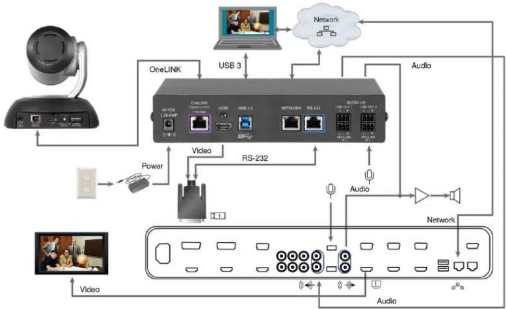
A codec may be connected to the OneLINK device via RS-232 or over the IP network, depending on codec.
If an IP stream is available from the camera, the OneLINK device passes it to the network. Et through is limited to 100 Mb/s. HDMI output resolution and streaming parameters (including resolution) are configured on the camera, not the OneLINK device.
Connecting a Vaddio HDBaseT Camera and Polycom Codec
These diagrams show a OneLINK Bridge AV interface with a RoboSHOT HDBT camera. The OneLI Bridge Express connects in the same way. Other Vaddio HDBaseT cameras connect in the same The Polycom RealPresence Group 500 codec is similar to the RealPresence Group 310 codec, ar connects to the OneLINK device in the same way.
RoboSHOT HDBT Camera and Polycom RealPresence Group 310 Codec

flowchart
graph TD
    A["OneLINK"] -->|USB 3| B["OneLink"]
    B --> C["RS-232"]
    C --> D["Audio HD"]
    D --> E["Network"]
    E --> F["Audio"]
    F --> G["Video"]
    G --> H["Power"]
    H --> I["RS-232"]
    I --> J["Audio"]
    J --> K["Audio"]
    K --> L["Network"]
    L --> M["Audio"]
    M --> N["Video"]
    N --> O["RS-232"]
    O --> P["Audio HD"]
    P --> Q["Network"]
    Q --> R["Audio HD"]
    R --> S["OneLINK"]
    S --> T["OneLINK 1.86AMP"]
    T --> U["OneLINK 1.86AMP"]
    U --> V["OneLINK 1.86AMP"]
    V --> W["OneLINK 1.86AMP"]
    W --> X["OneLINK 1.86AMP"]
    X --> Y["OneLINK 1.86AMP"]
    Y --> Z["OneLINK 1.86AMP"]
    Z --> AA["OneLINK 1.86AMP"]
    AA --> AB["OneLINK 1.86AMP"]
    AB --> AC["OneLINK 1.86AMP"]
    AC --> AD["OneLINK 1.86AMP"]
    AD --> AE["OneLINK 1.86AMP"]
    AE --> AF["OneLINK 1.86AMP"]
RoboSHOT HDBT Camera and Polycom RealPresence Group 700 Codec
flowchart
graph TD
    A["OneLINK"] -->|USB 3| B["USB 3.0"]
    B --> C["48 VDC"]
    C --> D["RS-232"]
    D --> E["Audio"]
    E --> F["Network"]
    F --> G["Audio"]
    G --> H["Video"]
    H --> I["Power"]
    I --> J["OneLINK"]
    J --> K["OneLINK"]
    K --> L["USB 3.0"]
    L --> M["48 VDC"]
    M --> N["RS-232"]
    N --> O["Audio"]
    O --> P["Network"]
    P --> Q["Audio"]
    Q --> R["Video"]
    R --> S["OneLINK"]
    S --> T["OneLINK"]
    T --> U["USB 3.0"]
    U --> V["48 VDC"]
    V --> W["RS-232"]
    W --> X["Audio"]
    X --> Y["Network"]
    Y --> Z["Audio"]
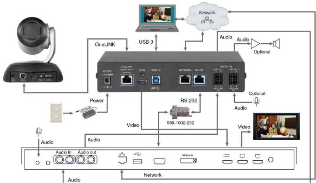
Connecting a Vaddio HDBaseT Camera and Cisco Codec
RoboSHOT HDBT Camera and Cisco C20 Codec
This diagram shows a OneLINK Bridge AV interface with a RoboSHOT HDBT camera. The OneLIN Bridge Express connects in the same way. Other Vaddio HDBaseT cameras connect in the same
flowchart
graph TD
    A["OneLINK"] -->|USB 3| B["OneLINK"]
    B --> C["RS-232"]
    C --> D["998-1002-232"]
    D --> E["Audio"]
    E --> F["Audio In"]
    E --> G["Audio Out"]
    F --> H["Audio"]
    G --> I["Audio"]
    J["Network"] --> K["Optional"]
    L["Audio"] --> M["Optional"]
    N["Power"] --> O["Power Input"]
    P["Video"] --> Q["Video In"]
    R["Video"] --> S["Video Out"]
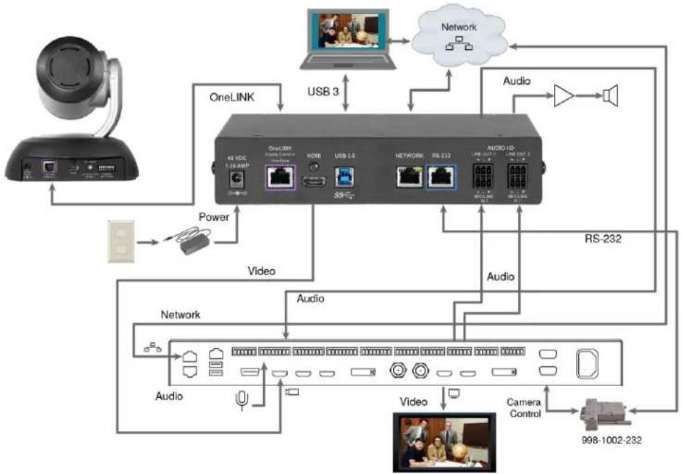
RoboSHOT HDBT Camera and Cisco C60 Codec
This diagram shows a OneLINK Bridge AV interface with a RoboSHOT HDBT camera. The OneLIN Bridge Express connects in the same way. Other Vaddio HDBaseT cameras connect in the same The Cisco C40 codec looks similar and connects in the same way.

flowchart
graph TD
    A["OneLINK"] -->|USB 3| B["OneLINK"]
    B --> C["USB 2.3"]
    C --> D["Network"]
    D --> E["Audio"]
    E --> F["Optional"]
    F --> G["Video"]
    G --> H["OneLINK"]
    H --> I["OneLINK"]
    I --> J["USB 2.3"]
    J --> K["Network"]
    K --> L["Audio Line In"]
    K --> M["Audio Line Out"]
    L --> N["RS-232"]
    M --> O["Camera Control"]
    N --> P["998-1002-232"]
    O --> Q["RS-232"]
    style A fill:#f9f,stroke:#333
    style B fill:#ccf,stroke:#333
    style C fill:#ccf,stroke:#333
    style D fill:#ccf,stroke:#333
    style E fill:#ccf,stroke:#333
    style F fill:#ccf,stroke:#333
    style G fill:#ccf,stroke:#333
    style H fill:#cfc,stroke:#333
    style I fill:#cfc,stroke:#333
    style J fill:#cfc,stroke:#333
    style K fill:#cfc,stroke:#333
    style L fill:#cfc,stroke:#333
    style M fill:#cfc,stroke:#333
    style N fill:#cfc,stroke:#333
    style O fill:#cfc,stroke:#333
    style P fill:#cfc,stroke:#333
    style Q fill:#cfc,stroke:#333
RoboSHOT HDBT Camera and Cisco SX20 Codec
This diagram shows a OneLINK Bridge AV interface with a RoboSHOT HDBT camera. The OneLIN Bridge Express connects in the same way. Other Vaddio HDBaseT cameras connect in the same

flowchart
graph TD
    A["OneLINK"] -->|USB 3| B["OneLINK 1.5GAM"]
    B --> C["USB 1.0"]
    C --> D["RS-232"]
    D --> E["Audio IO"]
    E --> F["RS-232"]
    F --> G["Video"]
    G --> H["Video"]
    H --> I["Audio"]
    I --> J["Network"]
    J --> K["Audio"]
    K --> L["Power"]
    L --> M["OneLINK"]
    M --> N["OneLINK 1.5GAM"]
    N --> O["USB 1.0"]
    O --> P["RS-232"]
    P --> Q["Audio IO"]
    Q --> R["RS-232"]
    R --> S["Video"]
    S --> T["Audio"]
    T --> U["Network"]
Note
If connecting to a Cisco SX20 codec, you will need to provide a Cisco split cable, Cisco part CAB-PHD4XS2-SPLIT.
RoboSHOT HDBT Camera and Cisco SX80 Codec
This diagram shows a OneLINK Bridge AV interface with a RoboSHOT HDBT camera. The OneLIN Bridge Express connects in the same way. Other Vaddio HDBaseT cameras connect in the same
flowchart
graph TD
    A["OneLINK"] -->|USB 3| B["Audio"]
    B --> C["RS-232"]
    C --> D["Video"]
    D --> E["OneLINK"]
    E --> F["OneLINK"]
    F --> G["OneLINK"]
    G --> H["OneLINK"]
    H --> I["OneLINK"]
    I --> J["OneLINK"]
    J --> K["OneLINK"]
    K --> L["OneLINK"]
    L --> M["OneLINK"]
    M --> N["OneLINK"]
    N --> O["OneLINK"]
    O --> P["OneLINK"]
    P --> Q["OneLINK"]
    Q --> R["OneLINK"]
    R --> S["OneLINK"]
    S --> T["OneLINK"]
    T --> U["OneLINK"]
    U --> V["OneLINK"]
    V --> W["OneLINK"]
    W --> X["OneLINK"]
    X --> Y["OneLINK"]
    Y --> Z["OneLINK"]
    Z --> AA["OneLINK"]
    AA --> AB["OneLINK"]
    AB --> AC["OneLINK"]
    AC --> AD["OneLINK"]
    AD --> AE["OneLINK"]
    AE --> AF["OneLINK"]
    AF --> AG["OneLINK"]
    AG --> AH["OneLINK"]
    AH --> AI["OneLINK"]
    AI --> AJ["OneLINK"]
    AJ --> AK["OneLINK"]
    AK --> AL["OneLINK"]
    AL --> AM["OneLINK"]
    AM --> AN["OneLINK"]
    AN --> AO["OneLINK"]
    AO --> AP["OneLINK"]
    AP --> AQ["OneLINK"]
    AQ --> AR["OneLINK"]
    AR --> AS["OneLINK"]
    AS --> AT["OneLINK"]
    AT --> AU["OneLINK"]
    AU --> AV["OneLINK"]
    AV --> AW["OneLINK"]
    AW --> AX["OneLINK"]
    AX --> AY["OneLINK"]
    AY --> AZ["OneLINK"]
    AZ --> BA["OneLINK"]
    BA --> BB["OneLINK"]
    BB --> BC["OneLINK"]
    BC --> BD["OneLINK"]
    BD --> BE["OneLINK"]
    BE --> BF["OneLINK"]
    BF --> BG["OneLINK"]
    BG --> BH["OneLINK"]
    BH --> BI["OneLINK"]
    BI --> BJ["OneLINK"]
    BJ --> BK["OneLINK"]
    BK --> BL["OneLINK"]
    BL --> BM["OneLINK"]
    BM --> BN["OneLINK"]
    BN --> BO["OneLINK"]
    BO --> BP["OneLINK"]
    BP --> BQ["OneLINK"]
    BQ --> BR["OneLINK"]
    BR --> BS["OneLINK"]
    BS --> BT["OneLINK"]
    BT --> BU["OneLINK"]
    BU --> BV["OneLINK"]
    BV --> BW["OneLINK"]
    BW --> BX["OneLINK"]
    BX --> BY["OneLINK"]
    BY --> BZ["OneLINK"]
Hardware Note: RS-232 Connections
For RS-232 connections to Cisco gear using DE-9 connectors, use the 998-1002-232 RJ-45 to DE adapter. Its wiring differs from the 998-1001-232 adapter used with many Vaddio products.
For RS-232 connections to Cisco gear using the Cisco split cable, use the appropriate null-modem to the RJ-45 side of the split cable. Connect the null-modem cable as indicated on the cable I
Hardware Note: Connections and Configuration Changes
After configuring the equipment, reboot the OneLINK device, camera, and codec individually. Reboot the OneLINK device does not affect the camera and codec.
If you connect a camera or other device while it has power, reboot the OneLINK device and the connected device.
OneLINK Device Configuration for Audio Using a Codec
After installation is complete and the OneLINK device and camera are operational, you will need change the AEC reference if you made the audio connections as shown in these diagrams. Set Output/AEC Reference to Output 2 if using Line Out 2 for the speaker connection. See Preventing Audio Feedback.
Powering Up the Equipment
Power up the connected equipment that is not powered by the OneLINK device (such as display: third-party control devices), then connect power to the OneLINK device. The connected camera and OneLINK device power up together.
Web Interface
The OneLINK device provides a web interface to allow configuration and administration using a br. The web interface allows you to:
■ Set idle session behavior and passwords
■ Manage streaming settings
■ Add identifying information to the web interface
■ Back up, reboot, reset, or update the device
■ View information about the camera connection
■ View network-related information
■ View information about the device's firmware and current settings
Many of the screen shots in this manual are from the OneLINK BridgeAV interface, which has capabilities that are not available in the OneLINK Bridge Express device.
Working with the Connected Camera
The OneLINK device is not a camera control device. To operate the camera, use the camera's interface. You can access this from the Pairing page. Refer to the camera's documentation for de The connected camera is configured separately from the OneLINK device. Changes to the OneLINK device's configuration do not affect the configuration of the camera or other connected equipment. need to change the way the camera is configured, log in to the camera's web interface.
Compatible Web Browsers
We have tested this product with these web browsers:
Chrome®
■ Firefox®
■ Microsoft® Internet Explorer®
Safari®
We test using the browser version available from the vendor at that time. Older versions of these browsers are likely to work, and other browsers may also work.
Initial Device Set-Up and System Administration Tasks
When any Vaddio product is shipped from the factory, there is no admin password and the adm controls are not available. You will need to access the web interface and set the admin passwo gives you access to the administrative controls.
Initial Device Set-Up Using the Vaddio Device Controller
The Vaddio Device Controller is a stand-alone tablet for working with Vaddio products' web interface. To complete the initial device set-up with the Vaddio Device Controller:
-
Connect the touch-panel to the network on the same subnet as the products you need to w for example, connect both to the same PoE+ switch.
-
Go to the touch-panel's Configuration page (gear icon) and select Scan.
-
Locate the device you need to work with, and select Use.
-
Select Exit to leave the Configuration page and open the device's web interface.
Note
The first time you access a device at a specific IP address, the Vaddio Device Controller's s may remain blank for 20 seconds or more.
- Set the admin password. This logs you in.
If the Vaddio Device Controller does not find the device, verify that the Vaddio Device Controller device are connected to the same subnet. You may need to access the web interface manually.
Initial Device Set-Up Using the Vaddio Deployment Tool
Be sure you have the current version of the Vaddio Deployment Tool. If you have a copy of already, compare its version information to the version shown on the release notes. You can find https://www.legrandav.com/en/products/vaddio/accessories/vaddio_deployment_tool. Release notes are under the Resources tab.
To complete the initial device set-up with the Vaddio Deployment Tool:
-
Download and install the Vaddio Deployment Tool if you have not done so already, then ope
-
Power up the OneLINK device if you have not done so already.
-
On the Find Devices page, click Scan. If the scan does not locate the device, your compute on a different subnet. Click Advanced and specify the appropriate portion of the network to so
-
In the list of equipment that the scan discovers, locate the devices marked Not Set Up.
| Name | Location | IP / Hostname | Firmware | Status | Video |
| RoboSHOT 12E HD-SDI Camera | Karen | 10.30 219.51 [7] | 3.3.0 | PasswordLogin | *** |
| RoboSHOT 12E HDMI Camera | Very Large University Dept of Theoretical Enphasis | 10.30 219.54 [7] | 3.4.1 | PasswordLogin | *** |
| OneLINK HDMI Camera Extension | 10.30 219.56 [7] | 1.2.1 | PasswordLogin | *** | |
| RoboSHOT 12E Camera | 10.30 219.54 [7] | 3.3.0 | PasswordLogin | *** | |
| RoboSHOT 20 UHD Camera | 10.30 219.05 [7] | 2.4.0 | PasswordLogin | *** | |
| OneLINK Bridge Camera Extension | 10.30 219.05 [7] | 1.5.1 | Not set up | *** |
- For each device that you need to work with, click the Not Set Up button and set the adm on the device detail page that opens. Other people using the Vaddio Deployment Tool then h option to log in, as shown for the other devices in the screen shot.
You can use the Vaddio Deployment Tool to access the web interface of any device in the device is set up and you have provided the admin password.
If the Vaddio Deployment Tool cannot discover the OneLINK device, you may need to access the web interface manually.
Accessing the Web Interface Manually
To get the IP address:
Press the button labeled Display IP and MAC Address, on the front of the unit. The information on the video outputs.
The OneLINK device uses the default address of 169.254.10.1 if no DHCP server is available. In situation, you will need to connect a computer to the OneLINK device's network port and config network settings.
To access the web interface:
Enter the IP address in your browser's address bar. You may need to enter https://as a prefix to keep the browser from treating it as a search query.
After the device is set up, you can access its web interface by its hostname instead of its IP
If the Device Is At 169.254.10.1
This is the device's default IP address. This means one of these things:
- The device is not connected to the network – check the cable connected to the Network port - The network does not automatically assign IP addresses, and you need to configure the device the network.
To communicate directly with the device:
Connect a cable from your computer's network port to the device's network port. You do not ne disconnect other devices.
After completing the initial device set-up, you will need to configure the device with a static IP Work with your network administrator.
Completing the Initial Device Set-up
Set the admin password and complete any other required tasks, such as accepting agreements. T administrative interface opens when you finish.

Note
The web interface provides links to the company's standard privacy policy because the device's IF address is considered "personally identifiable information". This product does not record or save audio video files, and it does not store any identifying information other than what you may choose to the Room Labels page of the web interface.
You may also need to complete the initial device set-up and administrative configuration on the connected camera.
System Administration
Administrative tasks are on these pages of the web interface:
■ Networking – Network configuration, time zone and NTP server
■ Security – Passwords, guest access, other IT security-related settings
■ Room Labels – Helpful information to display in the web interface
Some of the screen shots in this manual are from other OneLINK products, and may differ some from the web interface that you see.
Configuring Access and Other Security Settings
SECURITY PAGE
The Account Passwords and Web Server areas of the Security page provide basic security for the interface:
- Admin Password – Required for access to the admin pages of the web interface and for ser access (via Telnet session or RS-232 connection) to the device.
■ Automatically Expire Idle Sessions – Logs you out after 30 minutes of inactivity. - Allow Telnet Access – disabled by default.
- Allow Zeroconf DNS-SD Discovery – allowed by default.
■ Advanced Settings – Enable HTTP Access (disabled by default) and Manage SSL Certificate.
Note
Consult your network security specialist before changing any of these settings. Seek explicit guidance concerning the SSL certificate.

Configuring a Static IP Address for a Device Currently at 169.254.10.1
NETWORKING PAGE
These settings are for the OneLINK device only. The camera is configured separately. If the device is currently at an IP address other than 169.254.10.1, skip this section.
By default, the device is set to DHCP, and will receive an IP address automatically if you network assigns IP addresses. However, if no DHCP server is available to automatically assign an address, the device uses its default IP address of 169.254.10.1. If you install more than one Or device on a non-DHCP network, you must follow this procedure to prevent IP address conflicts.
Caution
Consult your IT department before editing network settings. Errors in network configuration can make device inaccessible from the network. Do not change DHCP/Static addressing, IP address, subnet or gateway unless you are very familiar with the characteristics and configuration of the network you install the device.
To access the device's Networking page after initial device setup:
- Leave the device connected as for initial device setup.
- Log in to the web interface, if you have not done so already.
- On the Networking page, set IP Address to Static; then enter the IP address, subnet mask, gateway as directed by the network specialist. You will need to log in again after saving you. The device is now ready to be connected to the network.

Changing from an Automatically Assigned Address to a Static IP Address
NETWORKING PAGE
In a network that assigns IP addresses automatically, the device's IP address may change from time. Setting a static IP address will keep this from happening,
You may wish to change the IP addresses of other connected equipment to static addresses as process is the same for all Vaddio products with web interfaces.
- Consult your network specialist to determine what the IP address should be.
- Set the IP address to Static. If this is the only change you make, you will not be logged
- If necessary, enter the IP address, subnet mask, and gateway that your network specialist inst you to use. You will need to browse to the new IP address and log in again.
Changing the Device's Hostname
NETWORKING PAGE
If your network supports hostname resolution, you may find it convenient to change the device's hostname to something easy to remember. This allows you to access the device by its hostname of its IP address – for example, by entering https://fred to open the web interface of the device named fred.

Work with your IT department to ensure that the hostname conforms to the organization's naming conventions.
Specifying Time Zone and NTP Server
NETWORKING PAGE
Using automatic NTP updating ensures that the timestamps in the device's diagnostic log are acc. Specifying your time zone may make it easier to match logged events with other actions and e> events.
- To make the time zone and NTP server editable, enable Automatic NTP Updating.
- Select the desired time zone from the list.
- Optional: Specify the NTP server to use. If you are not sure about this, use the default.
-
Save your changes.
-
To update the system time immediately, select Refresh. Otherwise, the time will update the next device contacts the NTP server.

Adding Room Information to the Web Interface
ROOM LABELS PAGE
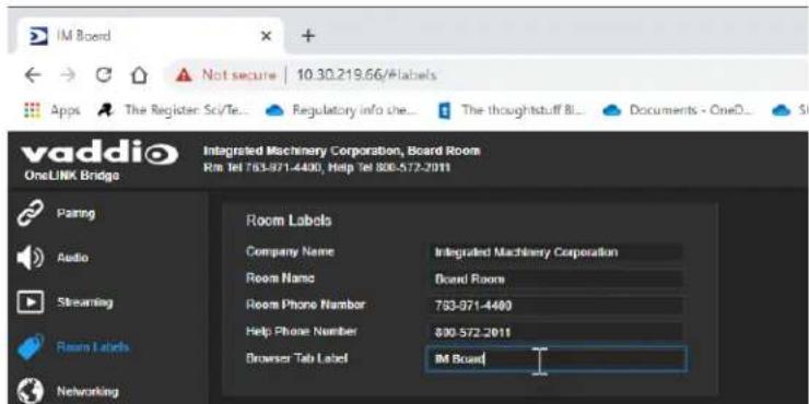
Enter information about the location of the equipment and the local IT or A/V help line. This in will be displayed on all pages of the web interface.
Note
This does not affect the room information (if any) presented on the web interface for the attached camera.
Serial Control Settings
Enhanced VISCA Mode - Enabled by default; provides enhanced support for some capabilities in HDBaseT cameras.
Baud Rate – If the installation includes devices that use RS-232 communication, set them all to use the same baud rate.

Accessing the Connected Camera's Web Interface
The Pairing page provides a link to the connected HDBaseT camera's web interface. You can also access the camera's web interface using the Vaddio Deployment Tool or a Vaddio Device Control the room includes one).

Performance and Behavior Settings
Performance and behavior settings are on these pages of the web interface:
■ Streaming - USB streaming settings
■ Audio – Audio adjustments; phantom power to connected microphones; audio matrix
The screen shots in this chapter are from the OneLINK Bridge, and may differ somewhat from 1 interface that you see.
Configuring USB Streaming Settings
STREAMING PAGE
The camera's settings are used for IP streaming; the OneLINK device passes the IP stream from camera and does not require additional IP streaming configuration.
For non-USB cameras, the OneLINK device provides USB streaming capability.
These settings affect how the camera works with soft conferencing applications.
■ Enable USB Streaming – The OneLINK device can originate a USB stream only when this is selected.
■ USB Device Name – Specify how the camera shows up in your soft client's camera selection list.
■ HID Audio Controls – Enable to allow conferencing applications to control the audio.
■ Enable UVC Extensions – Allow conferencing applications to control the camera.

Note
When HID Audio Controls are enabled, the conferencing application manages the volume automatica If necessary, you can disable HID Audio Controls to control volume manually.
Configuring Audio Settings
AUDIO PAGE
The web interface provides separate controls for each of the audio inputs and outputs:
■ Analog (Mic/Line In 1 and 2, and Line Out 1 and 2)
■ Digital (HDBT Input left and right, HDMI Output left and right
- Streaming (USB Playback left and right, HDBT Output left and right, USB Record left and right The Matrix tab of the Audio page defines audio routing.
Quick Adjustments – Muting and Volume
AUDIO PAGE, ANALOG, DIGITAL, AND STREAMING TABS
To mute all microphones:
Use the Mute control at the top of any page.

To control volume on individual inputs or outputs:
Use the button to mute the desired audio input or output. Use the slider to set the volume.

Note
For best performance with most computers, we recommend setting the USB Record volume high.
Enabling Phantom Power to Microphones
AUDIO PAGE, ANALOG TAB
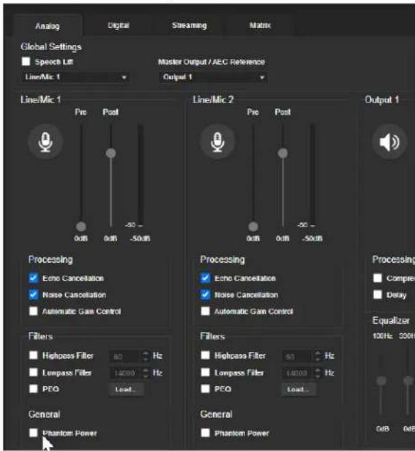
To supply 48 VDC phantom power to a connected microphone, check the Phantom Power checkb below the controls for the Line/Mic input.
Reading the Audio Matrix
AUDIO PAGE, MATRIX TAB
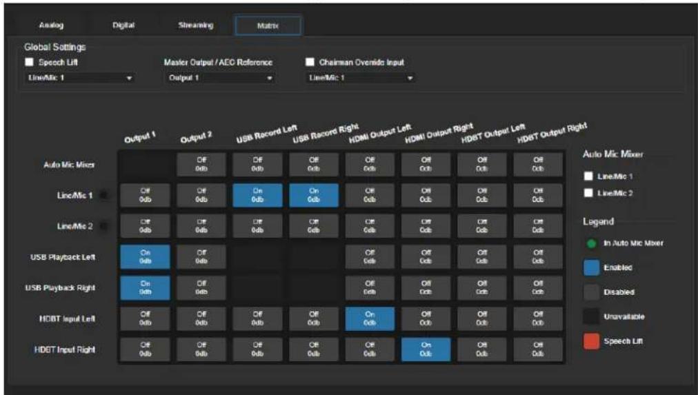
The audio matrix shows where each audio output originates. Each column of the matrix shows or output, and each row shows one audio input. Table cells highlighted in blue mean that the input represented in that row is routed to the output represented in that column. More than one input routed to a given output. The defaults are:
■ USB Playback left and right (far-end audio from the soft conferencing client) route to line output 1 (typically the speaker in your conference room).
■ Line/Mic 1 (your room's microphone) routes to USB Record left and right (the audio that the participants on the far end hear).
■ HDBT left and right (far-end audio received as part of the HDMI signal over the HDBT connection) routes to HDMI Output left and right, and goes to the HDMI display's speakers.
Routing Audio
AUDIO PAGE, MATRIX TAB
To specify how the OneLINK Bridge uses a given audio input, locate its row. Locate the column representing the desired output and select the table cell where the desired row and column interests. Example: The USB stream has left and right audio channels, but by default Line/Mic 1 provides source for both channels of outbound USB audio (USB Record left and right) and both channels incoming USB audio are routed to Output 1 (Audio Line Out 1). You might choose to change matrix to provide separate right and left channels of outbound and inbound USB audio.
Default Microphone Settings
AUDIO PAGE, ANALOG TAB
Acoustic Echo Cancellation – Enabled; prevents audio feedback by cancelling the specified output signal out of the line/mic input.
Note
If using the OneLINK Bridge with a conferencing codec, ensure that echo cancellation is enabled one device, whether it is the OneLINK Bridge or the codec. If echo cancellation is enabled on OneLINK Bridge and the codec, unexpected audio effects may result. We recommend disabling echo cancellation on the OneLINK Bridge and allowing the conferencing codec to handle it.
Noise Cancellation - Enabled; suppresses ambient noise.
Automatic Gain Control – Disabled; adjusts gain to compensate for differences in volume as different people speak.
Microphone Settings for Environments with Audiences
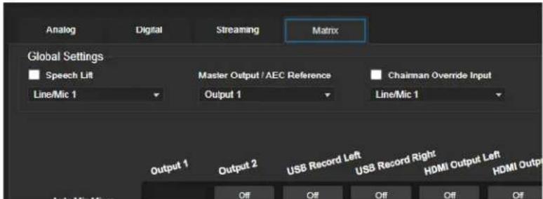
AUDIO PAGE, ANALOG AND MATRIX TABS
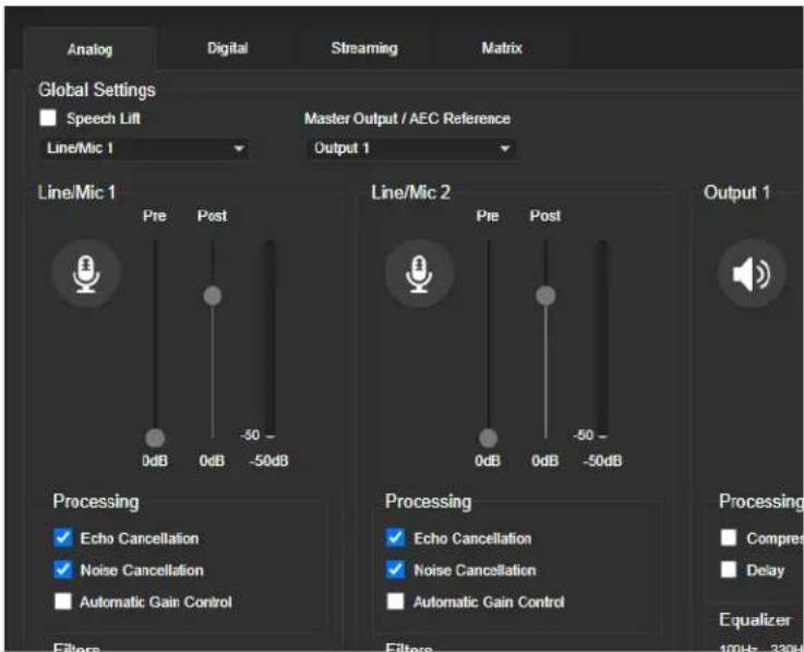
Speech Lift: Feeds the signal from the specified microphone to the speakers in the room, so that people in the back of the room can hear the person who is speaking.
Chairman Override: Gives priority to the specified microphone when more than one person is speaking. (Matrix tab only)
Microphone Adjustments
AUDIO PAGE, ANALOG TAB
To adjust for more natural speech reproduction:
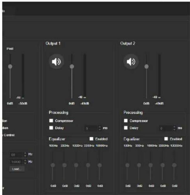
- High-pass filter – Specify the lowest frequency that the microphone should pick up. Use this setting to reduce low-frequency background noise such as heating/air conditioning systems.
- Low-pass filter – Specify the highest frequency that the microphone should pick up. Use this setting to reduce hissing sounds and make speech sound natural.
- PEQ (parametric equalizer) – Increase or reduce the volume of specific frequency ranges to compensate for the audio challenges unique to the situation.
Note
As a best practice, use the equalizer to attenuate undesirable frequency ranges rather than to be desirable frequencies.

Speaker Adjustments
AUDIO PAGE, ANALOG AND STREAMING TABS
To sync the sound with the video:
If the video lags noticeably behind the audio, check the Delay box for the appropriate audio out (Analog or Streaming tab) and enter a delay value in msec. The delay may differ from one ou another.
To compensate for differing speech volumes:
If some people on the far end are inaudible while others are too loud, check the Compressor I reduce the dynamic range from the connected speakers. (Analog tab only.)
To compensate for specific audio issues on the far end:
Use the equalizers for the analog outputs to attenuate specific frequency ranges. This can help if end audio includes unwanted elements such as a rumbling HVAC system or a cricket in the roc
About Echo Cancellation
When a microphone picks up the audio from a speaker (far-end audio) during a conference, it is far-end audio back to the participants at the far end, creating an echo. Acoustic echo cancellation prevents this.
Here's how it works:
-
The speaker feeds the far-end audio into the room. This signal also goes to the audio proc the reference that needs to be canceled.
-
The audio processor inverts the signal and sends it to the microphone.
-
The sum of the audio that the microphone picks up from the speaker and the inverted signal echo is canceled.
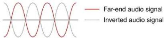
With the audio from the speaker canceled out, the audio from the microphone includes only the originating at your end of the conference.
Preventing Audio Feedback
AUDIO PAGE, ANALOG TAB
Audio feedback results when the microphones pick up audio from the speakers.
- Select Echo Cancellation on any line inputs that are connected to signal sources.
- In the Global Settings, under Master Output/AEC Reference, select the audio output to use as reference - the signal that will be cancelled out of the inputs. Set Master Output/AEC Referen Output 2 if using Line Out 2 for the speaker connection, as shown in some of the connecti in this manual.

System Maintenance
This chapter covers the tasks on the System page:
■ Exporting (backing up) and importing configuration data
■ Updating firmware
■ Rebooting
It also includes information that you may need if you contact Vaddio Technical Support.
Some of the screen shots in this chapter are from other OneLINK products, and may differ some from the web interface that you see.
Exporting and Importing Configuration Data
SYSTEM PAGE, FIRMWARE TAB
You can export a device's configuration and save it as a backup. This allows you to quickly re customized information if you need to restore factory defaults or replace the unit, or import a configuration to multiple devices.
The exported data includes settings that may be the same on several devices – the room label, time zone information, audio settings, and streaming settings.
Security and network settings are not included in the export file.
When importing a configuration to multiple devices:
■ All the devices must be of the same model.
■ All the devices must have compatible firmware versions installed.
To export a configuration:
To save a copy of the current configuration, select Export Data.
The configuration exports as a .dat file and downloads to your default file download location. The filename is the device's hostname followed by the .dat file extension.

To import a configuration:
- Select Import. The Import Data box opens.
- Select Choose File, and browse to the .dat file to be imported.
- Select Begin Importing Data. When the import is complete, the device reboots.
Starting a Firmware Update
SYSTEM PAGE
Caution
Do not remove power or disconnect the OneLINK device while a firmware update in progress. Interrupting a firmware update can make the OneLINK device unusable.
- Be sure you have downloaded the appropriate update file to your computer.
- OPTIONAL: Select Export Data to save a copy of the OneLINK device's current configuration. probably won't need it, but it could save time if you need to roll back the update.
- Select Choose File, browse to the firmware update file that you downloaded, and select it. The filename ends with .p7m. The System page then displays the filename beside the Choose File button.
- Select Begin Firmware Update.

- READ the information in the Confirm dialog box and be sure you understand it.
- When you are ready to start the update, select Continue.
- If you have any problems with the update, take screen shots if possible, and contact Vaddio support. We can help you better when we have the exact text of any warnings or error me you encounter. See Contacting Vaddio Technical Support and Viewing Diagnostics.
Rebooting the OneLINK Device
SYSTEM PAGE
This may help if the OneLINK device stops responding as you expect. In the System Utilities section of the System page, select Reboot.
Contacting Vaddio Technical Support and Viewing Diagnostics
HELP PAGE, DIAGNOSTICS PAGE
If you encounter an issue that you can't resolve using your superior troubleshooting skills (and the Troubleshooting section of this guide), go to the Help page for information on contacting Vaddio Technical Support.
Note
The web interface provides links to the company's standard privacy policy because the device's IF address is considered "personally identifiable information". This product does not record or save audio video files, and it does not store any identifying information other than what you may choose to the Room Labels page of the web interface.
Your Vaddio technical support representative may ask you to download and email the event log 1 available from the Diagnostics page. The log may include large numbers of internal events even errors have occurred. Rebooting generates over 100 log entries.

Serial Command API
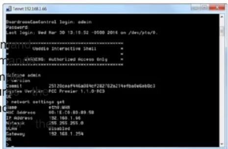
The Vaddio serial command API is a high-level, text-based command line interface to allow an e: device such as AMX or Crestron to control the OneLINK device. The serial command API can be accessed via Telnet. Windows provides a built-in Telnet client; PuTTY can also be used.
Telnet connections use port 23.
Note
At the start of the session, you must log in using the admin account.
Note
By default, Telnet access is disabled in all firmware releases issued after December 2019. Enable the Security page of the web interface.
Usage notes:
■ The > character is the command prompt.
- Using a question mark as a command or command parameter will bring up a list of available commands, or command parameters. For example, returns all top-level commands; system return valid subcommands for the system command; and system reboot? returns the parameter available system reboot command.
■ CTRL-5 clears the current serial buffer on the device.
Typographical conventions:
■ {x | y | z} - Choose x, y, or z.
-
■ < x - y > - Valid range of values is from x through y.
■ [parameter] - Parameter is not required.
Note
The commands in this manual refer to the OneLINK device. To control the connected camera, of Telnet session to the camera's IP address and use the camera's Telnet commands, or connect a controller to the OneLINK device's RS-232 port and use the camera's VISCA-compatible RS-232 se control API.
Audio Management Commands
The following commands are available for audio management:
■ audio volume
■ audio mute
■ audio route
■ audio crosspoint-gain
Channels Available for Audio Commands
Audio mute and volume commands may be applied to all audio channels at once (master) or specific input or output. Routing and crosspoint gain commands must specify individual channels.
Inputs
| master All audio | inputs(Not available for audio route and audio crosspoint-gain commands) |
| line_in_1 and line_in_2 | Microphones or other line-level inputs |
| usb3_playback_left and usb3_playback_right | Left and right USB audio channels from the far end |
| hdbt_in_left and hdbt_in_right | Left and right audio channels from a connected HDBaseT input device |
Outputs
| master All audio | outputs |
| line_out_1 and line_out_2 | Speakers or other line-level outputs |
| usb3_record_left and usb3_record_right | Left and right USB audio channels from your site |
| hdmi_out_left and hdmi_out_right | Left and right audio channels out to a connected HDMI device |
| hdbt_out_left and hdbt_out_right | Left and right audio channels out to a connected HDBaseT device |
audio volume
Gets or sets the volume of the specified audio channel.
See Channels Available for Audio Commands for the audio input and output channels available.
| Synopsis audio | ||
| Options | get | Returns the current volume of the specified channel. |
| up | Increases the volume of the specified channel. | |
| down | Reduces the volume of the specified channel. | |
| set | Sets the volume of the specified channel. | |
| Examples | audio line_in_1 volume set -5OK>Sets -5 dB as the volume for the device connected to the Line In 1 port.audio line_out_1 volume getvolume -10.0 dBOK>Returns the current volume for the speaker connected to the line out port. | |
audio mute
Gets or sets the mute status of the specified audio channel.
See Channels Available for Audio Commands for the audio input and output channels available.
| Synopsis audio | ||
| Options | get | Returns the current mute status of the specified channel. |
| on | Mutes the audio for the specified channel. | |
| off | Unmutes the audio for the specified channel. | |
| toggle | Changes the mute state for the specified channel - unmutes if it was muted, mutes if it was not. | |
| Examples | >audio line_out_1 mute getmute: offOK>Returns the current mute state of the device connected to audio line out 1. Mute off, so the audio is on.>audio master mute onOK>Mutes all audio. | |
audio route
Gets or sets the input routed to the specified output.
See Channels Available for Audio Commands for the audio input and output channels available.
| Synopsis audio | ||
| Options get Returns the routing for the specified output. | ||
| setSets the routing for the specified input. More than one input may be specified. | ||
| Examples | >audio line_out_1 route get[usb3_playback_left usb3_playback_right]OK>Returns the current source of the audio output on Line Out 1 (typically a speal Both channels of far-end audio from the USB stream are currently routed to this output. | |
audio crosspoint-gain
Returns or sets the current routing gain, in dB, for the crosspoint between a given output and See Channels Available for Audio Commands for the audio input and output channels available.
| Synopsis audio | ||
| Options | get | Returns the gain from the specified input to the specified output. |
| set<-12.0 .. 12.0> Sets the | gain from the specified input to the specified output. Valid range is -12.0 dB. | |
| Examples | >audio line_out_1 crosspoint-gain usb3_in_left get 3.9OK>Returns the gain from the left channel of the USB 3 playback to the Line Out output.>audio line_out_1 crosspoint-gain usb3_in_left set -3OK>Sets the gain from the left channel of the USB 3 playback to the Line Out 1-3 dB. | |
Communication and Power Commands
These commands are available for managing power and sequences of actions:
■ network settings get
■ link power
network settings get
Returns the current network settings for MAC address, IP address, subnet mask, and gateway.
| Synopsis network | settings get |
| Example | > network settings getName eth0:WANMAC Address 00:1E:C0:F6:CA:7BIP Address 192.168.1.67Netmask 255.255.255.0VLAN DisabledGateway 192.168.1.254OK> |
link power
Sets the camera's power connection on or off.
Note
The OneLINK device does not provide camera control. To set the camera to standby instead of it off, use the camera's remote or other camera control interface to issue a standby command of the camera.
| Synopsis link power {on | off} | ||
| Options | off | Powers off the camera connection. Camera power remains off until the OneLINK device receives a link power on command or a reboot. |
| on | Powers on the camera connection. | |
| Examples | >link power offOK>Powers off the camera connection. | |
Maintenance and Troubleshooting Commands
The following commands are available for maintenance and troubleshooting:
■ version
■ network ping
■ system reboot
■ system factory-reset
version
Returns the current firmware version of the OneLINK device.
| Synopsis version | |
| Example | versionReturns current firmware version information in a form something like this: |
network ping
Sends an ICMP ECHO_REQUEST to the specified IP address or hostname.
| Synopsis network ping [count] [size] | |
| OptionsThe number of ECHO_REQUEST packets to send. Default is five packets. | |
| Examples>network ping 192.168.1.66PING 192.168.1.66 (192.168.1.66): 56 data bytes64 bytes from 192.168.1.66: seq=0 ttl=64 time=0.476 ms64 bytes from 192.168.1.66: seq=1 ttl=64 time=0.416 ms64 bytes from 192.168.1.66: seq=2 ttl=64 time=0.410 ms64 bytes from 192.168.1.66: seq=3 ttl=64 time=0.410 ms64 bytes from 192.168.1.66: seq=4 ttl=64 time=3.112 ms--- 192.168.1.66 ping statistics ---5 packets transmitted, 5 packets received, 0% packet loss round-trip min/avg/max = 0.410/0.964/3.112 ms>Sends five ECHO_REQUEST packets of 56 bytes each to the host at 192.168.1.66 | |
| >network ping count 10 size 100 192.168.1.1Sends 10 ECHO_REQUEST packets of 100 bytes each to the host at 192.168.1.1The command returns data in the same form as above. | |
system reboot
Reboots the system either immediately or after the specified delay. Note that a reboot is required resetting the system to factory defaults (system factory-reset).
| Synopsis system | reboot [] | |
| OptionsThe number of seconds to delay the reboot. | ||
| Examples Reboots the system immediately.>system reboot 30Reboots the system in 30 seconds. The response appears at the | ||
end of the c
system factory-reset
Gets or sets the factory reset status. When the factory reset status is on, the OneLINK device factory defaults on the next reboot.
Note
This does not reset the camera.
| Synopsis system | factory-reset {get | on | off} | |
| Options | get | Returns the camera's current factory re status. |
| on | Enables factory reset on reboot. | |
| off | Disables factory reset on reboot. | |
| Examples | >system factory-reset getfactory-reset (software): offfactory-reset (hardware): offOK>Returns the factory reset status.This evaluates the most recent system factory-reset on or off command, if one has been received, then reads the rear panel DIP switches status on if they are all in the down position.>system factory-reset onfactory-reset (software): onfactory-reset (hardware): offOK>Enables factory reset upon reboot.NoteThis command does not initiate a factory reset. The factory reset the next reboot. | |
and returns the
takes place o
Telnet Information and Session Management Commands
The following commands are available for Telnet help and session management:
■ help
■ history
exit
You can also use a question mark as a command or command parameter to display a list of commands, subcommands, or command parameters. For example, ? returns all top-level commands; system ? returns the valid subcommands for the system command; and system reboot ? returns any parameters available for the system reboot command.
history
Returns the most recently issued commands from the current session.
| Synopsis history | ||
| Options | nteger value specifying the maximum number of commands to return. | |
| Examples | historyDisplays the current command buffer.history 5Sets the history command buffer to remember the last 5 unique entries. | |
Additional information | You can navigate the command history using the up and down arrow keys.This command supports the expansion functionality from which previous commands can be recalled from within a single session. History expansion is performed immediately after a complete line is read.Examples of history expansion:* !! Substitute the last command line.* !4 Substitute the 4th command line (absolute as per 'history' command)* !-3 Substitute the command line entered 3 lines before (relative) | |
help
Displays an overview of the CLI syntax.
| Synopsis help | |
Example | help |
exit
Ends the command session and closes the socket.
| Synopsis | exit |
| Example | exit |
Troubleshooting
When the equipment doesn't behave as you expect, check for error indications and messages first Check the camera:
If the problem might be with the Vaddio camera connected to the OneLINK device, check the c camera's status light before you do anything else – but keep in mind that the camera's status turned off in the administrative interface.
- Purple – booting or in standby (low power) mode.
■ Blue – normal operation. - Red – Tally function; the camera is on-air.
■ Blinking blue – video is muted. - Blinking red – video is muted, or fault condition.
■ Yellow – firmware update in progress.
Check the OneLINK device:
Now check the OneLINK device's web interface for error messages.
If neither of these reveal the problem, use these tables to determine whether it's time to call V Technical Support.
Power Issues
| What is it doing? Possible causes Check and correct | ||
Nothing.The lights are off.camera is not recepower. | The OneLINK device's power pack. The plugged in to main power.ving | #Nugs the power pack into a wall outlet. |
| The wall outlet is not active. (Check they OneLINK power pack finding out if it powers something different, outlet.such as a laptop or phone charger.) | ||
| "He's dead, Jim." Contact your | reseller or Vaddio Technical Support. | |
| The camera is not receiving power but OneLINK device has power. | The camera cable is bad. Replace the cable. | |
| Camera does not find booting or does not to the ready state. | Possible cable issue. Test with go | shorter cables.Try re-terminating the cable. |
Communication Issues
| What is it doing? Possible causes Check and correct | ||
| The camera is on, its web interface is available. | Abutable is not connected. Make not | sure all network and OneLINK cables are connected. |
| The network or OneLINK cable | is bad. Replace the bad cable. | |
| The camera is not using the address you browsed to. | IP'addio cameras: Press the Data Screen button on the remote to camera's IP address. | |
see the
Video and Audio Issues
| What is it doing? Possible causes Check and correct | ||
| The camera is on not transmitting video. | Possible cable length issue. Try o. | a better grade of cable (Cat-6 or Cat-7) for the OneLINK connection. |
| Video drops out repeatedly. | Possible cable inductance issue. | Do not store excess cable by neatly.Best practice: Build cables to the required length. |
| Video and audio do match up - speech audible before the person on the far appears to start speaking. | The audio signal is arriving before video signal, which is normal but desirable.end | For the affected audio outputs (Line OutnotHDMI Out, or USB Record), enable Delay and enter a value in milliseconds. |
| When connected to conferencing codec: Far-end audio drops out periodically, and the issue may intensify. | Echo cancellation is enabled on the codec and the OneLINK device. | Disable echo cancellation on the OneLINK device. |
| Audio feedback or echo that intensifies. | Echo cancellation is disabled. If | using the OneLINK device with a conferencing codec, enable echo cancellation on the codec. Otherwise, enable echo cancellation on the OneLINK device. |
Restoring Factory Defaults
This operation returns the device to its original state.
■ Any settings you have customized will be lost.
■ Anyone who is logged in to the web interface is logged out.
- You will need to do the initial device setup again to be able to communicate with the device. You can restore factory defaults from the web interface (System page, Firmware tab) or by sending Telnet command system factory-reset on followed by system reboot. If you are not able to log in to the device, contact Vaddio Technical Support.
If the password is unknown:
-
Disconnect power.
-
Press and hold the IP address button while reconnecting power; continue to hold the button 1 seconds.
Operation, Storage, and Care
For smears or smudges on the product, wipe with a clean, soft cloth. Use a lens cleaner on not use any abrasive chemicals.
Keep this device away from food and liquids.
Do not operate or store the device under any of the following conditions:
■ Temperatures above 104°F (40°F) or below 32°F (0°C)
■ High humidity, condensing or wet environments
■ Inclement weather
■ Severe vibration
■ In or on top of a pizza oven
■ Dry environments with an excess of static discharge
Do not attempt to take this product apart. There are no user-serviceable components inside.
Index
A
acoustic echo cancellation 24
adjusting microphones 24
admin login 15
admin password 14
initial 14
AEC 27
AGC (automatic gain control) 24-25
ambient noise, suppressing 24
anatomy of the OneLINK device 2
API 31-32, 35-36, 38
syntax help 38
audio 21, 23-27, 32-34
controls 21, 24-26
crosspoint gain 34
delay 25-26
feedback, preventing 24, 27
matrix, default 23
matrix, editing 23, 34
muting 21, 33
routing 23
volume 21, 33
Audio page (web) 21-27
automatic gain control 24
automatic inactivity time-out (web session) 15
automatic NTP updating 18
B
backing up a configuration 28
browser compatibility 11
C
cable connectors 2-3
cables 1, 3, 10
maximum length 1, 3
null-modem 10
capabilities 1
chairman override (microphone setting) 24
cleaning 41
command history 38
commands 32
compatibility, browsers 11
configuration data 28
exporting 28
importing 28
configuration, saving or restoring 28
configuring 27
AEC reference 27
connection diagram 5-10
block, HDBaseT camera 5
block, HDBaseT camera with codec 6
Vaddio HDBaseT with Cisco C20 7
Vaddio HDBaseT with Cisco C40 8
Vaddio HDBaseT with Cisco C60 8
Vaddio HDBaseT with Cisco SX20 9
Vaddio HDBaseT with Cisco SX80 10
Vaddio HDBaseT with Polycom RPG 310 6
Vaddio HDBaseT with Polycom RPG 500 6
Vaddio HDBaseT with Polycom RPG 700 7
connectors 2-3
identification 2
cycle power to the camera 35
D
damage, preventing 3
date and time 18
default settings, restoring 37, 41
DHCP addressing 17
DHCP vs. non-DHCP networks 13
Diagnostics page (web) 30
dynamic range 25
E
echo cancellation 24-25, 27
equalizer 25-26
equipment location information 18
exporting configuration data 28
F
factory defaults, restoring 37, 41
fault isolation 39
firmware update 29
firmware version 36
G
getting help 30
graphic equalizer 26
H
Help page (web) 30
HID audio controls 20
high-pass filter adjustment (microphones) 25
hostname 17
|
importing a configuration 28
inactive sessions (web interface) 15
indicator lights 39
information, equipment location 18
initial device set-up 12-14
using the Vaddio Device Controller 12
using Vaddio Deployment Tool 13
installation 4
mounting 4
IP address 13, 16-17
changing to static 17
configuring 16-17
conflicts, preventing 16
default 13, 16-17
L
locations of connectors 2
low-pass filter adjustment (microphones) 25
M
mic boost 25
microphones 21-22, 24, 32-33
acoustic echo cancellation 24
adjusting volume 21
automatic gain control 24
chairman override 24
default settings 24
filter adjustments 25
muting 21, 33
noise cancellation 24
PEQ (parametric equalizer) 25
powering 22
speech lift adjustment 24
muting audio 21, 33
microphones 21
speakers 21
N
network configuration 16-17
default 17
network configuration information (Telnet) 35
Networking page (web) 16-18
noise cancellation 24-25
NTP server 18
0
operating environment 41
P
page 15-18, 20-30
Audio 21-27
Diagnostics 30
Help 30
Networking 16-18
Room Labels 18
Security 15
Streaming 20
System 28-29
password 14
passwords 15
changing 15
PEQ (parametric equalizer) 25
phantom power 22
ping command 36
power on/power off 10, 35
camera 35
powering microphones 22
problems, solving 39
product capabilities 1
R
rebooting 29, 37
restoring a configuration 28
restoring default settings 37, 41
RJ-45 connectors, recommendation 3
room information, adding 18
Room Labels page (web) 18
routing audio 23, 34
RS-232 32, 35-36, 38
RS-232 adapter for Cisco products 10
S
saving a configuration 28
Security page (web) 15
serial command API 32, 35-36, 38
settings, default, restoring 37
software update 29
solving problems 39
speakers 21, 26, 32-33
adjusting for differing speech volumes 26
adjusting volume 21
equalizer 26
muting 21, 33
synchronizing audio with video 26
speech lift (microphone setting) 24
static IP address 16-17
storage environment 41
storing a configuration 28
Streaming page (web) 20
streaming settings 20
supported web browsers 11
synchronizing audio with video 26
System page (web) 28-29
system time 18
Room Labels page 18
Security page 15
Streaming page 20
System page 28-29
T
tablet 12
technical support 30
Telnet command help 38
Telnet commands 32, 35-36, 38
Telnet session 31, 38
ending 38
history 38
temperature, operating and storage 41
third-party control 32, 35-36, 38
time zone 18
troubleshooting 39
typographical conventions for command reference 31
U
updating firmware 29
USB device name 20
USB Record volume 21
USB streaming 20
V
Vaddio Deployment Tool 12-13
check for the latest version 12
initial device set-up 13
Vaddio Device Controller 12
version, firmware 36
volume controls 21, 33
W
web browsers supported 11
web interface 12, 15-18, 20-30
accessing 12
Audio page 21-27
Diagnostics page 30
Help page 30
Networking page 16-18
Vaddio is a brand of Legrand AV Inc. · www.legrandav.com · Phone 800.572.2011 / +1.763.971.4400 ·
Fax +1.763.971.4464 · Email av.vaddio.support@legrand.com
Vaddio is a registered trademark of Legrand AV Inc. All other brand names or marks are used identification purposes and are trademarks of their respective owners. All patents are protected under existing designations. Other patents pending.
©2022 Legrand AV Inc.
- OneLINK Bridge Express
- Contents
- Overview ...1
- Overview
- What's in this Guide
- Features
- A Quick Look at the OneLINK Device
- Connector Panel of the Receiver
- Installing the OneLINK Device
- Don't Void Your Warranty!
- Caution
- Note
- Cabling Notes
- Intact
- Damaged
- Pro Tip
- RS-232 Connector Pin-Out
- Mounting the OneLINK Device
- About Installations Using Half-Recessed Ceiling Mounts
- Connections for HDBaseT Cameras
- Connections for HDBaseT Cameras Used with Codecs
- Connecting a Vaddio HDBaseT Camera and Polycom Codec
- RoboSHOT HDBT Camera and Polycom RealPresence Group 310 Codec
- RoboSHOT HDBT Camera and Cisco C20 Codec
- RoboSHOT HDBT Camera and Cisco C60 Codec
- RoboSHOT HDBT Camera and Cisco SX20 Codec
- RoboSHOT HDBT Camera and Cisco SX80 Codec
- Hardware Note: RS-232 Connections
- Hardware Note: Connections and Configuration Changes
- OneLINK Device Configuration for Audio Using a Codec
- Powering Up the Equipment
- Web Interface
- Working with the Connected Camera
- Compatible Web Browsers
- Initial Device Set-Up and System Administration Tasks
- Initial Device Set-Up Using the Vaddio Device Controller
- Initial Device Set-Up Using the Vaddio Deployment Tool
- Accessing the Web Interface Manually
- To get the IP address:
- To access the web interface:
- If the Device Is At 169.254.10.1
- To communicate directly with the device:
- Completing the Initial Device Set-up
- System Administration
- Configuring Access and Other Security Settings
- SECURITY PAGE
- Configuring a Static IP Address for a Device Currently at 169.254.10.1
- NETWORKING PAGE
- To access the device's Networking page after initial device setup:
- Changing from an Automatically Assigned Address to a Static IP Address
- Changing the Device's Hostname
- Specifying Time Zone and NTP Server
- Adding Room Information to the Web Interface
- ROOM LABELS PAGE
- Serial Control Settings
- Accessing the Connected Camera's Web Interface
- Performance and Behavior Settings
- Configuring USB Streaming Settings
- STREAMING PAGE
- Configuring Audio Settings
- AUDIO PAGE
- Quick Adjustments – Muting and Volume
- AUDIO PAGE, ANALOG, DIGITAL, AND STREAMING TABS
- To mute all microphones:
- To control volume on individual inputs or outputs:
- Enabling Phantom Power to Microphones
- Reading the Audio Matrix
- AUDIO PAGE, MATRIX TAB
- Routing Audio
- Default Microphone Settings
- Microphone Settings for Environments with Audiences
- Microphone Adjustments
- Speaker Adjustments
- About Echo Cancellation
- Preventing Audio Feedback
- System Maintenance
- Exporting and Importing Configuration Data
- To export a configuration:
- To import a configuration:
- Starting a Firmware Update
- SYSTEM PAGE
- Rebooting the OneLINK Device
- Contacting Vaddio Technical Support and Viewing Diagnostics
- Serial Command API
- Usage notes:
- Typographical conventions:
- Audio Management Commands
- Channels Available for Audio Commands
- audio volume
- audio mute
- audio route
- audio crosspoint-gain
- Communication and Power Commands
- link power
- Maintenance and Troubleshooting Commands
- version
- network ping
- system reboot
- system factory-reset
- Telnet Information and Session Management Commands
- history
- help
- exit
- Troubleshooting
- Check the OneLINK device:
- Restoring Factory Defaults
- If the password is unknown:
- Operation, Storage, and Care
- Index
- A
- B
- C
- D
- E
- F
- G
- H
- |
- L
- M
- N
- 0
- P
- R
- S
- T
- U
- V
- W
Brand : Vaddio
Model : OneLINK Bridge Express
Category : Audio/video converter