
Fire Jet - Pump ASTRALPOOL - Free user manual and instructions
Find the device manual for free Fire Jet ASTRALPOOL in PDF.


| Type of product | Fountain unit with isopropanol flame effect (Fire Jet) |
| Dimensions (diameter x height) | Ø250 mm x 553 mm |
| Power supply | 230 V AC, 500 W, 2.7 A |
| Maximum operating pressure | 16 bar (recommended 10–16 bar) |
| Maximum isopropanol consumption | 0.2 l/s |
| Maximum flame height | 4–10 m |
| Protection rating | IP68 |
| Minimum safety distance | 10 m from people |
| Water temperature range | 4 °C to 35 °C |
| Water quality requirements | pH 6.9–7.8, free chlorine 0.5–2.0 ppm, TDS < 2000 ppm |
| Duty cycle | 20% maximum (e.g., 2 sec activation per 10 sec) |
| Maximum activation time (isopropanol outlet) | 1 sec |
| Maximum activation time (electric arc) | 2 sec |
| Minimum interval between activations | 20 sec |
| Maximum water evacuation capacity | 100 l/min |
| Wearing parts (not covered by warranty) | Electrovalves |
| Installation | Outdoor only, must be fixed to ground with M8 anchor bolts |
| Country of origin | Spain |
Frequently Asked Questions - Fire Jet ASTRALPOOL
User questions about Fire Jet ASTRALPOOL
0 question about this device. Answer the ones you know or ask your own.
Ask a new question about this device
Download the instructions for your Pump in PDF format for free! Find your manual Fire Jet - ASTRALPOOL and take your electronic device back in hand. On this page are published all the documents necessary for the use of your device. Fire Jet by ASTRALPOOL.
USER MANUAL Fire Jet ASTRALPOOL
natural_image
3D rendering of a cylindrical industrial device with mounting legs and wiring (no text or symbols visible)Made
in
SPAIN
CE

EQUIPOS PARA FUENTES FOUNTAIN UNITS
Fire Jet


Fig. 1
Fig. 2
INSTALLATION, OPERATION AND MAINTENANCE MANUAL
Fire Jet
TABLE OF CONTENTSTABLE OF CONTENTS
1 GENERAL SAFETY 15
1.1 ELECTRICAL SAFETY 15
1.2 SAFETY IN USE AND CONTACT WITH WATER 16
1.3 OPERATION AND MAINTENANCE SAFETY 16
2 INSTALLATION AND ASSEMBLY 17
2.1 FASTENING AND LEVELLING THE UNIT 17
2.2 WIRING 18
1.1 ELECTRICAL SAFETY
- Disconnect the unit from the power supply before doing any assembly or maintenance jobs.
- Do not touch the water or get into the water while the unit is connected to the power supply.
- Use an H07RN-F type waterproof cable.
- Connect the unit to an earth connection. Make use of one of the unit's fastening points (see chapter 2.1).
- It is mandatory to install a security system in the electrical panel to monitor the electric arc activation by current. Only in this case the isopropanol solenoid valves can be activated. As it is a safety system, the non-installation, deactivation or lack of maintenance exempts the manufacturer from liability for damage to persons, installations and equipment operation.
- It is mandatory to install an emergency stop system that cut the power supply to the equipment, in case of risks derived from equipment malfunction.
- Connect the unit to a power supply with an earth connection, protected by the following components:
- An RCD safety switch with a maximum residual current of 30 mA.
- A circuit breaker fuse properly sized according to the power consumption of the unit.
1.2 SAFETY IN USE AND CONTACT WITH WATER
- The water in the fountain where the unit is to be fitted must meet the following conditions:
| Characteristics of the water | Minimum value | Maximum value |
| Temperature 4 °C | 35 °C | |
| pH 6.9 7.8 | ||
| Free residual chlorine | 0.5 ppm 2.0 ppm | |
| Total alkalinity (TAC) | 80 ppm 120 ppm | |
| Calcium hardness (CH) | 200 ppm 1,000 ppm | |
| Salt level - 2 g/l | ||
| Total dissolved solids (TDS) | - 2,000 ppm | |
- If the temperature is below 4^ C, empty the unit to prevent it from breaking due to the formation of ice inside it.
- Do not tamper with the factory-fitted waterproof seals. Otherwise, the unit could lose its warranty.
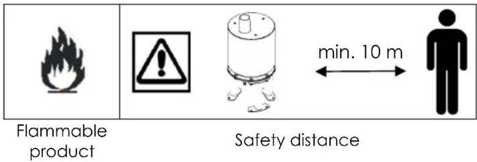
WARNING: Risk of burns. The unit gives off a flame fed by isopropanol, a highly flammable liquid.
- Do not install the equipment in accessible areas to people.
- Equipment for outdoor installation, not recommended for indoor installation neither pedestrian areas. Any different installation of the recommended conditions exempts the manufacturer from liability for damage to persons or installations.
- Set a minimum security distance of 10 m between the installation perimeter where the equipment is located and people access.
- Put up signs around the fountain in line with the country's or local regulations. Examples of warnings: "Bathing is prohibited", "Water unsafe to drink", "Danger of electric
Fountain units
[en]
shock".
Note: In addition to the standard warnings on fountains, put up a “Danger of burns” sign.
- Do not open or handle any of the unit's components other than those for which explanations are given in this manual. Other handling makes losing device's warranty.
- Do not handle wiring with damp or wet hands.
- Do not handle the unit if it is connected to the main power supply.
- The unit may only be handled by authorised personnel or qualified service engineers. Do not allow unauthorised personnel or unqualified service engineers to handle it.
2 INSTALLATION AND ASSEMBLY
IMPORTANT:
- Read the whole manual carefully before installing the unit.
- Check that it is in a good state of repair on removing the packaging.
- Identify all components prior to their installation.
- Avoiding warnings on this user's guide can lead to improper handling and breakage of the unit, so the product will lose its warranty.
2.1 FASTENING AND LEVELLING THE UNIT
WARNING: Risk of damage to the unit and losing its warranty. Install the equipment ensuring that the fountain maximum level does not exceed the maximum level marked on the equipment body. Ensure the fountain maximum level with overflow, as otherwise the maximum level can not be guaranteed. In case of equipment flooding for not respecting the maximum level, the equipment will lose its warranty.
Components required for fastening the unit:
| Component Number | |
| Anchor bolt: M8 A4 AISI 316 threaded rod and capsule | 6 |
| DIN 9021 D.8 A4 flat washer 6 | |
| DIN 934 M8 A4 nut 12 |
WARNING: Risk of damage to the unit. Install device's anchoring following this instructions:
7) Fasten the anchor bolts (22)b) to the ground.
8) Level the unit and fasten on each anchoring point using 2 nuts on each in order to prevent from undesired movements
9) Periodically check the fixing to ensure the equipment vertical position, to avoid the risks derived from bad equipment orientation.
2.2 WIRING
2.2.1 Fuel
WARNING: Risk of damage to the unit and losing its warranty. Clean all piping prior to connecting and starting the unit up.
WARNING: Risk of damage to the unit and losing its warranty. The fuel impulsion system (isopropanol) made by compressed air, is not included on the device. It is highly recommendable to install air regulators and accumulators, necessaries for the correct use of the device. It is also recommended the installation of an air-drying system to remove any water in the unit. All this components must be sized and installed following the current applicable regulations in the country of installation.
WARNING: Risk of damage to the unit and losing its warranty. Before the equipment commissioning, carry out tightness testing of the isopropanol impulsion system from the tank to the equipment. The manufacturer DOES NOT HAVE ANY RESPONSIBILITY in the combustible fluid distribution and impulsion installation, but it is recommended to pay special attention at this point, and
Fountain units
collaborate with engineering and authorized installers of compressed air and flammable liquids.
WARNING: Risk of damage to the unit and losing its warranty. In order for the safe and proper operation of the unit, the following components are required (not included with the device):
1) A compressed air unit for discharging the isopropanol.
2) An isopropanol storage tank PN16 minimum, sized in order to contain enough isopropanol for the fountain show needs.
3) A non-return valve placed between the air compressor and the isopropanol tank.
4) A manifold on the isopropanol tank exit if there is more than one device working simultaneously.
5) Conduits for the compressed air and the isopropanol suitable for working under water and for the working pressure, minimum PN16. Also pipes must be inert in contact with isopropanol.
6) Isopropanol pipe must be water-tight. Before the equipment commissioning, carry out pipe water-tightness testing.
Connect tank's isopropanol outlet to the conduit at the bottom (④, ¼" Whitworth male thread).
It is highly recommended installation of isopropanol cutting valve before device inlet in order to do maintenance tasks.
Maximum device working pressure is 10Kg/cm^2 .
2.2.22 Electrical
WARNING: Risk of damage to the unit and losing its warranty. Check that all IP68 connectors are properly sealed and that they prevent water getting through. Electrical components may become damaged by flooding and the unit could lose its warranty.
WARNING: Risk of damage to the unit and losing its warranty. Connect a fuse on the current transformer positive and on the electrovalve (230VAC) in order to protect the device from overcurrents.
- 5A fuse on current transformer positive (grey wire).
- 2A fuse on electrovalve positive (brown wire).
[en] Fountain units
Connect electrical wiring (⑤) to the control panel: (See fig.2)
a) Current transformer power supply for generating electric arc (Ignition) at 230VAC (Grey and black wires).
b) Electrovalves power supply for generating isopropanol nebulization shoot (Injection) at 230VAC (Blue and brown wires).
c) Current transformer and electrovalves earth connection (Green/yellow wire).
WARNING: Risk of serious burns. Protect the flame outlet from the wind and do not operate in strong wind. If the unit is installed in an area frequently exposed to strong wind, it is possible that the wind will displace the spray of fuel and it will be discharged without igniting.
3.1 OPERATION
The operation of the unit will depend on the control system installed, which is not supplied with this unit.
WARNING: Before starting normal device operation, isopropanol inlet pipes must be feeded through various electrovalve activations until isopropanol nebulization is correct.
WARNING: Risk of damage to the unit and losing its warranty. Maximum working pressure must be 16 bar.
Recommended working pressure is 10 - 16 bar. In case of working out of this range, the flame effect could not be proper.
WARNING: Risk of damage to the unit and losing its warranty. Activation frequency must be over 20 sec.
Maximum duty cycle of the equipment is 20%. Do not activate device more than 2 secs every 10 secs in the choreographies.
WARNING: Risk of damage to the unit and losing its warranty. Maximum activation time must be 1 sec on the isopropanol outlet and 2 secs for the electric arc.
Activate electric arc 0,5 secs before activating isopropanol outlet, to ensure ignition of the combustible fluid is the correct operation way.
Never exceed these activation times.
Fountain units
[en]
WARNING: Risk of damage to the unit and losing its warranty. The equipment maximum water evacuation capacity is 100l/min. Never exceed this water input flow in the equipment. In case of equipment flooding for not respecting the maximum water evacuation, the equipment will lose its warranty.
In order to avoid device flooding, do not direct water jets at the equipment; neither install it near jets that can introduce water inside the equipment.
WARNING: Risk of damage to the unit and losing its warranty. Never activate the equipment when it is being splashed by a water jet, or when there is water inside the equipment. In case of contact with water inside the equipment, wait a minimum of 30 secs until the next activation.
3.2 MAINTENANCE
DANGER: Risk of death from electric shock. Disconnect the unit from the mains power supply before doing any maintenance work on the unit.
WARNING: Risk of damage to the unit. Any adjustments made to the electrodes that involves handling them must be carried out by a qualified service engineer.
Regularly check that the electrodes are clean: remains of soot build up on the electrodes during operation. It is advisable to use a damp cloth to clean them taking great care not to move the electrodes from their position.
Periodically check the activation system of the Fire Jets to guarantee the proper activation.
3.3 WORN PARTS
Electrovalves are worn parts fo the device and are not included on the product warranty.
4 TECHNICAL SPECIFICATIONS
| Input voltage 230 V AC | |
| Total power load 500 W | |
| Rated current 2.7 A. | |
| Maximum pressure 16 bar | |
| Jet nozzle height 4–10 m | |
| Isopropanol consumption 0,2 l/s |
5 FAQs
Question Answer
Why isn't the isopropanol discharged from the nozzle?
If you have an anemometer sensor, the wind speed may be faster than the default set-point.
Wait until the wind speed in the area has dropped.
Check that the control panel's electrical outlet is on.
Check the status of the circuit breaker.
Why doesn't the isopropanol discharged from the nozzle ignite?
Check the position of the electrodes. The electric arc between the electrodes may not be forming.
Check that the control panel's electrical outlet is on.
In other cases or if the answers have not resolved the problem detected, contact a service engineer (see the list of approved engineers on the product's warranty).
6 PRODUCT LABELLING
IF |  |  |  |  |
| IP68 protection rating | Not operational T < 4 °C | Safe management of waste electrical and electronic equipment Directive 2002/96/EC (WEEE) | The unit's documentation must be read before use | Danger of electric shocks |
7 WARRANTY
See attached document "Warranty certificate for fountain units".
8 ENVIRONMENT
At the end of its working life, every wasted component must be correctly managed according to the current environmental regulations of the country in which it is installed.


Code 66567E202/Rev. 00
Made in
Spain
VAT NO.: ES
A08246274
Nos reservamos el derecho de cambiar total o parcialmente
[es] las características de nuestros artículos o el contenido de este documento sin previo aviso.
Wir behalten uns das Recht vor die Eigenschaften unserer
[de] Produkte oder den Inhalt dieses Prospektes teilweise oder vollständig, ohne vorherige Benachrichtigung zu ändern.
[en] We reserve the right to change all or part of the features of the articles or contents of this document without prior notice.
Nous réservons le droit de modifier totalement ou en partie les
[fr] caractéristiques de nos articles ou le contenu de ce document sans préavis.
Ci riserviamo il diritto di cambiare totalmente o parzialmente
[it] le caratteristiche tecniche dei nostri prodotti o il contenuto di questo documento senza nessun preavviso.
Reservamo-nos no diereito de alterar, total ou parcialmente
[pt] as características dos nossos atigos ou o conteúdo deste documento sem aviso prévio.
- INSTALLATION, OPERATION AND MAINTENANCE MANUAL
- Fire Jet
- TABLE OF CONTENTSTABLE OF CONTENTS
- GENERAL SAFETY 15
- INSTALLATION AND ASSEMBLY 17
- ELECTRICAL SAFETY
- SAFETY IN USE AND CONTACT WITH WATER
- Fountain units
- INSTALLATION AND ASSEMBLY
- IMPORTANT:
- FASTENING AND LEVELLING THE UNIT
- WIRING
- Fuel
- Electrical
- [en] Fountain units
- OPERATION
- MAINTENANCE
- WORN PARTS
- TECHNICAL SPECIFICATIONS
- FAQs
- Question Answer
- PRODUCT LABELLING
- WARRANTY
- ENVIRONMENT
Brand : ASTRALPOOL
Model : Fire Jet
Category : Pump