
STST1825 - Saw STANLEY - Free user manual and instructions
Find the device manual for free STST1825 STANLEY in PDF.


| Type | Table Saw |
| Brand | STANLEY |
| Model | STST1825 |
| Power Source | AC, 120V/60Hz or 220V/50Hz/60Hz (depending on region), 15A |
| No Load Speed | 4800 RPM |
| Blade Diameter | 10" (254mm) |
| Table Size | 24" x 20" (610mm x 508mm) |
| Max Cutting Depth at 90° | 3" (76mm) |
| Max Cutting Depth at 45° | 2.2" (56mm) |
| Blade Bevel Range | 0° to 45° |
| Weight | 30.55 kg |
| Safety Features | Blade guard, splitter, anti-kickback pawls, safety switch with key, double insulation |
| Key Components | Rip fence, miter gauge, push stick, blade elevation handle, blade tilting wheel, leg stand, extension table |
| Maintenance | Keep clean, check cord, replace damaged parts, no lubrication required |
| Spare Parts / Accessories | Replacement blades, blade wrenches, rip fence, miter gauge, push stick; use genuine STANLEY parts |
| Repairability | Repairs by authorized service centers only; user-replaceable items: blade, splitter, anti-kickback pawls |
| Environmental | Do not dispose with household waste; separate collection for recycling |
| Certifications | Double insulated; complies with relevant standards |
Frequently Asked Questions - STST1825 STANLEY
User questions about STST1825 STANLEY
0 question about this device. Answer the ones you know or ask your own.
Ask a new question about this device
Download the instructions for your Saw in PDF format for free! Find your manual STST1825 - STANLEY and take your electronic device back in hand. On this page are published all the documents necessary for the use of your device. STST1825 by STANLEY.
USER MANUAL STST1825 STANLEY
natural_image
Line drawing of a Stanley wood machine with visible components and frame structure (no text or symbols)Español 3
Português 11
English 18
MANUAL DE INSTRUÇÕES
INSTRUCTION MANUAL
WARNING: READ INSTRUCTION MANUAL BEFORE USING PRODUCT.

--- ..... Corriente Directa

natural_image
Two sets of mechanical fasteners: a black bolt and three white washers (no text or symbols)
natural_image
Close-up of two metallic hardware components with circular features, labeled B2 (no text or symbols on the components themselves)
natural_image
Close-up of a black metal bracket with two holes and mounting holes (no text or symbols visible)Paso 3
natural_image
Close-up of a hand holding a black rectangular object with a small protrusion, labeled B6 (no text or symbols on the object itself)natural_image
Close-up of a mechanical component with visible teeth and internal structure (no text or symbols)natural_image
Close-up of hands assembling a mechanical component with arrows indicating assembly direction (no text or symbols)Nivel

natural_image
Close-up of hands assembling a mechanical component (no visible text or symbols)Instalar la guarda de la hoja (FIG. G1 y G2)
natural_image
Close-up of a hand using a transparent plastic tool to cut a circular saw (no visible text or symbols)natural_image
Interior view of a lab or workshop setup with mechanical arms and a tiled wall (no visible text or symbols)
natural_image
Close-up of a person using a mechanical tool on a mechanical component, labeled H2 (no visible text or symbols)natural_image
Black-and-white photo of a person interacting with a white appliance and a black panel, no visible text or symbols on the main subject.natural_image
Close-up of hands operating a mechanical component, labeled H4 in the corner (no other text or symbols visible)natural_image
Close-up of a hand holding a black circular object with a white tip, next to a computer monitor (no visible text or symbols)natural_image
Close-up of a hand pressing a button on a metal surface, with arrows indicating motion direction (no text or symbols visible)natural_image
Silhouette of a mechanical component with a pointed tip, possibly a tool or bracket (no visible text or symbols)
Ajuste del tope paralelo
natural_image
Close-up of a hand pressing down on a mechanical component, possibly part of a device or panel (no visible text or symbols)
natural_image
Close-up of a mechanical device with a tool inserted, labeled 'K2' in the corner (no other text or symbols visible)OPERACIÓN
natural_image
Close-up of a hand holding a small object with an arrow pointing to it, next to a black button (no visible text or symbols)natural_image
Close-up of a hand pressing a small component on a textured surface, with no visible text or symbols.natural_image
Close-up of a hand operating a cleaning machine with a circular component, no visible text or symbolsnatural_image
Close-up of a hand holding a mechanical component with a 255mm scale indicator (no readable text or symbols)Detener cuello
El divisor
natural_image
Close-up of a mechanical assembly or circuit board with no visible text or symbolsnatural_image
Mechanical assembly with a vertical rod and mounting base, no visible text or symbolsnatural_image
Close-up of a mechanical assembly with a white cylindrical component and plastic wrap, no visible text or symbolsnatural_image
Close-up of a mechanical assembly with a metal bracket and a curved component, no visible text or symbolsnatural_image
Black-and-white photo of a mechanical device with exposed internal components, no visible text or symbolsnatural_image
Close-up of a mechanical assembly with transparent frame and internal components (no visible text or symbols)Tuerca
APLICACIONES
Puntas de corte
Monte as pernas da base
1. Identificar as partes e acessórios
2. Monte as pernas da base
Paso 1
natural_image
Close-up of a black metal bracket with two circular screws, labeled B2 (no text or symbols on the main subject)
natural_image
Close-up of a black metal bracket with mounting holes and a circular hole, labeled B3 (no text or symbols on the structure itself)Paso 3
natural_image
Close-up of a hand holding a black plastic object with a label 'B6' (no other text or symbols visible)Adaptar a serra de bancada no suporte (consulte a FIG. C1, C2)
natural_image
Close-up of a mechanical component with visible gears and internal structure (no text or symbols)natural_image
Close-up of hands assembling or adjusting a mechanical component with arrows indicating features (no visible text or symbols)Nível

natural_image
Close-up of hands assembling or adjusting a mechanical component, no visible text or symbolsnatural_image
Person using a metal cutting tool on a workbench, wearing a transparent plastic cage (no visible text or symbols)natural_image
Person operating a mechanical testing setup with support bars and a transparent frame (no visible text or symbols)
natural_image
Close-up of hands assembling or adjusting a mechanical component, labeled H2 in the corner (no visible text or symbols on the main subject)natural_image
Person interacting with a device labeled H3, showing wiring and components (no readable text or symbols)natural_image
Close-up of hands assembling a mechanical component (no visible text or symbols)natural_image
Close-up of a hand holding a black circular object, next to a device labeled '255mm Bench' (no readable text on object)Montar a guia paralela
natural_image
Silhouette of a mechanical component with a pointed tip, possibly a tool or bracket (no visible text or symbols)
natural_image
Close-up of two hands operating a mechanical device with a clamp, labeled J2 J3 (no visible text or symbols on the device itself)natural_image
Close-up of a hand pressing down on a metal panel, labeled K1 in the corner (no other text or symbols visible)
natural_image
Close-up of a computer interface with a mouse and a tool, labeled K2 (no readable text or symbols on the device itself)natural_image
Close-up of a hand pressing a small object on a textured surface, with no visible text or symbols.natural_image
Close-up of a hand operating a 15.5mm Baffle 3.5mm switch device (no visible text or symbols on the device itself)natural_image
Close-up of a hand holding a mechanical component with a 255mm scale indicator (no readable text or symbols)Anel de parada
A lâmina separadora
natural_image
Close-up of a mechanical component with visible alignment and mounting features (no text or symbols)Graminho (consulte a Fig. R, S)
natural_image
Mechanical assembly with a vertical rod and mounting bracket, no visible text or symbolsnatural_image
Close-up of a mechanical component with a tool interacting with it, showing internal turbulence and a circular feature (no text or symbols visible)natural_image
Close-up of a mechanical assembly with a hand operating a sheet metal (no visible text or symbols)Corte angular composto (Consulte a Fig. X)
natural_image
Close-up of a mechanical assembly with a cylindrical component and a flanged base, no visible text or symbolsnatural_image
Black-and-white photo of a hand holding an open electronic device with visible circuit board (no readable text or symbols)DO NOT RETURN THIS PRODUCT TO THE STORE, first contact your local STANLEY Office or nearest authorized service center.
GENERAL SAFETY RULES
⚠ Warning! Read and understand all instructions. Failure to follow all instructions listed below, may result in electric shock, fire and/or serious personal injury.
SAVE THESE INSTRUCTIONS

SAFETY INSTRUCTIONS General power tool safety warnings. Warning! Read all safety warnings and
all instructions. Failure to follow the warnings and instructions listed below may result in electric shock, fire and/or serious injury.
Save all warnings and instructions for future reference.
The term "power tool" in all of the warnings listed below refers to your mains operated (corded) power tool or battery operated (cordless) power tool.
1. Work Area Safety
a. Keep work area clean and well lit. Cluttered and dark areas invite accidents.
b. Do not operate power tools in explosive atmospheres, such as in the presence of flammable liquids, gases or dust. Power tools create sparks which may ignite the dust or fumes.
c. Keep children and bystanders away while operating a power tool. Distractions can cause you to lose control.
2. Electrical Safety
a. Power tool plugs must match the outlet. Never modify the plug in any way. Do not use any adapter plugs with earthed (grounded) power tools. Unmodified plugs and matching outlets will reduce risk of electric shock.
b. Avoid body contact with earthed or grounded surfaces such as pipes, radiators, ranges and refrigerators. There is an increased risk of electric shock if your body is earthed or grounded.
c. Do not expose power tools to rain or wet conditions.
Water entering a power tool will increase the risk of electric shock.
d. Do not abuse the cord. Never use the cord for carrying, pulling or unplugging the power tool. Keep cord away from heat, oil, sharp edges or moving parts. Damaged or entangled cords increase the risk of electric shock.
e. When operating a power tool outdoors, use an extension cord suitable for outdoor use. Use of
a cord suitable for outdoor use reduces the risk of electric shock.
f. If operating a power tool in a damp location is unavoidable, use a residual current device (RCD) protected supply. Use of an RCD reduces the risk of electric shock. Note: The term "Residual Curent Device (RCD)" can be replaced by "Ground Fault Circuit Interrupter (GFCI)" or by "Earth Leakage Circuit Breaker (ELCB)".
3. Personal Safety
a. Stay alert, watch what you are doing and use common sense when operating a power tool. Do not use a power tool while you are tired or under the influence of drugs, alcohol or medication. A moment of inattention while operating power tools may result in serious personal injury.
b. Use personal protective equipment. Always wear eye protection. Protective equipment such as dust mask, non-skid safety shoes, hard hat, or hearing protection used for appropriate conditions will reduce personal injuries.
c. Prevent unintentional starting. Ensure the switch is in the off-position before connecting to power source and/or battery pack, picking up or carrying the tool. Carrying power tools with your finger on the switch or energising power tools that have the switch on invites accidents.
d. Remove any adjusting key or wrench before turning the power tool on. A wrench or a key left attached to a rotating part of the power tool may result in personal injury.
e. Do not overreach. Keep proper footing and balance at all times. This enables better control of the power tool in unexpected situations.
f. Dress properly. Do not wear loose clothing or jewellery. Keep your hair, clothing and gloves away from moving parts. Loose clothes, jewellery or long hair can be caught in moving parts.
g. If devices are provided for the connection of dust extraction and collection facilities, ensure these are connected and properly used. Use of these devices can reduce dust related hazards.
4. Power Tool Use and Care
a. Do not force the power tool. Use the correct power tool for your application. The correct power tool will do the job better and safer at the rate for which it was designed.
b. Do not use the power tool if the switch does not turn it on and off. Any power tool that cannot be controlled with the switch is dangerous and must be repaired.
c. Disconnect the plug from the power source and/or the battery pack from the power tool before making any adjustments, changing accessories, or storing
power tools. Such preventive safety measures reduce the risk of starting the power tool accidentally.
d. Store idle power tools out of the reach of children and do not allow persons unfamiliar with the power tool or these instructions to operate the power
tool. Power tools are dangerous in the hands of untrained users.
e. Maintain power tools. Check for misalignment or binding of moving parts, breakage of parts and any other condition that may affect the power tools operation. If damaged, have the power tool repaired before use. Many accidents are caused by poorly maintained power tools.
f. Keep cutting tools sharp and clean. Properly maintained cutting tools with sharp cutting edges are less likely to bind and are easier to control.
5. Service
a. Have your power tool serviced by a qualified repair person using only identical replacement
parts. This will ensure that the safety of the power tool is maintained.
6. Electrical safety

Your tool is double insulated; therefore no earth wire is required. Always check that the main voltage corresponds to the voltage on the rating plate.

Warning! If the power cord is damaged, it must be replaced by the manufacturer, authorized STANLEY Service Center or an equally qualified person in order to avoid damage or injury. If the power cord is replaced by an equally qualified person, but not authorized by STANLEY, the warranty will not be valid.
7. Labels on tool
The label on your tool may include the following symbols:

Read Instructions Manual
Hz ..... Hertz W ..... Watts
☐ ..... Class II Construction ● .... Earthing Terminal

Use Eye Protection
min ..... minutes \~ ..... Alternating Current

Earthing Terminal

Use Ear Protection
\~ .... Alternating Current

Safety Alert Symbol
- .... Direct Current
.../min.. Revolutions or Reciprocation per minute
V ......
Volts Amperes
n_0 ..... No-Load Speed
A ......
FEATURES (FIG. A)
- Rip Fence
- Blade Guard
- Splitter
- Anti-kickback Pawls
- Miter Gauge
-
Table
-
On/Off Switch
- Leg Stand
- Blade Elevation Handle
- Blade Tilting Wheel
- Saw Blade
- Spanner Wrench
- Push Stick
ADDITIONAL SAFETY RULES FOR TABLE SAWS
⚠ Warning! Failure to follow these rules may result in serious injury.
- DO NOT OPERATE THIS MACHINE until it is assembled and installed according to the instructions.
- OBTAIN ADVICE FROM another qualified person if you are not familiar with the operation of this machine.
- FOLLOW ALL WIRING CODES and recommended electrical connections.
- USE THE GUARDS WHENEVER POSSIBLE.
Check to see that they are in place, secured, and working correctly.
- KICKBACK IS THE NATURAL TENDENCY OF THE WORKPIECE TO BE THROWN BACK AT THE
OPERATOR when the workpiece initially contacts the
blade or if the workpiece pinches the blade. Kickback is dangerous and can result in serious injury.
AVOID KICKBACK by:
a. keeping blade sharp and free of rust and pitch.
b. keeping rip fence parallel to the saw blade.
c. using saw blade guard and spreader for every possible operation, including all through sawing.
d. pushing the workpiece past the saw blade prior to release.
e. never ripping a workpiece that is twisted or warped, or does not have a straight edge to guide along the fence.
f. using featherboards when the anti-kickback device cannot be used.
g. never sawing a large workpiece that cannot be controlled.
h. never using the fence as a guide when crosscutting.
i. never sawing a workpiece with loose knots or other flaws.
6. ALWAYS USE GUARDS, SPLITTER, AND ANTI-KICKBACK FINGERS whenever possible.
7. REMOVE CUT-OFF PIECES AND SCRAPS from the table before starting the saw. The vibration of the machine may cause them to move into the saw blade and be thrown out. After cutting, turn the machine off. After the blade has come to a complete stop, remove all debris.
8. NEVER START THE MACHINE with the workpiece against the blade.
- NEVER run the workpiece between the fence and a moulding cutterhead.
- CUTTING THE WORKPIECE WITHOUT THE USE OF A FENCE OR MITER GAUGE IS KNOWN AS "FREEHAND" CUTTING. NEVER perform "free-hand" operations. Use either the fence or miter gauge to position and guide the workpiece.
- HOLD THE WORKPIECE FIRMLY against the miter gauge or fence.
- CUTTING COMPLETELY THROUGH THE WORKPIECE IS KNOWN AS "THROUGH-SAWING".
Ripping and cross-cutting are through-sawing operations. Cutting with the grain (or down the length of the workpiece) is ripping. Cutting across the grain (or across the workpiece) is cross-cutting. Use a fence or fence system for ripping. DO NOT use a fence or fence system for cross-cutting. Instead, use a miter gauge. USE PUSH STICK(S) for ripping a narrow workpiece.
- AVOID AWKWARD OPERATIONS AND HAND POSITIONS where a sudden slip could cause a hand to move into the blade.
- KEEP ARMS, HANDS, AND FINGERS away from the blade.
- NEVER have any part of your body in line with the path of the saw blade.
- NEVER REACH AROUND or over the saw blade.
- NEVER attempt to free a stalled saw blade without first turning the machine "OFF".
- PROPERLY SUPPORT LONG OR WIDE workpieces.
- NEVER PERFORM LAYOUT, assembly or set-up work on the table/work area when the machine is running.
- TURN THE MACHINE "OFF" AND DISCONNECT THE MACHINE from the power source before installing or removing accessories, before adjusting or changing set-ups, or when making repairs.
- TURN THE MACHINE "OFF", disconnect the machine from the power source, and clean the table/work area before leaving the machine. TURN THE SWITCH IN THE "OFF" POSITION.
POWER CONNECTIONS
Before connecting the machine to the power line, make sure the switch (s) is in the "OFF" position and be sure that the electric current is of the same characteristics as indicated on the machine. All line connections should make good contact. Running on low voltage will damage the machine.
⚠ Danger! Do not expose the machine to rain or operate the machine in damp locations.
Before connecting the machine to the power source, make sure the switch is in the "OFF" position.
ASSEMBLY
Assembly of the leg stand
When assembling the stand, it is recommended that the screws are only lightly tightened until the stand is fully assembled.
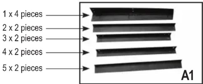
1. Identify the parts and fittings
Before you start the assembly of the stand's legs, fully unpack the saw and lay out the individual parts.
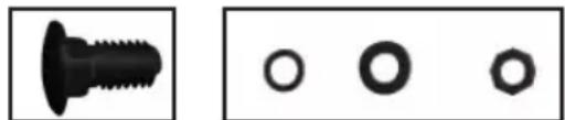
Clearly identify the parts shown in Fig. A1 and A2, including the fittings. Group these parts together and ensure that you have the correct quantity of all the pieces shown.
Bolt Washer
natural_image
Two sets of mechanical fasteners: a black bolt and three white washers (no text or symbols)
2. Assemble the stand's legs
Step 1
Select the following parts:
2 x Part 1
1 x Part 3
1 x Part 5
Lay the parts together as shown in Fig. B1, B2, and
B3. This is best done by simply laying the parts loosely together on the floor. Once you are satisfied that you have the parts correctly laid together, start the fitting process.
Align the holes and secure with the bolts (a) as shown
in Fig. B1.
DO NOT fully tighten the bolts, nuts and washers at this point. Finger tight is sufficient.
Step 2
Repeat Step 1 so that there are two frames assembled.


natural_image
Close-up of two black electronic components with metallic pins, labeled B2 (no text or symbols on the components themselves)
natural_image
Close-up of a black metal bracket with bolt holes and a circular hole, labeled B3 (no text or symbols on the structure itself)Step 3
Select the following parts:
2 x Part 2
2 x Part 4
These will form the crosspieces between the previously assembled frames. Lay the parts flat on the floor. Connect the longer Part (2) and fix it to the frame in the center of the uprights. Note that Part
2 should be positioned as shown in Fig. B4. Connect Part 4 (top cross support) to the top of the frame. Note that Part 4 should be positioned as shown in Fig. B4.

Step 4
Now place and connect the ends of the top and center frame supports to the frame. Take care to ensure that the supports are positioned as shown in Fig. B5.

Step 5
Once you are satisfied that the frame is assembled correctly, fully tighten ALL the bolts.
Finally, assemble the 4 foot pads to the bottom of each leg (see Fig. B6).

natural_image
Close-up of a hand holding a black plastic object with a label 'B6' in the corner (no other text or symbols visible)Fitting the table saw to the stand (see FIG. C1, C2)
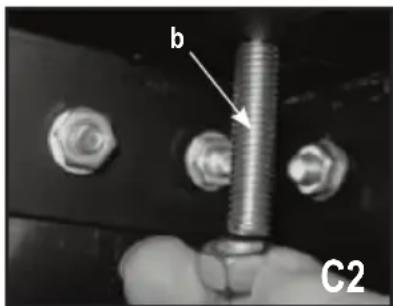
There are four mounting holes on the base of the saw. 4 corresponding mounting holes are located on the top plane of the stand. Put the table saw on the stand, match the holes on the base of the saw with the holes on the stand, and secure them with the 4 bolts (b) provided. DO fully fasten.

natural_image
Close-up of a hand holding a threaded bolt with two bolts, labeled 'b' and 'C2' (no other text or symbols visible)Adjusting the splitter (FIG. D1-D3)
The splitter (3) has two positions: storage position (Fig. D1) and working position (Fig. D2). The splitter is in the storage position when you take it out of the package.

natural_image
Close-up of a mechanical component with gear-like structure and labeled D1 (no readable text or symbols)Slots Working Position Holes
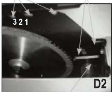
Locking Level
To place the splitter in the working position:
a. Remove the blade throat plate.
b. Raise the blade up to the highest position by turning the blade control wheel counterclockwise. Set the bevel at 0°. Make sure the bevel is locked tight.
c. Release the splitter locking lever by pulling the lever up.
d. Pull the splitter up to the working position. The two working position holes should align with the two pins on the fixture.
e. Lock the splitter by pushing the splitter locking lever down.
Note: Make sure the splitter is locked securely.
f. Place the blade throat plate back on.
To adjust the splitter to be in the storage position:
Repeat steps a to c described above and slide the splitter down to the storage position. Lock the splitter locking lever. Lower the blade to the lowest position. The splitter should be under the saw table.
To adjust the height of the splitter (Fig. D3)
Loosen the two nuts (c). Adjust the two adjusting nuts (d) to make sure the splitter is approximately 1/8" (3 mm) above the blade tips. Tighten the two nuts (c).

To adjust the alignment of the splitter
The splitter must be precisely IN LINE with the saw blade. Loosen the two nuts (c) and align the splitter with the saw blade. Once aligned, hold the splitter. To prevent personal Injury, always unplug the saw from power source before making any adjustments.
Installing the anti-kickback pawls (FIG. F1 and F2) NOTE: The Splitter (3) needs to be in working position to install the anti-kickback pawl assembly.
- Raise the blade to the highest position and set bevel at 0°. Make sure the bevel is locked tight.
- Place the anti-kickback pawl assembly over the "keyhole" Slot (1) (Fig. D2) on the Splitter (3). Depress the plastic cap on the lock pin in the direction shown on Fig. F1. Rotate the lever downwards, and make sure the lock pin fully engages the slot (1).
- Release the plastic cap to secure assembly. Make sure there is no movement in the anti-kickback pawl assembly.
To uninstall the anti-kickback pawl assembly, depress the plastic cap on the lock pin to release it. Rotate the lever downwards, pull and remove the assembly from the splitter.
Plastic cap

natural_image
Close-up of hands assembling a mechanical component with arrows indicating assembly direction (no text or symbols)Lever

natural_image
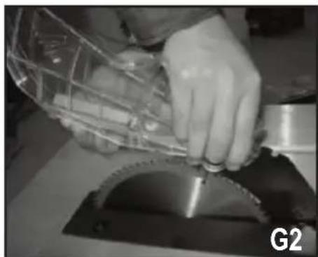
Close-up of hands assembling a mechanical component (no visible text or symbols)Installing the blade guard (FIG. G1 and G2)
-
Position the blade guard assembly over the "L" shaped slot (2) on the splitter so that the pin (1) engages the slot a (2) completely. See Fig. G1.
-
Place the blade guard assembly down on the splitter. Depress the lock button.
- Slide the blade guard assembly backwards and push it downwards with a little force so that the lock pin engages fully into the slot (3).
- Release the lock button to secure. See Fig. G2

natural_image
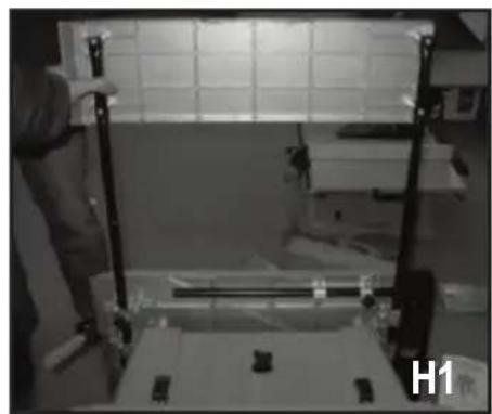
Close-up of hands operating a metal cutting machine with a transparent cage (no visible text or symbols)Installing the extension table and extension rail Insert the extension pieces into the holes of the table (See Fig. H1) and screw down the knob. (See Fig. H2)
natural_image
Interior view of a laboratory or lab setup with equipment and a person standing near a table (no visible text or symbols)
natural_image
Close-up of a person adjusting mechanical components with a tool (no visible text or symbols)Insert the extension rails into the holes of the table (See Fig. H3)

natural_image
Black-and-white photo of a person standing beside a white appliance with visible internal components and wires, labeled H3 in the corner (no readable text or symbols on main subject)Assemble the handle (see FIG. H4)
Put the handle on the extension table and tighten it with supplied screws.

natural_image
Close-up of hands operating a mechanical component, no visible text or symbolsAssembly of the table saw
Elevating and lowering handle
- Mount the blade elevation handle (9) on the wheel by tightening the nut in the handle. (See Fig. I)

natural_image
Close-up of a hand pressing a button on a surface, with a computer monitor and keyboard visible in the background (no readable text or symbols)Mounting the rip fence
- Mount the locking handle onto the front of the rip fence (1) by tightening the nut in the handle. (See Fig. J1)
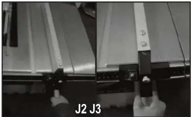
- If needed, release the locking handle by pulling it upward. Mount the rip fence onto the saw so that the side with the indicator is on the scale side of the saw (See Fig. J2). Start by sliding the front of the rip fence onto the front side of the table so that the front locking plate contacts the front side of the table then push down on the back of the rip fence so that the fence is level on the table. Be sure both locking plates are in contact with both the front and back edges of the table. (See Fig. J3)

natural_image
Close-up of a hand holding a tool near a computer interface (no visible text or symbols)OPERATION
On/off Safety Switch
Warning! Before turning on the On/Off switch, make sure the blade guard is correctly installed and operating properly. To start the machine, open the safety key and press the switch to the "ON" position. (See Fig. L)
natural_image
Close-up of a mechanical component with metal parts and a hand holding a tool, labeled 'J2 J3' at the bottom (no other text or symbols visible)Rear locking plate

natural_image
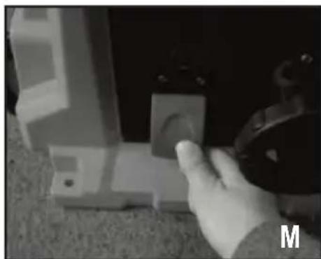
Close-up of a hand holding a small white object with an arrow pointing to it, next to a dark mechanical component (no visible text or symbols)When turning the switch "ON", stand to either side of the blade and never directly in front of it. Allow blade to reach full speed before cutting. To stop the machine, press the switch in the "OFF" position (See Fig. M), or open the safety key to lock the ON/OFF switch in the "OFF" position.
natural_image
Close-up of a hand pressing a small component on a textured surface, with no visible text or symbols.Blade elevation handle
The blade elevation handle is used to raise and lower the saw blade. Turn clockwise to lower the blade and counterclockwise to raise it. (See Fig. N).
Adjustment of the rip fence
- The rip fence has been adjusted at the factory to be at a 90^ angle to the front side of the table. If it is not at a 90^ angle to the table, loosen the two bolts at the top front side of the rip fence and adjust the rip fence angle so it is at 90^ . (See Fig. K1)
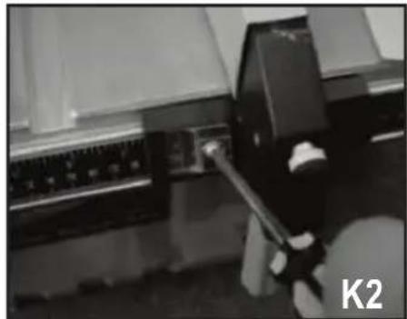
- Move the rip fence to contact the side of the blade (the zero point) and then check that the rip fence position indicator is on the "0" mark on the scale. If it is not, loosen the screw and position the indicator on "0" and then retighten the screw. (See Fig. K2)
Note: The blade guard and splitter will need to be removed to perform this adjustment.

natural_image
Close-up of a hand using a tool to press or install a metal panel, no visible text or symbols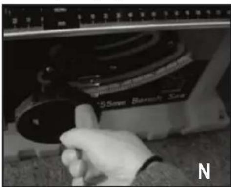
natural_image
Close-up of a hand operating a computer mouse with a black dial and a ruler above (no visible text or symbols)
natural_image
Close-up of a hand operating a computer mouse with a black dial and a ruler above (no visible text or symbols)Blade tilting wheel
The blade tilting wheel (10) is used to tilt the saw blade for bevel cutting. (See Fig. O).

The stop collar holds the bevelling mechanism in the desired position. (See Fig. P).
When setting the angle of the cut, loosen the stop collar by turning it counter-clockwise. Rotate the blade tilting wheel and use the bevel scale. Set the blade at the desired angle. Tighten the stop collar by turning it clockwise.
Before turning the table saw "ON", be sure all adjustments are securely tightened to prevent the blade from shifting during operation.

natural_image
Close-up of a hand holding a small mechanical component, with no visible text or symbols on the device itself.Stop collar
The splitter
The Splitter (3) separates the two pieces of wood that result after the work-piece is pushed through the saw blade. The splitter prevents binding and kickback.
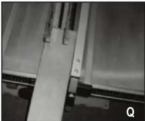
Rip fence (see Fig. Q)
This rip fence is used for all ripping operations. Never rip freehand without the fence in place and securely locked.
natural_image
Close-up of a mechanical assembly with metal components and a labeled part 'Q' (no readable text or symbols)Miter gauge (see Fig. R, S)
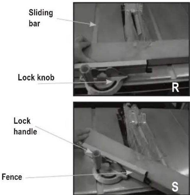
The miter gauge (5) is used for performing cross cuts and miter cuts. The gauge head is locked in the desired position by tightening the lock knob. Always ensure the lock knob is securely fastened before starting a cut. To adjust the miter gauge angle, loosen miter gauge lock handle and rotate the miter gauge body so that the "0" mark on the end of the sliding bar points to desired position. Then tighten the lock handle.
Note: The miter gauge body has marks at 5-degree increments. The sliding bar has marks at 1-degree increments. Read both to get an accurate angle degree. To adjust the miter gauge fence, loosen the lock knob and slide the fence to the desired position. Then tighten the lock knob.
Push stick (see Fig. T)
Device used to feed the work-piece through the saw during narrow ripping cuts. The push stick (13) helps to keep the operator's hands well away from the blade. Use the push stick for ripping widths less than 6" (150 mm) and more than 2" (50 mm).

natural_image
Mechanical assembly with metal components and a labeled part 'T' (no readable text or symbols)Changing the saw blade
Always unplug the saw from the power source before maintenance to avoid risk of serious personal injury.
To remove the blade:
- Remove the blade guard and the blade throat plate (See Fig. U).
- Raise the blade to the highest possible position.
- To keep the arbor from rotating, place one of the spanners on the flange flats.
- Place the second spanner on the arbor nut.
- Turn the second spanner clockwise to tighten, counterclockwise to loosen. Loosen and remove the arbor nut. (See Fig. V).
- Remove the flange and pull the blade off the motor shaft.
- To install the blade, reverse the procedure.


natural_image
Close-up of a hand using a tool to brush through a dark, glossy liquid onto a rectangular surface (no text or symbols visible)▲ Important! Blade rotation is clockwise when observing from the right side of the saw. Make sure the rotation direction mark on blade matches with that.
BASIC TABLE SAW OPERATIONS
a. When crosscutting, miter cutting, bevel cutting, compound miter cutting or rabbeting across the end of a narrow work-piece, use the miter gauge.
b. Never make these cuts freehand (not using the miter gauge or other devices) because the blade could bind, causing a kickback or causing your hand or fingers to contact the blade.
c. Always lock the angle of the miter gauge when in use.
d. Except for when making rip cuts, remove the rip fence from the table (6).
e. Make sure the blade guard is mounted for all through sawing operations (the blade cuts through the entire thickness of the wood). Re-attach the guard immediately after finishing dado, molding or rabbeting cuts.
f. The blade should extend approximately 1/8" (3 mm) above the top of the work-piece.
g. Use the push stick whenever you make a narrow cut.
Crosscutting (see Fig. R)
Crosscutting is cutting wood across the grain at 90^ or square with both the edge and the flat side of the wood. This is done with the miter gauge set at "0". Before using the miter gauge, make sure it is locked. The miter gauge can be used in either of the grooves in the table.
Miter crosscutting (See Fig. S)
Miter crosscutting is cutting the wood at an angle other than 90^ . Follow the same procedures as you would for crosscutting. Adjust the miter gauge to the desired angle.
Bevel crosscutting (See Fig. W)
Bevel crosscutting is the same as crosscutting except that the blade is also set at an angle other than 90^ . Adjust the blade to the desired angle using the blade tilting wheel.

natural_image
Close-up of a hand using a tool to cut or spread material on a machine (no visible text or symbols)Compound miter cutting (See Fig. X)
Compound miter cutting is a combination of miter cutting and bevel crosscutting. The cut is made at an angle other than 90^ to both the edge and the flat side of the wood. Adjust the miter gauge and the blade bevel to the desired angle and be sure that the miter gauge and blade bevel stop collar are locked.

natural_image
Close-up of a mechanical assembly with pipes and a tool, no visible text or symbolsRipping (See Fig. Q)
Ripping is cutting a piece of wood with the grain. This is done using the Rip Fence. Position the fence to the desired width of the rip cut and lock it in place. Before starting to rip, make sure:
a. The rip fence is parallel to the saw blade. b. The splitter is properly aligned with the saw blade. When ripping long boards or large panels, always use a work-piece support. Hold the material to be cut against the rip fence and feed it through the blade with smooth, steady pressure.
Only apply feed pressure to the work-piece between the blade and the rip fence in order to prevent the work-piece from binding against the blade and causing kickback. When ripping boards narrower than 6" (150 mm), use a push stick to feed the work-piece until it is clear of the table.
Bevel ripping (See Fig. T)
When bevel ripping material 6" (150 mm) or narrower, use the rip fence on the right side of the blade only.
Transportation (See Fig. Y)
Use the right side extension, in the extended position, as a temporary handle to transport the table saw on its wheels.

natural_image
Black-and-white photo of a mechanical device with visible internal components and no readable text or symbolsSawdust collection (See Fig. Z)
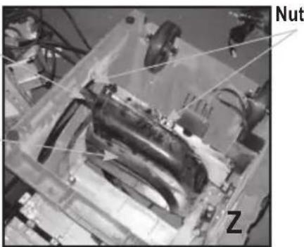
This table saw is equipped with a removable sawdust collector. A dust collection system can be attached to the dust port to help remove sawdust from the work area. To remove the sawdust collector, simply loosen two nuts and remove the collector from the saw.
Dust port
Sawdust collector
natural_image
Close-up of a mechanical assembly with labeled parts (Nut and Z), no readable text or symbols beyond labelsAPPLICATIONS
Cutting Tips
- Make sure the kerf is made on the scrap side of the measuring line.
- Cut the wood with the finished side up.
- Always have a proper support for the wood as it comes out of the blade.
- Make a test cut for important cuts.
-
Always use the correct blade depth setting. The top of the blade teeth should clear the top of the material being cut by 1/8" (3 mm) to 1/4" (6 mm).
-
Inspect the work-piece for knots or nails before beginning a cut. Remove any loose knots with a hammer.
- Always use clean, sharp, properly-set blades. Never make a cut with a dull blade.
- When making a cut, use steady, even pressure. Never force a cut.
- DO NOT cut wet or warped lumber.
- Always hold your work-piece firmly with both hands or use a push stick or push block.
MAINTAIN TOOLS WITH CARE
Remove the plug from the socket before carrying out any adjustment, servicing or maintenance.
Keep tools sharp and clean for better and safer performance. Inspect tool cords periodically and if damaged, have repaired by an authorized service facility. Your power tool requires no additional lubrication or maintenance. There are no user serviceable parts in your power tool. Never use water or chemical cleaners to clean your power tool. Wipe clean with a dry cloth. Always store your power tool in a dry place. Keep the motor ventilation slots clean. Keep all working controls free of dust. If you see some sparks flashing in the ventilation slots, this is normal and will not damage your power tool.
If the supply cord is damaged, it must be replaced by the manufacturer, its service agent or similarly qualified persons in order to avoid a hazard.
▲ Important! To assure product SAFETY and RELIABILITY, repairs, maintenance and adjustment (other than those listed in this manual) should be performed by authorized service centers or other qualified service personnel, always using identical replacement parts.
ACCESSORIES
2 Blade wrenches, 1 rip fence, 1 miter gauge and 1 push stick
We recommend that you purchase your accessories from the same store that sold you the tool. Use good quality accessories marked with a well- known brand name. Choose the type according to the work you intend to undertake. Refer to the accessory packaging for further details. Store personnel can assist you and offer advice.
PROTECTING THE ENVIRONMENT

Separate collection. This product must not be disposed of with normal household waste. Should you find one day that your STANLEY product needs replacement, or if it is of no further use to you, do not dispose of it with household waste. Make this product available for separate collection.

Separate collection of used products and packaging allows materials to be recycled and used again. Re-use of recycled materials helps prevent environmental pollution and reduces the demand for raw materials. Local regulations may provide for separate collection of electrical products from the household, at municipal waste sites or by the retailer when you purchase a new product.
SERVICE INFORMATION
STANELY offers a full network of company-owned and authorized service locations. All STANLEY Service Centers are staffed with trained personnel to provide customers with efficient and reliable power tool service. For more information about our authorized service centers and if you need technical advice, repair, or genuine factory replacement parts, contact the STANLEY location nearest you.
SPECIFICATIONS
| AR, B2C | 220V ~ 50Hz |
| B3 | 120V ~ 60Hz |
| B2 | 220V ~ 60Hz |
| BR | 127V ~ 60Hz |
| Amps | 15A |
| No. load speed | 4800/min (rpm) |
| Blade diameter | 10" (254mm) |
| Table size | 24" x 20"(610mm x 508mm) |
| Max. cutting depth at 45° | 2.2" (56mm) |
| Max. cutting depth at 90° | 3" (76mm) |
| Blade bevel range | 0 - 45° |
| Weight | 30.55kg |
TROUBLESHOOTING
| Problem Possible Cause Solution | ||
| Saw will not start | 1. Saw is not plugged in2. Blown fuse or circuit breaker3. Cord is damaged4. Debris in ON/OFF switch | 1. Plug into power source2. Replace fuse or reset circuit breaker3. Have power cord replaced by authorized service center4. Clean any accumulated debris |
| Does not make accurate 45° and 90° rip cuts | 1. Positive stop not adjusted2. Blade angle pointer not set accurately | 1. Check blade with square and adjust2. Check blade with square and adjust blade angle pointer |
| Material pinched blade when ripping | 1. Rip fence is not aligned with blade2. Warped wood, edge against fence is not straight | 1. Check and adjust the rip fence2. Select another piece of wood |
| Material binds on splitter | 1. Splitter not correctly in line with blade | 1. Check and align the splitter with blade |
| Saw makes unsatisfactory cuts | 1. Dull blade2. Blade mounted backward3. Gum or resin on blade4. Incorrect blade for work | 1. Replace blade2. Turn blade around3. Remove blade and clean4. Change to correct blade |
| Material kicked back from the blade | 1. Rip fence is out of adjustment2. Splitter is not in line with blade3. Feeding stock without rip fence4. Dull blade5. Bevel knob is not tight | 1. Align rip fence with miter gauge groove2. Align splitter with blade3. Install and use rip fence4. Replace blade5. Tighten the knob |
| Blade does not raise or tilt freely 1. | Sawdust and dirt in elevation/tilting | 1. Brush or blow out loose dust and dirt |
| Blade does not come up to speed, reset trips too easily | 1. Extension cord is too light or too long2. Low house voltage | 1. Replace extension cord with adequate size2. Contact electrician |
| Saw vibrates excessively 1. Saw is | not mounted securely to work bench2. Bench or stand is on uneven floor3. Damaged saw blade | 1. Tighten all mounting hardware2. Re-position on flat, level floor3. Replace blade |
Buenos Aires (B1618FBQ)
CNPJ: 53.296.273/0001-91
Insc. Est.: 701.948.711.00-98
S.A.C.: 0800-703-4644
Solamente para propósitos de Colombia


- Paso 3
- Instalar la guarda de la hoja (FIG. G1 y G2)
- Ajuste del tope paralelo
- OPERACIÓN
- El divisor
- APLICACIONES
- Puntas de corte
- Monte as pernas da base
- Identificar as partes e acessórios
- Monte as pernas da base
- Paso 1
- Adaptar a serra de bancada no suporte (consulte a FIG. C1, C2)
- Montar a guia paralela
- A lâmina separadora
- Graminho (consulte a Fig. R, S)
- Corte angular composto (Consulte a Fig. X)
- GENERAL SAFETY RULES
- SAVE THESE INSTRUCTIONS
- SAFETY INSTRUCTIONS General power tool safety warnings. Warning! Read all safety warnings and
- Save all warnings and instructions for future reference.
- Work Area Safety
- Electrical Safety
- Personal Safety
- Power Tool Use and Care
- Service
- Electrical safety
- Labels on tool
- FEATURES (FIG. A)
- ADDITIONAL SAFETY RULES FOR TABLE SAWS
- POWER CONNECTIONS
- ASSEMBLY
- Assembly of the leg stand
- Identify the parts and fittings
- Assemble the stand's legs
- Adjusting the splitter (FIG. D1-D3)
- To place the splitter in the working position:
- To adjust the splitter to be in the storage position:
- To adjust the height of the splitter (Fig. D3)
- To adjust the alignment of the splitter
- Installing the anti-kickback pawls (FIG. F1 and F2) NOTE: The Splitter (3) needs to be in working position to install the anti-kickback pawl assembly.
- Installing the blade guard (FIG. G1 and G2)
- Elevating and lowering handle
- Mounting the rip fence
- OPERATION
- On/off Safety Switch
- Blade elevation handle
- Adjustment of the rip fence
- Blade tilting wheel
- The splitter
- Rip fence (see Fig. Q)
- Miter gauge (see Fig. R, S)
- Push stick (see Fig. T)
- Changing the saw blade
- BASIC TABLE SAW OPERATIONS
- Crosscutting (see Fig. R)
- Miter crosscutting (See Fig. S)
- Bevel crosscutting (See Fig. W)
- Compound miter cutting (See Fig. X)
- Ripping (See Fig. Q)
- Bevel ripping (See Fig. T)
- Transportation (See Fig. Y)
- Sawdust collection (See Fig. Z)
- APPLICATIONS
- Cutting Tips
- MAINTAIN TOOLS WITH CARE
- ACCESSORIES
- Blade wrenches, 1 rip fence, 1 miter gauge and 1 push stick
- PROTECTING THE ENVIRONMENT
- SERVICE INFORMATION
Brand : STANLEY
Model : STST1825
Category : Saw