IMW-100 - Welding machine Ozito - Free user manual and instructions
Find the device manual for free IMW-100 Ozito in PDF.


| Product Type | Self Shielded Flux Cored Inverter Arc Welder |
| Model | IMW-100 |
| Welding Current Range | 30-100 A (15.5-19 V) |
| Welding Wire Size | 0.8 mm / 0.9 mm (Flux-Cored) |
| Wire Feed Speed | 1.6-5.0 m/min |
| Max Wire Spool Weight | 1 kg |
| Duty Cycle | 20% @ 100A, 60% @ 58A, 100% @ 45A |
| IP Rating | IP21S |
| Weight | 6.2 kg |
| Power Supply | 230-240 V ~ 50 Hz, Single Phase |
| Rated Maximum Input Current (I1max) | 15.0 A |
| Effective Input Current (I1eff) | 6.7 A |
| Cooling System | Fan Cooling |
| Power Cable Size | 3 x 1.5-2 mm² |
| Welding Cable Size | 1 x 10 mm² |
| Recommended External Fuse | 16 A |
| Protection Features | Thermal Overload Protection, Residual Current Device (30 mA) |
| Warranty | 3 Year Replacement Warranty (DIY use only) |
| Intended Use | DIY and light duty welding |
| Included Accessories | Welding mask, chipping hammer/wire brush, torch tip, shroud, spool nut, spring, spool plate, lens assembly, handle |
| Control Features | On/Off switch, Voltage control dial, Feed rate control dial, Power ON LED, Thermal Overload LED |
| Safety Features | Automatic shutdown on overload, forced cooling fan, insulated torch |
| Maintenance | Clean with damp cloth and soft soap; store in dry location; replace cables by certified electrician |
Frequently Asked Questions - IMW-100 Ozito
User questions about IMW-100 Ozito
0 question about this device. Answer the ones you know or ask your own.
Ask a new question about this device
Download the instructions for your Welding machine in PDF format for free! Find your manual IMW-100 - Ozito and take your electronic device back in hand. On this page are published all the documents necessary for the use of your device. IMW-100 by Ozito.
USER MANUAL IMW-100 Ozito
Welding Current: 30 - 100A (15.5 - 19V)
Welding Wire Size: 0.8 / 0.9mm (Flux-Cored)
Wire Feed Speeds: 1.6 - 5.0m/min
Max. Wire Spool Weight: 1kg
IP Rating: IP21S
Weight: 6.2kg
* Additional specifications provided under equipment classification.
ozito.com.au
3 YEAR REPLACEMENT WARRANTY*
STANDARD EQUIPMENT
natural_image
Line drawing of a portable electronic device with cables and ports (no text or symbols)Self Shielded Flux Cored Inverter
Arc Welder
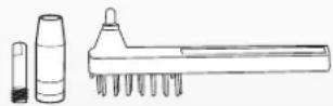
0.9mm Torch Tip, Spare Shroud & Chipping Hammer/Wire Brush
natural_image
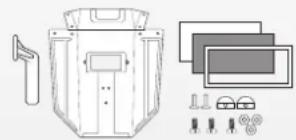
Technical line drawing of a mechanical device with exploded view and component detail (no text or symbols)Handle, Welding Mask, Lens Assembly & Fasteners
IMW-100
WARRANTY
IN ORDER TO MAKE A CLAIM UNDER THIS WARRANTY YOU MUST RETURN THE PRODUCT TO YOUR NEAREST BUNNINGS WAREHOUSE WITH YOUR BUNNINGS REGISTER RECEIPT. PRIOR TO RETURNING YOUR PRODUCT FOR WARRANTY PLEASE TELEPHONE OUR CUSTOMER SERVICE HELPLINE:
Australia: 1800 069 486
New Zealand: 0508 069 486
TO ENSURE A SPEEDY RESPONSE PLEASE HAVE THE MODEL NUMBER AND DATE OF PURCHASE AVAILABLE. A CUSTOMER SERVICE REPRESENTATIVE WILL TAKE YOUR CALL AND ANSWER ANY QUESTIONS YOU MAY HAVE RELATING TO THE WARRANTY POLICY OR PROCEDURE.
The benefits provided under this warranty are in addition to other rights and remedies which are available to you at law.
Our goods come with guarantees that cannot be excluded at law. You are entitled to a replacement or refund for a major failure and for compensation for any other reasonably foreseeable loss or damage. You are also entitled to have the goods repaired or replaced if the goods fail to be of acceptable quality and the failure does not amount to a major failure.
Generally you will be responsible for all costs associated with a claim under this warranty, however, where you have suffered any additional direct loss as a result of a defective product you may be able to claim such expenses by contacting our customer service helpline above.
3 YEAR REPLACEMENT WARRANTY\*
Your product is guaranteed for a period of 36 months from the original date of purchase. If a product is defective it will be replaced in accordance with the terms of this warranty. Warranty excludes consumable parts, for example: valve adapters and accessories.
*This product is intended for DIY use only and replacement warranty covers domestic use.
WARNING
The following actions will result in the warranty being void.
- If the tool has been operated on a supply voltage other than that specified on the tool.
- If the tool shows signs of damage or defects caused by or resulting from abuse, accidents or alterations.
- Failure to perform maintenance as set out within the instruction manual.
- If the tool is disassembled or tampered with in any way.
• Professional, industrial or high frequency use.
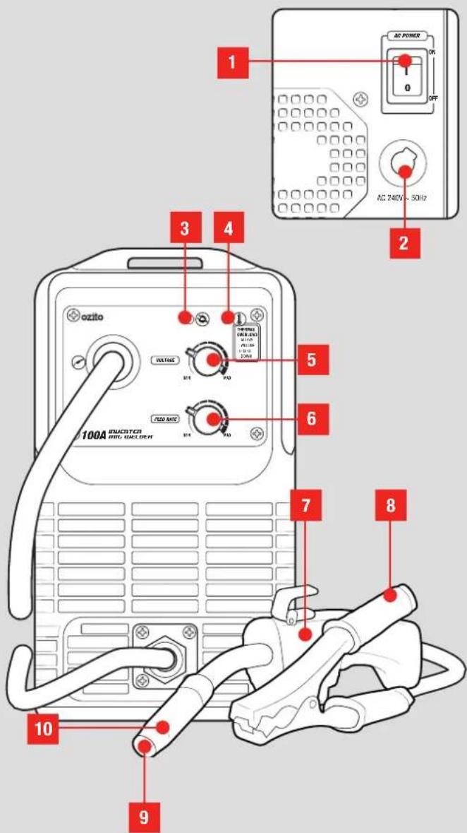
KNOW YOUR PRODUCT
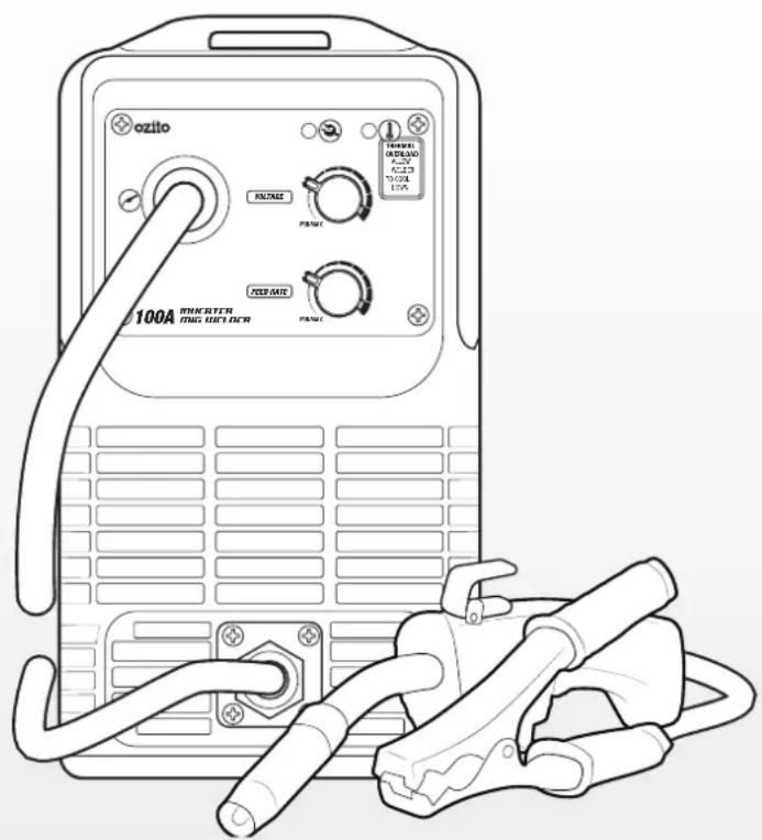
SELF SHIELDED FLUX CORED INVERTER ARC WELDER
-
On/Off Switch
-
Feed Rate Control Dial
-
AC Power Cord
-
Torch
-
Power ON LED
-
Earth Clamp
-
Thermal Overload LED
-
Torch Tip
-
Voltage Control Dial
-
Torch Shroud
ONLINE MANUAL
Scan this QR Code with your mobile device to take you to the online manual.

YEAR REPLACEMENT WARRANTY*

SETUP & PREPARATION
1. BEFORE STARTING
Safety Precautions
- Read all safety warnings and all instructions before use. Failure to follow the warnings and instructions may result in electric shock, fire and/or serious injury.
- Always wear appropriate protective equipment when welding. These include: welding helmets, overalls, welding gloves, closed shoes, leather apron, sock protectors. Overalls should be of the type designed to be buttoned at the wrists and the neck.
- Remove loose clothing and accessories and ensure any loose hair is tied up or tucked away.
- Toxic gases are given off during the welding process, which may collect in the welding area. Always ensure to weld in a well-ventilated area and use a fume extractor when required.
- The electric arc generated by the welding process gives direct heat and ultraviolet radiation. It is essential that the eyes of the operator and any bystanders are protected from the glare during welding. ALWAYS use a face shield or welding helmets fitted with the correct glass filter.
- Inspect the welder, welding torch and all connecting wires for damage / worn insulation before each use and if any damage is found, replace the damaged parts before use.
- Parts of the welding torch and welding material can be extremely hot immediately after welding. Wait for the electrode and the material to cool down before handling and always ensure welding gloves are worn when handling hot materials.

WARNING! ENSURE ALL OIL, PETROL AND FLAMMABLE CONTAINERS HAVE BEEN REMOVED FROM THE WELDING AREA.
2. ASSEMBLY 3. SETTING UP THE WELDING WIRE

WARNING! ENSURE THE TOOL IS TURNED OFF AND DISCONNECTED FROM THE POWER SUPPLY BEFORE PERFORMING ANY OF THE FOLLOWING OPERATIONS.
Assembling The Welding Mask
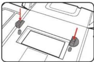
The included welding mask must be fitted with the lens assembly and handle before using it for welding.
- Push the plastic pins into the mask from the outside and secure it with the retaining clips from the inside of the mask. Rotate the retaining clips so that the lens assembly can be inserted.
natural_image
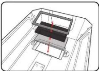
Diagram of a vehicle interior with two red arrows pointing to specific components (no text or labels)- Insert the clear glass into the recess of the welding mask, then the dark safety glass and finally the plastic lens frame.
natural_image
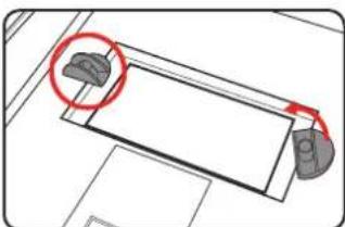
Technical line drawing of a mechanical assembly with no visible text or symbols- Rotate the retaining clips to lock the lens assembly in place.
natural_image
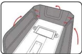
Top-down diagram of a mechanical component with a red circle highlighting a specific area (no text or symbols present)- Bend the sides and top of the welding mask inwards and clip it together at the corners.
natural_image
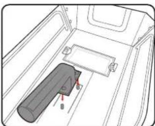
3D diagram of a vehicle chassis with red directional arrows indicating rotation (no text or symbols)- Insert the 3 screws into the handle mounting holes from the outside. Fit the handle onto the screws on the inside of the mask and secure them using the 3 nuts.
natural_image
Technical line drawing of a vehicle interior showing a cylindrical component and labeled parts (no text or symbols)
WARNING! ALWAYS ENSURE THE WELDER IS SWITCHED OFF WHEN REPLACING THE WELDING WIRE &/OR MAKING ADJUSTMENTS TO THE WIRE DRIVE SYSTEM.
Installing A Wire Spool
The welder can be fitted with 0.8mm or 0.9mm gasless welding wire. Welding wire up to 1kg can be fitted to this welder.
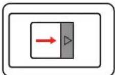
- Push the latch towards the back of the welder unit and lift the top cover.
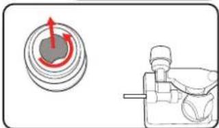
- Undo the spool nut then remove the spring and spool plate.
natural_image
Diagram showing a circular component with red arrows and a mechanical tool (no text or symbols)Note: Before first use, be sure to remove all the packaging from the included wire spool.

WARNING! DO NOT PULL THE END OF THE WIRE FREE UNTIL YOU ARE READY TO THREAD THE MACHINE. THE SPOOL IS COILED UNDER TENSION AND WILL UNWIND IF RELEASED WHICH MAY CAUSE TANGLING & WIRE FEED ISSUES DURING USE.
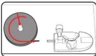
- Place the spool onto the spindle so that the wire unwinds in an anti-clockwise direction.
natural_image
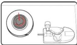
Diagram showing a circular object with red arrows and a mechanical device (no text or symbols)- Replace the spool plate and spring, then lock it in place with the spool nut.
natural_image
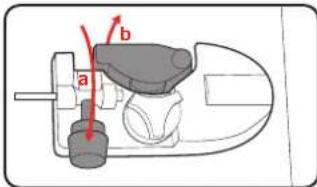
Diagram showing a circular component with red internal lines and a seated figure in a chair (no text or symbols)- Flip the tension adjustor bar up and swing the pressure arm away from the roller guide.
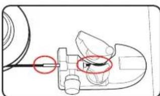
- While maintaining a firm hold of the wire end, pull it free of the spool and thread it through the feed tube and into the cable housing.
natural_image
Mechanical assembly diagram showing a component with a red circle highlighting a specific area (no text or symbols present)- Rotate the pressure arm back into place and flip the tension adjustor bar back to lock it in place.
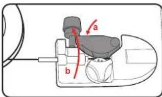

WARNING! THE POWER SUPPLY FOR THIS PRODUCT SHOULD BE PROTECTED BY A RESIDUAL CURRENT DEVICE (RATED AT 30mA OR LESS). A RESIDUAL CURRENT DEVICE REDUCES THE RISK OF ELECTRIC SHOCK.
Loading The Torch
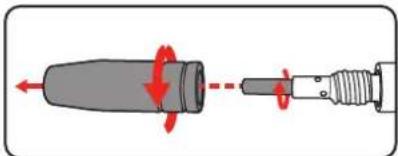
- Twist the shroud clockwise and pull it off the torch, then unscrew the torch tip.
natural_image
Diagram showing a connector with red arrows indicating rotation and movement, no text or symbols presentNote: The 0.8mm
torch tip is fitted by default. Swap it for the included 0.9mm tip if different welding wire is used instead.
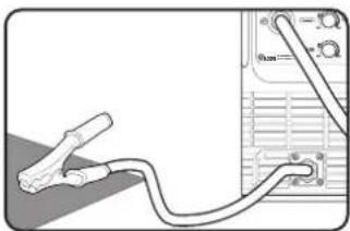
- Place the earth clamp out of the way, away from the torch and welder unit on a non-conductive surface such as a wooden workbench.
natural_image
Diagram showing a cable being inserted into a device with a connector (no text or symbols visible)
WARNING! ENSURE THAT YOU DO NOT MAKE CONTACT WITH THE EARTH CLAMP AT ANY STAGE WHEN FEEDING THE WIRE THROUGH THE TORCH. THE ELECTRODE WIRE WILL BE AT WELDING VOLTAGE WHilst IT IS FED THROUGH. KEEP THE TORCH AWAY FROM YOUR EYES & FACE.
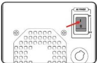
- Plug the power cord into a power supply and flip the on/off switch to the on position.
- Ensure the torch lead is straight as you depress the trigger to feed the wire through.
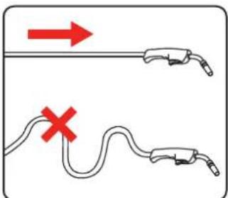
- Once the wire protrudes from the end of the torch, release the trigger.
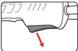
- Hold the torch 2 to 3 inches away from a non-conductive hard surface and depress the trigger.
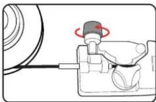
If the wire stops against the surface without bending, switch off the welder and tighten the feed tensioner slightly by turning it clockwise.
natural_image
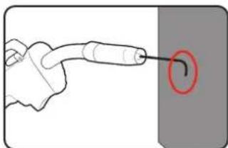
Diagram of a mechanical device with a rotating knob and connecting rod (no text or symbols)- The tension is correctly set if the wire fed through the torch bends when it encounters the hard surface. Repeat step 6 until this happens.
natural_image
Illustration of a hand holding a pen with a red circle highlighting a curved object (no text or symbols)- Switch the welder off.
- Fit the appropriate torch tip by screwing it on clockwise. Push and twist the shroud clockwise as well to fit it on the torch.
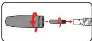

WARNING! ONLY USE THE 0.8MM TIP WITH 0.8MM WELDING WIRE OR THE 0.9MM TIP WITH 0.9MM WIRE. INCORRECT TIP USAGE CAN CAUSE SPOOLING ISSUES & DAMAGE THE MACHINE.
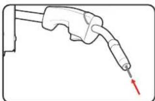
- Leave 10mm protruding from the end of the torch and cut off any excess welding wire.
natural_image
Illustration of a hand holding a pen or probe with a red arrow pointing to the tip (no text or symbols present)Note: Do not cut the wire at an angle. The end of the welding wire should be flat and have no burrs or sharp edges. File down the end or cut it again if necessary.
Welding Wire Settings Selection
There are many variables that you will need to take into account when choosing your welding wire size and type. Below are some of the factors that should be considered:
- Type & thickness of the material to be welded
- Position and type of welding joint
• Maximum welding capacity of your welder - How much penetration will be required for strength
• Type of bead desired for the weld - Whether you are using a shielding gas or not
| WIRE DIAMETER | SUGGESTED SETTINGS | STEEL THICKNESS (MM) | |
| 1.2 1.5 2.0 3.0 | |||
| 0.8mm | Voltage 1-2 2-3 4-6 7-10 | ||
| Wire Speed 1-2 2-3 4-7 8-10 | |||
| 0.9mm | Voltage - 1-2 3-6 7-10 | ||
| Wire Speed - 4-5 5-6 6-7 | |||
Note: The above chart is only intended as a general guide. Proper welding will also depend on how close the torch is held to the material and the speed it is moved along the weld. Always test new settings on a scrap piece of material first. Proper welding takes good technique and practice.
Aluminium Welding
For aluminium welding, aluminium wire must be used. The workpiece must be thoroughly cleaned with a stainless steel wire brush to remove oxides and impurities from the weld surface.
Depending on the thickness of the workpiece, it also may require additional heat sinks to be attached to the workpiece. Ensure proper tip-to-work distance to prevent wire burning back to the contact tip.
4. CONTROLS

WARNING! ENSURE APPROVED PROTECTIVE CLOTHING & A WELDING HELMET/MASK IS WORN AT ALL TIMES TO PROTECT YOUR FACE & EYES FROM ARC UV RADIATION & SPARKS.
ON/Off Switch
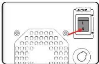
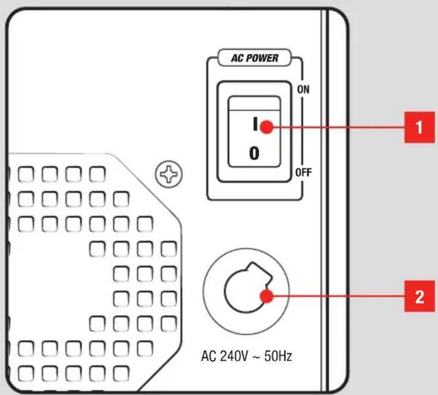
The on/off switch is located on the rear of the welder.
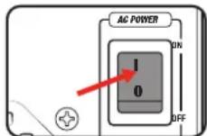
- Press the on/off switch into the on position 'I' to switch the unit on.
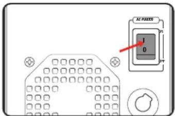
- To switch the unit off, press the switch to the '0' position.
Note: Check the rating of the circuit breaker on the supply and other appliances connected to the circuit. The welder is a high powered device and it is recommended that it is the only appliance on the circuit to ensure it has enough power to operate.
Note: If a 15A circuit is available, it is recommended that the welder be connected to this.

WARNING! DO NOT LEAVE THE SWITCH IN THE ON POSITION WHEN THE UNIT IS NOT IN USE AS THIS POSES THE RISK OF ELECTROCUTION OR ACCIDENTS HAPPENING FOR THE NEXT USER.
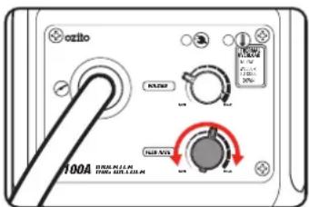
Wire Feed Speed
The wire feed speed should be adjusted to suit the application and material being welded. Refer to the Welding Wire Settings Selection Table as a guide.
Note: Always test settings on a scrap piece of material first.
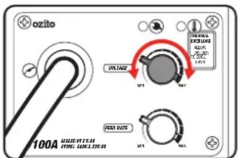
Variable Voltage
The voltage should be set according to the application, material being welded and wire feed speed.
- The voltage can be increased or decreased by turning the voltage control dial.

WARNING! IF THE WELDER OVERHEATS & THE THERMAL OVERLOAD PROTECTION ENGAGES, DO NOT TURN OFF THE WELDER AS THE FAN WILL ASSIST IN SPEEDING UP THE COOLING TIME.

WARNING! ENSURE THE CLAMP & THE TORCH IS AWAY FROM THE WELDING MATERIAL & PLACED ON A NON-CONDUCTIVE SURFACE WHILE THE OVERLOAD PROTECTION IS ENGAGED.
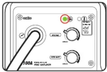
Power LED Light
- The ON LED illuminates when the power cord is connected to a live mains outlet and the on/off switch is in the on position.
Note: The cooling fan will operate when the unit is switched on.
Thermal Overload Protection
All Welders have a feature called a duty cycle. Duty cycle on a welder refers to the time in which the welder operates during normal welding. A welder can only weld for a certain continuous period of time before it requires to cool down.
If the internal components of the welder should become hot the welder could overheat. If the welder overheats the Thermal Overload Protection feature will automatically shut down the welder.
THIS CAN OCCUR IN HEAVY USE AND DOES NOT INDICATE A FAULT.
The Welder will cease to weld and the Thermal Overload LED light will turn on. This LED indication light is just to inform you that your welder is becoming too hot and requires a cool down to protect the internal components of the welder.
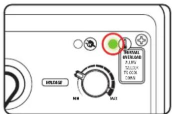
Do Not turn your welder Off as the welder has an internal cooling fan and this will assist your welder to cool down quicker. Reducing the cooling time will enable you to get back to your welding job quicker.
Depending on how many Amps or how heavy the welding you are doing the cooling time may take up to 10 minutes for your welder cool down so you can return to your welding job.
Duty cycle % as referenced on the rating label are based on 10 minute intervals. For instance with a 20% duty cycle, one can weld continuously for 2 minutes, but then must wait 8 minutes for the welder to cool.
Lower current levels have longer duty cycles.
6. WELDING5. INDICATOR LEDS
Welding
- Ensure that the workpiece is clamped down securely, is cleaned and prepared for welding.
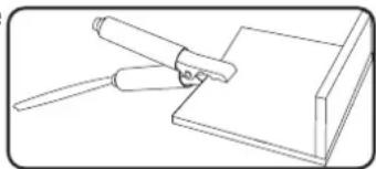
- Attach the earth clamp to the workpiece ensuring there is good metal to metal contact.
natural_image
Simple line drawing of a tool interacting with a rectangular object (no text or symbols)Note: Prior to connecting the earth clamp it may be
necessary to clean the surface of the work piece using the metal brush. Clamp it where it will not be in the way. This clamp provides an earth connection back to the welder.
- Switch the welder on and position the welding mask in front of your eyes.
- Position the wire tip approximately 8mm from the workpiece at a 20° angle from the vertical in the direction of movement.
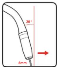
Note: Leaving a 10mm length of protruding wire and holding the torch so that the wire touches the workpiece is a good way to estimate the proper placement.
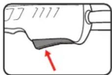
- Squeeze the torch trigger to start the weld.
Welding Tips
Travel Speed
There are a range of welding movements used in welding. Generally some form of zig-zag motion is used to ensure the arc acts against both sheets to be welded.
The torch should be moved along at a smooth speed that will give the size of run required. At the same time, the wire is fed downwards to keep the correct welding distance at all times. Excessive travel speeds lead to poor fusion and lack of penetration. While too slow a rate of travel may damage the work piece and can lead to burning a hole through the material.
Electricity
The electricity flows through the wire and will not leave the wire unless it is near an earthed object. Electricity always finds the fastest path to the earth. When the earth cable clamp is connected to the metal work piece a direct earth connection is created back to the welder. When the wire touches or is near the earthed work piece when the trigger is squeezed, electricity flows through the wire, the metal work piece and then through the earth cable straight back to the welder.
7. TROUBLESHOOTING

WARNING! THE WELDER SHOULD ONLY BE SERVICED BY QUALIFIED PERSONNEL.
| Symptom | Possible Cause | Suggested Solution |
| No Power | On/off switch is off | Check on/off switch is in the on position. |
| Power supply fault | Test power supply with another product, avoid using extension leads. | |
| Circuit breaker tripped | Check the rating of the circuit breaker on the supply and other appliances connected to the circuit.The welder is a high power device and it is recommended that it is the only appliance on the circuit to ensure it has enough power to operate. | |
| Difficulty starting arc | Inadequate earth clamp connection | Check earth clamp has good connection to material being welded. Surface for clamp connections needs to be bare metal, remove rust or paint. |
| Welding technique | Hold torch at correct angle, practice on scrap material. | |
| Welder cuts out | Thermal overload active | The thermal overload light will light up and the welder will not operate until cooled down and the light goes out. This is normal in heavy welding, allow the unit to cool down. |
| Sticking wire | Incorrect settings | Increase voltage & wire feed speed to recommended setting. |
| Coated work piece | Clean weld area to bare metal. | |
| Incorrect wire type/ size | Check that the wire type and size is appropriate for the material being welded. | |
| Excessive welding wire consumption | Welding voltage too high | Reduce voltage. |
| Wire size too small for material | Change to larger wire size. |
DESCRIPTION OF SYMBOLS
| V | Volts | Hz | Hertz | |
| ~ | Alternating Current Direct Current (DC) | Ipeak | ||
| /min | Revolutions or reciprocations per minute | Ipeak | Watts | |
| ∅ | Diameter | U | Non-load voltage | |
| U_1 | Rated input voltage | Ipeak | On-load voltage | |
| I_1max | Rated maximum input current | IpeakT | Maximum effective input current | |
| I_2 | Current rating | Ipeak | Load duration rate | |
| IP | Protection class | Ipeak | Used in an environment that has high risk of electric shock | |
| 1~50Hz | Single phase AV power & rated frequency | IpeakT | Self shielded flux cored arc welding | |
| IpeakT | ||||
| Wear coveralls | IpeakT | Wear appropriate face shield | ||
| Wear close-toed shoes Wear welding | IpeakT | |||
| Regulatory Compliance Mark (RCM) | IpeakT | Warning | ||
| H | Insulation grade | IpeakT | Do not operate in rain | |
| Read Instruction Manual | ||||
| 1~F1F2 | Single phase transformer - rectifier | |||
SPARE PARTS
Spare parts can be ordered from the Special Orders Desk at your local Bunnings Warehouse.
For further information, or any parts not listed here, visit
www.ozito.com.au or contact Ozito Customer Service:
Australia 1800 069 486 New Zealand 0508 069 486
E-mail: enquiries@ozito.com.au
EQUIPMENT CLASSIFICATION
Additional Specifications
Duty Cycle: 20% @100A (19V DC)
60% @58A (16.9V DC)
100% @45A (16.3V DC)
The duty cycle was determined at 40°C by simulation.
l,max: 15.0A
I_1 eff: 6.7A
Welder Characteristics: Constant Voltage-Flat Characteristic
Carrying Method: Strap
Cooling System: Fan Cooling
Heating tests were conducted at ambient temperature.
Power Cable: 3 x 1.5-2mm ^2
Welding Cable: 1 x 10mm ^2
Recommended External Fuse: 16A.
This product is classified as Group 2, Class A welding equipment.
- Group 2 - This product generates radio frequency energy in the frequency range 9KHz to 400GHz.
- Class A - This product is intended for use in an industrial environment. Caution: This equipment is not intended for use in residential environments and may not provide adequate protection to radio reception in such environments.
CARING FOR THE ENVIRONMENT
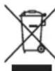
Power tools that are no longer usable should not be disposed of with household waste but in an environmentally friendly way. Please recycle where facilities exist. Check with your local council authority for recycling advice.

Recycling packaging reduces the need for landfill and raw materials. Reuse of recycled material decreases pollution in the environment.
Please recycle packaging where facilities exist. Check with your local council authority for recycling advice.
ozito
SELF SHIELDED FLUX CORED INVERTER ARC WELDER
100A
MAINTENANCE MANUAL
3
YEAR
REPLACEMENT WARRANTY*
IMW-100
CONTENTS
Know Your Product ...... Page 2
Electrical Safety Page 4
General Power Tool Safety Warnings Page 5
Welder Safety Warnings...... Page 7
Circuit Diagram Page 10
Maintenance Page 12
KNOW YOUR PRODUCT
SELF SHIELDED FLUX CORED INVERTER ARC WELDER
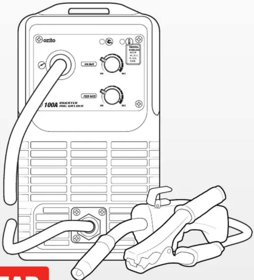
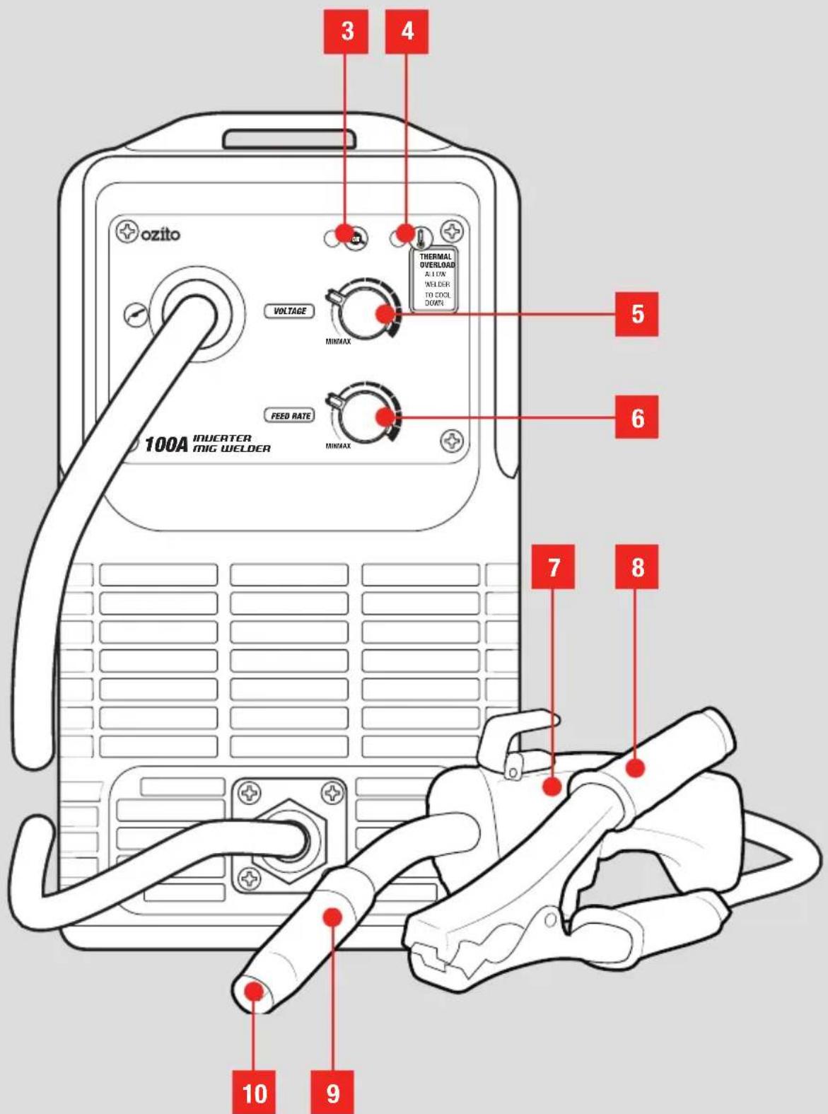
- On/Off Switch
- AC Power Cord
- Power ON LED
- Thermal Overload LED
- Voltage Control Dial
- Feed Rate Control Dial
- Torch
- Earth Clamp
- Torch Shroud
- Torch Tip
ONLINE MANUAL
Scan this QR Code with your mobile device to take you to the online manual.
3 YEAR REPLACEMENT WARRANTY*


ELECTRICAL SAFETY

WARNING! When using mains-powered tools, basic safety precautions, including the following, should always be followed to reduce risk of fire, electric shock, personal injury and material damage.
Read the whole manual carefully and make sure you know how to switch the tool off in an emergency, before operating the tool.
Save these instructions and other documents supplied with this tool for future reference.
This tool has been designed for 230V and 240V only. Always check that the power supply corresponds to the voltage on the rating plate.
Note: The supply of 230V and 240V on Ozito tools are interchangeable for Australia and New Zealand.
Using an Extension Lead
Always use an approved extension lead suitable for the power input of this tool. Before use, inspect the extension lead for signs of damage, wear and ageing. Replace the extension lead if damaged or defective.
When using an extension lead on a reel, always unwind the lead completely. Use of an extension lead not suitable for the power input of the tool or which is damaged or defective may result in a risk of fire and electric shock.
The power supply for this product must be protected by a residual current device (rated at 30mA or less). A residual current device reduces the risk of electric shock.

WARNING! Read all safety warnings and all instructions. Failure to follow the warnings and instructions may result in electric shock, fire and/or serious injury.
Save all warnings and instructions for future reference. The term “power tool” in the warnings refers to your mains-operated (corded) power tool or battery-operated (cordless) power tool.
- Work area safety
a. Keep work area clean and well lit. Cluttered or dark areas invite accidents.
b. Do not operate power tools in explosive atmospheres, such as in the presence of flammable liquids, gases or dust. Power tools create sparks which may ignite the dust or fumes.
c. Keep children and bystanders away while operating a power tool. Distractions can cause you to lose control.
- Electrical safety
a. Power tool plugs must match the outlet. Never modify the plug in any way. Do not use any adapter plugs with earthed (grounded) power tools. Unmodified plugs and matching outlets will reduce risk of electric shock.
b. Avoid body contact with earthed or grounded surfaces, such as pipes, radiators, ranges and refrigerators. There is an increased risk of electric shock if your body is earthed or grounded.
c. Do not expose power tools to rain or wet conditions. Water entering a power tool will increase the risk of electric shock.
d. Do not abuse the cord. Never use the cord for carrying, pulling or unplugging the power tool. Keep cord away from heat, oil, sharp edges or moving parts. Damaged or entangled cords increase the risk of electric shock.
e. When operating a power tool outdoors, use an extension cord suitable for outdoor use. Use of a cord suitable for outdoor use reduces the risk of electric shock.
- Personal safety
a. Stay alert, watch what you are doing and use common sense when operating a power tool. Do not use a power tool while you are tired or under the influence of drugs, alcohol or medication. A moment of inattention while operating power tools may result in serious personal injury.
b. Use personal protective equipment. Always wear eye protection. Protective equipment such as dust mask, non-skid safety shoes, hard hat, or hearing protection used for appropriate conditions will reduce personal injuries.
c. Prevent unintentional starting. Ensure the switch is in the off-position before connecting to power source and/or battery pack, picking up or carrying the tool. Carrying power tools with your finger on the switch or energising power tools that have the switch on invites accidents.
d. Remove any adjusting key or wrench before turning the power tool on. A wrench or a key left attached to a rotating part of the power tool may result in personal injury.
e. Do not overreach. Keep proper footing and balance at all times. This enables better control of the power tool in unexpected situations.
f. Dress properly. Do not wear loose clothing or jewellery. Keep your hair, clothing and gloves
away from moving parts. Loose clothes, jewellery or long hair can be caught in moving parts.
g. If devices are provided for the connection of dust extraction and collection facilities, ensure these are connected and properly used. Use of dust collection can reduce dust-related hazards.
h. Do not let familiarity gained from frequent use of tools allow you to become complacent and ignore tool safety principles. A careless action can cause severe injury within a fraction of a second.
- Power tool use and care
a. Do not force the power tool. Use the correct power tool for your application. The correct power tool will do the job better and safer at the rate for which it was designed.
b. Do not use the power tool if the switch does not turn it on and off. Any power tool that cannot be controlled with the switch is dangerous and must be repaired.
c. Disconnect the plug from the power source and/or the battery pack from the power tool before making any adjustments, changing accessories, or storing power tools. Such preventive safety measures reduce the risk of starting the power tool accidentally.
d. Store idle power tools out of the reach of children and do not allow persons unfamiliar with the power tool or these instructions to operate the power tool. Power tools are dangerous in the hands of untrained users.
e. Maintain power tools. Check for misalignment or binding of moving parts, breakage of parts and any other condition that may affect the power tool's operation. If damaged, have the power tool repaired before use. Many accidents are caused by poorly maintained power tools.
f. Keep cutting tools sharp and clean. Properly maintained cutting tools with sharp cutting edges are less likely to bind and are easier to control.
g. Use the power tool, accessories and tool bits etc. in accordance with these instructions, taking into account the working conditions and the work to be performed. Use of the power tool for operations different from those intended could result in a hazardous situation.
h. Keep handles and grasping surfaces dry, clean and free from oil and grease. Slippery handles and grasping surfaces do not allow for safe handling and control of the tool in unexpected situations.
- Service
a. Have your power tool serviced by a qualified repair person using only identical replacement parts. This will ensure that the safety of the power tool is maintained.

WELDER SAFETY WARNINGS

WARNING! The appliance is not to be used by persons (including children) with reduced physical, sensory or mental capabilities, or lack of experience and knowledge, unless they have been given supervision or instruction.
Young children should be supervised to ensure that they do not play with the appliance.
Before connecting a tool to a power source (mains switch power point receptacle, outlet, etc.) be sure that the voltage supply is the same as that specified on the nameplate of the tool. A power source with a voltage greater than that specified for the tool can result in serious injury to the user, as well as damage to the tool. If in doubt, do not plug in the tool. Using a power source with a voltage less than the nameplate rating is harmful to the motor.
- Under no circumstances should the housing of the welder be opened.
- Never attempt to repair or modify the welder.
- Screen off the work place to protect others working nearby from UV rays.
- Do not use the welder in damp or wet conditions.
- Do not use the welder for pipe thawing.
- Do not use cables with worn insulation or loose connections.
- Disconnect from the power supply before replacing welding wire.
- Avoid direct contact with the welding circuit.
- Never pull on the welding leads or the power cord to move the welder.
- Ensure the welding materials are securely clamped down/fastened before welding.
- Always place welding torch and clamp on flat stable surface when not in use.
- Never put the welding torch down until the welder is switched off.
- Store all spare welding wire in a safe place, away from the welding area.
- Welding materials with contaminated surfaces may generate toxic fumes. Ensure the surface is clean before welding. Avoid operating on materials cleaned with chlorinated solvents or near such solvents.
- Do not weld metal equipment that holds/contains flammable materials, gases or liquid combustibles.
- Zinc-plated or galvanized material should not be welded as the fumes created are highly toxic.
- Do not weld painted / oiled materials. Ensure all welding surfaces are stripped / cleaned down to the bare metal.
- Always check the welding material before welding to see if it the material is compatible with self shielded flux cored arc welding.
- Do not use the welder near food or food preparation areas.
- Do not weld cadmium plated steel. Always check the welding material for control measure before welding
- Use only one welder to weld at all times.
- Only connect the welding machine to an earthed electric network.
- Never touch live parts or the welding rod with wet hands/gloves/clothing.
- Ensure there is a level of insulation (welding mats) between yourself and the ground as well as the workpiece when welding.
- Ensure cables or welding electrode holder are not squashed by heavy objects and that they are not exposed to sharp edges or a hot work piece.
- Turn off the welder when it is not in use.
Important Information about Radio Electromagnetic Compatibility
- Extra precautions for Electromagnetic Compatibility may be required when this Welding Power Source is used in a domestic situation.
- It is the user's responsibility to install and use the equipment properly in accordance with the instructions issued by the manufacturer. If electromagnetic disturbances are detected then it shall be the responsibility of the user of the equipment to resolve the situation with the following guidelines.
Precautions to consider in the surrounding area that may cause/be affected by electromagnetic disturbances
- Other supply cables or signal cables in close proximity to the welding equipment;
• Radio and television transmitters and receivers;
• Computer or electronic equipment; - Personal medical devices (pacemakers and hearing aids).
Methods of reducing electromagnetic disturbances
- If interference occurs when the equipment is connected to the mains power supply in a residential (domestic) low voltage power network, an electromagnetic filter may be required.
- The Welding cables should not be modified and kept as short as possible.
- Nearby cables and equipment may need to be moved or shielded.
Fumes
- Toxic gases are given off during the welding process, which may collect in the welding area if the ventilation is poor. Be alert at all times to the possibility of fume build-up.
- Provide adequate ventilation or a means for removal of the welding fumes produced (forced circulation using a blower or fan). In small or confined areas use a fume extractor.
Glare
- The electric arc generated by the process gives direct heat and ultraviolet radiation. It is essential that the eyes of the operator and bystanders are protected from the glare during welding.
- ALWAYS USE A FACESHIELD OR WELDING HELMET FITTED WITH THE CORRECT GLASS FILTER.
Position and Handling
- Position the welding machine on a horizontal surface that is able to support the weight: otherwise (e.g. inclined or uneven floors etc.) there is danger of overturning.
- The welder MUST NOT be supported by the operator (e.g using belts). The operator MUST NOT BE ALLOWED to weld in raised positions unless safety platforms are used.
- Do not weld materials in overhead positions.
Heat
- It is desirable that welding gloves are worn whilst welding. They will protect the hands from ultraviolet radiation and direct heat of the arc.
Dress
- In addition to face shield, welding gloves and overalls, other types of protective clothing should be worn when welding. Additional protective clothing such as a leather apron, sock protectors and a hat
will all assist in reducing any injuries due to heat, sparks and slag produced during welding.
- OVERALLS should also be worn. They should be of type designed to be buttoned at the wrists and the neck.
- Avoid exposing skin as UV rays are produced by the arc.
Spatter and fire
- Welding spark may cause accidental fire, please make sure that there is no welding working position nearby the welding working position, equip with the fire extinguisher all around.
- Welding is always classified as hot work, so pay attention to fire safety regulations during welding and after it.
- Remember that fire can break out from sparks even several hours after the welding work is completed.
- Protect the environment from welding splatter. Remove flammable materials, such as flammable fluids, from the welding vicinity and supply the welding site with adequate fire fighting equipment.
- In special welding jobs, be prepared for hazards such as fire or explosion when welding container type work pieces.
- Never direct the spark spray or cutting spray of a grinder toward the welding machine or flammable materials.
- Beware of hot objects or splatter falling on the machine when working above the machine.
- Welding in flammable or explosive sites is absolutely forbidden.
CIRCUIT DIAGRAM
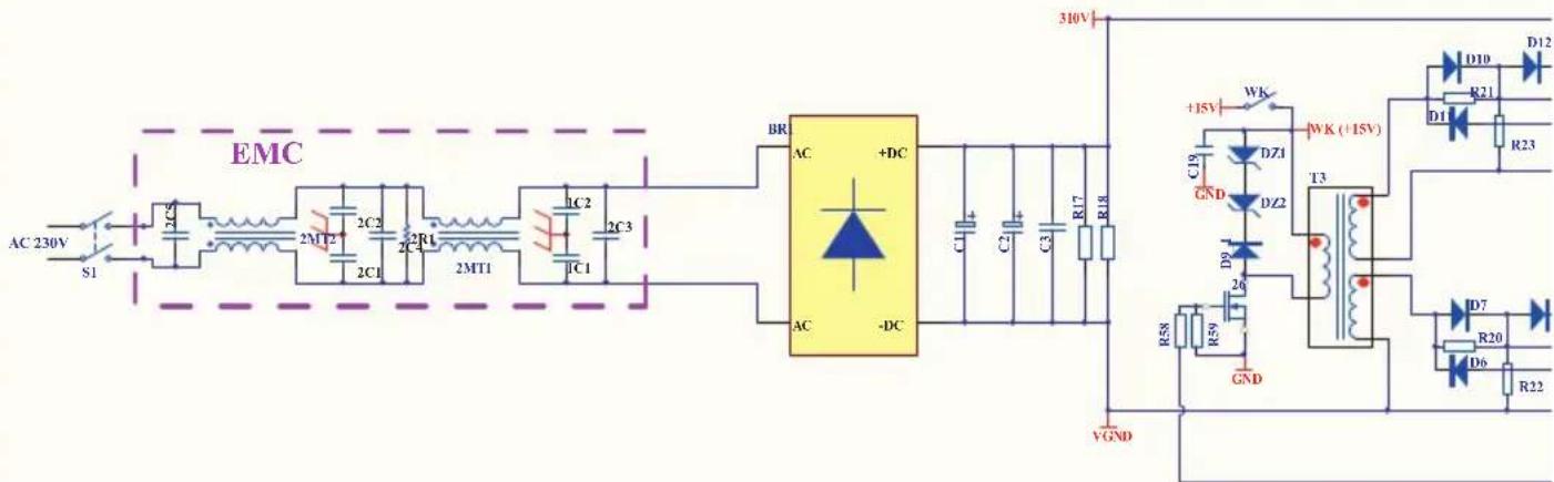
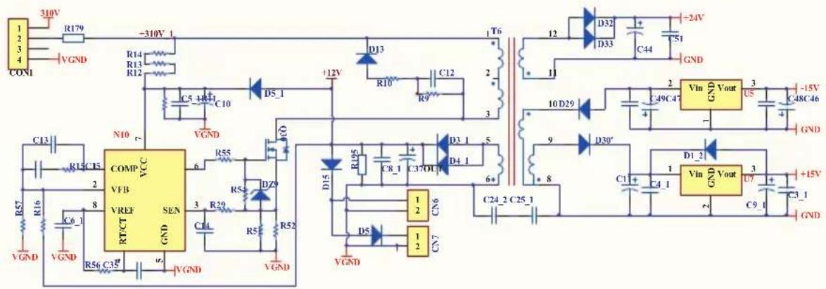
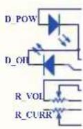

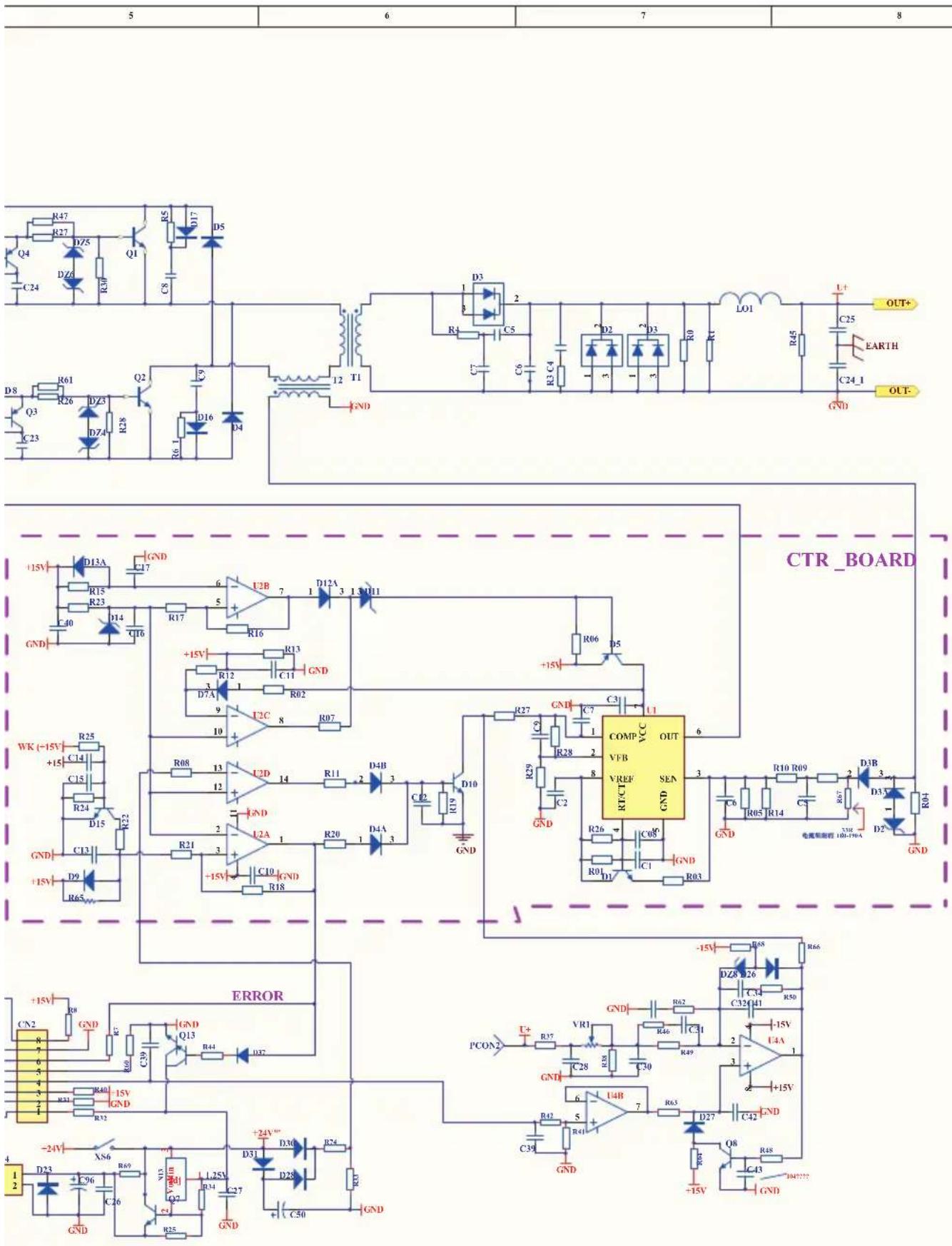

WARNING! BEFORE CLEANING THE APPLIANCE OR CARRYING OUT ANY MAINTENANCE PROCEDURE, MAKE SURE THAT IT IS DISCONNECTED FROM THE POWER SUPPLY TO PREVENT ACCIDENTAL STARTING.
Cleaning
- We recommend that you clean the appliance immediately after you use it.
- Keep the safety devices free of dirt and dust as much as possible. Wipe the equipment with a clean cloth.
- Clean the appliance regularly with a damp cloth and some soft soap. Do not use cleaning agents or solvents; these may be aggressive to the plastic parts in the appliance. Ensure that no water can get into the interior of the appliance.
Storage
Pull the mains plug out of the socket, switch off the tool and make sure that it is secured in such a way that it cannot be started up again by any unauthorised person.
Store the tool in a dry location which is not accessible to unauthorised persons.
Supply Cords
If replacement of the supply cord is necessary, this has to be done by a certified electrician in order to avoid a safety hazard.
Note: Ozito Industries will not be responsible for any damage or injuries caused by the repair of the tool by an unauthorised person or by mishandling of the tool.
- WARRANTY
- YEAR REPLACEMENT WARRANTY\*
- WARNING
- KNOW YOUR PRODUCT
- SELF SHIELDED FLUX CORED INVERTER ARC WELDER
- ONLINE MANUAL
- SETUP & PREPARATION
- BEFORE STARTING
- Safety Precautions
- ASSEMBLY 3. SETTING UP THE WELDING WIRE
- Assembling The Welding Mask
- Installing A Wire Spool
- Loading The Torch
- Welding Wire Settings Selection
- Aluminium Welding
- CONTROLS
- ON/Off Switch
- Wire Feed Speed
- Variable Voltage
- Power LED Light
- Thermal Overload Protection
- THIS CAN OCCUR IN HEAVY USE AND DOES NOT INDICATE A FAULT.
- WELDING5. INDICATOR LEDS
- Welding
- Welding Tips
- Travel Speed
- Electricity
- TROUBLESHOOTING
- DESCRIPTION OF SYMBOLS
- SPARE PARTS
- EQUIPMENT CLASSIFICATION
- Additional Specifications
- CARING FOR THE ENVIRONMENT
- ozito
- CONTENTS
- ELECTRICAL SAFETY
- Using an Extension Lead
- WELDER SAFETY WARNINGS
- Important Information about Radio Electromagnetic Compatibility
- Precautions to consider in the surrounding area that may cause/be affected by electromagnetic disturbances
- Methods of reducing electromagnetic disturbances
- Fumes
- Glare
- Position and Handling
- Heat
- Dress
- Spatter and fire
- CIRCUIT DIAGRAM
- Cleaning
- Storage
- Supply Cords
Brand : Ozito
Model : IMW-100
Category : Welding machine