MWR-135 - Welding machine Ozito - Free user manual and instructions
Find the device manual for free MWR-135 Ozito in PDF.


| Product Type | MIG Welder (Welding Machine) |
| Model | MWR-135 |
| Welding Current Range | 40 - 120 A |
| Welding Wire Size (Solid) | 0.6 - 0.8 mm |
| Welding Wire Size (Flux-Cored) | 0.8 - 0.9 mm |
| Duty Cycle | 60% @ 40A, 10% @ 120A |
| Insulation Class | Earthed Appliance (Class I) |
| Wire Spool Weight Capacity | 0.2 kg to 5 kg |
| Weight (Tool Only) | 22.2 kg |
| Input Voltage | 230V / 240V AC, 50 Hz |
| Warranty | 3 Year Replacement Warranty |
| What's in the Box | MIG Welder, Welding Mask, Chipping Hammer / Wire Brush, Earth Clamp, Terminal Spanner |
| Welding Modes | Gasless (FCAW) and Gas Shielded (MIG) |
| Wire Feed Speed Control | Adjustable dial, 0-10 m/min |
| Output Voltage Settings | 5 levels via dial (40A/16V to 120A/19.8V) |
| Overload Protection | Self-resetting thermostat with LED indicator |
| Cooling | Internal cooling fan |
| Spare Parts Available | Welding torch assembly, on/off switch, drive rollers, pressure roller (contact Bunnings or Ozito) |
| Safety Features | RCD recommended, thermal overload cut-out, earth clamp |
| Accessories Included | Welding mask, chipping hammer/wire brush, earth clamp, terminal spanner |
Frequently Asked Questions - MWR-135 Ozito
User questions about MWR-135 Ozito
0 question about this device. Answer the ones you know or ask your own.
Ask a new question about this device
Download the instructions for your Welding machine in PDF format for free! Find your manual MWR-135 - Ozito and take your electronic device back in hand. On this page are published all the documents necessary for the use of your device. MWR-135 by Ozito.
USER MANUAL MWR-135 Ozito
Welding Current: 40 - 120A
Welding Wire Size: 0.6-0.8mm General Wire,
0.8-0.9mm Flux-Cored Wire
Duty Cycle: 60%@40A, 10%@120A
Insulation Type: Earthed Appliance (Class I)
Wire Spool Weight: 0.2kg to 5kg
Weight (tool only): 22.2kg
ozito.com.au
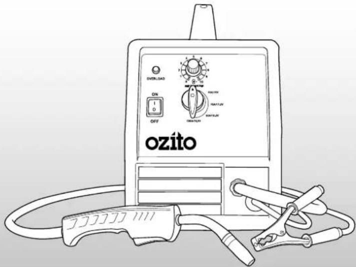
WHAT'S IN THE BOX
MIG Welder
Welding Mask
Chipping Hammer / Wire Brush
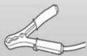
Earth Clamp
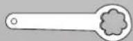
Terminal Spanner
3
YEAR REPLACEMENT WARRANTY
MWR-135
WARRANTY
IN ORDER TO MAKE A CLAIM UNDER THIS WARRANTY YOU MUST RETURN THE PRODUCT TO YOUR NEAREST BUNNINGS WAREHOUSE WITH YOUR BUNNINGS REGISTER RECEIPT. PRIOR TO RETURNING YOUR PRODUCT FOR WARRANTY PLEASE TELEPHONE OUR CUSTOMER SERVICE HELPLINE:
Australia 1800 069 486
New Zealand 0508 069 486
TO ENSURE A SPEEDY RESPONSE PLEASE HAVE THE MODEL NUMBER AND DATE OF PURCHASE AVAILABLE. A CUSTOMER SERVICE REPRESENTATIVE WILL TAKE YOUR CALL AND ANSWER ANY QUESTIONS YOU MAY HAVE RELATING TO THE WARRANTY POLICY OR PROCEDURE.
The benefits provided under this warranty are in addition to other rights and remedies which are available to you at law.
Our goods come with guarantees that cannot be excluded at law. You are entitled to a replacement or refund for a major failure and for compensation for any other reasonably foreseeable loss or damage. You are also entitled to have the goods repaired or replaced if the goods fail to be of acceptable quality and the failure does not amount to a major failure.
Generally you will be responsible for all costs associated with a claim under this warranty, however, where you have suffered any additional direct loss as a result of a defective product you may be able to claim such expenses by contacting our customer service helpline above.
3 YEAR REPLACEMENT WARRANTY
Your product is guaranteed for a period of 36 months from the original date of purchase. If a product is defective it will be replaced in accordance with the terms of this warranty.
Warranty excludes consumable parts, for example: welding masks and combination wire brush and chipping hammers.
WARNING
The following actions will result in the warranty being void.
- If the tool has been operated on a supply voltage other than that specified on the tool.
- If the tool shows signs of damage or defects caused by or resulting from abuse, accidents or alterations.
- Failure to perform maintenance as set out within the instruction manual.
- If the tool is disassembled or tampered with in any way.
• Professional, industrial or high frequency use.
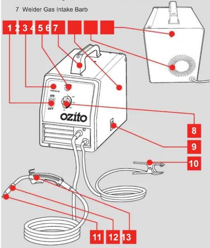
KNOW YOUR PRODUCT
MIG WELDER
1 On/Off Switch 8 Output Voltage Control Dial
2 Overload Protection LED 9 Side Cover Release Lever
3 Wire Feed Speed 10 Earth Clamp
4 Carry Handle 11 Torch Tip
5 Side Cover 12 Shroud
6 Internal Cooling Fan 13 MIG Torch
7 Welder Gas Intake Barb
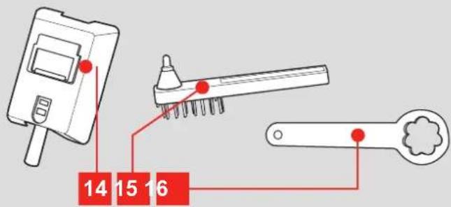
ACCESSORIES
14 Welding Mask 16 Terminal Spanner
15 Chipping Hammer / Wire Brush
ONLINE MANUAL
Scan this QR Code with your mobile device to take you to the online manual.

SETUP & PREPARATION
1. TERMINAL CONFIGURATION

WARNING: ENSURE THE TOOL IS SWITCHED OFF AND DISCONNECTED FROM THE POWER SUPPLY BEFORE PERFORMING ANY OF THE FOLLOWING STEPS.
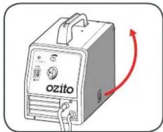
Setting the Welding Current for Gasless or Gas Shielded
1 Open the side cover by raising the side cover release lever.
natural_image
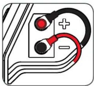
Illustration of a ozito industrial control unit with a red curved arrow indicating rotation (no text or symbols on the device itself)Gasless Welding Mode Gas Shielded Welding Mode
2 Connect the positive welding cable (red) to the negative terminal and the negative welding cable (black) to the positive terminal.
2 Connect the positive welding cable (red) to the positive terminal and the negative welding cable (black) to the negative terminal.
natural_image
Pure electrical circuit lines without any symbols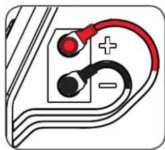
natural_image
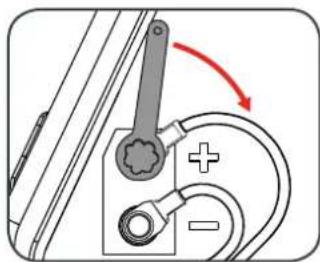
Diagram of a car charging plug with red and black wires, no text or symbols present3 Ensure that the terminals are secure by tightening the terminal knobs using the terminal spanner.
natural_image
Mechanical diagram showing a lever mechanism with a red curved arrow indicating rotation (no text or symbols)
WARNING: TERMINAL KNOBS MUST BE SECURELY TIGHTENED PRIOR TO OPERATION. LOOSE OR INCORRECT FASTENING MAY CAUSE THE CONNECTION TO OVERHEAT OR BURN.
Attaching the Shielding Gas Hose and Regulator
When using a shielding gas with the MIG welder, you will require additional hoses and gauges. These additional accessories are available at your local gas supplier and are not included with your MIG welder.
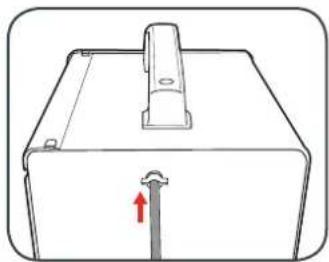
1 Connect the hose to the welder gas intake barb and secure in place with the appropriate hose clamp.
natural_image
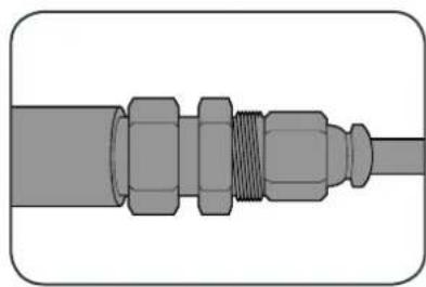
Line drawing of a mechanical component with a red arrow indicating a force or direction (no text or symbols)2 When using a shielding gas with a disposable argon gas bottle, you may need to purchase a hose reducing adaptor from your gas supplier.
natural_image
Pure diagram of a mechanical connector or fitting without any text, numbers, or symbols- Check with your local gas supplier for their recommendations of the required gas mixture and flow rate for your MIG welder.
- Check all of the connections to the gauges and the shielding gas bottle for leaks prior to commencing to weld.
IG THE WELDING WIRE COIL
The MIG welder is supplied with a 0.2kg coil of 0.8mm gasless welding wire. Welding wire up to 5kg can be fitted to this welder using the 5kg coil adaptor.
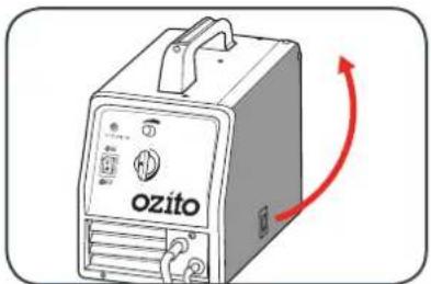
1 Open the side cover by lifting the side cover release lever.
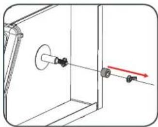
2 Remove the wing nut by rotating anti-clockwise and remove the drive washer.
natural_image
Technical diagram showing a mechanical assembly with a pulley and two bolts, no text or symbols present3 If a 5kg wire coil is to be fitted, slide the coil adaptor onto the wire drive shaft.
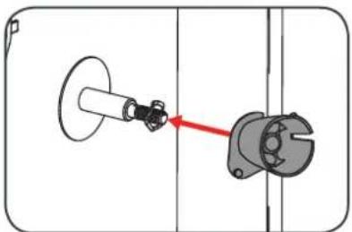
natural_image
Mechanical assembly diagram showing a shaft and housing with a red arrow indicating direction (no text or symbols)Note: This step can be skipped if a smaller wire coil is to be fitted.
4 Slide the welding wire coil onto the shaft.
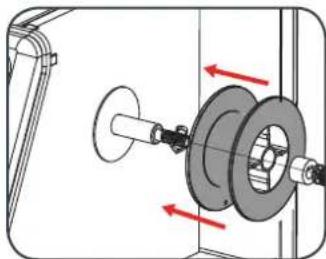
natural_image
Mechanical assembly diagram showing a pulley and wheel mechanism with red directional arrows indicating motion (no text or labels)5 Align the drive washer lug with the slot in the drive shaft and secure with the wing nut but do not over tighten.
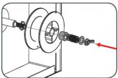
natural_image
Mechanical assembly diagram showing a pulley and shaft assembly with a red arrow indicating direction (no text or symbols)Note: Over tightening of the wing nut will restrict the wire feed rate and can cause damage to the wire feed motor or irregular welding.
OPERATION
4. WIRE DRIVE ROLLER SIZE 5. FEEDING

CAUTION: IT IS CRITICAL THAT YOU CHOOSE THE CORRECT WIRE DRIVE ROLLER SIZE.
There are two different size rollers included with the MIG welder, a roller to suit gasless flux-cored welding wire (0.8 - 0.9mm) and a general purpose wire (0.6 - 0.8mm).
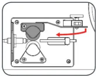
1 Release the pressure of the pressure roller by loosening the adjustable pressure screw anti-clockwise.
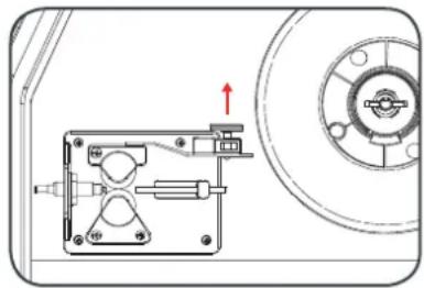
natural_image
Technical diagram of a mechanical assembly with a circular component and directional arrow (no text or symbols)2 Push the pressure arm down and swing away from the welder to release the pressure roller.
natural_image
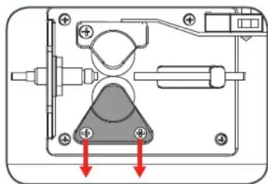
Mechanical assembly diagram showing a lever mechanism with no visible text or symbols3 Remove the wire drive roller bracket by removing the 2 fastening screws.
natural_image
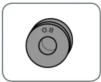
Mechanical component diagram showing a handle assembly with red arrows indicating downward motion (no text or symbols)4 Lift the wire drive roller off the shaft and inspect it to confirm the wire groove size stamped on either face. Always ensure the wire drive roller size you require is facing outward when assembled.
natural_image
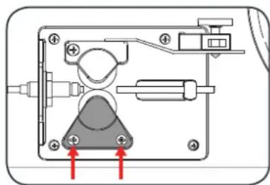
Simple 3D illustration of a circular mechanical part with concentric rings and a central hole, no text or symbols present.5 Secure the wire drive roller by fitting the drive roller bracket and fastening with the 2 screws.
natural_image
Mechanical assembly diagram showing a clamping mechanism with two red arrows pointing to specific components (no text or labels present)Note: Do not over tighten the 2 drive roller bracket screws as this could damage the MIG welder.
THE WELDING WIRE

WARNING: THE POWER SUPPLY FOR THIS PRODUCT SHOULD BE PROTECTED BY A RESIDUAL CURRENT DEVICE (RATED AT 30MA OR LESS). A RESIDUAL CURRENT DEVICE REDUCES THE RISK OF ELECTRIC SHOCK.

WARNING: ENSURE THAT YOU DO NOT MAKE CONTACT WITH THE EARTH CLAMP AT ANY STAGE WHEN FEEDING THE WELDING WIRE THROUGH THE MIG TORCH. THE ELECTRODE WIRE WILL BE AT WELDING VOLTAGE WHILST IT IS BEING FED THROUGH THE WELDER. KEEP THE MIG TORCH AWAY FROM YOUR EYES AND FACE.
Ensure the welding wire is free from any kinks and bends by removing any damaged wire. When cutting the wire, ensure it is not cut at an angle. It is recommended you lightly file the flat end of the wire prior to feeding.
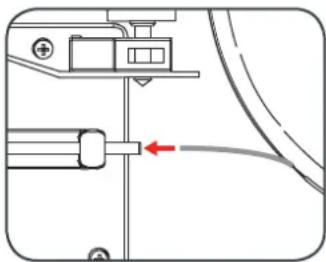
1 With the pressure arm swung away from the drive roller, feed the welding wire into the flexible inner tube.
natural_image
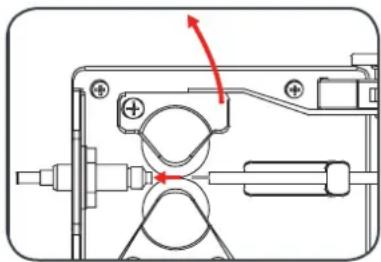
Pure mechanical diagram showing a lever mechanism with a red arrow indicating direction (no text or symbols)2 Lift up the pressure arm and pass the wire through the inlet guide ensuring the wire is positioned in the groove of the drive roller.
natural_image
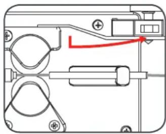
Technical diagram of a mechanical assembly with no visible text or symbols3 Push the pressure arm downward and swing towards the welder into the adjustable pressure screw.
natural_image
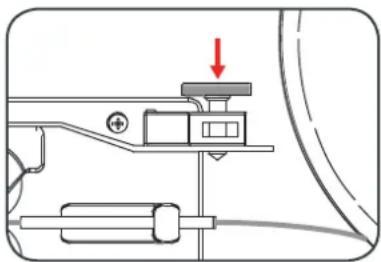
Pure mechanical component diagram without any text, numbers, or symbols4 Tighten the adjustable pressure screw so that the screw is about half way down.
natural_image
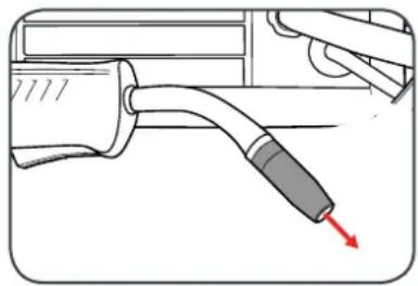
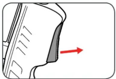
Mechanical assembly diagram showing a lever mechanism with a red arrow indicating direction (no text or symbols present)5 Remove the shroud and then unscrew the torch tip from the MIG torch by turning anticlockwise.
natural_image
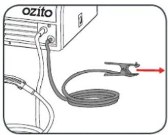
Diagram of a mechanical device with a curved pipe and a red arrow pointing to it (no text or symbols present)6 Ensure the earth clamp is away from the MIG torch and the welder housing
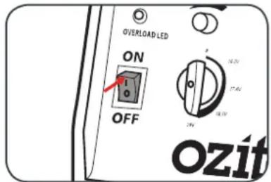
7 Plug the power chord into a power socket and switch the on/off switch into the on position.
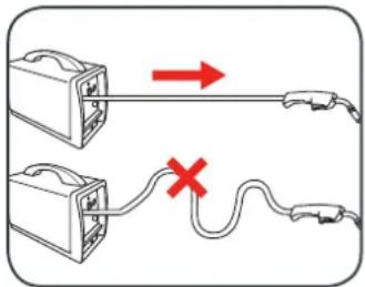
8 Ensure the MIG torch lead is straight and depress the MIG torch trigger switch to feed the wire through.
9 Once the wire protrudes out of the end of the MIG torch release the trigger and switch the on/off switch to the off position.
natural_image
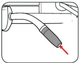
Diagram of a mechanical component with a red arrow indicating direction (no text or symbols present)10 Fit the appropriate torch tip by rotating clockwise and then refit the shroud. Cut any excess welding wire by leaving approx. 10mm protruding from the end of the torch.
natural_image
Diagram of a pipe fitting with a red arrow pointing to a component (no text or symbols present)6. CONTROLS
Adjusting the Wire Speed
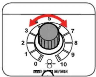
The wire speed controls the rate at which the wire is feed through the MIG torch and to your workpiece.
1 To increase the wire speed, rotate the wire feed speed dial clockwise.
2 To decrease the wire speed, rotate the wire feed speed dial anti-clockwise.
Output Voltage Control Dial
The output voltage control dial sets the voltage level of the welding terminals.
1 Rotate the output voltage control dial to select 1 of 5 settings.
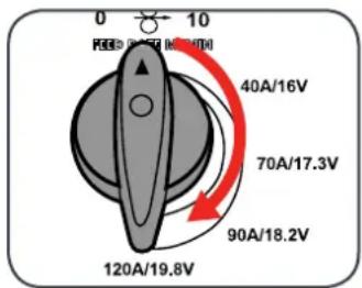

CAUTION: THE OUTPUT VOLTAGE CONTROL DIAL MUST NOT BE CHANGED DURING THE WELDING OPERATING AS THIS CAN DAMAGE INTERNAL COMPONENTS OF THE MIG WELDER.
Overload Protection LED
The MIG welder features a self re-setting thermostat that helps protect the internal components of the MIG welder.
The overload protection LED will illuminate and welding current will stop once the duty cycle of the power source has been exceeded. If the overload
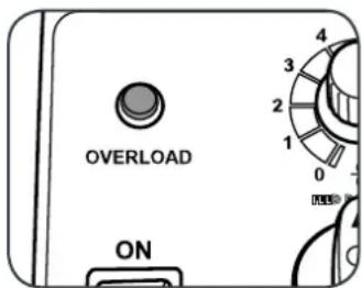
protection LED illuminates, wait for it to turn off before returning to welding operation.
7. MIG WELDING
Preparation
Before welding ensure that:
- You have read and understand the safety section of this manual.
- There is sufficient ventilation, particularly at the front and rear of the unit.
- You have an adequate fire-fighting devices on hand.
- You wear adequate protective gear while operating the MIG welder.

ENSURE ALL OIL, PETROL AND FLAMMABLE
CONTAINERS HAVE BEEN REMOVED FROM WELDING AREA.
Welding
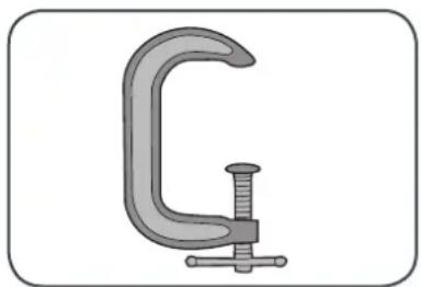
1 Ensure that your work piece is securely mounted and is cleaned and prepared ready for welding.
natural_image
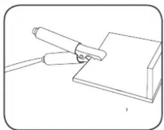
Illustration of a C-shaped clamp or clamping device with a central screw and base (no text or symbols)2 Attach the earth clamp to the workpiece so that there is a good electrical connection.
natural_image
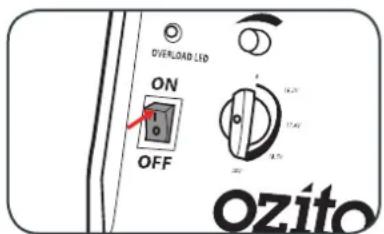
Simple line drawing of a hand using a tool to press or install a component on a base (no text or symbols)3 Switch the MIG welder on and position the welding mask in front of your eyes.
4 Position the tip roughly 8mm from the workpiece at an angle or 20^ from vertical in the direction of movement.
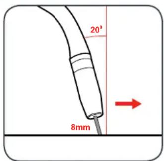
Note: Cutting the wire about 10mm long and holding the torch so the wire touches the workpiece is a good way to obtain this distance.
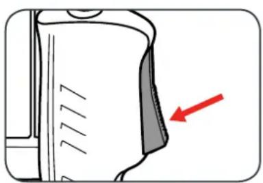
5 Squeeze the MIG torch trigger to start the weld and once completed release the trigger.
natural_image
Diagram of a device component with a red arrow pointing to a specific area (no text or symbols present)8. WELDING PROPERTIES
There are a range of welding movements used in MIG welding. Generally some form of zig-zag motion is used to ensure the arc acts against both sheets to be welded. Below are some details that may help with the welding process.
Travel Speed
The torch should be moved along at a smooth speed that will give the size of run required. At the same time, the wire is fed downwards to keep the correct welding distance at all times. Excessive travel speeds lead to poor fusion and lack of penetration. While too slow a rate of travel may damage the workpiece and can lead to burning a hole through the material.
Electricity
The electricity flows through the wire and will not leave the wire unless it is near an earthed object.
Electricity always finds the fastest path to the earth. When the earth cable clamp is connected to the metal work piece a direct earth connection is created back to the welder. When the wire touches or is near the earthed work piece when the trigger is squeezed, electricity flows through the wire, the metal work piece and then through the earth cable straight back to the welder.
Earth Clamp
Prior to connecting the earth clamp it may be necessary to clean the surface of the work piece using the metal brush. Attach the earth clamp firmly to the work piece ensuring there is good metal to metal contact. Clamp it where it will not be in the way. This clamp provides an earth connection back to the welder.
Welding Wire
There are many variables that you will need to take into account when choosing your welding wire size and type. Below are some of the things you need to take into account when choosing the welding wire:
- Thickness of the material to be welded
• Position and type of welding joint
• Maximum welding capacity of your welder
• How much penetration will be required for strength
• Type of bead desired for the weld - Whether you are using a shielding gas or not
• Type of material to be welded
WELD SETTINGS CHART
| Flux Core Arc Welding Material Thickness | ||||||||
| Material Being Welded | Suggested Shielding Gas | FCAW Wire Diameter | Suggested Settings | 1.2mm 1.5mm 2.0mm 3.0mm 6.0mm | ||||
| Steel | NO GAS Required | 0.8 | Current (A) | 40 | 40 | 70 | 90 | 120 |
| Wire Speed | 3~4 | 4~5 | 5~6 | 6~7 | 8~9 | |||
| 0.9 | Current (A) | 40 | 40 | 70 | 90 | 120 | ||
| Wire Speed | 3~4 | 4~5 | 5~6 | 6~7 | 8~9 | |||
| MIG Welding Material Thickness | |||||||||
| Material Being Welded | Suggested Shielding Gas | Solid Wire Diameter | Suggested Settings | 1.2mm | 1.0mm | 1.5mm | 2.0mm | 3.0mm | |
| Steel | 75% Argon +25% CO ^2 6-8L / MIN | 0.6 | Current (A) | 40 | 40 | 70 | 70 | ||
| Wire Speed | 7~8 7 | 5~8 9~ | 9.5 9.5~ | 10 | |||||
| 75% Argon +25% CO ^2 8-10L / MIN | 0.8 | Current (A) | 40 | 40 | 70 | 70 | 90 | 120 | |
| Wire Speed | 4~5 | 5~6 | 6~7 | 7~8 | 8~9 | 9~10 | |||
The above chart is only intended to show general guidelines for different wire sizes and for different thicknesses of material. The settings should only be used at the beginning of a weld and must be adjusted after stopping and carefully inspecting the weld. Proper welding takes good technique and practice.
ELECTRICAL SAFETY

WARNING! When using mains-powered tools, basic safety precautions, including the following, should always be followed to reduce risk of fire, electric shock, personal injury and material damage.
Read the whole manual carefully and make sure you know how to switch the tool off in an emergency, before operating the tool.
Save these instructions and other documents supplied with this tool for future reference.
The electric motor has been designed for 230V and 240V only. Always check that the power supply corresponds to the voltage on the rating plate.
Note: The supply of 230V and 240V on Ozito tools are interchangeable for Australia and New Zealand.
If the supply cord is damaged, it must be replaced by an electrician or a power tool repairer in order to avoid a hazard.
Using an Extension Lead
Always use an approved extension lead suitable for the power input of this tool. Before use, inspect the extension lead for signs of damage, wear and ageing. Replace the extension lead if damaged or defective. When using an extension lead on a reel, always unwind the lead completely. Use of an extension lead not suitable for the power input of the tool or which is damaged or defective may result in a risk of fire and electric shock.
The power supply for this product should be protected by a residual current device (rated at 30mA or less). A residual current device reduces the risk of electric shock.
GENERAL POWER TOOL SAFETY WARNINGS

WARNING! Read all safety warnings and all instructions. Failure to follow the warnings and instructions may result in electric shock, fire and/or serious injury.
Save all warnings and instructions for future reference. The term "power tool" in the warnings refers to your mains-operated (corded) power tool or battery-operated (cordless) power tool.
- Keep work areas clean. Cluttered work areas and benches can cause accidents.
- Consider work area environment. Do not expose your equipment to high humidity or rain. Do not use your equipment in damp or wet conditions. Keep the work area well lit. Do not use your tool where there is a risk of causing fire or explosion, e.g. in the presence of flammable liquids and gases.
- Keep children away. Do not allow children, visitors or animals to come near the work area or to touch the equipment or accessories.
- Dress appropriately. Wear the appropriate protective clothing. Wear a protective hair covering to keep long hair out of the way.
- Guard against electric shock. Prevent body contact with earthed or grounded surfaces. Electrical safety can be further improved by using a high sensitivity (30 mA / 30 mS) residual current device (RCD).
- Do not overreach. Keep proper footing and balance at all times.
- Stay alert. Watch what you are doing. Use common sense. Do not operate the equipment when tired.
- Secure work piece. If required, use clamps or a vice to hold the work piece.
- Extension leads. Before use inspect the extension leads and replace if damaged. When using the equipment outdoors, only use extension leads intended for outdoor use and marked accordingly.
- Use appropriate equipment. Only use the equipment as outlined within this instruction manual. Do not force the equipment to the job of heavier duty equipment. The equipment will do the job better and safer at the rate for which it was intended. Do not force the equipment.
WARNING! The use of any accessory or attachment, or performance of any operation with this equipment other than those recommended in this instruction manual may present a risk of personal injury.
- Check for damaged parts. Before use carefully check the equipment and power lead for damage. Check for misalignment and seizure of moving parts, breakage of parts, damage to guards and switches and any other conditions that may affect its operation. Ensure the equipment will operate properly and perform its intended function. Do not use the equipment if any parts are damaged or defective. Do not use the equipment if the switch does not turn it on and off. Have any damaged or defective parts repaired or replaced by an electrician or a power tool repairer. Never attempt any repairs yourself
- Unplug the equipment. Unplug the equipment when it is not in use, before changing any parts, accessories or attachments and before servicing.
- Do not abuse the cord. Never carry the equipment by its cord or pull it to disconnect from the socket. Keep the cord away from heat, oil and sharp edges.
- Store equipment. When not in use, equipment should be stored in a dry, locked up or high place, out of reach of children.
- Maintain mains equipment with care. Keep the equipment clean and in good condition for better and safer performance. Follow the instructions for maintenance and changing accessories. Keep handles and switches dry, clean and free from oil and grease.
- Have your tool repaired by an electrician or a power tool repairer. This power tool complies with relevant safety requirements. To avoid danger, electrical equipment must only be repaired by qualified technicians using original spare parts; otherwise this may result in considerable danger to the user.
- Users. This equipment is not intended for use by young children or infirmed persons without supervision. Young children should be supervised to ensure that they do not play with this equipment.
- Replacement of the supply cord. If the supply cord is damaged, it must be replaced by an electrician or a power tool repairer in order to avoid a hazard.
MIG WELDER SAFETY WARNINGS
• Under no circumstances should the housing of the welder be opened.
• Always protect your eyes and face with a welding mask.
- Wear appropriate protective clothing such as a welding apron and sleeved gloves etc.
- Avoid exposing skin as UV rays are produced by the arc.
- Screen off the work place to protect others working nearby from UV rays.
- Welding materials with contaminated surfaces may generate toxic fumes. Ensure the surface is clean before welding. Avoid operating on materials cleaned with chlorinated solvents or near such solvents.
- Do not weld metal equipment that holds/contains flammable materials, gases or liquid combustibles.
- Zinc-plated or galvanized material should not be welded as the fumes created are highly toxic.
- Do not use the welder in damp or wet conditions.
- Do not use cables with worn insulation or loose connections.
- Disconnect from the power supply before replacing electrodes.
- Avoid direct contact with the welding circuit.
- Do not use the welder to defrost piping.
- Ensure the welder is placed on a level surface to prevent overturning.
- Provide adequate ventilation or a means for removal of the welding fumes produced (forced circulation using a blower or fan).
Fumes
Toxic gases are given off during the ARC welding process, which may collect in the welding area if the ventilation is poor. Be alert at all times to the possibility of fume build-up. In small or confined areas use a fume extractor.
Glare
The electric arc generated by the arc process gives direct heat and ultraviolet radiation. It is essential that the eyes of the operator and bystanders are protected from the glare during welding.
ALWAYS USE A FACESHIELD OR WELDING HELMET FITTED WITH THE CORRECT GLASS FILTER.
Heat
It is desirable that welding gloves are worn whilst welding. They will protect the hands from ultra-violet radiation and direct heat of the arc.
Dress
In addition to face shield, welding gloves and overalls, other types of protective clothing should be worn when welding. Additional protective clothing such as a leather apron, sock protectors and a hat will all assist in reducing any injuries due to heat, sparks and slag produced during welding.
OVERALLS should also be worn. They should be of type designed to be buttoned at the wrists and the neck.

WARNING: THERE ARE EXTREMELY DANGEROUS VOLTAGE AND POWER LEVELS PRESENT INSIDE THIS PRODUCT. DO NOT ATTEMPT TO OPEN OR REPAIR UNLESS YOU ARE A QUALIFIED ELECTRICAL TRADES PERSON.
Disconnect the welding power source from the mains supply voltage before disassembling. Welding equipment should be regularly checked by a qualified electrical trades person to ensure that:
- The main earth wire of the electrical installation is intact.
- The power point for the welding power source is effectively earthed and of adequate current rating.
- Plugs and cord extension sockets are correctly wired.
- Flexible cord is of the 3-core tough rubber or plastic sheathed type of adequate rating, correctly connected and in good condition.
- Welding terminals are shrouded to prevent inadvertent contact or short circuit.
- The frame of the welding power source is effectively earthed.
- Welding leads and electrode holder are in good condition.
- The welding power source is clean internally, especially from metal filing, slag, and loose material. If any parts are damaged for any reason, replacement is recommended.
- Prior to operation, use the terminal spanner to securely tighten the terminal knobs.
Cleaning the Drive Rolls
Clean the grooves in the drive rolls frequently. This can be done by using a small wire brush. Also wipe off, or clean the grooves on the upper drive roll. After cleaning, tighten the drive roll retaining screws.

CAUTION: DO NOT USE COMPRESSED AIR TO CLEAN THE WELDING POWER SOURCE. COMPRESSED AIR CAN FORCE METAL PARTICLES TO LODGE BETWEEN LIVE ELECTRICAL PARTS AND EARTHED METAL PARTS WITHIN THE WELDING POWER SOURCE. THIS MAY RESULT IN ARCING BETWEEN THE PARTS AND THEIR EVENTUAL FAILURE.
Note: Ozito Industries will not be responsible for any damage or injuries caused by the repair of the tool by an unauthorised person or by mishandling of the tool.
TROUBLESHOOTING
| PROBLEM | CAUSE | REMEDY |
| GENERAL OPERATION | ||
| No Power | Power supply | Test supply with another product, avoid using extension leads. |
| Circuit breaker tripped | Check the rating of the circuit breaker on the supply and other appliances connected to the circuit.The welder is a high power device and it is recommended that is be the only appliance on the circuit to ensure it has enough power to operate. | |
| Welder feeding incorrectly | Wire roller wheel slipping | Increase the pressure on the pressure roller by rotating the adjustable pressure screw in a clockwise direction |
| Wire roller is applying too much pressure to the wire | Decrease the pressure on the pressure roller by rotating the adjustable pressure screw in an anti-clockwise direction | |
| Welder cuts out | Thermal overload active | The thermal overload light on the front panel will be on and the welder will not operate until cooled down and the light goes out. This is normal in heavy welding, allow the welder to cool down. |
CARING FOR THE ENVIRONMENT

Power tools that are no longer usable should not be disposed of with household waste but in an environmentally friendly way. Please recycle where facilities exist. Check with your local council authority for recycling advice.

Recycling packaging reduces the need for landfill and raw materials. Reuse of recycled material decreases pollution in the environment. Please recycle packaging where facilities exist. Check with your local council authority for recycling advice.
IMPORTANT INFORMATIONMAIN
Thermal Overload
IF YOUR WELDER OVERHEATS AND THE THERMAL OVERLOAD PROTECTION ENGAGES DO NOT TURN YOUR WELDER OFF AS THE FAN WILL ASSIST IN REDUCING THE COOLING TIME.
All Welders have a feature called a duty cycle.
Duty cycle on a welder refers to the time in which the welder operates during normal welding.
A welder can only weld for a certain continuous period of time before it requires to cool down.
If the internal components of the welder should become hot the welder could overheat. If the welder overheats the Thermal Overload Protection feature will automatically shut down the welder.
THIS CAN OCCUR IN HEAVY USE AND DOES NOT INDICATE A FAULT.
The Welder will cease to weld and the Thermal Overload LED light will turn on. This LED indication light is just to inform you that your welder is becoming too hot and requires to cool down to protect the internal components of the welder. Do Not turn your welder Off as the welder has an internal cooling fan and this will assist your welder to cool down quicker. Reducing the cooling time will enable you to get back to your welding job quicker.
Depending on how many Amps or how heavy the welding you are doing the cooling time may take up to 10 Minutes for your welder to cool down so you can return to your welding job.
DESCRIPTION OF SYMBOLS
| V | Volts | Hz | Hertz | |
| ~ | Alternating current | W | Watts | |
| m/min | Revolutions or reciprocation per minute | A | Amperes | |
| U1 | Rated AV input voltage (with tolerance ± 10% ) | X | load duration rate | |
| IImax | Rated maximum input current | I1eff | Maximum effective input current | |
| Uo | Non-load voltage | U2 | On-load voltage | |
| Vmax | Max. wire feeding speed | IP | Protection class | |
| A/Von- | Electric current adjustment range, and the relevant load voltage | Used in the environment which has high risk of electric shock | ||
 | Symbol of single-phase AV power and rated frequency |  | MAG welding | |
| [7BY6] | Do not operate in the rain | 1  | Single-phase transformer - Rectifier | |
 | Read operatoris manual |  | Warning | |
 | Double insulated |  | Regulator compliance mark | |
SPARE PARTS
Welding torch assembly SPMWR135-04
On/off switch SPMWR135-12
Wire drive roller 0.6-0.8mm SPMWR135-56
Pressure roller SPMWR135-59
Wire drive roller 0.8-.09mm SPMWR135-92
Spare parts can be ordered from the Special Orders Desk at your local Bunnings Warehouse.
For further information, or any parts not listed here, visit www.ozito.com.au or contact Ozito Customer Service:
Australia 1800 069 486
New Zealand 0508 069 486
E-mail: enquires@ozito.com.au
- WARRANTY
- YEAR REPLACEMENT WARRANTY
- WARNING
- KNOW YOUR PRODUCT
- MIG WELDER
- ACCESSORIES
- SETUP & PREPARATION
- TERMINAL CONFIGURATION
- Gasless Welding Mode Gas Shielded Welding Mode
- Attaching the Shielding Gas Hose and Regulator
- IG THE WELDING WIRE COIL
- OPERATION
- WIRE DRIVE ROLLER SIZE 5. FEEDING
- CAUTION: IT IS CRITICAL THAT YOU CHOOSE THE CORRECT WIRE DRIVE ROLLER SIZE.
- THE WELDING WIRE
- CONTROLS
- Adjusting the Wire Speed
- Output Voltage Control Dial
- Overload Protection LED
- MIG WELDING
- Preparation
- Welding
- WELDING PROPERTIES
- Travel Speed
- Electricity
- Earth Clamp
- Welding Wire
- ELECTRICAL SAFETY
- Using an Extension Lead
- GENERAL POWER TOOL SAFETY WARNINGS
- MIG WELDER SAFETY WARNINGS
- Fumes
- Glare
- Heat
- Dress
- Cleaning the Drive Rolls
- CARING FOR THE ENVIRONMENT
- IMPORTANT INFORMATIONMAIN
- Thermal Overload
- IF YOUR WELDER OVERHEATS AND THE THERMAL OVERLOAD PROTECTION ENGAGES DO NOT TURN YOUR WELDER OFF AS THE FAN WILL ASSIST IN REDUCING THE COOLING TIME.
- SPARE PARTS
Brand : Ozito
Model : MWR-135
Category : Welding machine