PFFP-65E - Pump Ozito - Free user manual and instructions
Find the device manual for free PFFP-65E Ozito in PDF.


| Product Type | Water Pump |
| Model | PFFP-65E |
| Brand | Ozito |
| Power Rating | 650 W |
| Voltage | 230 V ~ 50 Hz |
| Max Flow Rate | 6500 L/h |
| Max Head | 8 m |
| Max Immersion Depth | 7 m |
| Outlet Diameter | 1.5" (38 mm) |
| Cable Length | 10 m |
| Dimensions (L x W x H) | 250 x 150 x 200 mm |
| Weight | 5 kg |
| Material | Cast Iron / Aluminum |
| Protection Rating | IPX8 |
| Thermal Protection | Yes, automatic |
| Maintenance | Clean inlet filter regularly; check seals |
| Spare Parts Availability | Impeller, seal, float switch available |
| Intended Use | Drainage, garden watering, flood control |
Frequently Asked Questions - PFFP-65E Ozito
User questions about PFFP-65E Ozito
0 question about this device. Answer the ones you know or ask your own.
Ask a new question about this device
Download the instructions for your Pump in PDF format for free! Find your manual PFFP-65E - Ozito and take your electronic device back in hand. On this page are published all the documents necessary for the use of your device. PFFP-65E by Ozito.
USER MANUAL PFFP-65E Ozito
Engine Type: 4 Stroke, air cooled
Fuel Type: Unleaded petrol
Fuel Tank Capacity: 3.3L
Engine Capacity: 208cc
Max. Flow Rate: 11,500l/h
Max. Head: 70m
Max. Lift: 7m
Suction Inlet: 40mm (1½")
Discharge Outlet: 2 x 25.4mm (1"), 1 x 40mm (1½")
Weight: 29kg
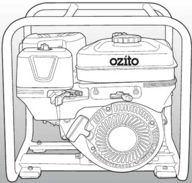
natural_image
Line drawing of a portable electricity generator with visible components and no text or symbolsSTANDARD EQUIPMENT
Petrol Pump
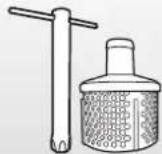
Spark Plug Wrench & Filter
5M Suction Hose
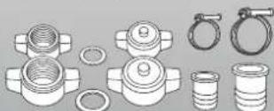
Fasteners & Adaptors
ozito.com.au
1
YEAR WARRANTY
PFFP-65E
WARRANTY
IN ORDER TO MAKE A CLAIM UNDER THIS WARRANTY YOU MUST RETURN THE PRODUCT TO YOUR NEAREST BUNNINGS WAREHOUSE WITH YOUR BUNNINGS REGISTER RECEIPT. PRIOR TO RETURNING YOUR PRODUCT FOR WARRANTY PLEASE TELEPHONE OUR CUSTOMER SERVICE HELPLINE:
Australia 1800 069 486
New Zealand 0508 069 486
TO ENSURE A SPEEDY RESPONSE PLEASE HAVE THE MODEL NUMBER AND DATE OF PURCHASE AVAILABLE. A CUSTOMER SERVICE REPRESENTATIVE WILL TAKE YOUR CALL AND ANSWER ANY QUESTIONS YOU MAY HAVE RELATING TO THE WARRANTY POLICY OR PROCEDURE.
The benefits provided under this warranty are in addition to other rights and remedies which are available to you at law.
Our goods come with guarantees that cannot be excluded at law. You are entitled to a replacement or refund for a major failure and for compensation for any other reasonably foreseeable loss or damage. You are also entitled to have the goods repaired or replaced if the goods fail to be of acceptable quality and the failure does not amount to a major failure.
Generally you will be responsible for all costs associated with a claim under this warranty, however, where you have suffered any additional direct loss as a result of a defective product you may be able to claim such expenses by contacting our customer service helpline above.
1 YEAR WARRANTY
Your product is guaranteed for a period of 12 months from the original date of purchase and is intended for DIY (Do It Yourself) use only. If a product is defective it will be repaired in accordance with the terms of this warranty. Warranty excludes consumable parts, for example: o-rings, bearing, seals, gaskets and adaptors.
WARNING
The following actions will result in the warranty being void.
- If the tool has been operated on a supply voltage other than that specified on the tool.
- If the tool shows signs of damage or defects caused by or resulting from abuse, accidents or alterations.
- Failure to perform maintenance as set out within the instruction manual.
• If the tool is disassembled or tampered with in any way.
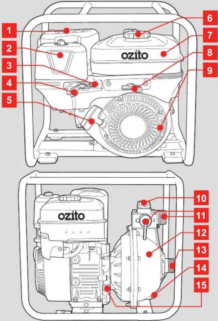
KNOW YOUR PRODUCT SETUP &
-
Exhaust
-
Fuel Cap
-
Discharge Outlet
-
Air Filter
-
Fuel Tank
-
Pump Housing
-
Choke Lever
-
Throttle Lever
13.SuctionInlet
-
Fuel Lever
-
Motor Housing
14.DrainScrew
-
Recoil Starter
-
Priming Cap
-
Oil Fill Plug
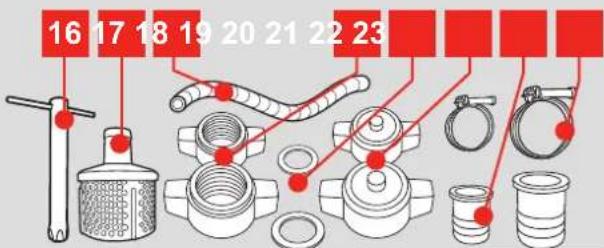
ACCESSORIES
- Spark Plug Wrench
20.O-rings
17.Filter
21.OutletCaps
- 5m Suction Hose
22.HoseAdaptors
19.Collars
23.HoseClamps
ONLINE MANUAL
Scan this QR Code with your mobile device to take you to the online manual.

PREPARATION
1. CONNECTING THE INLET

WARNING! ENSURE THE ENGINE IS SHUT OFF BEFORE PERFORMING ANY OF THE FOLLOWING ASSEMBLY.
Removing the Protection Covers
The pump inlet and outlets have been fitted with a protection cover for transportation. These will need to be removed before connecting any pipes.
Connecting the Suction Inlet
The inlet allows for a 40mm (1½") supply line to be connected and is capable of a maximum suction height of 7m.
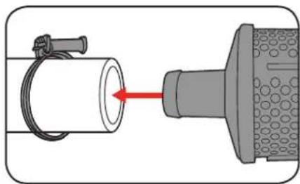
- Place the filter assembly into the intake end of the 5m suction hose and secure with a hose clamp tightly.
natural_image
Diagram showing a pipe connection with a valve and hose, no text or symbols present- Insert a hose adaptor and an o-ring into one of the collars and fasten to the outlet side of the 5m suction hose using a hose clamp.
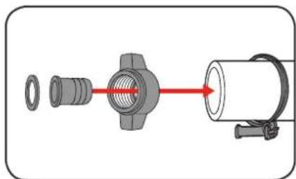
natural_image
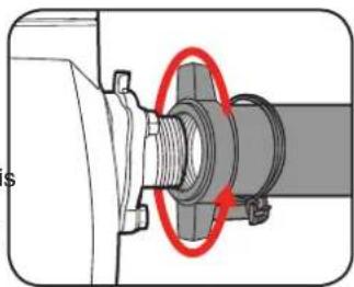
Diagram of a mechanical assembly showing a valve, connector, and housing (no text or symbols)- Screw the hose adaptor and collar tightly onto the pumps suction inlet in a clockwise direction to secure in place.
Note: Teflon tape (not supplied) is recommended on threads to ensure a water tight seal and prevent any leakage.
natural_image
Mechanical assembly diagram showing a bolted joint with a red circle highlighting a specific component (no text or symbols present)
CAUTION: THE INPUT HOSE OR PIPE SHOULD BE LOW ENOUGH IN THE WATER TO ENSURE THAT IF THE WATER LEVEL FALLS, THE PUMP WILL NOT RUN DRY. ENSURE THAT THIS IS CHECKED WHEN IN OPERATION.

CAUTION: AVOID POSITIONING THE INLET PIPE HIGHER THAN THE PUMP, AS THIS WOULD DELAY THE ESCAPE OF AIR BUBBLES FROM THE INLET PIPE.
2. CONNECTING THE OUTLET
Connecting the Discharge Outlet
The outlet allows for a 25.4mm (1") and 40mm (1½") pipe to be connected and is capable of a maximum head of 70m.
The pump has 3 outlets (2x 25.4mm and 1x 40mm), which allows for multiple outlets to be used to pump water simultaneously, however this will result in lower pressure and flow rate.

CAUTION: ALL CONNECTIONS MUST BE AIR TIGHT, FAILURE TO DO SO MAY RESULT IN AN AIR LEAK WHICH CAN PREVENT THE PUMP FROM PRIMING.
- Insertahose adaptor and an o-ring into one of the collars.
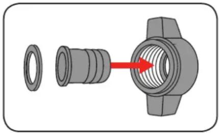
natural_image
Diagram showing a mechanical component with a red arrow indicating direction, no text or symbols present- Screw the hose adaptor and collar tightly onto one of the pump outlets in a clockwise direction to secure in place.
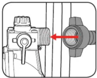
natural_image
Technical diagram of a mechanical device with a red arrow pointing to a threaded component (no text or symbols present)Note: Teflon tape (not supplied) is recommended on threads to ensure a water tight seal and prevent any leakage.
- Repeat this process to fit multiple outlets. Ensure unused outlets are fitted with the supplied outlet caps to stop water from expelling out of the discharge outlets.
NOTE: TO USE THE PUMP IN PERMANENT INSTALLATIONS WITH RIGID PIPES, INSTALL A NON-RETURN VALVE TO AVOID THE FLUID BEING RE-CIRCULATED ONCE THE PUMP HAS STOPPED.
3. INSTALLATION

CAUTION: ALWAYS CARRY OR LIFT THE PUMP BY THE FRAME TO AVOID DAMAGING THE UNIT.
Before starting, perform a few simple checks:
- Ensure the pump is mounted to a rigid base or ground.
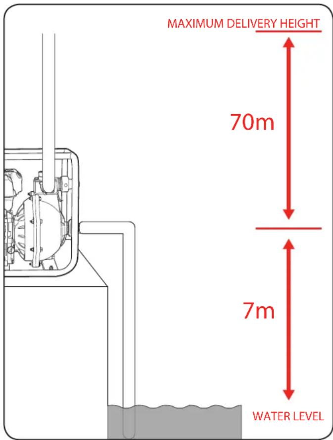
- Ensure the distance from the surface of the water to the pump inlet does not exceed 7m.
- Ensure the distance from the pump to the highest point that you wish to deliver the water does not exceed 70 metres.

CAUTION: THIS PRODUCT IS INTENDED FOR PUMPING WATER IN A HOME DOMESTIC APPLICATION. DO NOT USE IT FOR CORROSIVE, ABRASIVE, EXPLOSIVE OR DANGEROUS LIQUIDS.

WARNING! ENSURE THE OUTLET FOR THIS PUMP, INCLUDING ANY HOSES OR PIPES ARE NOT RESTRICTED OR OBSTRUCTED IN ANY WAY. TAPS, VALVES AND ANY TYPE OF TRIGGER NOZZLE MUST NEVER BE USED WITH THIS PUMP. FAILURE TO FOLLOW THESE INSTRUCTIONS MAY RESULT IN PUMP FAILURE OR SERIOUS INJURY.
OPERATION
Priming the pump prepares the motor for safe operation.

CAUTION. DO NOT RUN THE PUMP DRY, THIS MAY RESULT IN DAMAGE TO THE PUMP.
-
Ensure unused outlets are fitted with the supplied outlet caps to stop water from expelling out of the discharge outlets.
-
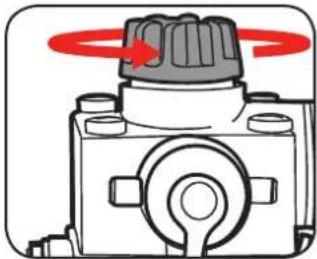
Unscrew the priming cap by turning in an anti-clockwise direction.
natural_image
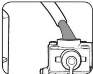
Diagram of a mechanical component with a knob and rotating arrow (no text or symbols)- Using a hose, fill the pump by pouring water into the priming hole. Ensure that the pump and suction line are full.
natural_image
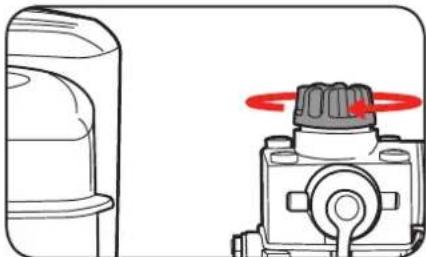
Mechanical component diagram showing a lever and housing assembly (no text or symbols)- Fit the priming cap back on and ensure it is secure.
natural_image
Technical illustration of a mechanical component with a rotating knob (no text or symbols)5. FUEL & OIL
Adding Fuel

WARNING! BE SURE TO STOP THE ENGINE BEFORE REFUELLING. DO NOT SMOKE WHILE REFUELLING.
Only use unleaded 91 RON (Research Octane Number) petrol. Purchase fuel in quantities that can be used every 30 days to prevent gum or foaming inside the container and/or fuel tank.
- Remove the fuel cap by rotating anti-clockwise.
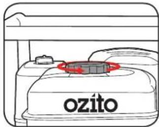
- Fill the fuel tank with the unleaded petrol. Fuel tank capacity 3.3 litres

natural_image
Line drawing of a printer with the brand name 'ozito' on its cover (no additional text or symbols)- Place the fuel cap back on and clean up any spillage.

WARNING! DO NOT OVER FILL THE FUEL TANK.
Adding Oil
After the first 25 hours of use the engine oil requires to be replaced, and then every 50 hours after that. It is recommended that SAE-10W-30 (multi viscosity) oils are used at temperatures from 5 to 35°C and synthetic oils 5W-30 (multi viscosity) is used for temperatures -5 to 5°C.
- Remove the oil fill plug from the side of the engine. Clean the dip stick and re-insert without screwing down.
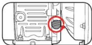
natural_image
Diagram of a device interior with a highlighted circular region and cable (no text or symbols)- Removethe dipstick and ensure the oil lays between the min and max marks.
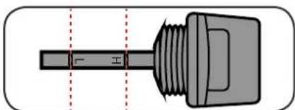
natural_image
Technical diagram of a mechanical component with threaded shaft and flange, shown without any text or symbols- If oil needs to be added simply pour oil in until the level reaches the max level of the oil gauge. Oil tank capacity 0.6 litre
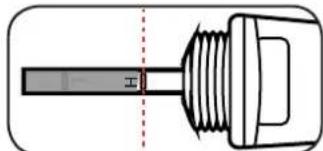
natural_image
Pure technical diagram of a mechanical component with no text or symbols- Ensure dipstick is securely tighten after oil has been topped up.
6. PRE-OPERATION INSPECTION
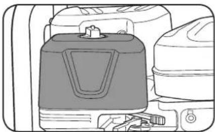
Air Filter Starting the Engine
The air filter must always be in perfect working order, to prevent debris and dust from being sucked into the engine thus reducing the efficiency and life of the machine.
- Ensure the filter is free from any debris.
natural_image
Illustration of a gas cylinder with attached fuel tank (no text or symbols)- If necessary clean or replace the filter by following the steps outlined in the maintenance section of this manual.
Spark Plugs
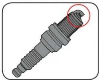
Use only the spark plugs that are recommended for this petrol pump: Champion RC12YC.
Note: Using a spark plug other than that specified could lead to serious engine damage.
- Make sure the electrode is clean and the air gap is correct (refer to the specs of the spark plug manufacture).
natural_image
3D rendered image of a mechanical screw with a highlighted section (no text or symbols)- To remove and install the spark plug refer to the maintenance section of this manual.
7. STARTING & STOPPING ENGINE
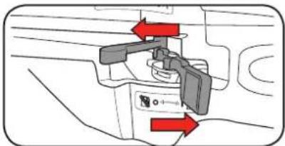
- Move the choke to the left (closed position) and the fuel lever to the right (open position).
natural_image
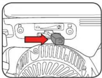
Diagram of a mechanical device with red directional arrows indicating movement or force (no text or symbols present)- Move the throttle lever to the right (fast position).
natural_image
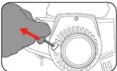
Mechanical assembly diagram showing a gear and lever mechanism with a red arrow indicating direction (no text or symbols)- Grip the recoil starter and slowly pull until resistance is felt, then pull the recoil starter rapidly. Allow the rope to rewind slowly and if necessary, repeat this procedure until the engine starts.
natural_image
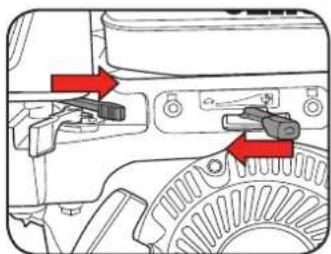
Illustration of a hand adjusting a mechanical component with a red arrow indicating rotation (no text or symbols present)- Once started move the choke lever to the right (open position) and the throttle lever to the left (slow position) and allow to idle for 3 minutes.
natural_image
Mechanical assembly diagram showing a lever mechanism with red arrows indicating direction (no text or symbols present)Stopping the Engine
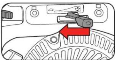
- Decrease the speed of the engine by moving the throttle to the left 🍴 and allow to idle for 10-20 seconds.
natural_image
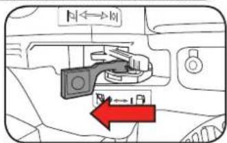
Mechanical component diagram showing a lever mechanism with a red arrow pointing to a specific part (no text or symbols present)- Move the fuel lever to the left (closed position).
Note: Allow the engine to cool down before moving or storing the pump.
8. ADJUSTING THROTTLE
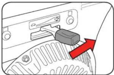
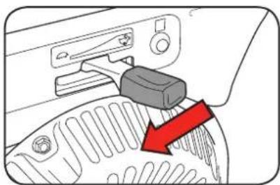
The throttle is used to regulate the rotational speed of the engine, which also controls the water flow out of the discharge outlet.
- To increase the speed of the engine and water flow, move the throttle lever left towards the "indicator."
natural_image
Diagram of a car interior showing a switch and gear mechanism with a red arrow indicating direction (no text or symbols present)- To decrease the speed of the engine and water flow, move the throttle lever right towards the " indicator.
natural_image
Diagram of a car interior showing a switch and gear mechanism with a red arrow pointing to the gear (no text or symbols present)9. MAINTENANCE
Storing the Pump
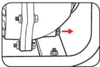
Before storing the pump, it is recommended to empty the pump body of any water.
Turn the drain screw anti-clockwise and remove from the pump body to allow excess water to drain out.
Ensure that the drain screw is fitted once all water has drained out.
natural_image
Mechanical assembly diagram showing a bracket with bolts and a red arrow indicating direction (no text or symbols)Replacing the Air Filter
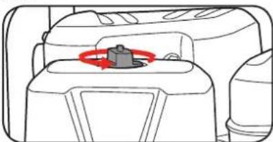
- Unscrew and remove the air filter wing nut and washer.
natural_image
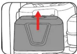
Diagram of a vehicle interior showing a highlighted component with red motion arrow (no text or symbols)- Remove the cover and the air filter. Check that the filter is intact and clean, if not rinse with water and allow to dry or replace the filter.
natural_image
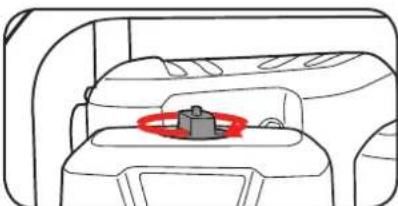
Diagram of a container with a red arrow indicating upward movement (no text or symbols)- Insert the filter and secure with the filter cover and nut.
natural_image
Diagram of a vehicle interior with a highlighted seat area (no text or symbols)Replacing the Spark Plug
-
Remove the spark plug lead.
-
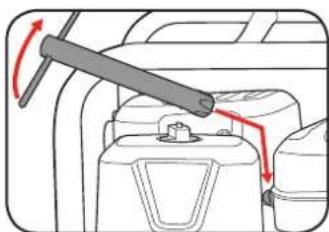
Remove the spark plug using the spark plug wrench supplied by turning anti-clockwise.
natural_image
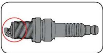
Diagram of a vehicle's fuel compartment with red arrows indicating rotation direction (no text or labels)- Clean the electrode with a metal brush and remove any carbon build-up or replace the spark plug.
natural_image
3D rendering of a spark plug with threaded shaft and mounting base (no text or symbols)- Refit the spark plug using the spark plug wrench and press the spark plug lead back on.
Recommended Check & Maintenance Chart
| Item\Time | Every operation / daily | After 20 hours or 1 month | After 50 hours or 3 months | After 100 hours or yearly |
| Inspect and tighten all nuts and bolts | ◎ | |||
| Air Filter | (Frequency depends on pump location. i.e. High dust environment every 10 Hrs) | |||
| Fuel Tank | ◎ | |||
| Fuel Tank Nozzle | ● | |||
| Fuel lines | ◎(check for leaks) | ◎(change if neccesary) | ||
| Spark Plug | ◎ | ● | ||
| Adjust inlet and exhaust valves | ◎(required after first 20 hours / 1 month of use) | ◎ * | ||
| Remove carbon in combustion chamber | ◎ * | |||
- Check
- Change
- Clean * To be performed by qualified service centre
TROUBLESHOOTING
| Problem Possible Cause Solution | ||
| Unit runs but delivers little or no water | Leak in suction hose or pipingClogged suction filterWater level above pump intakePump not primedWater level more than maximum liftEngine speed too low | Tighten suction hoses and use thread sealer.Clear debris from suction filterLower suction hose into waterFill pump with water before trying to primeMove pump closer to water level and increase discharge line length if necessaryIncrease throttle |
| Unit will not start No fuel | Fuel valve in “off” positionOil level too lowLow quality or deteriorated, old fuelDirty muffler, exhaustChoke adjusted incorrectlyAir-filter cloggedFuel evaporation in carburettor (vapour lock) due to high temperaturesSpark plug is wet or the spark plug electrode is dirty, placed inadequately or is faulty | Fill engine fuel tank. Refer to engine operating instructionsTurn fuel valve to “on” positionFill with correct oilUse only fresh 91 octane unleaded fuel.Check and cleanMove choke lever to “CLOSED” unless engine is warm. Refer to engine operating instructionsCheck, clean or replace filter as requiredWait 10 to 20 minutes then retry the starting procedureRefer to the maintenance section on how to remove and inspect |
| Unit starts but runs and performs poorly | Air-filter cloggedChoke is still engagedEngine or carburettor difficulties | Check, clean or replace filter as requiredReturn the choke to the open positionContact Ozito customer service |
MAINTENANCE
Make sure to shut off the engine, allow the engine to cool before performing maintenance procedures.
Use a moist cloth to wipe down the pump housing. Allow to dry thoroughly before storing in a dry location that is protected from bad weather conditions.
Note: Ozito will not be responsible for any damage or injuries caused by repair of the pump by an unauthorised person or by mishandling.
DISPOSAL AND RECYCLING

Power tools that are no longer usable should not be disposed of with household waste but in an environmentally friendly way. Please recycle where facilities exist. Check with your local council authority for recycling advice.

Recycling packaging reduces the need for landfill and raw materials. Reuse of recycled material decreases pollution in the environment. Please recycle packaging where facilities exist. Check with your local council authority for recycling advice.

GENERAL POWER TOOL SAFETY WARNINGS

WARNING! Read all safety warnings and all instructions. Failure to follow the warnings and
instructions may result in electric shock, fire and/or serious injury.
Save these instructions
- Work area safety
a. Keep work area clean and well lit. Cluttered or dark areas invite accidents.
b. Do not operate pumps in explosive atmospheres, such as in the presence of flammable liquids, gases or dust. Pumps create sparks which may ignite the dust or fumes.
c. Keep children and bystanders away while operating a pump. Distractions can cause you to lose control. - Personal safety
a. Stay alert, watch what you are doing and use common sense when operating a pump. Do not use a pump while you are tired or under the influence of drugs, alcohol or medication. A moment of inattention while operating a pump may result in serious personal injury.
b. Avoid accidental starting. Carrying pump with your finger on the recoil starter invites accidents. - Pump use and care
a. Store Idle pump out reach of children and other untrained persons. Pumps are dangerous in the hands of untrained users.
b. Always shut off the engine, allow the engine to cool and remove spark plug before making any adjustments, changing accessories, or storing pumps. Such preventive safety measures reduce the risk of starting the pump accidentally.
c. Maintain pumps. Check for misalignment or binding of moving parts, breakage of parts and any other condition that may affect the pumps operation. If damaged, have the pump repaired before use. Many accidents are caused by poorly maintained pumps.
d. Use the pump, and accessories etc., in accordance with these instructions and in the manner intended for the particular type of pump, taking into account the working conditions and the work to be performed. Use of the pump for operations different from intended could result in a hazardous situation.
4. Service
a. Have your pump serviced by a qualified repair person using only identical replacement parts. This will ensure that the safety of the pump is maintained.

ADDITIONAL SAFETY WARNINGS FOR PUMPS

WARNING! This product is intended for pumping water in a Home Domestic application. Do not use it for corrosive, abrasive, explosive or dangerous liquids. Fluids other than water will damage the water pump and/or create a fire hazard. Failure to follow all instructions listed below may result in electric shock, fire and/or serious injury.
WARNING! This product is not suitable for use with drinking (potable) water.
This appliance is not intended for use by person (including children) with reduced physical, sensory or mental capabilities, or lack of experience and knowledge, unless they have been given supervision or instruction concerning use of the appliance by a person responsible for their safety.
Children should be supervised to ensure that they do not play with the appliance.
- Ensure the water pump is switched off when installing.
- Do not install or operate the water pump in an explosive environment or near flammable material.
- Do not operate the water pump without liquid.
- Do not run the water pump dry.
- Never refuel while engine is running or hot. Fuel spilled on a hot engine could result in a fire or explosion.
- Use caution when handling petrol. Refuel in well-ventilated area. Do not overfill fuel tank and do not spill fuel. Make sure tank cap is closed properly. Petrol is extremely flammable and is explosive under certain conditions.
-
Never run the engine in an enclosed or confined area. Exhaust contains poisonous carbon monoxide gas; exposure may cause loss of consciousness and may lead to death.
-
Do not use to pump flammable or explosive liquids such as gasoline, fuel oil, kerosene, solvents or thinners. Pump should only be used with liquids compatible with pump component materials. Failure to follow to this warning can result in serious personal injury, death and/or property damage.
- Pump must be located on a solid level surface. Pump could tip or fall causing serious injury.
- Do not hold or suspend pump by means of a discharge pipe. Pipe could break or come loose.
- Be careful not to touch the muffler while it is hot. To avoid severe burns or fire hazards, let the engine cool before transporting or storing it indoors. The muffler becomes very hot during operation and remains hot for a while after stopping the engine. Exhaust may contain chemicals that may cause cancer or reproductive harm.

WARNING! The water pump together with associated pipework operate under pressure. Do not disconnect water pump or pipework until internal pressure has been released. Failure to do this could result in personal injury and damage to property.
- Avoid inserting hands into the inlets/outlets of the water pump while it is operating.
- Before using the water pump, always inspect it visually. Do not use the pump if it is cracked and/or damaged. If the water pump is damaged, contact Ozito customer service.
• The pump must not be used when people are in the water. - Pollution of the liquid could occur due to leakage of lubricants
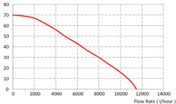
FLOW CURVE
Head Height (m)
PFFP-65E Pump Flow Curve
line
| Flow Rate (I/hour) | Value | |---|---| | 0 | 70 | | 2000 | 68 | | 4000 | 58 | | 6000 | 45 | | 8000 | 32 | | 10000 | 18 | | 12000 | 0 |ORDERING REPLACEMENT PARTS
Spare parts can be ordered from the Special Orders Desk at your local Bunnings Warehouse.
For further information, or any parts not listed here, visit www.ozito.com.au or contact Ozito Customer Service:
Australia 1800 069 486 New Zealand 0508 069 486
E-mail: enquiries@ozito.com.au
DESCRIPTION OF SYMBOLS
| V | Volts | Hz | Hertz |
| ~ | Alternating current | W | Watts |
| /min rec | Revolutions or procation per minute | no | No load speed |
| Hp | Horse power | °C | Degrees Celsius |
| cc | Cubic centimeters |  | Hot surface |
 | Fire |  | Toxic fumes |
| p/hr | Per hour |  | Pressure rating (kilopascals) |
| bar | Pressure rating |  | Litres |
| F | Insulation class |  | Polyvinyl chloride |
 | Regulator compliance mark |  | Ingress protection from water |
 | Warning |  | Read instruction manual |
- WARRANTY
- YEAR WARRANTY
- WARNING
- KNOW YOUR PRODUCT SETUP &
- ACCESSORIES
- PREPARATION
- CONNECTING THE INLET
- Removing the Protection Covers
- Connecting the Suction Inlet
- CONNECTING THE OUTLET
- Connecting the Discharge Outlet
- INSTALLATION
- Before starting, perform a few simple checks:
- OPERATION
- FUEL & OIL
- Adding Fuel
- Adding Oil
- PRE-OPERATION INSPECTION
- Air Filter Starting the Engine
- Spark Plugs
- STARTING & STOPPING ENGINE
- Stopping the Engine
- ADJUSTING THROTTLE
- MAINTENANCE
- Storing the Pump
- Replacing the Air Filter
- Replacing the Spark Plug
- MAINTENANCE
- DISPOSAL AND RECYCLING
- GENERAL POWER TOOL SAFETY WARNINGS
- ADDITIONAL SAFETY WARNINGS FOR PUMPS
- FLOW CURVE
- ORDERING REPLACEMENT PARTS
- DESCRIPTION OF SYMBOLS
Brand : Ozito
Model : PFFP-65E
Category : Pump