PTP-012A - Pump Ozito - Free user manual and instructions
Find the device manual for free PTP-012A Ozito in PDF.


| Product Type | Submersible Pump |
| Model | PTP-012A |
| Brand | Ozito |
| Power Rating | 750 W |
| Voltage | 230 V ~ 50 Hz |
| Max Flow Rate | 10,000 L/h |
| Max Head | 8 m |
| Max Particle Size | 25 mm |
| Hose Connection | 1" BSP (external thread) |
| Motor Protection | Thermal overload cut-out |
| Housing Material | Stainless steel / Engineering plastic |
| Weight | 5.2 kg |
| Cable Length | 10 m |
| Operating Temperature | 0 - 35 °C |
| Protection Class | IP68 (submersible) |
| Cleaning | Rinse with fresh water after use |
| Maintenance | Check impeller and seal regularly |
| Safety Features | Fully submersible, thermal protection, double insulation |
| Spare Parts Available | Seal kit, impeller, float switch |
| Repairability | Designed for easy part replacement; professional service recommended |
Frequently Asked Questions - PTP-012A Ozito
User questions about PTP-012A Ozito
0 question about this device. Answer the ones you know or ask your own.
Ask a new question about this device
Download the instructions for your Pump in PDF format for free! Find your manual PTP-012A - Ozito and take your electronic device back in hand. On this page are published all the documents necessary for the use of your device. PTP-012A by Ozito.
USER MANUAL PTP-012A Ozito
Max. Head: 10m approx.
Inlet/Outlet Size: 12.7mm (1/2")
Water Temp: 5°C - 45°C
Weight: 1.8kg
ozito.com.au
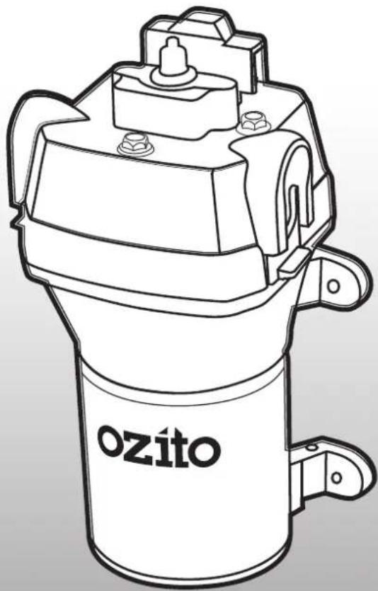
natural_image
Line drawing of a cylindrical mechanical device with no visible text or symbols on the bodyWHAT'S IN THE BOX
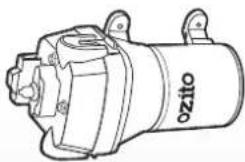
natural_image
Line drawing of a mechanical device with no visible text or symbols12V Pressure Pump
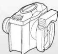
Stainless Steel Filter
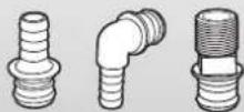
3x Inlet/Outlet Adaptors
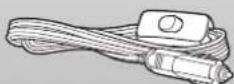
2.1m Cord with On/Off
Switch & 12V DC Plug
3
YEAR REPLACEMENT WARRANTY
PTP-012A
KNOW YOUR PRODUCT
PRESSURE PUMP
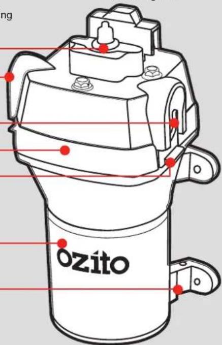
1 Pressure Switch
5 Slide Locking Clip
2 Water Outlet
6 Motor Body
3 Water Inlet
7 Mounting Feet
4 Upper Housing

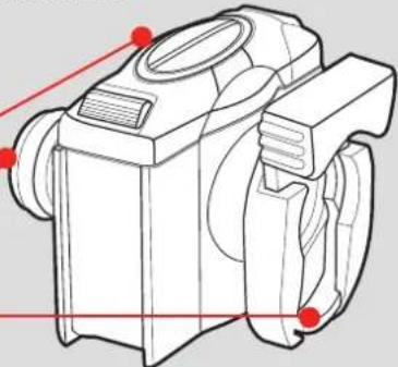
STAINLESS STEEL FILTER
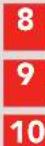
8 Filter Cap
9 Filter Outlet
10 Filter Inlet
natural_image
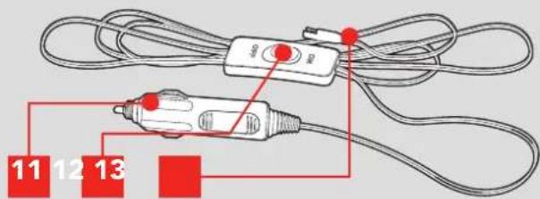
Technical line drawing of a mechanical device with red alignment markers (no text or symbols)11 12V DC Plug
13 Power Cord Connector
12 On/Off Switch
ONLINE MANUAL
Scan this QR Code with your mobile device to take you to the online manual.

SETUP & PREPARATION
1. STAINLESS STEEL FILTER

WARNING: ENSURE THE TOOL IS SWITCHED OFF AND DISCONNECTED FROM THE POWER SUPPLY BEFORE PERFORMING ANY OF THE FOLLOWING STEPS.
The pump can be used with or without the stainless steel filter. The filter should be used when the water being pumped contains contaminants.
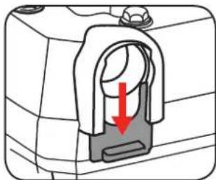
1 Push the slide locking clip on the pump inlet down and ensure the water inlet is clear.
natural_image
Diagram of a mechanical component with a red arrow indicating a downward force or direction (no text or symbols present)2 Push the filter unit firmly into the water inlet of the pump.
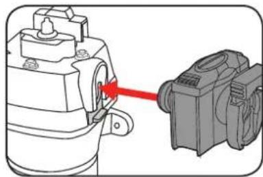
natural_image
Mechanical assembly diagram showing a motor connected to a housing via a red arrow (no text or symbols present)3 Lock the unit in place by pushing the slide locking clip back up.
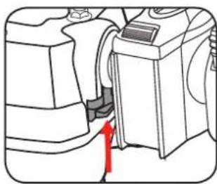
natural_image
Diagram of a mechanical device with a red arrow pointing to a component (no text or symbols present)Attaching Hose to the Water Inlet
1 Raise the slide locking clip on the inlet side of the filter.
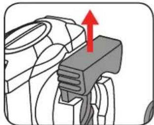
natural_image
Diagram of a tractor's wheel and gear assembly with a red upward arrow indicating motion (no text or symbols)2 Place the male hose adaptor in the inlet of the filter and secure by lowering the slide locking clip.
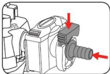
natural_image
Technical diagram of a mechanical assembly with red arrows indicating directional components (no text or labels)3 Attach a suitable hose to the male adaptor, fit hose clamps (not included) and tighten.
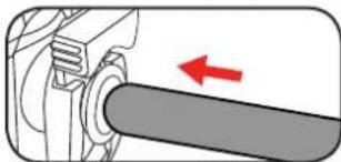
natural_image
Mechanical assembly diagram showing a shaft and housing with a red arrow indicating direction (no text or symbols)
WARNING: THE INPUT HOSE SHOULD BE LOW ENOUGH IN THE WATER TO ENSURE THAT IF THE WATER FALLS, THE PUMP WILL CONTINUE TO OPERATE CORRECTLY.
Attaching Hose to the Outlet
1 Lower the slide locking clip on the water outlet.
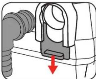
natural_image
Diagram of a mechanical component with a red arrow indicating downward motion (no text or symbols present)2 Place the male hose adaptor in the outlet and secure by lifting the slide locking clip.
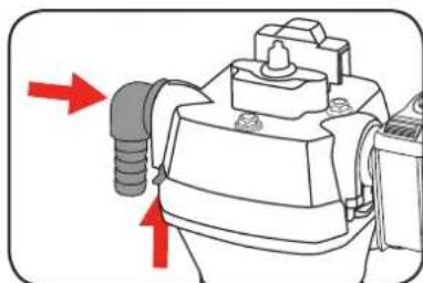
natural_image
Diagram of a mechanical device with red arrows indicating directional flow or movement (no text or symbols present)3 Attach a suitable hose to the outlet adaptor, fit hose clamps (not included) and tighten.
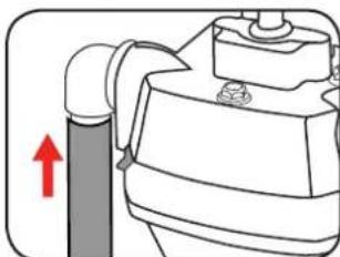
natural_image
Diagram of a mechanical device with a red upward arrow indicating motion or force (no text or symbols present)3. TURNING ON & OFF2. ATTACHING A H
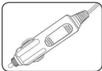
The pump comes supplied with an auxiliary cable. The 12V DC plug on the auxiliary cable enables the pump to be powered from a standard 12V power outlet found in cars, boats and some generators.
natural_image
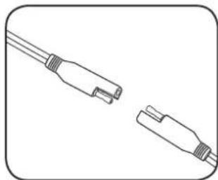
Line drawing of a handheld electronic device with ports and leads (no text or symbols)1 Attach the 12V power cable adaptor to the pump.
natural_image
Line drawing of two connected cable connectors (no text or symbols)2 Plug the 12V adaptor into a suitable power source.
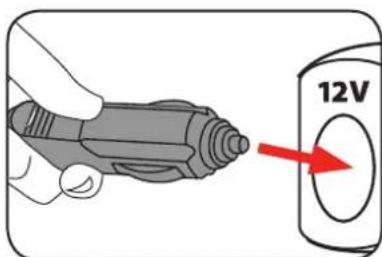

IMPORTANT! ENSURE THAT ALL ELECTRICAL WIRING IS SECURED IN PLACE WITH THE CONNECTIONS WELL AWAY FROM THE WATER.
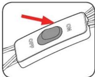
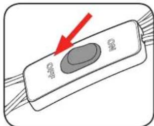
3 Switch the on/off switch into the on position.
natural_image
Illustration of a control panel with a red arrow pointing to its left side (no text or symbols present)3 To turn the pump off switch the on/off switch into the off position.
4. INSTALLATION
Installation Guide for Portable Applications
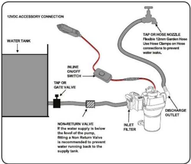
flowchart
graph TD
    A["12VDC ACCESSORY CONNECTION"] --> B["WATER TANK"]
    B --> C["TAP OR GATE VALVE"]
    C --> D["INLINE ON/OFF SWITCH"]
    D --> E["TAP OR HOSE NOZZLE Flexible 12mm Garden Hose Use Hose Clamps on Hose connections to prevent water leaks."]
    E --> F["DISCHARGE OUTLET"]
    F --> G["INLET FILTER"]
    G --> H["NON-RETURN VALVE"]
    H --> I["If the water supply is below the level of the pump, fitting a Non Return Valve is recommended to prevent water running back to the supply tank"]
Installation Guide for Permanent Applications
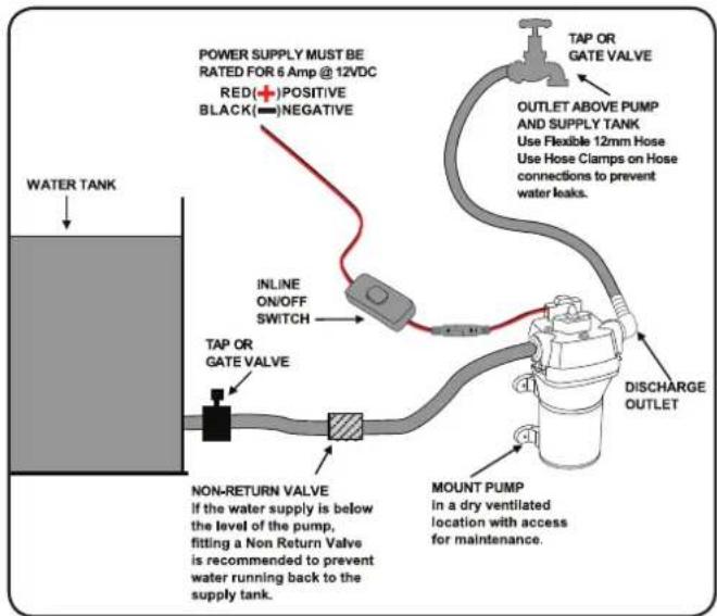
flowchart
graph TD
    A["POWER SUPPLY MUST BE RATED FOR 6 Amp @ 12VDC RED(+) POSITIVE BLACK(=) NEGATIVE"] --> B["TAP OR GATE VALVE"]
    B --> C["OUTLET ABOVE PUMP AND SUPPLY TANK Use Flexible 12mm Hose Use Hose Clamps on Hose connections to prevent water leaks."]
    C --> D["DISCHARGE OUTLET"]
    D --> E["MOUNT PUMP in a dry ventilated location with access for maintenance."]
    F["WATER TANK"] --> G["TAP OR GATE VALVE"]
    G --> H["INLINE ON/OFF SWITCH"]
    H --> I["NON-RETURN VALVE If the water supply is below the level of the pump, fitting a Non Return Valve is recommended to prevent water running back to the supply tank."]
    I --> J["SHOWNING SWITCH"]
    J --> K["SHOWNING SWITCH"]

WARNING: THE INPUT HOSE SHOULD BE LOW ENOUGH IN THE WATER TO ENSURE THAT IF THE WATER FALLS, THE PUMP WILL CONTINUE TO OPERATE CORRECTLY. ENSURE THAT THIS IS CHECKED WHEN IN OPERATION.
NOTE: A leaking hose or pipe will draw in air and therefore not draw in any water.
Note: When not using the supplied auxiliary cable (ie. when setting up a fixed installation), it is recommended that you use a 10 Amp fuse and a 12V/10 Amp power supply.
Mounting
The following should be considered to achieve optimum pump operation.
- The pump can be mounted at the same level or below the water supply. It may be positioned above the water supply if need, as it is capable of a 1.8m vertical prime. Horizontal inlet will allow priming to 9m.
- The pump can be mounted in any position. If mounting the pump vertically, the pump head should be in the down position for optimum performance.
- The Mounting Feet are intended to isolate the pump from mounting surface; over tightening, flattening, or use of oversized screws will reduce the ability to isolate vibration and noise.
Positioning the Hose
Position the input hose so that it rises from the water drawing source to the pump. Avoid positioning the input hose higher than the pump, as this would delay the escape of air bubbles from the input hose and impede the priming process.
We recommended at least 0.3m of 12.7mm I/D flexible hose to the inlet and outlet connections. Use hose clamps on hose connections to prevent water leaks.
Note: If the water supply is below the level of the pump, fitting a Non Return Valve is recommended to prevent water running back to the water supply.
MAINTENANCE TROUBLESHOOT
Cleaning the Filter Unit

WARNING: ENSURE THE TOOL IS SWITCHED OFF AND DISCONNECTED FROM THE POWER SUPPLY BEFORE PERFORMING ANY OF THE FOLLOWING STEPS.
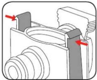
1 Press in the locking tabs on each side of the filter to release the filter cap.
natural_image
Mechanical assembly diagram showing a threaded component with red arrows indicating force or movement (no text or symbols present)2 Remove the filter cap and clean debris from the filter using a light brush and warm soapy water.
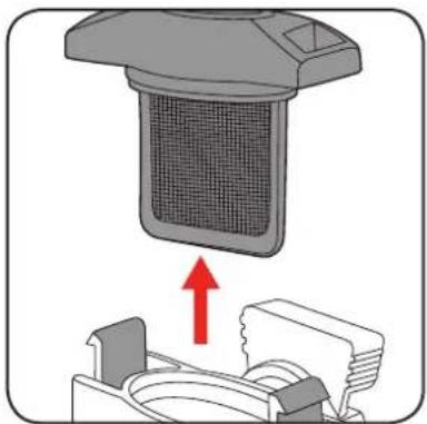
natural_image
Diagram showing a device with a mesh cover and a red upward arrow, no text or symbols present3 Once clean, push the filter cap back onto the filter tabs until it clicks into place.
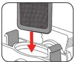
natural_image
Diagram showing a device with a mesh screen and a red arrow pointing to a component (no text or symbols present)Maintenance
Regularly check the pump to be sure that the filter base and impeller are not clogged with debris. Follow the instruction in this manual to clean the filter if clogged.
Storage
The pump itself is not affected by freezing temperatures. However, if the pump is embedded in ice or surrounded by ice, it cannot be used. Never turn the pump on if it is embedded in or surrounded by ice
NG
| Symptom Possible Cause | Cure |
| Pump not working | Blown fuse Replace fuse in 12V DC Plug |
| Reduced Flow | Blockage Clean debris from around impeller and clean the filter. |
| Water line clogged | |
| Low battery voltage | |
| Kinked water hose | |
| No water pumped | Wire connections |
| Float switch failure. (if connected). | |
| Pump won't shut off. | Something under the float (if connected) |
| Stuck float (if connected). | |
| IMPORTANT. Switch mounted too low |
DESCRIPTION OF SYMBOLS
| V | Volts | W | Watts |
| DC | Direct current | mA | Milliamperes |
| Litres per hourL/H | IP | Ingress protection from water | |
| Regulator compliance mark | PVC | Polyvinyl chloride | |
| Warning | Read instruction manual | ||
GENERAL PUMP SAFETY WARNINGS

WARNING! Read all safety warnings and all instructions. Failure to follow the warnings and instructions may result in electric shock, fire and/or serious injury.
Save these instructions
- Work area
a. Keep work area clean and well lit. Cluttered or dark areas invite accidents.
b. Do not operate pumps in explosive atmospheres, such as in the presence of flammable liquids, gases or dust. Pumps create sparks which may ignite the dust or fumes.
c. Keep children and bystanders away while operating a pump. Distractions can cause you to lose control.
- Electrical safety
When using 12 Volt equipment, basic safety precautions, including the following, should always be followed to reduce risk of fire, electric shock, personal injury and material damage.
a. Do not abuse the cord. Never use the cord for carrying, pulling or unplugging the pump. Keep cord away from heat, oil, sharp edges or moving parts. Damaged or entangled cords increase the risk of electric shock.
b. The electric motor has been designed for 12V only. Always check that the power supply corresponds to the voltage on the rating plate.
- Personal safety
a. Stay alert, watch what you are doing and use common sense when operating a pump. Do not use a pump while you are tired or under the influence of drugs, alcohol or medication. A moment of inattention while operating pumps may result in serious personal injury.
b. Avoid accidental starting. Ensure the switch is in the off position before plugging in. Carrying pumps with your finger on the switch or plugging in pumps that have the switch on invites accidents.
c. Remove any adjusting key or wrench before turning the pump on. A wrench or a key left attached to a rotating part of the pump may result in personal injury.
d. Dress properly. Do not wear loose clothing or jewellery. Keep your hair, clothing and gloves away from moving parts. Loose clothes, jewellery or long hair can be caught in moving parts.
- Pump use and care
a. Disconnect the plug from the power source before making any adjustments, changing accessories, or storing pumps. Such preventive safety measures reduce the risk of starting the pump accidentally.
b. Maintain pumps. Check for misalignment or binding of moving parts, breakage of parts and any other condition that may affect the pumps operation. If damaged, have the pump repaired before use. Many accidents are caused by poorly maintained pumps.
c. Use the pump, accessories and tool bits etc., in accordance with these instructions and in the manner intended for the particular type of pump, taking into account the working conditions and the work to be performed. Use of the pump for operations different from intended could result in a hazardous situation.
- Service
a. Have your pump serviced by a qualified repair person using only identical replacement parts. This will ensure that the safety of the pump is maintained.
! PORTABLE PRESSURE PUMP SAFETY WARNINGS

CAUTION: Not intended for cleaning and other maintenance of swimming pools.

WARNING! This product is intended for pumping water in a home domestic application.
Do not use it for corrosive, abrasive, explosive or dangerous liquids. Fluids other than water will damage the water pump and/or create a fire hazard. WARNING! This product is not suitable for use with drinking (potable) water.

This appliance is not intended for use by persons (including children) with reduced physical, sensory or mental capabilities, or lack of experience and knowledge, unless they have been given supervision or instruction concerning use of the appliance by a person responsible for their safety.
Children should be supervised to ensure that they don't play with the appliance.
- Ensure the pressure pump is disconnected from mains power when installing
- Do not install or operate the water pump in an explosive environment or near flammable material.
- Do not operate the water pump without liquid.
- Do not run the water pump dry.

WARNING! The water pump together with associated pipework operate under pressure.
Do not disconnect water pump or pipework until internal pressure has been released. Failure to do this could result in personal injury and damage to property.
- Avoid inserting hands into the inlets/outlets of the water pump while it is connected to mains power.
- Before using the water pump, always inspect it visually. Do not use the pump if it is cracked and/or damaged. If the water pump is damaged, contact customer service.
Never work or perform maintenance on the pump without first making sure it has been disconnected from the mains power.
Pollution of the liquid could occur due to leakage of lubricants.

IMPORTANT: The electrical connections must always be made in a dry area. Make sure that electrical connections are protected from inundations. Protect the plug and the power cable from heat, oil or sharp edges. If damaged, the power cable must be replaced by a qualified electrician.
CARING FOR THE ENVIRONMENT

Pumps that are no longer usable should not be disposed of with household waste but in an environmentally friendly way. Please recycle where facilities exist. Check with your local council authority for recycling advice.

Recycling packaging reduces the need for landfill and raw materials. Reuse of recycled material decreases pollution in the environment. Please recycle packaging where facilities exist. Check with your local council authority for recycling advice.
SPARE PARTS
Spare parts can be ordered from the Special Orders Desk at your local Bunnings Warehouse.
For further information, or any parts not listed here, visit www.ozito.com.au or contact Ozito Customer Service:
Australia 1800 069 486
New Zealand 0508 069 486
E-mail: enquires@ozito.com.au
WARRANTY
IN ORDER TO MAKE A CLAIM UNDER THIS WARRANTY YOU MUST RETURN THE PRODUCT TO YOUR NEAREST BUNNINGS WAREHOUSE WITH YOUR BUNNINGS REGISTER RECEIPT. PRIOR TO RETURNING YOUR PRODUCT FOR WARRANTY PLEASE TELEPHONE OUR CUSTOMER SERVICE HELPLINE:
Australia 1800 069 486
New Zealand 0508 069 486
TO ENSURE A SPEEDY RESPONSE PLEASE HAVE THE MODEL NUMBER AND DATE OF PURCHASE AVAILABLE. A CUSTOMER SERVICE REPRESENTATIVE WILL TAKE YOUR CALL AND ANSWER ANY QUESTIONS YOU MAY HAVE RELATING TO THE WARRANTY POLICY OR PROCEDURE.
The benefits provided under this warranty are in addition to other rights and remedies which are available to you at law.
Our goods come with guarantees that cannot be excluded at law. You are entitled to a replacement or refund for a major failure and for compensation for any other reasonably foreseeable loss or damage. You are also entitled to have the goods repaired or replaced if the goods fail to be of acceptable quality and the failure does not amount to a major failure.
Generally you will be responsible for all costs associated with a claim under this warranty, however, where you have suffered any additional direct loss as a result of a defective product you may be able to claim such expenses by contacting our customer service helpline above.
3 YEAR REPLACEMENT WARRANTY
Your product is guaranteed for a period of 36 months from the original date of purchase. If a product is defective it will be replaced in accordance with the terms of this warranty. Warranty excludes consumable parts, for example: o-rings, bearings, seals, gaskets, drain caps, and all accessories.
WARNING
The following actions will result in the warranty being void.
- If the pump has been operated on a supply voltage other than that specified on the tool.
- If the pump shows signs of damage or defects caused by or resulting from abuse, accidents or alterations.
- Failure to perform maintenance as set out within the instruction manual.
• If the pump is disassembled or tampered with in any way.
• Professional, industrial or high frequency use.
- KNOW YOUR PRODUCT
- PRESSURE PUMP
- STAINLESS STEEL FILTER
- SETUP & PREPARATION
- STAINLESS STEEL FILTER
- Attaching Hose to the Water Inlet
- Attaching Hose to the Outlet
- TURNING ON & OFF2. ATTACHING A H
- INSTALLATION
- Mounting
- Positioning the Hose
- MAINTENANCE TROUBLESHOOT
- Cleaning the Filter Unit
- Maintenance
- Storage
- NG
- DESCRIPTION OF SYMBOLS
- GENERAL PUMP SAFETY WARNINGS
- Save these instructions
- ! PORTABLE PRESSURE PUMP SAFETY WARNINGS
- CARING FOR THE ENVIRONMENT
- SPARE PARTS
- WARRANTY
- YEAR REPLACEMENT WARRANTY
- WARNING
Brand : Ozito
Model : PTP-012A
Category : Pump