MWR-9045 - Welding machine Ozito - Free user manual and instructions
Find the device manual for free MWR-9045 Ozito in PDF.


| Product Type | MIG Welder (Gasless Flux-Cored) |
| Model | MWR-9045 |
| Brand | Ozito |
| Welding Current | 50A / 90A (switch selectable) |
| Welding Wire Size | 0.8 mm and 0.9 mm flux-cored wire |
| Duty Cycle | 60% @ 50A, 10% @ 90A |
| Insulation Class | Class I |
| Max. Wire Spool Weight | 0.4 kg |
| Weight (tool only) | 14 kg |
| Power Supply | 230V / 240V AC, 50 Hz |
| Rated Input Current | Not specified in manual (estimate 15-20A based on output) |
| Protection Class | IP21 (typical for welders, not explicitly stated) |
| Thermal Overload Protection | Yes, with LED indicator and automatic shutdown |
| Wire Feed Speed | Adjustable via knob |
| Torch Type | MIG torch with interchangeable tip (0.8/0.9 mm) |
| Earth Clamp | Included |
| Accessories Included | Welding mask, chipping hammer/wire brush, carrying strap, wire feed roller, shroud, torch tip |
| Warranty | 3-year replacement warranty |
| Operating Environment | Indoor, dry; avoid rain and high humidity |
| Duty Cycle Cooling | Internal fan, do not switch off during cooling |
Frequently Asked Questions - MWR-9045 Ozito
User questions about MWR-9045 Ozito
0 question about this device. Answer the ones you know or ask your own.
Ask a new question about this device
Download the instructions for your Welding machine in PDF format for free! Find your manual MWR-9045 - Ozito and take your electronic device back in hand. On this page are published all the documents necessary for the use of your device. MWR-9045 by Ozito.
USER MANUAL MWR-9045 Ozito
Welding Current: 50 / 90Amp
Welding Wire Size: 0.8, 0.9mm Flux-Cored Wire
Duty Cycle: 60%@50A, 10%@90A
Insulation Type: Class I
Max. Wire Spool Weight: 0.4kg
Weight (tool only): 14kg
ozito.com.au
WHAT'S IN THE BOX
MIG Welder
0.8mm Welding Wire & Welding Mask

Chipping Hammer / Wire Brush

Carrying Strap

Wire Feed Roller,
Shroud & Torch Tip
3 YEAR REPLACEMENT WARRANTY
MWR-9045
WARRANTY
IN ORDER TO MAKE A CLAIM UNDER THIS
WARRANTY YOU MUST RETURN THE PRODUCT
TO YOUR NEAREST BUNNING O WARELLION OF WITH
The benefits provided under this warranty are in addition
to other rights and remedies which are available to you at law.
Our goods come with guarantees that cannot be excluded
KNOW YOUR PRODUCT
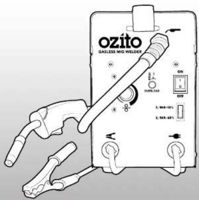
MIG WELDER
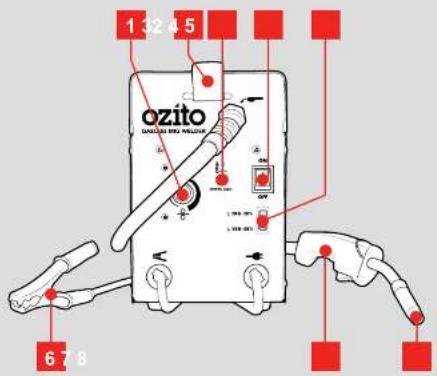
1 Wire Feed Speed 5 Current Control Switch
2 Carry Handle 6 Earth Clamp
3 Overload Protection LED 7 MIG Torch
4 On/Off Switch 8 Torch Tip
ACCESSORIES
9 Welding Mask 12 Shroud (spare)
10 Chipping Hammer / Wire 13 Torch Tip (spare)
SETUP & PREPARATION
1. WELDING MASK & CARRY STRAP
Fitting the Welding Screen
The included welding mask must be fitted with the welding screen and handle before using for welding.
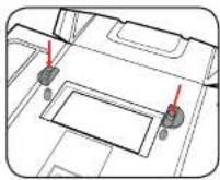
1 Insert the glass retaining pins into the holes from the outside of the mask and then fit the retaining clips from the inside. Rotate the clip to allow the glass to be inserted.
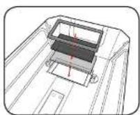
2 First insert the clear glass into the recess of the welding mask, followed by the dark safety glass and then the plastic frame. Rotate the retaining clips to lock in position.
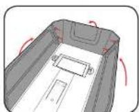
3 Bend the sides and top of the welding mask inwards and clip together at the corners.
2. FITTING THE WELDING WIRE COIL

WARNING: ENSURE THE TOOL IS SWITCHED OFF AND DISCONNECTED FROM THE POWER SUPPLY BEFORE PERFORMING ANY OF THE FOLLOWING STEPS.
The MIG welder can be fitted with 0.8mm or 0.9mm gasless welding wire. Welding wire up to 0.4kg can be fitted to this welder.
1 Open the top cover by rotating the locking knob and then lifting the panel.
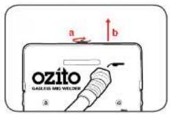
2 Remove the wing nut by rotating anti-clockwise and remove the drive washer.
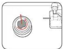
3 Slide the welding wire coil onto the shaft. Ensure the unwound end of the welding
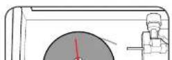
There are two sizes on the roller included with the MIG welder; one side of the roller suits 0.8mm gasless flux-cored welding wire and the other suits 0.9mm gasless flux-cored welding wire.
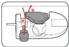
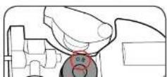
1 Rotate the locking arm up and then swing the pressure arm away from the guide roller.
2 Rotate the roller locking dial anti-clockwise and lift off.
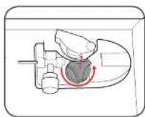
3 Lift the wire drive roller off the shaft and inspect it to confirm the wire groove size stamped on either face. Ensure the wire drive roller size you
OPERATION
5. FEEDING THE WELDING WIRE

THE WELDER IS NOT SUITABLE FOR USE

WARNING THE POWER SUPPLY FOR THIS PRODUCT SHOULD BE PROTECTED BY A RESIDUAL CURRENT DEVICE (RATED AT 30MA OR LESS). A RESIDUAL CURRENT DEVICE REDUCES THE RISK OF ELECTRIC SHOCK.

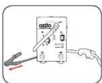
WARNING: ENSURE THAT YOU DO NOT MAKE CONTACT WITH THE EARTH CLAMP AT ANY STAGE WHEN FEEDING THE WELDING WIRE THROUGH THE MIG TORCH. THE ELECTRODE WIRE WILL BE AT WELDING VOLTAGE WHILE IT IS BEING FED THROUGH THE WELDER. KEEP THE MIG TORCH AWAY FROM YOUR EYES AND FACE.
Ensure the welding wire is free from any kinks and bends by removing any damaged wire. When cutting the wire, ensure it is not cut at an angle. It is recommended you lightly file the flat end of the wire prior to feeding.
1 With the pressure arm swung away from the drive roller, feed the welding wire into the flexible inner tube.
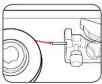
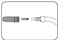
4 Remove the shroud and then unscrew the torch tip from the MIG torch by turning anti-clockwise.
6 Ensure the earth clamp is away from the MIG torch and the welder housing
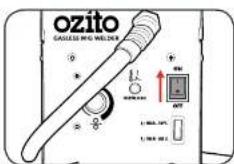
7 Plug the power cord into a power supply and switch the on/off switch into the on position.
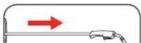
8 Ensure the MIG torch lead is straight and depress the MIG torch trigger to feed the wire
6. CONTROLS
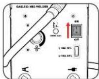
On/Off Switch
1 To switch on, press the on/off switch up into the on position.
2 To switch off, press the on/off switch down into the off position.
Output Current Control
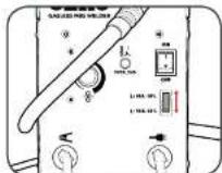
The output current switch has 2 settings: 50A and 90A.
1 Press the current switch into the desired operating setting

WARNING: THE OUTPUT VOLTAGE CONTROL DIAL MUST NOT BE CHANGED DURING THE WELDING OPERATING AS THIS CAN DAMAGE INTERNAL COMPONENTS OF THE MIG WELDER.
Adjusting the Wire Speed
7. MIG WELDING
Preparation
Before welding ensure that:
- You have read and understand the safety section of this manual.
- There is sufficient ventilation, particularly at the front and rear of the unit.
• You have an adequate fire-fighting devices on hand. - You wear adequate protective gear while operating the MIG welder, such as welding gloves and the provided face mask.

WARNING: ENSURE ALL OIL, PETROL AND FLAMMABLE CONTAINERS HAVE BEEN REMOVED FROM WELDING AREA.
Welding
1 Ensure that your work piece is securely mounted and is cleaned and prepared ready for welding.
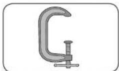
2 Attach the earth clamp to the workpiece so that there is a good electrical connection.
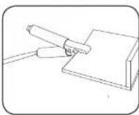
3 Switch the MIG welder

OPERATION
8. WELDING PROPERTIES
There are a range of welding movements used in MIG welding. Generally some form of zig-zag motion is used to ensure the arc acts against both sheets to be welded. Below are some details that may help with the welding process.
Travel Speed
The torch should be moved along at a smooth speed that will give the size of run required. At the same time, the wire is fed downwards to keep the correct welding distance at all times. Excessive travel speeds lead to poor fusion and lack of penetration. While too slow a rate of travel may damage the work piece and can lead to burning a hole through the material.
Electricity
The electricity flows through the wire and will not leave the wire unless it is near an earthed object.
Electricity always finds the fastest path to the earth. When the earth cable clamp is connected to the metal work piece a direct earth connection is created back to the welder. When the wire touches or is near the earthed work piece when the trigger is squeezed, electricity flows through the wire, the metal work piece and then through the earth cable straight back to the welder.
Earth Clamp
Prior to connecting the earth clamp it may be necessary to clean the surface of the work piece using the metal brush. Attach the earth clamp firmly to the work piece ensuring there is good metal to metal contact. Clamp it where it will not be in the way. This clamp provides an earth connection back to the welder.
Welding Wire
There are many variables that you will need to take into account when choosing your welding wire size and type. Below are some of the things you need to take into account when choosing the welding wire:
- Thickness of the material to be welded
- Position and type of welding joint
• Maximum welding capacity of your welder
• How much penetration will be required for strength
• Type of bead desired for the weld - Whether you are using a shielding gas or not
• Type of material to be welded
WEID CETTING CHART
TROUBLESHOOTING
| PROBLEM | CANCE | REQUENCY |
| GENERAL OPERATION | ||
| Air Power | Power supply | Test apply with other product, allowing the solar cells. |
| Circuit breakers trapped | Electrical using of the current breakers and the supply and other appliances connected to the circuit. This is a high power source and a recommended that it is the only appliance on the direct or near-in line of the smart power system. | |
| Welder feed up into water supply | Water worker has unslipped | Because the pressure on the pressure rather than moving the water above in power source in a locked oil cell. |
| Water worker applying the much convenience to the wire | Because the pressure on the pressure under the way moving the water above in power source in an electric cell. | |
| Welder cut-out | Thermal overload activity | The thermal overload is a hole or the front drain oil can be used and the vertical flow is too much as indicated by the right-hand side. This is a motorized by the drip, allowing the water above soil. |
MAINTENANCE

WARNING: THERE ARE EXTREMELY DANGEROUS VOLTAGE AND POWER LEVELS PRESENT INSIDE THIS PRODUCT. DO NOT ATTEMPT TO OPEN OR REPAIR UNLESS YOU ARE A QUALIFIED ELECTRICAL TRADES PERSON.
Disconnect the welding power source from the mains supply voltage before disassembling. Welding equipment should be regularly checked by a qualified electrical trades person to ensure that:
• The main earth wire of the electrical installation is intact.
• The power point for the welding power source is effectively earthed and of adequate current rating.
- Plugs and cord extension sockets are correctly wired.
- Flexible cord is of the 3-core tough rubber or plastic sheathed type of adequate rating, correctly connected and in good condition.
• Welding terminals are shrouded to prevent inadvertent contact or
IMPORTANT INFORMATION
DESCRIPTION OF SYMBOLS
Thermal Overload
IF YOUR WELDER OVERHEATS AND THE THERMAL OVERLOAD PROTECTION ENGAGES DO NOT TURN YOUR WELDER OFF AS THE FAN WILL ASSIST IN REDUCING THE COOLING TIME.
All Welders have a feature called a duty cycle.
Duty cycle on a welder refers to the time in which the welder operates during normal welding.
A welder can only weld for a certain continuous period of time before it requires to cool down.
If the internal components of the welder should become hot the welder could overheat. If the welder overheats the Thermal Overload Protection feature will automatically shut down the welder.
THIS CAN OCCUR IN HEAVY USE AND DOES NOT INDICATE A FAULT.
The Welder will cease to weld and the Thermal Overload LED light will turn on. This LED Indication light is just to inform you that your welder is becoming too hot and requires to cool down to protect the internal components of the welder. Do Not turn your welder Off as the welder has an internal cooling fan and this will assist your welder to cool down quicker. Reducing the cooling time will enable you to get back to your welding job quicker.
Depending on how many Amps or how heavy the welding you are doing the cooling time may take up to 10 Minutes for your welder to cool down so you can return to your welding job.
| V | Volts | Hz | Hertz |
| Altering current | W | Watts | |
| m/min | Revolutions or radionization per minute | A | Angeves |
| U1 | Rated AV input voltage (with tolerance =10%) | X | cad duration rate |
| Imax | Rated maximum input current | Ieff | Maximum effective input current |
| Uo | Non-inoded voltage | Uo | On-road voltage |
| Vmax | Max. wire feeding speed | IP | Protection class |
| A/V | electric current adjustment range, and the relevant on-road voltage | Used in the environment which has high risk of electric shock | |
| Symbol of single phase AW power and rated frequency | M/VE welding | ||
| Do not operate in the rain | Road instruction manual | ||
| Regulator compliance mark | Warning |
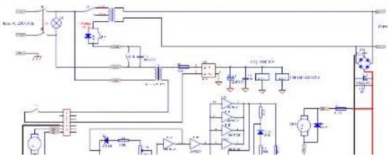
CIRCUIT DIAGRAM
ELECTRICAL SAFETY

WARNING! When using mains-powered tools, basic safety precautions, including the following rules: (1) a general safety risk of safety risks; (2) a safety risk of safety risks; (3) a safety risk of safety risks;
following, should always be followed to reduce risk of fire, electric shock, personnel injury and material damage.
and material damage
Read the whole manual carefully and make sure you know how to switch the tool off in an emergency, before waiting for the tool.
Save these instances and other cinquments supplied with this trust for future reference.
The electric motor has been designed for 230V and 240V only. Always check that the power is only
consequence to the voltage on the starting plate.
Note: The supply of 230V and 240V on Oziba tools are interchangeable for Australia and New Zealand.
If the supply cord is damaged, it must be replaced by an electrician or a power tool repairer in order to avoid a home.
Ubs on Extension Load
Using an Extension Book
Адмукция не approved scientist lead scalable for the power input of this tool. Before use, respect the
extension lead for signs of damage, wear and aging. Replace the extension lead I damaged or defective.
When using an extension lead on a reel, always untamed the lead completely. Use of an extension lead not
suitable for the power input of the xo or which is damaged or defective may result in a risk of fire and electric
37845
The power supply for this product should be protected by a residual current device rated at 30mA or less. A
excellent carney disease reduces the risk of election shock.
GENERAL POWER TOOL SAFETY WARNINGS

WARNING! Read all safety warnings and all instructions. Failure to follow the warnings and
Instructions may result in discrete shock, the shock or sensitive injury
Show an earnings and instructions for future reference. The term "power tool" in the
Warnings refers to your mains-operated (corded) power tool or battery-operated (cordless) power tool.
POWER TECH.
-
Keep work areas clean. Cluttered work area and benchse can cause accidents.
-
Consider work area environment. Do not expose your equipment to high humidity or rain. Do not use
your equipment in damp or well conditions. Keep the work area well ill. Do not use your tool where there
Is a risk of causing fire or explosion, e.g. In the presence of flammable liquids and gases.
- Keep children away. Do not allow children, visitors or animals to come near the work area or to touch
the equipment or accessories
-
Does appendate: Wear the appropriate advertisement clothing. Was a prospective hairreversing in keep
-
Dress appropriately, 17/31
-
Hand against electrode shock. However, actively and/or regulated procedure. Finland
-
Guard against electric shock. Prevent body contact with carried or grounded surfaces. Electrical
Sally can be seen to produce that a high level of activity (30 m/s, 25 m/s) is important for the medical (NCU).
-
Do not overreach. Keep proper footing and balance at all times.
-
Stay start. Watch what you are doing. Use common sense. Do not cope to be scanned when used.
-
Secure work place. If required, no clamps or uses to hold the work piece.
-
Explanar index: Fishy as important salmon leads to seepness Adamped When manihe
-
Extension leads. Before LBS inspect the extension losses and replace it damaged. When using the
- Use appropriate equipment. Only use the equipment as outlined within this instruction manual. Do not force the equipment to the job of heavier duty equipment. The equipment will do the job better and safer at the rate for which it was intended. Do not force the equipment.

WARNING!
equipment other than those recommended in this instruction manual may present a risk of personal
[NO TEXT]
- Check for damaged parts. Before use carefully check the equipment and power lead for damage.
Dr. 100, 2000; 1998; 1997; 1996; 1995; 1994; 1993; 1992; 1991; 1990; 1989; 1988; 1987; 1986; 1985; 1984; 1983; 1982; 1981; 1980; 1979; 1978; 1977; 1976; 1975; 1974; 1973; 1972; 1971; 1970; 1969; 1968; 1967; 1966; 1965; 1964; 1963; 1962; 1961; 1960; 1959; 1958; 1957; 1956; 1955; 1954; 1953; 1952; 1951; 1950; 1949; 1948; 1947; 1946; 1945; 1944; 1943; 1942; 1941; 1940; 1939; 1938; 1937; 1936; 1935; 1934; 1933; 1932; 1931; 1930; 1929; 1928; 1927; 1926; 1925; 1924; 1923; 1922; 1921; 1920; 1919; 1918; 1917; 1916; 1915; 1914; 1913; 1912; 1911; 1910; 1909; 1908; 1907; 1906; 1905; 1904; 1903; 1902; 1901;
Check for missing data, and secure the following: please call to https://doi.org/10.1034/j.jr.2018.
- And any other conditions that may effect its operation. Ensure this equipment will operate properly at
perform its functional function. Do not use the equipment if any parts are damaged or defective. Do
not use the equipment if the switch does not turn it or and off. Have any damaged or defective point
replaced or replaced by an electrician or a power tool repairer. Never attempt any repairs yourself
- Unplug the equipment. Unplug the equipment when it is not in use, before changing any parts.
accessories or attachments and before servicing
-
Do not abuse the cord. Now, came the equipment by its cord or pull it to disaligned from the market.
-
Do not abuse the cold. Never carry the equipment. By its cold or part to a cold work from the source. Keep the cold away from next, all and share edges.
-
Floor improvement: Hiway's only one, an immediate building almost every second up at high slope until
-
Store equipment
REACHING
- Maintain mains equipment with care. Keep the equipment clean and in good condition for better and
rains performance. Follow the instructions for me be seen and consider six key points. Kendelles
and switches dry, clean and fine immant and crease
-
Have your tool required by an electrician or a power tool receiver. This power tool requires with
-
Three-year-old recovered by an obstinator of a potential that repainted. The pilot and competitor will
relevant, easily required. To avoid danger, electrical equipment, etc., only be covered by qualified
Technicians using original spare parts, otherwise this may result in considerable danger to the case.
- Users. This equipment is not intended for use by young children or informed persons without supervision.
Young children should be supervised to ensure that they do not pay with this equipment.
-
Replacement of the supply cord. If the supply cord is damaged, it must be retained by an electrical
-
Replacement of the supply cord. It is supply co or a power tool required in order to avoid a hazard.
MIG WELDER SAFETY WARNINGS
• Under no circumstances should the housing of the welder be opened.
• Always protect your eyes and face with a welding mask.
- Many anthropists, protective clothing such as a combination menu and silver plate;
Methods of reducing electromagnetic disturbances
- If interference occurs when the equipment is connected to the mains power supply in a
In this notice, please contact the equipment to contact us to the mark point supply of a residential idocystin: low voltage power network, an electrogenic filter may be required.
- WHAT'S IN THE BOX
- YEAR REPLACEMENT WARRANTY
- WARRANTY
- KNOW YOUR PRODUCT
- MIG WELDER
- ACCESSORIES
- SETUP & PREPARATION
- WELDING MASK & CARRY STRAP
- Fitting the Welding Screen
- FITTING THE WELDING WIRE COIL
- OPERATION
- FEEDING THE WELDING WIRE
- CONTROLS
- On/Off Switch
- Output Current Control
- Adjusting the Wire Speed
- MIG WELDING
- Preparation
- Welding
- WELDING PROPERTIES
- Travel Speed
- Electricity
- Earth Clamp
- Welding Wire
- TROUBLESHOOTING
- MAINTENANCE
- IMPORTANT INFORMATION
- DESCRIPTION OF SYMBOLS
- Thermal Overload
- CIRCUIT DIAGRAM
- ELECTRICAL SAFETY
- GENERAL POWER TOOL SAFETY WARNINGS
- MIG WELDER SAFETY WARNINGS
Brand : Ozito
Model : MWR-9045
Category : Welding machine