
VESS A2600 - Video recorder Promise Technology - Free user manual and instructions
Find the device manual for free VESS A2600 Promise Technology in PDF.


| Product Type | NVR Storage Appliance (Video Recorder) |
| Brand | Promise Technology |
| Model | VESS A2600 |
| Form Factor | 3U, 19-inch rack-mount or desktop |
| Dimensions (H x W x D) | 45 x 46 x 140 cm |
| Weight (without drives) | 15.9 kg (35.1 lbs) |
| Weight (with drives) | 27.9 kg (61.5 lbs) |
| Power Supply | 450W single (A2600s) or 500W N+1 redundant (A2600) |
| Processor | Intel Xeon E3 Quad-core 8-thread |
| Memory | 8 GB DDR3 (expandable to 16 GB) |
| Supported Drives | 16 x 3.5-inch SATA (3 Gb/s or 6 Gb/s) |
| RAID Levels | 0, 1, 1E, 3, 5, 6, 10, 30, 50, 60 |
| Max LUNs | 256 per system, 32 per array |
| Management Interfaces | WebPAM PROe (web GUI), CLI, CLU |
| Network Ports | 4 x Gigabit Ethernet RJ-45 |
| Video Output | HDMI, VGA |
| I/O Ports | USB 2.0/3.0, RS-232, RS-422/485, Audio In/Out, Sensor/Alarm I/O (optional) |
| Hot-Swap Drives | Yes |
| Cooling | Swappable system fan module |
| Operating System | Windows Embedded Standard 7 or Linux CentOS 6.3 |
| Safety Notices | Class A product, ESD sensitive, power off before servicing |
Frequently Asked Questions - VESS A2600 Promise Technology
User questions about VESS A2600 Promise Technology
0 question about this device. Answer the ones you know or ask your own.
Ask a new question about this device
Download the instructions for your Video recorder in PDF format for free! Find your manual VESS A2600 - Promise Technology and take your electronic device back in hand. On this page are published all the documents necessary for the use of your device. VESS A2600 by Promise Technology.
USER MANUAL VESS A2600 Promise Technology
Vess A-Series NVR Storage Appliance Product Manual
Version 1.2

Warning
This is a Class A product. In a domestic environment this product may cause radio interference in which case the user may be required to take adequate measures.

Warning
The electronic components within the Vess enclosure are sensitive to damage from Electro-Static Discharge (ESD). Observe appropriate precautions at all times when handling the Vess or its subassemblies.

Warning
Turn off the power and disconnect the power cord before servicing this device.
Also included are four levels of notices:

Warning
A Warning notifies you of probable equipment damage or loss of data, or the possibility of physical injury, and how to avoid them.

Caution
A Caution informs you of possible equipment damage or loss of data and how to avoid them.

Important
An Important message calls attention to an essential step or point required to complete a task, including things often missed.

Note
A Note provides helpful information such as hints or alternative ways of doing a task.
CONTENTS
Introduction 1
Vess A-Class Series Overview 2
SYSTEM MANAGEMENT 2
SPECIFICATIONS 3
HARDWARE 4
FRONT PANEL HARDWARE 4
FRONT PANEL LEDs 6
REAR PANEL HARDWARE 10
Hardware Setup 19
UNPACKING 20
MOUNTING THE VESS CLASS A SERIES IN A RACK 21
MOUNTING A 3U ENCLOSURE IN A RACK 22
MOUNTING A 2U ENCLOSURE IN A RACK 25
INSTALLING DISK DRIVES 29
NUMBER OF DRIVES REQUIRED 29
MANAGEMENT PATH CONNECTIONS 37
CONNECT THE POWER39
POWER ON VESS A2600/A2600s 41
POWER ON VESS A2200/A2200s 44
CONNECT TO ISCSI STORAGE AREA NETWORK (SAN) 45
INSTALL RISER CARD IN VESS A2600/A2600s 47
INSTALL PCIe CARDS IN VESS A2200/A2200s 54
Managing with WebPAM PROe 58
LOGGING INTO WEBPAM PROE 58
QUICK LINKS MENU 62
USING THE WEBPAM PROE INTERFACE 63
CHOOSING A DISPLAY LANGUAGE 65
SUBSYSTEM MANAGEMENT 68
BACKGROUND ACTIVITIES 69
MANAGE BACKGROUND ACTIVITIES SETTINGS 70
MEDIA PATROL 75
MANAGING ACTIVITY SCHEDULES 76
EVENT LOGS 77
ADMINISTRATIVE TOOLS 78
RESTORE FACTORY DEFAULT SETTINGS 78
USER MANAGEMENT 79
VIEWING USER INFORMATION 79
MAKING USER SETTINGS 79
CREATING A USER 81
VIEW NETWORK SETTINGS 83
SOFTWARE MANAGEMENT 83
EMAIL SERVICE 88
PERFORMANCE MONITORING 90
CONTROLLERS 92
VIEW CONTROLLER INFORMATION 92
VIEWING CONTROLLER STATISTICS 94
CONTROLLER SETTINGS 95
ENCLOSURES 96
ENCLOSURE INFORMATION 96
ENCLOSURE TEMPERATURE SENSOR SETTINGS 97
BUZZER SETTINGS 97
PHYSICAL DRIVES 98
DISK ARRAYS AND LOGICAL DRIVES 100
LOGICAL DRIVE MANAGEMENT 102
SPARE DRIVES 103
LOGICAL DRIVE SUMMARY 104
Managing with CLU 105
USING THE CLU 107
ACCESSING ONLINE HELP 111
EXITING THE CLU 111
LOGGING OUT OF THE CLI 111
LOGGING BACK INTO THE CLI AND CLU 111
MANAGING THE SUBSYSTEM (CLU) 112
MAKING SUBSYSTEM SETTINGS (CLU) 112
RUNNING MEDIA PATROL (CLU) 113
LOCKING OR UNLOCKING THE SUBSYSTEM (CLU) 113
VIEW SUBSYSTEM DATE AND TIME (CLU) 114
MANAGING THE RAID CONTROLLERS (CLU) 115
VIEWING CONTROLLER INFORMATION (CLU) 115
MAKING CONTROLLER SETTINGS (CLU) 116
MANAGING THE ENCLOSURE (CLU) 118
VIEWING THE ENCLOSURES SUMMARY (CLU) 118
VIEWING ENCLOSURE INFORMATION (CLU) 119
MAKING ENCLOSURE SETTINGS (CLU) 119
VIEWING POWER SUPPLY STATUS (CLU) 120
To view the status of the power supplies: 120
VIEWING COOLING UNIT STATUS (CLU) 120
VIEWING TEMPERATURE SENSOR STATUS (CLU) 121
VIEWING VOLTAGE SENSOR STATUS (CLU) 121
LOCATING AN ENCLOSURE (CLU) 122
PHYSICAL DRIVE MANAGEMENT (CLU) 123
VIEWING A LIST OF PHYSICAL DRIVES (CLU) 123
MAKING GLOBAL PHYSICAL DRIVE SETTINGS (CLU) 124
VIEWING PHYSICAL DRIVE INFORMATION (CLU) 125
VIEWING PHYSICAL DRIVE STATISTICS (CLU) 126
SETTING AN ALIAS (CLU) 126
LOCATING A PHYSICAL DRIVE (CLU) 126
MANAGING DISK ARRAYS (CLU) 128
VIEWING A LIST OF DISK ARRAYS (CLU) 128
CREATING A DISK ARRAY (CLU) 129
CREATING A DISK ARRAY - AUTOMATIC (CLU) 129
CREATING A DISK ARRAY — EXPRESS (CLU) 130
CREATING A DISK ARRAY - ADVANCED (CLU) 131
DELETING A DISK ARRAY (CLU) 133
MAKING DISK ARRAY SETTINGS (CLU) 134
VIEWING DISK ARRAY INFORMATION (CLU) 135
ENABLING MEDIA PATROL, PDM, AND POWER MANAGEMENT ON A DISK ARRAY (CLU) 136
REBUILDING A DISK ARRAY (CLU) 137
RUNNING MEDIA PATROL ON A DISK ARRAY (CLU) 137
RUNNING PDM ON A DISK ARRAY (CLU) 138
RUNNING TRANSITION ON A DISK ARRAY (CLU) 139
LOCATING A DISK ARRAY (CLU) 139
MANAGING SPARE DRIVES (CLU) 140
VIEWING A LIST OF SPARE DRIVES (CLU) 140
CREATING A SPARE DRIVE (CLU) 141
MAKING SPARE DRIVE SETTINGS (CLU) 142
RUNNING SPARE CHECK (CLU) 142
DELETING A SPARE DRIVE (CLU) 143
MANAGING LOGICAL DRIVES (CLU) 144
CREATING A LOGICAL DRIVE (CLU) 144
DELETING A LOGICAL DRIVE (CLU) 146
VIEWING LOGICAL DRIVE INFORMATION (CLU) 147
VIEWING LOGICAL DRIVE STATISTICS (CLU) 147
VIEWING THE LOGICAL DRIVE CHECK TABLE (CLU) 148
MAKING LOGICAL DRIVE SETTINGS (CLU) 148
INITIALIZING A LOGICAL DRIVE (CLU) 149
RUNNING REDUNDANCY CHECK (CLU) 150
LOCATING A LOGICAL DRIVE (CLU) 150
MANAGING BACKGROUND ACTIVITY (CLU) 151
VIEWING CURRENT BACKGROUND ACTIVITIES (CLU) 151
MAKING BACKGROUND ACTIVITY SETTINGS (CLU) 152
WORKING WITH THE EVENT VIEWER (CLU) 153
VIEWING RUNTIME EVENTS (CLU) 154
CLEARING RUNTIME EVENTS (CLU) 154
VIEWING NVRAM EVENTS (CLU) 155
CLEARING NVRAM EVENTS (CLU) 155
MANAGING USERS (CLU) 156
VIEWING USER INFORMATION (CLU) 156
CREATING A USER (CLU) 157
CHANGING USER SETTINGS (CLU) 158
CHANGING USER PASSWORD (CLU) 159
DELETING A USER (CLU) 160
SOFTWARE MANAGEMENT (CLU) 161
EMAIL SETTINGS (CLU) 161
SLP SETTINGS (CLU) 162
WEB SERVER SETTINGS (CLU) 162
SNMP SETTINGS (CLU) 163
MANAGING SNMP TRAP SINKS (CLU) 164
CLEARING STATISTICS (CLU) 165
RESTORING FACTORY DEFAULTS (CLU) 166
BUZZER 167
Managing with the CLI 168
OPENING THE CLI ON WINDOWS 168
OPENING THE CLI ON LINUX 169
TABLE OF SUPPORTED COMMANDS 170
NOTES AND CONVENTIONS 172
Maintenance 223
REPLACING A POWER SUPPLY 224
REMOVING THE OLD POWER SUPPLY 224
INSTALLING A NEW POWER SUPPLY 225
CHANGE SYSTEM FAN VESS A2200/A2200s 226
Troubleshooting 228
How do I know when a drive is failing? 229
CHECK DRIVE STATUS LEDs 229
ANTICIPATING HARD DRIVE PROBLEMS 233
REBUILDING A DISK ARRAY 236
How to Rebuild a Disk Array 237
HOW TO SAVE A SERVICE REPORT 239
THE ALARM BUZZER IS SOUNDING, WHAT DOES THIS MEAN? 241
Contacting Technical Support 249
LIMITED WARRANTY 253
APPENDIX: DRIVER INSTALLATION AND UPDATE 257
UPDATE/INSTALLATION REQUIREMENTS 258
UPDATE/INSTALL THE DRIVER 259
UNINSTALL DRIVER 265
HOW TO CHECK DRIVER VERSION 267
CHECK VERSIONS WITH CLI 267
CHECK VERSIONS WITH WEBPAM PROE 269
CHECK VERSIONS IN WINDOWS DEVICE MANAGER 270
APPENDIX: WINDOWS SYSTEM RECOVERY 272
DIFFERENT WAYS TO BACKUP THE SYSTEM DISK 273
BEFORE YOU START 274
VIRTUAL HARD DISK 275
CHECK AVAILABLE SPACE 275
How to use the I/O RECEPTACLE 349
OPERATION EXAMPLES 350
TERMINAL BOARD FAQ 358
INTRODUCTION
The Vess A-Class NVR storage appliance is specially engineered for medium to large scale IP video surveillance deployment. The Vess A-Class Series is ideally suited for continuous surveillance in banks, malls, casinos, factories, warehouses, and similarly sized commercial, residential, governmental or private enterprises. The subsystems are capable of continuous recording and playback operation without dropping frames for networked installations of 32 to 100 High-Definition IP cameras.
Vess A-Class NVR storage appliances are available with your choice of Windows or Linux operating systems, a Video Management Software suite, and disk drives in order to streamline the installation and integration process. The Vess A-Class Series subsystems are stand-alone devices with internal RAID storage, eliminating need for additional servers, controllers, separate enclosures etc. The Vess A-Class Series uses the renowned PROMISE RAID engine for maximum reliability, all drive bays are hot-swappable, and models are available with redundant power supplies to ensure data safety and uninterrupted operation.
The Vess A-Class Series models include PCIe slots for added flexibility. The PCIe slots are suitable for video graphics cards, video encode/decode cards, RAID cards, or other useful function available on the PCIe platform.
Vess A-Class Series Overview
SYSTEM MANAGEMENT
The Vess A-Class Series are shipped with either Windows Embedded Standard 7 Runtime (WS7P) or Linux CentOS 6.3 operating systems depending on customer preference.
MANAGEMENT INTERFACES
- Browser-based management with WebPAM PROe
• Command Line Interface (CLI)
• Command Line Utility (CLU)
SPECIFICATIONS
| Vess Model | A2200/A2200S A2600/A2600s | |
| Form factor 2U, 19" rack mount or desktop 3U, 19" rack mount | ||
| Function NVR server NVR server | ||
| Operating system Linux or Windows Linux or Windows | ||
| Drives supported S x 3.5" SATA (3Gb/s or 6Gb/s)* Sixteen 3.5" SATA (3Gb/s or 6Gb/s)* | ||
| Storage Expansion (iSCSI & JBOD) | Up to 118 HD Up to 128 HD | |
| RAID support 0, 1, 1E, 3, 5, 6, 10, 30, 50 0, 1, 1E, 3, 5, 6 | 10, 30, 50, 60 | |
| RAID stripe size | 64K, 128K, 256K, 512K, 1MB | 64K, 128K, 256K, 512K, 1MB |
| Max. LUNs | 256/system 32/array | 256/system 32/array |
| Hot swap drives | Yes | Yes |
| Controller | Single | Single |
| Graphics | Ivy Bridge Intel® HD Graphics 4000 | Ivy Bridge Intel® HD Graphics P4000 |
| Memory | 8GB DDR (up to 16 GB) | 8GB DDR (up to 16 GB) |
| Processor | Intel® CoreTM i3 Dual-core 4-thread | Intel® Xeon® Processor E3 Quad-core 8-thread |
| PSU | 450W single or 500W N+1 | 450W single or 500W N+1 |
| System fans | Swappable fan | Swappable fan |
| Dimensions | 44 x 40 x 88 cm | 45 x 46 x 140 |
| Weight | 10.4kg(22.9 lbs) w/o drives, 14.9kg (32.8lbs) w/drives | 15.9kg(35.1 lbs) w/o drives, 27.9kg (61.5lbs) w/drives |
*Can use 6 Gb/s hard disk drive but they will run at 3 Gb/s
HARDWARE
The following section provides a summary of the front and back panel hardware features of the Vess Class A Series enclosures.
FRONT PANEL HARDWARE
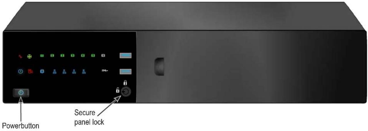
The front panel of Vess Class A Series enclosures provide access to drives carriers. Some A-Series units are shipped with secure covers to protect the drive carriers from being unintentionally removed.
For all Vess Class A Series enclosures, defective drives can be replaced without interruption of data availability to the host computer. If so configured, a hot spare drive will automatically replace a failed drive, securing the fault-tolerant integrity of the logical drive. The self-contained hardware-based RAID logical drive provides maximum performance in a compact external enclosure.
FRONT OF VESS A2600/A2600s
The Vess A2600/A2600s enclosure features handles on each side used to secure the enclosure to an equipment rack. The system power button and two USB ports are located on the left side, and most of the front LED indicators are located on the right side.
Vess A2600s/A2600 front view with secure cover

Vess A2600s/A2600 front view

FRONT PANEL LEDs
Descriptions of the LED behavior and function for Vess A-Class Series enclosures.
Vess A2600/A2600s FRONT PANEL LED
Vess A2600/A2600s Front Panel LEDs - Left side

Left side LED behavior for the Vess A2600/A2600s
| LED Description | |
| OPAS USB | Lights GREEN if an OPAS device (USB disk) is detected, RED if the OPAS operation has failed, blinks GREEN when an OPAS operation is in progress. |
| Drive Carrier LEDs (located on all drive carriers) | |
| Drive Status | Each drive carrier has two LEDs on the right side of the front, the Drive Status LED located above the Activity LED. The Drive Status LED displays GREEN when a drive is configured and working properly. When the lights are RED the HDD requires manual replacement. ORANGE indicates background RAID activity on this particular HDD, no user action is required. |
| Drive Activity | Flashes BLUE during drive activity. |
Vess A2600/A2600s Front Panel LEDs - Right side

Right side LED behavior for the Vess A2600/A2600s
| LED Description | |
| Power | Lights BLUE to indicate the system is powered on. Blinks BLUE in shutdown mode. |
| System Status | Lights GREEN when healthy, RED if there is a critical problem (LD offline, fan malfunction, voltage out of range, system temperature alert), blinks RED for HDD high temperature alert remains dark when not ready. |
| Global RAID Status | Lights GREEN when healthy or RED if any RAID volume is offline, ORANGE for critical state of any logical drive. |
| Global HDD Activity | Blinks BLUE to indicate one or more drives are being accessed, remains dark when no drives are being accessed. |
| Recording | RED indicates application running. |
| System Heartbeat | Blinks BLUE slowly at regular intervals to indicate the firmware and software are operating normally. |
FRONT OF VESS A2200/A2200s
The Vess A2200 and Vess A2200s are shipped with a lockable front secure cover to provide physical security for installed hard disks and cooling unit module. Use the tubular key shipped with the unit to lock or unlock this cover to access the six hard drive carrier trays and removable cooling unit in front.
The left panel contains the power button, various LEDs, USB ports and the tubular lock.
Vess A2200s/A2200 front view with secure cover
Vess A2200s/A2200 front view with cover removed

Vess A2200/A2200s FRONT PANEL LED
Vess A2200/2200s Left panel LED

flowchart
graph TD
    A["Power"] --> B["Power button"]
    C["System Status"] --> D["Fan Status"]
    E["Global RAID Status"] --> F["1 2 3 4 5 6"]
    G["HDd Status LEDs"] --> H["1 2 3 4 5 6"]
    I["Recording"] --> J["Power button"]
    K["HDD Activity"] --> L["Network Link/Activity"]
    M["OPAS USB"] --> N["1 2 3 4 5 6"]
Front panel LED behavior for Vess A2200/A2200s system:
| LED | Description |
| Power | Lights BLUE to indicate the system is powered on. Blinks BLUE in shutdown mode. |
| System Status | Lights GREEN when healthy, RED if there is a critical problem (LD offline, fan malfunction, voltage out of range, system temperature alert), blinks RED for HDD high temperature alert remains dark when not ready. |
| Global RAID Status | Lights GREEN when healthy or RED if any RAID volume is offline, ORANGE for critical state of any logical drive. |
| Global HDD Activity | Blinks BLUE to indicate one or more drives are being accessed, remains dark when no drives are being accessed. |
| HDD Status | One LED for each HDD carrier. Each LED lights GREEN when healthy, RED if the RAID member is offline or there is a physical disk error, ORANGE indicates the drive is rebuilding, and a dark LED indicates either no drive is installed or the drive is not configured. |
| Fan Status | Lights GREEN when healthy, RED indicates a fan in the CPU module is not operating in normal range, ORANGE indicates the CPU fan module is not present. |
| Network | One LED for each LAN port. Lights BLUE to indicate a valid link, blinks BLUE to indicate activity on the port. |
| OPAS USB | Lights GREEN if an OPAS device (USB disk) is detected, RED if the OPAS operation has failed, blinks GREEN when an OPAS log dump is in progress. |
| Recording | RED indicates application running. |
REAR PANEL HARDWARE
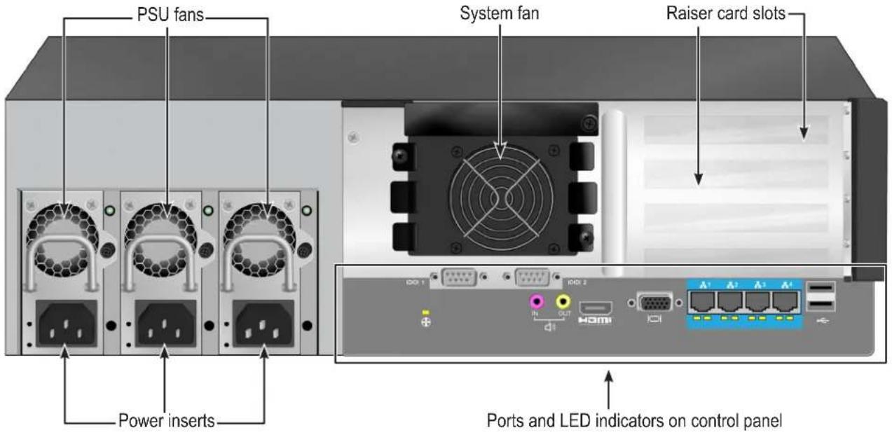
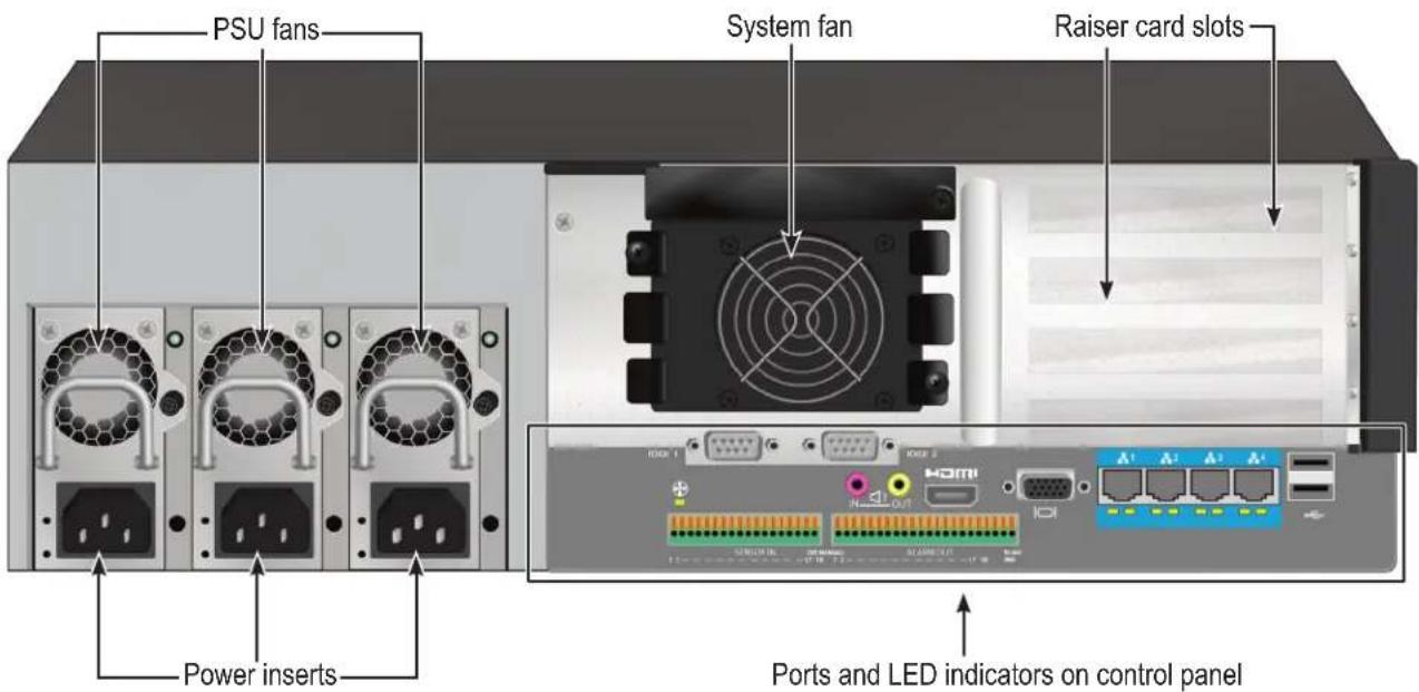
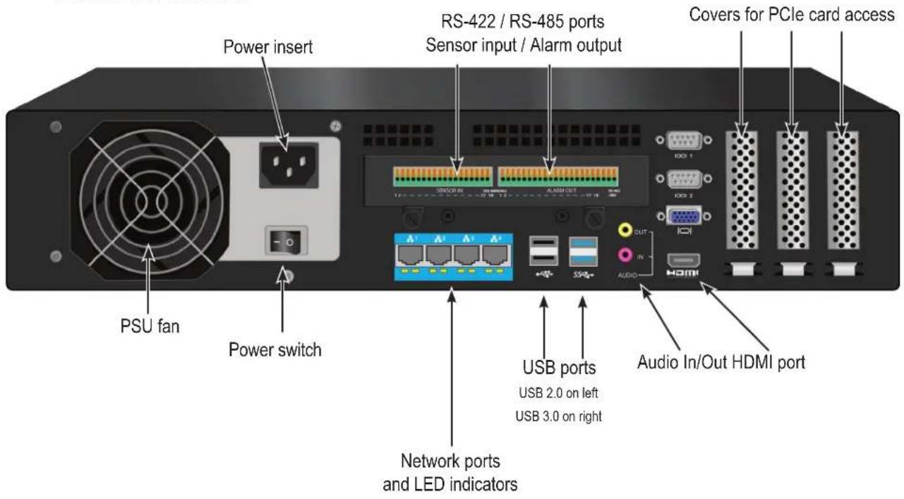
The backplane of the Vess A-Class Series enclosure provides access to the power supply (or power supplies), local management connection (via USB keyboard and VGA or HDMI monitor port), iSCSI (Ethernet) data ports, some units also provide I/O connections for audio sensor and alarm systems. The A2600/A2600s backplate includes the system fan.
Vess A2600/A2600s REAR PANEL OVERVIEW
The Vess A2600 enclosure features 3 hot-swappable power supplies (PSU) while the Vess A2600s enclosure is equipped with a single PSU that is not hot-swappable. Both enclosures are available with the alarm (RS-422) and audio (RS-485) I/O terminal block connection option. For detail on the control panel connections and LED indicators, please see the relevant sections below.

Note
The Vess A2600s featuring a single power supply will not be available for general distribution. This model will be made available by special order only.
Vess A2600s rear view

Vess A2600s with optional sensor/alarm IO ports rear view

Vess A2600 rear view
Vess A2600 with optional sensor/alarm IO ports rear view
The Vess A2600/A2600s data and management connections are located on the backplate below the cooling unit and to the right of the PSU (PSUs).
Vess A2600/A2600s backplate connections and LED indicators
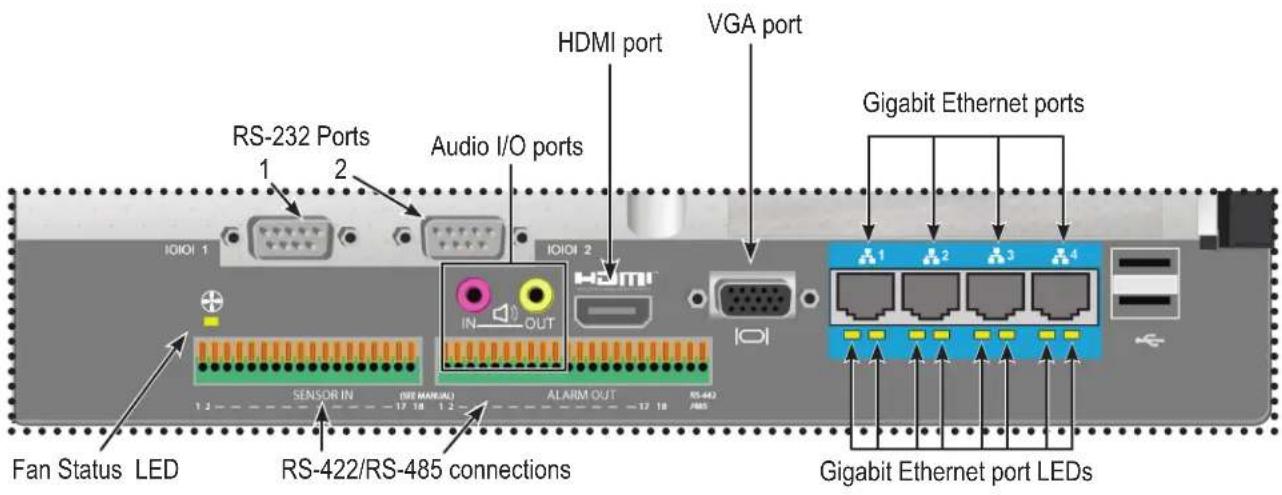
Vess A2600 BACKPLATE LED INDICATORS
The LEDs on the backplate include LEDs for System Fan and Ethernet data ports. The A2600 also has an LED on each of the hot-swappable PSUs.
| LED | Description |
| System Fan | A steady GREEN LED indicates normal fan function. A RED LED indicates fan failure, the fan must be replaced. |
| Ethernet Link/Act and Speed | The LED located below each port, on the left side, lights GREEN when connected, flashes GREEN when there is activity on the port and remains dark no connection has been established. The LED on the lower right of each port indicates connection speed, GREEN is 100 Mbps, ORANGE is 1000 Mbps. |
| PSU (Vess A2600) | The power supply LEDs on the A2600 light GREEN to indicate normal operation. A RED LED indicates a problem or unit failure. |
Vess A2600 BACKPLATE CONNECTIONS
Access to physical data and management connections are located on the backplate of the Vess A2600/A2600s including the optional I/O connections for sensor and alarm systems.
| Feature | Description |
| HDMI | Provides video out connection for HDMI enabled monitors used to view the management interface using CLI, CLU or WebPAM PROe. |
| VGA | This is also used for a video out connection for VGA monitors, it is also used to view the management interface using CLI, CLU or WebPAM PROe. |
| USB | Use to connect to a USB keyboard for managing the Vess A-Class Series, or use it to transfer data to or from a USB memory device. |
| RS-232 Port 1 | This is used for control line connection to an uninterruptible power supply (UPS). |
| RS-232 Port 2 | Use this to connect to analog cameras via the analog camera input cable.Note: This connector cannot be used at the same time as the RS-422/485 connector. |
| Audio In | Use for input from a peripheral audio device, such as a microphone. Plug-In Power microphones are supported. |
| Audio Out | Use for output (line out) peripheral audio device (speakers, for example). |
| RS-422/RS-485 | Use this to connect to analog cameras via the analog camera input cable.Note: This connector cannot be used at the same time as the RS-232 connector. |

Note
Analog camera connections are available through either the RS-232 Port 2 or the RS-422/RS-485 connections. These cannot be used simultaneously.
Vess A2200/A2200s BACKPLATE OVERVIEW
The Vess A2200 enclosure features 3 hot-swappable power supplies (PSU) while the Vess A2200s enclosure is equipped with a single PSU that is not hot-swappable. Both enclosures are available with the alarm sensor (RS-422) and audio (RS-485) I/O terminal block connection option. For detail on the control panel connections and LED indicators, please see the relevant sections below.
Vess A2200s rear view

Note
The Vess A2200s featuring a single power supply will not be available for general distribution. This model will be made available by special order only.
The Vess A2200 is identical to the Vess A2200s except that it includes an N+1 power supply arrangement.

Vess A2200 and Vess A2600 Power Supply Status LEDs

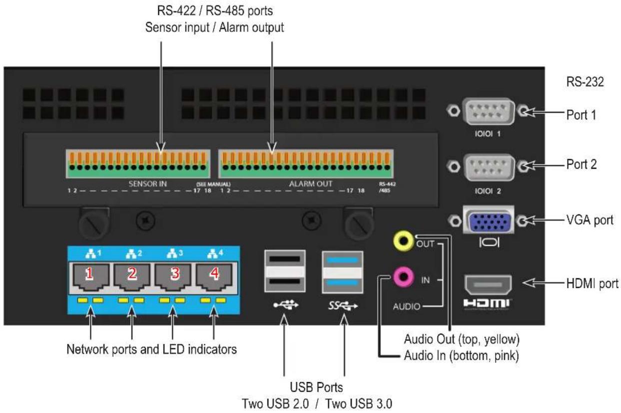
Ports and LEDs on rear panel of Vess A2200/A2200s
Vess A2200 BACKPLATE LED INDICATORS
The LEDs on the backplate include LEDs for System Fan and Ethernet data ports. The Vess A2200 also has an LED on each of the hot-swappable PSUs.
| LED | Description |
| Ethernet Link/Act and Speed | The LED located below each port, on the left side, lights GREEN when connected, flashes GREEN when there is activity on the port and remains dark no connection has been established. The LED on the lower right of each port indicates connection speed, GREEN is 100 Mbps, ORANGE is 1000 Mbps. |
| PSU (Vess A2600) | The power supply LEDs on the A2600 light GREEN to indicate normal operation. A RED LED indicates a problem or unit failure. |
Vess A2200 BACKPLATE CONNECTIONS
Access to physical data and management connections are located on the backplate of the Vess A2200/A2200s including the optional I/O connections for sensor and alarm systems.
| Feature | Description |
| HDMI | Provides video out connection for HDMI enabled monitors used to view the management interface using CLI, CLU or WebPAM PROe. |
| VGA | This is also used for a video out connection for VGA monitors, it is also used to view the management interface using CLI, CLU or WebPAM PROe. |
| USB | The backplate of the A2200/A2200s features two USB 2.0 and two USB 3.0 ports. Use to connect to a USB keyboard for managing the Vess A-Class Series, or use it to transfer data to or from a USB memory device. |
| RS-232 Port 1 | This is used for control line connection to an uninterruptible power supply (UPS). |
| RS-232 Port 2 | Use this to connect to analog cameras via the analog camera input cable.Note: This connector cannot be used at the same time as the RS-422/485 connector. |
| Audio In | Use for input from a peripheral audio device, such as a microphone. Plug-In Power microphones are supported. |
| Audio Out | Use for output (line out) peripheral audio device (speakers, for example). |
| RS-422/RS-485 | Use this to connect to analog cameras via the analog camera input cable.Note: This connector cannot be used at the same time as the RS-232 connector. |

Note
Analog camera connections are available through either the RS-232 Port 2 or the RS-422/RS-485 connections. These cannot be used simultaneously.
HARDWARE SETUP
This chapter presents the basics on unpacking, setting up hardware for the Vess A2600/A2600s and Vess A2200/2200s. Hardware installation includes installing the unit in an equipment rack, connecting the power, making network, data and management connection to the device, and installing hard drives.
The sections in Hardware Setup include the following:
- "Unpacking"
- "Mounting the Vess Class A Series in a rack"
- "Mounting a 2U enclosure in a Rack" (Vess A2200/Vess A2200s)
- "Mounting a 3U enclosure in a Rack" (Vess A2600/Vess A2600s)
- "Installing Disk Drives"
• "Number of Drives Required"
- "Remove Drive Security Cover (Vess A2200/A2200s)"
- "Drive Slot Numbering"
• "Vess A2600 drive carriers"
• "Vess A2200 drive carriers"
• "Management Path Connections"
- "Connect the Power"
- "Power On Enclosure"
• "Power On Vess A2600/A2600s"
• "Power On Vess A2200/A2200s"
- "Connect to iSCSI Storage Area Network (SAN)"
• "Install Riser Card in Vess A2600/A2600s"
• "Install PCIe cards in Vess A2200/A2200s"
UNPACKING

Note
The Vess Class A Series can accommodate SATA (3Gbps/6Gbps) hard drives.
PACKING LIST
The Vess A2600/A2600s box contains the following items:
• Vess A2600s or A2600
• Quick Start Guide printed
(Note that the Product Manual is found on the desktop after booting up and logging in)
- Screws for disk drives (70 pieces for 16-bay)
• 1.5m (4.9 ft) Power cords
(3 cords for A2600 3 PSU,
1 cord for A2600s 1 PSU )
- Sliding rail assembly for rack mounting*
- Front panel bezel cover*
The Vess A2200/A2200s box contains the following items:
• Vess A2200s or A2200
- Quick Start Guide printed (Note that the Product Manual and this Quick Start Guide, in PDF format, are found on the desktop after booting up and logging in)
- Screws for disk drives (40 pieces for 6 bays)
* These items might be an optional feature in your region. Please contact your sales representative to learn whether this is included or an option for your Vess Class A Series enclosure.
• 1.5m (4.9 ft) Power cords
(3 cords for A2200 3 PSU, 1 cord for 1 PSU A2200s)
- Sliding rail assembly for rack mounting*
MOUNTING THE VESS CLASS A SERIES IN A RACK
The instructions here apply to the Vess Class A Series. Follow the instructions according to the form factor of the Vess enclosure you are installing.
Cautions

- Do not populate any unit with hard drives until it has been securely installed in the rack.
- At least two persons are required to safely lift, place, and attach the Vess unit into a rack system.
- Do not lift or move the Vess unit by the handles, power supplies or the controller units. Hold the system itself.
- Do not install the Vess unit into a rack without rails to support the system.
- Only a qualified technician who is familiar with the installation procedure should mount and install the Vess unit.
- Mount the rails to the rack using the appropriate screws and flange nuts, fully tightened, at each end of the rail.
- Do not load the rails unless they are installed with screws as instructed.
- The rails available for the PROMISE Vess unit are designed to safely support that PROMISE Vess unit when properly installed. Additional loading on the rails is at the customer's risk.
- PROMISE Technology, Inc. cannot guarantee that the mounting rails will support your PROMISE Vess unit unless you install them as instructed.

Note
To lighten the Vess enclosure, you can remove the power supplies. Replace the power supplies after the Vess unit is mounted in your rack.

Note
Please refer to the Quick Installation Guide included with the mounting rails for more detailed rack installation instructions.
MOUNTING A 3U ENCLOSURE IN A RACK
To install the Vess into a rack with the supplied mounting rails:
- Check the fit of the mounting rails in your rack system.
-
Adjust the length of the mounting rails as needed.
-
The rear rail slides inside the front rail. The rail halves are riveted together and use no adjustment screws.
• The front-left and front-right mounting rail ends are labeled. - Be sure the front rail support is on the bottom facing inward.

- All rail ends, front and rear, attach at the outside of the rack posts.
- The guide pins at the rail ends align with the holes in the rack posts.
- Use the attaching screws and flange nuts from your rack system. Tighten the screws and nuts according to instructions for your rack system.
Rail ends attach to the outside of each post

-
Place the Vess onto the rails.
-
At least two persons are required to safely lift the system.
- Lift the Vess itself. Do not lift the system by its brackets.
Placing the Vess system onto the rack rails

-
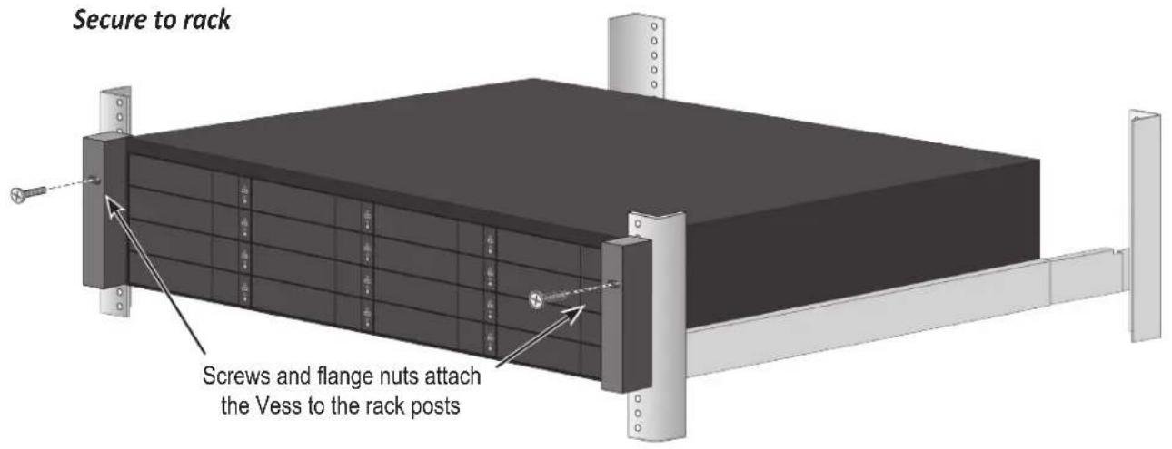
Secure the enclosure to the rack.
-
The unit attaches to the rack posts using the included screws and flange nuts. One screw each side, in the upper hole only.
- Use the attaching screws and flange nuts that came with the Vess.
System installed in rack

MOUNTING A 2U ENCLOSURE IN A RACK
The instructions here apply to the Vess A2200s and Vess A2200.
Vess A2200/A2200s with rail brackets and handles attached

natural_image
3D rendering of a black server rack with green connectors and an orange internal panel (no text or symbols visible)Follow the mounting rail instructions to attach the Rail brackets on each side of the enclosure, and the handles on the front.
To install the Vess A2200/A2200s into a rack with the supplied mounting rails:
- Check the fit of the mounting rails in your rack system.
- Adjust the length of the mounting rails as needed.
Installing the rails onto the rack

Place enclosure into the mounting rails

-
Insert the rail brackets attached to the Vess enclosure into the rails.
-
At least two persons are required to safely lift the system.
- Lift the enclosure itself. Do not lift the system by its brackets or handles.
System installed in rack viewed from rear

natural_image
Front view of a server rack unit with multiple ports and connectors, shown from top and side (no text or labels visible)-
Secure the enclosure to the rack.
-
The unit attaches to the rack posts using the included screws and flange nuts.
- Use the attaching screws and flange nuts that came with the Vess A2200/A2200s enclosure.
INSTALLING DISK DRIVES
The Vess Class A Series subsystems support:
- SATA hard disks
• 3.5-inch hard disk drives
For a list of supported physical drives, download the latest compatibility list from the PROMISE support website.
NUMBER OF DRIVES REQUIRED
The table below shows the number of drives required for each RAID level
| Level | Number of Drives | Level | Number | of Drives |
| RAID 0 1 or | more RAID 6 4 to 32 | |||
| RAID 1 2 only | RAID 10 4 or more* | |||
| RAID 1E 2 or | more RAID 30 6 or more | |||
| RAID 3 3 to | 32 RAID 50 6 or more | |||
| RAID 5 3 to | 32 |
*Must be an even number of drives.

Caution
The Vess supports disk drive hot-swapping. To avoid hand contact with an electrical hazard, do not remove more than one drive carrier a time.
REMOVE DRIVE SECURITY COVER (Vess A2200/A2200s)
To remove the security cover in front of the drive bays:
- Use the tubular key to unlock the cover. Turn counterclockwise to unlock.
- Slide the cover to the right about 4 ~mm .
- Pull the cover straight back to remove. Be careful not to drop the cover
Open security cover

Pull back cover to remove

DRIVE SLOT NUMBERING
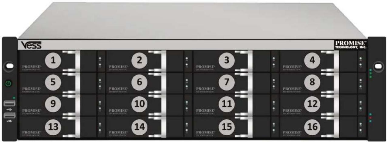
You can install any suitable disk drive into any slot in the enclosure. The diagram below shows how drive slots are numbered on both the Vess A2200s and Vess A2200.
Slot numbering is reflected in the web manager GUI and CLI/CLU user interfaces.
Drive slot numbering for Vess A2200s/A2200

Drive numbers (odd) Drive numbers (even)
Install all of the drive carriers into the enclosure to ensure proper airflow, even if you do not populate all the carriers with disk drives.
Drive slot numbering for Vess A2600s/A2600
Vess A2600/A2600s drive carrier (empty)

Vess A2600 DRIVE CARRIERS
The instructions below apply to drive carriers used with the Vess A2600 or Vess A2600s.
- Grasp the handle and slide the latch to the left as far as it goes.
- Press the square button to the right of the latch to release it. The latch with pop out.
- Pull the latch out to open the door and lever the tray part of the way out. Then pull the latch straight back about 2 centimeters to expose the front portion of the tray assembly. Grasp the corners of the front assembly with the thumb and forefinger of each hand and pull the tray completely out of the enclosure, sliding it straight out. The tray is now ready to receive a new hard disk.

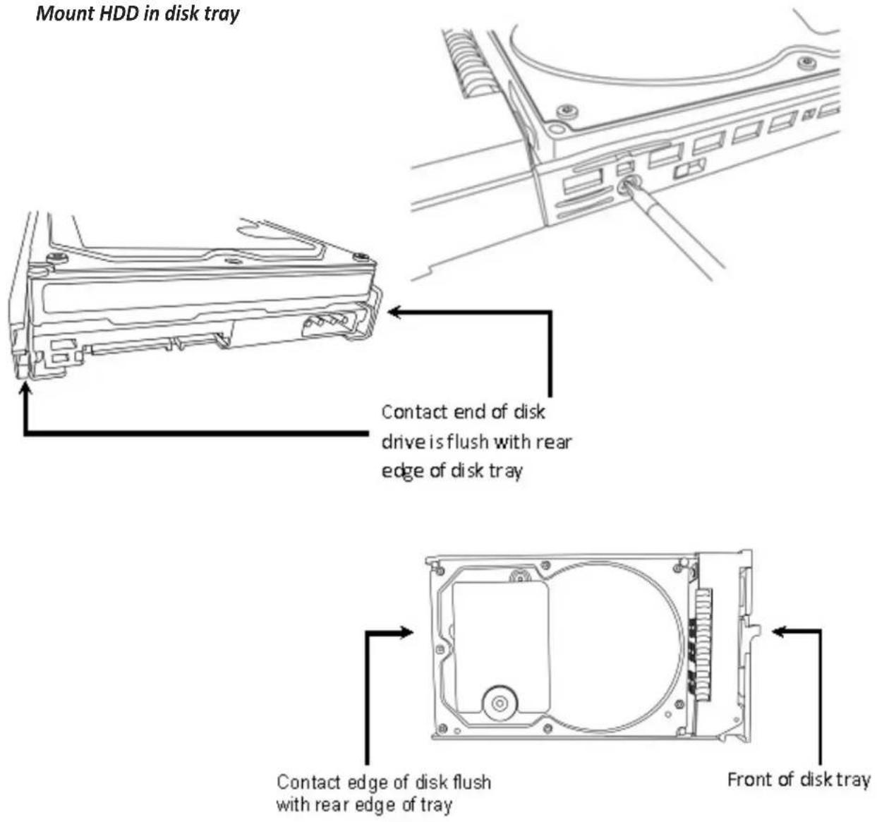
- Carefully lay the disk drive into the drive carrier at the front, so that the screw holes on the sides line up.
- Insert the screws through the holes in the drive carrier and into the sides of the disk drive.
Install only the counter-sink screws supplied with the drive.
• Install four screws per drive.
- Snug each screw. Be careful not to over-tighten.
3. Reinstall the drive carrier into the enclosure.
Repeat steps 1 through 3 until all of your disk drives are installed.
Mount HDD in disk tray
Vess A2200 DRIVE CARRIERS
The instructions below apply to all types of drive carriers intended for use with the Vess A2200 or Vess A2200s.
- Remove a disk drive carrier.
- Carefully lay the disk drive into the drive carrier at the front, so that the screw holes on the sides line up.
- Insert the screws through the holes in the drive carrier and into the sides of the disk drive.
Install only the counter-sink screws supplied with the drive.
• Install four screws per drive.
- Snug each screw. Be careful not to over-tighten.
4. Reinstall the drive carrier into the enclosure.
Repeat steps 1 through 3 until all of your disk drives are installed.
SATA disk drive mounted in a Vess A2200/A2200s drive carrier

Vess A2200/A2200s Disk carrier with HDD installed - front view

Tabs for locking mechanism insert. This piece must be removed to unlatch the carrier. To remove, squeeze the tabs together and pull out. To reinsert, squeeze the tabs together and replace in position. Do not discard the locking mechanisms.

Caution
The Vess Class A Series supports disk drive hot-swapping. To avoid hand contact with an electrical hazard, do not remove more than one drive carrier a time.
MANAGEMENT PATH CONNECTIONS
This section describes how to establish a management connection the Vess A2600/A2600s and Vess A2200/A2200s subsystems. There are two methods to establish the physical connection used for management of the device. Management through the Gigabit network connection is done using WebPAM PROe, a web browser based GUI. Alternatively you can use an out-of-band connection using a VGA or HDMI monitor and USB keyboard to access the embedded text-based CLI/CLU interface.
MANAGEMENT PATH - NETWORK CONNECTION
Vess A2600/A2600s and Vess A2200/A2200s have four Gigabit Ethernet RJ-45 ports on the rear panel for connection to an Ethernet network. Use this connection with WebPAM PROe to login as the device administrator.
To establish the management path:
-
Attach one end of an Ethernet cable to the network connector or standard NIC in the Host PC. Attach the other end of the Ethernet cable to one of the ports on the standard network switch.
-
Attach one end of an Ethernet cable to one of the ports on the standard network switch. Attach the other end of the Ethernet cable to the Management Port on the Vess system.
If you have multiple Vess systems, Host PCs or Servers, repeat steps 1 and 2 as required.
- Follow the instructions for managing the basic settings of the Vess.
MANAGEMENT PATH - ON SITE KEYBOARD AND MONITOR
Use a USB keyboard and a VGA or HDMI monitor to establish a local out-of-band connection to the Linux-based or Windows 7 operating system. The VGA port, HDMI and USB ports are also located on the rear panel of the Vess, these are enabled by default upon booting up the system. Connect a VGA or HDMI monitor to the appropriate port on the Vess, and connect a USB keyboard to either USB port on the rear panel.
Vess A2200/A2200s Ethernet, video monitor connections and USB ports
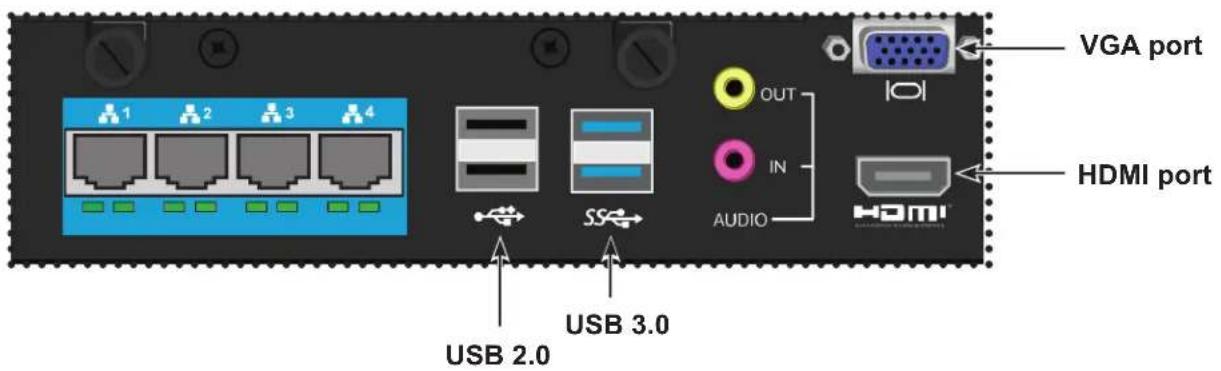
Vess A2600/A2600s Ethernet, video monitor connections and USB ports


Important
Be sure to place the monitor and keyboard on a stable and secure surface before connecting them.
CONNECT THE POWER
Insert one power cable into the power receptacle for each power supply and connect the each PSU to a suitable power source. The Vess A2600s and Vess A2200s are equipped with a single power supply (see below). The Vess A2600 and Vess A2200 are equipped with three power supplies in an N+1 arrangement.
Vess Class A Series single PSU power connection

The Vess A2600 and Vess A2200 feature three N+1 power supplies. In this arrangement, one PSU is redundant, so a minimum of two PSUs are needed to power up the enclosure.
Vess A-2600 N+1 power connections

Vess A2200 N+1 PSUs
Each PSU has a Status LED. After boot up, check the LEDs on each power supply on the back of the device. These LEDs will light green to indicate normal operation. A red LED indicates a problem or unit failure.

Important
There are three LED indicators on the N+1 power supplies. Check these after powering the devices on to make sure the cooling and power status for the power module is normal.
POWER ON ENCLOSURE
With the power supplies connected, the system can now be powered on.
POWER ON VESS A2600/A2600s
To power on the Vess A2600/A2600s, press the Power button on the front left bracket facing (see figure below). Observe the LEDs on the front panel to make certain the boot up proceeds smoothly.
Vess A2600/A2600s front left side

Vess A2600/A2600s front right side
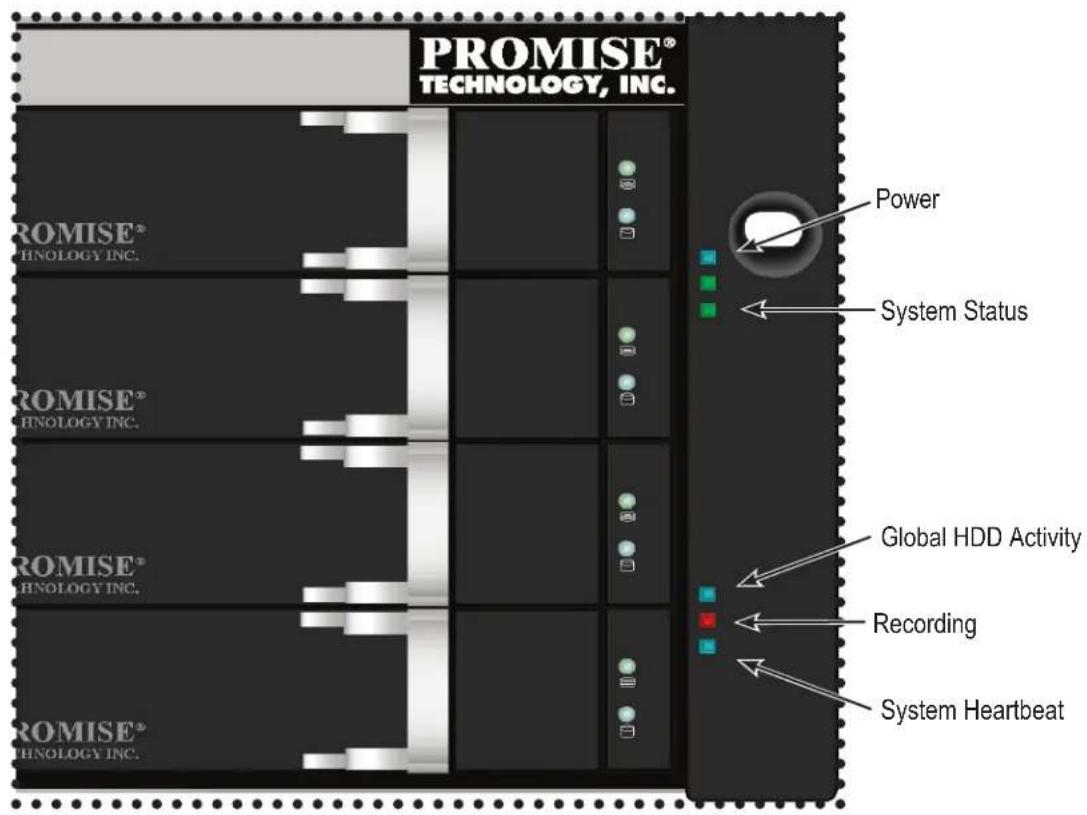
FRONT PANEL LEDs AFTER POWER ON - VESS A2600/A2600s
When the boot-up is finished and the Vess A2600/A2600s system is functioning normally:
| LEDDescription | |
| Power | Lights BLUE to indicate the system is powered on. Blinks BLUE in shutdown mode. |
| System Status | Lights GREEN when healthy, RED if there is a critical problem (LD offline, fan malfunction, voltage out of range, system temperature alert), blinks RED for HDD high temperature alert remains dark when not ready. |
| System Heartbeat | Blinks BLUE slowly at regular intervals to indicate the firmware and software are operating nor-mally. |
REAR PANEL LEDs AFTER POWER ON - VESS A2600/A2600s
When system boot-up is finished, use the LEDs on the controller on the rear of the device to monitor various functions (described below).
| LED Description (refer to product manual for more details) | |
| System Fan | A steady GREEN LED indicates normal fan function. A RED LED indicates fan failure, the fan must be replaced. |
| Ethernet Link/Act and Speed | The LED located on below each port, on the left side, lights green when connected, flashes green when there is activity on the port and remains dark no connection has been established. The LED on the lower right of each port indicates connection speed, green is 100 Mbps, ORANGE is 1000 Mbps. |
Vess A2600/A2600s rear panel LEDs

POWER ON VESS A2200/A2200s
With the power supplies connected, the system can now be powered on.
To power on the Vess A2200 or Vess A2200s, press the Power button in the lower left corner of the front panel (see figure below). Observe the LEDs on the front panel to make certain the boot up proceeds smoothly.
Vess A2200/A2200s front left side

When the boot-up is finished and the Vess A2200/A2200s system is functioning normally:
| LEDDescription | |
| Power | Lights BLUE to indicate the system is powered on. Blinks BLUE in shutdown mode. |
| System Status | Lights GREEN when healthy, RED if there is a critical problem (LD offline, fan malfunction, voltage out of range, system temperature alert), blinks RED for HDD high temperature alert remains dark when not ready. |
| HDD Status | One LED for each HDD carrier. Each LED lights GREEN when healthy, RED if the RAID member is offline or there is a physical disk error, ORANGE indicates the drive is rebuilding, and a dark LED indicates either no drive is installed or the drive is not configured. |
| Fan Status | Lights GREEN when healthy, RED indicates a fan in the CPU module is not operating in normal range, ORANGE indicates the CPU fan module is not present. |
| Network | One LED for each LAN port. Lights GREEN to indicate a valid link, blinks GREEN to indicate activity on the port. |
CONNECT TO ISCSI STORAGE AREA NETWORK (SAN)

Important
For a list of supported HBA NICs and switches, download the latest compatibility list from PROMISE support: http://www.promise.com/support/.
This arrangement requires:
• An iSCSI HBA network interface card (NIC) in the host PC or server
• A GbE network switch
• A standard network switch

Note
Only one iSCSI data cable is required between each Vess enclosure and the GbE network switch. However, you can attach multiple cables to create redundant data paths or trunking.
Vess A2600/A2600s Gigabit ports for iSCSI SAN

1Gb/s Data Ports
Vess A2200/A2200s Gigabit ports for iSCSI SAN

1Gb/s Data Ports
INSTALL RISER CARD IN VESS A2600/A2600s
The controller module can accommodate an optional riser card. There are two riser cards available. One is used for installation of up to four PCIe cards, another is used for a single graphics card. The installation procedure for is the same for both form factors. Follow the instructions in this section to complete the hardware installation of the riser card and PCIe cards. Contact your sales representative for information about the available form factors for installing a riser card. A list of approved graphics cards for use with the graphics card riser is available at promise.com.
For PCIe card or graphics card driver installation, follow the instructions of the manufacturer of the card.
The hardware installation steps can be summarized as follows:
- Shut down the system and power off the enclosure. To shutdown the system, perform the normal shutdown procedure according to the operating system being used. When the system is shut down, remove the power cords from the power cord inserts on the power supplies.
- Remove the controller module and place it on a desktop or suitable work area.
- Remove the fan module and a punch-out cover for the slot where the PCIe card can be accessed from the backplate of the Vess controller.
- Attach the mounting bracket included with the riser card shipment.
- Insert the riser card and secure it to the mounting bracket.
- Loosen and open the PCIe bracket guard
- Insert a PCIe card and secure it to the controller housing.
- Close and tighten the PCIe bracket guard, replace the fan module and replace the controller module in the Vess system chassis.

Warning
Turn off the power and disconnect all power cord before servicing the Vess A2600 or Vess A2600s.
STEP 1: REMOVE CONTROLLER MODULE
To remove the controller module of the Vess A2600 or Vess A2600s:
- Power off the Vess system and wait until it is completely shut down.
- Use a Phillips head screwdriver or your fingers to loosen the screw that secures the lever used to remove and insert the controller, then pull the lever out so that the controller is unseated from the Vess chassis.
- Pull the controller module straight back and out of the Vess chassis.
STEP 2: REMOVE FAN MODULE
To remove the fan module from the controller:
- Use a Phillips head screwdriver to remove the two screw that secure the fan, one screw is in the upper left corner, the other in the lower right corner of the module.
- Pull the fan module out of the controller.
See illustration on next page.
Vess A2600 controller module - remove fan

STEP 3: ATTACH MOUNTING BRACKET
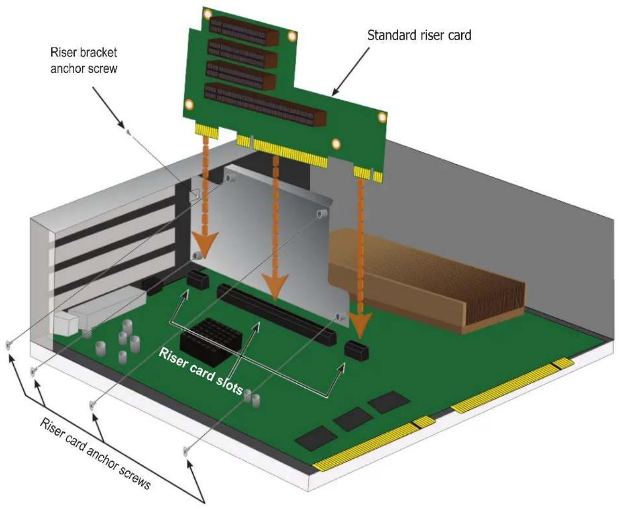
The riser card includes a mounting bracket used to anchor the card in position. The bracket is secured to the controller module housing with a screw on the backplate of the controller, the screw hole is revealed when the fan module is removed. Position the bracket so that the anchor posts used to mount the riser card in position are facing the open side of the controller housing. Then secure the bracket to the backplate of the module with the screw included with the mounting bracket.
STEP 4: INSERT RISER CARD
When the mounting bracket is properly positioned and secured, the riser card will be able to align to the insertion into the riser card slots on the controller PCB. Insert the card into the slots so that the card is firmly seated in place. Then anchor the riser card with the four anchor screws included with the shipment.
See illustration on next page.
Attach bracket and insert riser card

Note
The riser card used for installation of a graphics card has a single 16-lane PCI slot located near the top edge of the riser card. Talk to a sales representative if you intend to install a graphics card in the Vess A2600.
Do not use the standard riser card for installing a graphics cards.
STEP 5: INSERT PCIe CARD
The riser card is now ready to receive a PCIe card. See illustration on next page.
Note that the standard riser card can accommodate the following form factors:
• One 16-lane Generation 2.0 PCI Express slot
• Three 8-lane Generation 2.0 PCI Express slots
The special graphics riser card has one 16-lane Generation 2.0 PCI Express slot. The procedure for installing the hardware is the same. Contact your sales representative to order the graphics riser card. A list of approved graphics cards is posted online at promise.com.
To insert a PCIe card, follow these steps:
- Use a Phillips head screwdriver or your fingers to loosen the PCIe bracket guard screw and swing the guard open to access the PCIe card anchor screw holes.
- Insert the PCIe card so that it is firmly seated in an available slot on the riser card.
- Secure the PCIe bracket to the module housing. When properly positioned the port(s) on the PCIe card will be accessible from the backplate and the PCIe bracket will be flush with the backplate.
- Swing the bracket guard closed and secure it with the attached screw.
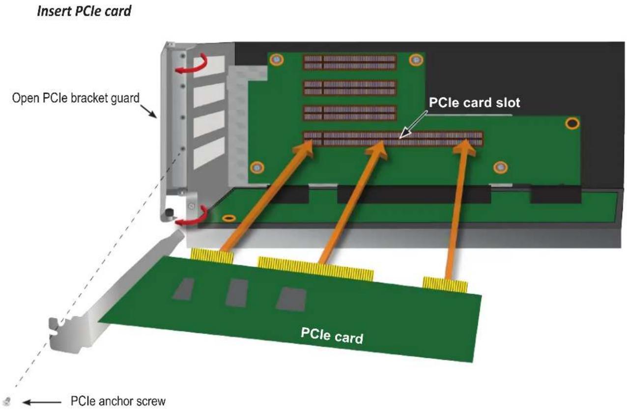
STEP 6: REASSEMBLE
With the riser card and PCIe cards in place, return the fan module into position and secure it with the fan module screws.
The controller module can now be returned to the Vess chassis. Insert the module into the chassis and push it into position, then use the lever to complete the insertion so that the module is firmly seated in the Vess chassis. Tighten the lever screw.
INSTALL PCIe CARDS IN VESS A2200/A2200s
Up to three PCIe cards can be installed in the Vess A2200/A2200s. The PCIe slots can accommodate the following form factors:
• One 16-lane Generation 2.0 PCI Express slot*
- Two 8-lane Generation 2.0 PCI Express slots*
The hardware installation is similar to installing a PCIe card on a desktop PC. The procedure is summarized as follows:
- Shut down the device and disconnect the power cord or cords.
- Remove the housing cover, i.e. the top of the device housing.
- Remove the reusable cover for the PCIe opening to be used on the backplate and insert the PCIe card.
- Replace the housing cover.

Warning
Turn off the power and disconnect all power cord before servicing the Vess A2200 or Vess A2200s.
STEP 1: SHUT DOWN SYSTEM, DISCONNECT POWER
Before opening the system housing, shut down the device and disconnect any power cords.
STEP 2: REMOVE HOUSING COVER
Remove housing cover

natural_image
Back view of a server rack unit with ventilation fan, ports, and connectors (no visible text or labels)-
Use a small Phillips head screwdriver to remove all five screws that secure the cover to the rest of the device housing. There are two small flat head machine screws, one on each side, and three dome head machine screws that secure the cover to the backplate.
-
Slide the cover toward the rear of the device until it can be lifted off.
STEP 3: INSERT PCIe CARD
Removal of the cover exposes the PCIe slots located in the rear left corner.
-
Pull out the protective cover for the PCIe opening for the slot that will be used. Save this protective cover for future use.
-
Insert the PCIe card so that it is firmly seated in the PCIe slot. When properly seated, the bracket will flush with the backplate of the device allowing access to the PCIe functional connection. It is not necessary to anchor the bracket with a screw since the housing cover will hold the card securely in place when the device is completely reassembled.
Remove PCIe cover and insert card

natural_image
3D diagram of a computer motherboard with a green circuit board, RAM slots, and a red dashed arrow indicating motion (no text or symbols)STEP 4: REPLACE HOUSING COVER
Now simply replace the hosing cover on the device. Place the cover into the accommodating guides on each side of the housing and push the cover back into place. Secure the cover with the five screws (one flat head screw on each side, the three remaining on the back), do not over tighten the screws.
MANAGING WITH WEBPAM PROE
This chapter describes using WebPAM PROe to monitor and manage your RAID system.
LOGGING INTO WEBPAM PROE
You can log into WebPAM PROe in either of two ways:
- "Logging in at the Enclosure" on page 58
• "Logging in over the Network" on page 59
LOGGING IN AT THE ENCLOSURE
At the Vess enclosure to log into WebPAM PROe, do one of the following actions:
- Double-click the WebPAM PROe desktop icon.
- Choose WebPAM PROe in the Windows Programs menu or the Linux Applications menu.
- Follow the steps under "Logging in over the Network" on page 59.

Note
The default IP settings for the four Gigabit Ethernet ports are:
Port 1 = 192.168.0.1
Port 2 = 192.168.1.1
Port 3 = 192.168.2.1
Port 4 = 192.168.3.1
IP settings for the ports are controlled by the OS. Use the normal IP settings configuration procedure for the OS you are using if you want to change the default settings.
LOGGING IN OVER THE NETWORK

Important
For Vess A-Class Series running Windows OS, it is necessary to disable the Windows Firewall in order to allow access to WebPAM PROe through the network interface. If the Firewall is running, no management access is permitted from the network.
You can log into WebPAM PROe from any PC with a network connection to the Vess A Class Series enclosure.
- Launch your Browser.
- In the Browser address field, type the information provided below. Then press Enter. Note that this example uses the default IP address for Port 1
If you chose External SSL Security during installation, use the Secure Connection. Otherwise, use the Regular Connection.
Regular Connection
- WebPAM PROe uses an HTTP connection....http://
- Enter the Subsystem IP address ..... 192.168.0.1
- Enter the Port number .....:8090
Together, your entry looks like this:
http://192.168.0.1:8090
Secure Connection
- WebPAM PROe uses a secure HTTP connection . . . . . . . . . . . . . . . . . . . . . . . . . . . . . . . . . . . . . . . . . . . . . . . . . . . . . . . . . . . . . . . . . . . . . . .
- Enter the Subsystem IP address ..... 192.168.0.1
- Enter the Port number .....:443
Together, your entry looks like this:
https://192.168.0.1:443/

natural_image
Simple icon of a yellow pencil inside a square frame (no text or symbols)Note
- You can enter the Host PC's network name in place of the IP address.
- If you are logging in at the Host PC, you can enter local Host in place of the IP address.
- Whether you select a regular or a secure connection, your login to WebPAM PROe and your user password are always secure.
LOGIN SCREEN
When the opening screen appears:
- Type administrator in the User Name field.
- Type password in the Password field.
- Click the Login button.
The User Name and Password are case sensitive. See Figure 1.

After logging in, the Quick Links menu appears.
Quick Links MENU
The Quick Links menu is the administrator's Home page for WebPAM PROe. Here you will find links to menus to view setting and manage logical drives, physical drives, and disk arrays. Also links to view network settings and event logs, as well as the background activities management menu.

USING THE WEBPAM PROE INTERFACE
WebPAM PROe is browser-based RAID management software with a graphic user interface. Basic user interface components and functions include:
WebPAM PROe interface - Subsystem home page

There are four major parts to the WebPAM PROe interface:
- Header
- Tree View
- Event Frame
USING THE HEADER
The Header contains the following items:
Language – Choose a display language
View – To view the Event Frame,
Logout – To logout
USING TREE VIEW
Tree View enables you to navigate around all components of the Vess enclosure, software management, RAID controller, enclosure, physical drives, disk arrays, logical drives, and spare drives. The figure below shows the components of Tree View.
WebPAM PROe Tree View

The Administrative Tools section is different for the Administrator and Super Users than for other users. The remainder of the Tree is the same for all users.
USING MANAGEMENT VIEW
Management View displays information and settings menus according to the item you choose in Tree View. It presents the user interface for the Vess enclosure, including creation, maintenance, deletion, and monitoring of disk arrays and logical drives. Function tabs access menus to control specific actions and processes.
Click the Help link to the right of the tabs in Management View to access online help for the function currently displayed.
CHOOSING A DISPLAY LANGUAGE
WebPAM PROe displays in the following languages:
- English
- Simplified Chinese
- Traditional Chinese
- French
-
German
-
Italian
- Japanese
- Korean
- Spanish
- Russian
To change the display language:
- Click the Language drop-down menu in the Header.
- Highlight the language you prefer.
WebPAM PROe displays in the chosen language.
VIEWING THE EVENT FRAME
To view the Event Frame, click Show Event Frame in the Header. To hide the Event Frame, click Hide Event Frame in the Header.
In the event frame, events are listed and sorted by:
• Device – Disk array, logical drive, physical drive, controller, etc.
- Event ID – The hexadecimal number that identifies the specific type of event
- Severity – See below:
• Information – Information only, no action is required
- Warning – User can decide whether or not action is required
- Minor – Action is needed but the condition is not serious at this time
• Major – Action is needed now
- Critical – Action is needed now and the implications of the condition are serious
- Fatal – Non-Recoverable error or failure has occurred
• Time – Time and date of the occurrence
• Description – A brief description of the event
You can also view events by clicking the Subsystems icon in Tree View, then clicking the Event tab in Management View.
LOGGING OUT OF WEBPAM PROE
There are two ways to log out of WebPAM PROe:
- Close your browser window
- Click Logout in the WebPAM PROe Header
Clicking Logout brings you back to the Login Screen. After logging out, you must enter your user name and password in order to log in again.
SUBSYSTEM MANAGEMENT
The menus listed under Subsystems are all the menus used for device management. Click on the Subsystems icon to view read-only information for the Vess including the management IP address, Alias, Model and WWN.
To view the menus used for system management, click the + symbol of the Subsystems icon to reveal the child menu icons for the following:
- Administrative Tools (includes links for User Management, View Network Settings, Performance Monitoring and Software Management)
- Controllers (view controller information and manage settings)
- Enclosures (view device information and virtual enclosure, set temperature thresholds for warnings and enable/disable warning buzzer)
• Disk Arrays (manage disk arrays) - Spare Drives (manage spare drives)
• Logical Drives Summary (read-only logical drive information display)
Click on the subsystem IP address and model name listed under the Subsystems top-level menu icon in Tree View. In the Information tab, the following information for the subsystem appears:
- Alias
- Vendor
- Model
- Serial Number
• World Wide Number - Part Number
- Revision Number
• System Date & Time
Here you can also save a System Service Report (useful for troubleshooting) in the form of an HTML file to the computer you are using by clicking on the Save button. See "Saving a Service Report".
The Subsystem home menu includes the following function tabs:
• Information (described above) • Settings (assign an Alias)
• Background Activities
• Scheduler (schedule background activities)
• Event (list runtime and NVRAM events)
- Lock (lock/unlock subsystem)
BACKGROUND ACTIVITIES
Background activities perform a variety of preventive and remedial functions on your physical drives, disk arrays, logical drives, and other components.
You can run a background activity immediately or schedule it to run at a later time.
Setting options for each activity are listed after the scheduling options. These settings determine how the background activity affects I/O performance.
VIEW CURRENT BACKGROUND ACTIVITIES
To view current background activities:
- Click the Subsystem icon of the subsystem on which you want to view Background Activities.
- In the Subsystem menu, click the Background Activities tab. Background Activities currently running are displayed in the top portion of the menu. You can also view the current Background Activities parameter settings in the lower part of the menu. Click the Background Activity Parameters menu expander to view the current parameter settings.
VIEW BACKGROUND ACTIVITIES PARAMETERS SETTINGS
To view current background parameter settings:
- Click the Subsystem icon of the subsystem on which you want to view Background Activities.
-
Click the Background Activity Parameters menu expander to view the current parameter settings. The parameters listed are as follows:
-
Rebuild Rate
• Background Synchronization Rate
• Logical Drive Initialization Rate
• Redundancy Check Rate - Migration Rate
-
PDM Rate
-
Transition Rate
- Reassigned Block Threshold
- Error Block Threshold
- Enable Media Patrol
- Enable Auto Rebuild
MANAGE BACKGROUND ACTIVITIES SETTINGS
The parameters listed in the Background Activities menu are configured in the Background Activities Settings menu. To change Background Activities settings
- Click the Subsystem icon of the subsystem on which you want to view Background Activities.
- Click the menu expander between the Background Activities tab and the Scheduler tab and select the
Settings option. The following settings can be configured:
• Rebuild Rate High, Medium, Low
• Background Synchronization Rate High, Medium, Low
• Logical Drive Initialization Rate High, Medium, Low
• Redundancy Check Rate High, Medium, Low
- Migration Rate High, Medium, Low
• PDM Rate High, Medium, Low
• Transition Rate High, Medium, Low
• Reassigned Block Threshold
- Error Block Threshold
- Enable Media Patrol
- Enable Auto Rebuild
These settings can be also scheduled using the Scheduler. See the instructions for using schedules following the parameters descriptions below.
REBUILD SETTINGS
To change Rebuild setting the in Background Activities Settings menu:
-
Use the Rebuild Rate drop-down menu to choose a rate:
-
Low – Fewer system resources to the Rebuild, more to data read/write operations.
- Medium – Balances system resources between the Rebuild and data read/write operations.
-
High – More system resources to the Rebuild, fewer to data read/write operations.
-
To enable Auto Rebuild (rebuilds when you swap out the failed drive with a new one) Check the Enable
Auto Rebuild box.
- Click the Submit button.
Rebuild Rate
When you rebuild a disk array, you are actually rebuilding the data on one physical drive.
- When a physical drive in a disk array fails and a spare drive of adequate capacity is available, the disk array begins to rebuild automatically using the spare drive.
- If there is no spare drive of adequate capacity, but the Auto Rebuild function is ENABLED, the disk array begins to rebuild automatically as soon as you remove the failed physical drive and install an unconfigured physical drive in the same slot.
- If there is no spare drive of adequate capacity and the Auto Rebuild function is DISABLED, you must replace the failed drive with an unconfigured physical drive, then perform a Manual Rebuild.
Synchronization is automatically applied to redundant logical drives when they are created. Synchronization recalculates the redundancy data to ensure that the working data on the physical drives is properly in sync.
Background Synchronization Rate
- To change Background Synchronization Rate setting the in Background Activities Settings menu: Click the
Synchronization Rate drop-down menu and choose a rate:
- Low – Fewer system resources to Synchronization, more to data read/write operations.
- Medium – Balances system resources between Synchronization and data read/write operations.
-
High – More system resources to Synchronization, fewer to data read/write operations.
-
Click the Submit button.
LOGICAL DRIVE INITIALIZATION
Technically speaking, Initialization is a foreground activity, as you cannot access a logical drive while it is initiating.
Initialization is normally done to logical drives after they are created from a disk array. Initialization sets all data bits in the logical drive to zero. The action is useful because there may be residual data on the logical drives left behind from earlier configurations. For this reason, Initialization is recommended whenever you create a logical drive.
Logical Drive Initialization Rate
To change Logical Drive Initialization Rate setting the in Background Activities Settings menu:
-
Click the Logical Drive Initialization Rate drop-down menu and choose a rate:
-
Low – Fewer system resources to Initialization, more to data read/write operations.
- Medium – Balances system resources between Initialization and data read/write operations.
-
High – More system resources to Initialization, fewer to data read/write operations.
-
Click the Submit button.
REDUNDANCY CHECK
Redundancy Check is a routine maintenance procedure for fault-tolerant disk arrays (those with redundancy) that ensures all the data matches exactly. Redundancy Check can also correct inconsistencies.

natural_image
Simple icon of a yellow pencil inside a square frame (no text or symbols)Note
You can use the scheduler to set up a Redundancy Check Schedule.
To set up a schedule, click the menu expander to the right of the Scheduler tab and select Redundancy Check Schedule.
Redundancy Check Rate
To change Redundancy Check Rate setting the in Background Activities Settings menu:
-
Click the Redundancy Check Rate drop-down menu and choose a rate:
-
Low – Fewer system resources to Redundancy Check, more to data read/write operations.
- Medium – Balances system resources between Redundancy Check and data read/write operations.
-
High – More system resources to Redundancy Check, fewer to data read/write operations.
-
Click the Submit button.
PDM
Predictive Data Migration (PDM) is the migration of data from the suspect physical drive to a spare drive, similar to rebuilding a logical drive. But unlike Rebuilding, PDM constantly monitors your physical drives and automatically copies your data to a spare drive before the physical drive fails and your logical drive goes Critical.
PDM Settings
To change PDM setting the in Background Activities Settings menu:
-
Click the PDM Rate drop-down menu and choose a rate:
-
Low – Fewer system resources to PDM, more to data read/write operations.
- Medium – Balances system resources between PDM and data read/write operations.
-
High – More system resources to PDM, fewer to data read/write operations.
-
Highlight the current values in the block threshold fields and input new values.
Reassigned Block Threshold range is 1 to 512 blocks.
Error Block Threshold range is 1 to 2048 blocks.
- Click the Submit button.
TRANSITION
Transition is the process of replacing a revertible spare drive that is currently part of a disk array with an unconfigured physical drive or a non-revertible spare drive.
Transition Rate
To change Transition Rate setting the in Background Activities Settings menu:
-
Click the Transition Rate drop-down menu and choose a rate:
-
Low – Fewer system resources to Transition, more to data read/write operations.
- Medium – Balances system resources between Transition and data read/write operations.
-
High – More system resources to Transition, fewer to data read/write operations.
-
Click the Confirm button.
MEDIA PATROL
Media Patrol is a routine maintenance procedure that checks the magnetic media on each disk drive. Media Patrol checks are enabled by default on all disk arrays and spare drives. Media Patrol is concerned with the media itself, not the data recorded on the media. If Media Patrol encounters a critical error, it triggers PDM if PDM is enabled on the disk array.
Media Patrol Settings
Media Patrol is enabled or disabled using the Background Activities menu or you can create a schedule to run Media Patrol.
- To enable Media Patrol, click on the Subsystem in Tree View then click on the Background Activities menu tab. Click to check the Enable Media Patrol option. Notice also that the Auto Rebuild option is here as well. If you want to automatically begin rebuilding a logical drive as soon as a faulty drive is replaced, make sure this option is enabled.
- To begin Media Patrol manually, click on the menu expander to the right of the Background Activities tab and scroll down and select Start Media Patrol to see the Start Media Patrol menu. Then click on the Start button.
- To schedule Media Patrol, click on the menu expander to the right of the Scheduler tab and scroll down and select Add Media Patrol Schedule to open the schedule menu. Use this menu to add a Media Patrol schedule.
MANAGING ACTIVITY SCHEDULES
Schedules for Media Patrol, Redundancy Check and Spare Drive Check can be created to run during off peak times.
Add or Delete an activity schedule
To add, enable or delete an activity schedule, click on the Subsystem in Tree View, then click on the Scheduler menu expander to the right of the Scheduler tab. Scroll down to the schedule option you want to view that menu. Schedule options are Add Media Patrol Schedule, Add Redundancy Check Schedule, Add Spare Check Schedule and Delete Schedule.
VIEW OR MODIFY AN EXISTING ACTIVITY SCHEDULE
To view existing schedules including the recurrence, start time and status of existing schedules, click on the Scheduler tab. Here you can then modify any listed schedule by clicking on the name of the schedule in the list.
EVENT LOGS
Event logs are useful for troubleshooting, tracking functions and monitoring subsystems. To view, save or clear subsystem event logs, click on the subsystem in Tree View, then click on the Event menu expander. Choose to display Runtime Events or NVRAM Events. Event logs can be saved as a simple text file by clicking the Save button in either menu. To clear the log and start fresh, click the Clear Event Log button.
ADMINISTRATIVE TOOLS
Click the + symbol of the Administrative Tools icon reveal subsystem administrative tools menu links for User Management, View Network Settings, Performance Monitoring and Software Management. The Administrative Tools menu lists text hyperlinks to these same menus, plus links to menus to Restore Factory Default settings, Clear Statistics and Save System Service Report.
RESTORE FACTORY DEFAULT SETTINGS
To restore any firmware or software settings to the default values:
- Click on the Administrative Tools icon.
-
Click on the Restore Factory Defaults link to reveal a new menu.
-
Check mark the option boxes for the settings you want to return to the factory default values. Default Settings options include:
Firmware Default Settings
• Background Activities
- Controller Settings
- Enclosure Settings
• Physical Drive Settings
- Subsystem Settings
Software Default Settings
- Service Settings
- Web Server Settings
-
Email Settings
-
Click the Submit button to return the selected settings to default values. To deselect all options and start over, click the Reset button.
CLEAR STATISTICS
To clear all subsystem statistics for controllers, ports physical drives and logical drives:
- Click on the Administrative Tools icon.
- Click on the Clear Statistics link to reveal a new menu.
- Click on the Submit button to clear all device statistics.
USER MANAGEMENT
User Management deals with user accounts.
VIEWING USER INFORMATION
The view a list of users, their status, access privileges, display name, and email address:
- Click the Administrative Tools icon.
- Click the User Management icon.
The Information tab appears in Management View.
MAKING USER SETTINGS
To change settings of other users:
- Log into WebPAM PROe as the Administrator or a Super User.
- Click the Administrative Tools icon.
- Click the User Management icon.
- Click the Information tab.
- In the list of users, click the link of the user whose settings you want to change.
The Settings screen for the chosen user displays.
-
Enter or change the settings for this user.
-
Enable/disable this user
- Display name
-
Privilege.
-
Click the Submit button.
The Administrator or Super User can change another user's password.
MAKING YOUR OWN USER SETTINGS
To change your own user settings:
- Log into WebPAM PROe under your own user name.
- Click the Administrative Tools icon.
- Click the User Management icon.
- Click the Settings tab in Management View.
- Enter or change the display name or mail address.
- Click the Submit button.
CHANGING YOUR OWN PASSWORD
To set or change your own password:
- Log into WebPAM PROe under your own user name.
- Click the Administrative Tools icon.
- Click the User Management icon.
- Click the Password tab in Management View.
- Enter the current password in the Old Password field.
- If you do not have a password, leave this field blank.
- Enter the new password in the New Password field.
- Enter the new password in the Retype Password field.
- Click the Submit button.
CREATING A USER
To create a user:
- Log into WebPAM PROe as the Administrator or a Super User.
- Click the Administrative Tools icon.
- Click the User Management icon.
- Click the Create tab in Management View.
-
Enter a user name in the User Name field.
-
Enter a password for this user in the New Password and Retype Password fields.
A password is optional. If you do not assign password, tell this user to leave the password field blank when he/she logs into to WebPAM PROe.
-
Check the Enabled box to enable this user on this subsystem.
-
Enter a display name in the Display Name field.
A display name is optional but recommended.
- Choose a privilege level from the Privilege drop-down menu.
For definitions of each privilege level, see the List of User Privileges below.
- Click the Submit button.
LIST OF USER PRIVILEGES
- View – Allows the user to see all status and settings but not to make any changes
- Maintenance – Allows the user to perform maintenance tasks including
• Rebuilding, PDM, Media Patrol, and Redundancy Check. - Power – Allows the user to create (but not delete) disk arrays and logical drives, change RAID levels, change stripe size; change settings of components such as disk arrays, logical drives, physical drives, and the controller.
- Super – Allows the user full access to all functions including create and delete users and changing the settings of other users, and delete disk arrays and logical drives. The default “administrator” account is a Super User.
DELETING A USER
There is always at least one Super User account. You cannot delete the user account you used to log in. To delete a user:
- Log into WebPAM PROe as the Administrator or a Super User.
- Click the Administrative Tools icon.
- Click the User Management icon.
- Click the Delete tab in Management View.
- Check the box to the left of the user you want to delete.
- Click the Submit button.
- Click OK in the confirmation box.
VIEW NETWORK SETTINGS
To view network settings for the Ethernet ports, including the port used for access to WebPAM PROe, click on the View Network Settings icon under Administrative Tools. Information listed for each port includes:
• If the port is enabled/disabled
- IP address
- If the link is up/down
- Subnet mask
- IP type IPv4/IPv6
- MAC address
• Maximum port speed
SOFTWARE MANAGEMENT
The Software Management menu is used to manage settings for Email, SNMP settings and Web services. The Email function is used for sending notifications of events. The Web service is used for remote network connection to the WebPAM PROe management interface. This is also where you can export and import configuration script files and user database files.
IMPORTING A CONFIGURATION SCRIPT
You can write a CLI configuration script to automatically configure your Vess subsystem. The script must be a plain, non-encrypted text file. From there, you can import the script from the Host PC and perform the configuration automatically.

Cautions
Do NOT attempt to write or modify a configuration script until you receive guidance from Technical Support.
Importing a configuration script overwrites the current settings on your Vess subsystem.
Or you can save the configuration from one Vess subsystem, export it, and then import it to automatically configure your other Vess subsystems. To import a configuration script:
- Click the Administrative Tools icon.
- Click the Software Management icon.
- Click the Import tab in the Service Management menu.
- Choose Configuration Script from the Type drop-down menu.
- Click the Choose File button and select the configuration script on the Host PC. The file will be listed in the Local File Name row of the menu.
The system verifies that the file is a valid configuration script and displays any errors or warnings.
-
Click the Submit button to continue.
-
In the Confirmation box, type the word "confirm" in the field provided and click the Confirm button.
The configuration script is imported and applied automatically.
EXPORTING A CONFIGURATION SCRIPT
You can save the configuration from one Vess subsystem, export it, and then import it to automatically configure your other Vess subsystems.
To export a configuration script:
- Click the Administrative Tools icon.
- Click the Software Management icon.
- Click the Export tab in the Service Management menu.
- Choose Configuration Script from the Type drop-down menu.
- Click the Export button.
- Select a location on the Host PC for the downloaded file and save the file.
The file is saved to your PC as "Configscript.txt".

Cautions
Do NOT attempt to write or modify a configuration script until you receive guidance from Technical Support.
SAVING A SERVICE REPORT
A Service Report is a detailed report covering the configuration and status of all components in your RAID system. A support technician or field engineer might request a service report for the purpose of diagnosis and troubleshooting.
To save a system configuration file:
-
Click on the Subsystem icon (IP address and device name) in Tree View to open the Subsystem Information display.
-
Click the Save button in the Save System Service Report row of the information display.
Information for the report is gathered and compiled. This action takes up to a few minutes, depending on the size of your RAID system.
- Determine where you want to store the file on the Host PC, then click the Save button in the pop-up menu.
The report saves to your Host PC as a compressed HTML file.
-
Double-click the downloaded file to decompress it.
-
Double-click the report to open it in your default browser.
The Service Report includes the following topics:
- About – Report utility
• BBM Info – Bad Block Manager
• BGA Summary – Status and settings - Buzzer Info
- Controller Info
- Disk Array Info
- Disk Array Dump info
- Disk Array Verbose Info
- Enclosure Info
- Error Table Info
• Event Info - NVRAM
• Event Info - Runtime - LogDrive Info – Basic logical drive information
- LogDrive Dump Info – Diagnostic information
- Logical Drive Verbose Info – Full logical drive information
• Network Info – Virtual port
• Phydriv Info – Basic physical drive information
• Phydriv Verbose Info – Full physical drive
- SWMGT Info – Software management
• Service Setting – Email
• Service Setting – Webserver
- Spare Info – Basic spare drive information
- Spare Dump Info – Diagnostic information
- Spare Verbose Info – Full spare Drive information
- Statistic Info
- Subsystem info
- User Info
EMAIL SERVICE
Email service enables the RAID subsystem to send you Email messages about events and status changes. By default, Email service is set to Automatic.
STOP EMAIL SERVICE
To stop the Email service:
- Click the Administrative Tools icon.
- Click the Software Management icon.
- Click on Email in the Service List of the Service Management menu.
- Click the Stop button under Service Status -- Email.
- Click the Confirm button.
To start the Email service after stopping it:
- Click the Administrative Tools icon.
- Click the Software Management icon.
- Click on Email in the Service List of the Service Management menu.
- Click the Start button under Service Status -- Email.
- Click the Confirm button.
RESTARTING EMAIL SERVICE
To restart the Email service:
- Click the Administrative Tools icon.
- Click the Software Management icon.
- Click on Email in the Service List of the Service Management menu.
- Click the Restart button under Service Status -- Email.
- Click the Confirm button.
EMAIL SETTINGS
To change Email service settings:
- Click the Administrative Tools icon.
- Click the Software Management icon.
- Click on Email in the Service List of the Service Management menu.
- Make settings changes as required:
Under Service Setting -- Email choose a startup type:
• Automatic – (default) Starts and runs with the subsystem.
- Manual – You start the service when you need it.
Under Email Server Settings
- SMTP Server IP address
- SMTP Authentication under Email Server Settings The Yes option enables authentication. The No option disables.
- SMTP Authentication under Email Server Settings Username – Required if SMTP authentication is enabled. SMTP Authentication Password – Required if SMTP authentication is enabled.
Under Email Content Customization
- Email Sender (From) Address – The sender's name shown on notification messages.
-
Email Subject – The subject line of the notification message.
-
Click the Submit button.
-
Click the Confirm button.
SENDING A TEST EMAIL MESSAGE
After email settings are completed, you can send a test email.
To send a test email message, complete email settings as described above and check the Send a test email option box, then click the Submit button. A test email message is sent to the address you specified.
PERFORMANCE MONITORING
The Performance Monitor displays real-time performance statistics for logical drives and physical drives. The vertical scale adjusts dynamically to accommodate the statistical data.
Because it reports performance in real-time, to see data in the monitor, there must be I/O data activity taking place between the subsystem and the Host.
To monitor performance:
- Click the Administrative Tools icon.
- Click the Performance Monitoring icon.
- Click the Information tab for aggregated statistics; or choose the Read/Write tab to view specific Read and Write performances separately.
- Under Logical Drive, choose the metric you want to see from the Measurement drop-down menu.
Information
• Bandwidth in MB/s
- Cache usage by %
- Dirty cache usage by %
• Maximum latency in ms
• Average latency in ms
• Minimum latency in ms
- I/Os per second
- Check the boxes for the logical drives you want to see.
• Total of all logical drives
- Up to 4 devices
Read/Write
- Read bandwidth
-
Write bandwidth
• Maximum Read latency in ms
• Maximum Write latency in ms
• Average Read latency in ms
• Average Write latency in ms
• Minimum Read latency in ms
• Minimum Write latency in ms -
Under Physical Drive, choose the metric you want to see from the Measurement drop-down menu.
Information
• Bandwidth in MB/s
• Maximum latency in ms
• Average latency in ms
• Minimum latency in ms
- I/Os per second
Read/Write
- Read bandwidth
-
Write bandwidth
• Maximum Read latency in ms
• Maximum Write latency in ms
• Average Read latency in ms
• Average Write latency in ms
• Minimum Read latency in ms
• Minimum Write latency in ms -
Check the boxes for the physical drives you want to see.
• Total of all physical drives
- Up to 4 devices
- I/Os per second
Since the performance monitor is a real-time display, it does not accumulate information and there is no clear or save function.
To save performance statistics for analysis or troubleshooting, save a Service Report. See "Saving a Service Report".
CONTROLLERS
Click on a specific controller in Tree view to display information or statistics for a controller. Or to change controller settings. See the following sections:
• "View Controller Information"
• "Viewing Controller Statistics"
- "Controller Settings"
VIEW CONTROLLER INFORMATION
To view controller information:
- Click the Controllers icon.
- Click the specific Controller icon of the controller for which you want to view information.
- The Information tab will present basic controller information.
Controller information includes:
- Cache Usage
- Dirty Cache Usage
- Part Number
- Serial Number
- Hardware Revision
- WWN
• SCSI Protocols Supported
• Install Package Version
• Install Package Build Date
1. Click the Advanced Information menu expander to view advanced information.
Advanced controller information includes:
- Memory Type
- Memory Size
- Flash Type
- Flash Size
• Preferred Cache Line Size - Cache Line Size
• Coercion Enabled/Disabled* - Coercion Method*
• SMART Log Enabled/Disabled*
• SMART Polling Interval *
• Write Back Cache Flush Interval*
• Enclosure Polling interval
- Host Cache Flushing Enabled/Disabled*
- Forced Read Ahead Enabled/Disabled*
- Spin Down Type
- HDD Power Levels*
- HDD Idle Time*
- HDD Standby Time*
- HDD Stopped Time*
• Physical Drive Temperature Threshold*
• Physical Drive Critical Temperature Threshold*
Items with an asterisk (*) are adjustable under Controller Settings.
VIEWING CONTROLLER STATISTICS
To view controller statistics:
- Click the Controllers icon.
- Click the specific Controller icon of the controller for which you want to view statistics.
- At the top of the Information display menu, between the Information and Settings tabs, click on the menu expander to reveal the Statistics link.
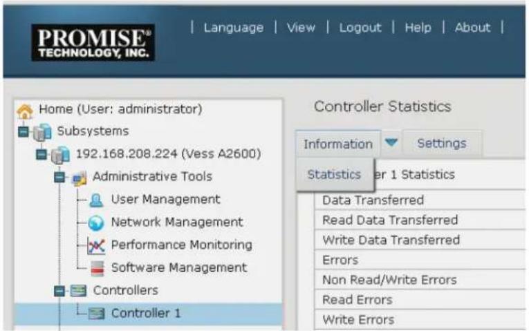
Controller statistics include:
• Data Transferred
- Read Data Transferred
- Errors
- Read Errors
- I/O Requests
- Read IO Requests
• Statistics Start Time
• Write Data Transferred
• Non-Read/Write Errors
- Write Errors
• Non-Read/Write Requests
- Write I/O Requests
• Statistics Collection Time
CONTROLLER SETTINGS
To make controller settings:
- Click the Controllers icon.
-
Click the specific Controller icon of the controller you want to manage.
-
Click the Settings tab.
-
Make settings changes as required:
-
Enter, change or delete the alias in the Alias field.
- SMART Log – Check the box to enable or uncheck to disable.
• SMART Polling Interval – Enter a value into the field, 1 to 1440 minutes - Coercion – Check the box to enable or uncheck to disable.
- Coercion Method – Choose a method from the drop-down menu:
GBTruncate
10GBTruncate
GrpRounding
TableRounding
- Write Back Cache Flush Interval – Enter a value into the field, 1 to 12 seconds.
- HDD Power Saving – Choose time periods from the drop-down menus. After an HDD has been idle for the set period of time:
Power Saving Idle Time – Parks the read/write heads.
Power Saving Standby Time – Lowers disk rotation speed.
Power Saving Stopped Time – Spins down the disk (stops rotation).
- Host Cache Flushing – Check the box to enable or uncheck to disable.
- Forced Read Ahead (cache) – Check the box to enable or uncheck to disable.
- Physical Drive Temperature Threshold - Type a temperature (50-55 °C) to trigger an event notice and email alert.
-
Physical Drive Critical Temperature Threshold - Type a temperature (58-65 °C) to trigger system shutdown.
-
Click the Submit button.
ENCLOSURES
The Enclosure menus are used to provide information for and monitor the status about the various components of the enclosure unit. Click on a specific enclosure in Tree view or in the Enclosures list to display information or settings menus for an enclosure. See the following sections:
- “Enclosure Information”
- "Enclosure temperature sensor settings"
- "Buzzer Settings"
- "Physical Drives"
LOCATE AN ENCLOSURE
To locate an enclosure in the list, click the Locate button. The LED indicators on the front panel of the enclosure will blink for one minute.
ENCLOSURE INFORMATION
The Enclosure Information read-only display menu provides key real-time information about current hardware status of the enclosure. Click on the expanders buttons to reveal current conditions and status of the enclosure, power supplies, fans, blowers, temperature sensors and voltage sensors. Move the cursor over the icons in the virtual enclosure displayed at the top of the menu to see current status and relevant conditional statistics for the fans, power supplies, and temperature sensors.
Enclosure Information display

ENCLOSURE TEMPERATURE SENSOR SETTINGS
The temperature threshold settings are used to send event notices when the internal temperature reaches a high level. To set enclosure temperature thresholds, click on the enclosure in Tree View, then click on the Settings tab to view the Enclosure Settings menu. There are two thresholds to configure:
- Controller Warning Temperature Threshold [90-95 C°] — If the enclosure temperature reaches this threshold, a warning message is sent and an event is recorded in the event log.
- Controller Critical Temperature Threshold [100-105 C°] — If the enclosure temperature reaches this threshold, a warning message is sent, an event recorded is recorded in the event log.
BUZZER SETTINGS
The audible enclosure alarm buzzer can be enabled or disabled.
To enable or disable the buzzer, click on the enclosure in Tree View, then click on the Buzzer menu expander, scroll to Settings and click the check Enable Buzzer option box. Click the Submit button.
PHYSICAL DRIVES
The Physical Drives menus are used to view information and statistics about physical hard drives installed in the enclosure and to set Global Settings for hard drives. To see the Physical Drives List, expand the individual Enclosure icon in Tree View to see the Physical Drives icon for the enclosure. To display the information for any populated slot, you can expand the Physical Drives icon in Tree View to reveal links to each slot, or click on the slot in the Physical Drives List, or click on the populated slot in the virtual enclosure displayed in the menu.
View individual physical drive information

The information listed for individual physical drives includes:
Physical Drive Information
- Physical Drive ID
- Location [Enclosure # Slot #]
- Alias
- Physical Capacity
- Configurable Capacity
• Used Capacity - Block Size [Bytes]
-
Operational Status
-
Configuration Status
- Model
- Drive Interface
- Serial Number
- Firmware Version
- Protocol Version
• Visible To [Controller #]
Advanced Physical Drive Information
• Write Cache [ Enabled/Disabled]
- Read Look Ahead Cache [ Enabled/Disabled]
- SMART Feature Set
- SMART Self Test
- SMART Error Logging
• Command Queuing Support
• Command Queuing [ Enabled/Disabled]
- Queue Depth
• Maximum Multiple DMA Mode Supported
• Maximum Ultra DMA Mode Supported
- DMA Mode
- Drive Temperature [C^/F^]
• Reference Drive Temperature
- Power Saving Mode
Disk Arrays and Logical Drives
Disk arrays and logical drives are created and managed using the Disk Arrays menu. Use the Array Configuration menu to view the Disk Array List, and to create and delete disk arrays on the enclosure. Expand the Disk Arrays icon in Tree View to view menu links for existing arrays. Each array icon can be expanded again to see the Logical Drives icon, and this can be expanded to see each logical drive icon.
For a detailed description of how to create disk arrays and logical drives using WebPAM PROe, please refer to the Quick Start Guide.
Use the top-level Disk Arrays menu to view the Disk Array List, to delete existing arrays, and to create new disk arrays using the Automatic, Express, or Advanced disk array creation menus. Note that there must be physical drives available in order to use any of the disk array creation menus.
View information for existing disk arrays by clicking on the icon in Tree View or the array name in the Disk Array List. Each individual array menu is used to create and delete logical drives, to change settings (Alias and enable/disable PDM, Media Patrol and Power Management) for the array, or to start Background Activities including PDM, Rebuild and Transition.
Individual Disk Array menu
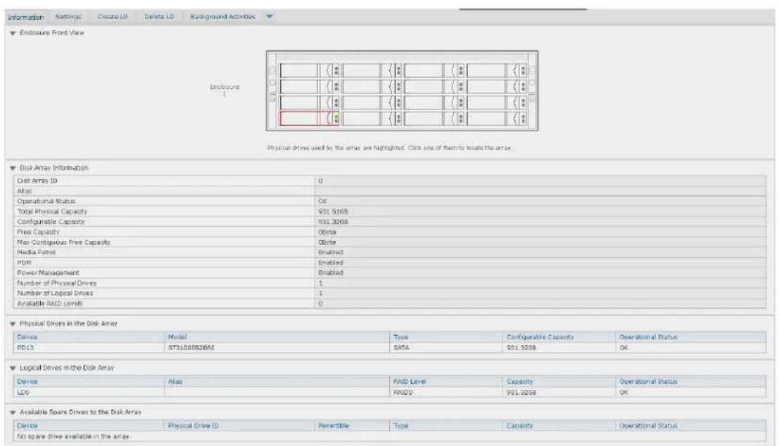
Information in the Disk Array menu includes:
- Disk Array ID [#]
- Alias
• Operational Status (see below)
• Total Physical Capacity - Configurable Capacity
• Free Capacity [Bytes]
• Max Contiguous Free Capacity [Bytes]
Other lists in this menu:
• Physical Drives in the Disk Array
• Logical Drives in the Disk Array
• Available Spare Drives to the Disk Array
• Media Patrol [ Enabled/Disabled]
- PDM [ Enabled/Disabled]
• Power Management [ Enabled/Disabled]
• Number of Physical Drives
• Number of Logical Drives
• Available RAID Levels
Disk Array Operational Status
OK – This is the normal state of a logical drive. When a logical drive is Functional, it is ready for immediate use. For RAID Levels other than RAID 0, the logical drive has full redundancy.
Synchronizing – This condition is temporary. Synchronizing is a maintenance function that verifies the integrity of data and redundancy in the logical drive. When a logical drive is Synchronizing, it will function and your data is available. However, access will be slower due to the synchronizing operation.
Critical / Degraded – This condition arises as the result of a physical drive failure. A degraded logical drive will still function and your data is still available. However, the logical drive has lost redundancy (fault tolerance). You must determine the cause of the problem and correct it.
Rebuilding – This condition is temporary. When a physical drive has been replaced, the logical drive automatically begins rebuilding in order to restore redundancy (fault tolerance). When a logical drive is rebuilding, it will function and your data is available. However, access will be slower due to the rebuilding operation.
LOGICAL DRIVE MANAGEMENT
Logical drives are made from disk arrays. In the Tree, you can see a graphic representation of the logical drives that belong to each array. The Logical Drive List can be accessed in Tree View by expanding the under Disk Arrays and clicking on the Logical Drives icon for any existing disk array, or simply click on the Logical Drive Summary icon for the Subsystem.
Click on any Logical Drive (LD) in the list to view Information and Statistics, to change Settings (Alias, Read Policy, Write Policy), to start Background Activities (Initialization, Redundancy Check), or to view the Check Table for the LD.
Information displayed in the menu includes:
- Logical Drive ID
- Alias
- Raid Level
- Operational Status
- Capacity
- Physical Capacity
• Number of Axles [#]
• Number of Used Physical Drives [#] - Stripe Size
- Sector Size [Bytes]
-
Disk Array ID
-
Read Policy
- Write Policy
- Current Write Policy
- Serial Number
- WWN
- Synchronized [Yes/No]
• Tolerable Number of Dead Drives Per Axle - Parity Pace
- Codec Scheme
SPARE DRIVES
When a physical drive in a disk array fails and a spare drive of the same type and adequate capacity is available, the disk array will begin to rebuild automatically using the spare drive.
In Tree View, click on the Spar Drive icon to see the Spare Drives List, or to create or delete an existing spare drive. Click on any spare drive in the list to information about the drive. Spare Drive Information includes:
- Spare Drive ID
- Operational Status
- Physical Drive ID
- Capacity
- Revertible [ Yes/No]
- Type
• Dedicated to Disk Arrays
RUNNING SPARE CHECK
A Spare Check verifies the operational status of your spare drives. You can also schedule a Spare Check.
To check a spare drive:
- Click the Spare Drives icon.
- Click the Spare Check tab.
- From the Physical Drive drop-down menu, choose the spare drive you want to check. Or choose All to check all the spare drives at the same time.
- Click the Submit button.
The results of the Spare Check appear under Spare Check Status in the Information tab. "Healthy" means normal condition.
LOGICAL DRIVE SUMMARY
The Logical Drive Summary displays a list of all logical drives in the Subsystem. This list does not arrange the logical drives under the disk array to which they belong nor under the enclosure in which they are located. The menu functions in the same way as the Logical Drives menu discussed in "Logical drive management" on page 102
MANAGING WITH CLU
CLU and CLI management both use a text-based terminal user interface.
In order to access the terminal program interface used for CLI and CLU management on the Vess A Class Series subsystem, insert a USB keyboard into any USB port, and connect a monitor using either the VGA or HDMI port.
USB, HDMI and VGA interfaces on rear panel
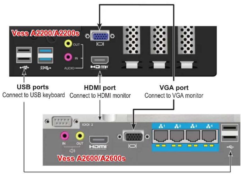
Access CLI in Windows
For Windows 7 installations, once the system has booted up it will be necessary to choose various options to complete the OS setup. You will be prompted to select a default language and other user interface preferences. Follow the instructions on screen to complete your preferences selection and to establish a user name and password for the administrator. After completing these final tasks, the Windows 7 desktop appears.

Important
DO NOT move any files from or copy any files to the PromiseApp folder on the C Drive [C:\PromiseApp] in the Windows OS.
To use the CLU interface, first open the CLI terminal interface:
- Go to Start > Run and click the Browse button.
- Navigate to the C:\PromiseApp\clitest folder.
- Click clitest.exe file then click the Open button.
- Click the OK button in the Run dialog box.
The CLI window opens. See "Using the CLU" below for instructions for instructions on how to access the CLU interface.
Access CLI Interface - Linux
After the Vess system is fully booted up, a login screen appears. Type in the default user name:
root and default password: password to continue to the desktop of the installed Linux OS.
To use the CLU interface, first follow these directions to access the PROMISE CLI Utility:
- Open a terminal window.
- Type clitest and press Enter.
The CLI runs in the terminal window. See "Using the CLU" below for instructions on how to access the CLU interface.
Using the CLU
In the CLI terminal interface, login first, then access the CLU interface. Follow the instructions below.
- At the CLI Login prompt, type the user name and press Enter.
The default user name is administrator.
- At the Password prompt, type the password and press Enter.
The default password is password.
The CLI screen appears.
- At the administrator@cli> prompt, type menu and press Enter.
The CLU Main Menu appears.
- Use the arrow keys or tab key on your keyboard to scroll the highlighted text to a command, then select or activate that command by pressing Enter.
CLU Main Menu

Notice at the bottom of the CLU interface there are on-screen reminders of keyboard actions used for CLU interface. The keyboard inputs to use the CLU are as follows:
- Arrow Keys - Use the up and down arrow keys to move the text selector, indicated by the highlighted line of text.
• Tab Key - Use the tab key to scroll down the list of text options. - Enter Key - Press the Enter key to select or activate the highlighted text action, command or option.
- CTRL + X - Press the Control key and "X" key to return to the previous menu.
- CTRL + E - Press the Control key and "E" key to bring up the Help menu
CLU notation used in this guide
The CLU command descriptions in this chapter use abbreviated descriptions of CLU navigation. It is assumed the user will understand that movement from one CLU menu item to another involves using the arrow keys to highlight the given command then pressing enter to view another list of CLU command selections or parameter options. For example, listed below are the steps used to create a new user account. Notice that Step 1 lists the path of CLU menu items to get to the Create New User menu, while Step 2 presents the various parameters to configure for the newly created user. It is implied in Step 1 that the user knows to highlight the menu item and then press the Enter key to move to the next menu item listed. This format is used throughout this chapter.
Example notation from Create New User menu item:
To create a new user account:
- Main Menu >>Additional Info and Management >> User Management >> Create New User
-
Highlight each field and type in the appropriate information:
-
User name (Maximum 31 characters. Use letters, numbers, and underscore. No spaces.)
- Password (Optional. Maximum 31 characters. Use letters, numbers, and underscore.)
• Display name (Optional) -
User's email address
-
Highlight Privilege and press the space bar to toggle though the options.
- Press Control-A to save the user.
Step 1 tells the user to start in the Main Menu, then highlight "Additional Info and Management" and press Enter; this brings up a new list of CLU menu items from which to choose "User Management" and then press Enter again bringing up another list of CLU menu items, and so on.
Use the table below for reference of the CLU interface.
| Quick Setup A sequence of steps to setup the RAID configuration. | ||
| Subsystem Management page 112 Alias | ||
| Media Patrol Start, Stop or Pause Media Patrol | ||
| Lock Management Prevent settings changes to controller for set time | ||
| Controller Management Alias, Coercion, Write Back Cache, Forced Read Ahead Cache | ||
| Enclosure Management Enclosure Status Information, Temperature & Voltage Sensor Thresholds, | ||
| Physical Drive Managementpage 123 | Physical Drive Summary | |
| Global Physical Drive Settings | WriteCached, ReadLookAhead, DMAMode,MediumErrorThreshold | |
| Disk Array Management page 128 Create | New ArrayDelete Array | |
| Spare Drive Management page 140 Create | New Spare Drive | |
| Logical Drive Management page 144 Logical Drive Summary | ||
| Network Management page 163 Network | Port Summary | |
| Background Activities page 151 Background ActivitySettings | Media Patrol, AutoRebuild, Rebuild Rate,Migration Rate, PDM Rate, Transition Rate,Sync Rate, Initialization Rate, RC Rate,ReAssigned Block Threshold, Error Block Threshold | |
| Event Viewer page 153 Runtime Events | NVRAM Events | Clear Event Statistics |
| Additional Info and Managementpage 161 | Software Management Email, Webserver, SNMP | |
| Configuration of LogsClear StatisticsRestore Factory Defaults | ||
| Buzzer page 167 Enable/Disable alarm buzzer | ||
Accessing Online Help
To access online help on any CLU screen, press Control-E.
To return to the CLU, press Enter.
Exiting the CLU
- Highlight Return to Previous Menu and press Enter.
Repeat this action until you arrive at the Main Menu.
- Main Menu, highlight Return to CLI and press Enter to exit
- Close the terminal emulation, Telnet, SSH, or terminal window.
Logging Out of the CLI
When you shut down or restart the Vess A Class Series subsystem, you are automatically logged out of the CLI.
To manually log out of the CLI (no shut down or restart):
At the username@cli> prompt, type logout and press Enter.
The prompt changes to cli>.
Logging Back Into the CLI and CLU
To log into the CLI and CLU after a manual logout:
- At the cli:> prompt, type login followed by your user name and press Enter.
- At the Password: prompt, type your password and press Enter.
- At the username@cli> prompt, type menu and press Enter to open the CLU.
MANAGING THE SUBSYSTEM (CLU)
Subsystem Management includes the following functions:
- "Making Subsystem Settings (CLU)" on page 112
- “Locking or Unlocking the Subsystem (CLU)” on page 113
Making Subsystem Settings (CLU)
An alias is optional. To set an Alias for this subsystem:
- Main Menu >> Subsystem Management >> Subsystem Settings.
- Make changes as required:
• Type and alias into the Alias field.
Maximum of 48 characters. Use letters, numbers, space between words and underscore
- Press Control-A to save your settings.
Running Media Patrol (CLU)
Media Patrol is a routine maintenance procedure that checks the magnetic media on each disk drive. Media Patrol checks all physical drives assigned to disk arrays and spare drives. It does not check unconfigured drives.
To start, stop, pause or resume Media Patrol - Main Menu >> Subsystem Management >> Media Patrol >> [Start, Stop, Pause, or Resume]. If you choose Stop, press Y to confirm.
Locking or Unlocking the Subsystem (CLU)
The lock prevents other sessions (including sessions with the same user) from making a configuration change to the controller until the lock expires or a forced unlock is done. When the user who locked the controller logs out, the lock is automatically released.
Setting the Lock
To set the lock:
- Main Menu >> Subsystem Management >> Lock Management
- In the Lock Time field, type a lock time in minutes.
1440 minutes = 24 hours
- Highlight Lock and press Enter.
Resetting the Lock
To reset the lock with a new time:
- Main Menu >> Subsystem Management >> Lock Management
- In the Lock Time field, type a lock time in minutes.
1 to 1440 minutes (24 hours)
- Highlight Renew and press Enter.
Releasing the Lock
Main Menu >> Subsystem Management >> Lock Management >> Unlock
Releasing a Lock set by another user
To release somebody else's lock:
- Main Menu >> Subsystem Management >> Lock Management >> Force Unlock
- Press the Spacebar to toggle to Yes >> Unlock
View Subsystem Date and Time (CLU)
This is a display only screen to view current Date and Time:
Main Menu >> Subsystem Management >> System Date & Time
MANAGING THE RAID CONTROLLERS (CLU)
RAID controller management includes the following functions:
- “Viewing Controller Information (CLU)” on page 115
- "Making Controller Settings (CLU)" on page 116
Viewing Controller Information (CLU)
Controller Management includes information, settings and statistics.
To access Controller Management:
- Main Menu >> Subsystem Management >> Controller Management
The Controller summary information includes:
- Alias – if assigned
- Operational Status – OK means normal. Might show BGA running. Not present indicates a malfunction or no controller is installed
-
Readiness Status – Active or Standby is normal. N/A means not accessible
-
Highlight the controller you want and press Enter.
To access additional controller information, highlight Advanced Information and press Enter.
To access controller statistics, highlight Controller Statistics and press Enter.
Clearing Statistics
To clear controller statistics, see "Clearing Statistics (CLU)" on page 165.
Making Controller Settings (CLU)
If your subsystem has two controllers, any settings you make to one controller automatically apply to the other controller.
To make Controller settings:
- Main Menu >> Subsystem Management >> Controller Management
- Highlight the controller you want and press Enter.
- Highlight Controller Settings and press Enter.
- Make the following settings as required:
• Type an alias into the Alias field.
Maximum of 48 characters. Use letters, numbers, space between words and underscore. An alias is optional.
- Highlight Coercion and press the spacebar to toggle between Enabled and Disabled.
For more information, see "Capacity Coercion".
- Highlight Coercion Method and press the spacebar to toggle through:
GB Truncate – Reduces the capacity to the nearest 1 GB boundary.
10 GB Truncate – Reduces the capacity to the nearest 10 GB boundary.
Grp (group) Rounding – Uses an algorithm to determine truncation. Results in the maximum amount of usable drive capacity.
Table Rounding - Applies a predefined table to determine truncation.
- Highlight SMART and press the spacebar to toggle between Enable and Disable.
- Highlight SMART Poll Interval and press the backspace key to erase the current value. Type a new interval value (1 to 1440 minutes).
- Highlight Poll Interval and press the backspace key to erase the current value. Type a new interval value (15 to 255 seconds).
- Highlight Adaptive Writeback Cache and press the spacebar to toggle between Enabled and Disabled.
- Highlight Forced Read Ahead Cache and press the spacebar to toggle between Enabled and Disabled.
- Highlight HDD Power Saving and the spacebar to choose a time period. After an HDD has been idle for a set period of time:
Power Saving Idle Time – Parks the read/write heads
Power Saving Standby Time – Lowers disk rotation speed
Power Saving Stopped Time – Spins down the disk (stops rotation)
You must also enable Power Management on the disk array. See “Creating a Disk Array – Advanced (CLU)” on page 131 and “Enabling Media Patrol, PDM, and Power Management on a Disk Array (CLU)” on page 136.
1. Press Control-A to save your settings.

Notes
Power Management must be enabled on the disk array for the HDD Power Saving settings to be effective. See "Making Disk Array Settings (CLU)" on page 134.
Power management is limited to the features your HDDs actually support.
MANAGING THE ENCLOSURE (CLU)
Enclosure Management includes the following functions:
- "Viewing the Enclosures Summary (CLU)" on page 118
- "Viewing Enclosure Information (CLU)" on page 119
- "Making Enclosure Settings (CLU)" on page 119
- "Viewing Power Supply Status (CLU)" on page 120
- "Viewing Cooling Unit Status (CLU)" on page 120
- "Viewing Temperature Sensor Status (CLU)" on page 121
- "Viewing Voltage Sensor Status (CLU)" on page 121
- "Locating an Enclosure (CLU)" on page 122
Viewing the Enclosures Summary (CLU)
Enclosure Management includes information, status, settings and location. To access Enclosure Management:
- Main Menu >> Subsystem Management >> Enclosure Management
The following information is shown:
• Enclosure ID number
- Enclosure Type
- Operational Status
- Status Description (specific components in need of attention, if any)
Viewing Enclosure Information (CLU)
To view enclosure information:
- Main Menu >> Subsystem Management >> Enclosure Management
- Highlight the enclosure you want and press Enter.
You can monitor power supplies, cooling units, enclosure temperatures and voltages.
Adjustable items
You can set or adjust the following items:
- Enclosure Warning and Critical temperature thresholds See "Making Enclosure Settings" below.
Making Enclosure Settings (CLU)
To make Enclosure settings:
- Main Menu >> Subsystem Management >> Enclosure Management
- Highlight the enclosure you want and press Enter.
- Highlight Enclosure Settings and press Enter.
- Highlight the Temperature Warning threshold you want to change.
- Press the backspace key to erase the current value.
- Type a new interval value in degrees C.
- Press Control-A to save your settings.
Viewing Power Supply Status (CLU)
To view the status of the power supplies:
- Main Menu >> Subsystem Management >> Enclosure Management
- Highlight the enclosure you want and press Enter.
- Highlight Power Supplies and press Enter.
The screen displays the operational and fan status of the power supply or supplies. If any status differs from normal or the fan speed is below the Healthy Threshold value, there is a fan/power supply malfunction.
Viewing Cooling Unit Status (CLU)
To display the status of the power supply fans:
Main Menu >>Subsystem Management >> Enclosure Management
This is a read-only menu. The screen displays the status and speed of cooling units. If fan speed is below the Healthy Threshold, there is a malfunction.
Viewing Temperature Sensor Status (CLU)
To display the status of the temperature sensors:
Main Menu >> Subsystem Management >> Enclosure Management
This is a read-only menu. If any temperature exceeds the Healthy Threshold value, there is an overheat condition in the enclosure.
Viewing Voltage Sensor Status (CLU)
To display the status of the voltage sensors:
Main Menu >>Subsystem Management >> Enclosure Management
This is a read-only menu. If any voltage is outside the Healthy Threshold values, there is a voltage malfunction in the enclosure.
Locating an Enclosure (CLU)
This feature helps you identify the physical Vess A Class Series enclosure you are working with through the CLU.
- Main Menu >> Subsystem Management >> Enclosure Management and press Enter.
- Highlight the enclosure you want and press Enter.
- Highlight Locate Enclosure and press Enter.
The LEDs on the front of the Vess A Class Series blink for one minute.
PHYSICAL DRIVE MANAGEMENT (CLU)
Physical Drive Management includes the following functions:
- "Viewing a List of Physical Drives (CLU)" on page 123
- "Making Global Physical Drive Settings (CLU)" on page 124
- "Viewing Physical Drive Information (CLU)" on page 125
- "Setting an Alias (CLU)" on page 126
- "Locating a Physical Drive (CLU)" on page 126
Viewing a List of Physical Drives (CLU)
To view a list of physical drives:
Main Menu >> Physical Drive Management
The list of physical drives displays.
Making Global Physical Drive Settings (CLU)
All physical drive settings are made globally, except for setting an alias, which applies to individual drives.
To make global physical drive settings:
- Main Menu >> Physical Drive Management >> Global Physical Drives Settings
-
Change the following settings as required.
-
Highlight Write Cache and press the spacebar to toggle between Enabled and Disabled.
- Highlight Read Look Ahead Cache and press the spacebar to toggle between Enabled and Disabled.
- Highlight MediumErrorThreshold and press the backspace key to remove the current value, then type a new smaller value.
-
Highlight DMA Mode and press the spacebar to toggle through UDMA 0 to 6 and MDMA 0 to 2.
-
Press Control-A to save your settings.
See "Viewing Physical Drive Information" below to determine which functions your physical drives support.
Medium Error Threshold is the number of bad blocks tolerated before the controller marks the drive as Dead. The default setting is 64 blocks. A setting of zero disables the function. When disabled, no drives are marked offline even when errors are detected.
Viewing Physical Drive Information (CLU)
To view information about a physical drive:
-
Main Menu >> Physical Drive Management
-
Highlight the physical drive you want and press Enter.
Basic information displays.
- Highlight Advanced Information and press Enter.
Advanced information displays.
Viewing Physical Drive Statistics (CLU)
To view the statistics for the selected physical drive:
- Main Menu >> Physical Drive Management
- Highlight the physical drive you want and press Enter.
- Highlight Physical Drive Statistics and press Enter.
Clearing Statistics
To clear physical drive statistics, see "Clearing Statistics (CLU)" on page 165.
Setting an Alias (CLU)
An alias is optional. To set an Alias for a physical drive:
- Main Menu >> Physical Drive Management
- Highlight the physical drive you want and press Enter.
- Type an alias into the field provided.
Maximum of 32 characters. Use letters, numbers, spaces and underscores.
- Press Control-A to save your settings.
Locating a Physical Drive (CLU)
This feature helps you identify a physical drive within the Vess A Class Series enclosure you are working with through the CLU. To locate a physical drive:
- Main Menu >> Physical Drive Management
- Highlight the physical drive you want and press Enter.
- Highlight Locate Physical Drive and press Enter.
The drive carrier status LED flashes for one minute. See the illustrations on next page.
Vess A2600/A2600s Front Left side (all drive carriers have status and activity LEDs)

Vess A2200/2200s Left panel LED
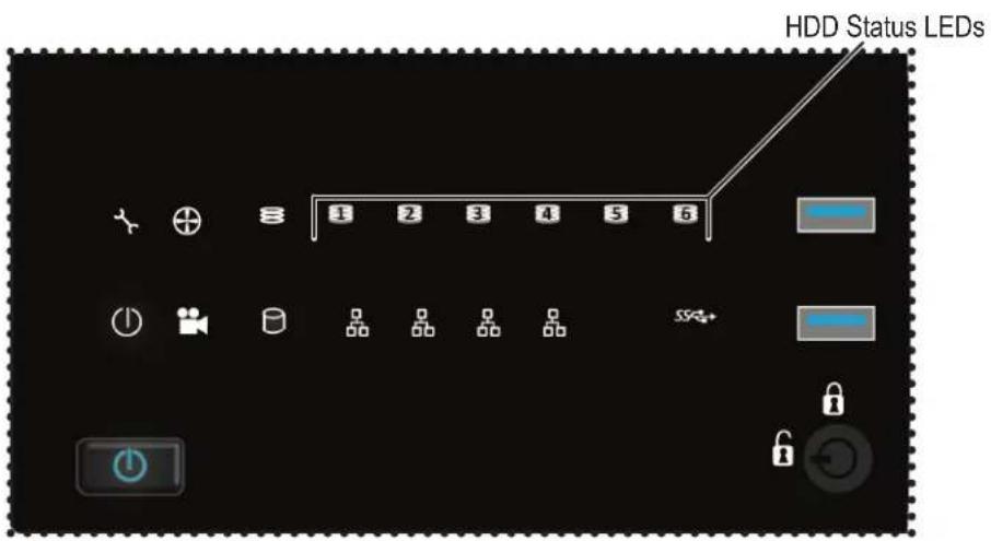
MANAGING DISK ARRAYS (CLU)
Disk Array Management includes the following functions:
- "Viewing a List of Disk Arrays (CLU)" on page 128
- “Creating a Disk Array (CLU)” on page 129
- "Deleting a Disk Array (CLU)" on page 133
- "Making Disk Array Settings (CLU)" on page 134
- "Viewing Disk Array Information (CLU)" on page 135
- “Enabling Media Patrol, PDM, and Power Management on a Disk Array (CLU)” on page 136
- “Rebuilding a Disk Array (CLU)” on page 137
- "Running Media Patrol on a Disk Array (CLU)" on page 137
- "Locating a Disk Array (CLU)" on page 139
Viewing a List of Disk Arrays (CLU)
To view a list of disk arrays:
Main Menu >> Disk Array Management
The list of disk arrays displays.
Creating a Disk Array (CLU)
The CLU provides three methods of creating a disk array:
- Automatic – Creates a new disk array following a default set of parameters. Creates a hot spare drive for all RAID levels except RAID 0, when five or more unconfigured physical drives are available. You can accept or reject the proposed arrangement but you cannot modify it. See “Creating a Disk Array – Automatic”
- Express – You choose the parameters for a new disk array by specifying the characteristics you want. You can create multiple logical drives at the same time, however they are all identical. Creates a hot spare drive for all RAID levels except RAID 0. See “Creating a Disk Array – Express”
- Advanced – Enables you to specify all parameters for a new disk array, logical drives and spare drives. See “Creating a Disk Array – Advanced”
Creating a Disk Array – Automatic (CLU)
To create a disk array using the Automatic feature:
- Main Menu >> Disk Array Management >> Create New Array >> Configuration Method
- Press the spacebar to toggle to Automatic.
- Press Control-A to save your settings and move to the next screen.
- Review the proposed configuration of disk array and logical drives.
- To accept the proposed configuration and create the disk array and logical drives, highlight Save settings and Continue and press Enter.
- To reject the proposed configuration, highlight Return to previous menu and press Enter. You return to the Disk Arrays Summary screen.
To create a disk array with different characteristics, repeat the steps above specifying different parameters but choose the Express or Advanced option.
Creating a Disk Array – Express (CLU)
To create a disk array using the Express feature:
-
Main Menu >> Disk Array Management >> Create New Array >> Configuration Method and press the spacebar to toggle to Express.
-
Highlight the following options and press to spacebar to choose Yes or No:
-
Redundancy
- Capacity
- Performance
-
Spare Drive
-
Highlight Number of Logical Drives and press the backspace key to erase the current value, then enter the number of logical drives you want.
-
Highlight Application Type and press the spacebar to toggle though the applications and choose the best one for your disk array.
-
File Server
- Video Stream
- Transaction Data
- Transaction Log
-
Other
-
Press Control-A to save your settings and move to the next screen.
-
Review the proposed configuration of disk array and logical drives.
To accept the proposed configuration and create the disk array and logical drives, highlight Save Configuration and press Enter.
To reject the proposed configuration, highlight Return to previous menu and press Enter.
You return to the Disk Arrays Summary screen.
To create a disk array with different characteristics, highlight Create New Array and press Enter. Repeat the steps above specifying different parameters. Or choose the Advanced option.
Creating a Disk Array – Advanced (CLU)
To create a disk array using the Advanced feature:
- Main Menu >> Disk Array Management >> Create New Array
- Highlight Configuration Method and press the spacebar to toggle to Advanced.
Step 1 – Disk Array Creation
- If you want to specify an alias to the disk array, highlight Alias and type a name.
Maximum of 32 characters (letters, numbers, spaces and underscores). - Choose whether to enable Media Patrol, PDM, and Power Management.
- Choose a Media Type, HDD or SSD.
- Highlight Save Settings and Continue and press Enter.
Step 2 – Select Physical Drives
-
Highlight a physical drive you want to add to your array and press the spacebar to choose it.
Repeat this action until you have selected all the physical drives for your array. -
Highlight Save Settings and Continue and press Enter.
Step 3 – Logical Drive Creation
- If you want to specify an alias to the logical drive, highlight Alias and type a name.
Maximum of 32 characters (letters, numbers, spaces and underscores).
- Highlight RAID Level and press the spacebar to toggle though a list of available RAID levels.
- If you want to create multiple logical drives, highlight Capacity, press the backspace key to remove the current value, then type a new smaller value.
- RAID 30, 50 and 60 only. Highlight Number of Axles and press the spacebar to choose the number of axles.
-
For the following items, accept the default value or highlight and press the spacebar to choose a new value:
-
Highlight Stripe and press the spacebar to toggle through stripe sizes and choose 64 KB, 128 KB, 256 KB, 512 KB, or 1 MB.
- Highlight Sector and press the spacebar to toggle through sector sizes and choose 512 B, 1 KB, 2 KB, or 4 KB.
- Highlight Write Policy and press the spacebar to toggle write cache policy between WriteBack and WriteThru (write through).
-
Highlight Read Policy and press the spacebar to toggle read cache policy though [ReadCache, ReadAhead, and NoCache].
-
Highlight Save Logical Drive and press Enter.
Step 4 – Summary
Review logical drives you are about to create for your new array. Then do one of the following actions:
- If you agree with the logical drives as specified, highlight Complete Disk Array Creation and press Enter.
- If you specified less than the full capacity for the logical drive in the previous screen, and you want to add another logical drive now, highlight Create New Logical Drive and press Enter.
- If you do not agree with the logical drives, highlight Return to Previous Screen and press Enter to begin the process again.
Deleting a Disk Array (CLU)

Caution
When you delete a disk array, you delete all the logical drives and the data they contain. Back up all important data before deleting a disk array.
- Main Menu >> Disk Array Management and press Enter.
- Highlight the disk array you want to delete and press the spacebar to mark it.
The mark is an asterisk (*) to the left of the listing.
- Highlight Delete Marked Arrays and press Enter.
- Press Y to confirm the deletion.
- Press Y again to reconfirm.
Making Disk Array Settings (CLU)
To make disk array settings:
- Main Menu >> Disk Array Management
The list of disk arrays appears.
- Highlight the disk array you want and press the Enter.
-
Make settings changes as required:
-
Enter, change or delete the alias in the Alias field Maximum of 32 characters (letters, numbers, spaces, and underscores).
- Media Patrol – Highlight and press the spacebar to toggle between enable and disable.
- PDM – Highlight and press the spacebar to toggle between enable and disable.
-
Power Management – Highlight and press the spacebar to toggle between enable and disable.
-
Press Control-A to save your settings.

Notes
You can also enable or disable Media Patrol for the entire RAID system.
Power Management must be enabled on the disk array for the HDD Power Saving settings to be effective.
Power management is limited to the features your HDDs actually support.
Viewing Disk Array Information (CLU)
-
Main Menu >> Disk Array Management
-
Highlight the disk array you want and press Enter.
The information and settings screen appears.
- Highlight any of the following and press Enter to view a list of:
• Physical drives in this array
• Logical drives in this array
- Spare drives of the disk array
Enabling Media Patrol, PDM, and Power Management on a Disk Array (CLU)
Media Patrol checks the magnetic media on physical drives. Predictive Data Migration (PDM) migrates data from the suspect physical drive to a spare drive before the physical drive fails. Power Management parks the heads, spins down, and stops rotation after a set period of time to reduce power consumption.
Media Patrol, PDM, and Power Management are enabled by default. Enabled is the recommended setting for both features.
To enable Media Patrol, PDM, and Power Management on a disk array:
- Main Menu >> Disk Array Management
- Highlight the disk array you want and press Enter.
- Highlight Media Patrol and press the spacebar to toggle between Enable and Disable.
- Highlight PDM and press the spacebar to toggle between Enable and Disable.
- Highlight Power Management and press the spacebar to toggle between Enable and Disable.
- Press Control-A to save your settings.
Rebuilding a Disk Array (CLU)
Before you can rebuild, you must have a replacement or target physical drive of adequate capacity for your disk array.
To rebuild a disk array:
- Main Menu >> Disk Array Management
- Highlight the disk array you want and press Enter.
- Highlight Background Activities >> Rebuild
Default source and target drives are shown with possible alternative choices.
-
To choose different drive, highlight the drive, press the backspace key to remove the current number, then type a new number.
-
Highlight Start and press Enter.
Running Media Patrol on a Disk Array (CLU)
Media Patrol is a routine maintenance procedure that checks the magnetic media on each disk drive. If Media Patrol encounters a critical error, it triggers PDM if PDM is enabled on the disk array.
Running PDM on a Disk Array (CLU)
Predictive Data Migration (PDM) migrates data from the suspect physical drive to a spare drive before the physical drive fails.
Before you can run PDM, you must have a replacement or target physical drive of adequate capacity for your disk array.
To run PDM on a disk array:
- Main Menu >> Disk Array Management
- Highlight the disk array you want and press Enter.
- Highlight Background Activities >> Predictive Data Migration and press Enter.
Default source and target drives are shown with possible alternative choices. - To choose different drive, highlight the drive, press the backspace key to remove the current number, then type a new number.
- Highlight Start and press Enter.
See "Enabling Media Patrol, PDM, and Power Management on a Disk Array (CLU)" on page 136. For PDM rate, see "Making Background Activity Settings (CLU)" on page 152.
Running Transition on a Disk Array (CLU)
Transition is the process of replacing a revertible spare drive that is currently part of a disk array with an unconfigured physical drive or a non-revertible spare drive.
In order to run Transition:
• The spare drive must be Revertible.
- You must have an unconfigured physical drive of the same or larger capacity to replace the spare drive.
To run Transition on a disk array:
- Main Menu >> Disk Array Management
- Highlight the disk array you want and press Enter.
- Highlight Background Activities >> Transition
Default source and target drives are shown with possible alternative choices.
- To choose different drive, highlight the drive, press the backspace key to remove the current number, then type a new number.
- Highlight Start and press Enter.
For transition rate, see "Making Background Activity Settings (CLU)" on page 152.
Locating a Disk Array (CLU)
This feature helps you identify the physical drives assigned to the disk array you are working with in the CLU.
To locate a disk array:
- Main Menu >> Disk Array Management
- Highlight the disk array you want and press Enter.
- Highlight Locate Disk Array and press Enter. The drive carrier status LEDs flash for one minute.
MANAGING SPARE DRIVES (CLU)
Spare Drive Management includes the following functions:
- "Viewing a list of Spare Drives (CLU)" on page 140
- “Creating a Spare Drive (CLU)” on page 141
- “Running Redundancy Check (CLU)” on page 150
- "Deleting a Spare Drive (CLU)" on page 143
Viewing a list of Spare Drives (CLU)
To view a list of spare drives:
Main Menu >> Spare Drive Management
A list of the current spare drives appears, including the following parameters:
• ID number
• Operational Status
• Physical Drive ID number
- Configured Capacity
- Revertible – The spare drive returns to spare status after you replace the failed drive in the disk array.
- Type – Global (all disk arrays) or Dedicated (to specified disk arrays)
• Dedicated to Array – The array to which a dedicated spare is assigned
Creating a Spare Drive (CLU)
Only unconfigured physical drives can be used to make spares. Check your available drives under Physical Drive Management. See "Physical Drive Management (CLU)" on page 123.
- Main Menu >> Spare Drive Management >> Create New Spare Drive
A default physical drive is shown with possible alternative choices.
-
To choose different drive, highlight the drive, press the backspace key to remove the current number, then type a new number.
-
Highlight Revertible and press the spacebar to toggle between Yes and No.
A revertible drive can be returned to spare status after you replace the failed drive in a disk array.
- Highlight Spare Type and press the spacebar to toggle between Dedicated and Global.
Dedicated means this spare drive can only be used with the specified disk arrays. Global means this spare drive can be used by any disk array.
If you chose Dedicated, a default disk array is shown with possible alternative choices.
To choose different array, highlight the array and press the backspace key to erase the current number, then type the new number.
- Press Control-A to save the spare drive.
Making Spare Drive Settings (CLU)
To change spare drive settings:
- Main Menu >> Spare Drive Management
A list of the current spare drives appears, including the following parameters:
- Highlight the spare drive you want to change and press Enter.
-
Highlight the setting you want to change:
-
Revertible – A revertible drive can be returned to spare status after you replace the failed drive in a disk array.
-
Type – Dedicated means this spare drive can only be used with the specified disk arrays. Global means this spare drive can be used by any disk array.
-
Press the spacebar to toggle between the choices.
- For dedicated spares, type the array number the spare is assigned to.
- Press Control-A to save your settings.
Running Spare Check (CLU)
To run Spare Check:
- Main Menu >> Spare Drive Management
A list of the current spare drives appears.
- Highlight the spare drive you want to check and press Enter.
- Highlight Start Spare Check and press Enter.
The results appear next to Spare Check Status in the same window. Healthy means normal.
Deleting a Spare Drive (CLU)

Caution
If the spare drive you delete is the only spare, the controller does not rebuild a critical array until you provide a new spare drive.
To delete a spare drive:
- Main Menu >> Spare Drive Management
A list of the current spare drives appears.
- Highlight the spare drive you want to delete and press the spacebar to mark it.
The mark is an asterisk (*) to the left of the listing.
-
Highlight Delete Marked Spare Drives and press Enter.
-
Press Y to confirm the deletion.
MANAGING LOGICAL DRIVES (CLU)
Logical drive management includes:
- "Creating a Logical Drive (CLU)" on page 144
- "Deleting a Logical Drive (CLU)" on page 146
- "Viewing the Logical Drive Check Table (CLU)" on page 148
- "Making Logical Drive Settings (CLU)" on page 148
- "Initializing a Logical Drive (CLU)" on page 149
- "Running Redundancy Check (CLU)" on page 150
- "Locating a Logical Drive (CLU)" on page 150
Creating a Logical Drive (CLU)
You can create logical drives on existing disk arrays if there is available space in the array.
To create a logical drive from an existing disk array:
- Main Menu >> Disk Array Management
- Highlight the disk array in which you want to create a logical drive and press Enter.
- Logical Drives in the Disk Array >> Create New Logical Drive
The Disk Array ID number and Maximum capacity available for the new logical drive are displayed.
-
Highlight the following parameters and press the backspace key to erase the current value:
-
Alias – Type an alias into the field, if desired. Maximum of 32 characters (letters, numbers, spaces and underscore).
- RAID Level - Press the spacebar to toggle though a list of available RAID levels.
-
Capacity – Maximum capacity shown. Enter a smaller capacity if desired.
-
Highlight the following parameters and press the spacebar to toggle though the available choices:
-
Stripe size – Press the spacebar to choose: 64 KB, 128 KB, 256 KB, 512 KB, or 1 MB.
- Sector size – Press the spacebar to choose: 512 B; 1 KB, 2 KB, or 4 KB.
- Write Policy – Press spacebar to choose: Write Back or Write Through.
-
Read Policy – Press spacebar to choose: No Cache, Read Cache, or Read Ahead Cache.
-
RAID 30, 50 and 60 only. Highlight Number of Axles and press the spacebar to choose the number of axles.
- Highlight Save Logical Drive and press Enter.

Note
If you did not use all of the available capacity of the disk array, you can create an additional logical drive at this point.
Deleting a Logical Drive (CLU)

Caution
When you delete a logical drive, you delete all the data it contains. Back up all important data before deleting a logical drive.
To delete a logical drive from a disk array:
- Main Menu >> Disk Array Management
- Highlight the disk array that contains the logical drive you want to delete and press Enter.
- Highlight Logical Drives in the Disk Array and press Enter.
- Highlight the logical drive you want to delete and press the spacebar to mark it.
The mark is an asterisk (*) to the left of the listing.
-
Highlight Delete Marked Logical Drives and press Enter.
-
Press Y to confirm the deletion.
Press Y again to re-confirm.
Viewing Logical Drive Information (CLU)
To view logical drive information:
-
Main Menu >> Logical Drive Management
-
Highlight the logical drive you want and press Enter.
The information and settings screen appears.
-
Highlight any of the following and press Enter to view more information:
-
Check Table – Read Check, Write Check, and Inconsistency Check Tables
• Logical Drive Statistics
• Background Activities - Locate Logical Drive
Viewing Logical Drive Statistics (CLU)
To view logical drive information:
- Main Menu >> Logical Drive Management
- Highlight the logical drive you want and press Enter.
The information and settings screen appears.
- Highlight Logical Drive Statistics and press Enter.
The statistics screen appears.
To clear logical drive statistics, see "Clearing Statistics (CLU)" on page 165.
Viewing the Logical Drive Check Table (CLU)
To view logical drive information:
- Main Menu >> Logical Drive Management
- Highlight the logical drive you want and press Enter.
- Highlight Check Table and press Enter.
- Highlight one of the following options and press Enter:
• Show All Records
- Read Check Table
• Write Check Table
• Inconsistent Check Table
Making Logical Drive Settings (CLU)
To make Logical Drive settings:
- Main Menu >> Logical Drive Management
- Highlight the logical drive you want and press Enter.
-
For the following items, accept the existing setting choose a new one:
-
Highlight Alias and type an alias into the field provided.
- Maximum of 32 characters (letters, numbers, spaces and underscores). An alias is optional.
- Highlight WritePolicy and press the spacebar to toggle between WriteBack and WriteThru (write though).
-
Highlight ReadPolicy and press the spacebar to toggle though ReadCache, ReadAhead and None.
-
Press Control-A to save your settings.
Initializing a Logical Drive (CLU)
This function sets all data bits in the logical drive to zero.

Warning
When you initialize a logical drive, all the data on the logical drive is lost. Backup any important data before you initialize a logical drive.
To initialize a logical drive:
- Main Menu >> Logical Drive Management and press Enter.
- Highlight the logical drive you want and press Enter.
- Highlight Background Activities >> Start Initialization
The initialization parameters appear.
- Initialization pattern – The default 00000000 is best for most applications
- Quick Initialization – Yes means only the first and last sections of the logical drives are initialized. No means the entire logical drive is initialized.
To change a parameter, highlight it and press the backspace key to erase the current value, then type the new value.
- Highlight Start and press Enter.
If necessary, you can pause and resume or stop and restart the Initialization. You cannot access the logical drive until Initialization has finished.
For initialization rate, see "Making Background Activity Settings (CLU)" on page 152.
Running Redundancy Check (CLU)
Redundancy Check is a maintenance procedure for logical drives in fault-tolerant disk arrays that ensures all the data matches exactly.
To run Redundancy Check:
- Main Menu >> Logical Drive Management
- Highlight the logical drive you want and press Enter.
- Highlight Background Activities >> Start Redundancy Check
The redundancy check parameters appear.
- Auto Fix – Corrects inconsistencies automatically
- Pause On Error – Pauses the Redundancy Check when an error is found
To change a parameter, highlight it and press the backspace toggle between Yes and No.
- Highlight Start and press Enter.
If necessary, you can pause and resume or stop and restart the Redundancy Check. You can use the logical drive while Redundancy Check is running.
For Redundancy Check rate, see "Making Background Activity Settings (CLU)" on page 152.
Locating a Logical Drive (CLU)
This feature helps you identify the physical drives assigned to the logical drive you are working with in the CLU. To locate a logical drive:
- Main Menu >> Logical Drive Management
- Highlight the logical drive you want and press Enter.
- Highlight Locate Logical Drive and press Enter.
The drive carrier status LEDs flash for one minute.
MANAGING BACKGROUND ACTIVITY (CLU)
Background activity refers to any of several functions that take place in the background while normal operation of the Vess A Class Series continues.
Background activities work in conjunction with disk arrays and logical drives. See "Managing Disk Arrays (CLU)" on page 128 and "Managing Logical Drives (CLU)" on page 144 for more information about how and when to use background activities.
Background Activity Management includes the following functions:
- "Viewing Current Background Activities (CLU)" on page 151
- “Making Background Activity Settings (CLU)” on page 152
Viewing Current Background Activities (CLU)
Main Menu >> Background Activities
A count of current background activities appears, including:
- Rebuild
• PDM (Predictive Data Migration) - Synchronization
- Redundancy Check
- Transition
- Initialization
• Media Patrol
Making Background Activity Settings (CLU)
- Main Menu >> Background Activities >> Background Activity Settings
- Highlight following and press the spacebar to toggle between Enabled and Disabled.
• Media Patrol – Checks the magnetic media on physical drives
- Auto Rebuild – When enabled and no spare drive is available, the disk array begins to rebuild as soon as you replace the failed physical drive with an unconfigured physical drive of equal or greater size
-
Highlight following and press the spacebar to toggle through Low, Medium, and High rates:
-
Rebuild – Rebuilds data to a replacement physical drive in a disk array
- PDM – Migrates data from a suspect physical drive to a replacement drive in a disk array
• Transition – Returns a revertible spare drive to spare status - Synchronization – Checks the data integrity on disk arrays
- Initialization – Full initialization sets all data bits in the logical drive to a specified pattern, such as all zeros
- Redundancy Check – Checks, reports and can correct data inconsistencies in logical drives
The rates are defined as follows:
- Low – Fewer resources to activity, more to data read/write.
• Medium – Balance of resources to activity and data read/write. -
High – More resources to activity, fewer to data read/write.
-
Press Control-A to save your settings.
WORKING WITH THE EVENT VIEWER (CLU)
Working with the Event Viewer includes the following functions:
- “Clearing Runtime Events (CLU)” on page 154
- “Clearing NVRAM Events (CLU)” on page 155
The Event Viewer displays log of subsystem events. Events are classified as:
- Runtime Events – A list of and information about the 1023 most recent runtime events recorded since the subsystem was started
- NVRAM Events – A list of and information about the most important events over multiple subsystem startups. NVRAM events are stored in non-volatile memory
| Event Severity Levels | |
| Level Description | |
| Fatal Non-recoverable error or failure has occurred. | |
| Critical Action is needed now and the implications of the condition are serious. | |
| Major Action is needed now. | |
| Minor Action is needed but the condition is not a serious at this time. | |
| Warning User can decide whether or not action is required. | |
| Information Information only, no action is required. | |
Viewing Runtime Events (CLU)
To display Runtime Events:
1. Main Menu >> Event Viewer
The log of Runtime Events appears. Events are added to the top of the list. Each item includes:
- Sequence number – Begins with 0 at system startup.
• Device – Disk Array, Logical Drive, Physical Drive by its ID number. - Severity – See the table above.
- Timestamp – Date and time the event happened.
-
Description – A description of the event in plain language.
-
Press the up and down arrow keys to scroll through the log.
Clearing Runtime Events (CLU)
To clear the Runtime Event log:
- Main Menu >> Event Viewer >> Clear Runtime Event Log
- Press Y to confirm.
Viewing NVRAM Events (CLU)
This screen displays a list of and information about the most important events over multiple subsystem startups.
To display NVRAM events:
- Main Menu >> Event Viewer >> NVRAM Events
The log of NVRAM Events appears. Events are added to the top of the list. Each item includes:
- Sequence number – Begins with 0 at system startup.
• Device – Disk Array, Logical Drive, Physical Drive by its ID number. - Severity – See the table on the previous page.
- Timestamp – Date and time the event happened.
-
Description – A description of the event in plain language.
-
Press the up and down arrow keys to scroll through the log.
Clearing NVRAM Events (CLU)
To clear the Runtime Event log:
- Main Menu >> Event Viewer >> NVRAM Events >> Clear NVRAM Event Log
- Press Y to confirm.
MANAGING USERS (CLU)
User Management includes the following functions:
- "Viewing User Information (CLU)" on page 156
- "Creating a User (CLU)" on page 157
- "Changing User Settings (CLU)" on page 158
- “Changing User Password (CLU)” on page 159
- "Deleting a User (CLU)" on page 160
Viewing User Information (CLU)
Each user types their user name and password to log into the CLI.
To view a list of current user accounts:
- Main Menu >> Additional Info and Management >> User Management
A list of the current users appears.
Creating a User (CLU)
To create a new user account:
-
Main Menu >> Additional Info and Management >> User Management >> Create New User
-
Highlight each field and type in the appropriate information:
-
User name (Maximum 31 characters; use letters, numbers, and underscores. No spaces.)
- Password (Optional. Maximum 31 characters. Use letters, numbers, and underscore.)
• Display name (Optional) -
User's email address
-
Highlight Privilege and press the space bar to toggle though the options.
See the Table on the next page.
- Press Control-A to save the user.
| User Privileges | |
| Level Meaning | |
| View | Allows the user to see all status and settings but not to make any changes |
| Maintenance | Allows the user to perform maintenance tasks including Rebuilding, PDM, Media Patrol, and Redundancy Check |
| Power | Allows the user to create (but not delete) disk arrays and logical drives, change RAID levels, change stripe size; change settings of components such as disk arrays, logical drives, physical drives, and the controller |
| Super | Allows the user full access to all functions including create and delete users and changing the settings of other users, and delete disk arrays and logical drives.The default “administrator” account is a Super User |
Changing User Settings (CLU)
The Administrator or a Super User can change other users' settings.
To change user settings:
- Main Menu >> Additional Info and Management >> User Management
- Highlight the User whose settings you want to change and press Enter.
- Highlight Privilege and press the space bar to toggle though the options.
See the Table above.
- Highlight Status and press the space bar to toggle between Enabled and Disabled.
- Highlight the items you want and press the backspace key to erase the current value, then
type the new value:
- User name
-
Email address
-
Press Control-A to save the settings.

Important
If a user is logged-in when his account is disabled, the user is immediately logged-out.
Changing User Password (CLU)
The Administrator or a Super User can change other users' passwords.
To change a password:
- Main Menu >> Additional Info and Management >> User Management
- Highlight the User whose password you want to change and press Enter.
- Highlight Change Password... and press Enter.
- Highlight New Password and type a new password.
Maximum 31 characters. Use letters, numbers, and underscore.
- Highlight Retype Password and type the new password again to verify.
- Press Control-A to save the new password.

Note
To reset the Administrator's password to the factory default, see "Restoring Factory Defaults (CLU)" on page 166.
Deleting a User (CLU)
The Administrator or a Super User can delete other users. You cannot delete the account you used to log in. There must always be one Super User account.
Rather than deleting a user, consider disabling a user account.
To delete a user:
- Log in under a user name other than the one you want to delete.
- Main Menu >> Additional Info and Management >> User Management
- Highlight the user you want to delete and press the spacebar to mark it.
The mark is an asterisk (*) to the left of the listing.
-
Highlight Delete Marked Users and press Enter.
-
Press Y to confirm the deletion.
SOFTWARE MANAGEMENT (CLU)
Software Management includes the following functions:
- "Email Settings (CLU)" on page 161
- "SLP Settings (CLU)" on page 162
- "Web Server Settings (CLU)" on page 162
Email Settings (CLU)
By default, Email service is set to Automatic and its normal status is Started.
To make Email service settings:
- Main Menu >> Additional Info and Management >> Software Management >> Email
Startup Type
- Press the spacebar to toggle between Automatic and Manual.
-
Highlight the following and press the backspace key to erase the current value, then type the new value:
-
SMTP server IP address or server name
• Server Port number (25 is the default) -
Highlight Authentication and press the spacebar to toggle between Yes and No.
If you selected Yes, type in a User name and Password in the fields provided.
-
The following items are optional but recommended. Highlight and press the backspace key to erase the current value, then type the new value:
-
Sender's email address
-
Subject Line for the email message
-
Press Control-A to save your settings.
To start, stop or restart the Email service, highlight Start, Stop or Restart and press Enter.
SLP Settings (CLU)

Note
SLP is supported on the Linux OS version only.
By default, SLP service is set to Automatic and its normal status is Started.
To make SLP service settings:
- Main Menu >> Additional Info and Management >> Software Management >> SLP
Startup Type
- Press the spacebar to toggle between Automatic and Manual.
- Press Control-A to save your settings.
To start, stop or restart the SLP service, highlight Start, Stop, or Restart and press Enter.
Web Server Settings (CLU)
By default, Web Server service is set to Automatic and its normal status is Started.
To make Web Server service settings:
-
Main Menu >> Additional Info and Management >> Software Management >> Startup Type
-
Press the spacebar to toggle between Automatic and Manual.
-
Highlight the following and press the backspace key to erase the current value, then type the new value:
-
HTTP Port (8090 is the default)
-
Session Time Out (24 minutes is the default. 1440 minutes = 24 hours)
-
Highlight SSL and press the spacebar to toggle between Enabled and Disabled.
-
Highlight HTTPS Port and press the backspace key to erase the current value, then type the new value. 443 is the default.
-
Press Control-A to save your settings.
To start, stop or restart the service, highlight Start, Stop, or Restart and press Enter.
SNMP Settings (CLU)
By default, Simple Network Management Protocol (SNMP) service is set to Automatic and its normal status is Started.
To make SNMP service settings:
- Main Menu >> Additional Info and Management >> Software Management >> SNMP
Startup Type
- Press the spacebar to toggle between Automatic and Manual.
- Highlight the following and press the backspace key to erase the current value, then type the new value:
• Port Number – 161 is the default
- System Name – (optional) Type a system name in this field
- System Location – Type a country name in this field
- System Contact – Type the email address of your system administrator in this field
- Read Community – Type a community name in this field
- Press Control-A to save your settings.
To start, stop or restart the SNMP service, highlight Start, Stop, or Restart and press Enter.
Managing SNMP Trap Sinks (CLU)
Viewing a List of Trap Sinks
To create a trap sink:
- Main Menu >> Additional Info and Management >> Software Management >> SNMP
Trap Sinks
A list of the current trap sinks appears.
Adding a Trap Sink
To add a trap sink:
-
Main Menu >> Additional Info and Management >> Software Management >> SNMP
Trap Sinks >> Create New Trap Sink >> Trap Sink IP address
-
Press the backspace key to erase the current value, then type the new IP address in this field.
-
Highlight Trap Filter and press the spacebar to toggle through the severity levels.
See the Table below.
- Press Control-A to save the Trap Sink.
| Event Severity Levels | |
| Level Description | |
| Fatal Non-recoverable error or failure has occurred. | |
| Critical Action is needed now and the implications of the condition are serious. | |
| Major Action is needed now. | |
| Minor Action is needed but the condition is not a serious at this time. | |
| Warning User can decide whether or not action is required. | |
| Information Information only, no action is required. | |
Deleting a Trap Sink
To delete a trap sink:
- Main Menu >> Additional Info and Management >> Software Management >> SNMP
Trap Sinks
CLEARING STATISTICS (CLU)
This function clears the statistical counts for the RAID controller, iSCSI ports, physical drives, and logical drives. To clear statistics:
- Main Menu >> Additional Info and Management >> Clear Statistics
- Press Y to confirm the deletion.
RESTORING FACTORY DEFAULTS (CLU)
This function restores the factory default settings to the firmware and software items you select.

Caution
Restoring default settings can disrupt your Vess Class A Series functions. Use this feature only when necessary
- Main Menu >> Additional Info and Management >> Restore Factory Defaults
- Highlight the setting groups you want to restore and press the spacebar to toggle between Yes and No.
"Yes" means this setting is restored to the default value.
"No" means the current setting remains untouched.
- Highlight Restore Factory Defaults and press Enter.
- Press Y to confirm the reset.
BUZZER
Making Buzzer Settings
The buzzer sounds to inform you that the Vess A Class Series needs attention.
To make buzzer settings:
- Main Menu >> Buzzer
A list of Controllers appears with the current buzzer setting and status.
- Highlight Enabled and press the spacebar to toggle between Yes and No.
- Press Control-A to save your settings.
Silencing the Buzzer

Caution
This action disables the buzzer for all events.
To silence the buzzer, follow the procedure above for disabling the buzzer.
MANAGING WITH THE CLI
- Opening the CLI on Windows (below)
- Opening the CLI on Linux,
• Table of Supported Commands
• Notes and Conventions
• List of Supported Commands
The Command Line Interface (CLI) provides rapid setup of disk arrays and logical drives. You can also manage your system using the CLI. However, ongoing management is much easier with the CLU or WebPAM PROe.

Important
DO NOT move any files from or copy any files to the PromiseApp folder on the C Drive [C:\PromiseApp] in the Windows OS.
OPENING THE CLI ON WINDOWS
To open the CLI, click the CLI icon on the desktop (right), or:
- Go to Start > Run and click the Browse button.
- Navigate to the C:\PromiseApp\clitest folder.
- Click clitest.exe file then click the Open button.
- Click the OK button in the Run dialog box.
The CLI window opens.
Use the default user name, administrator, and default password, password, to login.
OPENING THE CLI ON LINUX
To open the CLI:
- Open a terminal window.
- Type clitest and press Enter.
The CLI runs in the terminal window.
Use the default user name, administrator, and default password, password, to login.
![[root@VessApp-V64 Desktop]# clitest Promise Command Line Interface (CLI) Utility Version: 1.00.0000.20 Build Date: Oct 3, 2012 Login: administrator Password: ******** Type help or ? to display all the available commands Type menu to enter Menu Driven Configuration Utility administrator@cli>](/content/2026/05/922956/images/3510eeb475278178cde3e187e79e9a6bd5881bf284fc8b3f488bcca2e42ace49.jpg)
TABLE OF SUPPORTED COMMANDS
| CommandAction | |
| about | View utility information. |
| array | View or edit array information.Create, edit, or delete logical drives in an existing array.To physically locate an array in an enclosure.Accept an incomplete array condition. |
| bbm | View or clear the BBM defect list of the specified configured physical drive. |
| bga | View status of all current background activities. Enable or disable relevant background activities. Modify the background task rate for each of the background tasks. |
| buzz | View buzzer status, enable/disable and turn on/off buzzer. |
| checktable | View logical drive error tables. |
| config | For express or automatic configuration.For advanced configuration please see the ‘array’ command. |
| ctrl | View or edit controller information and settings. |
| enclosure | View or edit enclosure and SEP information and settings. Locate an enclosure via LEDs. |
| event | View or clear events logs. |
| export | Subsystems only. Export files to remote tftp host. |
| factorydefaults | Restore settings to factory defaults. |
| import | Import files from remote tftp host |
| init | View logical drive initialization status and progress. Start, stop, pause, or resume an initialization or a quick initialization. |
| logdrv | View or edit logical drive information and settings. Locate a logical drive via LEDs. |
| logout | Logout session for the current user. |
| menu | Enter menu driven Command Line Utility. |
| Note: Commands are NOT case sensitive. | |
| mp | View media patrol status and progress. Start, stop, pause, or resume media patrol. |
| net | View or edit ethernet network information and settings. |
| password | Modify a user's password. |
| pdm | View PDM status and progress. Start, stop, pause, or resume PDM process. |
| phydrv | View or edit physical drive information and settings. Locate a physical drive via LEDs. |
| rc | View redundancy check status and progress. Start, stop, pause or resume redundancy check. |
| rb | View rebuild status and progress. Start, stop, pause, or resume a rebuild process. |
| sc | View spare check status. Start spare check. |
| spare | Create or modify hot spare drives. |
| spath | Discover and change subsystem path. |
| stats | View or reset statistics. |
| subsys | View or edit subsystem information and settings. |
| swmgt | View, start or stop software component. |
| sync | View logical drive synchronization status and progress. |
| transit | View transition status and progress. Start, stop, pause, or resume a transition process. |
| user | List, modify, create and delete user accounts on subsystem. |
| help | When used alone will display this menu. When used in conjunction with a command (example: help array) it will display help information for that particular command. |
| ? | This can be used in place of the help command or optionally can be used as a switch for a command (example: array -?) to provide command usage. |
| Note: Commands are NOT case sensitive. | |
Notes And ConVentIons
Commands and options are NOT case sensitive.
Not all extended keys are supported. However, you can use the backspace and the left and right arrow keys for command line editing. In addition, the up and down arrow keys allow scrolling through the command history buffer.
If you need context-sensitive help, type one of the following commands:
-h -? - help
That action will display full context-sensitive help for the specific command. Each command when used alone, such as “array” will display a summary of relevant information. If more information is desired, the -v verbose mode can be used. This will provide information for all relevant aspects of that command.
Usage terminology is as follows:
• [square braces] depict an optional switch
-
- Type “ | more” at the end of each command, to display info page by page
about
Usage
about
Summary
Displays utility information.
array
Usage
array [-a <action>] [-d <DaId>] [-c <array count>] [-v] array -a add [-s "<list of array params>"] [-d <DaId>] -p <PdId list> [-c <Ld count>] [-l "<list of Ld params>"] array -a mod -d <DaId> [-s "<list of array settings>"]
array -a del -d
array -a locate -d
array -a accept -d
array -a addId -d "
array -a delld -l
Summary
The array command is the main command for performing advanced configuration and maintenance tasks on disk arrays.
This command lists, creates, modifies, deletes, and locates disk arrays. It also adds and deletes logical drives.
Note that you cannot mix Hard Disk Drives (HDD) and Solid State Drives (SSD) in the same disk array.
Options
-a
list (Default) Displays a summary of all arrays, a specified number of arrays, or a specific array.
add Adds/creates an array. This action might also create logical drives at the same time.
addld Adds/creates a logical drive to an existing array.
delld Deletes a logical drive from an array.
mod Modifies array settings.
del Deletes an array and all its associated logical drives.
locate Locates an array.

Warning
When you delete a disk array, you also delete any logical drives that belong to it, along with the data they contain.
When you initialize a logical drive, you delete all data on the logical drive.
Back up any important data before deleting a disk array or logical drive.
accept Accepts the condition of an incomplete array. The condition that can cause an array to be incomplete is:
- Missing Drive: one or more drives missing in the array
-p
-s "
alias= A user-specified array name. Up to 32 characters, alpha-numeric characters, blank spaces and underscores. Beginning and ending blank spaces are discarded.
mediapatrol= Enables or disables Media Patrol for this array.
enable The default is enable.
disable
pdm= Enables or disables PDM for this array.
enable The default is enable.
disable
-1 "
ID= Assigns a specific ID to an array. Overrides automatic ID assignment. Valid values are 0-255.
Alias= A user-specified name for the logical drive. Raid= Specifies logical drive RAID level.
0 Striping.
1 Mirroring on two drives.
5 Parity, requiring 3 or more drives.
10 Mirroring on even number of drives.
1e Extended mirroring, requiring 2 or more drives.
50 Striping on multiple RAID 5, requiring 6 or more drives.
6 Allow two drive failure, requiring 4 or more drives.
60 Striping on multiple RAID 6, requiring 8 or more drives.
Capacity= Specifies logical drive capacity. Can be specified in megabytes (mb), gigabytes (gb) or terabytes (tb), up to 2 decimal places. If not specified, all available capacity is used for this logical drive.
Stripe= Specifies logical drive stripe size. Options include 64KB, 128 KB, 256 KB, 512 KB, and 1024 KB. If not specified, the default 64KB is used.
Sector= Specifies logical drive sector size. Options include 512 B, 1 KB, 2 KB, and 4 KB. Sector size cannot exceed Stripe size. Auto-adjusted not to exceed the maximum supported sector size of the controller. If not specified, the default 512 B is used.
WritePolicy= Specifies logical drive write policy.
writethru Writes are not cached
writeback Writes are cached
ReadPolicy= Specifies logical drive read policy.
readahead Reads extra data to help reduce read times of sequential data. readcache Caches reads the data in case the same request is made again. nocache No caching algorithm.
Axle= A member element when creating a RAID10 or RAID50 or RAID60.
RAID10 have 2 axles, RAID50 and RAID60 may have up to 16 axles with up to 16 drives per axle.
PreferredCtrlId= Subsystems only. Specifies which controller the LD is preferred for LUN affinity. Valid value is 1 or 2. If value is not specified, LUN affinity is auto balanced.
-c
With the -c option, all the logical drives have same settings but only one -l option=value can be specified.
-t
missingdrive The condition of missing drive in the array.
-v Verbose mode. Displays all array properties, requires -a list option.
Examples
array -v -c 1
array -a add -s "alias=MyArray,mediapatrol=enable" -p 1,3,5\~9
- I "raid=5,capacity=50gb,stripe=256kb,sector=1kb"
array -a add -p 1,3,5\~9 -l "raid=5,capacity=50gb,stripe=256kb"
array -a mod -d 1 -s "alias=YourArray,mediapatrol=disable"
array -a del -d 3
The bbm command displays and clears the Bad Block Map (BBM) for all configured SATA drives.
Options
-a
list (Default) List the BBM information.
clear Clears the BBM list. For configured SATA drives only.
-p
For the -a clear option, you must specify a physical drive id.
Examples
bbm -p 1
bbm -a clear -p 3
bga
Usage
bga [-a <action>]
bga -a mod -s "<list of settings>"
Summary
The bga command displays all current background activities and makes settings each background activity.
Options
-a
list (Default) Lists current background activities.
mod Makes changes to one of the settings.
-s "<option>=<value>"
Specifies which background activity settings to change.
autorebuild= Enable or disables auto-rebuild and auto-transition.
Auto-rebuild will rebuild an array when an unconfigured drive is inserted into the slot of a dead drive.
Auto-transition will start transitioning on a used revertible spare in the following condition:
- When the rebuild has completed using the revertible spare, and
- When an unconfigured drive is inserted into the slot of the dead drive which the was part of the array.
When a non-revertible spare has been inserted or created, and is applicable to the array. This option affects all arrays on the subsystem.
enable
disable
mediapatrol= Verifies the media of the array and/or spares to find bad blocks on physical disks before you use that block. This feature is enabled and disabled on an array basis.
enable
disable
ReassignedBlock= (1-512) Threshold value to trigger PDM, when re-assign map exceeds the threshold value.
ErrorBlock= (1-2048) Threshold value to trigger PDM, when number of medium error on the PD exceeds the threshold value.
rebuildrate= Rebuild rate determines the rate at which rebuild will run.
(low=25, medium=50, high=75)
low
medium
high
pdmrate= PDM rate determines the rate at which PDM will run.
(low=25, medium=50, high=75)
low
medium
high
transitionrate= Transition rate determines the rate at which transition will run.
(low=25, medium=50, high=75)
low
medium
high
syncrate= Synchronization rate determines the rate at which synchronization will run.
(low=25, medium=50, high=75)
low
medium
high
initrate= Initialization rate determines the rate at which initialization will run.
(low=25, medium=50, high=75)
low
medium
high
rcrate= Redundancy check rate determines the rate at which redundancy check will run.
(low=25, medium=50, high=75)
low
medium
high
Examples
bga
bga -a mod -s "autorebuild=enable,rebuildrate=high,syncrate=low"
buzz
Usage
buzz [-a
buzz -a list
buzz -a enable
buzz -a disable
buzz -a on
buzz -a off
Summary
The buzz command displays the status of the buzzer, and enables, disables, turns on or turns off the buzzer.
Options
-a
list (Default) List the status of the buzzer.
enable Enable the buzzer.
disable Disable the buzzer.
on Turn on the buzzer.
off Turn off the buzzer.
checktable
Usage
checktable [-t <tableType>] -l <LdId>
Summary
The checktable command displays the error check tables of a logical drive.
Options
-t
rct Displays the read check table.
wct Displays the write check table.
ibt Displays the inconsistent block table.
-1
Examples
checktable -l 10 -t rct
checktable -l 10
config
Usage
config -a auto
config -a expr [-r y|n] [-c y|n] [-p y|n] [-m y|n] [-s y|n] [-t
Summary
The config command has two options: Automatic and Express.
Automatic configuration takes all available unconfigured physical drives to create an optimized disk array following a default set of parameters. There are no options.
Express configuration takes your input, creates one or two arrays, and spreads their capacity evenly over all of the logical drives that you specify.
The redundancy option creates redundant logical drives (RAID 1, 10, 1E, 5, 50, 6, or 60).
The capacity option enables optimizes the logical drives for capacity. The performance option optimizes the logical drives for performance.
If you choose all three options, redundancy gets highest priority and capacity gets lowest priority.
Note that you cannot combine HDDs and SSDs in the same disk array. If your system has both type of drives, it will create separate disk array/logical drive sets for each type of physical drive.
Options
-a
auto Automatic configuration with no options. Creates an optimized disk array. One or more logical drives are created automatically.
expr Express configuration. RAID level is dependant on the options chosen.
-r
-p
-c
-s
Note: Requires 5 or more unconfigured physical drives.
-t
video Sequential large block reads.
data Random read/write mix, small to medium sized IO.
log Sequential small block write.
other Random read/write mix, small to medium sized IO.
fileserver Random read/write mix, small to medium sized IO.
-1
Examples
config -a auto
config -a expr -ry -p y -c n -sy -t data -l2
ctrl
Usage
ctrl [-a
ctrl -a mod [-i "
ctrl -a clear [-i
Summary
The ctrl command displays controller information and changes controller settings.
Options
-a
list (Default) Lists controller information.
mod Changes controller settings.
clear Clears controller conditions.
-i
-c
-s "
alias= A user-specified name for the controller.
Up to 48 characters long, alpha- numeric characters, blank spaces and underscores
The beginning and ending blank spaces are discarded.
coercion= Enables or disables disk coercion. Disk coercion will truncate the size of the physical drives. Makes different size drives appear to be the same size. For example, a 90.1 GB drive would appear as the same size as an 89.8 GB drive. Important when using drives of different manufacturers for rebuilds or as hot spares.
enable
disable
coercionmethod= The method of coercion.
GBTruncate Truncates the drive to the nearest 1-billion byte boundary.
10GBTruncate Truncates the drive to the nearest 10-billion byte boundary.
GrpRounding Truncates the drive using an intelligent algorithm.
Allows the maximum amount of usable space.
TableRounding Truncates the drive using a pre-defined coercion table.
smart= Enables or disables polling drive SMART status.
enable
disable
smartpollinginterval= (1 - 1440) Sets the time interval in number of minutes to poll the drive
SMART status.
cacheflushinterval= (1-12) Sets the time interval in seconds to flush the controller
writeback cache.
ddf Uses the DDF area on the physical drives of the disk array.
nvram Uses the NVRAM on the controller.
enable
disable
pollinterval= Sets interval in seconds to poll enclosure SEP information.
adaptivewbcache= Enables or disables adaptive writeback cache.
enable Writeback logical drives will change the write policy based on the
availability of protection. If BBU or UPS is available, the write policy is
retained as Writeback, otherwise the policy is switched to Writethru.
disable The write policy of the writeback logical drives are not changed irrespective of the availability of BBU or UPS.
hostcacheflushing= Subsystems only. To enable or disable host cache flushing.
For high availability products only.
enable
disable
forcedreadahead= Enables or disables forced read ahead caching.
enable
disable
commonwwnn= Enables or disables common WWNN. For high availability products only.
enable All controllers report one common WWNN.
disable Each controller reports its own WWNN.
alua= Subsystems only. Enables or disables asymmetric logical unit access.
Enabling ALUA will enable LUN affinity automatically.
enable
disable
-t
Valid only when the command action is "clear".
-1 Displays the id of the controller on whose serial port the CLI is running.
-v Verbose mode. Used with the -a list option.
Examples
ctrl
ctrl -v
ctrl -l
ctrl -a mod -i 1 -s "alias=ctrl1, coercion=enable"
enclosure
Usage
enclosure [-a
enclosure -a mod [-e
enclosure -a locate [-e
Summary
The enclosure command provides status and information about the various components of the enclosure unit. It is also sets temperature threshold values for JBOD enclosures and displays Vendor Provided Data (VPD).
-f
-v Verbose mode. Requires -a list option. VPD information is displayed.
Examples
enclosure
enclosure -v
enclosure -a mod -e 10 -s "tempwarning=35, tempcritical=45"
event
Usage
event [-a <action>] [-l <location>] [-i <SeqNo>] [-c <event count>] [-v]
event -a clear [-l <location>]
Summary
The event command displays and clears the RAM and NVRAM event logs.
Options
-a
list Displays the events for the specified location. RAM events are displayed if no location is specified.
clear Clear events for a specified location.
-1
ram All events are stored in RAM. These events are lost after rebooting.
nvram Some events are also stored in NVRAM. These events remain after rebooting and are a subset of the RAM events.
-i
Requires the -a list option. You can use the -c option.
-c
-v Verbose mode. Requires the -a list option.
Examples
event
event -v
event -l nvram
event -a clear -Invram
event -c 200
event -a list -i852 -c200
Options
-a
list (Default) Displays information and status of the enclosure.
mod Modifies settings. Requires the -s option.
locate Locates an enclosure by flashing its LEDs.
-e
For list action, the default is for all enclosures if unspecified.
-s "
tempwarning= (25-45) Enclosure warning theshold temperature, in degrees Celsius.
tempcritical= (30-51) Enclosure critical threshold temperature, in degrees Celsius.
ctrltempwarning= (90-95) Controller warning threshold temperature, in degrees Celsius.
ctrltempcritical= (100-105) Controller critical threshold temperature, in degrees Celsius.
-t
ctrl Locates the controller.
cooling Locates the cooling unit.
export
Usage
export -t
Summary
The export command exports certain types of configuration files to a remote or local host.
This command only affects subsystems.
Options
-t
userdb User database file. This file type is not applicable for in-band and can only be exported to a remote host.
servicereport System service report file. This file is exported to remote host for embedded and local host for in-band.
-f
-s
-p
Examples
export -t userdb -s 192.168.1.1 -f userdb.bin
export -t servicereport -s 192.168.1.1 -f servicereport # for embedded
export -t servicereport -f servicereport # for in-band
factorydefaults
Usage
factorydefaults -a
Summary
The factorydefaults command restores factory default settings.
Options
-a
restore Restore the factory default settings.
-t
all All settings.
allfw All firmware settings.
allsw Subsystems only. All software settings.
Following are individual Firmware settings:
bga Background activity settings.
ctrl Controller settings.
encl Enclosure settings, including temperature thresholds.
netiscsi Subsystems only. Network settings of iSCSI ports.
netmgmt Subsystems only. Network settings of management ports.
phydrv Physical drive settings.
subsys Subsystem settings.
Following are individual Software settings, which only apply to Subsystems:
bgascheduler Background activity scheduler settings.
service Service startup type settings.
webserver Web server settings.
snmp SNMP settings. (Linux only)
telnet Telnet settings. (Linux only)
email Email settings.
user User settings.
Examples
factorydefaults -a restore -t phydrv
factorydefaults -a restore -t all
import
Usage
import -t
Summary
The import command is used to import files from a remoter TFTP host.
Options
-t
userdb User database file.
configscript Configuration script.
-s
-f
-p
-i Get format validation information about imported file only. File is not really applied to subsystem yet.
init
Usage
init [-a <action>] [-l <LdId>]

init -a start -l <LdId> [-q <size>] [-p <pattern>]

init -a stop -l <LdId>

init -a pause -l <LdId>

init -a resume -l <LdId>
Summary
The init command starts, stops, pauses, and resumes a logical drive initialization. A full initialization writes to the entire logical drive space and takes several minutes, depending on the size of the logical drive.
A quick initialization writes to the first and last few megabytes of the logical drive. Typically, a quick initialization is completed in moments.

Warning
When you initialize a logical drive, you delete all data on the logical drive. Backup any important data before you initialize a logical drive!
Options
-a
list Displays a list of the initialization processes in progress or paused and their status. The default action.
start Start an initialization.
stop Stop an initialization.
pause Pause an initialization.
resume Resume an initialization.
-1
-q
-p
Pattern is not supported for quick initialization.
Examples
init
init -a stop -10
init -a start -l0 -p5a5a0101
logdrv
Usage
logdrv [-a <action>] [-l <LdId>] [-c <Ld count>] [-v]
logdrv -a locate -l <LdID>
logdrv -a mod -l <LdId> -s "<list of ld settings>"
Summary
The logdrv command displays information about the logical drives and changes logical drive settings.
Options
-a
list (Default) Displays a summary of one or more logical drives.
mod Changes logical drive settings.
locate Locates a logical drive within the enclosure by flashing drive carrier LEDs.
-1 [
-c [
-s ["
Specifies the logical drive settings to change.
alias= A user-specified name for the logical drive. Up to 32 characters, containing alpha-numeric characters, blank spaces and underscores. Beginning and ending blank spaces are discarded.
WritePolicy= Specifies logical drive write policy.
writethru Writes are not cached.
writeback Writes are cached. Note: Cannot be set if ReadPolicy is set to "nocache."
ReadPolicy= Specifies logical drive read policy.
readahead Reads extra data to help reduce read times of sequential data.
readcache Caches reads in the case the same request is made again.
nocache No caching algorithm.
PreferredCtrlId= Specifies which controller the LD is prefers for LUN affinity. Valid value is 1 or 2.
-v Verbose mode. Used with -a list.
Examples
logdrv
logdrv -v
logdrv -a mod -10 -s "readpolicy=readahead"
logdrv -a locate -l2
logout
Usage
logout
Summary
The logout command is used to logout the current user from the session.
Examples
logout
menu
Usage
menu
Summary
Use this to switch the user interface to CLU mode.
mp
Usage
mp -a <action>
Summary
The mp command activates Media Patrol. Media Patrol searches the physical drives for media errors. When an error is found, Media Patrol attempts to repair the error. If it fails to correct the error, Media Patrol attempts to remap the sector. Note: Sector remapping is not currently supported.
You can start, stop, pause, or resume Media Patrol and monitor its progress and status.
Options
-a <action> Specifies the action to perform.
list (Default) Displays the status and progress of Media Patrol.
start Starts Media Patrol.
stop Stops Media Patrol.
pause Pauses Media Patrol.
resume Resumes a paused Media Patrol.
Examples
mp
mp -a stop
mp -a resume
net
Usage
net [-a <action>] [-p <PortId>] [-v]
Summary
Net is used to display the TCP/IP specific information for the Ethernet ports.
Information such as IP addresses and subnetmask can be displayed.
Options
-a <action> Which action to perform.
list (Default) Displays a list of IP configurations for all or the specified ports.
-p <port ID> To specify which Ethernet port to view or change settings.
1 Port 1
2 Port 2
3 Port 3
4 Port 4
-v Verbose mode. Used with -a list.
Examples
net *shows a list of ip info for all network ports*
Type " | more" at the end of each command, to display info page by page.
password
Usage
password -u
Summary
The password command is used to modify a user password.
Options
-u
Examples
password
old password:*****
new password:*****
new password:*****
pdm
Usage
pdm [-a
pdm -a start -d
pdm -a stop -d
pdm -a pause -d
pdm -a resume -d
Summary
The pdm command activates Predictive Data Migration (PDM). PDM replaces a suspect physical drive, such as a drive with a PFA condition, with a different drive. The replacement drive can be an unconfigured drive, a global spare, or a dedicated spare to this disk array.
During PDM, the data on the suspect drive is transferred to the replacement drive while the logical drive remains online.
After PDM, the replacement drive becomes part of the disk array. The suspect drive becomes unconfigured and any PFA condition remains on it.
This command starts, stops, pauses, and resumes a PDM and monitors the progress of a running PDM.
A PFA drive cannot be used until you clear the PFA condition. To clear the PFA condition of a physical drive, please refer to phydrv command. Note that the destination drive must be the same media type, HDD or SSD, as the other physical drives in the disk array.
Options
-a
list (Default) Displays the active and paused PDMs and their status.
start Starts a manual PDM.
stop Stops a PDM.
pause Pauses a PDM.
resume Resumes a paused PDM.
-d
-s
-p
Examples
pdm
pdm -a start -d0 -s2 -p10
pdm -a stop -d0 -s2
phydrv
Usage
phydrv [-a <action>] [-p <PdId>] [-c <Pd count>] [-v]
phydrv -a mod -p <PdId> -s "<list of settings>"
phydrv -a locate -p <PdId>
phydrv -a online -p <PdId>
phydrv -a offline -p <PdId>
phydrv -a clear -t <condition type> -p <PdId>
Summary
The phydrv command displays physical drive information, changes physical drive settings, locates individual drives, and forces a drive to an online or offline state.
Options
-a
list (Default) Displays all physical drives, their make, model number, and array they belong to. Their status is also shown.
mod Modifies physical drive settings.
locate Flashes the physical drive's LED so you can location it.
online Forces a drive from an Offline to an Online state.

Caution
Do this action only in extreme conditions. It causes data corruption in most cases.
offline Forces a drive from an Online to an Offline state.
clear Clears a drive's condition.
-p
-c
-t
pfa Clears a PFA condition on the drive.
staleconfig Clears a stale configuration on the drive.
-d
Defaults to be all if -d is not specified.
sata SATA related setting(s): writecache, rlacache, and
cmdqueuing. The SATA settings apply to all SATA physical drives.
all All drives where is applicable.
-s "
alias= User-specified name, only for configured physical drives. Up to 32 characters, containing alpha- numeric characters, blank spaces and underscores. Beginning and ending blank spaces are discarded.
The following global settings are for physical drives that support these features:
writecache= Enables or disables write cache on the physical drive(s).
enable
disable
rlacache= Enables or disables read look ahead cache on the physical drive(s).
enable
disable
cmdqueuing= Enables or disables command queuing on the physical drive(s).
enable
disable
temppollint= (15-255) Drive temperature polling interval in seconds. If value is 0, polling is disabled. For high availability products only.
mediumerrorthreshold= (0-4294967294) Medium error threshold. If the threshold is reached, the physical drive is marked as dead. The default value is 0, indicating that physical drive is not marked as dead for medium errors. For high availability products only.
-v Verbose mode. Used with -a list.
Examples
phydrv
phydrv -v
phydrv -a locate -p 9
phydrv -a mod -s "writecache=enable,rlacache=enable"
phydrv -a offline -p 8
phydrv -a online -p 8
rc
Usage
rc [-a <action>] [-l <LdId>]
rc -a start -l <LdId> [-n] [-p]
rc -a stop -l <LdId>
rc -a pause -l <LdId>
rc -a resume -l <LdId>
Summary
The rc command starts, stops, pauses and resumes a Redundancy Check and monitors the progress of a running Redundancy Check.
Options
-a
list (Default) Displays active and paused Redundancy Checks and their status.
start Starts a Redundancy Check.
stop Stops a Redundancy Check.
pause Pauses a Redundancy Check.
resume Resumes a paused Redundancy Check.
-1
-n Do not fix inconsistent data. This option causes Redundancy Check to run without correcting inconsistent data. All inconsistency errors are reported.
-p Pause on error. This option causes Redundancy Check to pause when it encounters inconsistent data. The default is to continue on error.
Examples
rc
rc -a start -l3 -n -p
rc -a start -l3
rc -a stop -l2
rb
Usage
rb [-a
rb -a start -d
rb -a stop -d
rb -a pause -d
rb -a resume -d
Summary
The rb command starts, stops, pauses, and resumes a Rebuild and monitors the progress of a running Rebuild.
Note that the replacement drive must be the same media type, HDD or SSD, as the other physical drives in the disk array.
Options
-a
list (Default) Displays the running and paused Rebuilds and their status.
start Starts a manual Rebuild.
stop Stops a Rebuild.
pause Pauses a Rebuild.
resume Resumes a paused Rebuild.
-d
-s
-p
Examples
rb
rb -a start -d0 -s2 -p10
rb -a stop -d0 -s2
sc
Usage
sc [-a
sc -a start [-i
Summary
The sc command starts a Spare Check and monitors the status of a running Spare Check.
Options
-a
list (Default) Displays Spare Check status.
start Starts the Spare Check.
-i
Examples
SC
sc -a start -i 3
spare
Usage
spare [-a
spare -a list [-i
spare -a add [-i "]
spare -a mod -i "]
spare -a del -i
Summary
The spare command displays a list of hot spare drives and creates, modifies, and deletes hot spare drives.
A global hot spare can replace a failed drive from any redundant disk array.
A dedicated hot spare is assigned to one or more redundant disk arrays, and can only replace a drive that belongs to one of the assigned arrays.
A revertible hot spare can be transitioned back to spare status after it replaces a failed drive in a disk array. See the transit command.
The hot spare drive must be of equal or greater size than the drive it replaces. The spare drive must be the same media type, HDD or SSD, as the other physical drives in the disk array.
Options
-a
list (Default) Displays a list of hot spare drives.
add Adds new hot spare drives.
mod Changes hot spare drive settings.
del Deletes a hot spare drive.
-i
-p
-d
When used with other actions, it specifies the disk array IDs to which this spare is dedicated.
-t
g A global hot spare drive.
d A dedicated hot spare drive.
-r
y Yes.
n No.
-s "
mediapatrol= Enables or disables Media Patrol.
enable
disable
Examples
spare
spare -a add -p 14 -t g -r y
spare -a mod -i 1 -t d -d 0,1 -s "mediapatrol=disable"
spare -a del -i 0
swmgt
Usage
swmgt [-a
swmgt -a mod -n ]
swmgt -a start -n
swmgt -a stop -n
swmgt -a restart -n
Summary
The swmgt command allows a user to view and modify setting of software components.
Options
-a
list (Default) Displays all software components.
start Start a software component.
stop Stop a software component.
restart Restart a software component.
mod Change a component's startup type when system boots.
-n
email Email notification.
webserver Web server.
snmp SNMP
-t <startup type> Specifies the startup type.
automatic Component is automatically started when system boots.
manual Component has to be manually started by issuing command.
-s "<option>=<value>" Used to specify settings for this component. This is used when modifying (mod). These options are comma separated.
email settings
serverip= SMTP server IP address.
serverport= SMTP server port number.
authentication= SMTP server authentication.
no
yes
username= Username if using SMTP authentication.
password= Password if using SMTP authentication.
senderaddr= Sender's email address.
subject= Email subject.
webserver settings
httpport= Port number for web server.
sessiontimeout= Session time out in minutes. Maximum 1440.
ssl= Turn on or off SSL for web server.
enable
disable
httpsport= Port number if using SSL.
snmp settings
port= Port number.
sysname= System name string.
syslocation= System location string.
syscontact= System contact information string.
readcommunity= Read community name.
-p "
Note: Modified trap sinks will over-write existing trap sinks.
trapsinkip= Trap sink IP address. For snmp only.
trapfilter= Trap filter level. It implies the level and above. For snmp only.
info
warning
minor
major
critical
fatal
Examples
swmgt
swmgt -n webserver
swmgt -a start -n webserver
swmgt -a stop -n webserver
swmgt -a mod -n webserver -t automatic
swmgt -a mod -n webserver -s "httpport=8090"
Type " | more" at the end of each command, to display info page by page.
stats
Usage
stats [-t <type>] [-i <devId>] [-c <Count>]
stats -a clear
Summary
The stats command displays statistics of subsystem, controller, enclosure, physical drives, and logical drives; and resets the statistics count to zero.
Options
-a
list (Default) Displays the statistics.
clear Resets the statistics count to zero.
-t
ctrl Controller.
logdrv Logical drive.
phydrv Physical drive.
all All the above options.
-i
-c
Examples
stats -t logdrv -i 0 -c 5
stats -a list -t all
stats -a clear
subsys
Usage
subsys [-a <action>] [-v]
subsys -a mod -s "<list of settings>"
subsys -a lock [-r] [-t <number of minutes>]
subsys -a unlock [-f]
subsys -a chklock
Summary
The subsys command displays and changes subsystem settings and locks the subsystem so that only you can make modifications.
Options
-a
list (Default) Displays information for the specified subsystem.
mod Modifies subsystem settings.
lock Locks the subsystem so other users cannot apply changes.
Other users must wait for you to unlock the system or for your lock to expire.
unlock Clears a subsystem lock.
chklock Checks the status of the lock.
-s "
alias= User-specified name for the subsystem. Up to 48 characters, alpha-numeric characters, blank spaces and underscores. Beginning and ending blank spaces are discarded.
-t
-r Renews the lock timer. Requires the -a lock and -t
-f Specifies a forced unlock. Requires super user privilege.
-v Specifies verbose mode.
Examples
subsys subsys -v
subsys -a mod -s "alias=MySubsystem"
subsys -a lock -t 60
subsys -a lock -r -t 35
subsys -a unlock
subsys -a chklock
sync
Usage
sync [-a <action>] [-l <LdId>]
Summary
The sync command monitors the progress of background synchronization. Background synchronization makes logical drive consistent. It starts automatically when a redundant logical drive is created. But unlike initialization, background synchronization allows read and write operations on the logical drive.
If an initialization starts, the background synchronization pauses until the initialization has finished.
Since background synchronization is starts, pauses, and resumes automatically, there is no need for start, stop, pause, or resume functions.
Options
-a
list (Default) Displays the current background synchronization activities and their status.
-1 Specifies the logical drive ID on which background synchronization is running.
Examples
sync
sync -13
sync -a list -l3
transit
Usage
transit [-a <action>] [-d <DaId>] [-s <SeqNo>]
transit -a start -d <DaId> -s <SeqNo> -p <PdId>
transit -a stop -d <DaId> -s <SeqNo>
transit -a pause -d <DaId> -s <SeqNo>
transit -a resume -d <DaId> -s <SeqNo>
Summary
The transit command starts, stops, pauses, and resumes a transition and monitors the progress of a running transition.
Transition is an operation to replace a revertible spare drive currently used in a disk array with an new physical drive, so the reverible spare can be restored to spare drive status. The destination drive can be an unconfigured drive, a non-revertible global spare, or a non-revertible spare dedicated to the array.
During transition, the data on the revertible spare is transferred to the destination drive while the disk array remains online. After transition, the destination drive becomes the part of the array and the revertible spare is a spared drive once again.
Note that the destination drive must be the same media type, HDD or SSD, as the other physical drives in the disk array.
Options
-a
list (Default) Displays the running and paused transitions and their status.
start Starts a manual transition.
stop Stops a transition.
pause Pauses a transition.
resume Resumes a paused transition.
-d
-s
-p
Examples
transit
transit -a start -d 0 -s 2 -p 10
transit -a stop -d 0 -s 2
user
Usage
-a <action> -u <username> -p <privilege> -s "<option>=<value>"
Summary
The user command is used to list, modify, create and delete user accounts on the subsystem.
Options
-a <action>
list (Default) Displays the current users.
add Create a new user account.
mod Modify an user account.
del Delete a user account.
-u <username> Specify the user account to display, edit or delete.
-p <privilege> Specify the privilege level of the user.
super Designates user has complete administrative control.
power Designate user cannot modify user accounts or delete configurations.
maintenance Designates the user can perform background tasks only.
view Designates the user can only view information, has no administrative or
write capability.
-s "<option>=<value>"
status= Enable or disable user account.
enable
disable
name= Specify user account name.
email= Specify user email address.
help
Usage
-a <action> -u <username> -p <privilege> -s "<option>=<value>"
Summary
The user command is used to list, modify, create and delete user accounts on the subsystem.
?
Usage
-a <action> -u <username> -p <privilege> -s "<option>=<value>"
Summary
The user command is used to list, modify, create and delete user accounts on the subsystem.
MAINTENANCE
This chapter covers the following topics:
• "Replacing a Power Supply"
- "Change System Fan Vess A2200/A2200s"
REPLACING A POWER SUPPLY
The power supply and its fans are replaced as one unit. There are no individually serviceable parts. No tools are required for this procedure, though you can use a Phillips head screw driver to loosen and tighten the PSU set screw instead of your fingers if you prefer.
Removing the Old Power Supply
To remove the power supply:
- Verify that the PSU status LED is red.
- Unplug the power cord.
- Turn the set screw counter-clockwise to loosen it. The screw is retained on the power supply housing.
- Grasp the handle and pull the power supply straight out of the enclosure.
Power supply for Vess A2600

Installing a New Power Supply
To install the power supply:
- Carefully slide the power supply into the enclosure.
- Turn the set screw clockwise to tighten, DO NOT over tighten.
- Plug in the power cord.
- Switch on the power supply.
- Verify that the new power supply LED is green.
Insert fresh PSU

natural_image
Diagram of a server rack with power units, connectors, and ports (no text or symbols visible)Change System Fan Vess A2200/A2200s
The System Fan module is accessed from the front of the Vess A2200/A2200s enclosure. To remove the security cover in front of the drive bays:
- Use the tubular key to unlock the cover. Turn counterclockwise to unlock.
- Slide the cover to the right about 4 mm.
- Pull the cover straight back to remove. Be careful not to drop the cover
Open security cover

natural_image
Front view of a black electronic device with control panel and indicator lights, showing a red arrow pointing right (no readable text or symbols)Pull back cover to remove

With the cover removed, you can access the System Fan module from the front.
To remove the System Fan, pull the handle on the front out so you can grasp it, then pull the module straight out.

To replace the fan, repeat the same steps in the reverse order. Slide the module straight into the open module space so that it is firmly seated, then swing the handle back into place so it is flush with the front of the module.

TROUBLESHOOTING
This section focuses on how to address issues that might appear during the lifetime of the Vess Class A Series enclosure. Common issues that customers might see include hard drive problems and how to know when there is a problem with a hard drive, and how to create and send a service report to technical support.
If a hard drive has errors, is about to fail or has already failed, it will need to be replaced. Follow the instructions in "Installing Disk Drives" on page 29 to swap out bad hard drives.
This chapter includes the following troubleshooting sections and related information:
• "How do I know when a drive is failing?"
• "How to Rebuild a Disk Array"
- “The Alarm Buzzer is Sounding, what does this mean?”
• "How to disable the alarm buzzer"
• "How to Save a Service Report"

Note
Hard drives on all Vess A Class Series models can be hot swapped, that is, they can be replaced without first shutting down the system.

Note
Follow the instructions in "Installing Disk Drives" on page 29 to swap out bad hard drives.
How do I know when a DRIVE IS FAILING?
There are many options to determine the health of physical hard drives. In Web PAM PROe, you can either use the Event Frame or go to the Physical Drives information display. Or you can simply check the status LED of the drives on the device.
CHECK DRIVE STATUS LEDs
The quickest way to check drive status if you are near the device is to simply look at the hard drive status LED indicators, then use the other LED indicators to help diagnose any problems that might exist.
Vess A2200 front

Vess A2600 front

The LED drive status indicators for the Vess A Class Series display different behavior depending on which model is used. Read below for the Vess model you have.
Vess A2200 Left front panel LED

Vess 2200 STATUS LEDs
Each drive slot on the Vess A2200 has a single corresponding HDD Status LED for, the LED display is located on the front panel. In addition to these, pay attention to the System Status and Global RAID LEDs to get an idea of what might be wrong with the affected hard drive.
Vess A2200 Status LED behavior
| HDD Status | One LED for each HDD carrier. Each LED lights GREEN when healthy, RED if the RAID member is offline or there is a physical disk error, ORANGE indicates the drive is rebuilding, and a dark LED indicates either no drive is installed or the drive is not configured. A RED LED here means that drive should be replaced. |
| System Status | Lights GREEN when healthy, RED if there is a critical problem (LD offline, fan malfunction, voltage out of range, system temperature alert), blinks RED for HDD high temperature alert remains dark when not ready. This will be RED if a hard drive has failed or has critical errors. Replace the drive corresponding to the RED HDD Status indicator. |
| Global RAID Status | Lights GREEN when healthy or RED if any RAID volume is offline, ORANGE for critical state of any logical drive. If a hard drive has failed, this will be ORANGE. In this case, it will be necessary to replace the affected drive and rebuild the affected RAID volume. |
Vess 2600 Status LEDs
The Vess 2600 has hard drive status and activity LEDs on each drive carrier. Also check the status indicators on the right side of the front of the device for clues about what is wrong.
Vess A2600 hard drive carrier front LEDs

Vess A2600 status LEDs on right side of front

Vess A2600 Status LED behavior
| HDD Status | The Disk Status LED displays GREEN when a drive is configured and working properly. When the lights are RED the HDD requires manual replacement. When ORANGE is observed it indicates background RAID activity on this particular HDD and no user action is required. |
| System Status | Lights GREEN when healthy, RED if there is a critical problem (LD offline, fan malfunction, voltage out of range, system temperature alert), blinks RED for HDD high temperature alert remains dark when not ready. This will be RED if a hard drive has failed or has critical errors. Replace the drive corresponding to the RED HDD Status indicator. |
| Global RAID Status | Lights GREEN when healthy or RED if any RAID volume is offline, ORANGE for critical state of any logical drive. If a hard drive has failed, this will be ORANGE. In this case, it will be necessary to replace the affected drive and rebuild the affected RAID volume. |
CHECK DRIVE STATUS IN WEBPAM PROEE
To see the Event Frame, click Show Event Frame in the Web PAM PROe Header and check the list under Device, any physical drive problems will be indicated in the right most column, the top rows of the event table list the installed physical drives.
Also, in WebPAM PROee, you can go to the Physical Drives List. To see the Physical Drives List, expand the individual Enclosure icon in Tree View to see the Physical Drives icon for the enclosure. To display the information for any populated slot, you can expand the Physical Drives icon in Tree View to reveal links to each slot, or click on the slot in the Physical Drives List, or click on the populated slot in the virtual enclosure displayed in the menu.
View physical drive list (Vess A2200)
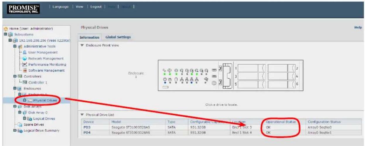
To see information about physical drives using the CLU menu:
- Go to the Main Menu >> Physical Drive Management
- Highlight the physical drive you want and press Enter. Basic information displays including the status of the physical drives.
View individual physical drive information (Vess A2200)
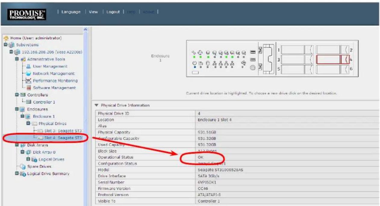

Note
In order that hard disk problems can be anticipated and dealt with smoothly, it is highly recommended to make sure that Media Patrol is enabled and running and Auto Rebuild is enabled if you are not using a spare drive. If using a spare drive, make sure it is healthy and available.
ANTICIPATING HARD DRIVE PROBLEMS
It is recommended that you always keep a healthy spare drive installed, and run Media Patrol as a background activity so a failing hard drive can migrate data to the spare before the status turns critical.
In Web PAM PROe, Media Patrol is enabled or disabled using the Background Activities menu, you can also create a schedule to run Media Patrol.
Enable PDM and Media Patrol
![PROMISE® TECHNOLOGY, INC. Language View Logout Help About Home (User: administrator) Subsystems 192.168.208.206 (Vess A2200s) Administrative Tools User Management Network Management Performance Monitoring Software Management Controllers Controller 1 Enclosures Enclosure 1 Physical Drives Slot 3: Seagate ST3: Slot 4: Seagate ST3: Disk Arrays Disk Array 0 Logical Drives Logical Drive 0 Spare Drives Logical Drive Summary Background Activities Information Settings Event Background Activities Scheduler Lock Background Activity Settings Rebuild Rate High Background Synchronization Rate Low Logical Drive Initialization Rate Medium Redundancy Check Rate Medium Migration Rate High PDM Rate High Transition Rate Medium Reassigned Block Threshold [1-512] 32 Blocks Error Block Threshold [1-2048] 32 Blocks Enable Media Patrol ✓ Enable Auto Rebuild ✓ Reset Submit Cancel](/content/2026/05/922956/images/2459840d023bd8bfc3c80f1da40a2c477e97d52fac47322dbd96f9fed33683d9.jpg)
- To enable Media Patrol, click on Background Activities in the Quick Links menu in the Home page, or, click on the Subsystem in Tree View then click on the Background Activities menu tab. Click to check the Enable Media Patrol option. Notice also that the Auto Rebuild option is here as well. If you want to automatically begin rebuilding a logical drive as soon as a faulty drive is replaced, make sure this option is enabled.
Start Media Patrol and Start PDM
![PROMISE® TECHNOLOGY, INC. Language View Logout Help About | Home (User: administrator) Subsystems 192.168.208.205 (Vess A2200s) Administrative Tools User Management Network Management Performance Monitoring Software Management Controllers Controller 1 Enclosures Enclosure 1 Physical Drives Slot 3: Seagate ST3: Slot 4: Seagate ST3: Disk Arrays Disk Array 0 Logical Drives Logical Drive 0 Spare Drives Logical Drive Summary Background Activities Information Settings Event Background Activities Scheduler Lock Background Activity Settings Rabuild Rate Background Synchronization Rate Logical Drive Initialization Rate Redundancy Check Rate Migration Rate PDM Rate Transition Rate Reassigned Block Threshold [1-512] Error Block Threshold [1-2048] Enable Media Patrol Enable Auto Rebuild Settings Start Media Patrol Start Rebuild Start PDM Start Transition Start Initialization 32 Blocks Start Redundancy Check 32 Blocks Reset Submit Cancel](/content/2026/05/922956/images/f72a799acd861e0deb5e4b59f9d46438cc38f49b11be77f319f3b435244f652f.jpg)
- To begin running Media Patrol manually, click on the menu expander to the right of the Background Activities tab and scroll down and select Start Media Patrol to see the Start Media Patrol menu. Then click on the Start button. - To schedule Media Patrol, click on the menu expander to the right of the Scheduler tab and scroll down and select Add Media Patrol Schedule to open the schedule menu. Use this menu to add a Media Patrol schedule.
To run Media Patrol using the CLU menu, go to Main Menu >> Subsystem Management >> Media Patrol and choose Start, Stop, Pause, or Resume. If you choose Stop, press Y to confirm.
REBUILDING A DISK ARRAY
When you rebuild a disk array, you are actually rebuilding the data on one physical drive.
- When a physical drive in a disk array fails and a spare drive of adequate capacity is available, the disk array begins to rebuild automatically using the spare drive.
- If there is no spare drive of adequate capacity, but the Auto Rebuild function is ENABLED, the disk array begins to rebuild automatically as soon as you remove the failed physical drive and install an unconfigured physical drive in the same slot. See "Making Rebuild Settings"
- If there is no spare drive of adequate capacity and the Auto Rebuild function is DISABLED, you must replace the failed drive with an unconfigured physical drive, then perform a Manual Rebuild.
How to Rebuild a Disk Array
When a physical drive is indicated to be degraded or in critical state, the array that contains that drive needs to be rebuilt. If you are not using Auto Rebuild (requires a Spare Drive), then you must rebuild the array manually after the affected drive has been replaced. Follow the instructions here to rebuild an array.
You will know that a logical drive is critical by looking at the Operational Status in the Logical Drive Information display.

To begin rebuilding the drive, go to the Local Host menu, the Background Activities and move the cursor to select Start Rebuild. A new menu appears.
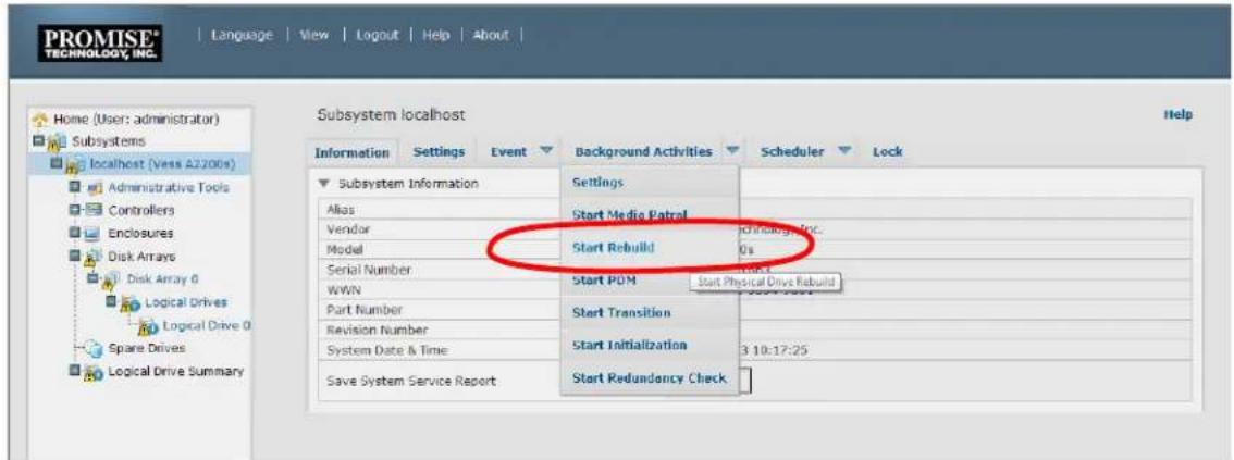
Now determine the source and target for the rebuild. In the new menu, choose the Source Physical Drive and Target Physical Drive from the menus, and click on the Submit button.

The progress of the rebuild is displayed in the Background Activities information display.

How to Save a Service Report
A Service Report is a detailed report covering the configuration and status of all components in your RAID system. A support technician or field engineer might request a service report for the purpose of diagnosis and troubleshooting.

To save a system configuration file:
-
Click on the Subsystem icon (IP address and device name) in Tree View to open the Subsystem Information display.
-
Click the Save button in the Save System Service Report row of the information display.
Information for the report is gathered and compiled. This action takes up to a few minutes, depending on the size of your RAID system.
- Determine where you want to store the file on the Host PC, then click the Save button in the pop-up menu.
The report saves to your Host PC as a compressed HTML file.
- Double-click the downloaded file to decompress it.
- Double-click the report to open it in your default browser.
Once you have the service report file, you can email it to a Technical Support representative.
The Service Report includes the following topics:
- About – Report utility
• BBM Info – Bad Block Manager - BGA Summary – Status and settings
- Buzzer Info
- Controller Info
- Disk Array Info
- Disk Array Dump info
- Disk Array Verbose Info
- Enclosure Info
- Error Table Info
• Event Info - NVRAM
• Event Info - Runtime
- LogDrive Info – Basic logical drive information
- LogDrive Dump Info – Diagnostic information
- Logical Drive Verbose Info – Full logical drive information
• Network Info – Virtual port
- Phydriv Info – Basic physical drive information
• Phydriv Verbose Info – Full physical drive
- SWMGT Info – Software management
• Service Setting – Email
• Service Setting – Webserver
- Spare Info – Basic spare drive information
- Spare Dump Info – Diagnostic information
- Spare Verbose Info – Full spare Drive information
- Statistic Info
- Subsystem info
- User Info
THE ALARM BUZZER IS SOUNDING, WHAT DOES THIS MEAN?
When you first power-up the Vess system beeps twice to show normal operation.
The audible alarm sounds at other times to inform you that the system needs attention. But the buzzer alarm is not specific. Check the device LEDs and Events displays or logs for more information.
When the alarm sounds:
- Check the front and back of the enclosure for red or orange LEDs.
- If email notification is enabled, check for new messages.
- Check the event log.
When a continuous tone sounds, there are multiple alarm patterns sounding at the same time (see example number 1 illustrated below).

bar
| Category | Value (s) | |---|---| | 1 | 25 | | 2 | 25 | | 3 | 25 | | 4 | 25 | | 5 | ∞∞ s |Other alarm patterns include three short buzzes followed by a longer silence, then repeated (example number 2 above). This can indicate a serious problem that requires immediate action such as high enclosure temperature or the system fan is not installed. If you hear this, check the System Status and Fan LEDs. If these are normal, it might indicate a physical drive problem, or a power supply problem. Check the event log for more information.
Pattern number 3 above might indicate an LD offline. Pattern number 4 might be an LD critical or bad sector on a physical disk.
HOW TO DISABLE THE ALARM BUZZER
To disable the buzzer with Web PAM PROe, open WebPAM PROe, click on the enclosure in Tree View, then click on the Buzzer menu expander, scroll to Settings and click the Enable Buzzer option box to remove the check mark. Click the Submit button.

To disable the buzzer in the CLU,
- From the Main Menu use the arrow keys to go to Buzzer, a list of Controllers appears with the current buzzer setting and status.
- Highlight Enabled and press the spacebar to toggle No.
- Press Control-A to save your settings.
In the unlikely event that your Vess A Class system will not boot normally, you might need to reinstall the operating system. This can be done by first creating a boot image on a USB flash memory device, then loading the Windows from that image. Note that the BIOS of the Vess Class A Series is configured to first look for the boot image in a USB drive. The install image is available at the PROMISE website online.

Note
In order to get the image file from PROMISE, you will need to have a PromiseLink account. If you do not have an account set up, follow the instructions below to get to the PromiseLink login page, then click on the Sign Up Now link in the login menu.
To download Windows Image Writer software and boot image, go to the Global English site for PROMISE and click on PromiseLink in the top link banner. In the PromiseLink home page, log in and follow the download instructions to get the Vess Class A Series boot image for the OS you are using.
Find PromiseLink

Make sure Global English is selected here
PromiseLink login page
REINTSALL WINDOWS
Follow the instructions below to reinstall the Windows OS. You will need another computer running Windows to perform this procedure.
-
Download ImageWriter (see instructions on previous page).
-
Download latest Vess Class A Series Windows image.
-
Insert the USB flash drive into your computer.
-
Use the Select USB drive menu to choose the drive letter of the USB flash memory device, then use the Select Image button to locate the image file you downloaded. When you have the USB drive letter and image file location selected, click Write! to begin. The process takes a few minutes. A boot image is written to the USB device.

-
Insert the USB drive into the Windows Vess Class A Series and boot up.
-
During the boot, a dialog menu asks if you want to reinstall Windows. Choose the option "i" to reinstall the Windows OS, you're existing RAID arrays will not be affected.
-
After the install is finished, remove the USB flash drive, boot the Vess A Class Series, then complete Windows setup.
REINSTALL LINUX
Follow the instructions below to reinstall the Linux OS. Notice that Windows Image Writer is also used for the creation of the boot image. So you will need another computer running Windows to perform this procedure.
- Download ImageWriter (see instructions on previous page).
- Download latest Vess Class A Series Windows image.
- Insert the USB flash drive into your computer.
-
Use the Select USB drive menu to choose the drive letter of the USB flash memory device, then use the Select Image button to locate the image file you downloaded. When you have the USB drive letter and image file location selected, click Write! to begin. The process takes a few minutes. A boot image is written to the USB device.
-
Insert the USB drive into the Linux Vess Class A Series and boot up.
-
You are prompted to select a destination for the Linux OS installation. Select "Internal flash" since this is the default location it will be selected automatically if you take no action.
-
You are prompted again to proceed or cancel. Enter "u" for Update, and the installation process launches.
LED TROUBLESHOOTING QUICK GUIDE
(See illustrations on next page)
 |  |  |  | Diagnosis Corrective Action | |
 | [X7HH] |  | [0H82] | 1. Voltage out of range2. Controller temperature above critical threshold | 3. Check power supply Status LED on back of device. Replace PSU if LED is red.4. Check enclosure air flow, remove any obstruction. |
 |  | [2TX2] |  | Hard drive temperature warning | Check enclosure air flow, check system fan, replace if necessary. |
 |  | [DSY3] | [2X0A] | Fan module is not cooling HDD to below critical threshold. | Replace system fan module. Allow time to reduce HDD temperature to below critical threshold. |
 |  |  | [X03D] | System fan failure Replace system fan module. | |
| [WWW4] |  |  | [ABYC] | CPU fan failure Replace CPU fan. | |
 | [D82D] | [CST6] |  | One or more LD offline Contact Technical Support | |
 | [848D] |  |  | One or more LD is critical Replace failed HDD and rebuild LD. | |
 | [K2X6] | [HS4T] | [XX62] | LD rebuilding | Wait until the rebuild is finished.When the rebuild is completed, both indicators will light green. |
| NOTE: Each power supply unit (PSU) located on the backplate has a Status LED indicator. If you see a Red LED indicator on a PSU, replace the unit.* The Vess A2600 Fan Status LED is located on the back of the device. See the Quick Start Guide or Product Manual for more information. | |||||

Red
Green

range (Amber)


Blinking Red

LED condition irrelevant

LED dark
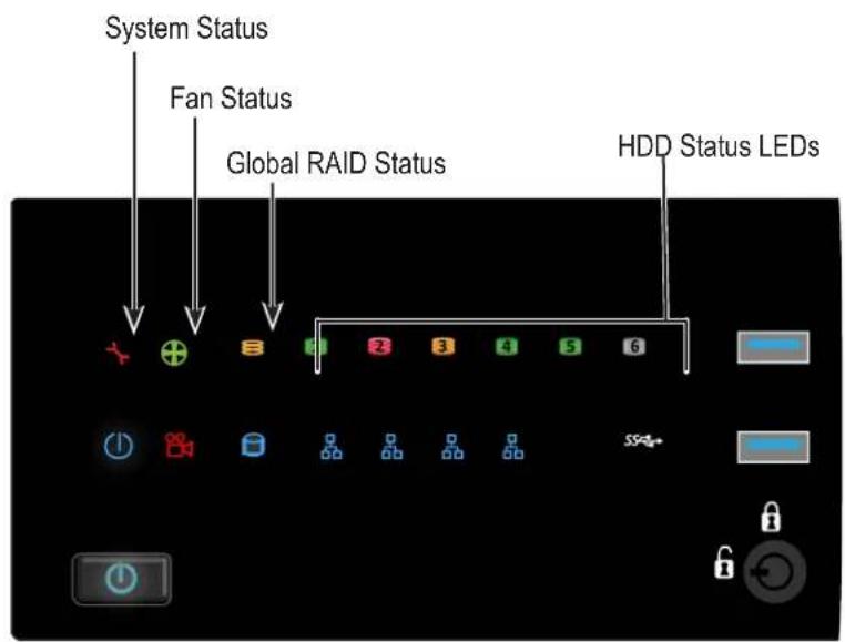
Vess A2200 front LED
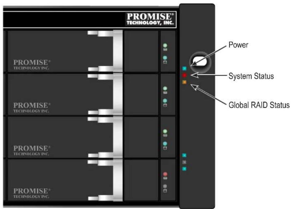
Vess A2600 LED right side

Vess A2600 drive carrier front LED
FAQ
Q: What is Vess A2200/2600 NVR storage appliances?
A: The Vess A2200/2600 NVR storage platform is PROMISE's NVR storage appliance solutions that are engineered specifically to be the best solution for midsize to large IP video surveillance deployments.
Q: How does it work for surveillance video recording?
A: The Vess A2200/2600 comes complete with your choice of Windows or Linux OS, a leading Video Management Software suite, or Disk Drives, minimizing the integration and installation process. Users no longer need an extra PC/server, add-on cards, or a separate connected storage for a complete video surveillance system; the Vess NVR storage appliance does it all!
Q: What should I do if the device OS fails?
A: Unlike regular COTS servers that come with standard Windows OS, the Vess A2200/2600 provides an embedded version that requires a certain process to rebuild the OS image. Users need to consult PROMISE tech support and follow installation guide to complete the setup.
Q: When I rebuild the Window embedded OS image, a product key# is required?
A: No, users do not have to enter any product key during re-installation. You need to get all the required software package like OS image(license built-in), RAID and device drivers from PROMISE Surveillance Storage web page for installation.
Q: Can I use more than one VMS with the Vess A2200/2600?
A: Yes, you can choose any other video management software with the Vess A2200/2600 as long as it functions compatible under WIN7 OS(64-bit).
Q: What's the standard warranty of Vess A2200/2600?
A: We provide the same standard three (3) years hardware warranty from the time of the delivery of the product to the original end user.
Q: Can I purchase extended warranty package to Vess A2200/2600?
A: Yes, we provide 2-year extended warranty program that uses the same order and support practice as Vess product series.
CONTACTING TECHNICAL SUPPORT
PROMISE Technical Support provides several support options for PROMISE users to access information and updates. We encourage you to use one of our electronic services, which provide product information updates for the most efficient service and support.
PROMISE E-Support: https://support.promise.com
PROMISE web site: http://www.promise.com//
When you contact us, please have the following information available:
• Product model and serial number
• BIOS, firmware, and driver version numbers
• A description of the problem / situation
- System configuration information, including: motherboard and CPU type, hard drive models, SAS/SATA/ATA/ATAPI drives & devices, and other controllers.
United States
580 Cottonwood Drive
Milpitas, Ca 95035, USA
Technical Support (E-Support): https://support.promise.com
Web site: http://www.promise.com//
Australia
Technical Support (E-Support): https://support.promise.com
Web site: http://www.promise.com//
EMEA
Netherlands
Science Park Eindhoven 5228
5692 EG Son, The Netherlands
Technical Support (E-Support): https://support.promise.com
Web site: http://www.promise.com//
Austria
Technical Support (E-Support): https://support.promise.com
Web site: http://www.promise.com//
France
Technical Support (E-Support): https://support.promise.com
Web site: http://www.promise.com//
Germany
Europaplatz 9
44269 Dortmund, Germany
Technical Support (E-Support): https://support.promise.com
Web site: http://www.promise.com//
Sweden
Technical Support (E-Support): https://support.promise.com
Web site: http://www.promise.com//
Switzerland ITF
Technical Support (E-Support): https://support.promise.com
Web site: http://www.promise.com//
Norway ITF
Technical Support (E-Support): https://support.promise.com
Web site: http://www.promise.com//
Belguim
Technical Support (E-Support): https://support.promise.com
Web site: http://www.promise.com//
Luxembourg
Technical Support (E-Support): https://support.promise.com
Web site: http://www.promise.com//
United Kingdom
Technical Support (E-Support): https://support.promise.com
Web site: http://www.promise.com//
Taiwan
Technical Support (E-Support): https://support.promise.com
Web site: http://www.promise.com//
China
Room 1108, West Wing, Shi Chuang Plaza, 22 Information Road
Shangdi IT Park, Haidian District, Beijing 100085
Fax: 86-10-8857-8015
Technical Support (E-Support): https://support.promise.com
Web site: http://www.promise.com//
Korea
Technical Support (E-Support): https://support.promise.com
Web site: http://www.promise.com//
Hong Kong
Technical Support (E-Support): https://support.promise.com
Web site: http://www.promise.com//
Singapore
Technical Support (E-Support): https://support.promise.com
Web site: http://www.promise.com//
Japan
3F, Mura Matsu Bldg, 3-8-5, Hongo Bunkyo-ku
Tokyo 113-0033, Japan
Technical Support (E-Support): https://support.promise.com
Web site: http://www.promise.com//
Limited Warranty
PROMISE Technology, Inc. ("PROMISE") warrants that this product, from the time of the delivery of the product to the original end user:
a) all components, except the cache backup battery, for a period of three (3) years;
b) the cache backup battery, for a period of one (1) year;
c) will conform to PROMISE's specifications;
d) will be free from defects in material and workmanship under normal use and service.
This warranty:
a) applies only to products which are new and in cartons on the date of purchase;
b) is not transferable;
c) is valid only when accompanied by a copy of the original purchase invoice.
d) Is not valid on spare parts.
This warranty shall not apply to defects resulting from:
a) improper or inadequate maintenance, or unauthorized modification(s), performed by the end user;
b) operation outside the environmental specifications for the product;
c) accident, misuse, negligence, misapplication, abuse, natural or personal disaster, or maintenance by anyone other than a PROMISE or a PROMISE-authorized service center.
Disclaimer of other warranties
This warranty covers only parts and labor, and excludes coverage on software items as expressly set above.
Except as expressly set forth above, PROMISE disclaims any warranties, expressed or implied, by statute or otherwise, regarding the product, including, without limitation, any warranties for fitness for any purpose, quality, merchantability, non-infringement, or otherwise. PROMISE makes no warranty or representation concerning the suitability of any product for use with any other item. You assume full responsibility for selecting products and for ensuring that the products selected are compatible and appropriate for use with other goods with which they will be used.
PROMISE does not warrant that any product is free from errors or that it will interface without problems with your computer system. It is your responsibility to back up or otherwise save important data before installing any product and continue to back up your important data regularly.
No other document, statement or representation may be relied on to vary the terms of this limited warranty.
PROMISE's sole responsibility with respect to any product is to do one of the following:
a) replace the product with a conforming unit of the same or superior product;
b) repair the product.
PROMISE shall not be liable for the cost of procuring substitute goods, services, lost profits, unrealized savings, equipment damage, costs of recovering, reprogramming, or reproducing of programs or data stored in or used with the products, or for any other general, special, consequential, indirect, incidental, or punitive damages, whether in contract, tort, or otherwise, notwithstanding the failure of the essential purpose of the foregoing remedy and regardless of whether PROMISE has been advised of the possibility of such damages. PROMISE is not an insurer. If you desire insurance against such damage, you must obtain insurance from another party.
Some states do not allow the exclusion or limitation of incidental or consequential damages for consumer products, so the above limitation may not apply to you.
This warranty gives specific legal rights, and you may also have other rights that vary from state to state. This limited warranty is governed by the State of California.
Your Responsibilities
You are responsible for determining whether the product is appropriate for your use and will interface with your equipment without malfunction or damage. You are also responsible for backing up your data before installing any product and for regularly backing up your data after installing the product. PROMISE is not liable for any damage to equipment or data loss resulting from the use of any product.
Returning the Product For Repair
If you suspect a product is not working properly, or if you have any questions about your product, contact our Technical Support staff, and be ready to provide the following information:
• Product model and serial number (required)
- Return shipping address
• Daytime phone number
• Description of the problem
• Copy of the original purchase invoice
The technician helps you determine whether the product requires repair. If the product needs repair, the technician issues an RMA (Return Merchandise Authorization) number.

Important
Obtain an RMA number from Technical Support before you return the product and write the RMA number on the label. The RMA number is essential for tracking your product and providing the proper service.
Return ONLY the specific product covered by the warranty. Do not ship cables, manuals, CDs, etc.
USA and PROMISE Technology, Inc.
Canada: Customer Service Dept.
Attn.: RMA # ____
47654 Kato Road
Fremont, CA 94538
Other Return the product to your dealer or retailer.
Countries: Contact them for instructions before shipping the product.
You must follow the packaging guidelines for returning products:
- Use the original shipping carton and packaging
- Include a summary of the product's problem(s)
- Write an attention line on the box with the RMA number
- Include a copy of your proof of purchase
You are responsible for the cost of insurance and shipment of the product to PROMISE. Note that damage incurred due to improper transport or packaging is not covered under the Limited Warranty.
When repairing returned product(s), PROMISE may replace defective parts with new or reconditioned parts, or replace the entire unit with a new or reconditioned unit. In the event of a replacement, the replacement unit is under warranty for the remainder of the original warranty term from purchase date, or 30 days, whichever is longer.
PROMISE pays for standard return shipping charges only. You must pay for any additional shipping options, such as express shipping.
APPENDIX: DRIVER INSTALLATION AND UPDATE
This appendix provides instructions for installing or updating the driver for the PROMISE RAID engine, as well as WebPAMPROe, the management GUI for the PROMISE Vess A2000 Series.
Follow these step-by-step instructions to install the latest hardware driver for the RAID and the latest WebPAMPROe version. These are available for download from the PROMISE website www.promise.com in a single compressed file package.
Instructions for uninstalling the driver and how to check the driver version are included after the update instructions.
Note, if you are using this procedure to update the driver and software, I/O operations will cease during the update procedure, so make sure any clients that are using the Live DB or video archive are alerted and prepared prior to starting the update.
Update/Installation Requirements
USB Flash Drive
A USB flash drive containing the update package is needed. Follow the instructions below to download the compressed file package and place a copy of the uncompressed file on the USB flash drive.
Operation Systems
The instructions in this document apply to Vess A2000 units running the following operating systems:
- Windows 7
- Windows Server 2008
- Windows 2012/2012 R2
Download Driver Package
- Go to the PROMISE website and click on Support near the top of the page, select the Download Center option. Use the two pull-down menus to first choose the Vess A2000 Series then either the Vess A2200 or Vess A2600 option (the driver is the same for both models). Under the heading Download search results below:
Click on the Drivers link and download Vess A2000_RAID Driver.
- Uncompress the file and place it on the USB flash drive used for the update.
UPDATE/INSTALL THE DRIVER
Follow these steps to complete the installation or update of the driver. If you have not yet downloaded the compressed files needed for updating the driver, see the previous page for download instructions.
For simplicity, variations of the terms "update" and "install" are used interchangeably in the following description to mean driver update or driver installation. The procedure for both updating or installing the driver are identical.
- Launch the Driver Update Package install application.
To launch, double-click on this icon:

- The first dialog menu to appear is a standard warning. Press the Run button to proceed.
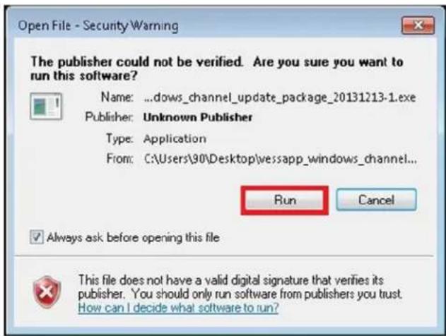
- A new dialog asks if you want to install the package. Click on Yes.

- It is necessary to reboot the Vess A2000 during the update process.
Click Yes to proceed with the update.

- In the Setup Wizard menu, click on the Next button to proceed.

At this point you might see a new menu depending on the status of the BIOS. See next page.
An automatic BIOS check is conducted. If the BIOS is up to date, the driver installation resumes in the setup menu.
If the BIOS is out of date, this menu appears.
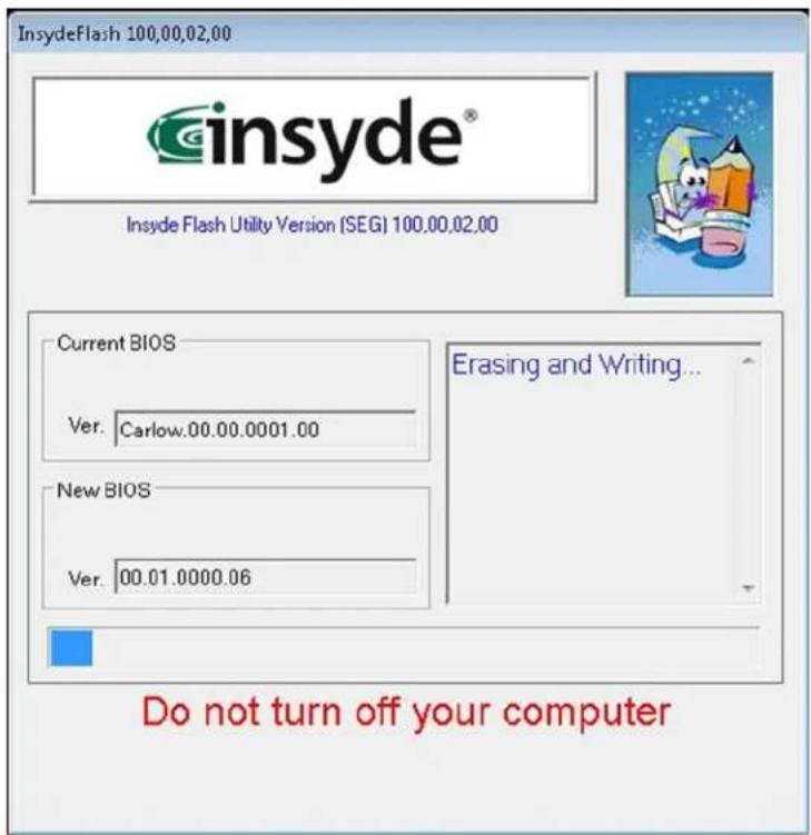
The BIOS is automatically updated and the driver installation/update resumes when the BIOS update is finished.
DO NOT turn off the computer during the BIOS update.
- The driver update resumes, press the Install button to proceed.

- In the Driver Installation Wizard menu, press the Next button

- Another Windows Security message appears.
Choose the option Install this driver software anyway.

- The last Windows Security menu asks if you want to install the driver.
Press the Install button to continue.
Note that you can tick the menu box Always trust software from Promise Technology, Inc. to avoid the Windows Security warnings for PROMISE software updates in the future.

- The Driver Installation Wizard menu informs you that the driver is now installed. Press the Finish button to continue.
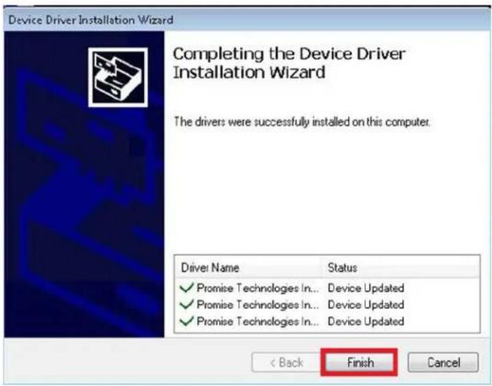
- The final Setup menu appears. Click on Finish.
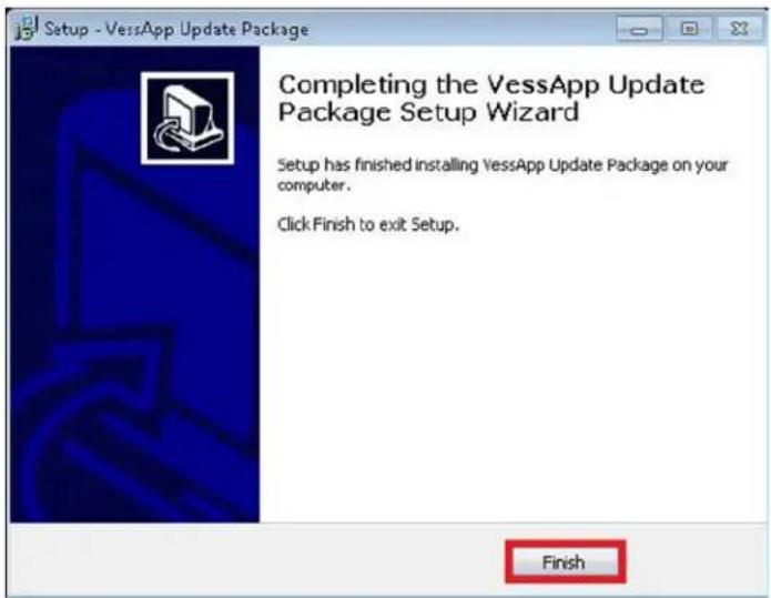
- A restart is required for the new driver to begin operating. Press the OK button to restart the
system.

UNINSTALL DRIVER
If you need to uninstall the driver for the RAID engine or undo installation of the Update Package, follow these steps.
- Open Programs and Features to uninstall the driver.
Go to Control Panel>All Control Panel Items>Programs and Features, choose the Uninstall option. Get the most recent version of the VessApp Update Package listed in the menu.

- A system restart is necessary are uninstalling the driver. Click Yes to continue.

- Confirm that you want to uninstall the driver by clicking on the Yes button.

- Click the OK button to continue.

- Click the OK button to restart Windows. Upon restarting the driver and software have been removed.
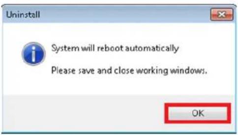
How to check DRIVER VERSION
To check if the Vess A2000 driver that is currently installed is up to date, you can check the RAID driver version or WebPAMPROebuild version with the CLI or WebPAMProE interfaces, or with the Windows device manager.
Check versions with CLI
To check the BIOS version, Firmware version, software version and Install package version with the CLI user interface:
- To open the CLI menu, click on the Windows Start button, type clitest in the text entry menu and press Enter. This displays the icon for the shortcut to the CLI interface. Double-click on the icon.

- The RAID driver Version is listed at the top of the Login menu.

- To view additional version information, login and type ctrl -v.
Note that the default User Name is administrator and the Password is password.
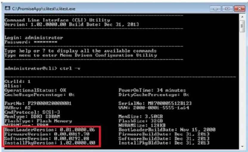
The version information is listed below the administrator prompt. See example above.
Check versions with WebPAM PROe
To check the Install package version with the WebPAMPROe user interface:
- To open WebPAMPROe, click the shortcut of CLI of WebPAMProE on the desktop.

- Login. The default User Name is administrator and the Password is password.

- To view the Driver Version, go to Controller >Controller1>Install PKg Version, the package version is listed in the menu display (see below).
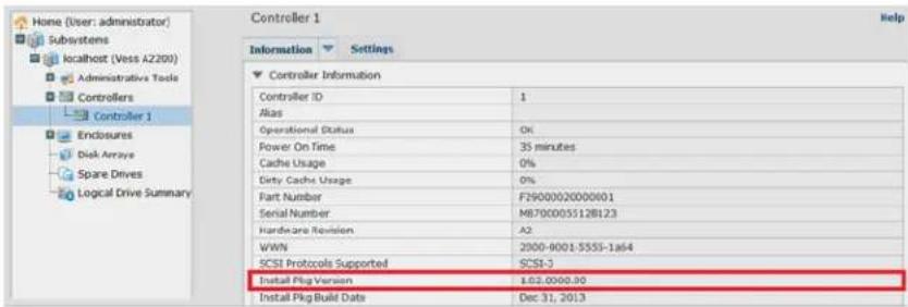
Check versions in windows device manager
To get the RAID driver version using the Windows Device Manager:
- Open the Windows Device Manager. Go to Start > Control Panel > Device Manager.
Double-click the Device Manager icon

Device Manager
- Look for Storage controllers and right-click on the Properties option in the pop-up menu.
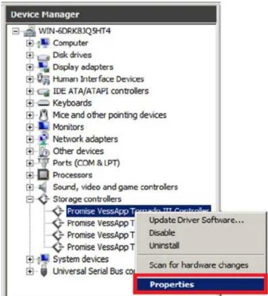
- Click the Driver tab to see the driver version.

APPENDIX: WINDOWS SYSTEM RECOVERY
This appendix provides step-by-step instructions creating a recovery disk used for restoring the Windows operating system and programs in the event of a Windows OS failure. The storage device used for the recovery disk can be a DVD drive (read-write), network storage or internal RAID on the Vess A2000. This recovery disk is then used to restore the system drive to a state identical to what it had been when it was last backed up.
Following the recovery disk creation instructions, and instructions for restoring the Windows operating system from the previously created recovery disk. Once the operating system has been restored, the data stored on the RAID volume of the Vess A2000 can again be accessed.

Important
A recovery disk must be created while the Windows OS is functioning. It is recommended that the system disk (the mSATA C drive) be backed up on a regular schedule. The Vess A2000 can be scheduled for regular system drive backups to the RAID volume. Then, using one of the system recovery methods (see below), the Windows OS and PROMISE RAID are reinstalled so that the previously saved system data, including device drivers and VMS software, can be retrieved from the RAID volume.
Different ways to backup the system disk
There are three options for backing up the system disk, backup to the RAID, to DVD or to a drive connected via SAN or NAS. Also, it is possible to setup the Vess A2000 to make scheduled backups to either the RAID or to a network drive.
The recovery procedure installs a minimal operating system and the PROMISE RAID engine. With these installed, the system disk can be restored to the same state as it existed when saved to the internal RAID volume, network drive or DVD.
To backup to the RAID volume, it is first necessary to create a Virtual Hard Disk. See “Virtual hard disk” on page 275 for details.
Before you start
Make sure that you have the items listed below before beginning with the recovery process. Contact Promise FAE Support for the recovery image file and image writer utility.
Hardware needed
- Monitor, mouse and keyboard. Please refer to the user manual for instructions on connecting hardware to the Vess A2000.
- Storage device (HDD, DVD, or network location) containing the system recovery data
- USB Flash memory device with at least 4GB available space
Software needed
- Windows native software backup and restore
• VessAppImageWriter.exe
• Recovery Environment (RE) Image
This is available from Promise website, FAE Support or Sales Engineers.
VIRTUAL HARD DISK
To backup the system disk to the RAID volume on the Vess A2000, it is necessary to create a special volume used only for this purpose call the Virtual Hard Drive (VHD). Follow the procedure here to first create the VHD, then you can backup the Windows disk to the VHD.

Important
Before creating the VHD, make sure the drive used for the VHD is labeled "Prom_data1"
Check available space
First check to make sure there is enough disk space for the recovery process.
- Click on the Computer desktop icon to check the drive Prom_data1 (D: ).
- Make sure the name of the RAID volume used for the VHD is Prom_data1, change the name if necessary.
- Check to see that Prom_data1 (D:) has a minimum of 150GB free space. If necessary, delete old data to free up enough space (150GB). For systems running Milestone surveillance software, operate milestone parameters configurations to overwrite or retention tie time for this purpose.

Create the virtual hard disk for system backup
After verifying there is enough space to accommodate the VHD, follow these steps to create it.
- Right-click on the Computer icon on the desktop and select the Manage option.

- The Computer Management menu appears.

- Right-click on Disk Management and choose the Create VHD option.
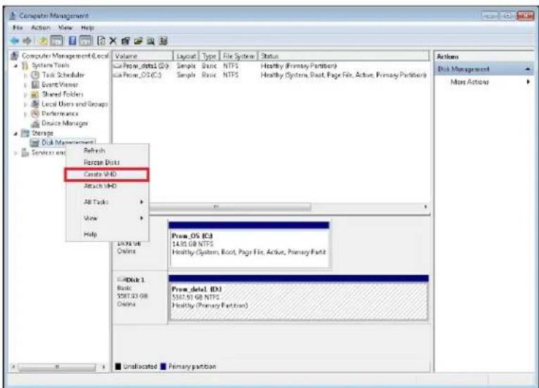
- In the new menu, leave the Fixed size option selected and click the Browse button.

- Choose the path Computer > Prom_data1(D:) and type backup in the File name field.


Important
The file name must be "backup".
- In the new menu, type 100 and select GB as the Virtual hard disk size. Click OK.

- The VHD creation process begins. The progress of the process displays in the status bar at the bottom of the menu.

- When the VHD is created, a new disk, Disk 2 appears. This disk is not yet initialized.

- Right-click on Disk 2 and choose Initialize Disk to begin the initialization procedure.

- Disk 2 and the option MBR are already selected. Click OK.

- When the initialization is finished, Disk 2 is Online.
![Computer Management File Action View Help Computer Management [Local] System Tools Task Scheduler Event Viewer Shared Folders Local Users and Groups Performance Device Manager Storage Disk Management Services and Applications Volume Layout Type File System Status □From_data1 (D:) Simple Basic NTPS Healthy (Primary Partition) □From_OS (C:) Simple Basic NTPS Healthy (System, Boot, Page File, Active, Primary Partition) Actions Disk Management More Actions □Disk 1 Basic 5587.03 GB Online Prox_data1 (D:) $5587.03 GB NTFS Healthy (Primary Partition) □Disk 2 Basic 560.00 GB Online 100.00 GB Unallocated ■ Unallocated ■ Primary partition](/content/2026/05/922956/images/580b1d6de828adbb7bc618f9ab457624d810da3d6e9972d737e416859c0413c6.jpg)
- Right-click on Disk 2 and choose New Simple Volume.
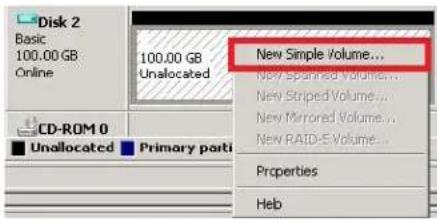
- Accept all the default values in the menus that follow. Click Next.
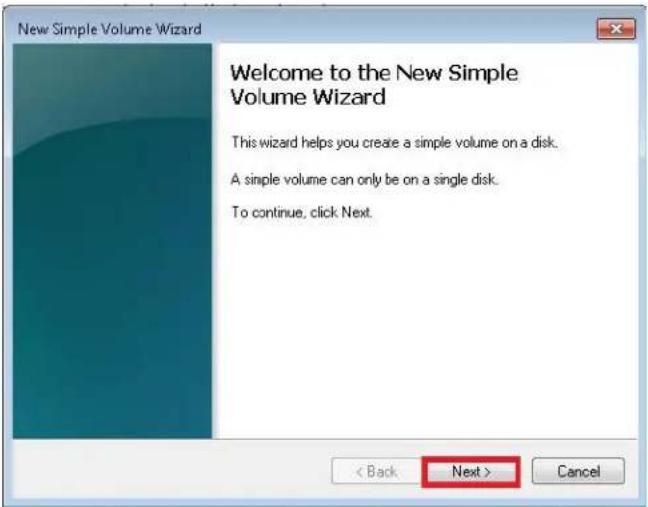
- Click Next.

- The drive letter is E. Click Next.
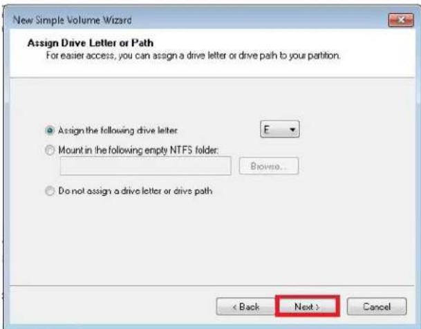
- Click Next.

- Click Finish.

- After the New Volume is created, close the Computer Management menu and reboot the system.


Important
The new VHD must be attached after system reboot. Follow the procedure below to Attach VHD.
Attach the VHD
- After restarting the Vess A2000, go to the Computer Management menu again. Right-click on Disk Management under Storage and choose Attach VHD.
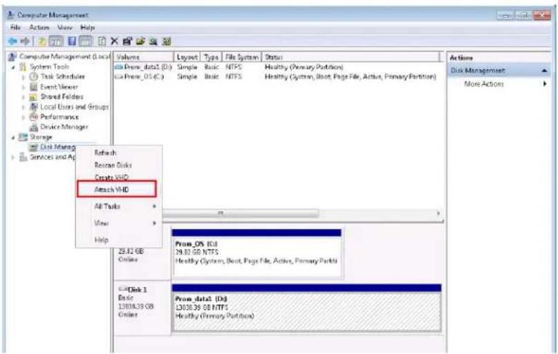
- In the new menu, Browse to locate backup.vhd on the Prom_data1(D):.


3. Click OK

- The new volume appears in the Computer Management menu. The VHD is now ready.
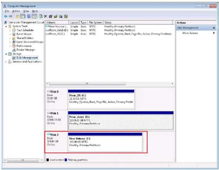
Simple Windows system backup
Two methods for system backup are described in this guide. The first is a simple Stand Operating Procedure system disk backup for Windows on the RAID volume, on a DVD, or on a remote drive connected via the network (NAT or SAN).
The other method described in a later section is for regular scheduled backups. Scheduled backups can be done on the RAID volume or on a remote drive via SAN or NAT.
Backup system on RAID disk-Windows 7
Follow these steps to perform a simple Windows system backup to the RAID volume.
- Click the Windows Start icon

- Click on Control Panel

- Click on System and Security
Adjust your computer's settings

System and Security
Review your computer's status
Back up your computer
Find and fix problems

Network and Internet
View network status and tasks
Choose homegroup and sharing options

Hardware and Sound
View devices and printers
Add a device

Programs
Uninstall a program
4. Click on Backup and Restore

Backup and Restore
Back up your computer | Restore files from backup
5. Click the Create a system image option to backup system once
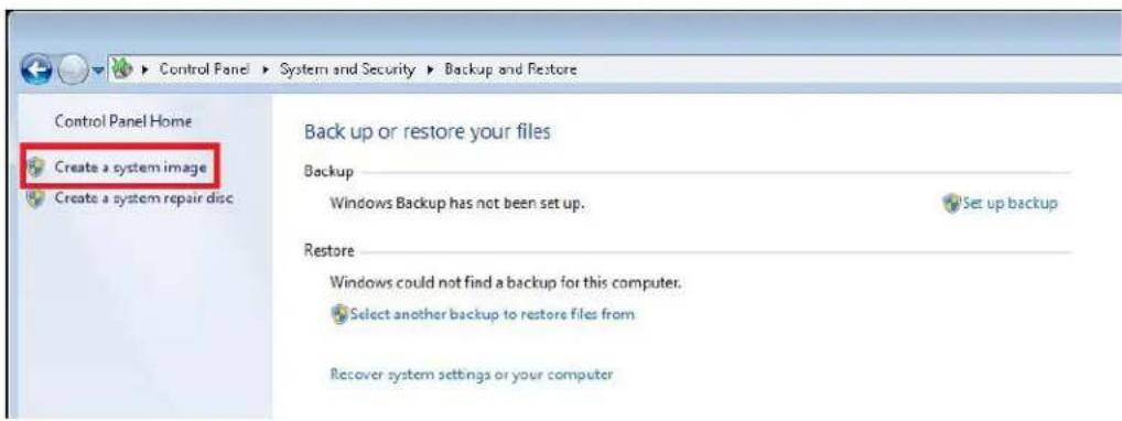

Note
If you want to backup system on schedule, see "Schedule system backup to RAID - Windows 7" on page 313.
- Tick the On a hard Disk option, choose the New Volume (E:) 99.91GB free and click Next. This New Volume (E:) is the VHD created previously.

- Select the drive Prom_OS(C:) (System) and click button Next. Make sure to select only the C Drive.

- Click on the Start Backup button.

The backup begins.

- When the backup program has finished, click the No button in the menu that appears.

- Click the Close button. The backup is finished.

Backup system on DVD - Window 7
Follow these instructions to perform a simple system backup to DVD.
- Click the Windows Start icon

- Click on Control Panel

- Click on System and Security
Adjust your computer's settings

System and Security
Review your computer's status
Back up your computer
Find and fix problems

Network and Internet
View network status and tasks
Choose homegroup and sharing options

Hardware and Sound
View devices and printers
Add a device

Programs
Uninstall a program
- Click on Backup and Restore

Backup and Restore
Back up your computer
Restore files from backup
- Click on the Create a system image option.
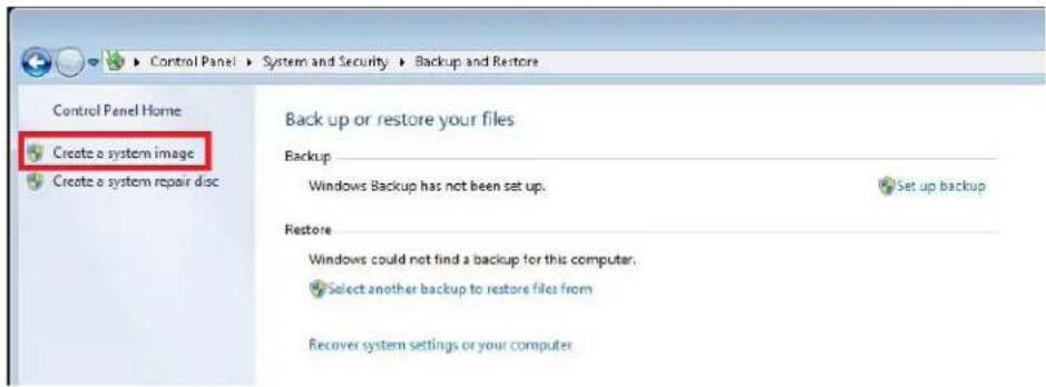
-
Connect an external DVD-RW device loaded with a blank DVD to a USB port on the Vess A2000.
-
Select On one or more DVDs and click the Next button.

- Click Next. The drive is already selected.

- Click the Start Backup button.

- When the system disk is backed up, a new menu appears. Click the OK button.

The backup begins. The progress is displayed in a new menu.

- A new menu appears when the data is written. Click the No Button
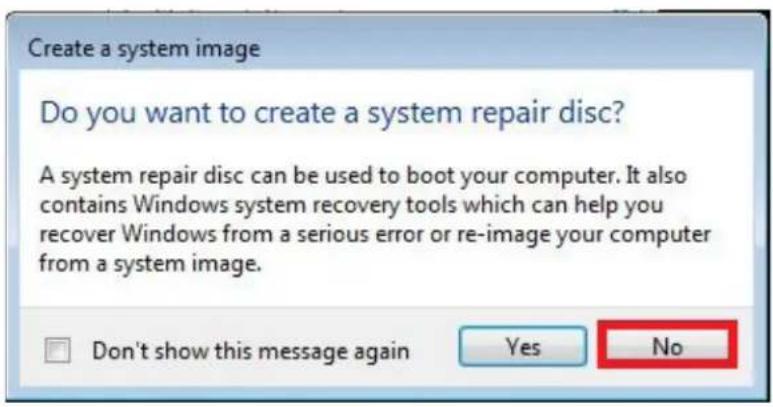
- Click the Close button

Backup on Network Location- Windows 7
Use the procedure described below to backup the Windows 7 system disk to a network volume on a SAN or NAS.
- Click the Windows Start icon.

- Click on Control Panel.

- Click on System and Security.
Adjust your computer's settings

System and Security
review your computer's status
Back up your computer
Find and fix problems

Network and Internet
View network status and tasks
Choose homegroup and sharing options

Hardware and Sound
View devices and printers
Add a device

Programs
Uninstell e program
- Click on Backup and Restore.

Backup and Restore
Back up your computer
Restore files from backup
- Click on the Create a system image option.


Note
If you want to backup system on schedule, see "Schedule system backup to network - Windows 7" on page 316.
- Select On a network location and enter the IP address of the network drive, click Next.
Note that Windows 7 Home series does not support backups to a network location.

- Enter the path for the Network Location and the Username and Password needed. Click OK.

- Click the Next button.

- Click the Start Backup button.
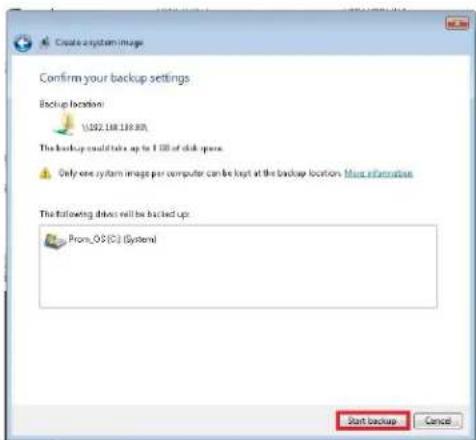
- Click the OK button.
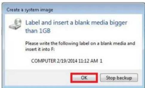
- Click the No button.
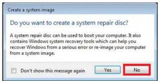
The backup process runs. The progress displays in a new menu.
- When the backup is completed, click the Close Button
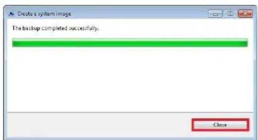
Backup system on RAID disk-Windows 2008/Windows 2012 Server
Follow these steps to backup the Windows system disk to the RAID volume on the Vess A2000.
- Open the Windows Server Backup program.
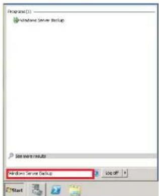
- Select the Backup Once action.


Note
If you want to backup system on schedule, see "Schedule system backup to RAID - Windows 2008 Server" on page 320.
- Select Different options and press the Next> button
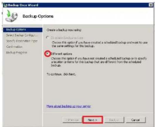
- Select Custom and click the Next> button.
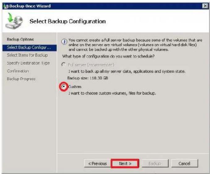
- Click the Add Items button.

- Check to enable "Bare metal recovery, System state and Prom_OS(C:), and click OK.
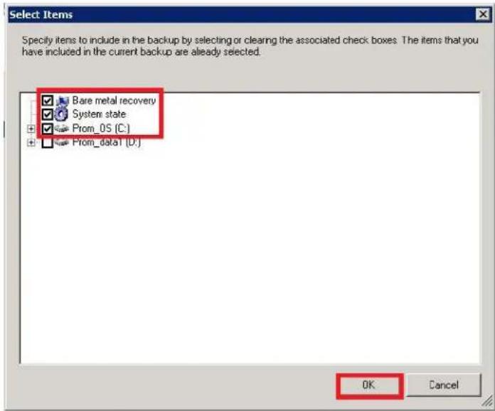
- Click the Next> button
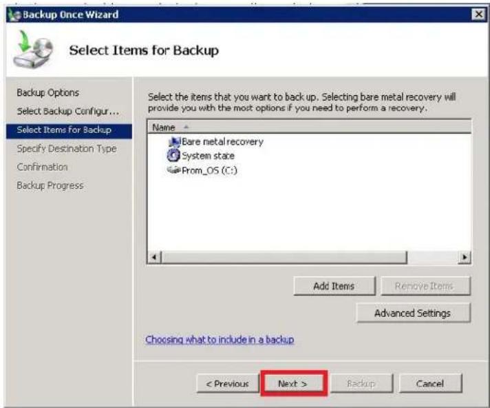
8. Select Local drives and click Next>.

9. Select the Backup destination: New Volume (E:) and click Next.
Note that the New Volume (E:) is the VHD created previously.

- Press the Backup button.

- Wait a few minutes for the backup process to be completed successfully. When the Status indicates it is Completed click the Close button.
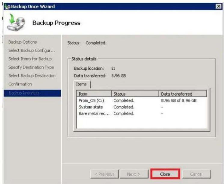
Backup system on DVD - Windows 2008 Server
Use this procedure to backup a Windows 2008 Server system on a DVD.
- Open the Windows Server Backup program.

- Select the Backup Once action.

- Select Different option and press the Next> button.

- Select Custom and press the Next> button.
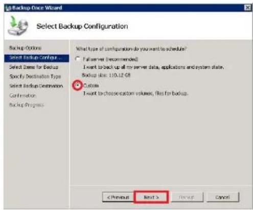
10. Click OK.
11. Wait a few minutes for the backup process to be completed. Click the Close button to close
this windows. Backup on Network Location - Windows 2008 Server
Follow these steps to backup the Windows 2008 system drive to a network volume on a NAS or SAN. 1. Open the Windows Server Backup program.  2. Select the Backup Once action.  Note
If you want to backup system on schedule, see "Schedule system backup to network - Windows 2008 Server" on page 325. 3. Select Different option and click Next>. 4. Select Custom and click Next>.
5. Click the Add Items button.
 6. Check to enable "Bare metal recovery, System state and Prom\_OS(C:), and click OK.  7. Click the Next> button.  8. Select Remote shared folder and click Next>.  9. Enter the path for the Network Location, don't change the Access control settings. Click Next.  10. Enter the User name and Password for login.  11. Click the Backup button.  12. Wait a few minutes until the Status indicates the backup is Completed, click the Close button. SCHEDULED WINDOWS BACKUP
Follow the instructions to schedule regular backups for Windows 7 or Server 2008 to the local RAID volume or to a network drive on a SAN or NAS.Schedule system backup to RAID - Windows 7
To setup a schedule for backing up the Windows 7 system disk to the RAID volume: 1. Go to Control Panel > Backup and Restore, select Set up backup.  2. Select New Volume(E:), this is the VHD volume created previously. Click the Next button  3. Select Let me choose and click the Next button.  4. Click to enable Back up data for newly created users, Computer's Libraries and Prom\_OS, click the Next button  5. Select Change schedule.  6. Set the backup schedule and click the OK button  7. Click the Save setting and run backup to start backup. The backup will run on schedule. Schedule system backup to network - Windows 7
To setup a schedule for regular system backups to a network volume: 1. Go to Control Panel > Backup and Restore. Select the Set up backup.  2. Click the Save on a network... button  3. Enter the network path for the drive or Browse to locate it, the Username and Password used for access. Click the OK button.  4. Select the network location for the backup destination and click the Next button  5. Select the Let me choose and click the Next button.  6. Select to enable Back up data for newly created users, Computer's Libraries, and Prom\_OS (C:), click the Next button  7. Click on Change schedule.  8. Set the schedule and click the OK button.  9. Click the Save setting and run backup button. The backup schedule is set. Schedule system backup to RAID - Windows 2008 Server
Follow these steps to create a schedule for backing up the Windows 2008 Server system disk to the local RAID volume. 1. Go to Control Panel > Backup and Restore. Select the Backup Schedule.  2. Click the Next button.  3. Select the Custom and click the Next> button.  4. Click the Add Items button.  5. Select to enable Bare metal recovery, System state and Prom\_OS(C:), click the OK button.  6. Click the Next> button.  7. Set the schedule and click the Next button.  8. Select Back up to a volume and click the Next> button.  9. Select to enable the VHD created previously click the OK button.  10. Click the Next> button.  11. Click the Yes button. 12. Click the Finish button.
13. Click the Close button.
Schedule system backup to network - Windows 2008 Server
Follow these steps to setup a schedule for backing up the system Windows 2008 Server disk to a network volume on a SAN or NAS.1. Select the Backup schedule.
2. Click the Next> button.
 3. Select the Custom and click the Next> button.  4. Click on Add Items.  5. Select to enable Bare metal recovery, System state and Prom\_OS(C:), click the OK button.  6. Click the Next> button.  7. Set the backup schedule and click the Next> button.  8. Select the Back up to a shared network folder and click the Next> button. 9. Click the OK button.
10. Enter the network path to the backup destination and click the Next> button. Leave the Access Control settings to the default values.
11. Enter the User name and Password to access the drive and click the OK button.
12. Click the Finish button
13. Click the Close button. The schedule is now setup.
SYSTEM RECOVERY
The system recovery process requires that a minimal operating system called the and RAID engine first be installed on the C drive. The files loaded to the C drive are called the Recovery Environment (RE). Once the RE is installed the remaining elements of the system disk can be restored from the local RAID volume, DVD or a network drive connected via SAN or NAS. Follow the instructions in “Create the recovery environment” on page 331, then proceed to recover the system disk according to the method by which it was backed up. See the following sections for the final recovery stage: - “Restore from RAID” on page 332 - "Restore from DVD" on page 336 - "Restore from network drive" on page 339Create the recovery environment
The procedure described here is used to load a Recovery Environment onto the system drive (mSATA C drive) of the Vess A2000. The procedure is the same for Windows 7 and Windows 2008 Server operating systems. 1. Download VessAppImage.exe and the Recovery Environment (RE) Image. The recovery image and image write utility are available for download from PROMISE. Please ask FAE Supporting Engineers, Sales, and Sales Engineering staff help downloading the files needed. 2. Launch VessAppImageWriter.exe.  3. Select the USB drive and Select Image, browse to locate the downloaded RE Image and click on Write.  4. When the process is completed the message Flash success appears. Click OK. Restore from RAID
Follow these steps to restore the system disk from a saved version on the local RAID volume. 1. Create the Recovery Environment if you have not yet done so. See "Create the recovery environment" on page 331. 2. Connect a keyboard, mouse and monitor and insert the USB flash drive containing the RE Image into and a USB port on the Vess A2000. 3. Power on the Vess A2000. The system will boot from the USB drive. 4. Click the Next> button in the first menu that appears.  5. Select Restore your computer using a system image that you created earlier and click the Next> button.  6. The Select a system image should be chosen already with the location and other information appearing in the menu. Click the Next> button.  7. Choose the location and click the Next> button.  8. Select the date and time and click the Next> button.  9. Click the Next> button.  10. Click the Finish button.  11. Click the Yes button.  12. Windows begins restoring the system disk to the state at which it was previously saved. When the re-image process is done, you will be prompted to restart. After rebooting the system image and recovery procedure is completed. Restore from DVD
Follow these steps to restore the system disk from a saved version on a DVD drive. 1. Create the Recovery Environment if you have not yet done so. See "Create the recovery environment" on page 331. 2. Connect the DVD drive with the saved system disk inserted, a keyboard, mouse and monitor and insert the USB flash drive containing the RE Image into and a USB port on the Vess A2000. 3. Power on the Vess A2000. The system will boot from the USB drive. 4. Click the Next> button in the first menu that appears.  5. Select Restore your computer using a system image that you created earlier and click the Next> button.  6. The Use the latest available system image should be chosen already with the location and other information appearing in the menu. Click the Next> button.  7. Click the Next> button.  Click the Finish button.  8. Click the Yes button.  9. Windows begins restoring the system disk to the state at which it was previously saved. When the re-image process is done, you will be prompted to restart. After rebooting the system image and recovery procedure is completed.Restore from network drive
Follow these steps to restore the system disk from a saved version on the local RAID volume. 1. Create the Recovery Environment if you have not yet done so. See "Create the recovery environment" on page 331. 2. Connect a keyboard, mouse and monitor and insert the USB flash drive containing the RE Image into and a USB port on the Vess A2000. 3. Power on the Vess A2000. The system will boot from the USB drive. 4. Click the Next> button in the first menu that appears.  5. Select Restore your computer using a system image that you created earlier and click the Next> button.  6. Choose the Select a system image option and click the Next> button.  7. Click the Advanced button.  8. Click on the Search for a system image on the network option.  9. Specify the location of the system image and click OK.  10. Enter the Username and Password to connect to network drive and click OK.  11. Select the Location and click Next>.  12. Select the date and time of system image to use for the system restore and click Next>.  13. Click Next. 14. Click Finish.
 15. Click Yes. Windows begins restoring the system disk to the state at which it was previously saved. When the re-image process is done, you will be prompted to restart. After rebooting the system image and recovery procedure is completed. APPENDIX: IO TERMINAL BOARD INFORMATION
This Appendix answers questions that PROMISE customers might have concerning the function of the I/O terminal board available as an option on the Vess A2000 NVR Storage Appliance models. Vess A2200 rear panel natural_image
Front view of a server rack with multiple drive units, ports, and a central display showing network ports (no readable text or symbols)natural_image
Front view of a computer power drive showing fan, ports, and internal hardware (no text or symbols visible)I/O Terminal Board Features
• Supports 8 input sensors, 8 output alarms and a RS-422/485 interface. - Sensor Input Connector: Connect sensor input lines. An external device issues a warning to the I/O terminal board controller. - Alarm Output Connector: Connect alarm output lines. Used to send pre-defined alarm signals.Pin Assignments
Sensor Input Connector
Pin Number SENSOR IN| 1 3.3 V |
| 2 IN_8 - |
| 3 IN_8 + |
| 4 IN_7 - |
| 5 IN_7 + |
| 6 IN_6 - |
| 7 IN_6 + |
| 8 IN_5 - |
| 9 IN_5 + |
| 10 IN_4 - |
| 11 IN_4 + |
| 12 IN_3 - |
| 13 IN_3 + |
| 14 IN_2 - |
| 15 IN_2 + |
| 16 IN_1 - |
| 17 IN_1 + |
| 18 GND |
Alarm Output Connector
Pin Number ALARM OUT| 1 GND |
| 2 OUT_8 - |
| 3 OUT_8 + |
| 4 OUT_7 - |
| 5 OUT_7 + |
| 6 OUT_6 - |
| 7 OUT_6 + |
| 8 OUT_5 - |
| 9 OUT_5 + |
| 10 OUT_4 - |
| 11 OUT_4 + |
| 12 OUT_3 - |
| 13 OUT_3 + |
| 14 OUT_2 - |
| 15 OUT_2 + |
| 16 OUT_1 - |
| 17 OUT_1 + |
| 18 GND |
| 19 RS-422/485 TX - |
| 20 RS-422/485 TX + |
| 21 RS-422 RX - |
| 22 RS-422 RX + |
How to use the I/O Receptacle
Insert a small flat-head screwdriver into the slot above the hole you want to connect. Hold the screwdriver in place and insert the wire, then release the screwdriver. See illustration below.   Operation Examples
Below are examples of how to connect and check the status for devices used with the I/O terminal board.Sensor Input Connection
The illustration below is used as an example. In this example a motion sensing camera is connected. - Connect the SENSOR\_IN + on the Vess I/O terminal interface with an external camera Alarm Out + (Red wire in illustration) - Connect the SENSOR\_IN - on the Vess I/O terminal interface with an external camera Alarm Out - (Black wire in illustration) See "Sensor Input Connector" on page 347 for pin assignments. Check Sensor Input Status in CLI
To check the status for the device that issues a warning to the terminal board. Follow these steps: 1. Open the CLI interface, typeAlarm Output Connection
The illustration below is used as an example. The example used is an alarm. - Connect the ALARM\_OUT + on the I/O terminal interface to the 3.3V or 5V connection on the external alarm device (Blue wire in illustration) - Connect the ALARM\_OUT - on the I/O terminal interface to the Input + connection on the external alarm device (Red wire in illustration) - Connect the ALARM\_GND - on the I/O terminal interface to the Input - connection on the external alarm device (Black wire in illustration) See "Alarm Output Connector" on page 348 for pin assignments. Enable sensor output in CLI
To enable the alarm connected to the sensor device, that is, to enable the ability of the terminal board send a signal to the alarm when the sensor device is triggered, follow these steps: 1. Open the CLI interface, typeDisable Alarm Device
To disable the alarm device: 1. Open CLI and typeConnecting an Analog Cameras with RS-232/422/485 ports
These are important points to keep in mind when using or connecting and using analog cameras. • Only one connector can be used at one time: RS-232C, RS-422, or RS-485 - For pan, tilt and zoom operations, connect a camera control cable to RS-232 connector or the RS-422/485 connector (four rightmost pins on the alarm output connector).   \- RS-232 Port 1: This is used for control line connection to an uninterruptible power supply (UPS). \- RS-232 Port 2 : Use this to connect to analog cameras via the analog camera input cable. Note: This connector cannot be used at the same time as the RS-422/485 connector. \- RS-422/RS-485 : Use this to connect to analog cameras via the analog camera input cable. Note: This connector cannot be used at the same time as the RS-232 connector.Configure connection in CLI
Configure RS-232 (Port 2)
Choosing this option enables the RS-232 port and disables the RS-422/485 port on the terminal board. 1. Open CLI and typeConfigure RS-422/485 (I/O Terminal Board)
Choosing this option enables the RS-422/485 port on the terminal board and disables the RS-232 port. 1. Open CLI and typeflowchart
graph TD
    A["Camera"] -->|Analog cameras (RS-485 control)| B["Server Rack"]
    C["Camera"] -->|Analog cameras (RS-422 control)| B
    D["Camera"] -->|Analog cameras (RS-232 control)| B
    B --> E["Internal Control Panel"]
    E --> F["IO/USB Interface"]
    style E fill:#f9f,stroke:#333,stroke-width:2px
Terminal Board FAQ
Q1: How can I know which device has an input signal (Sensor Status = Enable) to I/O terminal board controller from sensor status in CLI? A: Use this table to determine which camera is sending the warning (Sensor Status = Enable). Note that when the Sensor Status in the CLI is “0”, indicates signal input on all SENSOR IN; a Sensor Status of “1” indicates SENSOR IN 2, 3, 4, 5, 6, 7 and 8 have signal input; SENSOR IN 1 ( 2^0 ) has no signal input.Example #1
Sensor Status is "72" in CLI. \- 2^6 plus 2^3 equals 72 => SENSOR IN\_7 and SENSOR IN\_4 have no input signal (i.e. Sensor Status = Disable). • All other SENSOR IN (1, 2, 3, 5, 6, 8) have input signals. (i.e. Sensor Status = Enable).Example #2
Sensor status is "255" in CLI. \- All SENSOR IN (1, 2, 3, 4, 5, 6, 7, 8) have no input signals. (i.e. Sensor Status = Disable).| Pin No. | SENSOR IN | Sensor Status | |
| EnableDis | able | ||
| 2 IN_8 | 0 2 | 7 | |
| 3 IN_8 | + | ||
| 4 IN_7 | 0 2 | 6 | |
| 5 IN_7 | + | ||
| 6 IN_6 | 0 2 | 5 | |
| 7 IN_6 | + | ||
| 8 IN_5 | 0 2 | 4 | |
| 9 IN_5 | + | ||
| 10 IN_4 | - 0 2 | 3 | |
| 11 IN_4 | + | ||
| 12 IN_3 | - 0 2 | 2 | |
| 13 IN_3 | + | ||
| 14 IN_2 | - 0 2 | 1 | |
| 15 IN_2 | + | ||
| 16 IN_1 | - 0 2 | 0 | |
| 17 IN_1 | + | ||
Q2: How can I know which external alarm issues a warning (Alarm Status = Enable) from alarm status in CLI?
A: Use this table that you can calculate which external alarm is warning (Alarm Status = Enable). Note that when the Alarm Status in the CLI is "0", indicates warning on all ALARM\_OUT; an Alarm Status of "1" indicates ALARM\_OUT 2, 3, 4, 5, 6, 7 and 8 have signal input; ALARM\_OUT (2 ^0 ) has no warning.Example #1
Alarm Status is "129" in CLI. \- 2^7 plus 2^0 equals 129 => ALARM\_OUT.\_8 and ALARM\_OUT\_1 have no warningExample #2
Alarm status is "255" in CLI. • No warning (signal output) on all alarms.| Pin No. ALARM OUT | Alarm Status | ||
| EnableDisable | |||
| 2 OUT_8 - 0 2 | 7 | ||
| 3 OUT_8 + | |||
| 4 OUT_7 - 0 2 | 6 | ||
| 5 OUT_7 + | |||
| 6 OUT_6 - 0 2 | 5 | ||
| 7 OUT_6 + | |||
| 8 OUT_5 - 0 2 | 4 | ||
| 9 OUT_5 + | |||
| 10 OUT_4 - 0 2 | 3 | ||
| 11 OUT_4 + | |||
| 12 OUT_3 - 0 2 | 2 | ||
| 13 OUT_3 + | |||
| 14 OUT_2 - 0 2 | 1 | ||
| 15 OUT_2 + | |||
| 16 OUT_1 - 0 2 | 0 | ||
| 17 OUT_1 + | |||

- Vess A-Series NVR Storage Appliance Product Manual
- Warning
- Caution
- Important
- Note
- CONTENTS
- Introduction 1
- Hardware Setup 19
- Managing with WebPAM PROe 58
- Managing with CLU 105
- Managing with the CLI 168
- Maintenance 223
- Troubleshooting 228
- Contacting Technical Support 249
- INTRODUCTION
- Vess A-Class Series Overview
- SYSTEM MANAGEMENT
- MANAGEMENT INTERFACES
- HARDWARE
- FRONT PANEL HARDWARE
- FRONT OF VESS A2600/A2600s
- FRONT PANEL LEDs
- Vess A2600/A2600s FRONT PANEL LED
- FRONT OF VESS A2200/A2200s
- Vess A2200/A2200s FRONT PANEL LED
- REAR PANEL HARDWARE
- Vess A2600/A2600s REAR PANEL OVERVIEW
- Vess A2600 BACKPLATE LED INDICATORS
- Vess A2600 BACKPLATE CONNECTIONS
- Vess A2200/A2200s BACKPLATE OVERVIEW
- Vess A2200 BACKPLATE LED INDICATORS
- Vess A2200 BACKPLATE CONNECTIONS
- HARDWARE SETUP
- UNPACKING
- PACKING LIST
- MOUNTING THE VESS CLASS A SERIES IN A RACK
- Cautions
- MOUNTING A 3U ENCLOSURE IN A RACK
- MOUNTING A 2U ENCLOSURE IN A RACK
- INSTALLING DISK DRIVES
- NUMBER OF DRIVES REQUIRED
- REMOVE DRIVE SECURITY COVER (Vess A2200/A2200s)
- DRIVE SLOT NUMBERING
- Vess A2600 DRIVE CARRIERS
- Vess A2200 DRIVE CARRIERS
- Vess A2200/A2200s Disk carrier with HDD installed - front view
- MANAGEMENT PATH CONNECTIONS
- MANAGEMENT PATH - NETWORK CONNECTION
- MANAGEMENT PATH - ON SITE KEYBOARD AND MONITOR
- CONNECT THE POWER
- POWER ON ENCLOSURE
- POWER ON VESS A2600/A2600s
- FRONT PANEL LEDs AFTER POWER ON - VESS A2600/A2600s
- REAR PANEL LEDs AFTER POWER ON - VESS A2600/A2600s
- POWER ON VESS A2200/A2200s
- CONNECT TO ISCSI STORAGE AREA NETWORK (SAN)
- INSTALL RISER CARD IN VESS A2600/A2600s
- STEP 1: REMOVE CONTROLLER MODULE
- STEP 2: REMOVE FAN MODULE
- STEP 3: ATTACH MOUNTING BRACKET
- STEP 4: INSERT RISER CARD
- STEP 5: INSERT PCIe CARD
- STEP 6: REASSEMBLE
- INSTALL PCIe CARDS IN VESS A2200/A2200s
- STEP 1: SHUT DOWN SYSTEM, DISCONNECT POWER
- STEP 2: REMOVE HOUSING COVER
- STEP 3: INSERT PCIe CARD
- STEP 4: REPLACE HOUSING COVER
- MANAGING WITH WEBPAM PROE
- LOGGING INTO WEBPAM PROE
- LOGGING IN AT THE ENCLOSURE
- LOGGING IN OVER THE NETWORK
- Regular Connection
- Secure Connection
- LOGIN SCREEN
- Quick Links MENU
- USING THE WEBPAM PROE INTERFACE
- WebPAM PROe interface - Subsystem home page
- USING THE HEADER
- USING TREE VIEW
- USING MANAGEMENT VIEW
- CHOOSING A DISPLAY LANGUAGE
- VIEWING THE EVENT FRAME
- LOGGING OUT OF WEBPAM PROE
- SUBSYSTEM MANAGEMENT
- BACKGROUND ACTIVITIES
- VIEW CURRENT BACKGROUND ACTIVITIES
- VIEW BACKGROUND ACTIVITIES PARAMETERS SETTINGS
- MANAGE BACKGROUND ACTIVITIES SETTINGS
- REBUILD SETTINGS
- Rebuild Rate
- Background Synchronization Rate
- LOGICAL DRIVE INITIALIZATION
- Logical Drive Initialization Rate
- REDUNDANCY CHECK
- Redundancy Check Rate
- PDM
- PDM Settings
- TRANSITION
- Transition Rate
- MEDIA PATROL
- Media Patrol Settings
- MANAGING ACTIVITY SCHEDULES
- Add or Delete an activity schedule
- VIEW OR MODIFY AN EXISTING ACTIVITY SCHEDULE
- EVENT LOGS
- ADMINISTRATIVE TOOLS
- RESTORE FACTORY DEFAULT SETTINGS
- Firmware Default Settings
- Software Default Settings
- CLEAR STATISTICS
- USER MANAGEMENT
- VIEWING USER INFORMATION
- MAKING USER SETTINGS
- MAKING YOUR OWN USER SETTINGS
- CHANGING YOUR OWN PASSWORD
- CREATING A USER
- To create a user:
- LIST OF USER PRIVILEGES
- DELETING A USER
- VIEW NETWORK SETTINGS
- SOFTWARE MANAGEMENT
- IMPORTING A CONFIGURATION SCRIPT
- EXPORTING A CONFIGURATION SCRIPT
- SAVING A SERVICE REPORT
- The Service Report includes the following topics:
- EMAIL SERVICE
- STOP EMAIL SERVICE
- RESTARTING EMAIL SERVICE
- EMAIL SETTINGS
- SENDING A TEST EMAIL MESSAGE
- PERFORMANCE MONITORING
- Information
- Read/Write
- CONTROLLERS
- VIEW CONTROLLER INFORMATION
- Controller information includes:
- Click the Advanced Information menu expander to view advanced information.
- Advanced controller information includes:
- VIEWING CONTROLLER STATISTICS
- CONTROLLER SETTINGS
- To make controller settings:
- ENCLOSURES
- LOCATE AN ENCLOSURE
- ENCLOSURE INFORMATION
- ENCLOSURE TEMPERATURE SENSOR SETTINGS
- BUZZER SETTINGS
- PHYSICAL DRIVES
- Physical Drive Information
- Advanced Physical Drive Information
- Disk Arrays and Logical Drives
- Disk Array Operational Status
- LOGICAL DRIVE MANAGEMENT
- Information displayed in the menu includes:
- SPARE DRIVES
- RUNNING SPARE CHECK
- LOGICAL DRIVE SUMMARY
- MANAGING WITH CLU
- Access CLI in Windows
- Access CLI Interface - Linux
- Using the CLU
- CLU Main Menu
- CLU notation used in this guide
- Accessing Online Help
- Exiting the CLU
- Logging Out of the CLI
- Logging Back Into the CLI and CLU
- MANAGING THE SUBSYSTEM (CLU)
- Making Subsystem Settings (CLU)
- Running Media Patrol (CLU)
- Locking or Unlocking the Subsystem (CLU)
- Setting the Lock
- Resetting the Lock
- Releasing the Lock
- Releasing a Lock set by another user
- View Subsystem Date and Time (CLU)
- MANAGING THE RAID CONTROLLERS (CLU)
- Viewing Controller Information (CLU)
- Clearing Statistics
- Making Controller Settings (CLU)
- Press Control-A to save your settings.
- Notes
- MANAGING THE ENCLOSURE (CLU)
- Viewing the Enclosures Summary (CLU)
- Viewing Enclosure Information (CLU)
- Adjustable items
- Making Enclosure Settings (CLU)
- Viewing Power Supply Status (CLU)
- Viewing Cooling Unit Status (CLU)
- Viewing Temperature Sensor Status (CLU)
- Viewing Voltage Sensor Status (CLU)
- Locating an Enclosure (CLU)
- PHYSICAL DRIVE MANAGEMENT (CLU)
- Viewing a List of Physical Drives (CLU)
- Making Global Physical Drive Settings (CLU)
- Viewing Physical Drive Information (CLU)
- Viewing Physical Drive Statistics (CLU)
- Setting an Alias (CLU)
- Locating a Physical Drive (CLU)
- MANAGING DISK ARRAYS (CLU)
- Viewing a List of Disk Arrays (CLU)
- Creating a Disk Array (CLU)
- Creating a Disk Array – Automatic (CLU)
- Creating a Disk Array – Express (CLU)
- Creating a Disk Array – Advanced (CLU)
- Step 1 – Disk Array Creation
- Step 2 – Select Physical Drives
- Step 3 – Logical Drive Creation
- Step 4 – Summary
- Deleting a Disk Array (CLU)
- Making Disk Array Settings (CLU)
- Viewing Disk Array Information (CLU)
- Enabling Media Patrol, PDM, and Power Management on a Disk Array (CLU)
- Rebuilding a Disk Array (CLU)
- Running Media Patrol on a Disk Array (CLU)
- Running PDM on a Disk Array (CLU)
- Running Transition on a Disk Array (CLU)
- Locating a Disk Array (CLU)
- MANAGING SPARE DRIVES (CLU)
- Viewing a list of Spare Drives (CLU)
- Creating a Spare Drive (CLU)
- Making Spare Drive Settings (CLU)
- Running Spare Check (CLU)
- Deleting a Spare Drive (CLU)
- MANAGING LOGICAL DRIVES (CLU)
- Creating a Logical Drive (CLU)
- Deleting a Logical Drive (CLU)
- Viewing Logical Drive Information (CLU)
- Viewing Logical Drive Statistics (CLU)
- Viewing the Logical Drive Check Table (CLU)
- Making Logical Drive Settings (CLU)
- Initializing a Logical Drive (CLU)
- Running Redundancy Check (CLU)
- Locating a Logical Drive (CLU)
- MANAGING BACKGROUND ACTIVITY (CLU)
- Viewing Current Background Activities (CLU)
- Making Background Activity Settings (CLU)
- WORKING WITH THE EVENT VIEWER (CLU)
- Viewing Runtime Events (CLU)
- Main Menu >> Event Viewer
- Clearing Runtime Events (CLU)
- Viewing NVRAM Events (CLU)
- Clearing NVRAM Events (CLU)
- MANAGING USERS (CLU)
- Viewing User Information (CLU)
- Creating a User (CLU)
- Changing User Settings (CLU)
- Changing User Password (CLU)
- Deleting a User (CLU)
- SOFTWARE MANAGEMENT (CLU)
- Email Settings (CLU)
- SLP Settings (CLU)
- Web Server Settings (CLU)
- SNMP Settings (CLU)
- Managing SNMP Trap Sinks (CLU)
- Viewing a List of Trap Sinks
- Adding a Trap Sink
- Deleting a Trap Sink
- CLEARING STATISTICS (CLU)
- RESTORING FACTORY DEFAULTS (CLU)
- BUZZER
- Making Buzzer Settings
- Silencing the Buzzer
- MANAGING WITH THE CLI
- OPENING THE CLI ON WINDOWS
- OPENING THE CLI ON LINUX
- Notes And ConVentIons
- about
- Usage
- Summary
- array
- Options
- Examples
- bga
- buzz
- checktable
- config
- enclosure
- event
- export
- factorydefaults
- import
- init
- logdrv
- logout
- menu
- mp
- net
- password
- phydrv
- rb
- spare
- stats
- subsys
- sync
- transit
- user
- help
- MAINTENANCE
- REPLACING A POWER SUPPLY
- Removing the Old Power Supply
- Installing a New Power Supply
- Change System Fan Vess A2200/A2200s
- TROUBLESHOOTING
- How do I know when a DRIVE IS FAILING?
- CHECK DRIVE STATUS LEDs
- Vess 2200 STATUS LEDs
- Vess 2600 Status LEDs
- CHECK DRIVE STATUS IN WEBPAM PROEE
- View individual physical drive information (Vess A2200)
- ANTICIPATING HARD DRIVE PROBLEMS
- REBUILDING A DISK ARRAY
- How to Rebuild a Disk Array
- How to Save a Service Report
- Device Event ID Severity Time Description
- THE ALARM BUZZER IS SOUNDING, WHAT DOES THIS MEAN?
- HOW TO DISABLE THE ALARM BUZZER
- REINTSALL WINDOWS
- REINSTALL LINUX
- LED TROUBLESHOOTING QUICK GUIDE
- FAQ
- Q: What is Vess A2200/2600 NVR storage appliances?
- Q: How does it work for surveillance video recording?
- Q: What should I do if the device OS fails?
- Q: When I rebuild the Window embedded OS image, a product key# is required?
- Q: Can I use more than one VMS with the Vess A2200/2600?
- Q: What's the standard warranty of Vess A2200/2600?
- Q: Can I purchase extended warranty package to Vess A2200/2600?
- CONTACTING TECHNICAL SUPPORT
- United States
- Australia
- EMEA
- Netherlands
- Austria
- France
- Germany
- Sweden
- Switzerland ITF
- Norway ITF
- Belguim
- Luxembourg
- United Kingdom
- Taiwan
- China
- Korea
- Hong Kong
- Singapore
- Japan
- Limited Warranty
- Disclaimer of other warranties
- Your Responsibilities
- Returning the Product For Repair
- APPENDIX: DRIVER INSTALLATION AND UPDATE
- Update/Installation Requirements
- USB Flash Drive
- Operation Systems
- Download Driver Package
- UPDATE/INSTALL THE DRIVER
- UNINSTALL DRIVER
- How to check DRIVER VERSION
- Check versions with CLI
- Check versions with WebPAM PROe
- Check versions in windows device manager
- Device Manager
- APPENDIX: WINDOWS SYSTEM RECOVERY
- Different ways to backup the system disk
- Before you start
- Hardware needed
- Software needed
- VIRTUAL HARD DISK
- Check available space
- Create the virtual hard disk for system backup
- Attach the VHD
- Click OK
- Simple Windows system backup
- Backup system on RAID disk-Windows 7
- Click on Backup and Restore
- Backup and Restore
- Back up your computer | Restore files from backup
- Click the Create a system image option to backup system once
- Backup system on DVD - Window 7
- System and Security
- Backup on Network Location- Windows 7
- Backup system on RAID disk-Windows 2008/Windows 2012 Server
- Select Local drives and click Next>.
- Select the Backup destination: New Volume (E:) and click Next.
- Backup system on DVD - Windows 2008 Server
- Click OK.
- Wait a few minutes for the backup process to be completed. Click the Close button to close
- Backup on Network Location - Windows 2008 Server
- Select Custom and click Next>.
- Click the Add Items button.
- SCHEDULED WINDOWS BACKUP
- Schedule system backup to RAID - Windows 7
- Schedule system backup to network - Windows 7
- Schedule system backup to RAID - Windows 2008 Server
- Click the Finish button.
- Click the Close button.
- Schedule system backup to network - Windows 2008 Server
- Select the Backup schedule.
- Click the Next> button.
- Click the OK button.
- Enter the network path to the backup destination and click the Next> button. Leave the Access Control settings to the default values.
- Enter the User name and Password to access the drive and click the OK button.
- Click the Finish button
- Click the Close button. The schedule is now setup.
- SYSTEM RECOVERY
- Create the recovery environment
- Restore from RAID
- Restore from DVD
- Restore from network drive
- Click Finish.
- APPENDIX: IO TERMINAL BOARD INFORMATION
- I/O Terminal Board Features
- Pin Assignments
- Sensor Input Connector
- Alarm Output Connector
- How to use the I/O Receptacle
- Operation Examples
- Sensor Input Connection
- Check Sensor Input Status in CLI
- Alarm Output Connection
- Enable sensor output in CLI
- Disable Alarm Device
- Connecting an Analog Cameras with RS-232/422/485 ports
- Configure connection in CLI
- Configure RS-232 (Port 2)
- Configure RS-422/485 (I/O Terminal Board)
- Terminal Board FAQ
- Example #1
- Example #2
- Q2: How can I know which external alarm issues a warning (Alarm Status = Enable) from alarm status in CLI?
Brand : Promise Technology
Model : VESS A2600
Category : Video recorder