
InRoom Condenser - Computer Cooling Component APC - Free user manual and instructions
Find the device manual for free InRoom Condenser APC in PDF.


| Product Type | Air-Cooled Condenser for InRoom Precision Cooling System |
| Model Compatibility | InRoom Cabinet Sizes 1-5 (60Hz and 50Hz versions) |
| Heat Rejection Capacity (60Hz, 95°F ambient, 120°F condensation) | Cabinet 1: 96,219 BTU/h; Cabinet 2: 165,496 BTU/h; Cabinet 3: 225,435 BTU/h; Cabinet 4: 279,262 BTU/h; Cabinet 5: 380,436 BTU/h |
| Heat Rejection Capacity (60Hz, 105°F ambient, 125°F condensation) | Cabinet 1: 154,105 BTU/h; Cabinet 2: 247,501 BTU/h; Cabinet 3: 331,845 BTU/h; Cabinet 4: 448,600 BTU/h; Cabinet 5: 331,845 BTU/h (x2) |
| Airflow (CFM) | Cabinet 1: 8,394; Cabinet 2: 19,325; Cabinet 3: 18,609; Cabinet 4: 17,604; Cabinet 5: 27,963 |
| Number of Fans | Cabinet 1: 2; Cabinet 2: 2; Cabinet 3: 2; Cabinet 4: 2; Cabinet 5: 3 |
| Fan Diameter | Cabinet 1: 19.69 in; Cabinets 2-5: 24.80 in |
| Voltage Options | 208-230V/3/60, 460-480V/3/60, 575-600V/3/60 (60Hz); 230V/1/50 (50Hz) |
| Electrical Data (208-230V, Cabinet 1) | FLA: 8.6 A, MCA: 9.8 A, MFS: 15 A |
| Electrical Data (460-480V, Cabinet 5) | FLA: 14.57 A, MCA: 15.85 A, MFS: 20 A |
| Refrigerant | R-407C |
| Refrigerant Connections (Hot Gas Line) | Cabinet 1: 1 1/8 in OD; Cabinet 2: 1 1/8 in OD; Cabinet 3: 1 3/8 in OD; Cabinet 4: 1 3/8 in OD; Cabinet 5: 1 5/8 in OD |
| Refrigerant Connections (Liquid Line) | Cabinet 1: 7/8 in OD; Cabinet 2: 7/8 in OD; Cabinet 3: 1 1/8 in OD; Cabinet 4: 1 1/8 in OD; Cabinet 5: 1 3/8 in OD |
| Dimensions (HxWxD) | Cabinet 1: 35.5 x 32.75 x 76 in; Cabinets 2-4: 48 x 108.5 x 48.25 in; Cabinet 5: 48 x 155.5 x 48.25 in |
| Approximate Weight | Cabinet 1: 240 lb; Cabinet 2: 455 lb; Cabinet 3: 495 lb; Cabinet 4: 555 lb; Cabinet 5: 835 lb |
| Low Ambient Operation | Standard variable fan speed control down to -28.9°C (-20°F); optional Extreme Low Temperature Kit for -34.4°C (-30°F) |
| Cabinet Material | Lightweight aluminum (60Hz); aluminum casing with galvanized steel supports (50Hz) |
| Coil Type | Copper tube, aluminum fin |
| Fan Type | Direct drive, corrosion resistant multi-blade impeller with finger guard grilles |
| Electrical Controls | Weatherproof enclosure with safety interlocked disconnect switch |
| Warranty | 1 year (parts) |
Frequently Asked Questions - InRoom Condenser APC
User questions about InRoom Condenser APC
0 question about this device. Answer the ones you know or ask your own.
Ask a new question about this device
Download the instructions for your Computer Cooling Component in PDF format for free! Find your manual InRoom Condenser - APC and take your electronic device back in hand. On this page are published all the documents necessary for the use of your device. InRoom Condenser by APC.
USER MANUAL InRoom Condenser APC
natural_image
Exterior view of a black industrial electrical cabinet with control panel (no visible text or symbols)American Power Conversion Legal Disclaimer
The information presented in this manual is not warranted by the American Power Conversion Corporation to be authoritative, error free, or complete. This publication is not meant to be a substitute for a detailed operational and site specific development plan. Therefore, American Power Conversion Corporation assumes no liability for damages, violations of codes, improper installation, system failures, or any other problems that could arise based on the use of this Publication.
The information contained in this Publication is provided as is and has been prepared solely for the purpose of evaluating data center design and construction. This Publication has been compiled in good faith by American Power Conversion Corporation. However, no representation is made or warranty given, either express or implied, as to the completeness or accuracy of the information this Publication contains.
IN NO EVENT SHALL AMERICAN POWER CONVERSION CORPORATION BE LIABLE FOR ANY DIRECT, INDIRECT, CONSEQUENTIAL, PUNITIVE, SPECIAL, OR INCIDENTAL DAMAGES (INCLUDING, WITHOUT LIMITATION, DAMAGES FOR LOSS OF BUSINESS, CONTRACT, REVENUE, DATA, INFORMATION, OR BUSINESS INTERRUPTION) RESULTING FROM, ARISING OUT, OR IN CONNECTION WITH THE USE OF, OR INABILITY TO USE THIS PUBLICATION OR THE CONTENT, EVEN IF AMERICAN POWER CONVERSION CORPORATION HAS BEEN EXPRESSLY ADVISED OF THE POSSIBILITY OF SUCH DAMAGES. AMERICAN POWER CONVERSION CORPORATION RESERVES THE RIGHT TO MAKE CHANGES OR UPDATES WITH RESPECT TO OR IN THE CONTENT OF THE PUBLICATION OR THE FORMAT THEREOF AT ANY TIME WITHOUT NOTICE.
Copyright, intellectual, and all other proprietary rights in the content (including but not limited to software, audio, video, text, and photographs) rests with American Power Conversion Corporation or its licensors. All rights in the content not expressly granted herein are reserved. No rights of any kind are licensed or assigned or shall otherwise pass to persons accessing this information.
This Publication shall not be for resale in whole or in part.
Contents
Overview....1
General 1
Scalable Solution for Critical Environments ..... 2
Standard Features ....3
Optional Features....4
Condensers 11
Display Interface ....18
InRoom Model Sizes 19
InRoom Cooling Unit Configurations....20
60Hz Performance Specifications 23
Chilled Water (CW) - 60Hz .....23
Air Cooled (DX) System - 60Hz .....25
MultiCool - Air Cooled (DX) with CW - 60Hz. . . . . . . . . . . . . . . . . . . . . . . . . . . . . . . . . . . . . . . . . . . . . . . . . . . . . . . . . . . . . . . . . . . . . . . 27
Fluid Cooled (Glycol 40%) - 60Hz .....30
Fluid Cooled (Glycol 0%) - 60Hz .....32
Fluid Cooled (Glycol 0%) with CW - 60Hz .....34
Fluid Cooled (Glycol 40%) with CW - 60Hz .....37
Fluid Cooled (Glycol 40%) with Economizer - 60Hz .....40
60Hz InRoom Electrical Specifications .....43
50Hz Performance Specifications 45
Chilled Water (CW) - 50Hz .....45
Air Cooled (DX) System - 50Hz .....47
MultiCool - Air Cooled (DX) with CW - 50Hz .....49
Fluid Cooling (Glycol 40%) - 50Hz .....52
Fluid Cooled (Glycol 0%) - 50Hz .....54
Fluid Cooled (Glycol 40%) with CW - 50Hz .....56
Fluid Cooled (Glycol 40%) with Economizer - 50Hz .....59
50Hz InRoom Electrical Specifications ....62
General Specifications 63
Technical Specifications ....63
Transporting and Storage 64
Guidelines for Installation. 65
Piping Connections....67
InRoom Guide Specifications 74
Warranty 84
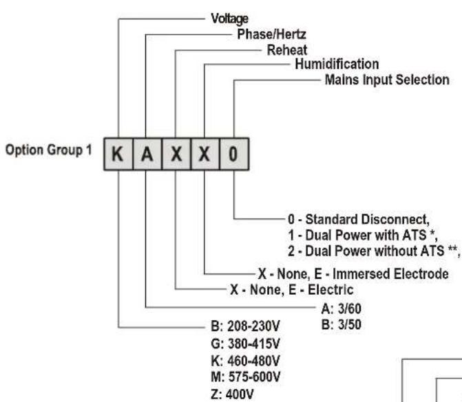
InRoom Nomenclature
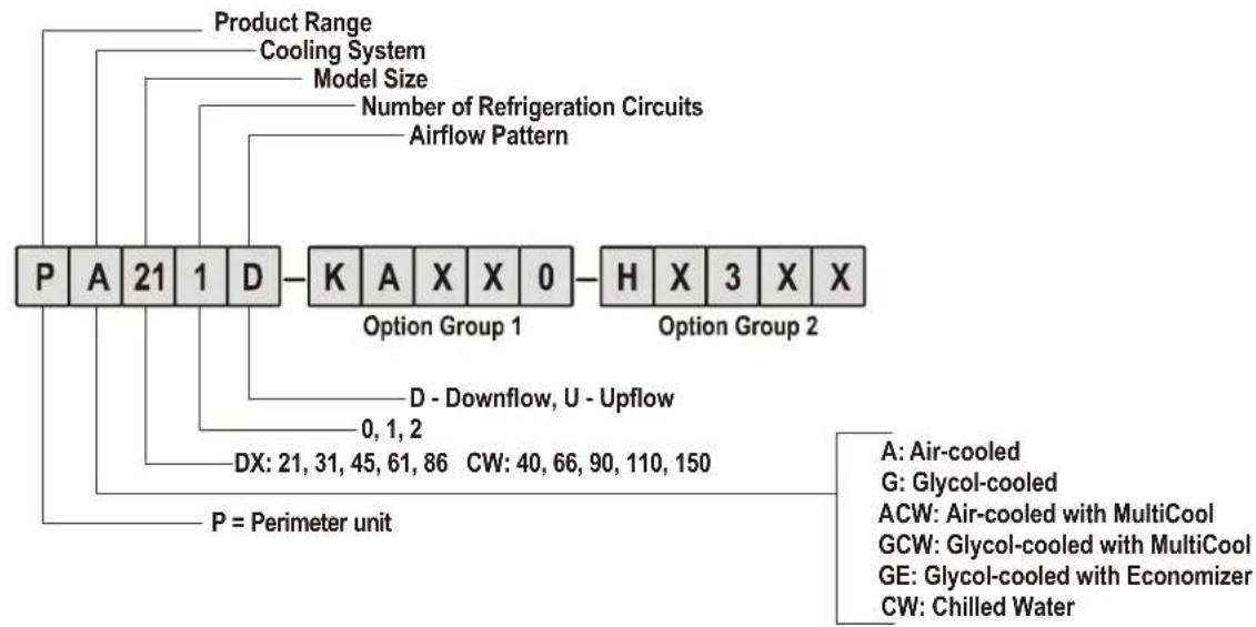
flowchart
graph TD
    A["Product Range"] --> B["Cooling System"]
    B --> C["Model Size"]
    C --> D["Number of Refrigeration Circuits"]
    D --> E["Airflow Pattern"]
    E --> F["K A X X 0"]
    F --> G["Option Group 1"]
    G --> H["H X 3 X X"]
    H --> I["Option Group 2"]
    I --> J["D - Downflow, U - Upflow"]
    J --> K["0, 1, 2"]
    K --> L["P = Perimeter unit"]
    L --> M["DX: 21, 31, 45, 61, 86"]
    M --> N["CW: 40, 66, 90, 110, 150"]
    N --> O["A: Air-cooled"]
    N --> P["G: Glycol-cooled"]
    N --> Q["ACW: Air-cooled with MultiCool"]
    N --> R["GCW: Glycol-cooled with MultiCool"]
    N --> S["GE: Glycol-cooled with Economizer"]
    N --> T["CW: Chilled Water"]
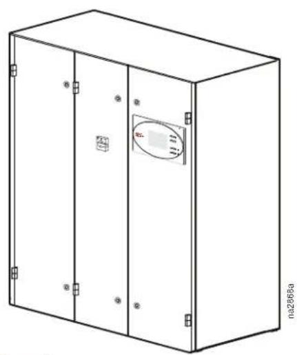
natural_image
Line drawing of a two-port electrical cabinet with a circular vent on top (no text or symbols)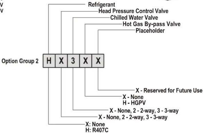
flowchart
graph TD
    A["Option Group 2"] --> B["H"]
    A --> C["X"]
    A --> D["3"]
    A --> E["X"]
    A --> F["X"]
    B --> G["Refrigerant"]
    B --> H["Head Pressure Control Valve"]
    B --> I["Chilled Water Valve"]
    B --> J["Hot Gas By-pass Valve"]
    B --> K["Placeholder"]
    C --> L["X - None, 2 - 2-way, 3 - 3-way"]
    C --> M["X - None, 2 - 2-way, 3 - 3-way"]
    D --> N["X - Reserved for Future Use"]
    D --> O["H - HGPV"]
    F --> P["X: None, H: R407C"]
* Dual Power with ATS - Base Cooling Units without Heat and Humidifier with two Disconnects.
** Dual Power without ATS - Units with Heat and Humidifier with one Disconnect.
ii InRoom Precision AC Tech Data Manual
General
The InRoom product family is an assemble to order (ATO) line of perimeter air conditioning systems that provide precision cooling for data centers and server rooms.
Precision environmental close control requirements now reach far beyond the confines of the traditional data center or computer room to encompass a larger suite of applications, referred to as technology rooms. Critical environment applications include:
- Computer rooms
• Telecommunication facilities - Clean rooms
- Power equipment
• Medical equipment rooms - Archives
• LAN/WAN environments
A worldwide network of APC representatives is fully qualified to provide engineering, sales, installation and service for our products.
APC warrants all parts for 1 year.
Models
The InRoom precision air conditioning unit is available in five sizes. The system is available in both chilled water and direct expansion for a combination of six heat rejection methods.
Select from ACPDX21-86 and ACPCW40-150.
Room Air Distribution
The InRoom downflow system draws warm exhaust air in through the top of the unit and cools it. The cool air is distributed back into the room through a raised floor plenum. These systems are ideal for areas with raised floors greater than 305 mm (10 in) high. Upflow systems draw warm exhaust air in through the front of the unit. The warm exhaust air is then cooled and discharged back into the room through a plenum or ductwork. Upflow systems are ideal for areas without a raised floor, but can also be used in a raised floor environment.
^t The InRoom precision air conditioner delivers high volume airflow to help eliminate hot spots in densely populated environments.
Configurations
• Air Cooled
• Air Cooled with Chilled Water Coil (MultiCool)
- Chilled Water Coil
- Fluid Cooled (Glycol)
- Fluid Cooled (Glycol) with Economizer Cooling Coil
- Fluid Cooled (Glycol) with Chilled Water Coil
Compliance Approval
- ETL/CETL
- NTRL Listed
- Electrical Systems comply with NEC and UL 1995/CSA22.2 No.236

Standard Features
- Insulated Cabinet
- Direct Drive Fans
- Electrical Panel
- Main Power Disconnect Switch
- Refrigeration System with Scroll Compressor and Crankcase Heater (DX only)
- Redundant Group Control
- Network Management Card
- Electronic Expansion Valve (DX only)
- Duct Flange (Upflow only)
- 30% ASHRAE Air Filters
- Brazed plate condenser
- 2 or 3 Way Fluid Regulating Valves (Glycol models)
- 2 or 3 Way Fluid Regulating Valves (CW only)
- Discrete Input/Output Interface
- Resettable Circuit Breakers
- Microprocessor Controller
- Graphical User Interface
- Electrically Commutated (EC) Fans
- Stainless Steel Condensate Pan
- Automatic Transfer Switches
Optional Features
- Plenum
- Sub-base Plenum
- Floorstand
- Seismic Floorstand
- Immersed Electrode Humidifier
- Condensate Pump
- Electric Heat
- Spot Water Detector(s)
- Cable Water Detector(s) (60 Hz only)
- Smoke Detector
- Hot Gas Bypass Valve
Scalable Solution for Critical Environments
Temperature and Humidity Design Conditions
Maintenance of temperature and humidity design conditions is critical to the smooth operation of a technology room. Based on ASHRAE TC9.9, the recommended design conditions for class one and class two environments should be 20–25°C (68–77°F) and 40–55% relative humidity (R.H.). Precision air conditioning is designed to maintain temperature at ±2°F and humidity at ±3–5% R.H. 24 hours a day, 365 days a year. Vapor barriers and sealed rooms are required to maintain these tolerances. In contrast, comfort systems are designed to maintain ±5°F from the temperature setpoint. There is usually no dedicated humidity control and the simple controllers cannot maintain the setpoint tolerance required for temperature, allowing potentially harmful temperature and humidity swings to occur. This is not acceptable for sensitive electronic equipment.
Air Quality
Precision air conditioners provide a high volume of air flow, around 600 CFM/ton (286 L/m, 150 CFM/kW). This high CFM moves more air through the space improving air distribution and reducing the chance of localized hot spots. It also allows more air to move through filters, ensuring a cleaner environment. This requires a moderate-to high-efficiency filter bank to minimize airborne particles.
Low Humidity
Low humidity greatly increases the possibility of static electric discharges. Static discharges can corrupt data and damage hardware.
High Humidity
High humidity can result in tape surface deterioration, head crashes, condensation, corrosion, paper handling problems and gold and silver migration leading to component and board failure.
High & Low Temperature
A high or low temperature or rapid temperature swings can corrupt data processing and shut down an entire system. Temperature variations can alter the electrical and physical characteristics of electronic chips and other board components causing faulty operation or failure. These problems may be transient or may last for days. Transient problems can be very difficult to diagnose and repair.
Efficiency and Reliability
The use of energy efficient, direct drive fans along with fewer moving internal parts eliminate most potentials for failure. Scroll compressor technology provides unparalleled efficiency and constant, reliable operation with an ability to withstand liquid refrigerant ‘slugging’ which is a major cause of compressor failure. The compressor is also equipped with an internal high pressure sensor which opens a bypass valve in case of high pressure. This ensures internal pressure compensation takes place and damage to the compressor is avoided.
APC InRoom - The Right Solution
The APC InRoom cooling unit provides the maximum amount of precision cooling in a compact footprint with the lowest operating cost and noise level.
Dedicated Dehumidification Cycle
A dedicated dehumidification cycle allows the system to increase latent capacity without boosting compressor capacity, and also lowers the requirement for reheat. To achieve dehumidification, the electronic expansion valve is first partially closed. The reduction of the refrigerant mass flow makes the evaporation temperature drop, which lets the surface temperature in a part of the evaporator fall below the dew point of the air, causing dehumidification. For increased dehumidification, the fan speed is reduced. With a constant cooling capacity, the temperature of the air which flows through the heat exchanger coil passes below the dew point. The moisture contained in the air condenses on the heat exchanger, gathers in the condensate pan, and is carried away by the drain. To achieve humidification for the DX units with cabinet size 1 and all CW units, the fan speed is reduced. For the DX units with cabinet size 2–5, approximately one third of the evaporator is isolated from the refrigerant flow by a solenoid valve to achieve dehumidification by lowering the evaporator temperature below the dew point.
Standard Features
Insulated Panels
The frame is constructed of 16 gauge steel sheet metal for maximum strength. All exterior panels and corner posts on the frame are powder coated for durability and an attractive finish. The side panels are double wall construction (inner and outer panels) with insulation between. The insulation is 12 mm (1/2 in) thick fiberglass. The walls isolate the insulation from the air stream and further reduce sound levels. Panels are hinged and removable for easy access. The cabinet is serviceable from the front of the unit.
Electronically Commutated (EC) Fans
Each unit is equipped with electronically commutated (EC) fan modules. This technology increases fan efficiency by up to 30% while reducing operating costs. Each fan module has an anti-vibration mounting to isolate it from the unit structure.
Electrical Panel
The electrical panel contains the contactors, starters, overload protection devices, and input power disconnects.
Main Power Disconnect Switch
A main power disconnect switch disconnects all high voltage power to the unit if necessary. The disconnect switch is accessible without removing the electric box cover.
Network Management Card
Permits multi-level access to monitoring, control, and event notification features over the building management network.
Refrigeration System and Compressor
The refrigeration system operates under a master controller for greater efficiency and accuracy. Suction and discharge pressures (DX models) are monitored and electronically controlled. The scroll compressors are designed for year-round operation with a 15-year life expectancy. The controller microprocessor provides real-time suction and discharge pressure readings reported by transducers installed on the refrigeration system.
For compressor protection, the InRoom precision air conditioner utilizes charge isolation and crank case heaters during off cycles (DX only). This eliminates the threat of liquid refrigerant migration that could lead to compressor slugging and lubrication issues.
Mains Automatic Transfer Switches
Mains automatic transfer switches allow two power sources to be connected to the cooling unit. A secondary power source (generator or UPS) can be automatically transferred in the event of a failure of the main power source to maintain cooling. Programmable switches are voltage adjustable with On and Off delay which can be adjusted from 0 to 20 seconds. The Off delay should be set to 3 seconds. Contact customer support for assistance to determine your requirements.
Duct Flange
A 25 mm (1 in) duct flange is included for the upflow units to provide convenient connection to external ductwork for either supply or return air as needed.
Evaporative Freeze Protection
Suction pressure is actively monitored by two individual sensors and controlled by the microprocessor controller to calculate the opening of the electronic expansion valve, eliminating the risk of condensate freeze-up on the evaporator coil.
Redundant Group Control
Allows up to 16 units to communicate with each other for redundancy, demand fighting prevention, and mode assist. Global sharing of certain settings requires a twisted pair shielded wiring interconnection.
30% ASHRAE 52.1 Filters
The filtration of conditioned air is extremely vital to maintaining the clean, particle-free environment required by electrical equipment. The system uses 30% (100 micron) filters, with full depth filter pleats. Deeper filters produce a lower pressure drop, requiring less energy during normal operation. Filters are replaceable through the front of the upflow unit and through the top of the downflow unit.
Condenser (Direct Expansion units only)
Standard air cooled condensers are suitable for cooling up to the maximum ambient temperature of either 35^ C ( 95^ F) or 46.1^ C ( 115^ F) depending on the requirement. These condensers have variable fan speed controls to allow operation down to -28.9^ C ( -20^ F).
Optional Features
Humidifier
The humidifier utilizes a pure steam generator specifically designed for precision environmental close control. The pure steam eliminates contaminating mineral deposits, potentially harmful bacteria, white dust, and excessive humidity. The humidifier requires little scheduled maintenance. The humidifier is proportionally controlled to meet the humidification demands of the conditioned space. Humidifier canisters are replaceable.
Electric Reheat
Electric reheat elements are low watt density, wired for 3-phase and loaded equally on all three phases, SCR controlled, and electrically and thermally protected by both automatic and manual reset thermal cut outs. Reheat coils are stainless steel, tubular fin construction.
Spot Water Detector
The solid-state spot water detector is available for both 50 and 60 Hz cooling units. The spot water detector activates an audible alarm on the controller when moisture is detected.
Smoke Detector
The factory-installed smoke detector is designed to sense smoke in the return air stream. Upon detection of smoke, an audible and visual alarm on the microprocessor controller will be activated and the unit will be shut down immediately.
Hot Gas Bypass Valve
The hot gas bypass valve (HGBV) adjusts the flow of compressor discharge gas to the evaporator coil at low load conditions to protect the coil from freezing and the compressor from excessive cycling. 60 Hz cooling units use a mechanical HGBV. 50 Hz cooling units use an electronically controlled HGBV. On 50 Hz cooling units, the HGBV option requires the analog extension board EAIO.
Cable Leak Detector (60 Hz only)
The optional 6 m (20 ft) leak detection sensing cable (APC part number ACAC75105) is available for 60 Hz cooling units only. The cable leak detector is placed on the floor or subfloor around all possible leak sources. If water or other conductive liquids contact the cable anywhere along its length, the master controller visually and audibly announces the leak.
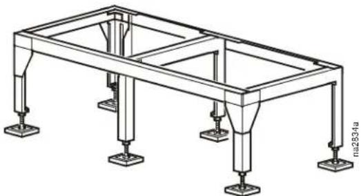
Floorstand
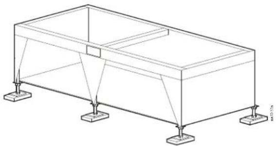
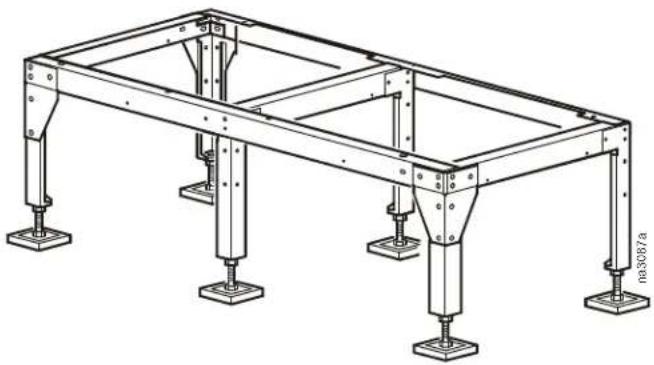
The floorstand raises the unit above the subfloor to match the height of the raised floor. Heights are available from 254 mm (10 in) to 610 mm (24 in) in 76.2 mm (3 in) increments and are adjustable +/- 38.1 mm (1.5 in). Adjustment is provided by threaded pedestals. Vibration-absorbing pads are included. The floorstand, pedestal, and pads ship loose. In areas where earthquakes are a concern, seismic floorstands are available in 305 mm (12 in), 457 mm (18 in), and 610 mm (24 in) heights.
Plenums
Discharge plenums are available on upflow configurations. This application is recommended in rooms where raised floors are not available for air distribution. Discharge air should be ducted down cold aisles.
Base Plenum
Insulated base plenums are available for downflow cooling units where raised floors are not available for air distribution. Four front-discharge configurations are available equipped with dampers, grilles, flexible ductwork or open. All configurations are 450 mm (17.7 in) high and sit beneath the InRoom cooling unit.
Water Regulating Valves
Water and fluid cooled systems utilize two- or three-way valves to regulate the amount of water or glycol supplied to the condenser in response to refrigerant discharge pressure. The standard valve pressure rating is 28 kPa (400 psi).
Extreme Low Temperature Kit (Direct Expansion units only)
Extreme Low Temperature Kits for air cooled condensers are available for operation below -34.4^ ( -30^ ). The optional kit consists of pressure control valves and receivers for the liquid return side of the refrigerant piping.
Condensate Pump
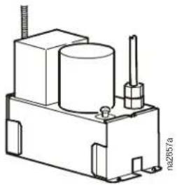
natural_image
Technical line drawing of a mechanical component with no visible text or symbols60 Hz
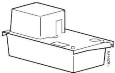
natural_image
Technical line drawing of a rectangular electronic component with mounting holes and a side outlet (no text or symbols)50 Hz
| Model # ACAC75107 ACAC75107 ACAC76106 | |||
| Hz 60 60 50 | |||
| Height mm (in) 259 (10 1/8) | 259 (10 1/8) 210 (8 1/4) | ||
| Width mm (in) 152 (6) 152 (6) 132 (5 1/4) | |||
| Length 304 (12) 304 (12) 295 (11 1/2) | |||
| Outlet mm (in) 13 (1/2) 13 (1/2) 6 (1/4) | |||
| Volts | 230 | 460 | 400 |
| Amps | 1.9 | 0.8 | 0.125 |
| Watts | 360 | 360 | 30 |
| Weight Kg (Lb) Ea | 5.8 (13) | 5.8 (13) | 3 (6.6) |
| HP (motor only) | 1/5 | 1/5 | 1/20 |
| Tank Capacity Ltr (Gal) | 3.785 (1) | 3.785 (1) | 1.4 (1/3) |
| Model | Liters (Gallons) per hour at 60 Hz/Rated Voltage Flow rate per pressure drop | ||||||
| 1 ft | 5 ft | 10 ft | 15 ft | 20 ft | 30 ft | 40 ft | |
| ACAC75107 | 1839 (486) | 1714 (453) | 1559 (412) | 1407 (372) | 1275 (337) | 942 (249) | 635 (168) |
| ACAC75108 | 1589 (420) | 1438 (380) | 1343 (355) | 1248 (330) | 1173 (310) | 908 (240) | 548 (145) |
| Model | Liters (Gallons) per hour at 50 Hz/Rated Voltage - Flow rate per pressure drop | |||
| 1 m | 2 m | 3 m | 4 m | |
| ACAC76106 | 135 (35.5) | 100 (26.4) | 60 (15.8) | 20 (5.3) |
Upflow Discharge Plenums for 50 Hz and 60 Hz InRoom Cooling Units
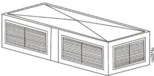
natural_image
Isometric line drawing of a two-story rectangular structure with ventilation grilles and diagonal roof lines (no text or symbols)| Upflow discharge plenums | ||||
| Cabinet size SKU | Width mm (in) | Depth mm (in) | Height mm (in) | |
| 1 ACPL75100 1000 (39.37) | 900 (35) 500 (19.7) | |||
| 2 ACPL75101 1400 (55.11) | ||||
| 3 ACPL75102 1750 (68.90) | ||||
| 4 ACPL75103 2150 (84.65) | ||||
| 5 ACPL75104 2550 (100.39) | ||||

Note: Plenums are delivered completely assembled.
Downflow Discharge Plenums for 50 Hz InRoom Cooling Units
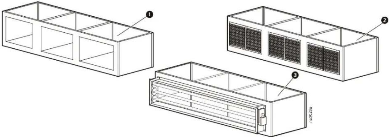
natural_image
Technical line drawing of three rectangular industrial storage units with internal compartments and ventilation grilles (no text or symbols)| Cabinet size SKU | Width mm (in) | Depth mm (in) | Height mm (in) |
| 1 Unit Sub Base Plenum with no Grills | |||
| 1 ACSB76100 960 (37.8) | 865 (34) 450 (17.7) | ||
| 2 ACSB76101 1360 (53.5) | |||
| 3 ACSB76102 1710 (67.3) | |||
| 4 ACSB76103 2110 (83.1) | |||
| 5 ACSB76104 2510 (98.8) | |||
| 2 Unit Sub Base Plenum with Grills | |||
| 1 ACSB76110 960 (37.8) | 865 (34) 450 (17.7) | ||
| 2 ACSB76111 1360 (53.5) | |||
| 3 ACSB76112 1710 (67.3) | |||
| 4 ACSB76113 2110 (83.1) | |||
| 5 ACSB76114 2510 (98.8) | |||
| 3 Unit Sub Base Plenum with Damper (50Hz only) | |||
| 1 ACSB76120 960 (37.8) | 865 (34) 450 (17.7) | ||
| 2 ACSB76121 1360 (53.5) | |||
| 3 ACSB76122 1710 (67.3) | |||
| 4 ACSB76123 2110 (83.1) | |||
| 5 ACSB76124 2510 (98.8) | |||
| Unit Sub Base Plenum with Flex Connector (not shown) | |||
| 1 ACSB76130 960 (37.8) | 865 (34) 450 (17.7) | ||
| 2 ACSB76131 1360 (53.5) | |||
| 3 ACSB76132 1710 (67.3) | |||
| 4 ACSB76133 2110 (83.1) | |||
| 5 ACSB76134 2510 (98.8) | |||

Note:
- All three sub-base plenum models are attached to the cooling unit with 4x M10 screws.
- Sub-base plenums with grills ② are equipped with adjustable horizontal fins to direct exiting air.
- The plenums can be installed with the opening to the front or with the opening to the rear.
natural_image
Technical line drawing of a structural frame with supports and legs (no text or symbols)| Cabinet size Model | Height mm (in) | Width mm (in) | Depth mm (in) | |
| 1 | ACFS76000 254 | (10) 960 (37.8) | 864 (34) | |
| ACFS76001 305 | (12) | |||
| ACFS76002 381 | (15) | |||
| ACFS76003 457 | (18) | |||
| ACFS76004 609 | (24) | |||
| 2 | ACFS76005 254 | (10) 1359 (53.5) | 864 (34) | |
| ACFS76006 305 | (12) | |||
| ACFS76007 381 | (15) | |||
| ACFS76008 457 | (18) | |||
| ACFS76009 609 | (24) | |||
| 3 | ACFS76010 254 | (10) 1712 (67.4) | 864 (34) | |
| ACFS76011 305 | (12) | |||
| ACFS76012 381 | (15) | |||
| ACFS76013 457 | (18) | |||
| ACFS76014 609 | (24) | |||
| 4 | ACFS76015 254 | (10) 2108 (83.0) | 864 (34) | |
| ACFS76016 305 | (12) | |||
| ACFS76017 381 | (15) | |||
| ACFS76018 457 | (18) | |||
| ACFS76019 609 | (24) | |||
| 5 | ACFS76020 254 | (10) 2512 (98.9) | 864 (34) | |
| ACFS76021 305 | (12) | |||
| ACFS76022 381 | (15) | |||
| ACFS76023 457 | (18) | |||
| ACFS76024 609 | (24) | |||
Bowling Alley Floorstands for InRoom 60Hz Cooling Units
natural_image
Isometric line drawing of a rectangular structural frame with supports at both ends (no text or symbols)| Cabinet size Model | Height mm (in) | Width mm (in) | Depth mm (in) | |
| 1 | ACFS76033 305 (12) | 960 (37.8) 864 (34) | ||
| ACFS76032 381 (15) | ||||
| ACFS76031 457 (18) | ||||
| ACFS76030 609 (24) | ||||
| 2 | ACFS76037 305 (12) | 1359 (53.5) 864 (34) | ||
| ACFS76036 381 (15) | ||||
| ACFS76035 457 (18) | ||||
| ACFS76034 609 (24) | ||||
| 3 | ACFS76041 305 (12) | 1712 (67.4) 864 (34) | ||
| ACFS76040 381 (15) | ||||
| ACFS76039 457 (18) | ||||
| ACFS76038 609 (24) | ||||
| 4 | ACFS76045 305 (12) | 2108 (83.0) 864 (34) | ||
| ACFS76044 381 (15) | ||||
| ACFS76043 457 (18) | ||||
| ACFS76042 609 (24) | ||||
| 5 | ACFS76049 305 (12) | 2512 (98.9) 864 (34) | ||
| ACFS76048 381 (15) | ||||
| ACFS76047 457 (18) | ||||
| ACFS76046 609 (24) | ||||
Floorstands for InRoom 50 HzCooling Units
natural_image
Technical line drawing of a structural frame with four vertical supports and mounting feet (no text or symbols)| Cabinet size Model | Height mm (in) | Width mm (in) | Depth mm (in) |
| 1 ACFS76025 250-500 (10-20) 960 | (37.8) 864 (34) | ||
| 2 ACFS76026 250-500 (10-20) 135 | (53.5) 864 (34) | ||
| 3 ACFS76027 250-500 (10-20) 171 | (67.4) 864 (34) | ||
| 4 ACFS76028 250-500 (10-20) 210 | (83.0) 864 (34) | ||
| 5 ACFS76029 250-500 (10-20) 251 | (98.9) 864 (34) |
Condensers
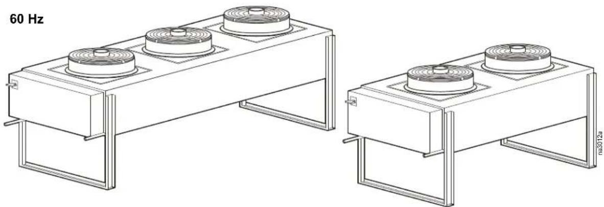
Air cooled condensers are designed to reject heat from refrigerant based cooling equipment and are designed to be installed outdoors. The condensers are self-contained in a lightweight aluminum cabinet designed for mounting to a horizontal surface. The cabinet houses condenser coils and fan assemblies. Each condenser coil is a copper turb, aluminum finned coil.
The capacity of the condenser is based on the rated capacity of the coil. In the case of dual circuit units, the model number is based on the combined capacity of both coils. The coil is a closed-loop refrigerant condensing heat exchanger in which refrigerant is continuously circulated by the pressure differential created by a compressor.
The compressor increases refrigerant pressure to a level sufficiently high for it to be cooled and condensed into liquid by the effect of ambient air being drawn over the condenser coil. The fans have corrosion resistant, multi-blade impellers designed for high aerodynamic efficiency which results in lower power consumption, lower noise levels and longer life. Each fan utilizes a direct driven motor with maintenance free bearings. The fan motors are internally protected from overload. Fans have finger guard grilles to protect operators from injury and keep large tools or other objects from falling into the fan.
Electrical controls are in a weather proof enclosure and isolated from the rest of the equipment. The electrical box has a removable front access panel which is safety interlocked with the service disconnect switch, preventing the panel from being removed when the switch is in the ON position. The switch must be turned off to gain access to the electrical components.
natural_image
Technical line drawing of two industrial heat exchangers with circular heat sinks, no text or symbols present| InRoom Remote Outdoor Condenser Data, 95°F ambient, 120°F condensation - R407C | |||||
| InRoom Cabinet Size 1 2 3 4 5 | |||||
| Total Heat Rejection (THR) BTU/h | 96.219 165. | 496 225.435 279.2 | 62 380.436 | ||
| CFM 8,394 19,325 18,609 | 17,604 27,963 | ||||
| Fan Diameter - in | 19.69 | 24.80 | 24.80 | 24.80 | 24.80 |
| Voltage Options | |||||
| 208-230/3/60 | ACCD76000 | ACCD76004 | ACCD76008 | ACCD76012 | ACCD76016 |
| Number of Fans | 2 2 2 2 3 | ||||
| Fan RPM (Qty) | 1490 | 1585(1), 1500(1) | 1585(1), 1500(1) | 1585(1), 1500(1) | 1585(2), 1500(1) |
| Motor HP (Qty) | 1.23 Hp(2) | 3.58(1), 3.85(1) | 3.58(1), 3.85(1) | 3.58(1), 3.85(1) | 3.58(2), 3.85(1) |
| Electrical Data | |||||
| FLA | 8.6 | 19.7 | 19.7 | 19.7 | 29.1 |
| MCA | 9.8 | 22.1 | 22.1 | 22.1 | 31.5 |
| MFS | 15 | 30 | 30 | 30 | 40 |
| 460-480/3/60 | ACCD76010 | ACCD76005 | ACCD76009 | ACCD76013 | ACCD76017 |
| Number of Fans | 2 2 2 2 3 | ||||
| Fan RPM (Qty) | 1450(1), 1570(1) | 1650(1), 1500(1) | 1650(1), 1500(1) | 1650(1), 1500(1) | 1650(2), 1500(1) |
| Motor HP (Qty) | 1.34(1), 1.64(1) | 3.90(1), 3.85(1) | 3.90(1), 3.85(1) | 3.90(1), 3.85(1) | 3.90(2), 3.85(1) |
| Electrical Data | |||||
| FLA | 3.9 | 9.5 | 9.5 | 9.5 | 14.57 |
| MCA | 4.3 | 10.7 | 10.7 | 10.7 | 15.85 |
| MFS | 15 | 15 | 15 | 15 | 20 |
| 575-600/3/60 | ACCD76022 | ACCD76023 | ACCD76024 | ACCD76025 | ACCD76026 |
| Number of Fans | 2 2 2 2 3 | ||||
| Fan RPM (Qty) | 1450(1), 1570(1) | 1650(1), 1500(1) | 1650(1), 1500(1) | 1650(1), 1500(1) | 1650(2). 1500(1) |
| Motor HP (Qty) | 1.34(1), 1.64(1) | 3.90(1), 3.85(1) | 3.90(1), 3.85(1) | 3.90(1), 3.85(1) | 3.90(2), 3.85(1) |
| Electronic Data | |||||
| FLA | 3.4 | 8.0 | 8.0 | 8.0 | 12.3 |
| MCA | 37 | 9.0 | 9.0 | 9.0 | 13.4 |
| MFS | 15.0 | 15.0 | 15.0 | 15.0 | 15.0 |
| Refrigerant Connections* | |||||
| Hot Gas Line - in | 1 1/8 OD | 1 1/8 OD | 1 3/8 OD | 1 3/8 OD | 1 5/8 OD |
| Liquid Line - in | 7/8 OD | 7/8 OD | 1 1/8 OD | 1 1/8 OD | 1 3/8 OD |
| Physical Data** | |||||
| Dimensions -HxWxD in | 35.5x32.75x76 | 48x108.5x48.25 | 48x108.5x48.25 | 48x108.5x48.25 | 48x155.5x48.25 |
| Approximate Weight - lb. | 240 | 455 | 495 | 555 | 835 |
* Condenser connections may not represent actual line sizing.
** Dimensions are overall. Electrical enclosure and fan guard are included. Actual fan guard height is 4 in. Actual electrical enclosure depth is 6.5 in.
| InRoom Remote Outdoor Condenser Data, 95°F ambient, 120°F condensation - R407C | |||||
| InRoom Cabinet Size 1 2 3 4 5 | |||||
| Total Heat Rejection (THR) BTU/h | 96.219 165. | 496 225.435 279.2 | 62 380.436 | ||
| CFM 8,394 19,325 18,609 | 17,604 27,963 | ||||
| Fan Diameter - in | 19.69 | 24.80 | 24.80 | 24.80 | 24.80 |
| Voltage Options | |||||
| 208-230/3/60 | ACCD76032 | ACCD76033 | ACCD76034 | ACCD76035 | ACCD76036 |
| Number of Fans | 2 2 2 2 3 | ||||
| Fan RPM (Qty) | 1490 | 1585(1), 1500(1) | 1585(1), 1500(1) | 1585(1), 1500(1) | 1585(2), 1500(1) |
| Motor HP (Qty) | 1.23(2) | 3.58(1), 3.85(1) | 3.58(1), 3.85(1) | 3.58(1), 3.85(1) | 3.58(2), 3.85(1) |
| Electrical Data | |||||
| FLA | 8.6 | 19.7 | 19.7 | 19.7 | 29.1 |
| MCA | 9.8 | 22.1 | 22.1 | 22.1 | 31.5 |
| MFS | 15 | 30 | 30 | 30 | 40 |
| 460-480/3/60 | ACCD76037 | ACCD76038 | ACCD76039 | ACCD76040 | ACCD76041 |
| Number of Fans | 2 2 2 2 3 | ||||
| Fan RPM (Qty) | 1450(1), 1570(1) | 1650(1), 1500(1) | 1650(1), 1500(1) | 1650(1), 1500(1) | 1650(2), 1500(1) |
| Motor HP (Qty) | 1.34(1), 1.64(1) | 3.90(1), 3.85(1) | 3.90(1), 3.85(1) | 3.90(1), 3.85(1) | 3.90(2), 3.85(1) |
| Electrical Data | |||||
| FLA | 3.9 | 9.5 | 9.5 | 9.5 | 14.57 |
| MCA | 4.3 | 10.7 | 10.7 | 10.7 | 15.85 |
| MFS | 15 | 15 | 15 | 15 | 20 |
| 575-600/3/60 | ACCD76042 | ACCD76043 | ACCD76044 | ACCD76045 | ACCD76046 |
| Number of Fans | 2 2 2 2 3 | ||||
| Fan RPM (Qty) | 1450(1), 1570(1) | 1650(1), 1500(1) | 1650(1), 1500(1) | 1650(1), 1500(1) | 1650(2 ), 1500(1) |
| Motor HP (Qty) | 1.34(1), 1.64(1) | 3.90(1), 3.85(1) | 3.90(1), 3.85(1) | 3.90(1), 3.85(1) | 3.90(2), 3.85(1) |
| Electronic Data | |||||
| FLA | 3.7 | 8.3 | 8.3 | 8.3 | 12.8 |
| MCA | 4.0 | 9.3 | 9.3 | 9.3 | 13.9 |
| MFS | 15.0 | 15.0 | 15.0 | 15.0 | 15.0 |
| Low Ambient Kit | ACCD76106 | ACCD76107 | ACCD76109(2) | ACCD76106(2) | ACCD76107(2) |
| Refrigerant Connections* | |||||
| Hot Gas Line - in | 1 1/8 OD | 1 1/8 OD | 1 3/8 OD | 1 3/8 OD | 1 5/8 OD |
| Liquid Line - in | 7/8 OD | 7/8 OD | 1 1/8 OD | 1 1/8 OD | 1 3/8 OD |
| Physical Data** | |||||
| Dimensions -HxWxD in | 35.5x32.75x76 | 48x108.5x48.25 | 48x108.5x48.25 | 48x108.5x48.25 | 48x155.5x48.25 |
| Approximate Weight - lb. | 240 | 455 | 495 | 555 | 835 each |
* Condenser connections may not represent actual line sizing.
** Dimensions are overall. Electrical enclosure and fan guard are included. Actual fan guard height is 4 in. Actual electrical enclosure depth is 6.5 in.
| InRoom Remote Outdoor Condenser Data, 105°F ambient, 125°F condensation - R407C | |||||
| InRoom Cabinet Size 1 2 3 4 5 | |||||
| Total Heat Rejection (THR) BTU/h | 154,105 247, | 501 331,845 448,6 | 00 331,845 (2) | ||
| CFM 19,325 17,604 27,791 | 25,227 27,791 (2) | ||||
| Fan Diameter - in | 25.60 | 25.60 | 25.60 | 25.60 | 25.60 |
| Voltage Options | |||||
| 208-230/3/60 | ACCD76004 | ACCD76006 | ACCD76016 | ACCD76014 | ACCD76020(2) |
| Number of Fans | 2 2 3 3 3 | ||||
| Fan RPM (Qty) | 1585(1), 1500(1) | 1585(1), 1500(1) | 1585(2), 1500(1) | 1585(1), 1350(1) | 1585(2), 1500(1) |
| Motor HP (Qty) | 3.58(1), 3.85(1) | 3.58(1), 3.85(1) | 3.58(2), 3.85(1) | 3.58(2), 3.75(1) | 3.58(2), 3.75(1) |
| Electrical Data | |||||
| FLA | 19.7 | 19.7 | 29.1 | 29.1 | 29.1 |
| MCA | 22.1 | 22.1 | 31.5 | 31.5 | 31.5 |
| MFS | 30 | 30 | 40 | 40 | 40 |
| 460-480/3/60 | ACCD76005 | ACCD76007 | ACCD76017 | ACCD76015 | ACCD76021(2) |
| Number of Fans | 2 2 3 3 3 | ||||
| Fan RPM (Qty) | 1650(1), 1500(1) | 1650(1), 1500(1) | 1650(2), 1500(1) | 1650(2), 1350(1) | 1650(2), 1500(1) |
| Motor HP (Qty) | 3.90(1), 3.85(1) | 3.90(1), 3.85(1) | 3.90(2), 3.85(1) | 3.90(2), 3.75(1) | 3.90(2), 3.85(1) |
| Electrical Data | |||||
| FLA | 9.5 | 9.5 | 14.57 | 14.57 | 14.57 |
| MCA | 10.7 | 10.7 | 15.85 | 15.85 | 15.85 |
| MFS | 15 | 15 | 20 | 20 | 20 |
| 575-600/3/60 | ACCD76027 | ACCD76028 | ACCD76029 | ACCD76030 | ACCD76031(2) |
| Number of Fans | 2 2 3 3 3 | ||||
| Fan RPM (Qty) | 1650(1), 1500(1) | 1650(1), 1500(1) | 1650(2), 1500(1) | 1650(2), 1350(1) | 1660(2), 1500(1) |
| Motor HP (Qty) | 3.90(1), 3.85(1) | 3.90(1), 3.85(1) | 3.90(2), 3.85(1) | 3.90(2), 3.75(1) | 3.90(2), 3.85(1 |
| Electrical Data | |||||
| FLA | 8.0 | 8.0 | 12.3 | 12.3 | 12.3 (2) |
| MCA | 9.0 | 9.0 | 13.4 | 13.4 | 13.4 (2) |
| MFS | 15.0 | 15.0 | 15.0 | 15.0 | 15.0 |
| Refrigerant Connections* | |||||
| Hot Gas Line - in | 1 1/8 OD | 1 5/8 OD | 1 5/8 OD | 1 5/8 OD | 2 1/8 OD |
| Liquid Line - in | 7/8 OD | 1 3/8 OD | 1 3/8 OD | 1 3/8 OD | 2 1/8 OD |
| Physical Data** | |||||
| Dimensions -HxWxD in | 48x108.5x48.25 | 48x108.5x48.25 | 48x155.5x48.25 | 48x155.5x48.25 | 48x155.5x48.25 |
| Approximate Weight - lb. | 455 | 555 | 835 | 1000 | 835 (2) |
* Condenser connections may not represent actual line sizing.
** Dimensions are overall. Electrical enclosure and fan guard are included. Actual fan guard height is 4 in. Actual electrical enclosure depth is 6.5 in.
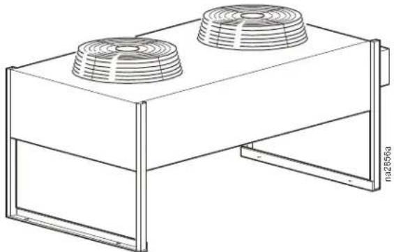
50 Hz
natural_image
Technical line drawing of a rectangular industrial or cooling unit with two circular fans (no text or symbols)| InRoom Remote Outdoor Condenser Data, 97°F ambient, 120°F condensation - R407C | |||||
| InRoom Cabinet Size 1 | 2 3 4 5 | ||||
| Condenser Model (Qty) | ACCD76002 ACCD76003 ACCD76002 (2) ACCD76003 (2) ACCD76011(2) | ||||
| Voltage 230/1/50 230/1/50 230/1/50 230/1/50 230/1/50 | |||||
| Number of Fans 2 2 3 3 3 | |||||
| Airflow m3/h (cfm) | 13600 (8024) | 13000 (7670) | 13600 (8024) each | 13000 (7670) each | 16800 (9912) each |
| Motor kW (HP) - | 2 x 0.69(2 x 0.92) | 2 x 0.69(2 x 0.92) | 2 x 0.69(2 x 0.92) | 2 x 0.69(2 x 0.92) | 3 x 0.69(3 x 0.92) |
| Refrigerant Connections* | |||||
| Hot Gas Line - in | 7/8 OD | 7/8 OD | 7/8 OD | 1 3/8 OD | 7/8 OD |
| Liquid Line - in | 7/8 OD | 7/8 OD | 7/8 OD | 7/8 OD | 7/8 OD |
| Weight - kg (lb) | 72 (158) | 81 (178) | 2 x 72 (2 x 158) | 2 x 81 (2 x 178) | 2 x 144 (2 x 317) |
| InRoom Remote Outdoor Condenser Data, 115°F ambient, 131°F condensation - R407C | |||||
| Condenser Model (Qty) | ACCD76003 ACCD76011 ACCD76001 (2) ACCD76011 (2) ACCD76019(2) | ||||
| Voltage 230/1/50 230/1/50 230/1/50 230/1/50 230/1/50 | |||||
| Number of Fans 2 2 3 3 3 | |||||
| Airflow m3/h (cfm) | 13000 (7670) | 16800 (9912) | 13000 (7670) each | 16800 (9912) each | 24000 (14160) each |
| Motor kW (HP) - | 2 x 0.69(2 x 0.92) | 3 x 0.69(3 x 0.92) | 2 x 0.69(2 x 0.92) | 2 x 0.69(2 x 0.92) | 3 x 0.62(3 x 0.83) |
| Refrigerant Connections* | |||||
| Hot Gas Line - in | 7/8 OD | 7/8 OD | 7/8 OD | 7/8 OD | 1 3/8 OD |
| Liquid Line - in | 7/8 OD | 7/8 OD | 7/8 OD | 7/8 OD | 7/8 OD |
| Weight - kg (lb) | 81 (178) | 144 (317) | 2 x 81 (2 x 178) | 2 x 144 (2 x 317) | 2 x 200 (2 x 440) |
* Condenser connections may not represent actual line sizing.
Receivers
Conformance. Each receiver conforms to UL, CSA or ASME requirements for 450 psi maximum working pressure. Models with an internal diameter under six inches are UL listed. All larger models are made according to ASME code and labeled appropriately.
Pumpdown and refrigerant charge. All pumpdowns are calculated at 80% capacity of liquid. Approximately 10% of pumpdown capacity is required to operate the receiver properly.
Pumpdown = (overall length - length correction) x (pumpdown per inch) Overall length = (pumpdown required / pumpdown per inch) = (length correction)
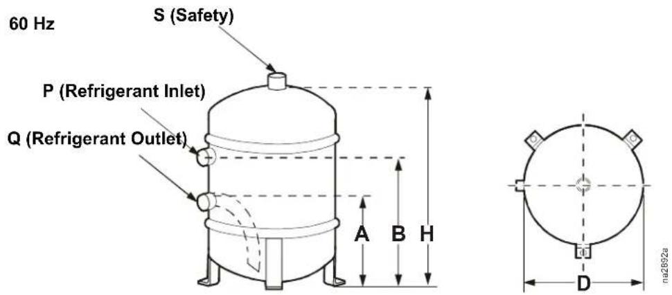
| InRoom Cabinet Size 1 2 3 4 | 5 | ||||
| 60 Hz Air-Cooled Condenser Model | ACCD76032 | ACCD76033 | ACCD76034 | ACCD76035 | ACCD76036 |
| ACCD76037 | ACCD76038 | ACCD76039 | ACCD76040 | ACCD76041 | |
| ACCD76042 | ACCD76043 | ACCD76044 | ACCD76045 | ACCD76046 | |
| 60 Hz Receiver Model (Qty) | ACAC76106 | ACAC76107 | ACAC76109 (2) | ACAC76106 (2) | ACAC76107 (2) |
| Pumpdown capacities for R-407C kg (lb) * | 11.79 (26) | 19.58 (44) | 8.1 (18) each | 11.79 (26) each | 27.7 (61) each |
| Length correction mm (in) | 45.7 (1.8) | 58.4 (2.3) | 45.7 (1.8) | 45.7 (1.8) | 66 (2.6) |
| End to weld mm (in) | 79.4 (3 1/8) | 114.3 (4 1/2) | 79.4 (3 1/8) | 79.4 (3 1/8) | 139.7 (5 1/2) |
| D (OD) mm (in) | 219 (8 5/8) | 273 (10 3/4) | 219 (8 5/8) | 219 (8 5/8) | 324 (12 3/4) |
| H mm (in) | 406.4 (16) | 457.2 (18) | 304.8 (12) | 406.4 (16) | 457.2 (18) |
| A mm (in) | 127 (5) | 152.4 (6) | 127 (5) | 127 (5) | 168.2 (6 5/8) |
| B mm (in) | 279.4 (11) | 292.1 (11 1/2) | 177.8 (7) | 279.4 (11) | 288.8 (11 3/8) |
| P (ID) mm (in) | 15.9 (5/8) | 28.4 (1 1/8) | 15.9 (5/8) | 15.9 (5/8) | 28.4 (1 1/8) |
| Q (ID) mm (in) | 15.9 (5/8) | 22.2 (7/8) | 15.9 (5/8) | 15.9 (5/8) | 28.4 (1 1/8) |
| S (FPT) mm (in) | 9.5 (3/8) | 22.2 (7/8) | 9.5 (3/8) | 9.5 (3/8) | 12.7 (1/2) |
| Shipping Weight kg (lb) | 15.87 (35) | 27.2 (60) | 13.15 (29) each | 15.87 (35) each | 36.28 (80) each |
| Receiver Heater | |||||
| Watts | 125 | 125 | 200 | 125 (2) | 125 (2) |
| Heater Width - mm (in) | 25 (1) | 25 (1) | 25 (1) | 25 (1) | 25 (1) |
| Heater Length - mm (in) | 635 (25) | 635 (25) | 1015 (40) | 635 (25) | 635 (25) |
| Lead Length - mm (in) ** | 305 (12) | 305 (12) | 305 (12) | 305 (12) | 305 (12) |
| Thermostat Setting | 60/75 | 60/75 | 60/75 | 60/75 | 60/75 |
* All pumpdowns are calculated at 80% of receiver volume.
** 12 inches, UL 1180, Teflon ^ silicon rubber wire, round elements, rated @ 5 Watts per square inch
natural_image
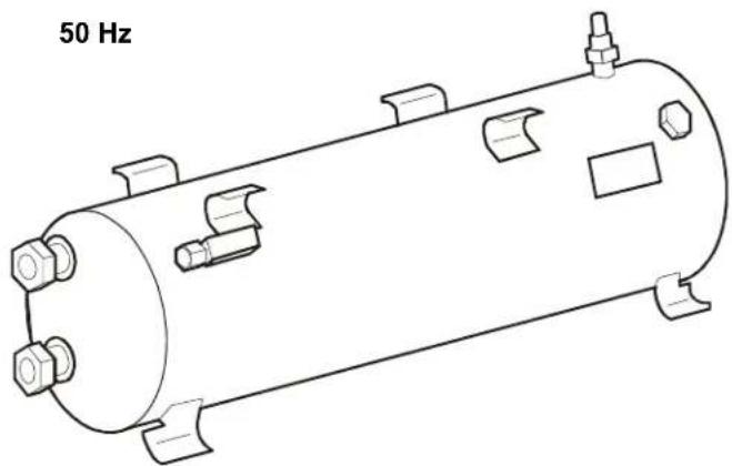
Technical line drawing of a cylindrical tank with mounting flanges and internal compartments (no text or symbols)| InRoom Cabinet Size 1 2 3 4 | 5 | ||||
| 50 Hz Air-Cooled Condenser Model | ACCD76002 | ACCD76003 | ACCD76002 (2) | ACCD76003 (2) | ACCD76011 (2) |
| 50 Hz Receiver Model (Qty) | ACAC76101 | ACAC76102 | ACAC76103 (2) | ACAC76104 (2) | ACAC76105 (2) |
| Max Refrigerant Charge 90% at 20°C (68°F)R-407C kg (lb) * | 24.0 (53) | 24.0 (53) | 24.0 (53) each | 24.0 (53) each | 24.0 (53) each |
| Connection inlet - mm (in) | 22 (7/8) | 22 (7/8) | 22 (7/8) | 22 (7/8) | 22 (7/8) |
| Connection thread/flange | 1 1/4 in(12 UNF) | 1 1/4 in(12 UNF) | 1 1/4 in(12 UNF) | 1 1/4 in(12 UNF) | 1 1/4 in(12 UNF) |
| Connection outlet - mm (in) | 22 (7/8) | 22 (7/8) | 22 (7/8) | 22 (7/8) | 22 (7/8) |
| Gauge | 7/16 (20 UNF) | 7/16 (20 UNF) | 7/16 (20 UNF) | 7/16 (20 UNF) | 7/16 (20 UNF) |
| Pressure relief valve connection | 1 1/4 in(12 UNF) | 1 1/4 in(12 UNF) | 1 1/4 in(12 UNF) | 1 1/4 in(12 UNF) | 1 1/4 in(12 UNF) |
| Height - mm (in) | 287 (11.3) | 287 (11.3) | 287 (11.3) each | 287 (11.3) each | 287 (11.3) each |
| Depth - mm (in) | 276 (10.9) | 276 (10.9) | 276 (10.9) each | 276 (10.9) each | 276 (10.9) each |
| Width - mm (in) | 824 (32.4) | 824 (32.4) | 824 (32.4) each | 824 (32.4) each | 824 (32.4) each |
| Weight - kg (lb) | 23.6 (52) | 23.6 (52) | 23.6 (52) each | 23.6 (52) each | 23.6 (52)each |
Display Interface
The display interface is standard on each system. The display interface provides precision control for the demanding requirements of these environments:
- Data centers
- Control rooms
- Clean rooms
- Switch rooms
- UPS rooms
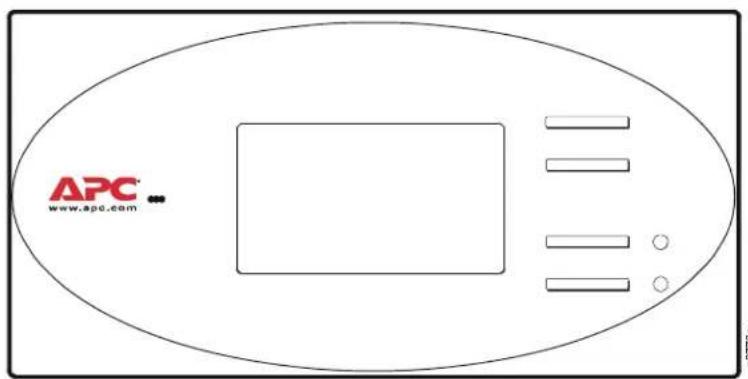
The easy-to-use display allows the operator to select options from the display interface to control and monitor the InRoom precision air conditioning system.
Logging
The display interface displays the most recent alarms. Each alarm log contains a time/date stamp as well as operating conditions at the time of occurrence. The display interface also displays run time, in hours, for major components (compressors, heaters, humidifier, fans).
Control Type
The display interface utilizes proportional and integral derivative (PID), a time-proven precision environmental control method. This allows for custom tuning of control variables to achieve the desired system response.
Functions
• Audible and Visual Alarms
- Sensor Status (Temperature, Humidity, and Pressure)
• Component State (On/Off, %)
- Component Runtimes
- Event Logging
- Configuration and Alarm Settings
- Password Protection
Open Architecture
The InRoom precision air conditioning system is open for integration with all building management systems. The display interface on the system supports Modbus RTU RS485.
Alarms
- Local Stop
- Compressor Low Pressure
- Compressor Failure
- E-heating Failure
- Humidifier Failure
• Humidifier 5 uS - Humidifier 20uS
- Fan Error
-
Filter Clocked
-
External Alarm
- Pump Failure
- Drycooler Failure
• Water Detector
• Room Temp Too High
• Room Humidity Too High
• Supply Temp Too High
• Supply Humidity Too High
• Room Temp Too Low
• Room Humidity Too Low
• Supply Temp Too Low
• Supply Humidity Too Low
• Water Temp To
• Water Temp To
- Fire/Smoke Detector
- Sensor Failure
- Sensor Broken
InRoom Model Sizes
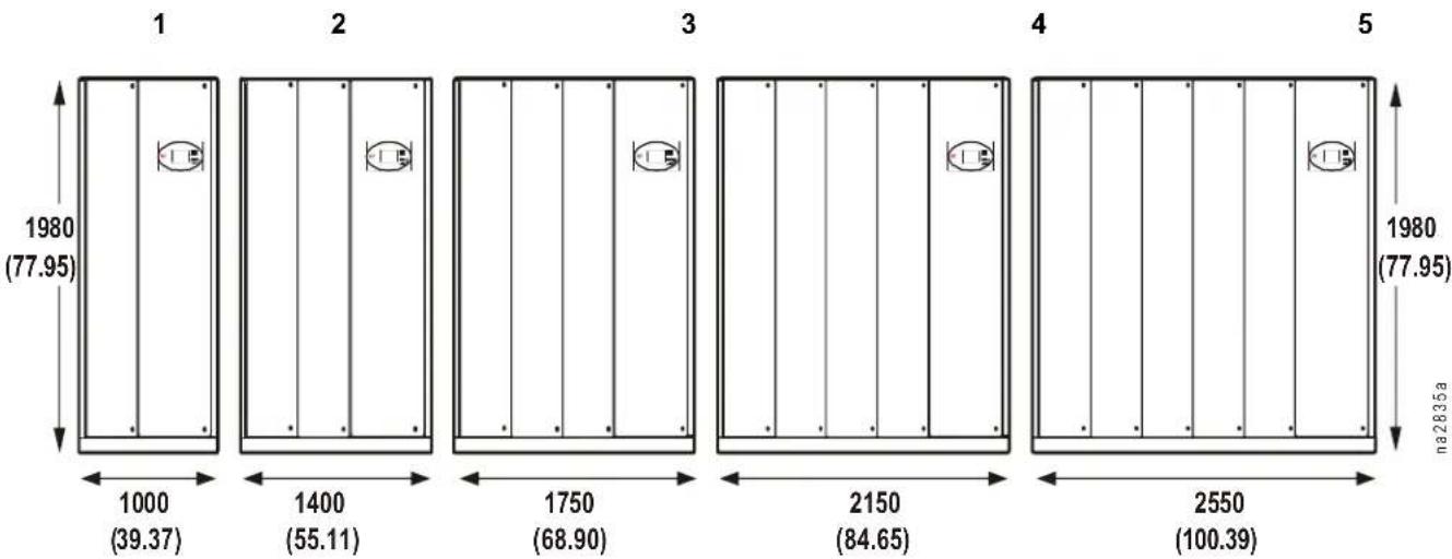
Different variations of the InRoom product range are defined by the airflow direction, the number of refrigerant circuits, and the type of cooling system. There are five cabinet sizes. The front service access for all cabinet sizes of the InRoom Precision Air Conditioner is 1 m (39 in).
The InRoom Fluid Cooled (Glycol) system with Economizer Coil differs from the other versions by having a larger cabinet size, not a larger capacity. There are no Fluid Cooled (Glycol) systems with Economizer Coils in Cabinet Size 1.
other
| Section | Height (mm) | Width (mm) | | ------- | ----------- | ---------- | | 1 | 1980 | 77.95 | | 2 | 1980 | 77.95 | | 3 | 1980 | 77.95 | | 4 | 1980 | 77.95 | | 5 | 1980 | 77.95 | | 1 | 1000 | 39.37 | | 2 | 1400 | 55.11 | | 3 | 1750 | 68.90 | | 4 | 2150 | 84.65 | | 5 | 2550 | 100.39 |*Dimensions are in mm (in).
Depth of all models is 890 mm (35 in).
| InRoom Direct Expansion Model Sizes | |||||
| C a | b | i | n | e | t |
| 1 refrigerant circuit | PA211PG211PACW211PGCW211 | PA311PG311PACW311PGCW311 | |||
| 2 refrigerant circuits | PA452PG452PACW452PGCW452 | PA612PG612PACW612PGCW612 | PA862PG862PACW862PGCW862 | ||
| InRoom Fluid Cooled (Glycol) with Economizer Model Sizes | |||||
| 1 refrigerant circuit PGE211 PGE311 | |||||
| 2 refrigerant circuits PGE452 PGE612 | |||||
| InRoom Chilled Water Model Sizes | |||||
| PCW400 PCW | 660 PCW900 PC | CW1100 PCW1500 | |||
InRoom Cooling Unit Configurations
Fluid Cooled (Glycol)
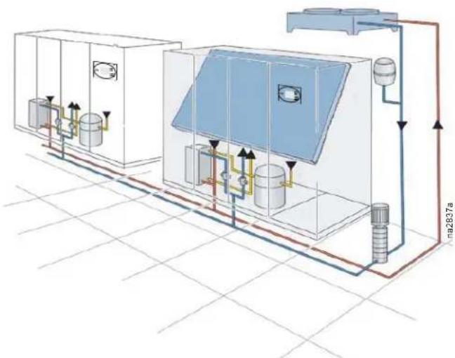
InRoom Fluid Cooled (Glycol) systems are completely charged and factory tested in a sealed system for reliability. In mid to low ambient climates, an economizer coil can be used to increase efficiency and extend compressor life. Economizer operation greatly reduces the energy consumption of the system. Water regulating valves control head pressure.
• System is used with a fluid cooler.
• Factory-tested as a sealed system.
- Eliminates the need for field refrigerant piping.
• No requirement for water treatment.
- Economizer option provides high efficiency.
- Low maintenance.
Fluid Cooled (Glycol) System
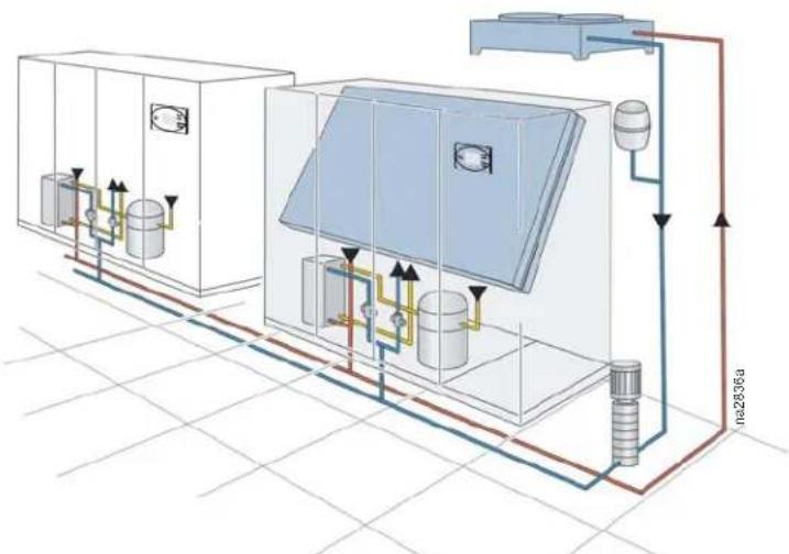
The InRoom Fluid Cooled (Glycol) System with Economizer is configured with both the glycol factory sealed system and an Economizer coil. During cold ambient conditions, the compressorized system will shut down and utilize the cold outdoor air to cool the glycol system, rerouting it from the heat exchanger to the Economizer coil for efficient operation.
natural_image
Technical diagram of a water treatment or gas processing system with tanks, valves, and piping (no text labels)Fluid Cooled (Glycol) System with Economizer
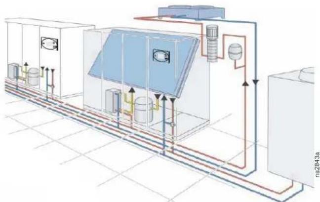
The InRoom Fluid Cooled (Glycol) System with Chilled Water System is a combination of a factory sealed glycol system and a chilled water system and contains two separate cooling coils. The controller microprocessor manages the systems to allow the glycol system to operate as standby to the chilled water system or vice versa, giving the added security of back-up cooling to the computer room.
flowchart
graph TD
    A["Feed tank"] --> B["Control panel"]
    B --> C["Storage unit"]
    C --> D["Reactor unit"]
    D --> E["Outlet"]
    style A fill:#f9f,stroke:#333
    style B fill:#bbf,stroke:#333
    style C fill:#bfb,stroke:#333
    style D fill:#ffb,stroke:#333
    style E fill:#fff,stroke:#333
Fluid Cooled (Glycol) System with Chilled Water Cooling System
Chilled Water
InRoom Chilled Water systems are available in a packaged fan-coil design. Room air is recirculated through the cooling coil, which transfers the heat load directly into the chilled water ring main. Water flow rate is regulated by a 2- or 3-way valve controlled by the controller microprocessor. Cooling towers are used as a source of heat rejection and can be used to serve multiple indoor units. Towers utilizing outdoor air require water treatment.
- The system is used with a cooling tower or other source of water.
• Factory sealed and tested system. - The need for field refrigerant piping is eliminated.
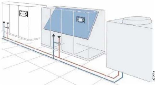
natural_image
Architectural diagram of a large industrial room with ventilation ducts and control panels (no text or symbols)Chilled Water Cooling System
Air Cooled (DX)
Air cooled systems are not pre-charged from the factory and require field refrigerant piping. Each installation requires an engineered piping solution. APC strongly recommends installation by a highly qualified refrigeration contractor to avoid improper elevation and long piping runs. The Air Cooled system uses refrigerant as the heat transfer medium. Room air recirculates through the InRoom unit which houses the evaporator coil, scroll compressor, and refrigeration system. A remotely mounted air-cooled condenser is connected to the unit. The sealed refrigeration circuit will absorb the room heat load and reject it to the outside atmosphere.
• System used with a remote air cooled condenser
• Field installed refrigerant piping is required
- Low maintenance
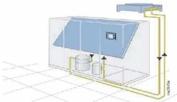
natural_image
3D schematic diagram of a water tank or storage unit with internal tanks and piping, no text or symbols presentAir Cooled System
The MultiCool System is a combination of the Air Cooled System and the Chilled Water System and contains two separate cooling coils. The controller microprocessor manages the MultiCool System to allow the air cooled by the Air Cooled system to operate as a standby system to the Chilled Water (CW) system or vice versa, giving the added security of back-up cooling to the computer room.
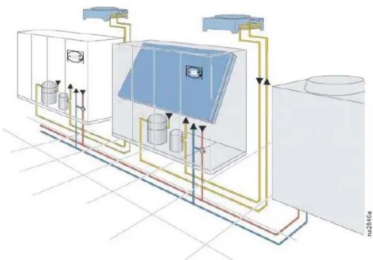
natural_image
Technical diagram of a dual-chamber HVAC system with heat exchangers and piping (no text or labels)MultiCool - Air Cooled System with Chilled Water Cooling System
60Hz Performance Specifications
Chilled Water (CW) - 60Hz
| Chilled Water PCW400 | Cabinet Size 1 | PCW660 Cabinet Size 2 | PCW900 Cabinet Size 3 | PCW1100 Cabinet Size 4 | PCW1500 Cabinet Size 5 |
| 26.7°C DB, 19.4°C WB (80°F DB, 67°F WB) 50% RH | |||||
| Total - kW (BTU/hr) | 53.6 (182,800) | 86.1 (293,800) | 120.1 (409,800) | 153.4 (553,400) | 197.8 (675,000) |
| Sensible - kW (BTU/hr) | 35.8 (128,999) | 58.4 (206,099) | 82.7 (288,999) | 102.4 (356,199) | 134.3 (465,099) |
| Flow Rate - L/m (GPM) 139.3 (36.8) | 229.4 (60.6) | 324.0 (85.6) | (108.4) 534.1 (14.0) | ||
| Total Pressure Drop Water Side - Kpa (ft) | 91.8 (30.7) | 129.2 (43.2) | 112.1 (37.5) | 124.7 (41.7) | 189.0 (63.2) |
| 23.9°C DB, 16.9°C WB (75°F DB, 62.5°F WB) 50% RH | |||||
| Total - kW (BTU/hr) | 29.4 (100,300) | 54.5 (186,000) | 65.5 (223,500) | 82.5 (281,500) | 104.8 (357,600) |
| Sensible - kW (BTU/hr) * | 25.5 (93,799) | 45.5 (162,099) | 59.1 (208,499) | 73.9 (258,999) | 95.3 (331,999) |
| Flow Rate - L/m (GPM) | 80.3 (21.2) | 147.6 (39.0) | 182.8 (48.3) | 227.1 (60.0) | 293.4 (77.5) |
| Total Pressure Drop Water Side - Kpa (ft) | 29.6 (9.9) | 62.8 (21.0) | 38.9 (13.0) | 43.4 (14.5) | 59.8 (20.0) |
| 23.9°C DB, 16.1°C WB (75°F DB, 61°F WB) 45% RH | |||||
| Total - kW (BTU/hr) | 29.9 (102,000) | 49.8 (169,900) | 66.3 (226,200) | 82.2 (280,500) | 105.8 (361,000) |
| Sensible - kW (BTU/hr) | 27.9 (101,999) | 47.8 (169,899) | 64.3 (226,199) | 80.2 (280,499) | 103.8 (360,999) |
| Flow Rate - L/m (GPM) | 81.4 (21.5) | 135.5 (35.8) | 185.1 (48.9) | 226.4 (59.8) | 296.0 (78.2) |
| Total Pressure Drop Water Side - Kpa (ft) | 31.4 (10.5) | 52.3 (17.5) | 39.5 (13.2) | 43.1 (14.54) | 60.4 (20.2) |
| 22.2°C DB, 15.5°C WB (72°F DB, 60°F WB) 50% RH | |||||
| Total - kW (BTU/hr) 25.0 (85,300) | 42.0 (143,300) | 54.8 (187,000) | 68.2 (232,700) | 6.3 (294,500) | |
| Sensible - kW (BTU/hr) | 23.0 (85,299) | 40.0 (143,299) | 52.8 (186,999) | 66.2 (232,699) | 84.3 (294,499) |
| Flow Rate - L/m (GPM) | 68.9 (18.2) | 115.1 (30.4) | 155.2 (41.0) | 190.0 (50.2) | 245.7 (64.9) |
| Total Pressure Drop Water Side - Kpa (ft) | 22.4 (7.5) | 39.8 (13.3) | 28.4 (9.5) | 31.1 (10.4) | 42.5 (14.2) |
| 22.2°C DB, 14.8°C WB (72°F DB, 58.6°F WB) 45% RH | |||||
| Total - kW (BTU/hr) 25.0 (85,300) | 42.0 (143,300) | 54.8 (187,000) | 68.2 (232,700) | 6.3 (294,500) | |
| Sensible - kW (BTU/hr | 23.0 (85,299) | 40.0 (143,299) | 52.8 (186,999) | 66.2 (232,699) | 84.3 (294,499) |
| Flow Rate - L/m (GPM) | 68.9 (18.2) | 115.1 (41.0) | 155.2 (41.0) | 190.0 (50.2) | 245.7 (64.9) |
| Total Pressure Drop Water Side - Kpa (ft) | 22.4 (7.5) | 39.8 (13.3) | 28.4 (9.5) | 31.1 (10.4) | 42.5 ( 14.2) |
| 21.1°C DB, 14.0°C WB(70°F DB, 58.5°F WB) 50% RH | |||||
| Total - kW (BTU/hr) 21.7 (74,000) | 36.6 (124,900) | 47.0 (160,400) | 58.5 (199,600) | 72.9 (248,700) | |
| Sensible - kW (BTU/hr) | 19.7 (73,999) | 34.6 (124,899) | 45.0 (160,399) | 56.5 (199,599) | 70.9 (248,699) |
| Flow Rate - L/m (GPM) | 60.6 (16.0) | 101.1 (26.7) | 135.1 (35.7) | 165.0 (43.6) | 210.8 (55.7) |
| Total Pressure Drop Water Side - Kpa (ft) | 16.7 (5.6) | 32.6 (10.9) | 23.0 (7.7) | 25.7 (8.6) | 31.7 (10.6) |
| 21.1°C DB, 14.0°C WB(70°F DB, 57.2°F WB) 45% RH | |||||
| Total - kW (BTU/hr) 21.7 (74,000) | 36.6 (124,900) | 47.0 (160,400) | 58.5 (199,600) | 72.9 (248,700) | |
| Sensible - kW (BTU/hr | 19.7 (73,999) | 34.6 (124,899) | 45.0 (160,399) | 56.5 (199,599) | 70.9 (248,699) |
| Flow Rate - L/m (GPM) | 60.6 (16.0) | 101.1 ( 26.7 ) | 135.1 (35.7) | 165.0 (43.6) | 210.8 (55.7) |
| Total Pressure Drop Water Side - Kpa (ft) | 16.7 (5.6) | 32.6 (10.9) | 23.0 (7.7) | 25.7 (8.6) | 31.7 (10 .6) |
| Valve Size - mm (in) | 32 (1 1/4) | 38.1 (1.5) | 50 (2.0) | 50 (2.0) | 50 (2.0) |
| Temperature medium in - °C (°F) | 7.2°C (45°F) | 7.2°C (45°F) | 7.2°C (45°F) | 7.2°C (45°F) | 7.2°C (45°F) |
| Temperature medium in - °C (°F) | 12.8°C (55°F) | 12.8°C (55°F) | 12.8°C (55°F) | 12.8°C (55°F) | 12.8°C (55°F) |
| Chilled Water Coil | |||||
| Face Area - m2(ft2) | 1.09 (11.77) | 1.66 (17.82) | 1.53 (16.52) | 1.94 (20.86) | 2.31 (24.88) |
| Rows Deep | 5 | 5 | 5 | 5 | 5 |
| Face Velocity - m/min (ft/min) | 130 (428) | 132 (432) | 112 (367) | 102 (336) | 114 (373) |
| * Nominal Rating Point | |||||
| Chilled Water Continued PCW400 | Cabinet Size 1 | PCW660 Cabinet Size 2 | PCW900 Cabinet Size 3 | PCW1100 Cabinet Size 4 | PCW1500 Cabinet Size 5 |
| Fan Information | |||||
| Number of Fans 1 1 2 2 3 | |||||
| Air Flow - M3/hr (CFM) 8495 (5,000) | 12997 (7,650) | 18995 (11,180) | 2002 (12,950) | 29495 (17,360) | |
| External Static Pressure - Pa (in WC) 50 (0.2) | 50 (0.2) | 50 (0.2) | 50 (0.2) | ||
| Sound Power Level - dBA 72.1 75.2 | 71.0 | 74.4 73.10 | |||
| Total Fan Power Consumption - kW (hp) | 1.7 (2.3) | 2.6 (3.5) | 5.3 (7.1) | 5.4 (7.2) | 8.8 (11.8) |
| Connection Sizes | |||||
| Upflow Chilled Water In/Out - mm (in) | 35 (1 3/8) | 42 (1 5/8) | 54 (2 1/8) | 70 (2 3/4) | 70 (2 3/4) |
| Downflow Chilled Water In/Out - mm (in) | 35 (1 3/8) | 42 (1 5/8) | 54 (2 1/8) | 54 (2 1/8) | 54 (2 1/8) |
| Humidifier Supply Line - mm (in) | 6 (1/4) | 6 (1/4) | 6 (1/4) | 6 (1/4) | 6 (1/4) |
| Condensate Drain Linc - mm OD (in ID) | 21 (3/4) | 21 (3/4) | 21 (3/4) | 21 (3/4) | 21 (3/4) |
| Humidification - Solid State Electrode, Canister | |||||
| Flush Cycle | Automatic | Automatic | Automatic | Automatic | Automatic |
| kg/hr (lb/hr) | 8.0 (17.6) | 8.0 (17.6) | 15.0 (33.1) | 15.0 (33.1) | 15.0 (33.1) |
| Electric Reheat - Equally Loaded Three (3) phase | |||||
| Capacity - kW (BTU/hr) - Includes Motor Heat | |||||
| 460 V | 12.0 (40982.4) | 18 (61473.6) | 18 (61473.6) | 27 (92210.4) | 27 (92210.4) |
| 230 V | 9.0 (30736.8) | 18 (61473.6) | 18 (61473.6) | 27 (92210.4) | 27 (92210.4) |
| Number of Stages | 1 2 2 3 3 | ||||
| Downflow Filters - mm | Quantities | ||||
| 836 x 546 x 92 G4 | N/A | N/A | 3 3 3 | ||
| 836 x 393 x 92 G4 | N/A | 1 N/A 1 2 | |||
| 836 x 446 x 92 G4 | 2 2 N/A N/A N/A | ||||
| Upflow Filters - mm | Quantities | ||||
| 795 x 508 x 92 G4 | N/A | N/A | 1 2 2 | ||
| 795 x 341 x 92 G4 | 1 1 N/A 1 1 | ||||
| 795 x 333 x 92 G4 | N/A | 1 N/A N/A 1 | |||
| 795 x 365 x 92 G4 | N/A | N/A | 1 1 1 | ||
| 795 x 516 x 92 G4 | N/A | N/A | 1 N/A N/A | ||
| 795 x 502 x 92 G4 | 1 1 N/A N/A N/A | ||||
| Physical Data | |||||
| Weight - kg (lb) | 307 (677) | 362 (798) | 547 (1206) | 568 (1252) | 755 (1664) |
| Height - mm (in) | 1980 (77.95) | 1980 (77.95) | 1980 (77.95) | 1980 (77.95) | 1980 (77.95) |
| Width - mm (in) 1000 (39.37) | 1400 (55.12) 1750 | (68.90) 2150 | (84.65) 2550 (100.39) | ||
| Depth - mm (in) | 890 (35) | 890 (35) | 890.0 (35) | 890.0 (35) | 890 (35) |
Air Cooled (DX) System – 60Hz
| Air Cooled PA211 | Cabinet Size 1 | PA311 Cabinet Size 2 | PA452 Cabinet Size 3 | PA612 Cabinet Size 4 | PA862 Cabinet Size 5 |
| 26.7°C DB, 19.4°C WB (80°F DB, 67°F WB) 50% RH | |||||
| Total - kW (BTU/hr) 19.8 (67,450) | 29.9 (102,000) | 44.2 (151,000) | 55.2 (188,290) | 4.9 (290,000) | |
| Sensible - kW (BTU/hr) | 19.8 (67,450) | 29.9 (102,000) | 41.3 (141,000) | 55.2 (188,290) | 75.4 (257,000) |
| 23.9°C DB, 16.9°C WB (75°F DB, 62.5°F WB) 50% RH | |||||
| Total - kW (BTU/hr) | 18.1 (61,940) | 27.6 (94,000) | 40.5 (138,000) | 50.8 (173,470) | 78.8 (269,000) |
| Sensible - kW (BTU/hr) * | 18.1 (61,940) | 27.6 (94,000) | 40.5 (138,000) | 50.8 (173,470) | 72.8 (249,000) |
| 23.9°C DB, 16.1°C WB (75°F DB, 61°F WB) 45% RH | |||||
| Total - kW (BTU/hr) 18.1 (61,940) | 27.6 (94,000) | 40.5 (138,000) | 50.8 (173,470) | 72.2 (264,000) | |
| Sensible - kW (BTU/hr) | 18.1 (61,940) | 27.6 (94,000) | 40.5 (138,000) | 50.8 (173,470) | 77.2 (264,000) |
| 22.2°C DB, 15.5°C WB (72°F DB, 60°F WB) 50% RH | |||||
| Total - kW (BTU/hr) 17.1 (58,330) | 26.4 (90,000) | 38.7 (132,000) | 48.2 (164,635) | 75.1 (256,000) | |
| Sensible - kW (BTU/hr) | 17.1 (58,330) | 26.4 (90,000) | 38.7 (132,000) | 48.2 (164,635) | 71.0 (242,000) |
| 22.2°C DB, 14.8°C WB (72°F DB, 58.6°F WB) 45% RH | |||||
| Total - kW (BTU/hr) 17.1 (58,330) | 26.4 (90,000) | 38.6 (132,000) | 48.2 (164,635) | 75.1 (256,000) | |
| Sensible - kW (BTU/hr) | 17.1 (58,330) | 26.4 (90,000) | 38.6 (132,000) | 48.2 (164,635) | 71.0 (242,000) |
| 21.1°C DB, 14.0°C WB (70°F DB, 58.5°F WB) 50% RH | |||||
| Total - kW (BTU/hr) 16.7 (57,095) | 25.6 (87,000) | 37.4 (128,000) | 47.1 (160,740) | 74.4 (253,840) | |
| Sensible - kW (BTU/hr) | 16.7 (57,095) | 25.6 (87,000) | 37.4 (128,000) | 47.1 (160,740) | 74.4 (253,840) |
| 21.1°C DB, 14.0°C WB (70°F DB, 57.2°F WB) 45% RH | |||||
| Total - kW (BTU/hr) 16.7 (57,095) | 25.6 (87,000) | 37.4 (128,000) | 47.1 (160,740) | 74.4 (253,840) | |
| Sensible - kW (BTU/hr) (16.7 (57,095) | 25.6 (87,000) | 37.4 (128,000) | 37.4 (128,000) | 47.1 (160,740) | 74.4 (253,840) |
| Condensing temperature for all above conditions: 52°C (125°F) | |||||
| Refrigerant type for all models: R-407C | |||||
| Refrigerant Charge per Circuit - kg (lbs) | 2.8 (6.17) | 3.9 (8.6) | 4.4 (9.7) | 3.9 (8.6) | 4.6 (10.1) |
| Compressor Information - COP** (ARI*** Conditions): 7.2°C (45°F) Evaporating, 54°C (130°F) Condensing | |||||
| Number of compressors | 1 | 1 | 2 | 2 | 2 |
| COP | 3.0 | 3.0 | 3.0 | 3.0 | 3.1 |
| Evaporator Coil | |||||
| Face Area - m2 (ft2) | 0.77 (8.32) | 1.17 (12.63) | 1.46 (15.72) | 1.86 (20.02) | 2.22 (23.90) |
| Rows Deep | 4 | 4 | 4 | 4 | 5 |
| Face Velocity - m/min (ft/min) | 125 (410) | 104 (342) | 117 (383) | 130 (428) | 141 (461) |
| * Nominal Rating Point** Coefficient of Performance*** Air Conditioning and Refrigeration Institute | |||||
| Air Cooled (DX) Continued PA211 | Cabinet Size 1 | PA311 Cabinet Size 2 | PA452 Cabinet Size 3 | PA612 Cabinet Size 4 | PA862 Cabinet Size 5 |
| Fan Information | |||||
| Number of Fans 1 1 2 2 3 | |||||
| Air Flow - M^3/hr (CFM) 7493 (4,410) | 10007 (5,890) | 14000 (8,240) 201 | 16 (11,890) 240 | 07 (14,130) | |
| External Static Pressure - Pa (in WC) | 50 (0.2) | 50 (0.2) | 50 (0.2) | 50 (0.2) | 50 (0.2) |
| Sound Power Level - dBA | 75.40 | 79.30 | 77.40 | 83.20 | 81.50 |
| Total Fan Power Consumption - kW (hp) | 1.7 (2.3) | 2.1 (2.8) | 3.1 (4.2) | 6.1 (8.2) | 6.2 (8.3) |
| Connection Sizes | |||||
| Number of DX Circuits | 1 1 2 2 2 | ||||
| Liquid Line O.D. - mm (in) | 12 (1/2) | 16 (5/8) | 16 (5/8) | 16 (5/8) | 16 (5/8) |
| Discharge Line O.D. - mm (in) | 16 (5/8) | 22 (7/8) | 22 (7/8) | 22 (5/8) | 22 (5/8) |
| Humidifier Supply Line - mm (in) | 6 (1/4) | 6 (1/4) | 6 (1/4) | 6 (1/4) | 6 (1/4) |
| Condensate Drain Line - mm OD (in ID) | 21 (3/4) | 21 (3/4) | 21 (3/4) | 21 (3/4) | 21 (3/4) |
| Humidification - Solid State Electrode, Canister | |||||
| Flush Cycle | Automatic | Automatic | Automatic | Automatic | Automatic |
| kg/hr (lb/hr) | 8.0 (17.6) | 8.0 (17.6) | 15.0 (33.1) | 15.0 (33.1) | 15.0 (33.1) |
| Electric Reheat - Equally Loaded Three (3) phase | |||||
| Capacity - kW (BTU/hr) - Includes Motor Heat | |||||
| 460 V | 12.0 (40982.4) | 18 (61473.6) | 18 (61473.6) | 27 (92210.4) | 27 (92210.4) |
| 230 V | 9.0 (30736.8) | 18 (61473.6) | 18 (61473.6) | 27 (92210.4) | 27 (92210.4) |
| Number of Stages | 2 3 3 3 3 | ||||
| Downflow Filters - mm | Quantities | ||||
| 1050 x 453 x 47 G4 2 2 1 1 1 | |||||
| 1050 x 398 x 47 G4 N/A | 1 3 4 5 | ||||
| Upflow Filters - mm | Quantities | ||||
| 700 x 340 x 47 G4 | 1 1 N/A | 1 1 | |||
| 700 x 332 x 47 G4 | N/A | 1 | N/A | N/A | 1 |
| 700 x 502 x 47 G4 | 1 1 1 1 1 | ||||
| 700 x 508 x 47 G4 | N/A | N/A | 1 2 2 | ||
| 700 x 508 x 47 G4 | N/A | N/A | 1 | N/A | N/A |
| Physical Data | |||||
| Weight - kg (lb) | 353 (778) | 453 (999) | 556 (1226) | 680 (1499) | 807 (1779) |
| Height - mm (in) | 1980 (77.95) | 1980 (77.95) | 1980 (77.95) | 1980 (77.95) | 1980 (77.95) |
| Width - mm (in) | 1000 (39.37) | 1400 (55.11) | 1750 (68.90) | 2150 (84.65) | 2550 (100.39) |
| Depth - mm (in) | 890 (35) | 890 (35) | 890 (35) | 890 (35) | 890 (35) |
MultiCool – Air Cooled (DX) with CW – 60Hz
Operational Mode: Air Cooled (DX)
| Net Cooling Capacity PACW211 | Cabinet Size 1 | PACW311 Cabinet Size 2 | PACW452 Cabinet Size 3 | PACW612 Cabinet Size 4 | PACW862 Cabinet Size 5 |
| 26.7°C DB, 19.4°C WB (80°F DB, 67°F WB) 50% RH | |||||
| Total - kW (BTU/hr) | 19.2 (65,455) | 29.7 (101,460) | 43.7 (149,150) | 54.5 (186,105) | 83.9 (286,235) |
| Sensible - kW (BTU/hr) | 19.2 (65,455) | 29.7 (101,460) | 40.8 (139,365) | 54.5 (186,105) | 74.4 (253,840) |
| 23.9°C DB, 16.9°C WB (75°F DB, 62.5°F WB) 50% RH | |||||
| Total - kW (BTU/hr) | 17.8 (60,895) | 27.6 (94,050) | 40.0 (136,515) | 50.3 (171,760) | 77.8 (265,525) |
| Sensible - kW (BTU/hr) * | 17.8 (60,895) | 27.6 (94,050) | 40.0 (136,515) | 50.3 (171,760) | 71.8 (245,100) |
| 23.9°C DB, 16.1°C WB (75°F DB, 61°F WB) 45% RH | |||||
| Total - kW (BTU/hr) | 17.8 (60,895) | 27.6 (94,050) | 40.0 (136,515) | 50.3 (171,760) | 76.2 (260,015) |
| Sensible - kW (BTU/hr) | 17.8 (61,895) | 27.6 (94,050) | 40.0 (136,515) | 50.2 (171,475) | 76.2 (260,015) |
| 22.2°C DB, 15.5°C WB (72°F DB, 60°F WB) 50% RH | |||||
| Total - kW (BTU/hr) | 16.8 (57,380) | 26.3 (89,775) | 38.2 (130,340) | 47.8 (163,020) | 74.1 (252,890) |
| Sensible - kW (BTU/hr) | 16.8 (57,380) | 26.3 (89,775) | 38.2 (130,340) | 47.8 (163,020) | 70.0 (238,825) |
| 22.2°C DB, 14.8°C WB (72°F DB, 58.6°F WB) 45% RH | |||||
| Total - kW (BTU/hr) | 16.8 (57,380) | 26.3 (89,775) | 38.2 (130,340) | 47.7 (163,020) | 73.3 (250,230) |
| Sensible - kW (BTU/hr) | 16.8 (57,380) | 26.3 (89,775) | 38.2 (130,340) | 47.7 (163,020) | 73.3 (250,230) |
| 21.1°C DB, 14.0°C WB (70°F DB, 58.5°F WB) 50% RH | |||||
| Total - kW (BTU/hr) | 16.4 (56,050) | 25.6 (87,485) | 36.9 (126,065) | 46.1 (157,225) | 71.1 (242,820) |
| Sensible - kW (BTU/hr) | 16.4 (56,050) | 25.6 (87,485) | 36.9 (126,065) | 46.1 (157,225) | 71.1 (242,820) |
| 21.1°C DB, 14.0°C WB (70°F DB, 57.2°F WB) 45% RH | |||||
| Total - kW (BTU/hr) | 16.4 (56,050) | 25.6 (87,485) | 36.9 (126,065) | 46.1 (157,225) | 71.1 (242,820) |
| Sensible - kW (BTU/hr) | 16.4( 56,050) | 25.6 (87,485) | 36.9 (126,065) | 46.1 (157,225) | 71.1 (242,820) |
| Condensing temperature for all above conditions: 52^ C( 125^ F) | |||||
| Refrigerant type for all models: R-407C | |||||
| Refrigerant Charge per Circuit - kg (lbs) | 2.8 (6.17) | 3.9 (8.6) | 4.4 (9.7) | 3.9 (8.6) | 4.6 (10.1) |
| Compressor Information – COP** (ARI*** Conditions): 7.2°C (45°F) Evaporating, 54°C (130°F) Condensing | |||||
| N u m | b | c | r | o | f |
| COP | 3.0 | 3.0 | 3.0 | 3.0 | 3.1 |
| Connection Sizes | |||||
| Liquid Line OD - mm (in) | 12 (1/2) | 16 (5/8) | 16 (5/8) | 16 (5/8) | 16 (5/8) |
| Discharge Line OD - mm (in) | 16 (5/8) | 22 (7/8) | 22 (7/8) | 22 (7/8) | 22 (7/8) |
| Evaporator Coil | |||||
| Face Area - m^2( ft^2) | 0.77 (8.32) | 1.17 (12.63) | 1.46 (15.72) | 1.86 (20.02) | 2.22 (23.90) |
| R o | w | s | D | e | e |
| Face Velocity - m/min (ft/min) | 125 (410) | 104 (342) | 117 (383) | 124 (407) | 141 (461) |
| * Nominal Rating Point ** Coefficient of Performance *** Air Conditioning and Refrigeration Institute | |||||
Operational Mode: Chilled Water (CW)
| Net Cooling Capacity - 7.2°C (45°F) EWT | PACW211Cabinet Size 1 | PACW311Cabinet Size 2 | PACW452Cabinet Size 3 | PACW612Cabinet Size 4 | PACW862Cabinet Size 5 |
| 26.7°C DB, 19.4°C WB (80°F DB, 67°F WB) 50% RH | |||||
| Total - kW (BTU/hr) | 34.3 (117,040) | 48.6 (165,965) | 63.4 (216,505) | 83.9 (286,520) | 104.3 (355,965) |
| Sensible - kW (BTU/hr) | 25.9 (88,540) | 36.6 (124,830) | 47.9 (163,400) | 63.3 (215,935) | 78.5 (268,090) |
| Flow Rate - L/m (GPM) | 98.4 (26.0) | 138.2 (36.5) | 182.1 (48.1) | 244.5 (64.6) | 302.5 (79.9) |
| Total Pressure Drop Water Side - Kpa (ft) | 88.8 (29.7) | 58.0 (19.4) | 79.5 (26.6) | 76.5 (25.6) | 58.6 (19.6) |
| 23.9°C DB, 16.9°C WB (75°F DB, 62.5°F WB) 50% RH | |||||
| Total - kW (BTU/hr) | 20.0 (68,115) | 27.7 (94,620) | 36.9 (125,780) | 48.1 (164,065) | 60.2 (205,485) |
| Sensible - kW (BTU/hr) * | 20.0 (68,115) | 27.7 (94,620) | 36.9 (125,780) | 48.1 (164,065) | 57.6 (196,460) |
| Flow Rate - L/m (GPM) | 59.4 (15.7) | 81.4 (21.5) | 109.4 (28.9) | 146.9 (38.8) | 182.8 (48.3) |
| Total Pressure Drop Water Side Kpa (ft) | 32.0 (10.7) | 19.1 (6.4) | 28.1 (9.4) | 27.2 (9.1) | 20.3 (6.8) |
| 23.9°C DB, 16.1°C WB (75°F DB, 61°F WB) 45% RH | |||||
| Total - kW (BTU/hr) | 20.0 (68,115) | 27.7 (94,620) | 36.9 (125,780) | 48.1 (164,065) | 61.7 (210,425) |
| Sensible - kW (BTU/hr) | 20.0 (68,115) | 27.7 (94,620) | 36.9 (125,780) | 48.1 (164,065) | 61.7 (210,425) |
| Flow Rate - L/m (GPM) 59.4 (15.7) | 81.4 (21.5) 109.4 (28.9) 146.9 (38.8) 186.6 (49.3) | ||||
| Total Pressure Drop Water Side - Kpa (ft) | 32.0 (10.7) | 19.1 (6.4) | 28.1 (9.4) | 27.2 (9.1) | 21.8 (7.3) |
| 22.2°C DB, 15.5°C WB (72°F DB, 60°F WB) 50% RH | |||||
| Total - kW (BTU/hr) | 16.1 (55,100) | 22.4 (76,475) | 29.3 (100,130) | 37.4 (127,680) | 48.6 (165,965) |
| Sensible - kW (BTU/hr) | 16.1 (55,100) | 22.4 (76,475) | 29.3 (100,130) | 37.4 (127,680) | 48.5 (165,680) |
| Flow Rate - L/m (GPM) | 49.2 (13.0) | 67.0 (17.7) | 89.3 (23.6) | 118.1 (31.1) | 151.0 (39.9) |
| Total Pressure Drop Water Side - Kpa (ft) | 21.8 (7.3) | 13.2 (4.4) | 19.4 (6.5) | 18.5 (6.2) | 14.4 (4.7) |
| 22.2°C DB, 14.8°C WB (72°F DB, 58.6°F WB) 45% RH | |||||
| Total - kW (BTU/hr) | 14.7 (50,255) | 22.4 (76,475) | 29.3 (100,130) | 37.4 (127,680) | 48.5 (165,680) |
| Sensible - kW (BTU/hr) | 14.7 (50,255) | 22.4 (76,475) | 29.3 (100,130) | 37.4 (127,680) | 48.5 (165,680) |
| Flow Rate - L/m (GPM) | 49.2 (13.0) | 67.0 (17.7) | 89.3 (23.5) | 118.1 (31.1) | 151.0 (39.9) |
| Total Pressure Drop Water Side - Kpa (ft) | 21.8 (7.3) | 13.2 (4.4) | 19.4 (6.5) | 18.5 (6.2) | 14.4 (4.7) |
| 21.1°C DB, 14.0°C WB (70°F DB, 58.5°F WB) 50% RH | |||||
| Total - kW (BTU/hr) | 13.7 (46,645) | 18.9 (64,505) | 24.2 (82,650) | 29.9 (102,125) | 39.1 (133,570) |
| Sensible - kW (BTU/hr) | 13.7 (46,645) | 18.9 (64,505) | 24.2 (82,650) | 29.9 (102,125) | 39.1 (133,570) |
| Flow Rate - L/m (GPM) | 42.4 (11.2) | 57.2 (15.1) | 75.3 (19.9) | 97.7 (25.8) | 125.3 (33.1) |
| Total Pressure Drop Water Side - Kpa (ft) | 16.1 (5.4) | 9.6 (3.2) | 14.1 (4.7) | 12.3 (4.1) | 10.5 (3.5) |
| 21.1°C DB, 14.0°C WB (70°F DB, 57.2°F WB) 45% RH | |||||
| Total - kW (BTU/hr) | 13.7 (46,645) | 18.9 (64,505) | 24.2 (82,650) | 29.9 (102,125) | 39.1 (133,570) |
| Sensible - kW (BTU/hr) | 18.9 (64,505) | 24.2 (82,650) | 29.9 (102,125) | 39.1 (133,570) | |
| Flow Rate - L/m (GPM) | 42.4 (11.2) | 57.2 (15.1) | 75.3 (19.9) | 97.7 (25.8) | 125.3 (33.1) |
| Total Pressure Drop Water Side - Kpa (ft) | 16.1 (5.4) | 9.6 (3.3) | 14.1 (4.7) | 12.3 (4.1) | 10.5 (3.5) |
| Valve Size - mm (in) | 25 (1.0) | 32 (1.25) | 32 (1.25) | 40 (1.5) | 50 (2.0) |
| Temperature medium in - °C (°F) | 7.2°C (45°F) | 7.2°C (45°F) | 7.2°C (45°F) | 7.2°C (45°F) | 7.2°C (45°F) |
| Temperature medium in - °C (°F) | 12.8°C (55°F) | 12.8°C (55°F) | 12.8°C (55°F) | 12.8°C (55°F) | 12.8°C (55°F) |
| Chilled Water Coil | |||||
| Face Area - m2 (ft2) | 0.77 (8.32) | 1.17 (12.63) | 1.46 (15.72) | 1.86 (20.02) | 2.22 (23.90) |
| Rows Deep | 4 | 4 | 4 | 4 | 5 |
| Face Velocity - m/min (ft/min) | 161 (529) | 142 (466) | 160 (524) | 173 (569) | 179 (588) |
| Connection Sizes | |||||
| Chilled Water In/Out. - mm (in) | 35 (1 3/8) | 35 (1 3/8) | 42 (1 5/8) | 54 (2 1/8) | 54 (2 1/8) |
| * Nominal Rating Point | |||||
| Information common to both modes PACW211 | PACW311Cabinet Size 1 | PACW452Cabinet Size 2 | PACW612Cabinet Size 3 | PACW862Cabinet Size 4 | |
| Connection Sizes | |||||
| Humidifier Supply Line - mm (in) 6 (1/4) | 6 (1/4) 6 (1/4) 6 | (1/4) 6 (1/4) | |||
| Condensate Drain Line - mm OD (in ID) 21 | (3/4) 21 (3/4) 21 | (3/4) 21 (3/4) 21 | (3/4) | ||
| Fan Information | |||||
| N u | m | b | c | r | o |
| Air Flow M3/hr (CFM) 7034 (4,140) | 10007 (5,890) | 14000 (8,240) 193 | 86 (11,410) 2400 | 7 (14,130) | |
| External Static Pressure - Pa (in WC) 50 (0.2) | 50 (0.2) 50 (0.2) 50 (0.2) | 50 (0.2) 50 (0.2) | 2) | ||
| Sound Power Level - dBA | 76.6 | 79.7 | 78.6 | 83.4 | |
| Total Fan Power Consumption - kW (hp) | 2.0 (2.7) | 2.3 (3.1) | 3.6 (4.8) | 6.3 (8.4) | |
| Humidification - Solid State Electrode, Canister | |||||
| Flush Cycle | Automatic | Automatic | Automatic | Automatic | Automatic |
| kg/hr (lb/hr) | 8.0 (17.6) | 8.0 (17.6) | 15.0 (33.1) | 15.0 (33.1) | 15.0 (33.1) |
| Electric Reheat – Equally Loaded Three (3) phase | |||||
| Capacity - kW (BTU/hr) - Includes Motor Heat | |||||
| 460 V | 12.0 (40982.4) | 18 (61473.6) | 18 (61473.6) | 27 (92210.4) | 27 (92210.4) |
| 230 V | 9.0 (30736.8) 18 | (61473.6) 18 (61473.6) | 473.6) 27 (92210.4) | 4) 27 (92210.4) | |
| N u | m | b | e | r | o |
| Downflow Filters - mm | Quantities | ||||
| 1050 x 453 x 47 G4 | 2 | 2 | 1 | 1 | 1 |
| 1050 x 398 x 47 G4 | N/A | 1 | 3 | 4 | 5 |
| Upflow Filters - mm | Quantities | ||||
| 700 x 340 x 47 G4 | 1 | 1 | N/A | 1 | 1 |
| 700 x 332 x 47 G4 | N/A | 1 | N/A | N/A | 1 |
| 700 x 502 x 47 G4 | 1 | 1 | 1 | 1 | 1 |
| 700 x 508 x 47 G4 | N/A | N/A | 1 | 2 | 2 |
| 700 x 508 x 47 G4 | N/A | N/A | 1 | N/A | N/A |
| Physical Data | |||||
| Weight - kg (lb) | 372 (820) | 480 (1056) | 600 (1322) | 740 (1631) | 884 (1949) |
| Height - mm (in) | 1980 (77.95) 1980 (77.95) 1980 (77.95) 1980 (77.95) | ||||
| Width - mm (in) | 1000 (39.37) | 1400 (55.11) | 1750 (68.90) | 2150 (84.65) | 2550 (100.39) |
| Depth - mm (in) | 890 (35) | 890 (35) | 890 (35) | 890 (35) | 890 (35) |
Fluid Cooled (Glycol 40%) – 60Hz
| Net Cooling Capacity PG211 | Cabinet Size 1 | PG311 Cabinet Size 2 | PG452 Cabinet Size 3 | PG612 Cabinet Size 4 | PG862 Cabinet Size 5 |
| 26.7°C DB, 19.4°C WB (80°F DB, 67°F WB) 50% RH | |||||
| Total - kW (BTU/hr) | 19.8 (67,450) | 30.0 (102,410) | 44.2 (150,785) | 55.2 (188,290) | 84.9 (289,750) |
| Sensible - kW (BTU/hr) | 19.8 (67,450) | 30.0 (102,410) | 41.3 (140,980) | 55.2 (188,290) | 75.4 (257,355) |
| 23.9°C DB, 16.9°C WB (75°F DB, 62.5°F WB) 50% RH | |||||
| Total - kW (BTU/hr) | 18.1 (61,940) | 27.8 (95,000) | 40.5 (138,130) | 50.8 (173,470) | 78.8 (269,040) |
| Sensible - kW (BTU/hr) * | 18.1 (61,940) | 27.8 (95,000) | 40.5 (138,130) | 50.8 (173,470) | 72.8 (248,615) |
| 23.9°C DB, 16.1°C WB (75°F DB, 61°F WB) 45% RH | |||||
| Total - kW (BTU/hr) | 18.1 (61,940) | 27.8 (95,000) | 40.5 (138,130) | 50.8 (173,470) | 77.2 (263,530) |
| Sensible - kW (BTU/hr) | 18.1 (61,940) | 27.8 (95,000) | 40.5 (138,130) | 50.8 (173,470) | 77.2 (263,530) |
| 22.2°C DB, 15.5°C WB (72°F DB, 60°F WB) 50% RH | |||||
| Total - kW (BTU/hr) | 17.1 (58,330) | 26.6 (90,725) | 38.7 (131,955) | 48.2 (164,635) | 75.1 (256,405) |
| Sensible - kW (BTU/hr) | 17.1 (58,330) | 26.6 (90,725) | 38.7 (131,955) | 48.2 (164,635) | 71.0 (242,440) |
| 22.2°C DB, 14.8°C WB (72°F DB, 58.6°F WB) 45% RH | |||||
| Total - kW (BTU/hr) | 17.1 (58,330) | 26.4 (90,725) | 38.7 (131,955) | 48.2 (164,635) | 74.4 (253,840) |
| Sensible - kW (BTU/hr) | 17.1 (58,330) | 26.4 (90,725) | 38.7 (131,955) | 48.2 (164,635) | 74.4 (253,840) |
| 21.1°C DB, 14.0°C WB (70°F DB, 58.5°F WB) 50% RH | |||||
| Total - kW (BTU/hr) | 16.7 (57,095) | 25.9 (88,540) | 37.4 (127,680) | 47.1 (160,740) | 72.2 (246,335) |
| Sensible - kW (BTU/hr) | 16.7 (57,095) | 25.9 (88,540) | 37.4 (127,680) | 47.1 (160,740) | 72.2 (246,335) |
| 21.1°C DB, 14.0°C WB (70°F DB, 57.2°F WB) 45% RH | |||||
| Total - kW (BTU/hr) | 16.7 (57,095) | 25.9 (88,540) | 37.4 (127,680) | 47.4 (161,785) | 72.2 (246,335) |
| Sensible - kW (BTU/hr) | 16.7 (57,095) | 25.9 (88,540) | 37.4 (127,680) | 47.1 (160,740) | 72.2 (246,335) |
| Condensing temperature for all above conditions: 52°C (125°F) | |||||
| Refrigerant type for all models: R-407C | |||||
| Refrigerant Charge per Circuit - kg (lbs) | 2.8 (6.17) | 3.9 (8.6) | 4.4 (9.7) | 3.9 (8.6) | 4.6 (10.1) |
| Compressor Information - COP** (ARI*** Conditions): 7.2°C (45°F) Evaporating, 54°C (130°F) Condensing | |||||
| N u m | b | c | r | o | f |
| COP | 3.0 | 3.0 | 3.0 | 3.0 | 3.1 |
| Evaporator Coil | |||||
| Face Area - m^2 ( ft^2 ) | 0.77 (8.32) | 1.17 (12.63) | 1.46 (15.72) | 1.86 (20.02) | 2.22 (23.90) |
| R o | w | s | D | e | e |
| Face Velocity - m/min (ft/min) | 125 (410) | 104 (342) | 117 (383) | 130 (428) | 141 (461) |
| * Nominal Rating Point** Coefficient of Performance*** Air Conditioning and Refrigeration Institute | |||||
| Fluid Cooled (Glycol 40%) Continued PG211 | Cabinet Size 1 | PG311 Cabinet Size 2 | PG452 Cabinet Size 3 | PG612 Cabinet Size 4 | PG862 Cabinet Size 5 |
| Fan Information | |||||
| Number of Fans 1 1 2 2 3 | |||||
| Air Flow - M3/hr (CFM) 7493 (4,410) | 10007 (5,890) | 14000 (8,240) | 20116 (11,890) | 24007 (14,130) | |
| External Static Pressure - Pa (in WC) | 50 (0.2) | 50 (0.2) | 50 (0.2) | 50 (0.2) | 50 (0.2) |
| Sound Power Level - dBA | 75.4 | 79.2 | 77.4 | 83.2 | 83.2 |
| Total Fan Power Consumption - kW (hp) | 1.7 (2.3) | 2.0 (2.7) | 3.1 (4.2) | 6.1 (8.2) | 6.2 (8.3) |
| Condenser Data | |||||
| Total Heat Rejection (THR) - kW (BTU/hr) | 27.4 (93,400) | 41.3 (141,100) | 61.0 (208,200) | 79.2 (270,400) | 118.8 (405,600) |
| Flow rate - L/m (GPM) | 61.7 (16.3) | 53.4 (14.1) | 133.2 (35.2) | 176.8 (46.7) | 265.0 (70.0) |
| Total pressure drop water side - kPa (ft) | 87.3 (29.2) | 34.1 (11.4) | 84.9 (28.4) | 106.4 (35.6) | 141.7 (47.4) |
| Valve size - mm (in) | 20 (0.75) | 25 (1.0) | 32 (1.25) | 32 (1.25) | 40 (1.5) |
| Connection Sizes | |||||
| Condenser In/Out - mm (in) | 28 (1 1/8) | 35 (1 3/8) | 35 (1 3/8) | 35 (1 3/8) | 42 (1 5/8) |
| Humidifier Supply Line - mm (in) | 6 (1/4) | 6 (1/4) | 6 (1/4) | 6 (1/4) | 6 (1/4) |
| Condensate Drain Line - mm OD (in ID) | 21 (3/4) | 21 (3/4) | 21 (3/4) | 21 (3/4) | 21 (3/4) |
| Humidification - Solid State Electrode, Canister | |||||
| Flush Cycle | Automatic | Automatic | Automatic | Automatic | Automatic |
| kg/hr (lb/hr) | 8.0 (17.6) | 8.0 (17.6) | 15.0 (33.1) | 15.0 (33.1) | 15.0 (33.1) |
| Electric Reheat - Equally Loaded Three (3) phase | |||||
| Capacity - kW (BTU) - Includes Motor Heat | |||||
| 460 V | 12.0 (40982.4) | 18 (61473.6) | 18 (61473.6) | 27 (92210.4) | 27 (92210.4) |
| 230 V | 9.0 (30736.8) | 18 (61473.6) | 18 (61473.6) | 27 (92210.4) | 27 (92210.4) |
| Number of Stages 2 3 3 3 3 | |||||
| Downflow Filters - mm | Quantities | ||||
| 700 x 508 x 47 G4 | 1 | N/A | N/A | N/A | N/A |
| 1050 x 453 x 47 G4 | N/A | 2 1 1 1 | |||
| 1050 x 398 x 47 G4 | N/A | 1 3 4 5 | |||
| Upflow Filters - mm | Quantities | ||||
| 700 x 340 x 47 G4 | N/A | 1 N/A | 1 1 | ||
| 700 x 332 x 47 G4 | N/A | 1 | N/A | N/A | 1 |
| 700 x 502 x 47 G4 | N/A | 1 1 1 1 | |||
| 700 x 508 x 47 G4 | N/A | N/A | 1 1 2 | ||
| 700 x 516 x 47 G4 | 1 N/A | 1 N/A | N/A | ||
| Physical Data | |||||
| Weight - kg (lb) | 356 (785) | 460 (1014) | 564 (1243) | 693 (1528) | 825 (1819) |
| Height - mm (in) | 1980 (77.95) | 1980 (77.95) | 1980 (77.95) | 1980 (77.95) | 1980 (77.95) |
| Width - mm (in) | 1000 (39.37) | 1400 (55.11) | 1750 (68.90) | 2150 (84.65) | 2550 (100.39) |
| Depth - mm (in) | 890 (35) | 890 (35) | 890 (35) | 890 (35) | 890 (35) |
Fluid Cooled (Glycol 0%) - 60Hz
| Net Cooling Capacity PG211 | Cabinet Size 1 | PG311 Cabinet Size 2 | PG452 Cabinet Size 3 | PG612 Cabinet Size 4 | PG862 Cabinet Size 5 |
| 26.7°C DB, 19.4°C WB (80°F DB, 67°F WB) 50% RH | |||||
| Total - kW (BTU/hr) 19.8 (67,450) 30.0 (102,410) 44.2 (151,765) 55 | 2 (188,290) 84.9 | (290,750) | |||
| Sensible - kW (BTU/hr) 19.8 (67,450) 30.0 (102,410) 41.3 (140,098) 55 | 5.2 (188,290) 75.4 | (257,355) | |||
| 23.9°C DB, 16.9°C WB (75°F DB, 62.5°F WB) 50% RH | |||||
| Total - kW (BTU/hr) | 18.1 (61,940) | 27.8 (95,000) | 40.5 (138,130) | 50.8 (173,470) | 78.8 (269,040) |
| Sensible - kW (BTU/hr) * | 18.1 (61,940) | 27.8 (95,000) | 40.5 (138,130) | 50.8 (173,470) | 72.8 (248,615) |
| 23.9°C DB, 16.1°C WB (75°F DB, 61°F WB) 45% RH | |||||
| Total - kW (BTU/hr) 18.1 (61,940) 27.8 (95,000) 40.5 (138,130) 50.8 | (174,000) 77.2 | (264,000) | |||
| Sensible - kW (BTU/hr) 18.1 (61,940) 27.8 (95,000) 40.5 (138,130) 50.8 | (174,000) 77.2 | (264,000) | |||
| 22.2°C DB, 15.5°C WB (72°F DB, 60°F WB) 50% RH | |||||
| Total - kW (BTU/hr) 17.1 (58,330) 26.6 (90,725) 38.7 (131,955) 48.2 | (164,635) 75.1 | (256,405) | |||
| Sensible - kW (BTU/hr) 17.1 (58,330) 26.6 (90,725) 38.7 (131,955) 48.2 | (164,635) 71.0 | (242,440) | |||
| 22.2°C DB, 14.8°C WB (72°F DB, 58.6°F WB) 45% RH | |||||
| Total - kW (BTU/hr) 17.1 (58,330) 26.6 (90,725) 38.7 (131,955) 48.2 | (164,635) 74.4 | (253,840) | |||
| Sensible - kW (BTU/hr) 17.1 (58,330) 26.6 (90,725) 38.7 (131,955) 48.2 | (164,635) 74.4 | (253,840) | |||
| 21.1°C DB, 14.0°C WB (70°F DB, 58.5°F WB) 50% RH | |||||
| Total - kW (BTU/hr) 16.7 (57,095) 25.9 (88,540) 37.4 (127,680) 47.1 | (160,740) 72.2 | (246,335) | |||
| Sensible - kW (BTU/hr) 16.7 (57,095) 25.9 (88,540) 37.4 (127,680) 47.1 | (160,740) 72.2 | (246,335) | |||
| 21.1°C DB, 14.0°C WB (70°F DB, 57.2°F WB) 45% RH | |||||
| Total - kW (BTU/hr) 16.7 (57,095) 25.9 (88,540) 37.4 (127,680) 47.4 | (161,785) 72.2 | (246,335) | |||
| Sensible - kW (BTU/hr) 16.7 (57,095) 25.9 (88,540) 37.4 (127,680) 47.1 | (160,740) 72.2 | (246,333) | |||
| Condensing temperature for all above conditions: 52°C (125°F) | |||||
| Refrigerant type for all models: R-407C | |||||
| Refrigerant Charge per Circuit - kg (lbs) | 2.8 (6.17) | 3.9 (8.6) | 4.4 (9.7) | 3.9 (8.6) | 4.6 (10.1) |
| Compressor Information - COP** (ARI*** Conditions): 7.2°C (45°F) Evaporating, 54°C (130°F) Condensing | |||||
| N u | m | b | c | r | o |
| C O | P | 3 | 0 | 3 | |
| Evaporator Coil | |||||
| Face Area - m2 (ft2) | 0.77 (8.32) | 1.17 (12.63) | 1.46 (15.72) | 1.86 (20.02) | 2.22 (23.90) |
| R o | w | s | D | e | e |
| Face Velocity - m/min (ft/min) | 125 (410) | 104 (342) | 117 (383) | 130 (425) | 141 (461) |
| * Nominal Rating Point** Coefficient of Performance*** Air Conditioning and Refrigeration Institute | |||||
| Fluid Cooled (Glycol 0%) Continued PG211 | Cabinet Size 1 | PG311 Cabinet Size 2 | PG452 Cabinet Size 3 | PG612 Cabinet Size 4 | PG862 Cabinet Size 5 |
| Fan Information | |||||
| N u m | b | c | r | o f | |
| Air Flow - M3/hr (CFM) 7493 (4,410) | 10007 (5,890) 1 | 4000 (8,240) 20 | 116 (11,890) 24 | 07 (14,130) | |
| External Static Pressure - Pa (in WC) 50 (0.2) | 50 (0.2) 50 (0.2) | 2) 50 (0.2) 50 (0.2) | |||
| Sound Power Level - dBA 75.40 79.20 | 77.20 83.20 | 83.20 | |||
| Total Fan Power Consumption - kW (hp) | 1.7 (2.3) | 2.0 (2.7) | 3.1 (4.2) | 6.1 (8.2) | 6.2 (8.3) |
| Condenser Data | |||||
| Total Heat Rejection (THR) - kW (BTU/hr) | 27.4 (93,400) | 41.3 (141,100) | 77.4 (264,200) | 79.2 (270,400) | 118.8 (405,600) |
| Flow rate - L/m (GPM) | 50.0 (13.2) | 75.0 (19.8) | 99.9 (26.4) | 145.0 (38.3) | 196.8 (52.0) |
| Total pressure drop water side - kPa (ft) | 54.7 (18.3) | 59.8 (20.0) | 52.3 (17.5) | 68.8 (23.0) | 76.8 (25.7) |
| Valve size - mm (in) | 20 (0.75) | 25 (1.0) | 20 (0.75) | 25 (1.0) | 25 (1.0) |
| Connection Sizes | |||||
| Condenser In/Out - mm (in) | 28 (1 1/8) | 35 (1 3/8) | 35 (1 3/8) | 35 (1 3/8) | 42 (1 5/8) |
| Humidifier Supply Line - mm (in) | 6 (1/4) | 6 (1/4) | 6 (1/4) | 6 (1/4) | 6 (1/4) |
| Condensate Drain Line - mm OD (in ID) | 20 (3/4) | 20 (3/4) | 20 (3/4) | 20 (3/4) | 20 (3/4) |
| Humidification - Solid State Electrode, Canister | |||||
| Flush Cycle | Automatic | Automatic | Automatic | Automatic | Automatic |
| kg/hr (lb/hr) | 8.0 (17.6) | 8.0 (17.6) | 15.0 (33.1) | 15.0 (33.1) | 15.0 (33.1) |
| Electric Reheat - Equally Loaded Three (3) phase | |||||
| Capacity - kW (BTU/hr) - Includes Motor Heat | |||||
| 460 V | 12.0 (40982.4) | 18 (61473.6) | 18 (61473.6) | 27 (92210.4) | 27 (92210.4) |
| 230 V | 9.0 (30736.8) | 18 (61473.6) | 18 (61473.6) | 27 (92210.4) | 27 (92210.4) |
| Number of Stages | 2 | 3 | 3 | 3 | 3 |
| Downflow Filters - mm | Quantities | ||||
| 700 x 508 x 47 G4 | 1 | N/A | N/A | N/A | N/A |
| 1050 x 453 x 47 G4 | N/A | 2 | 1 | 1 | 1 |
| 1050 x 398 x 47 G4 | N/A | 1 | 3 | 4 | 5 |
| Upflow Filters - mm | Quantities | ||||
| 700 x 340 x 47 G4 | N/A | 1 | N/A | 1 | 1 |
| 700 x 332 x 47 G4 | N/A | 1 | N/A | N/A | 1 |
| 700 x 502 x 47 G4 | N/A | 1 | 1 | 1 | 1 |
| 700 x 508 x 47 G4 | N/A | N/A | 1 | 1 | 2 |
| 700 x 516 x 47 G4 | 1 | N/A | 1 | N/A | N/A |
| Physical Data | |||||
| Weight - kg (lb) | 356 (785) | 460 (1014) | 564 (1243) | 693 (1528) | 825 (1819) |
| Height - mm (in) | 1980 (77.95) | 1980 (77.95) | 1980 (77.95) | 1980 (77.95) | 1980 (77.95) |
| Width - mm (in) | 1000 (39.37) | 1400 (55.11) | 1750 (68.90) | 2150 (84.65) | 2550 (100.39) |
| Depth - mm (in) | 890 (35) | 890 (35) | 890 (35) | 890 (35) | 890 (35) |
Fluid Cooled (Glycol 0%) with CW - 60Hz
Operational Mode: Fluid Cooled (Glycol 0%)
| Net Cooling Capacity PGCW211 | Cabinet Size 1 | PGCW311 Cabinet Size 2 | PGCW452 Cabinet Size 3 | PGCW612 Cabinet Size 4 | PGCW862 Cabinet Size 5 |
| 26.7°C DB, 19.4°C WB (80°F DB, 67°F WB) 50% RH | |||||
| Total - kW (BTU/hr) | 19.5 (66,405) | 29.7 (101,460) | 43.7 (149,150) | 54.3 (185,440) | 83.9 (286,235) |
| Sensible - kW (BTU/hr) | 19.5 (66,405) | 29.7 (101,460) | 40.8 (139,365) | 54.3 (185,440) | 74.4 (253,840) |
| 23.9°C DB, 16.9°C WB (75°F DB, 62.5°F WB) 50% RH | |||||
| Total - kW (BTU/hr) | 17.8 (60,895) | 27.6 (94,050) | 40.0 (136,515) | 50.2 (171,190) | 77.8 (265,525) |
| Sensible - kW (BTU/hr) * | 17.8 (60,895) | 27.6 (94,050) | 40.0 (136,515) | 50.2 (171,190) | 71.8 (245,100) |
| 23.9°C DB, 16.1°C WB (75°F DB, 61°F WB) 45% RH | |||||
| Total - kW (BTU/hr) | 17.8 (60,895) | 27.6 (94,050) | 40.0 (136,515) | 50.2 (171,190) | 76.2 (260,015) |
| Sensible - kW (BTU/hr) | 17.8 (60,895) | 27.6 (94,050) | 40.0 (136,515) | 50.2 (171,190) | 776.2 (260,015) |
| 22.2°C DB, 15.5°C WB (72°F DB, 60°F WB) 50% RH | |||||
| Total - kW (BTU/hr) | 16.8 (57,380) | 26.3 (89,775) | 38.2 (130,340) | 47.6 (162,450) | 74.1 (252,890) |
| Sensible - kW (BTU/hr) | 16.8 (57,380) | 26.3 (89,775)) | 38.2 (130,340) | 47.6 (162,450) | 70.0 (238,925) |
| 22.2°C DB, 14.8°C WB (72°F DB, 58.6°F WB) 45% RH | |||||
| Total - kW (BTU/hr) | 16.8 (57,380) | 26.3 (89,775) | 38.2 (130,340) | 47.6 (162,450) | 73.3 (250,230) |
| Sensible - kW (BTU/hr) | 16.8 (57,380) | 26.3 (89,775)) | 38.2 (130,340) | 47.6 (162,450) | 73.3 (250,230) |
| 21.1°C DB, 14.0°C WB (70°F DB, 58.5°F WB) 50% RH | |||||
| Total - kW (BTU/hr) | 16.4 (56,050) | 25.6 (87,495) | 36.9 (126,065) | 46.5 (158,840) | 71.1 (242,820) |
| Sensible - kW (BTU/hr) | 16.4 (56,050) | 25.6 (87,495) | 36.9 (126,065) | 46.5 (158,840) | 71.1 (242,820) |
| 21.1°C DB, 14.0°C WB (70°F DB, 57.2°F WB) 45% RH | |||||
| Total - kW (BTU/hr) | 16.4 (56,050) | 25.6 (87,495) | 36.9 (126,065) | 46.5 (158,840) | 71.1 (242,820) |
| Sensible - kW (BTU/hr) | 16.4( 56,050) | 25.6 (87,495) | 36.9 (126,065) | 46.5 (158,840) | 71.1 (242,820) |
| Condensing temperature for all above conditions: 52°C (125°F) | |||||
| Refrigerant type for all models: R-407C | |||||
| Refrigerant Charge per Circuit - kg (lbs) | 2.8 (6.17) | 3.9 (8.6) | 4.4 (9.7) | 3.9 (8.6) | 4.6 (10.1) |
| Compressor Information - COP** (ARI*** Conditions): 7.2°C (45°F) Evaporating, 54°C (130°F) Condensing | |||||
| N u m | b | c | r | d | f |
| COP | 3.0 | 3.0 | 3.0 | 3.0 | 3.1 |
| Evaporator Coil | |||||
| Face Area - m^2 (ft2) | 0.77 (8.32) | 1.17 (12.63) | 1.46 (15.72) | 1.86 (20.02) | 2.22 (23.90) |
| R o | w | s | D | c | c |
| Face Vclocity - m/min (ft/min) | 125 (410) | 104 (342) | 117 (383) | 124 (408) | 141 (461) |
| Condenser Data | |||||
| THR - kW (BTU/hr) | 27.4 (93,400) | 41.3 (141,100) | 61.0 (208,200) | 79.2 (270,400) | 118.8 (405,600) |
| Flow rate - L/m (GPM) | 58.3 (15.4) | 73.4 (19.4) | 101.8 (26.9) | 146.5 (38.7) | 210.1 (55.5) |
| Total pressure drop water side - kPa (ft) | 73.9 (24.7) | 57.4 (19.2) | 70.3 (23.5) | 70.3 (23.5) | 86.1 (28.8) |
| Valve size - mm (in) | 20 (3/4) | 25.4 (1.0) | 32 (1.25) | 32 (1.25) | 40 (1.5) |
| Temperature medium in - °C (°F) | 40.5°C (105°F) | 40.5°C (105°F) | 40.5°C (105°F) | 40.5°C (105°F) | 40.5°C (105°F) |
| Temperature medium in - °C (°F) | 46.1°C (115°F) | 46.1°C (115°F) | 46.1°C (115°F) | 46.1°C (115°F) | 46.1°C (115°F) |
| Connection Sizes | |||||
| In/Out - mm (in) | 28 (1 1/8) | 35 (1 3/8) | 35 (1 3/8) | 35 (1 3/8) | 42 (1 5/8) |
| * Nominal Rating Point** Coefficient of Performance*** Air Conditioning and Refrigeration Institute | |||||
Operational Mode: Chilled Water (CW)
| Net Cooling Capacity -7.2°C (45°F) EWT PGCW211Cabinet Size 1 | PGCW311Cabinet Size 2 | PGCW452Cabinet Size 3 | PGCW612Cabinet Size 4 | PGCW862Cabinet Size 5 | |
| 26.7°C DB, 19.4°C WB (80°F DB, 67°F WB) 50% RH | |||||
| Total - kW (BTU/hr) | 34.3 (117,040) | 48.6 (165,965) | 61.5 (210,045) | 83.6 (285,285) | 104.6 (356,915) |
| Sensible - kW (BTU/hr) | 25.9 (88,540) | 36.6 (123,830) | 47.0 (160,455) | 63.1 (215,270) | 78.6 (268,375) |
| Flow Rate - L/m (GPM) 98.4 (26.0) | 138.2 (36.5) 166 | 9 (44.1) 243.4 (64.3) 297.5 (78.6) | |||
| Total pressure drop water side - kPa (ft) | 88.8 (29.7) | 58.0 (19.4) | 68.2 (22.8) | 76.2 (25.5) | 57.1 (19.1) |
| 23.9°C DB, 16.9°C WB (75°F DB, 62.5°F WB) 50% RH | |||||
| Total - kW (BTU/hr) | 20.0 (68,115) | 27.7 (94,620) | 34.8 (118,940) | 47.9 (163,400) | 60.2 (205,485) |
| Sensible - kW (BTU/hr) * | 20.0 (68,115) | 27.7 (94,620) | 34.8 (118,940) | 47.9 (163,400) | 57.6 (196,460) |
| Flow Rate - L/m (GPM) | 59.4 (15.7) | 81.4 (21.5) | 98.0 (25.9) | 146.1 (38.6) | 182.8 (48.3) |
| Total pressure drop water side - kPa (ft) | 32.0 (10.7) | 19.1 (6.4) | 22.4 (7.5) | 26.9 (9.0) | 20.3 (6.8) |
| 23.9°C DB, 16.1°C WB (75°F DB, 61°F WB) 45% RH | |||||
| Total - kW (BTU/hr) | 20.0 (68,115) | 27.7 (94,620) | 34.8 (118,940) | 47.9 (163,400) | 61.7 (210,425) |
| Sensible - kW (BTU/hr) | 20.0 (68,115) | 27.7 (94,620) | 34.8 (118,940) | 47.9 (163,400) | 61.7 (210,425) |
| Flow Rate - L/m (GPM) | 59.4 (15.7) | 81.4 (21.5) | 98.0 (25.9) | 146.1 (38.6) | 186.6 (49.3) |
| Total pressure drop water side - kPa (ft) | 32.0 (10.7) | 19.1 (6.4) | 22.4 (7.5) | 26.9 (9.0) | 21.8 (7.3) |
| 22.2°C DB, 15.5°C WB (72°F DB, 60°F WB) 50% RH | |||||
| Total - kW (BTU/hr) | 16.1 (55,100) | 22.4 (76,475) | 27.3 (93,005) | 37.2 (127,110) | 48.6 (165,965) |
| Sensible - kW (BTU/hr) | 16.1 (55,100) | 22.4 (76,475) | 27.3 (93,005) | 37.2 (127,110) | 48.6 (165,965) |
| Flow Rate - L/m (GPM) | 49.2 (13.0) | 67.0 (17.7) | 78.7 (20.8) | 117.3 (31.0) | 151.0 (39.9) |
| Total pressure drop water side - kPa (ft) | 21.8 (7.3) | 13.2 (4.4) | 14.7 (4.9) | 18.2 (6.1) | 14.1 (4.7) |
| 22.2°C DB, 14.8°C WB (72°F DB, 58.6°F WB) 45% RH | |||||
| Total - kW (BTU/hr) | 16.1 (55,100) | 22.4 (76,475) | 27.3 (93,005) | 37.2 (127,110) | 48.6 (165,965) |
| Sensible - kW (BTU/hr) | 15.1 (55,100) | 22.4 (76,475) | 27.3 (93,005) | 37.2 (127,110) | 48.6 (165,965) |
| Flow Rate - L/m (GPM) | 49.2 (13.0) | 67.0 (17.7) | 117.3 (31.0) | 151.0 (39.9) | |
| Total pressure drop water side - kPa (ft) | 21.8 (7.3) | 13.2 (4.4) | 14.7 (4.9) | 18.2 (6.1) | 14.1 (4.7) |
| 21.1°C DB, 14.0°C WB(70°F DB, 58.5°F WB) 50% RH | |||||
| Total - kW (BTU/hr) | 13.7 (46,645) | 18.9 (64,505) | 22.2 (75,810) | 29.8 (101,745) | 39.1 (133,570) |
| Sensible - kW (BTU/hr) | 13.7 (46,645) | 18.9 (64,505) | 22.2 (75,810) | 29.8 (101,745) | 39.2 (134,570) |
| Flow Rate - L/m (GPM) | 42.4 (11.2) | 57.2 (15.1) | 65.9 (17.4) | 97.3 (25.7) | 125.3 (33.1) |
| Total pressure drop water side - kPa (ft) | 16.1 (5.4) | 9.6 (3.2) | 11.1 (3.7) | 12.3 (4.1) | 10.5 (3.5) |
| 21.1°C DB, 14.0°C WB(70°F DB, 57.2°F WB) 45% RH | |||||
| Total - kW (BTU/hr) | 13.7 (46,645) | 18.9 (64,505) | 22.2 (75,810) | 29.8 (101,745) | 39.1 (133,570) |
| Sensible - kW (BTU/hr) | 15.1 (46,645) | 18.9 (64,505) | 22.2 (75,810) | 29.8 (101,745) | 39.1 (133,570) |
| Flow Rate - L/m (GPM) | 42.4 (11.2) | 57.2 (15.1) | 65.9 (17.4) | 97.3 (25.7) | 2.1 (33.1) |
| Total pressure drop water side - kPa (ft) | 16.1 (5.4) | 19.1 (6.4) | 11.1 (3.7) | 12.3 (4.1) | 125.3 (3.5) |
| CW Valve Size - mm (in) | 25 (1.0) | 32 (1.25) | 32 (1.25) | 40 (1.5) | 50 (2.0) |
| Temperature medium in - °C (°F) | 7.2°C (45°F) | 7.2°C (45°F) | 7.2°C (45°F) | 7.2°C (45°F) | 7.2°C (45°F) |
| Temperature medium in - °C (°F) | 12.8°C (55°F) | 12.8°C (55°F) | 12.8°C (55°F) | 12.8°C (55°F) | 12.8°C (55°F) |
| Chilled Water Coil | |||||
| Face Area - m2(ft2) | 0.77 (8.32) | 1.17 (12.63) | 1.46 (15.72) | 1.86 (20.02) | 2.22 (23.90) |
| Rows Dccp | 4 | 4 | 4 | 4 | 4 |
| Face Velocity - m/min (ft/min) | 161 (529) | 142 (466) | 156 (512) | 173 (568) | 179 (588) |
| Connection Sizes | |||||
| Chilled Water In/Out - mm (in) | 35 (1 3/8) | 35 (1 3/8) | 42 (1 5/8) | 54 (2 1/8) | 54 (2 1/8) |
| * Nominal Rating Point | |||||
| Information common to both modes PGCW211 | Cabinet Size 1 | PGCW311 Cabinet Size 2 | PGCW452 Cabinet Size 3 | PGCW612 Cabinet Size 4 | PGCW862 Cabinet Size 5 |
| Connection Sizes | |||||
| Condenser In/Out - mm (in) 28 (1 1/8) | 35 (1 3/8) 35 (1 | 3/8) 35 (1 3/8) 42 | (1 5/8) | ||
| Humidifier Supply Line - mm (in) 6 (1/4) | 6 (1/4) 6 (1/4) 6 | (1/4) 6 (1/4) | |||
| Condensate Drain Line - mm OD (in ID) 21 (3/4) 21 (3/4) 21 (3/4) 21 (3/4) 21 (3/4) | |||||
| Fan Information | |||||
| Number of Fans 1 1 2 2 3 | |||||
| Air Flow - M^3/hr (CFM) | 125 (4,410) | 167 (5,890) | 233 (8,240) | 323 (11,390) | 400 (14,130) |
| External Static Pressure - Pa (in WC) | 50 (0.2) | 50 (0.2) | 50 (0.2) | 50 (0.2) | 50 (0.2) |
| Sound Power Level - dBA | 72.5 | 77.0 | 75.8 | 81.4 | 80.2 |
| Total Fan Power Consumption - kW (hp) | 2.0 (2.7) | 2.3 (3.1) | 3.6 (4.8) | 6.2 (8.3) | 7.3 (9.8) |
| Humidification – Solid State Electrode, Canister | |||||
| Flush Cycle | Automatic | Automatic | Automatic | Automatic | Automatic |
| kg/hr (lb/hr) | 8.0 (17.6) | 8.0 (17.6) | 15.0 (33.1) | 15.0 (33.1) | 15.0 (33.1) |
| Electric Reheat – Equally Loaded Three (3) phase | |||||
| Capacity - kW (BTU/hr) - Includes Motor Heat | |||||
| 460 V | 12.0 (40982.4) | 18 (61473.6) | 18 (61473.6) | 27 (92210.4) | 27 (92210.4) |
| 230 V | 9.0 (30736.8) | 18 (61473.6) | 18 (61473.6) | 27 (92210.4) | 27 (92210.4) |
| Number of Stages | 2 3 3 3 3 | ||||
| Downflow Filters - mm | Quantities | ||||
| 700 x 508 x 47 G4 | 1 | N/A | N/A | N/A | N/A |
| 1050 x 453 x 47 G4 | N/A | 2 1 1 1 | |||
| 1050 x 398 x 47 G4 | N/A | 1 3 4 5 | |||
| Upflow Filters - mm | Quantities | ||||
| 700 x 340 x 47 G4 | N/A | 1 N/A | 1 1 | ||
| 700 x 332 x 47 G4 | N/A | 1 | N/A | N/A | 1 |
| 700 x 502 x 47 G4 | N/A | 1 1 1 1 | |||
| 700 x 508 x 47 G4 | N/A | N/A | 1 1 2 | ||
| 700 x 516 x 47 G4 | 1 N/A | 1 N/A | N/A | ||
| Physical Data | |||||
| Weight - kg (lb) | 377 (831) | 490 (1080) | 608 (1340) | 751 (1656) | 900 (1984) |
| Height - mm (in) | 1980 (77.95) | 1980 (77.95) | 1980 (77.95) | 1980 (77.95) | 1980 (77.95) |
| Width - mm (in) | 1000 (39.37) | 1400 (55.11) | 1750 (68.90) | 2150 (84.65) | 2550 (100.39) |
| Depth - mm (in) | 890 (35) | 890 (35) | 890 (35) | 890 (35) | 890 (35) |
Fluid Cooled (Glycol 40%) with CW - 60Hz
Operational Mode: Fluid Cooled (Glycol 40%)
| Net Cooling Capacity PGCW211 | Cabinet Size 1 | PGCW311 Cabinet Size 2 | PGCW452 Cabinet Size 3 | PGCW612 Cabinet Size 4 | PGCW862 Cabinet Size 5 |
| 26.7°C DB, 19.4°C WB (80°F DB, 67°F WB) 50% RH | |||||
| Total - kW (BTU/hr) | 19.4 (66,120) | 29.7 (101,460) | 43.7 (149,150) | 54.3 (185,440) | 83.9 (286,235) |
| Sensible - kW (BTU/hr) | 19.4 (66,120) | 29.7 (101,460) | 40.8 (139,365) | 54.3 (185,440) | 74.4 (253,840) |
| 23.9°C DB, 16.9°C WB (75°F DB, 62.5°F WB) 50% RH | |||||
| Total - kW (BTU/hr) | 17.8 (60,895) | 27.6 (94,050) | 40.0 (136,515) | 50.2 (171,190) | 77.8 (265,525) |
| Sensible - kW (BTU/hr) * | 17.8 (60,895) | 27.6 (94,050) | 40.0 (136,515) | 50.2 (171,190) | 71.8 (245,100) |
| 23.9°C DB, 16.1°C WB (75°F DB, 61°F WB) 45% RH | |||||
| Total - kW (BTU/hr) | 17.8 (60,895) | 27.6 (94,050) | 40.0 (136,515) | 50.2 (171,190) | 76.2 (260,015) |
| Sensible - kW (BTU/hr) | 17.8 (60,895) | 27.6 (94,050) | 40.0 (136,515) | 50.2 (171,190) | 776.2 (260,015) |
| 22.2°C DB, 15.5°C WB (72°F DB, 60°F WB) 50% RH | |||||
| Total - kW (BTU/hr) | 16.8 (57,380) | 26.3 (89,775) | 38.2 (130,340) | 47.6 (162,450) | 74.1 (252,890) |
| Sensible - kW (BTU/hr) | 16.8 (57,380) | 26.3 (89,775)) | 38.2 (130,340) | 47.6 (162,450) | 70.0 (238,925) |
| 22.2°C DB, 14.8°C WB (72°F DB, 58.6°F WB) 45% RH | |||||
| Total - kW (BTU/hr) | 16.8 (57,380) | 26.3 (89,775) | 38.2 (130,340) | 47.6 (162,450) | 73.3 (250,230) |
| Sensible - kW (BTU/hr) | 16.8 (57,380) | 26.3 (89,775)) | 38.2 (130,340) | 47.6 (162,450) | 73.3 (250,230) |
| 21.1°C DB, 14.0°C WB (70°F DB, 58.5°F WB) 50% RH | |||||
| Total - kW (BTU/hr) | 16.4 (56,050) | 25.6 (87,495) | 36.9 (126,065) | 46.5 (158,840) | 71.1 (242,820) |
| Sensible - kW (BTU/hr) | 16.4 (56,050) | 25.6 (87,495) | 36.9 (126,065) | 46.5 (158,840) | 71.1 (242,820) |
| 21.1°C DB, 14.0°C WB (70°F DB, 57.2°F WB) 45% RH | |||||
| Total - kW (BTU/hr) | 16.4 (56,050) | 25.6 (87,495) | 36.9 (126,065) | 46.5 (158,840) | 71.1 (242,820) |
| Sensible - kW (BTU/hr) | 16.4( 56,050) | 25.6 (87,495) | 36.9 (126,065) | 46.5 (158,840) | 71.1 (242,820) |
| Condensing temperature for all above conditions: 52^ C( 125^ F) | |||||
| Refrigerant type for all models: R-407C | |||||
| Refrigerant Charge per Circuit - kg (Ibs) | 2.8 (6.17) | 3.9 (8.6) | 4.4 (9.7) | 3.9 (8.6) | 4.6 (10.1) |
| Compressor Information - COP** (ARI*** Conditions): 7.2°C (45°F) Evaporating, 54°C (130°F) Condensing | |||||
| N u m | b | c | r | o | f |
| COP | 3.0 | 3.0 | 3.0 | 3.0 | 3.1 |
| Evaporator Coil | |||||
| Face Area - m^2( ft^2) | 0.77 (8.32) | 1.17 (12.63) | 1.46 (15.72) | 1.86 (20.02) | 2.22 (23.90) |
| R o | w | s | D | e | e |
| Face Velocity - m/min (ft/min) | 125 (410) | 104 (342) | 117 (383) | 124 (408) | 141 (461) |
| Condenser Data | |||||
| THR - kW (BTU/hr) | 27.4 (93,400) | 41.3 (141,100) | 61.0 (208,200) | 79.2 (270,400) | 118.8 (405,600) |
| Flow rate - L/m (GPM) | 58.3 (15.4) | 73.4 (19.4) | 101.8 (26.9) | 146.5 (38.7) | 210.1 (55.5) |
| Total pressure drop water side - kPa (ft) | 73.9 (24.7) | 57.4 (19.2) | 70.3 (23.5) | 70.3 (23.5) | 86.1 (28.8) |
| Valve size - mm (in) | 20 (3/4) | 25.4 (1.0) | 32 (1.25) | 32 (1.25) | 40 (1.5) |
| Temperature medium in - °C (°F) | 40.5°C (105°F) | 40.5°C (105°F) | 40.5°C (105°F) | 40.5°C (105°F) | 40.5°C (105°F) |
| Temperature medium in - °C (°F) | 46.1°C (115°F) | 46.1°C (115°F) | 46.1°C (115°F) | 46.1°C (115°F) | 46.1°C (115°F) |
| Connection Sizes | |||||
| In/Out - mm (in) | 28 (1 1/8) | 35 (1 3/8) | 35 (1 3/8) | 35 (1 3/8) | 42 (1 5/8) |
| * Nominal Rating Point ** Coefficient of Performance *** Air Conditioning and Refrigeration Institute | |||||
Operational Mode: Chilled Water (CW)
| Net Cooling Capacity -7.2°C (45°F) EWT PGCW211Cabinet Size 1 | PGCW311Cabinet Size 2 | PGCW452Cabinet Size 3 | PGCW612Cabinet Size 4 | PGCW862Cabinet Size 5 | |
| 26.7°C DB, 19.4°C WB (80°F DB, 67°F WB) 50% RH | |||||
| Total - kW (BTU/hr) | 34.3 (117,040) | 48.6 (165,965) | 61.5 (210,045) | 83.6 (285,285) | 104.6 (356,915) |
| Sensible - kW (BTU/hr) | 25.9 (88,540) | 36.6 (123,830) | 47.0 (160,455) | 63.1 (215,270) | 78.6 (268,375) |
| Flow Rate - L/m (GPM) 98.4 (26.0) | 138.2 (36.5) 166 | 9 (44.1) 243.4 (64.3) 297.5 (78.6) | |||
| Total pressure drop water side - kPa (ft) | 88.8 (29.7) | 58.0 (19.4) | 68.2 (22.8) | 76.2 (25.5) | 57.1 (19.1) |
| 23.9°C DB, 16.9°C WB (75°F DB, 62.5°F WB) 50% RH | |||||
| Total - kW (BTU/hr) | 20.0 (68,115) | 27.7 (94,620) | 34.8 (118,940) | 47.9 (163,400) | 60.2 (205,485) |
| Sensible - kW (BTU/hr) * | 20.0 (68,115) | 27.7 (94,620) | 34.8 (118,940) | 47.9 (163,400) | 57.6 (196,460) |
| Flow Rate - L/m (GPM) | 59.4 (15.7) | 81.4 (21.5) | 98.0 (25.9) | 146.1 (38.6) | 182.8 (48.3) |
| Total pressure drop water side - kPa (ft) | 32.0 (10.7) | 19.1 (6.4) | 22.4 (7.5) | 26.9 (9.0) | 20.3 (6.8) |
| 23.9°C DB, 16.1°C WB (75°F DB, 61°F WB) 45% RH | |||||
| Total - kW (BTU/hr) | 20.0 (68,115) | 27.7 (94,620) | 34.8 (118,940) | 47.9 (163,400) | 61.7 (210,425) |
| Sensible - kW (BTU/hr) | 20.0 (68,115) | 27.7 (94,620) | 34.8 (118,940) | 47.9 (163,400) | 61.7 (210,425) |
| Flow Rate - L/m (GPM) | 59.4 (15.7) | 81.4 (21.5) | 98.0 (25.9) | 146.1 (38.6) | 186.6 (49.3) |
| Total pressure drop water side - kPa (ft) | 32.0 (10.7) | 19.1 (6.4) | 22.4 (7.5) | 26.9 (9.0) | 21.8 (7.3) |
| 22.2°C DB, 15.5°C WB (72°F DB, 60°F WB) 50% RH | |||||
| Total - kW (BTU/hr) | 16.1 (55,100) | 22.4 (76,475) | 27.3 (93,005) | 37.2 (127,110) | 48.6 (165,965) |
| Sensible - kW (BTU/hr) | 16.1 (55,100) | 22.4 (76,475) | 27.3 (93,005) | 37.2 (127,110) | 48.6 (165,965) |
| Flow Rate - L/m (GPM) | 49.2 (13.0) | 67.0 (17.7) | 78.7 (20.8) | 117.3 (31.0) | 151.0 (39.9) |
| Total pressure drop water side - kPa (ft) | 21.8 (7.3) | 13.2 (4.4) | 14.7 (4.9) | 18.2 (6.1) | 14.1 (4.7) |
| 22.2°C DB, 14.8°C WB (72°F DB, 58.6°F WB) 45% RH | |||||
| Total - kW (BTU/hr) | 16.1 (55,100) | 22.4 (76,475) | 27.3 (93,005) | 37.2 (127,110) | 48.6 (165,965) |
| Sensible - kW (BTU/hr) | 15.1 (55,100) | 22.4 (76,475) | 27.3 (93,005) | 37.2 (127,110) | 48.6 (165,965) |
| Flow Rate - L/m (GPM) | 49.2 (13.0) | 67.0 (17.7) | 117.3 (31.0) | 151.0 (39.9) | 151.0 (39.9) |
| Total pressure drop water side - kPa (ft) | 21.8 (7.3) | 13.2 (4.4) | 14.7 (4.9) | 18.2 (6.1) | 14.1 (4.7) |
| 21.1°C DB, 14.0°C WB(70°F DB, 58.5°F WB) 50% RH | |||||
| Total - kW (BTU/hr) | 13.7 (46,645) | 18.9 (64,505) | 22.2 (75,810) | 29.8 (101,745) | 39.1 (133,570) |
| Sensible - kW (BTU/hr) | 13.7 (46,645) | 18.9 (64,505) | 22.2 (75,810) | 29.8 (101,745) | 39.2 (134,570) |
| Flow Rate - L/m (GPM) | 42.4 (11.2) | 57.2 (15.1) | 65.9 (17.4) | 97.3 (25.7) | 125.3 (33.1) |
| Total pressure drop water side - kPa (ft) | 16.1 (5.4) | 9.6 (3.2) | 11.1 (3.7) | 12.3 (4.1) | 10.5 (3.5) |
| 21.1°C DB, 14.0°C WB(70°F DB, 57.2°F WB) 45% RH | |||||
| Total - kW (BTU/hr) | 13.7 (46,645) | 18.9 (64,505) | 22.2 (75,810) | 29.8 (101,745) | 39.1 (133,570) |
| Sensible - kW (BTU/hr) | 12.7 (46,645) | 18.9 (64,505) | 22.2 (75,810) | 29.8 (101,745) | 39.1 (133,570) |
| Flow Rate - L/m (GPM) | 42.4 (11.2) | 57.2 (15.1) | 65.9 (17.4) | 97.3 (25.7) | 2.1 (33.1) |
| Total pressure drop water side - kPa (ft) | 16.1 (5.4) | 19.1 (6.4) | 11.1 (3.7) | 12.3 (4.1) | 125.3 (3.5) |
| CW Valve Size - mm (in) | 25 (1.0) | 32 (1.25) | 32 (1.25) | 40 (1.5) | 50 (2.0) |
| Temperature medium in - °C (°F) | 7.2°C (45°F) | 7.2°C (45°F) | 7.2°C (45°F) | 7.2°C (45°F) | 7.2°C (45°F) |
| Temperature medium in - °C (°F) | 12.8°C (55°F) | 12.8°C (55°F) | 12.8°C (55°F) | 12.8°C (55°F) | 12.8°C (55°F) |
| Chilled Water Coil | |||||
| Face Area - m2(ft2) | 0.77 (8.32) | 1.17 (12.63) | 1.46 (15.72) | 1.86 (20.02) | 2.22 (23.90) |
| Rows Dccp | 4 | 4 | 4 | 4 | 4 |
| Face Velocity - m/min (ft/min) | 161 (529) | 142 (466) | 156 (512) | 173 (568) | 179 (588) |
| Connection Sizes | |||||
| Chilled Water In/Out - mm (in) | 35 (1 3/8) | 35 (1 3/8) | 42 (1 5/8) | 54 (2 1/8) | 54 (2 1/8) |
| * Nominal Rating Point | |||||
| Information common to both modes PGCW211 | Cabinet Size 1 | PGCW311 Cabinet Size 2 | PGCW452 Cabinet Size 3 | PGCW612 Cabinet Size 4 | PGCW862 Cabinet Size 5 |
| Connection Sizes | |||||
| Condenser In/Out - mm (in) 28 (1 1/8) | 35 (1 3/8) 35 (1 | 3/8) 35 (1 3/8) 42 | (1 5/8) | ||
| Humidifier Supply Line - mm (in) 6 (1/4) | 6 (1/4) 6 (1/4) 6 | (1/4) 6 (1/4) | |||
| Condensate Drain Line - mm OD (in ID) 21 (3/4) 21 (3/4) 21 (3/4) 21 (3/4) 21 (3/4) | |||||
| Fan Information | |||||
| Number of Fans 1 1 2 2 3 | |||||
| Air Flow - M^3/hr (CFM) | 125 (4,410) | 167 (5,890) | 233 (8,240) | 323 (11,390) | 400 (14,130) |
| External Static Pressure - Pa (in WC) | 50 (0.2) | 50 (0.2) | 50 (0.2) | 50 (0.2) | 50 (0.2) |
| Sound Power Level - dBA | 72.5 | 77.0 | 75.8 | 81.4 | 80.2 |
| Total Fan Power Consumption - kW (hp) | 2.0 (2.7) | 2.3 (3.1) | 3.6 (4.8) | 6.2 (8.3) | 7.3 (9.8) |
| Humidification – Solid State Electrode, Canister | |||||
| Flush Cycle | Automatic | Automatic | Automatic | Automatic | Automatic |
| kg/hr (lb/hr) | 8.0 (17.6) | 8.0 (17.6) | 15.0 (33.1) | 15.0 (33.1) | 15.0 (33.1) |
| Electric Reheat – Equally Loaded Three (3) phase | |||||
| Capacity - kW (BTU/hr) - Includes Motor Heat | |||||
| 460 V | 12.0 (40982.4) | 18 (61473.6) | 18 (61473.6) | 27 (92210.4) | 27 (92210.4) |
| 230 V | 9.0 (30736.8) | 18 (61473.6) | 18 (61473.6) | 27 (92210.4) | 27 (92210.4) |
| Number of Stages | 2 3 3 3 3 | ||||
| Downflow Filters - mm | Quantities | ||||
| 700 x 508 x 47 G4 | 1 | N/A | N/A | N/A | N/A |
| 1050 x 453 x 47 G4 | N/A | 2 1 1 1 | |||
| 1050 x 398 x 47 G4 | N/A | 1 3 4 5 | |||
| Upflow Filters - mm | Quantities | ||||
| 700 x 340 x 47 G4 | N/A | 1 N/A | 1 1 | ||
| 700 x 332 x 47 G4 | N/A | 1 | N/A | N/A | 1 |
| 700 x 502 x 47 G4 | N/A | 1 1 1 1 | |||
| 700 x 508 x 47 G4 | N/A | N/A | 1 1 2 | ||
| 700 x 516 x 47 G4 | 1 N/A | 1 N/A | N/A | ||
| Physical Data | |||||
| Weight - kg (lb) | 377 (831) | 490 (1080) | 608 (1340) | 751 (1656) | 900 (1984) |
| Height - mm (in) | 1980 (77.95) | 1980 (77.95) | 1980 (77.95) | 1980 (77.95) | 1980 (77.95) |
| Width - mm (in) | 1000 (39.37) | 1400 (55.11) | 1750 (68.90) | 2150 (84.65) | 2550 (100.39) |
| Depth - mm (in) | 890 (35) | 890 (35) | 890 (35) | 890 (35) | 890 (35) |
Fluid Cooled (Glycol 40%) with Economizer - 60Hz
Operational Mode: Fluid Cooled (Glycol 40%) - Summer
| Net Cooling Capacity PGE211 | Cabinet Size 2 | PGE311 Cabinet Size 3 | PGE452 Cabinet Size 4 | PGE612 Cabinet Size 5 |
| 26.7°C DB, 19.4°C WB (80°F DB, 67°F WB) 50% RH | ||||
| Total - kW (BTU/hr) 20.0 (68,115 31.1) | (106,305) 45.6 (1) | 155,610) 58.6 (19) | 6,745) | |
| Sensible - kW (BTU/hr) 20.0 (68,115) 31.1 | (106,305) 43.1 | (147,000) 58.6 (1) | 196,745) | |
| 23.9°C DB, 16.9°C WB (75°F DB, 62.5°F WB) 50% RH | ||||
| Total - kW (BTU/hr) | 19.2 (65,455) | 28.9 (98,515) | 41.5 (141,645) | 54.1 (184,775) |
| Sensible - kW (BTU/hr) * | 19.2 (65,455) | 28.9 (98,515) | 41.5 (141,645) | 54.1 (184,775) |
| 23.9°C DB, 16.1°C WB (75°F DB, 61°F WB) 45% RH | ||||
| Total - kW (BTU/hr) 19.2 (65,455) 28.9 (98,515) 41.5 (1) | (1) | 41,645) 54.1 (184,775) | ||
| Sensible - kW (BTU/hr) 19.2 (65,455) 28.9 (98,515) 41.5 (1) | (1) | (141,645) 54.1 (184,775) | ||
| 22.2°C DB, 15.5°C WB (72°F DB, 60°F WB) 50% RH | ||||
| Total - kW (BTU/hr) 18.2 (62, 225) 27.4 (93,670) 40.0 (1) | (1) | (136,515) 51.9 (17) | 7,270) | |
| Sensible - kW (BTU/hr) 18.2 (62, 225) 27.4 (93,670) 40.0 (1) | (1) | (136,515) 51.9 (17) | 77,270) | |
| 22.2°C DB, 14.8°C WB (72°F DB, 58.6°F WB) 45% RH | ||||
| Total - kW (BTU/hr) 18.2 (62, 225) 27.4 (93,670) 40.0 (1) | (1) | (136,515) 51.9 (17) | 7,270) | |
| Sensible - kW (BTU/hr) 18.1 (62, 225) 27.4 (93,670) 40.0 (1) | (1) | (136,515) 51.9 (17) | 77,270) | |
| 21.1°C DB, 14.0°C WB (70°F DB, 58.5°F WB) 50% RH | ||||
| Total - kW (BTU/hr) 17.6 (59,945) 26.9 (91,770) 38.7 (1) | (1) | (32,240) 50.0 (170) | 8,100) | |
| Sensible - kW (BTU/hr) 17.6 (59,945) 26.9 (91,770) 38.7 (1) | (1) | (132,240) 50.0 (170) | 8,100) | |
| 21.1°C DB, 14.0°C WB (70°F DB, 57.2°F WB) 45% RH | ||||
| Total - kW (BTU/hr) 17.6 (59,945) 26.9 (91,770) 38.7 (1) | (1) | (32,240) 50.0 (170) | 8,100) | |
| Sensible - kW (BTU/hr) 17.6(59,945) 26.9 (91,770) 38.7 (1) | (1) | (132,240) 50.0 (170) | 8,100) | |
| Condensing temperature for all above conditions: 52 °C (105°F) | ||||
| Glycol 40% temperature for all above conditions: Inlet temperature 40.5°C (105°F) - Outlet temperature 46.1°C (115°F) | ||||
| Refrigerant type for all models: R-407C | ||||
| Refrigerant Charge per Circuit - kg (lbs) 3.9 (8.6) 4.4 (9.7) 3.9 (8.6) 4.6 (1) | (1) | |||
| Refrigeration Circuits | 1 | 1 | 2 | 2 |
| Compressor Information - COP** (ARI*** Conditions): 7.2°C (45°F) Evaporating, 54°C (130°F) Condensing | ||||
| Number of compressors | 1 | 1 | 2 | 2 |
| COP | 3.0 | 3.0 | 3.0 | 3.0 |
| Evaporator Coil | ||||
| Face Area - m2(ft2) | 1.17 (12.63) | 1.46 (15.72) | 1.86 (20.02) | 2.22 (23.90) |
| Rows Deep | 4 | 4 | 4 | 5 |
| Face Velocity - m/min (ft/min) | 94 (309) | 114 (375) | 125 (411) | 153 (502) |
| Condenser Data | ||||
| THR - kW (BTU/hr) | 27.4 (93,400) | 41.8 (142,700) | 61.8 (211,000) | 81.0 (276,600) |
| Flow rate - L/m (GPM) | 60.2 (15.9) | 86.7 (22.9) | 135.1 (35.7) | 176.8 (46.7) |
| Total pressure drop water side - kPa (ft) | 44.0 (14.7) | 36.5 (12.2) | 61.0 (20.4) | 52.6 (17.6) |
| 2-way Valve size | 32 (1.25) | 40 (1.5) | 32 (1.25) | 40 (1.5) |
| Connection Sizes | ||||
| In/Out - mm (in) | 35 (1 3/8) | 35 (1 3/8) | 42 (1 5/8) | 54 (2 1/8) |
| * Nominal Rating Point** Coefficient of Performance*** Air Conditioning and Refrigeration Institute | ||||
Operational Mode: Fluid Cooled (Glycol 40%) - Winter
| Net Cooling Capacity PGE211 | Cabinet Size 2 | PGE311 Cabinet Size 3 | PGE452 Cabinet Size 4 | PGE612 Cabinet Size 5 |
| 26.7°C DB, 19.4°C WB (80°F DB, 67°F WB) 50% RH | ||||
| Total - kW (BTU/hr) 20.0 (68,115) | 28.9 (98,515) 39.1 | (133,570) 51.1 | (174,420) | |
| Sensible - kW (BTU/hr) 20.0 (68,115) | 28.9 (98,515) 38.3 | (130,625) 51.1 | (174,420) | |
| Flow rate - L/m (GPM) 60.2 (22.9) 86.7 (37.5) 135.1 (46.7) 176.8 (46.7) | ||||
| Total pressure drop water side - kPa (ft) 31.1 (10.4) 28.4 (9.5) 52.0 (17.4) 46.9 (15.7) | ||||
| 23.9°C DB, 16.9°C WB (75°F DB, 62.5°F WB) 50% RH | ||||
| Total - kW (BTU/hr) | 17.6 (59,945) | 24.4 (83,315) | 33.2 (113,145) | 44.5 (152,000) |
| Sensible - kW (BTU/hr) * | 17.6 (59,945) | 24.4 (83,315) | 3.2 (113,145) | 44.5 (152,000) |
| Flow rate - L/m (GPM) | 60.2 (22.9) | 86.7 (35.7) | 135.1 (46.7) | 176.8 (46.7) |
| Total pressure drop water side - kPa (ft) | 31.1 (10.4) | 28.4 (9.5) | 52.0 (17.4) | 46.9 (15.7) |
| 23.9°C DB, 16.1°C WB (75°F DB, 61°F WB) 45% RH | ||||
| Total - kW (BTU/hr) | 17.6 (59,945) | 24.4 (83,315) | 33.2 (113,145) | 44.5 (152,000) |
| Sensible - kW (BTU/hr) | 17.6 (59,945) | 24.4 (83,315) | 33.2 (113,145) | 44.5 (152,000) |
| Flow rate - L/m (GPM) 60.2 (22.9) 86.7 (37.5) 135.1 (46.7) 176.8 (46.7) | ||||
| Total pressure drop water side - kPa (ft) 31.1 (10.4) 28.4 (9.5) 5 2.0 (17.4) 46.9 (15.7) | ||||
| 22.2°C DB, 15.5°C WB (72°F DB, 60°F WB) 50% RH | ||||
| Total - kW (BTU/hr) 15.8 (53,770) | 21.9 (74,575) | 29.6 (101,175) 39.6 (135,185) | ||
| Sensible - kW (BTU/hr) | 15.8 (53,770) | 21.9 (74,575) | 29.6 (101,175) | 39.6 (135,185) |
| Flow rate - L/m (GPM) 60.2 (22.9) 86.7 (37.5) 135.1 (46.7) 176.8 (46.7) | ||||
| Total pressure drop water side - kPa (ft) 31.1 (10.4) 28.4 (9.5) 32.0 (17.4) 46.9 (15.7) | ||||
| 22.2°C DB, 14.8°C WB (72°F DB, 58.6°F WB) 45% RH | ||||
| Total - kW (BTU/hr) 15.8 (53,770) | 21.9 (74,575) | 29.6 (101,175) 39.6 (135,185) | ||
| Sensible - kW (BTU/hr) | 15.8 (53,770) | 15.8 (53,770) | 21.9 (74,575) | 29.6 (101,175) |
| Flow rate - L/m (GPM) 60.2 (22.9) 86.7 (37.5) 135.1 (46.7) 176.8 (46.7) | ||||
| Total pressure drop water side - kPa (ft) 31.1 (10.4) 28.4 (9.5) | 32.0 (17.4) 46.9 (15.7) | |||
| 21.1°C DB, 14.8°C WB (70°F DB, 58.5°F WB) 50% RH | ||||
| Total - kW (BTU/hr) | 14.6 (49,875) | 20.2 (69,065) | 27.3 (93,005) | 36.4 (135,185) |
| Sensible - kW (BTU/hr) | 14.6 (49,875) | 20.2 (69,065) | 27.3 (93,005) | 36.4 (135,185) |
| Flow rate - L/m (GPM) 60.2 (22.9) 86.7 (37.5) 135.1 (46.7) 176.8 (46.7) | ||||
| Total pressure drop water side - kPa (ft) 31.1 (10.4) 28,4 (9.5) 52.0 (17.4) 46.9 (15.7) | ||||
| 21.1°C DB, 14.0°C WB (70°F DB, 57.2°F WB) 45% RH | ||||
| Total - kW (BTU/hr) | 14.6 (49,875) | 20.2 (69,065) | 27.3 (93,005) | 36.4 (135,185) |
| Sensible - kW (BTU/hr) | 14.6 (49,875) | 20.1 (69,065) | 27.3 (93,005) | 36.4 (135,185) |
| Flow rate - L/m (GPM) 60.2 (22.9) 86.7 (37.5) 3.0 (47.6) 176.8 (46.7) | ||||
| Total pressure drop water side - kPa (ft) 31.1 (10.4) 28.4 (9.5) 62.8 (21.0) 46.9 (15.7) | ||||
| Condensing temperature for all above conditions: 52°C (125°F) | ||||
| Cooling Fluid (40% Glycol) Coil | ||||
| Face Area - m2(ft2) | 1.17 (12.63) | 1.46 (15.72) | 1.86 (20.02) | 2.22 (23.90) |
| Rows Deep | 4 | 4 4 | 5 | |
| Face Velocity m/min (ft/min) | 94 (309) | 114 (375) | 125 (411) | 153 (502) |
| Valve size | 32 (1.25) | 40 (1.5) | 32 (1.25) | 40 (1.5) |
| Connection Sizes | ||||
| In/Out - mm (in) | 35 (1 3/8) | 42 (1 5/8) | 42 (1 5/8) | 55 (2 1/8) |
| * Nominal Rating Point | ||||
| Information common to both modes PGE211 | Cabinet Size 2 | PGE311 Cabinet Size 3 | PGE452 Cabinet Size 4 | PGE612 Cabinet Size 5 |
| Connection Sizes | ||||
| Humidifier Supply Line - mm (in) 6 (1/4) 6 | (1/4) 6 (1/4) 6 (1/4) | |||
| Condensate Drain Line - mm OD (in ID) 21 (3/4) 21 (3/4) 21 (3/4) 21 (3/4) | ||||
| Fan Information | ||||
| N u | m | b | e | r |
| Air Flow - M3/hr (CFM) 6643 (3,910) | 10007 (5,890) 14000 (8,240) 400 (14,130) | |||
| External Static Pressure - Pa (in WC) 50 (0.2) 50 (0.2) 50 (0.2) 50 (0.2) | ||||
| Sound Power Level - dBA | 71.2 | 71.9 | 76.7 | 79.5 |
| Total Fan Power Consumption - kW (hp) | 0.7 (0.9) | 1.4 (1.9) | 32.5 (3.4) | 4.7 (6.3) |
| Humidification – Solid State Electrode, Canister | ||||
| Flush Cyclc | Automatic | Automatic | Automatic | Automatic |
| kg/hr (lb/hr) | 8.0 (17.6) | 8.0 (17.6) | 15.0 (33.1) | 15.0 (33.1) |
| Electric Reheat – Equally Loaded Three (3) phase | ||||
| Capacity - kW (BTU/hr) - Includes Motor Heat | ||||
| 460 V | 12.0 (40982.4) | 18 (61473.6) 18 (61473.6) 27 (922) | 10.4) | |
| 230 V | 9.0 (30736.8) | 18 (61473.6) 18 (61473.6) 27 (922) | 10.4) | |
| N u | m | b | e | r |
| Downflow Filters - mm | Quantities | |||
| 1050 x 453 x 47 G4 | 2 | 1 | 1 | 1 |
| 1050 x 398 x 47 G4 | 1 | 3 | 4 | 5 |
| Upflow Filters - mm | Quantities | |||
| 700 x 340 x 47 G4 | 1 | N/A | 1 | 1 |
| 700 x 332 x 47 G4 | 1 | N/A | N/A | 1 |
| 700 x 502 x 47 G4 | 1 | 1 | 1 | 1 |
| 700 x 508 x 47 G4 | N/A | 1 | 1 | 2 |
| 700 x 516 x 47 G4 | N/A | 1 | N/A | N/A |
| Physical Data | ||||
| Weight - kg (lb) | 470 (1036) | 584 (1287) | 716 (1578) | 893 (1969) |
| Height - mm (in) | 1980 (77.95) | 1980 (77.95) | 1980 (77.95) | 1980 (77.95) |
| Width - mm (in) | 1000 (39.37) | 1400 (55.11) | 1750 (68.90) | 2150 (84.65) |
| Depth - mm (in) | 890 (35) | 890 (35) | 890 (35) | 890 (35) |
60Hz InRoom Electrical Specifications
Air Cooled (DX) and Fluid Cooled (Glycol) Electrical Data
| With Reheat and Humidification | Without Reheat and Humidification | Compressor Data | |||||||||
| Model Size | Airflow Pattern | Cooling System | Voltage (3ph/60Hz) | MCA | MOP | Power (kW) | MCA | MOP | Power (kW) | LRA | RLA |
| 211 | Up/Down | PAXXX PGXXX PACWXXX PGCWXXX | 208-230 6 | 7.3 | 70 20 | 6 33.3 | 50 | 10.6 13 | 7 19.3 | ||
| 460-480 3 | 4.5 | 35 21 | 10 15.6 | 20 | 9.9 62 | 9.1 | |||||
| 575-600 3 | 0.2 | 35 29 | 9.3 15.2 | 20 | 11.3 62 | 9.1 | |||||
| PGEXXX | 208-230 8 | 4.3 | 90 25 | 7 33.3 | 50 | 10.6 13 | 7 19.3 | ||||
| 460-480 4 | 3.8 | 50 26 | 6 15.6 | 20 | 9.9 62 | 9.1 | |||||
| 575-600 3 | 7.7 | 40 39 | 3 15.2 | 20 | 11.3 62 | 9.1 | |||||
| 311 | Up/Down | PAXXX PGXXX PACWXXX PGCWXXX | 208-230 1 | 00.3 | 125 | 30.4 | 49.3 | 80 1 | 5.3 195 | 32.1 | |
| 460-480 5 | 3.0 | 60 32 | 20 24.7 | 40 | 15.3 95 | 16.4 | |||||
| 575-600 4 | 2.2 | 45 32 | 3 19.9 | 30 | 14.3 95 | 16.4 | |||||
| PGEXXX | 208-230 1 | 09.5 | 125 | 30.4 | 49.3 | 80 1 | 5.3 195 | 32.1 | |||
| 460-480 5 | 7.2 | 60 32 | 20 24.7 | 40 | 15.3 95 | 16.4 | |||||
| 575-600 4 | 5.8 | 50 35 | 7 23.3 | 35 | 17.7 95 | 16.4 | |||||
| 452 | Up/Down | PAXXX PGXXX PACWXXX PGCWXXX | 208-230 | 116.0 | 125 | 37.3 | 65.0 | 80 | 22.2 | 156 | 20.7 |
| 460-480 5 | 9.2 | 60 37 | 8 30.9 | 40 | 21.0 75 | 10.0 | |||||
| 575-600 4 | 2.5 | 45 | 36 29 | 9.3 | 35 24 | 7 75 10.0 | |||||
| PGEXXX | 208-230 1 | 41.6 | 150 | 44.9 | 65.0 | 80 2 | 2.2 156 | 20.7 | |||
| 460-480 7 | 3.4 | 80 46 | 2 30.9 | 40 | 21.0 75 | 10.0 | |||||
| 575-600 5 | 3.7 | 60 43 | 5 29.3 | 35 | 24.7 75 | 10.0 | |||||
| 612 | Up/Down | PAXXX PGXXX PACWXXX PGCWXXX | 208-230 1 | 67.3 | 175 | 53.3 | 90.6 | 100 | 30.6 195 | 32.1 | |
| 460-480 8 | 7.8 | 90 55 | 7 45.3 | 60 | 30.5 95 | 16.4 | |||||
| 575-600 5 | 7.1 | 60 44 | 7 35.3 | 45 | 27.1 95 | 16.4 | |||||
| PGEXXX | 208-230 1 | 76.5 | 200 | 56.7 | 99.8 | 125 | 34.0 195 | 32.1 | |||
| 460-480 9 | 2.0 | 100 | 58.8 | 49.5 | 60 | 33.6 95 | 16.4 | ||||
| 575-600 6 | 0.5 | 70 48 | 1 38.7 | 50 | 30.5 95 | 16.4 | |||||
| 862 | Up/Down | PAXXX PGXXX PACWXXX PGCWXXX | 208-230 | 210.2 | 225 | 67.8 | 133.6 | 175 | 45.1 | 245 | 47.1 |
| 460-480 1 | 04.8 | 125 | 67.3 | 62.3 | 80 4 | 2.1 125 | 22.1 | ||||
| 575-600 6 | 5.4 | 70 51 | 9 47.5 | 60 | 38.1 125 | 22.1 | |||||

Note: Above data is based on maximum operating conditions
Installation must comply with all local and/or national electrical codes.
MCA - Minimum Circuit Ampacity
MOP - Maximum Overcurrent Protection
LRA - Compressor Locked Rotor Amps
RLA - Compressor Rated Load Amps
Chilled Water (CW) Electrical Data
| With Reheat and Humidification | Without Reheat and Humidification | ||||||||
| Model Size | Airflow Pattern | Cooling System | Voltage (3ph/60Hz) | MCA MOP | Power (kW) | MCA MOP | Power (kW) | ||
| 400 Down PCWXXX | 208-230 59 | .0 60 18.8 | 9.9 15 3.1 | ||||||
| 460-480 32 | .7 35 20.8 | 4.4 15 2.8 | |||||||
| 575-600 28 | .7 30 22.9 | 6.2 15 4.9 | |||||||
| 400 Up PCWXXX | 208-230 60 | .6 70 19.3 | 11.5 20 3.7 | ||||||
| 460-480 33 | .5 35 21.4 | 5.3 15 3.3 | |||||||
| 575-600 28 | .7 30 22.9 | 6.2 15 4.9 | |||||||
| 660 Up/Down PCWXXX | 208-230 91 | .6 100 | 29.2 19.8 25 | 6.3 | |||||
| 460-480 46 | .5 50 29.6 | 8.9 15 5.7 | |||||||
| 575-600 39 | .7 40 31.7 | 9.7 15 7.7 | |||||||
| 900 Up/Down PCWXXX | 208-230 | 109.4 | 125 | 34.9 23 | .0 25 7.3 | ||||
| 460-480 56 | .4 60 35.9 | 10.5 15 6.7 | |||||||
| 575-600 47 | 50 | 37.6 10.4 | 15 8.3 | ||||||
| 1100 | Up/Down PCWXXX | 208-230 | 135.0 | 150 | 43.0 23 | .0 25 7.3 | |||
| 460-480 70 | .6 80 45.0 | 10.5 15 6.7 | |||||||
| 575-600 47 | 50 | 37.6 10.4 | 15 8.3 | ||||||
| 1500 | Up/Down PCWXXX | 208-230 | 146.5 | 150 | 46.7 34 | .5 35 11.0 | |||
| 460-480 75 | .9 80 48.4 | 15.8 20 10.0 | |||||||
| 575-600 62 | .5 70 | 50 14.7 | 20 11.7 | ||||||

Note: Above data is based on maximum operating conditions
Installation must comply with all local and/or national electrical codes.
MCA - Minimum Circuit Ampacity
MOP - Maximum Overcurrent Protection
LRA - Compressor Locked Rotor Amps
RLA - Compressor Rated Load Amps
50Hz Performance Specifications
Chilled Water (CW) - 50Hz
| Net Cooling Capacity PCW400 | Cabinet Size 1 | PCW660 Cabinet Size 2 | PCW900 Cabinet Size 3 | PCW1100 Cabinet Size 4 | PCW1500 Cabinet Size 5 |
| 26.7°C DB, 19.4°C WB (80°F DB, 67°F WB) 50% RH | |||||
| Total - kW (BTU/hr) | 53.6(182,800) | 86.1 (293,800) | 120.1 (409,800) | 1513.4 (523,400) | 197.9 (675,300) |
| Sensible - kW (BTU/hr) 35.8 (128) | 999) 58.4 (206,099) | 9) 82.7 (288,999) | 102.4 (356,199) | 34.3 (465,099) | |
| Flow Rate - L/m (GPM) 139.3 (36) | 8) 229.4 (60.6) | 324.0 (85.6) 410.3 (108.4) | 534.1 (141.1) | ||
| Total Pressure Drop Water Side - Kpa (ft) | 91.8 (30.7) | 129.2 (43.2) | 112.1 (37.5) | 124.7 (41.7) | 189.0 (63.2) |
| 23.9°C DB, 16.9°C WB (75°F DB, 62.5°F WB) 50% RH | |||||
| Total - kW (BTU/hr) | 27.4 (100,300) | 54.5 (186,000) | 65.5 (223,500) | 82.5 (281,500) | 104.8 (357,600) |
| Sensible - kW (BTU/hr) * | 25.5 (93,799) | 45.5 (162,099) | 59.1 (208,499) | 73.9 (258,999) | 95.3 (331,999) |
| Flow Rate - L/sm(GPM) | 80.0 (21.2) | 147.6 (39.0) | 182.8 (48.3) | 3227.1 (60.0) | 293.4 (77.5) |
| Total Pressure Drop Water Side - Kpa (ft) | 29.6 (9.9) | 62.8 (21.0) | 38.9 (13.0) | 43.4 (14.5) | 59.8 (20.0) |
| 23.9°C DB, 16.1°C WB (75°F DB, 61°F WB) 45% RH | |||||
| Total - kW (BTU/hr) | 29.9 (102,000) | 49.8 (169,900) | 66.3 (226,200) | 82.2 (280,500) | 105.8 (361,000) |
| Sensible - kW (BTU/hr) 27.9 (101) | 999) 47.8 (169,089) | 99) 64.3 (226,199) | 80.2 (280,499) | 103.8 (360,999) | |
| Flow Rate - L/m (GPM) 81.4 (21.5) | 135.5 (35.8) 185.1 (48.9) | 226.4 (59.8) | 296.0 (78.2) | ||
| Total Pressure Drop Water Side - Kpa (ft) | 31.4 (10.5) | 52.3 (17.5) | 39.5 (13.2) | 43.1 (14.4) | 60.4 (20.2) |
| 22.2°C DB, 15.5°C WB (72°F DB, 60°F WB) 50% RH | |||||
| Total - kW (BTU/hr) | 25.0 (85,300) | 42.0 (143,300) | 54.8 (187,000) | 68.2 (232,700) | 86.3 (294,500) |
| Sensible - kW (BTU/hr) 23.0 (85,299) | 40.0 (13,299) | 52.8 (186,999) | 66.2 (232,699) | 84.3 (294,499) | |
| Flow Rate - L/m (GPM) 68.9 (18.2) | 115.1 (30.4) 155.2 (41.0) | 190.0 (50.2) | 245.7 (64.9) | ||
| Total Pressure Drop Water Side - Kpa (ft) | 22.4 (7.5) | 39.8 (13.3) | 28.4 (9.5) | 31.1 (10.4) | 42.5 (14.2) |
| 22.2°C DB, 14.8°C WB (72°F DB, 58.6°F WB) 45% RH | |||||
| Total - kW (BTU/hr) | 25.0 (85,300) | 42.0 (143,300) | 54.8 (187,000) | 68.2 (232,700) | 86.3 (294,500) |
| Sensible - kW (BTU/hr) | 23.0 (85,299) | 40.0 (143,299) | 52.8 (186,999) | 66.2 (232,699) | 84.3 (294,499) |
| Flow Rate - L/m (GPM) 68.9 (18.2) | 115.1 (30.4) 155.2 (41.0) | 190.0 (50.2) | 245.7 (64.9) | ||
| Total Pressure Drop Water Side - Kpa (ft) | 22.4 (7.5) | 38.8 (13.3) | 28.4 (9.5) | 31.1 (10.4) | 42.5 (14.2) |
| 21.1°C DB, 14.0°C WB (70°F DB, 58.5°F WB) 50% RH | |||||
| Total - kW (BTU/hr) | 21.7 (74,000) | 36.6 (124,900) | 47.0 (160,400) | 58.5 (199,600) | 72.9 (248,700) |
| Sensible - kW (BTU/hr) | 19.7 (73,999) | 34.7 (124,899)) | 45.0 (160,399) | 56.5 (199,599) | 70.9 (248,699) |
| Flow Rate - L/m (GPM) 60.6 (16.0) | 101.1 (26.7) 135.1 (35.7) | 165.0 (43.6) | 210.8 (55.7) | ||
| Total Pressure Drop Water Side - Kpa (ft) | 16.7 (5.6) | 32.6 (10.9) | 23.0 (7.7) | 25.7 (8.6) | 31.7 (10.6) |
| 21.1°C DB, 14.0°C WB (70°F DB, 57.2°F WB) 45% RH | |||||
| Total - kW (BTU/hr) | 21.7 (74,000) | 36.6 (124,900) | 47.0 (160,400) | 58.5 (199,600) | 72.9 (248,700) |
| Sensible - kW (BTU/hr) | 34.7 (124,899)) | 45.0 (160,399) | 56.5 (199,599) | 70.9 (248,699) | |
| Flow Rate - L/m (GPM) 60.6 (16.0) | 101.1 (26.7) 135.1 (37.5) | 165.0 (43.6) | 210.8 (55.7) | ||
| Total Pressure Drop Water Side - Kpa (ft) | 16.7 (5.6) | 32.6 (10.9) | 23.0 (7.7) | 25.7 (8.6) | 31.7 (10.6) |
| Valve Size - mm (in) | 32 (1.25) | 40 (1.5) | 50 (2.0) | 50 (2.0) | 50 (2.0) |
| Temperature medium in - °C (°F) | 7.2°C (45°F) | 7.2°C (45°F) | 7.2°C (45°F) | 7.2°C (45°F) | 7.2°C (45°F) |
| Temperature medium in - °C (°F) | 12.8°C (55°F) | 12.8°C (55°F) | 12.8°C (55°F) | 12.8°C (55°F) | 12.8°C (55°F) |
| Chilled Water Coil | |||||
| Face Area - m2 (ft2) | 1.09 (11.77) | 1.66 (17.82) | 1.53 (16.52) | 1.94 (20.86) | 2.31 (24.88) |
| Rows Decp | 5 | 5 | 5 | 5 | 5 |
| Face Velocity - m/min (ft/min) | 130 (428) | 132 (432) | 112 (367) | 102 (336) | 114 (373) |
| * Nominal Rating Point | |||||
| Chilled Water Continued PCW400 | Cabinet Size 1 | PCW660 Cabinet Size 2 | PCW900 Cabinet Size 3 | PCW1100 Cabinet Size 4 | PCW1500 Cabinet Size 5 |
| Fan Information | |||||
| N u | m | b | c | r | o |
| Air Flow - M3/hr (CFM) 8495 (5,000) 12997 (7,650) 18995 (11,180) 2002 (12,950) 29495 (17,360) | |||||
| External Static Pressure - Pa (in WC) 50 (0.2) 50 (0.2) 50 (0.2) 50 (0.2) | |||||
| Sound Power Level - dBA 72.1 75.2 79.1 85.7 86.7 | |||||
| Total Fan Power Consumption - kW (hp) | 1.7 (2.3) | 2.6 (3.5) | 5.3 (7.1) | 5.4 (7.2) | 8.8 (11.8) |
| Connection Sizes | |||||
| Upflow Chilled Water In/Out - mm (in) | 35 (1 3/8) | 42 (1 5/8) | 54 (2 1/8) | 70 (2 3/4) | 70 (2 3/4) |
| Downflow Chilled Water In/Out - mm (in) | 35 (1 3/8) | 42 (1 5/8) | 54 (2 1/8) | 54 (2 1/8) | 54 (2 1/8) |
| Humidifier Supply Line - mm (in) | 6 (1/4) | 6 (1/4) | 6 (1/4) | 6 (1/4) | 6 (1/4) |
| Condensate Drain Line - mm OD (in ID) 21 (3/4) 21 (3/4) 21 (3/4) | |||||
| Humidification - Solid State Electrode, Canister | |||||
| Flush Cycle | Automatic | Automatic | Automatic | Automatic | Automatic |
| kg/hr (lb/hr) | 8.0 (17.6) | 8.0 (17.6) | 15.0 (33.1) | 15.0 (33.1) | 15.0 (33.1) |
| Electric Reheat - Equally Loaded Three (3) phase | |||||
| Capacity - kW (BTU/hr) - Includes Motor Heat | |||||
| 400 V | 12 (40982.4) 18 (61473.6) 18 (61473.6) 27 (92210.4) | 27 (92210.4) | |||
| N u | m | b | e | r | o |
| Downflow Filters - mm | Quantities | ||||
| 836 x 546 x 92 G4 | N/A | N/A | 3 | 3 | 3 |
| 836 x 393 x 92 G4 | N/A | 1 | N/A | 1 | 2 |
| 836 x 446 x 92 G4 | 2 | 2 | N/A | N/A | N/A |
| Upflow Filters - mm | Quantities | ||||
| 795 x 508 x 92 G4 | N/A | N/A | 1 | 2 | 2 |
| 795 x 341 x 92 G4 | 1 | 1 | N/A | 1 | 1 |
| 795 x 333 x 92 G4 | N/A | 1 | N/A | N/A | 1 |
| 795 x 365 x 92 G4 | N/A | N/A | 1 | 1 | 1 |
| 795 x 516 x 92 G4 | N/A | N/A | 1 | N/A | N/A |
| 795 x 502 x 92 G4 | 1 | 1 | N/A | N/A | N/A |
| Physical Data | |||||
| Weight - kg (lb) | 307 (677) | 362 (798) | 547 (1206) | 568 (1252) | 755 (1664) |
| Height - mm (in) | 1980 (77.95) 1980 (77.95) 1980 (77.95) | 1980 (77.95) | |||
| Width - mm (in) | 1000 (39.37) 1400 (55.11) 1750 (68.90) 2150 (84.65) | 2550 (100.39) | |||
| Depth - mm (in) | 890 (35) | 890 (35) | 890 (35) | 890 (35) | 890 (35) |
Air Cooled (DX) System - 50Hz
| Net Cooling Capacity PA211 | Cabinet Size 1 | PA311 Cabinet Size 2 | PA452 Cabinet Size 3 | PA612 Cabinet Size 4 | PA862 Cabinet Size 5 |
| 26.7°C DB, 19.4°C WB (80°F DB, 67°F WB) 50% RH | |||||
| Total - kW (BTU/hr) 18.9 (64,505) 28.4 (96,900) 4 | 1.8 (142,595) 53.9 (184,110) 80.6 (275,215) | ||||
| Scnsiblc - kW (BTU/hr) | 18.9 (64,505) | 28.4 (96,900) | 41.8 (142,595) | 53.9 (184,110) | 73.9 (252,225) |
| 23.9°C DB, 16.9°C WB (75°F DB, 62.5°F WB) 50% RH | |||||
| Total - kW (BTU/hr) | 17.7 (60,325) | 26.1 (89,110) | 38.7 (132,240) | 49.7 (169,575) | 73.2 (249,945) |
| Sensible - kW (BTU/hr) * | 17.7 (60,325) | 26.1 (89,110) | 38.7 (132,240) | 49.7 (169,575) | 73.2 (249,945) |
| 23.9°C DB, 16.1°C WB (75°F DB, 61°F WB) 45% RH | |||||
| Total - kW (BTU/hr) | 17.7 (60,325) | 26.1 (89,110) | 38.7 (132,240) | 49.7 (169,575) | 73.4 (250,610) |
| Sensible - kW (BTU/hr) | 17.7 (60,325) | 26.1 (89,110) | 38.7 (132,240) | 49.7 (169,575) | 73.4 (250,610) |
| 22.2°C DB, 15.5°C WB (72°F DB, 60°F WB) 50% RH | |||||
| Total - kW (BTU/hr) | 16.9 (57,665) | 25.1 (85,595) | 36.9 (126,065) | 47.7 (162,640) | 70.2 (239,590) |
| Sensible - kW (BTU/hr) | 16.9 (57,665) | 25.1 (85,595) | 36.9 (126,065) | 47.7 (162,640) | 70.2 (239,590) |
| 22.2°C DB, 14.8°C WB (72°F DB, 58.6°F WB) 45% RH | |||||
| Total - kW (BTU/hr) | 16.9 (57,665) | 25.1 (85,595) | 36.9 (126,065) | 47.7 (162,640) | 70.2 (239,590) |
| Sensible - kW (BTU/hr) | 25.1 (85,595) | 36.9 (126,065) | 47.7 (162,640) | 70.2 (239,590) | |
| 21.1°C DB, 14.0°C WB (70°F DB, 58.5°F WB) 50% RH | |||||
| Total - kW (BTU/hr) | 16.9 (57,665) | 24.2 (82,650) | 35.7 (121,885) | 45.9 (156,560) | 68.0 (232,085) |
| Scnsiblc - kW (BTU/hr) | 16.9 (57,665) | 24.2 (82,650) | 35.7 (121,885) | 45.9 (156,560) | 68.0 (232,085) |
| 21.1°C DB, 14.0°C WB (70°F DB, 57.2°F WB) 45% RH | |||||
| Total - kW (BTU/hr) | 16.9 (57,665) | 24.2 (82,650) | 35.7 (121,885) | 45.9 (156,560) | 68.0 (232,085) |
| Sensible - kW (BTU/hr) | 16.9 (57,665) | 24.2 (82,650) | 35.7 (121,885) | 45.9 (156,560) | 68.0 (232,085) |
| Condensing temperature for all above conditions: 52°C (125°F) | |||||
| Refrigerant type for all models: 407C | |||||
| Refrigerant Charge per Circuit - kg (lbs) | 2.8 (6.17) | 3.9 (8.6) | 4.4 (9.7) | 3.9 (8.6) | 4.6 (10.1) |
| Compressor Information - COP** (ARI*** Conditions): 7.2°C (45°F) Evaporating, 54°C (130°F) Condensing | |||||
| Number of compressors | 1 | 1 | 2 | 2 | 2 |
| COP | 3.1 | 3.1 | 3.0 | 3.1 | 3.0 |
| Evaporator Coil | |||||
| Face Area - m2 (ft2) | 0.77 (8.32) | 1.17 (12.63) | 1.46 (15.72) | 1.86 (20.02) | 2.22 (23.90) |
| Rows Deep | 4 | 4 | 4 | 4 | 5 |
| Face Velocity - m/min (ft/min) | 125 (410) | 104 (342) | 117 (383) | 124 (407) | 141 (461) |
| * Nominal Rating Point** Coefficient of Performance*** Air Conditioning and Refrigeration Institute | |||||
| Air Cooled Continued PA211 | Cabinet Size 1 | PA311 Cabinet Size 2 | PA452 Cabinet Size 3 | PA612 Cabinet Size 4 | PA862 Cabinet Size 5 | |
| Fan Information | ||||||
| N u | m | b | c | r | o | |
| Air Flow - M3/hr (CFM) 7493 (4,4) | 0) 10007 (5,890) | 14000 (8,240) 20 | 116 (11,970) 240 | 07 (14,130) | ||
| External Static Pressure - Pa (in WC) 50 (0.2) 50 (0.2) 50 (0.2) 50 (0.2) 50 (0.2) 50 (0.2) 50 (0.2) 50 (0.2) 50 (0.2) 50 (0.2) 50 (0.2) 50 (0.2) 50 (0.2) 5 | 0.2) 50 (0.2) 50 (0.2) 50 (0.2) 50 (0.2) 50 (0.2) 50 (0.2) 50 (0.2) 50 (0.2) 50 (0.2) 50 (0.2) 50 (0.2) 50 (0.2), 50 (0.2) 50 (0.2) 50 (0.2) 50 (0.2) 50 (0.2) 50 (0.2) 50 (0.2) 50 (0.2) 50 (0.2) 50 (0.2) 50 (0.2) 50 (0.2) 50(0.2) 50 (0.2) 50 (0.2) 50 (0.2) 50 (0.2) 50 (0.2) 50 (0.2) 50 (0.2) 50 (0.2) 50 (0.2) 50 (0.2) 50 (0.2) 50 (0.2)(0.2) 50 (0.2) 50 (0.2) 50 (0.2) 50 (0.2) 50 (0.2) 50 (0.2) 50 (0.2) 50 (0.2) 50 (0.2) 50 (0.2) 50 (0.2) 50 (0.2) ^1 | 10007 (5,890) | 14000 (8,240) 20 | 116 (11,970) 240 | 07 (14,130) | |
| External Static Pressure - Pa (in WC) 50 (0.2) 50 (0.2) 50 (0.2) 50 (0.2; 50 (0.2) 50 (0.2) 50 (0.2) 50 (0.2) 50 (0.2) 50 (0.2) 50 (0.2) 50 (0.2) 50 (0.2) 50 (0.2) 50 (0.2) 50 (0.2) 50 | 30 77.40 83.20 81.50 | |||||
| Sound Power Level - dBA 75.40 79.30 77.40 83.20 81.50 | ||||||
| Total Fan Power Consumption - kW (hp) 1.7 (2.3) 2.1 (2.8) 3.1 (4.2) 6.1 (8.2) 6.2 (8.3) | ||||||
| Connection Sizes | ||||||
| N u | m | b | e | r | o | |
| Air Liquid Line O.D. - mm (in) | 12 (1/2) | 16 (5/8) | 16 (5/8) | 16 (5/8) | 16 (5/8) | |
| Air Discharge Line O.D. - mm (in) | 16 (5/8) | 22 (7/8) | 22 (7/8) | 22 (5/8) | 22 (5/8) | |
| Humidifier Supply Linc - mm (in) | 6 (1/4) 6 (1/4) 6 (1/4) 6 (1/4) 6 (1/4) 6 (1/4) 6 (1/4) 6 (1/4) 6 (1/4) 6 (1/4) 6 (1/4) 6 (1/4) 6 (1/4) 6 (1/4) 6 (1/4) 6(1/4) 6 (1/4) 6 (1/4) 6 (1/4) 6 (1/4) 6 (1/4) 6 (1/4) 6 (1/4) 6 (1/4) 6 (1/4) 6 (1/4) 6 (1/4) 6 (1/4) 6 (1/4) 6 (1 / 4) | |||||
| Condensate Drain Linc - mm OD (in ID) | 21 (3/4) | 21 (3/4) | 21 (3/4) | 21 (3/4) | 21 (3/4) | |
| Humidification - Solid State Electrode, Canister | ||||||
| Flush Cycle | Automatic | Automatic | Automatic | Automatic | Automatic | |
| kg/hr (lb/hr) | 8.0 (17.6) | 8.0 (17.6) | 15.0 (33.1) | 15.0 (33.1) | 15.0 (33.1) | |
| Electric Reheat - Equally Loaded Three (3) phase | ||||||
| Capacity - kW (BTU/hr) - Includes Motor Heat | ||||||
| 400 V | 12 (40982.4) 18 | (61473.6) 18 (61473.6) 27 (92210.4) 27 (92210.4) | ||||
| N u | m | b | e | r | o | |
| Downflow Filters - mm | Quantities | |||||
| 1050 x 453 x 47 G4 | 2 | 2 | 1 | 1 | 1 | |
| 1050 x 398 x 47 G4 | N/A | 1 | 3 | 4 | 5 | |
| Upflow Filters - mm | Quantities | |||||
| 700 x 340 x 47 G4 | 1 | 1 | N/A | 1 | 1 | |
| 700 x 332 x 47 G4 | N/A | 1 | N/A | N/A | 1 | |
| 700 x 502 x 47 G4 | 1 | 1 | 1 | 1 | 1 | |
| 700 x 508 x 47 G4 | N/A | N/A | 1 | 2 | 2 | |
| 700 x 508 x 47 G4 | N/A | N/A | 1 | N/A | N/A | |
| Physical Data | ||||||
| Weight - kg (lb) | 353 (778) | 453 (999) | 556 (1226) | 680 (1499) | 807 (1779) | |
| Height - mm (in) | 1980 (77.95) 1980 (77.95) 1980 (77.95) 1980 (77.95) 1980 (77.95) 1980 (77.95) 1980 (77.95) 1980 (77.95) 1980 (77.95) 198 | 1980 (77.95) 1980 (77.95) 1980 (77.95) 1980 (77.95) 1980 (77.95) 1980 (77.95) 1980 (77.95) 1980 (77.95) 19 | ||||
| Width - mm (in) | 1000 (39.37) | 1400 (55.11) | 1750 (68.90) | 2150 (84.65) | 2550 (100.39) | |
| Depth - mm (in) | 890 (35) 890 (35) | 890 (35) 890 (35) | 890 (35) | |||
MultiCool - Air Cooled (DX) with CW - 50Hz
Operational Mode: Air (DX)
| Net Cooling Capacity PACW211 | Cabinet Size 1 | PACW311 Cabinet Size 2 | PACW452 Cabinet Size 3 | PACW612 Cabinet Size 4 | PACW862 Cabinet Size 5 |
| 26.7°C DB, 19.4°C WB (80°F DB, 67°F WB) 50% RH | |||||
| Total - kW (BTU/hr) | 19.5 (66,405) | 28.2 (95,235) | 41.3 (140,980) | 53.3 (181,830) | 79.6 (271,605) |
| Sensible - kW (BTU/hr) | 19.5 (66,405) | 28.2 (95,235) | 41.3 (140,980) | 53.3 (181,830) | 72.8 (248,615) |
| 23.9°C DB, 16.9°C WB (75°F DB, 62.5°F WB) 50% RH | |||||
| Total - kW (BTU/hr) | 17.4 (59,280) | 25.9 (88,540) | 38.3 (130,625) | 49.1 (167,580) | 72.2 (246,335) |
| Sensible - kW (BTU/hr) * | 17.4 (59,280) | 25.9 (88,540) | 38.3 (130,625) | 49.1 (167,580) | 72.2 (246,335) |
| 23.9°C DB, 16.1°C WB (75°F DB, 61°F WB) 45% RH | |||||
| Total - kW (BTU/hr) | 17.4 (59,280) | 25.9 (89,540) | 38.3 (130,625) | 49.1 (167,580) | 72.4 (247,000) |
| Sensible - kW (BTU/hr) | 17.4 (59,280) | 25.9 (89,540) | 38.3 (130,625) | 49.1 (167,580) | 72.4 (247,000) |
| 22.2°C DB, 15.5°C WB (72°F DB, 60°F WB) 50% RH | |||||
| Total - kW (BTU/hr) | 16.6 (56,715) | 24.9 (84,930) | 36.5 (124,450) | 46.6 (159,125) | 69.1 (235,980) |
| Sensible - kW (BTU/hr) | 16.6 (56,715) | 24.9 (84,930) | 36.5 (124,450) | 46.6 (159,125) | 69.1 (235,980) |
| 22.2°C DB, 14.8°C WB (72°F DB, 58.6°F WB) 45% RH | |||||
| Total - kW (BTU/hr) | 16.6 (56,715) | 24.9 (84,930) | 36.5 (124,450) | 46.6 (159,125) | 69.1 (235,980) |
| Sensible - kW (BTU/hr) | 21.1°C DB, 14.0°C WB (70°F DB, 58.5°F WB) 50% RH | ||||
| Total - kW (BTU/hr) | 16.1 (55,100) | 24.0 (81,985) | 35.2 (124,450) | 45.5 (155,230) | 67.0 (228,570) |
| Sensible - kW (BTU/hr) | 16.1 (55,100) | 24.0 (81,985) | 35.2 (124,450) | 45.5 (155,230) | 67.0 (228,570) |
| 21.1°C DB, 14.0°C WB (70°F DB, 57.2°F WB) 45% RH | |||||
| Total - kW (BTU/hr) | 16.1 (55,100) | 24.0 (81,985) | 35.2 (124,450) | 45.5 (155,230) | 67.0 (228,570) |
| Sensible - kW (BTU/hr) | 16.2 (55,100) | 24.0 (81,985) | 35.2 (124,450) | 45.5 (155,230) | 67.0 (228,570) |
| Condensing temperature for above conditions: 48.8°C (120°F) | |||||
| Refrigerant type for all models: 407C | |||||
| Refrigerant Charge per Circuit - kg (lbs) | 2.8 (6.17) | 3.9 (8.6) | 4.4 (9.7) | 3.9 (8.6) | 4.6 (10.1) |
| Compressor Information - COP** (ARI*** Conditions): 7.2°C (45°F) Evaporating, 54°C (130°F) Condensing | |||||
| N u m | b | c | r | o | f |
| COP | 3.0 | 3.1 | 3.0 | 3.1 | 3.0 |
| Connection Sizes | |||||
| Liquid Line OD - mm (in) | 12 (1/2) | 16 (5/8) | 16 (5/8) | 16 (5/8) | 16 (5/8) |
| Discharge Line OD - mm (in) | 16 (5/8) | 22 (7/8) | 22 (7/8) | 22 (7/8) | 22 (7/8) |
| Evaporator Coil | |||||
| Face Area - m^2 ( ft^2 ) | 0.77 (8.32) | 1.17 (12.63) | 1.46 (15.72) | 1.86 (20.02) | 2.22 (23.90) |
| R o | w | s | D | e | e |
| Face Velocity - m/min (ft/min) | 125 (410) | 104 (342) | 117 (383) | 124 (407) | 141 (461) |
| * Nominal Rating Point** Coefficient of Performance*** Air Conditioning and Refrigeration Institute | |||||
Operational Mode: Chilled Water
| Net Cooling Capacity - 7.2°C (45°F) EWT PACW211Cabinet Size 1 | PACW311Cabinet Size 2 | PACW452Cabinet Size 3 | PACW612Cabinet Size 4 | PACW862Cabinet Size 5 | |
| 26.7°C DB, 19.4°C WB (80°F DB, 67°F WB) 50% RH | |||||
| Total - kW (BTU/hr) 34.3 (117,040) | 48.6 (168,965) | 63.4 (216,505) 88.9 (286,520) 104.3 (355,965) | |||
| Sensible - kW (BTU/hr) | 25.9 (88,540) | 36.6 (124,830) | 47.9 (163,400) | 63.3 (215,935) | 78.5 (268,090) |
| Flow Rate - L/m (GPM) 98.4 (26.0) | 138.2 (36.5) 182.1 | (48.1) 244.5 (64.5) 302.5 (79.9) | |||
| Total Pressure Drop Water Side - Kpa (ft) | 88.8 (29.7) | 58.0 (19.4) | 79.5 (26.6) | 76.5 (25.6) | 58.6 (19.6) |
| 23.9°C DB, 16.9°C WB (75°F DB, 62.5°F WB) 50% RH | |||||
| Total - kW (BTU/hr) | 20.0 (68,115) | 27.7 (94,620) | 36.9 (125,780) | 48.1 (164,065) | 60.2 (205,485) |
| Sensible - kW (BTU/hr) * | 20.0 (68,115) | 27.7 (94,620) | 36.9 (125,780) | 48.1 (164,065) | 57.6 (196,460) |
| Flow Rate - L/m (GPM) | 59.4 (15.7) | 81.4 (21.5) | 109.4 (28.9) | 146.9 (38.8) | 182.8 (48.3) |
| Total Pressure Drop Water Side - Kpa (ft) | 32.0 (10.7) | 19.1 (6.4) | 28.1 (9.4) | 27.2 (9.1) | 20.3 (6.8) |
| 23.9°C DB, 16.1°C WB (75°F DB, 61°F WB) 45% RH | |||||
| Total - kW (BTU/hr) 20.0 (68,115) | 27.7 (94,620) 36.9 (125,780) 48.1 (164,065) 61.7 (210,425) | ||||
| Sensible - kW (BTU/hr) 20.0 (68,115) | 27.7 (94,620) 36.9 (125,780) 48.1 (164,065) 61.7 (210,425) | ||||
| Flow Rate - L/m (GPM) 59.4 (15.7) | 81.4 (21.5) 109.4 (28.9) 146.9 (38.8) 186.6 (49.3) | ||||
| Total Pressure Drop Water Side - Kpa (ft) | 32.0 (10.7) | 19.1 (6.4) | 28.1 (9.4) | 26.9 (9.0) | 21.8 (7.3) |
| 22.2°C DB, 15.5°C WB (72°F DB, 60°F WB) 50% RH | |||||
| Total - kW (BTU/hr) 16.1 (55,100) | 22.4 (76,475) 29.3 (100,130) 37.4 (127,680) 48.6 (165,965) | ||||
| Sensible - kW (BTU/hr) 16.1 (55,100) | 22.4 (76,475) 29.3 (100,130) 37.4 (127,680) 48.5 (165,680) | ||||
| Flow Rate - L/m (GPM) 49.2 (13.0) | 67.0 (17.7) 89.3 (23.6) 118.1 (31.2) 151.0 (39.9) | ||||
| Total Pressure Drop Water Side - Kpa (ft) | 21.8 (7.3) | 13.2 (4.4) | 19.4 (6.5) | 18.5 (6.2) | 14.1 (4.7) |
| 22.2°C DB, 14.8°C WB (72°F DB, 58.6°F WB) 45% RH | |||||
| Total - kW (BTU/hr) 16.1 (55,100) | 22.4 (76,475) 29.3 (100,130) 37.4 (127,680) 48.5 (165,680) | ||||
| Sensible - kW (BTU/hr) 16.1 (55,100) | 22.4 (76,475) 29.3 (100,130) 37.4 (127,680) 48.5 (165,680) | ||||
| Flow Rate - L/m (GSM) 49.2 (13.0) | 67.0 (17.7) 89.3 (23.6) 118.1 (31.2) 151.0 (39.9) | ||||
| Total Pressure Drop Water Side - Kpa (ft) | 21.8 (7.3) | 13.2 (4.4) | 19,4 (6.5) | 18.5 (6.2) | 14.4 (4.7) |
| 21.1°C DB, 14.0°C WB (70°F DB, 58.5°F WB) 50% RH | |||||
| Total - kW (BTU/hr) 13.7 (46,645) | 18.9 (64,505) 24.2 (82,650) 29.9 (102,125) 39.1 (133,570) | ||||
| Sensible - kW (BTU/hr) 13.7 (46,645) | 18.9 (64,505) 24.2 (82,650) 29.9 (102,125) 39.1 (133,570) | ||||
| Flow Rate - L/m (GPM) | 42.4 (11.2) | 57.2 (15.1) | 75.3 (19.9) | 97.7 (25.8) | 125.3 (33.1) |
| Total Pressure Drop Water Side - Kpa (ft) | 16.1 (5.4) | 9.6 (3.2) | 14.1 (4.7) | 12.3 (4.1) | 10.5 (3.5) |
| 21.1°C DB, 14.0°C WB (70°F DB, 57.2°F WB) 45% RH | |||||
| Total - kW (BTU/hr) 13.7 (46,645) | 18.9 (64,505) 24.2 (82,650) 29.9 (102,125) 39.1 (133,570) | ||||
| Sensible - kW (BTUhr) 13.7 (46,645) | 18.9 (64,505) 24.2 (82,650) 29.9 (102,125) 39.1 (133,570) | ||||
| Flow Rate - L/m (GPM) | 42.4 (11.2) | 57.3 (15.1) | 75.3 (19.9) | 97.7 (25.8) | 125.3 (33.1) |
| Total Pressure Drop Water Side - Kpa (ft) | 16.1 (5.4) | 9.6 (3.2) | 14.1 (4.7) | 12.3 (4.1) | 10.5 ( 3.5 ) |
| CW Valve Size - mm (in) | 25 (1.0) | 32 (1.3) | 32 (1.3) | 40 (1.5) | 50 (2.0) |
| Temperature medium in - °C (°F) | 7.2°C (45°F) | 7.2°C (45°F) | 7.2°C (45°F) | 7.2°C (45°F) | 7.2°C (45°F) |
| Temperature medium in - °C (°F) | 12.8°C (55°F) | 12.8°C (55°F) | 12.8°C (55°F) | 12.8°C (55°F) | 12.8°C (55°F) |
| Chilled Water Coil | |||||
| Face Area - m2 (ft2) | 0.77 (8.32) | 1.17 (12.63) | 1.46 (15.72) | 1.86 (20.02) | 2.22 (23.90) |
| Rows Dcep | 4 | 4 | 4 | 4 | 5 |
| Face Velocity - m/min (ft/min) | 161 (529) | 142 (466) | 160 (524) | 173 (566) | 179 (588) |
| Connection Sizes | |||||
| In/Out. - mm (in) | 35 (1 3/8) | 35 (1 3/8) | 42 (1 5/8) | 54 (2 1/8) | 54 (2 1/8) |
| * Nominal Rating Point | |||||
| Information common to both modes PACW211Cabinet Size 1 | PACW311Cabinet Size 2 | PACW452Cabinet Size 3 | PACW612Cabinet Size 4 | PACW862Cabinet Size 5 | |
| Connection Sizes | |||||
| Humidifier Supply Line - mm (in) 6 (1/4) 6 (1/4) 6 (1/4) 6 (1/4) 6 (1/4) 6 (1/4) 6 (1/4) 6 (1/4) 6 (1/4) 6 (1/4) 6 (1/4) 6 (1/4) 6 (1/4) 6 (1/4) 6 (1/4) | |||||
| Condensate Drain Line - mm OD (in ID) 21 (3/4) 21 (3/4) 21 (3/4) 21 (3/4) 21 (3/4) 21 (3/4) 21 (3/4) 21 (3/4) 21 (3/4) 21 (3/4) 21 (3/4) 21 (3/4) 21 (3/4) 2 | |||||
| Fan Information | |||||
| N u | m | b | e | r | o |
| Air Flow - M3/hr (CFM) | 7034 (4,140) | 10007 (5,890) | 14000 (8,240) | 19386 (11,390) | 24007 (14,130) |
| External Static Pressure - Pa (in WC) | 50 (0.2) | 50 (0.2) | 50 (0.2) | 50 (0.2) | 50 (0.2) |
| Sound Power Level - dBA | 76.6 | 79.7 | 78.6 | 83.4 | 82.7 |
| Total Fan Power Consumption - kW (hp) | 2.0 (2.7) | 2.3 (3.1) | 3.6 (4.8) | 6.3 (8.4) | 7.3 (9.8) |
| Humidification – Solid State Electrode, Canister | |||||
| Flush Cycle | Automatic | Automatic | Automatic | Automatic | Automatic |
| kg/hr (lb/hr) | 8.0 (17.6) | 8.0 (17.6) | 15.0 (33.1) | 15.0 (33.1) | 15.0 (33.1) |
| Electric Reheat – Equally Loaded Three (3) phase | |||||
| Capacity - kW (BTU/hr) - Includes Motor Heat | |||||
| 400 V | 12 (40982.4) 18 (61473.6) 18 (61473.6) 27 (92210.4) 27 (92210.4) | ||||
| N u | m | b | e | r | o |
| Downflow Filters - mm | Quantities | ||||
| 1050 x 453 x 47 G4 | 2 | 2 | 1 | 1 | 1 |
| 1050 x 398 x 47 G4 | N/A | 1 | 3 | 4 | 5 |
| Upflow Filters - mm | Quantities | ||||
| 700 x 340 x 47 G4 | 1 | 1 | N/A | 1 | 1 |
| 700 x 332 x 47 G4 | N/A | 1 | N/A | N/A | 1 |
| 700 x 502 x 47 G4 | 1 | 1 | 1 | 1 | 1 |
| 700 x 508 x 47 G4 | N/A | N/A | 1 | 2 | 2 |
| 700 x 508 x 47 G4 | N/A | N/A | 1 | N/A | N/A |
| Physical Data | |||||
| Weight - kg (lb) | 372 (820) | 480 (1056) | 600 (1322) | 740 (1631) | 884 (1949) |
| Height - mm (in) | 1980 (77.95) 1980 (77.95) 1980 (77.95) 1980 (77.95) 1980 (77.95) | ||||
| Width - mm (in) | 1000 (39.37) | 1400 (55.11) | 1750 (68.90) | 2150 (84.65) | 2550 (100.39) |
| Depth - mm (in) | 890 (35) | 890 (35) | 890 (35) | 890 (35) | 890 (35) |
Fluid Cooling (Glycol 40%) – 50Hz
| Net Cooling Capacity - 40.5°C (105°F) EWT PG211Cabinet Size 1 | PG311Cabinet Size 2 | PG452Cabinet Size 3 | PG612Cabinet Size 4 | PG862Cabinet Size 5 | |
| 26.7°C DB, 19.4°C WB (80°F DB, 67°F WB) 50% RH | |||||
| Total - kW (BTU/hr) 18.9 (64,505) | 28.5 (97,280) 41 | 1.8 (142,595) 53.9 | (184,110) 80.6 | (275,215) | |
| Sensible - kW (BTU/hr) | 18.9 (64,505) | 28.5 (97,280) | 41.8 (142,595) | 53.9 (184,110) | 73.9 (252,225) |
| 23.9°C DB, 16.9°C WB (75°F DB, 62.5°F WB) 50% RH | |||||
| Total - kW (BTU/hr) | 17.7 (60,325) | 26.2 (89,490) | 38.7 (132,240) | 49.7 (169,575) | 73.2 (249,945) |
| Sensible - kW (BTU/hr) * | 17.7 (60,325) | 26.2 (89,490) | 38.7 (132,240) | 49.7 (169,575) | 73.2 (249,945) |
| 23.9°C DB, 16.1°C WB (75°F DB, 61°F WB) 45% RH | |||||
| Total - kW (BTU/hr) | 17.7 (60,325) | 26.2 (89,490) | 38.7 (132,240) | 49.7 (169,575) | 73.4 (250,610) |
| Sensible - kW (BTU/hr) | 17.7 (60,325) | 26.2 (89,490) | 38.7 (132,240) | 49.7 (169,575) | 73.4 (250,610) |
| 22.2°C DB, 15.5°C WB (72°F DB, 60°F WB) 50% RH | |||||
| Total - kW (BTU/hr) | 16.9 (57,665) | 25.2 (85,880) | 36.9 (126,065) | 47.7 (162,735) | 70.2 (239,590) |
| Sensible - kW (BTU/hr) | 16.9 (57,665) | 25.2 (85,880) | 36.9 (126,065) | 47.7 (162,735) | 70.2 (239,590) |
| 22.2°C DB, 14.8°C WB (72°F DB, 58.6°F WB) 45% RH | |||||
| Total - kW (BTU/hr) | 16.9 (57,665) | 25.2 (85,880) | 36.9 (126,065) | 47.7 (162,735) | 70.2 (239,590) |
| Sensible - kW (BTU/hr) | 25.2 (85,880) | 36.9 (126,065) | 47.7 (162,735) | 70.2 (239,590) | |
| 21.1°C DB, 14.0°C WB (70°F DB, 58.5°F WB) 50% RH | |||||
| Total - kW (BTU/hr) | 16.4 (56,050) | 24.3 (83,030) | 35.7 (121,885) | 45.9 (156,560) | 68.0 (232,085) |
| Sensible - kW (BTU/hr) | 16.4 (56,050) | 24.3 (83,030) | 35.7 (121,885) | 45.9 (156,560) | 68.0 (232,085) |
| 21.1°C DB, 14.0°C WB (70°F DB, 57.2°F WB) 45% RH | |||||
| Total - kW (BTU/hr) | 16.3 (55,765) | 24.3 (83,030) | 35.7 (121,885) | 45.9 (156,560) | 68.0 (232,085) |
| Sensible - kW (BTU/hr) | 16.4 (56,050) | 24.3 (83,030) | 35.7(121,885) | 45.9 (156,560) | 68.0 (232,085) |
| Condensing temperature for all above conditions: 52°C (125°F) | |||||
| Refrigerant type for all models: R-407C | |||||
| Refrigerant Charge per Circuit - kg (lbs) | 2.8 (6.17) | 3.9 (8.6) | 4.4 (9.7) | 3.9 (8.6) | 4.6 (10.1) |
| Compressor Information – COP** (ARI*** Conditions): 7.2°C (45°F) Evaporating, 54°C (130°F) Condensing | |||||
| N u m | b | e | r | o | f |
| COP | 3.0 | 3.0 | 3.0 | 3.0 | 3.1 |
| Evaporator Coil | |||||
| Face Area - m^2 ( ft^2 ) | 0.77 (8.32) | 1.17 (12.63) | 1.46 (15.72) | 1.86 (20.02) | 2.22 (23.90) |
| R o | w | s | D | e | e |
| Face Velocity - m/min (ft/min) | 125 (410) | 104 (342) | 117 (383) | 130 (425) | 132 (432) |
| * Nominal Rating Point** Coefficient of Performance*** Air Conditioning and Refrigeration Institute | |||||
| Fluid Cooled (Glycol 40%) Continued PG211 | Cabinet Size 1 | PG311 Cabinet Size 2 | PG452 Cabinet Size 3 | PG612 Cabinet Size 4 | PG862 Cabinet Size 5 |
| Fan Information | |||||
| N u | m | b | e | r | o |
| Air Flow - M3/hr (CFM) 7493 (4,410) | 10007 (5,890) | 14000 (8,240) 20 | 116 (11,840) 24 | 07 (14,130) | |
| External Static Pressure - Pa (in WC) 50 (0.2) | 50 (0.2) 50 (0.2) | 50 (0.2) 50 (0.2) | 0.2) | ||
| Sound Power Level - dBA 75.4 79.2 | 77.4 83.2 81.5 | ||||
| Total Fan Power Consumption - kW (hp) 1.7 | (2.3) 2.0 (2.7) 3.1 | (4.2) 6.1 (8.2) | 6.2 (8.3) | ||
| Condenser Data (40% Glycol inlet temperature 40.5°C (105°F), outlet temperature 46.1°C (115°F) | |||||
| Total Heat Rejection (THR) - kW (BTU/hr) | 26.5 (90,300) | 39.1 (133,100) | 58.4 (199,400) | 77.3 (263,800) | 113.3 (386,600) |
| Flow rate - L/m (GPM) | 58.3 (15.4) | 78.4 (20.7) | 123.4 (32.6) | 160.1 (42.3) | 246.8 (65.2) |
| Total pressure drop water side - kPa (ft) | 78.6 (26.3) | 70.3 (23.5) | 73.6 (24.6) | 88.5 (29.6) | 124.1 (41.5) |
| Valve size - mm (in) | 20 (0.75) | 25 (1.0) | 32 (1.25) | 32 (1.25) | 40 (1.50) |
| Connection Sizes | |||||
| Condenser In/Out - mm (in) | 28 (1 1/8) | 35 (1 3/8) | 35 (1 3/8) | 35 (1 3/8) | 42 (1 5/8) |
| Humidifier Supply Line - mm (in) | 6 (1/4) | 6 (1/4) | 6 (1/4) | 6 (1/4) | 6 (1/4) |
| Condensate Drain Line - mm OD (in ID) | 21 (3/4) | 21 (3/4) | 21 (3/4) | 21 (3/4) | 21 (3/4) |
| Humidification - Solid State Electrode, Canister | |||||
| Flush Cycle | Automatic | Automatic | Automatic | Automatic | Automatic |
| kg/hr (lb/hr) | 8.0 (17.6) | 8.0 (17.6) | 15.0 (33.1) | 15.0 (33.1) | 15.0 (33.1) |
| Electric Reheat - Equally Loaded Three (3) phase | |||||
| Capacity - kW (BTU/hr) Includes Motor Heat | |||||
| 400 V | 12 (40982.4) 18 | (61473.6) 18 (6) | 473.6) 27 (9221) | 0.4) 27 (92210.4) | |
| N u | m | b | e | r | o |
| Downflow Filters - mm | Quantities | ||||
| 700 x 508 x 47 G4 | 1 | N/A N/A | N/A N/A | ||
| 1050 x 453 x 47 G4 | N/A 2 | 1 | 1 | 1 | |
| 1050 x 398 x 47 G4 | N/A 1 | 3 | 4 | 5 | |
| Upflow Filters - mm | Quantities | ||||
| 700 x 340 x 47 G4 | N/A | 1 | N/A | 1 | 1 |
| 700 x 332 x 47 G4 | N/A 1 | N/A | N/A 1 | ||
| 700 x 502 x 47 G4 | N/A 1 | 1 | 1 | 1 | |
| 700 x 508 x 47 G4 | N/A | N/A | 1 | 1 | 2 |
| 700 x 516 x 47 G4 | 1 | N/A | 1 | N/A | N/A |
| Physical Data | |||||
| Weight - kg (lb) | 356 (785) | 460 (1014) | 564 (1243) | 693 (1528) | 825 (1819) |
| Height - mm (in) | 1980 (77.95) 1980 (77.95) 1980 (77.95) 1980 (77.95) | ||||
| Width - mm (in) | 1000 (39.37) | 1400 (55.11) | 1750 (68.90) | 2150 (84.65) | 2550 (100.39) |
| Depth - mm (in) | 890 (35) 890 (35) | 890 (35) 890 (35) | 890 (35) | ||
Fluid Cooled (Glycol 0%) - 50Hz
| Net Cooling Capacity PG211 | Cabinet Size 1 | PG311 Cabinet Size 2 | PG452 Cabinet Size 3 | PG612 Cabinet Size 4 | PG862 Cabinet Size 5 |
| 26.7°C DB, 19.4°C WB (80°F DB, 67°F WB) 50% RH | |||||
| Total - kW (BTU/hr) | 18.9 (64,505) | 28.5 (97,280) | 41.8 (142,595) | 53.9 (184,110) | 80.6 (275,215) |
| Sensible - kW (BTU/hr) | 18.9 (64,505) | 28.5 (97,280) | 41.8 (142,595) | 53.9 (184,110) | 80.6 (275,215) |
| 23.9°C DB, 16.9°C WB (75°F DB, 62.5°F WB) 50% RH | |||||
| Total - kW (BTU/hr) | 17.7 (60,325) | 26.2 (89,490) | 38.7 (132,240) | 49.7 (169,575) | 73.2 (249,945) |
| Sensible - kW (BTU/hr) * | 17.7 (60,325) | 26.2 (89,490) | 38.7 (132,240) | 49.7 (169,575) | 73.2 (249,945) |
| 23.9°C DB, 16.1°C WB (75°F DB, 61°F WB) 45% RH | |||||
| Total - kW (BTU/hr) | 17.7 (60,325) | 26.2 (89,490) | 38.7 (132,240) | 49.7 (169,575) | 73.4 (250,610) |
| Sensible - kW (BTU/hr) | 17.7 (60,325) | 26.2 (89,490) | 38.7 (132,240) | 49.7 (169,575) | 73.4 (250,610) |
| 22.2°C DB, 15.5°C WB (72°F DB, 60°F WB) 50% RH | |||||
| Total - kW (BTU/hr) | 16.9 (57,665) | 25.2 (85,880) | 36.9 (126,065) | 47.7 (162,735) | 70.2 (239,590) |
| Sensible - kW (BTU/hr) | 16.9 (57,665) | 25.2 (85,880) | 36.9 (126,065) | 47.7 (162,735) | 70.2 (239,590) |
| 22.2°C DB, 14.8°C WB (72°F DB, 58.6°F WB) 45% RH | |||||
| Total - kW (BTU/hr) | 16.9 (57,665) | 25.2 (85,880) | 36.9 (126,065) | 47.7 (162,735) | 70.2 (239,590) |
| Sensible - kW (BTU/hr) | 25.2 (85,880) | 36.9 (126,065) | 47.7 (162,735) | 70.2 (239,590) | |
| 21.1°C DB, 14.0°C WB (70°F DB, 58.5°F WB) 50% RH | |||||
| Total - kW (BTU/hr) | 16.4 (56,050) | 24.3 (83,030) | 35.7 (121,885) | 45.9 (156,560) | 68.0 (232,085) |
| Sensible - kW (BTU/hr) | 16.4 (56,050) | 24.3 (83,030) | 35.7 (121,885) | 45.9 (156,560) | 68.0 (232,085) |
| 21.1°C DB, 14.0°C WB (70°F DB, 57.2°F WB) 45% RH | |||||
| Total - kW (BTU/hr) | 16.3 (55,765) | 24.3 (83,030) | 35.8 (121,885) | 45.9 (156,560) | 68.0 (232,085) |
| Sensible - kW (BTU/hr) | 16.4 (56,050) | 24.3 (83,030) | 35.8 (121,885) | 45.9 (156,560) | 68.0 (232,085) |
| Condensing temperature for all above conditions: 52°C (125°F) | |||||
| Refrigerant type for all models: R-407C | |||||
| Refrigerant Charge per Circuit - kg (lbs) | 2.8 (6.17) | 3.9 (8.6) | 4.4 (9.7) | 3.9 (8.6) | 4.6 (10.1) |
| Compressor Information - COP** (ARI*** Conditions): 7.2°C (45°F) Evaporating, 54°C (130°F) Condensing | |||||
| N u m | b | e | r | o | f |
| COP 3.0 3.0 3.0 3.0 3.1 | |||||
| Evaporator Coil | |||||
| Face Arca - m2 (ft2) | 0.77 (8.32) | 1.17 (12.63) | 1.46 (15.72) | 1.86 (20.02) | 2.22 (23.90) |
| R o | w | s | D | e | e |
| Face Velocity - m/min (ft/min) | 120 (393) | 104 (342) | 117 (383) | 130 (425) | 132 (432) |
| * Nominal Rating Point** Coefficient of Performance*** Air Conditioning and Refrigeration Institute | |||||
| Fluid Coolcd (Glycol 0%) Continued PG211 | Cabinet Size 1 | PG311 Cabinet Size 2 | PG452 Cabinet Size 3 | PG612 Cabinet Size 4 | PG862 Cabinet Size 5 |
| Fan Information | |||||
| N u | m | b | c | r | o |
| Air Flow - M3/hr (CFM) 7493 (4,410) | 10007 (5,890) | 14000 (8,240) 20 | 116 (11,890) 2400 | 7 (14,130) | |
| External Static Pressure - Pa (in WC) 50 (0.2) | 50 (0.2) 50 (0.2) | 50 (0.2) 50 (0.2) | 50 (0.2) | ||
| Sound Power Level - dBA 75.40 79.20 | 77.40 83.20 81.50 | ||||
| Total Fan Power Consumption - kW (hp) 1.7 | (2.3) 2.0 (2.7) 3 | 1 (4.2) 6.1 (8.2) | 6.2 (8.3) | ||
| Condenser Data | |||||
| Total Heat Rejection (THR) - kW (BTU/hr) | 26.5 (90,300) | 39.1 (133,300) | 58.4 (199,400) | 77.4 (264,200) | 113.3 (386,600) |
| Flow rate - L/m (GPM) | 48.5 (12.8) | 71.5 (18.9) | 101.8 (26.9) | 145.0 (38.3) | 206.7 (54.6) |
| Total pressure drop water side - kPa (ft) | 51.4 (17.2) | 54.4 (18.2) | 52.3 (17.5) | 68.8 (23.0) | 84.9 (28.4) |
| Valve size - mm (in) | 20 (0.75) | 25 (1.0) | 20 (0.75) | 25 (1.0) | 25 (1.0) |
| Connection Sizes | |||||
| Condenser In/Out - mm (in) | 28 (1 1/8) | 35 (1 3/8) | 35 (1 3/8) | 35 (1 3/8) | 42 (1 5/8) |
| Humidifier Supply Line - mm (in) | 6 (1/4) | 6 (1/4) | 6 (1/4) | 6 (1/4) | 6 (1/4) |
| Condensate Drain Line - mm OD (in ID) | 21 (3/4) | 21 (3/4) | 21 (3/4) | 21 (3/4) | 21 (3/4) |
| Humidification - Solid State Electrode, Canister | |||||
| Flush Cycle | Automatic | Automatic | Automatic | Automatic | Automatic |
| kg/hr (lb/hr) | 8.0 (17.6) | 8.0 (17.6) | 15.0 (33.1) | 15.0 (33.1) | 15.0 (33.1) |
| Electric Reheat - Equally Loaded Three (3) phase | |||||
| Capacity - kW (BTU/hr) - Includes Motor Heat | |||||
| 400 V | 12.0 (40982.4) | 18 (61473.6) | 18 (61473.6) | 27 (92210.4) | 27 (92210.4) |
| N u | m | b | e | r | o |
| Downflow Filters - mm | Quantities | ||||
| 700 x 508 x 47 G4 | I | N/A | N/A | N/A | N/A |
| 1050 x 453 x 47 G4 | N/A | 2 | 1 | 1 | 1 |
| 1050 x 398 x 47 G4 | N/A | 1 | 3 | 4 | 5 |
| Upflow Filters - mm | Quantities | ||||
| 700 x 340 x 47 G4 | N/A | I | N/A | I | 1 |
| 700 x 332 x 47 G4 | N/A | I | N/A | N/A | 1 |
| 700 x 502 x 47 G4 | N/A | I | I | 1 | 1 |
| 700 x 508 x 47 G4 | N/A | N/A | I | 1 | 2 |
| 700 x 516 x 47 G4 | I | N/A | I | N/A | N/A |
| Physical Data | |||||
| Weight - kg (lb) | 356 (785) | 460 (1014) | 564 (1243) | 693 (1528) | 825 (1819) |
| Height - mm (in) | 1980 (77.95) | 1980 (77.95) | 1980 (77.95) | 1980 (77.95) | 1980 (77.95) |
| Width - mm (in) | 1000 (39.37) | 1400 (55.11) | 1750 (68.90) | 2150 (84.65) | 2550 (100.39) |
| Depth - mm (in) | 890 (35) 890 (35) | 890 (35) 890 (35) | 890 (35) | ||
f
f
Fluid Cooled (Glycol 40%) with CW - 50Hz
Operational Mode: Fluid Cooled (Glycol 40%)
| Net Cooling Capacity PGCW211 | Cabinet Size 1 | PGCW311 Cabinet Size 2 | PGCW452 Cabinet Size 3 | PGCW612 Cabinet Size 4 | PGCW862 Cabinet Size 5 |
| 26.7°C DB, 19.4°C WB (80°F DB, 67°F WB) 50% RH | |||||
| Total - kW (BTU/hr) | 19.4 (66,120) | 28.2 (96,235) | 41.3 (140,980) | 53.2 (181,545) | 79.6 (271,605) |
| Sensible - kW (BTU/hr) | 19.4 (66,120) | 28.2 (96,235) | 39.4 (135,000) | 53.2 (181,545) | 72.8 (248,615) |
| 23.9°C DB, 16.9°C WB (75°F DB, 62.5°F WB) 50% RH | |||||
| Total - kW (BTU/hr) | 17.4 (59,280) | 25.9 (88,540) | 38.3 (130,625) | 49.0 (167,295) | 72.2 (246,335) |
| Sensible - kW (BTU/hr) * | 17.4 (59,280) | 25.9 (88,540) | 38.3 (130,625) | 49.0 (167,295) | 72.2 (246,335) |
| 23.9°C DB, 16.1°C WB (75°F DB, 61°F WB) 45% RH | |||||
| Total - kW (BTU/hr) | 17.4 (59,280) | 25.9 (88,540) | 38.3 (130,625) | 49.1 (167,580) | 72.4 (247,000) |
| Sensible - kW (BTU/hr) 17.4 (59,280) | 25.9 (88,540) | 38.3 (130,625) | 49.1 (167,580) | 72.4 (247,000) | |
| 22.2°C DB, 15.5°C WB (72°F DB, 60°F WB) 50% RH | |||||
| Total - kW (BTU/hr) | 16.6 (56,715) | 24.9 (84,930) | 36.5 (124,450) | 47.0 (160,455) | 69.1 (235,980) |
| Sensible - kW (BTU/hr) | 16.6 (56,715) | 24.9 (84,930) | 36.5 (124,450) | 47.0 (160,455) | 69.1 (235,980) |
| 22.2°C DB, 14.8°C WB (72°F DB, 58.6°F WB) 45% RH | |||||
| Total - kW (BTU/hr) | 16.6 (56,715) | 24.9 (84,930) | 36.5 (124,450) | 47.0 (160,455) | 69.1 (235,980) |
| Sensible - kW (BTU/hr) | 24.9 (84,930) | 36.5 (124,450) | 47.0 (160,455) | 69.1 (235,980) | |
| 21.1°C DB, 14.0°C WB (70°F DB, 58.5°F WB) 50% RH | |||||
| Total - kW (BTU/hr) | 16.1 (55,100) | 24.0 (81,985) | 35.2 (120,270) | 45.4 (154,945) | 67.0 (228,570) |
| Sensible - kW (BTU/hr) | 16.1 (55,100) | 24.0 (81,985) | 35.2 (120,270) | 45.4 (154,945) | 67.0 (228,570) |
| 21.1°C DB, 14.0°C WB (70°F DB, 57.2°F WB) 45% RII | |||||
| Total - kW (BTU/hr) | 16.1 (55,100) | 24.0 (81,985) | 35.2 (120,270) | 45.4 (154,945) | 67.0 (228,570) |
| Sensible - kW (BTU/hr) | 161 (55,100) | 24.0 (81,985)) | 35.2 (120,270) | 45.4 (154,945) | 67.0 (228,570) |
| Condensing temperature for all above conditions: 52°C (125°F) | |||||
| Refrigerant type for all models: R-407C | |||||
| Refrigerant Charge per Circuit - kg (lbs) | 2.8 (6.17) | 3.9 (8.6) | 4.4 (9.7) | 3.9 (8.6) | 4.6 (10.1) |
| Compressor Information - COP** (ARI*** Conditions): 7.2°C (45°F) Evaporating, 54°C (130°F) Condensing | |||||
| N u m | b | c | r | o | f |
| COP 3.0 3.1 3.0 3.3 3.0 | |||||
| Evaporator Coil | |||||
| Face Area - m2 (ft2) | 0.77 (8.32) | 1.17 (12.63) | 1.46 (15.72) | 1.86 (20.02) | 2.22 (23.90) |
| R o | w | s | D | e | e |
| Face Velocity - m/min (ft/min) | 125 (410) | 104 (342) | 117 (383) | 124 (408) | 141 (461) |
| Condenser Data | |||||
| THR - kW (BTU/hr) | 26.5 (90,300) 39.1 (133,100) 58.2 | (198,600) 77.3 | (263,800) 113.3 | (386,600) | |
| Flow rate - L/m (GPM) | 58.3 (15.4) | 83.3 (22.0) | 116.6 (30.8) | 160.1 (42.3) | 218.4 (57.7) |
| Total pressure drop water side - kPa (ft) | 78.6 (26.3) | 78.9 (26.4) | 66.4 (22.2) | 88.5 (29.6) | 99.0 (33.1) |
| Valve size | 20 (0.75) | 25 (1.0) | 32 (1.25) | 32 (1.25) | 40 (1.5) |
| Temperature medium in - °C (°F) | 40.5°C (105°F) | 40.5°C (105°F) | 40.5°C (105°F) | 40.5°C (105°F) | 40.5°C (105°F) |
| Temperature medium in - °C (°F) | 46.1°C (115°F) | 46.1°C (115°F) | 46.1°C (115°F) | 46.1°C (115°F) | 46.1°C (115°F) |
| Connection Sizes | |||||
| In/Out - mm (in) | 28 (1 1/8) | 35 (1 3/8) | 35 (1 3/8) | 35 (1 3/8) | 42 (1 5/8) |
| * Nominal Rating Point** Coefficient of Performance*** Air Conditioning and Refrigeration Institute | |||||
Operational Mode: Chilled Water
| Net Cooling Capacity - 7.2°C (45°F) EWT PG | CW211Cabinet Size 1 | PGCW311Cabinet Size 2 | PGCW452Cabinet Size 3 | PGCW612Cabinet Size 4 | PGCW862Cabinet Size 5 |
| 26.7°C DB, 19.4°C WB (80°F DB, 67°F WB) 50% RH | |||||
| Total - kW (BTU/hr) 34.3 (117,040) | 48.6 (165,965) | 61.5 (210,045) | 83.6 (285,285) | 104.3 (355,965) | |
| Sensible - kW (BTU/hr) | 25.9 (88,540) | 36.6 (124,830) | 47.0 (160,455) | 63.1 (215,270) | 78.5 (268,090) |
| Flow Rate - L/m (GPM) 98.4 (26.0) | 138.2 (36.5) 166 | 9 (44.1) 243.4 (64.3) | 297.5 (78.6) | ||
| Total pressure drop water side - kPa (ft) | 88.8 (29.7) | 58.0 (19.4) | 68.2 (22.8) | 76.2 (25.5) | 57.1 (19.1) |
| 23.9°C DB, 16.9°C WB (75°F DB, 62.5°F WB) 50% RH | |||||
| Total - kW (BTU/hr) | 20.0 (68,115) | 27.7 (94,620) | 34.8 (118,940) | 47.9 (163,400) | 60.2 (205,485) |
| Sensible - kW (BTU/hr) * | 20.0 (68,115) | 27.7 (94,620) | 34.8 (118,940) | 47.9 (163,400) | 57.6 (196,460) |
| Flow Rate - L/m (GPM) 59.4 (15.7) | 81.4 (21.5) 98.0 | (25.9) 146.1 (38.6) | 182.8 (48.3) | ||
| Total pressure drop water side - kPa (ft) | 32.0 (10.7) | 19.1 (6.4) | 22.4 (7.5) | 26.9 (9.0) | 20.3 (6.8) |
| 23.9°C DB, 16.1°C WB (75°F DB, 61°F WB) 45% RH | |||||
| Total - kW (BTU/hr) | 20.0 (68,115) | 27.7 (94,620) | 34.8 (118,940) | 47.9 (163,400) | 60.2 (205,485) |
| Sensible - kW (BTU/hr) | 20.0 (68,115) | 27.7 (94,620) | 34.8 (118,940) | 47.9 (163,400) | 57.6 (196,460) |
| Flow Rate - L/m (GPM) 59.4 (15.7) | 81.4 (215.5) 98.0 | (25.9) 146.1 (38.6) | 182.8 (498.3) | ||
| Total pressure drop water side - kPa (ft) | 32.0 (10.7) | 19.1 (6.4) | 22.4 (7.5) | 26.9 (9.0) | 20.3 (6.8) |
| 22.2°C DB, 15.5°C WB (72°F DB, 60°F WB) 50% RH | |||||
| Total - kW (BTU/hr) 16.1 (55,100) | 22.4 (76,475) | 27.3 (93,005) | 37.2 (127,110) | 48.6 (165,965) | |
| Sensible - kW (BTU/hr) 16.1 (55,100) | 22.4 (76,475) | 27.3 (93,005) | 37.2 (127,110) | 48.6 (165,965) | |
| Flow Rate - L/m (GPM) | 49.2 (13.0) | 67.0 (17.7) | 78.7 (20.8) | 117.3 (31.0) | 151.0 (39.9) |
| Total pressure drop water side - kPa (ft) | 21.8 (7.3) | 13.2 (4.4) | 14.7 (4.9) | 18.2 (6.1) | 14.1 (4.7) |
| 22.2°C DB, 14.8°C WB (72°F DB, 58.6°F WB) 45% RH | |||||
| Total - kW (BTU/hr) 16.1 (55,100) | 22.4 (76,475) | 27.3 (93,005) | 37.2 (127,110) | 48.6 (165,965) | |
| Sensible - kW (BTU/hr) 22.4 (76,475) | 27.3 (93,005) | 37.2 (127,110) | 48.6 (165,965) | ||
| Flow Rate - L/m (GPM) | 49.2 (13.0) | 67.0 (17.7) | 78.7 (20.8) | 117.3 (31.0) | 151.0 (39.9) |
| Total pressure drop water side - kPa (ft) | 21.8 (7.3) | 13.2(4.4) | 14.7 (4.9) | 18.2 (6.1) | 14.1 (4.7) |
| 21.1°C DB, 14.0°C WB (70°F DB, 58.5°F WB) 50% RH | |||||
| Total - kW (BTU/hr) 13.7 (46,645) | 18.9 (64,505) | 22.2 (75,810) | 29.8 (101,745) | 39.1 (133,570) | |
| Sensible - kW (BTU/hr) 13.7 (46,645) | 18.9 (64,505) | 22.2 (75,810) | 29.8 (101,745) | 39.1 (133,570) | |
| Flow Rate - L/m (GPM) | 42.4 (11.2) | 57.2 (15.1) | 65.9 (17.4) | 97.3 (25.7) | 125.3 (33.1) |
| Total pressure drop water side - kPa (ft) | 16.1 (5.4) | 9.6 (3.2) | 11.1 (3.7) | 12.3 (4.1) | 10.5 (3.5) |
| 21.1°C DB, 14.0°C WB (70°F DB, 57.2°F WB) 45% RH | |||||
| Total - kW (BTU/hr) 13.7 (46,645) | 18.9 (64,505) | 22.2 (75,810) | 29.8 (101,745) | 39.1 (133,570) | |
| Sensible - kW (BTU/hr) 22.2 (75,810) | 22.2 (75,810) | 29.8 (101,745) | 39.1 (133,570) | ||
| Flow Rate - L/m (GPM) | 42.4 (11.2) | 57.2 (15.1) | 65.9 (17.4) | 97.3 (25.7) | 125.3 (33.1) |
| Total pressure drop water side - kPa (ft) | 16.1 (5.4) | 9.6 (3,2) | 11.1 (3.7) | 12.3 (4.1) | 10.5 (3.5) |
| Valve Size - mm (in) | 25 (1.0) | 32 (1.25) | 32 (1.25) | 40 (1.5) | 50 (2.0) |
| Temperature medium in - °C (°F) | 7.2°C (45°F) | 7.2°C (45°F) | 7.2°C (45°F) | 7.2°C (45°F) | 7.2°C (45°F) |
| Temperature medium in - °C (°F) | 12.8°C (55°F) | 12.8°C (55°F) | 12.8°C (55°F) | 12.8°C (55°F) | 12.8°C (55°F) |
| Chilled Water Coil | |||||
| Face Arca - m2(ft2) | 0.77 (8.32) | 1.17 (12.63) | 1.46 (15.72) | 1.86 (20.02) | 2.22 (23.90) |
| Rows Deep | 4 | 4 | 4 | 4 | 4 |
| Face Velocity - m/min (ft/min) | 161 (529) | 142 (466) | 156 (512) | 173 (568) | 179 (588) |
| Connection Sizes | |||||
| In/Out - mm (in) | 35 (1-3/8) | 35 (1-3/8) | 42 (1-5/8) | 54 (2-1/8) | 54 (2-1/8) |
| * Nominal Rating Point | |||||
| Information common to both modes PGCW211 | PGCW311Cabinet Size 1 | PGCW452Cabinet Size 2 | PGCW612Cabinet Size 3 | PGCW862Cabinet Size 4 | |
| Connection Sizes | |||||
| Humidifier Supply Line - mm (in) 6 (1/4) 6 (1/4) 6 (1/4) 6 (1/4) 6 (1/4) 6 (1/4) 6 (1/4) 6 (1/4) 6 (1/4) 6 (1/4) 6 (1/4) 6 (1/4) 6 (1/4) 6 (1/4) 6 (1/4) | |||||
| Condensate Drain Line - mm OD (in ID) 21 (3/4) 21 (3/4) 21 (3/4) 21 (3/4) 21 (3/4) 21 (3/4) 21 (3/4) 21 (3/4) 21 (3/4) 21 (3/4) 21 (3/4) 21 (3/4) 21 (3/4) 2 | |||||
| Fan Information | |||||
| N u | m | b | e | r | o |
| Air Flow - M3/hr (CFM) 7493 (4,4) 0) 10007 (5,890) | 14000 (8,240) 19 | 267 (11,390) 240 | 07 (14,130) | ||
| External Static Pressure - Pa (in WC) 50 (0.2) 50 (0.2) 50 (0.2) 50 (0.2) 50 (0.2) 50 (0.2) 50 (0.2) 50 (0.2) 50 (0.2) 50 (0.2) 50 (0.2) 50 (0.2) 50 (0.2) 5 | |||||
| Sound Power Level - dBA 76.6 79.7 78.6 83.3 82.7 | |||||
| Total Fan Power Consumption - kW (hp) | 2.0 (2.7) | 2.3 (3.1) | 3.6 (4.8) | 6.2 (8.3) | 7.3 (9.8) |
| Humidification - Solid State Electrode, Canister | |||||
| Flush Cycle | Automatic | Automatic | Automatic | Automatic | Automatic |
| kg/hr (lb/hr) | 8.0 (17.6) | 8.0 (17.6) | 15.0 (33.1) | 15.0 (33.1) | 15.0 (33.1) |
| Electric Reheat - Equally Loaded Three (3) phase | |||||
| Capacity - kW (BTU/hr) - Includes Motor Heat | |||||
| 400 V | 12.0 (40982.4) | 18 (61473.6) | 18 (61473.6) | 27 (92210.4) | 27 (92210.4) |
| N u | m | b | e | r | o |
| Downflow Filters - mm | Quantities | ||||
| 700 x 508 x 47 G4 | 1 | N/A | N/A | N/A | N/A |
| 1050 x 453 x 47 G4 | N/A | 2 | 1 | 1 | 1 |
| 1050 x 398 x 47 G4 | N/A | 1 | 3 | 4 | 5 |
| Upflow Filters - mm | Quantities | ||||
| 700 x 340 x 47 G4 | N/A | 1 | N/A | 1 | 1 |
| 700 x 332 x 47 G4 | N/A | 1 | N/A | N/A | 1 |
| 700 x 502 x 47 G4 | N/A | 1 | 1 | 1 | 1 |
| 700 x 508 x 47 G4 | N/A | N/A | 1 | 1 | 2 |
| 700 x 516 x 47 G4 | 1 | N/A | 1 | N/A | N/A |
| Physical Data | |||||
| Weight - kg (lb) | 377 (831) | 490 (1080) | 608 (1340) | 751 (1656) | 900 (1984) |
| Height - mm (in) | 1980 (77.95) | 1980 (77.95) | 1980 (77.95) | 1980 (77.95) | 1980 (77.95) |
| Width - mm (in) | 1000 (39.37) | 1400 (55.11) | 1750 (68.90) | 2150 (84.65) | 2550 (100.39) |
| Depth - mm (in) | 890 (35) | 890 (35) | 890 (35) | 890 (35) | 890 (35) |
Fluid Cooled (Glycol 40%) with Economizer - 50Hz
Operational Mode: Fluid Cooled (Glycol 40%) - Summer
| Net Cooling Capacity PGE211 | Cabinet Size 2 | PGE311 Cabinet Size 3 | PGE452 Cabinet Size 4 | PGE612 Cabinet Size 5 |
| 26.7°C DB, 19.4°C WB (80°F DB, 67°F WB) 50% RH | ||||
| Total - kW (BTU/hr) 19.8 (67,450) 29 | 3 (100,130) 43.3 | (147,820) 57.6 (196,460) | ||
| Sensible - kW (BTU/hr) 19.8 (67,450) 29 | 9.3 (100,130) 43.3 | (147,820) 57.6 (196,460) | ||
| 23.9°C DB, 16.9°C WB (75°F DB, 62.5°F WB) 50% RH | ||||
| Total - kW (BTU/hr) 18.7 (63,840) 27 | 2 (92,720) 40.1 (136,800) 53.2 (18),545) | |||
| Sensible - kW (BTU/hr) * | 18.7 (63,840) | 27.2 (92,720) | 40.1 (136,800) | 53.2 (181,545) |
| 23.9°C DB, 16.1°C WB (75°F DB, 61°F WB) 45% RH | ||||
| Total - kW (BTU/hr) 18.7 (63,840) 27 | 2 (92,720) 40.1 (136,800) 53.2 (18),545) | |||
| Sensible - kW (BTU/hr) 18.7 (63,840) 27 | 7.2 (92,720) 40.1 | (136,800) 53.2 (181,545) | ||
| 22.2°C DB, 15.5°C WB (72°F DB, 60°F WB) 50% RH | ||||
| Total - kW (BTU/hr) 17.8 (60,610) 26 | 1 (89,110) 38.2 (130,340) 50.6 (172,805) | |||
| Sensible - kW (BTU/hr) 17.8 (60,610) 26 | 6.1 (89,110) 38.2 | (130,340) 50.6 (172,805) | ||
| 22.2°C DB, 14.8°C WB (72°F DB, 58.6°F WB) 45% RH | ||||
| Total - kW (BTU/hr) 17.8 (60,610) 26 | 1 (89,110) 38.2 (130,340) 50.6 (172,805) | |||
| Sensible - kW (BTU/hr) 17.8 (60,610) | 6.1 (89,110) 38.2 | (130,340) 50.6 (172,805) | ||
| 21.1°C DB, 14.0°C WB (70°F DB, 58.5°F WB) 50% RH | ||||
| Total - kW (BTU/hr) 17.4 (59,280) 25 | 2 (85,880) 36.9 (126,065) 49.4 (168,530) | |||
| Sensible - kW (BTU/hr) 17.4 (59,280) 25 | 5.2 (85,880) 36.9 | (126,065) 49.4 (168,530) | ||
| 21.1°C DB, 14.0°C WB (70°F DB, 57.2°F WB) 45% RH | ||||
| Total - kW (BTU/hr) 17.4 (59,280) 25 | 2 (85,880) 36.9 (126,065) 49.4 (168,530) | |||
| Sensible - kW (BTU/hr) 17.4 (59,280) | 5.2 (85,880) 36.9 | (126,065) 49.4 (168,530) | ||
| Condensing temperature for all above conditions: 52°C (125°F) | ||||
| Glycol 40% temperature for all above conditions: Inlet temperature 40.5°C (105°F) - Outlet temperature 46.1°C (115°F) | ||||
| Refrigerant type for all models: R-407C | ||||
| Refrigerant Charge per Circuit - kg (lbs) 3.9 (8.6) 4.4 (9.7) 3.9 (8.6) 4.6 (10.1) | ||||
| R e f r | i | g | e | r |
| Compressor Information - COP** (ARI*** Conditions): 7.2°C (45°F) Evaporating, 54°C (130°F) Condensing | ||||
| N u m | b | e | r | o |
| COP 3.0 3.1 | 3.0 | 3.1 | ||
| Evaporator Coil | ||||
| Face Area - m2 (ft2) | 1.17 (12.63) | 1.46 (15.72) | 1.86 (20.02) | 2.22 (23.90) |
| R o | w | s | D | e |
| Face Velocity - m/min (ft/min) | 94 (309) | 114 (375) | 125 (411) | 153 (502) |
| Condenser Data | ||||
| THR - kW (BTU/hr) | 26.5 (90,300) | 39.6 (135,100) | 59.4 (202,600) | 79.6 (271,800) |
| Flow rate - L/m (GPM) | 58.3 (15.4) | 90.1 (23.8) | 129.8 (34.3) | 158.2 (41.8) |
| Total pressure drop water side - kPa (ft) | 41.3 (13.8) | 38.9 (13.0) | 56.5 (18.9) | 42.2 (14.1) |
| 2-way valve size | 32 (1.25) | 40 (1.5) | 32 (1.25) | 40 (1.5) |
| Connection Sizes | ||||
| In/Out - mm (in) | 35 (1 3/8) | 35 (1 3/8) | 42 (1 5/8) | 54 (2 1/8) |
| * Nominal Rating Point** Coefficient of Performance*** Air Conditioning and Refrigeration Institute | ||||
Operational Mode: Fluid Cooled (Glycol 40%) - Winter
| Net Cooling Capacity PGE211 | Cabinet Size 2 | PGE311 Cabinet Size 3 | PGE452 Cabinet Size 4 | PGE612 Cabinet Size 5 |
| 26.7°C DB, 19.4°C WB (80°F DB, 67°F WB) 50% RH | ||||
| Total - kW (BTU/hr) 19.8 (67,450) 29.3 (99,845) 38.5 (31,290) 49.5 (168,910) | ||||
| Sensible - kW (BTU/hr) 19.8 (67,450) 28.3 (96,615) 38.5 (131,290) 49.5 (168,910) | ||||
| Flow rate - L/m (GPM) 58.3 (15.4) 90.1 (23.8) 129.8 (34) 3) 158.2 (41.8) | ||||
| Total pressure drop water side - kPa (ft) 29.6 (9) 9) 29.9 (10.0) 48.7 (16.3) 37.7 (12.6) | ||||
| 23.9°C DB, 16.9°C WB (75°F DB, 62.5°F WB) 50% RH | ||||
| Total - kW (BTU/hr) | 17.5 (59,660) | 24.9 (84,930) | 32.7 (111,530) | 41.5 (141,645) |
| Sensible - kW (BTU/hr) * | 17.5 (59,660) | 24.9 (84,930) | 32.7 (111,530) | 41.5 (141,645) |
| Flow rate - L/m (GPM) 58.3 (15.4) 90.1 (23.8) 129.8 (34) 3) 158.2 (41.8) | ||||
| Total pressure drop water side - kPa (ft) | 29.6 (9.9) | 29.9 (10.0) | 48.7 (16.3) | 37.7 (12.6) |
| 23.9°C DB, 16.1°C WB (75°F DB, 61°F WB) 45% RH | ||||
| Total - kW (BTU/hr) 17.5 (59,660) 24.9 (84,930) 32.7 (111,530) 41.5 (141,645) | ||||
| Sensible - kW (BTU/hr) 17.5 (59,660) 24.9 (84,930) 32.7 (111,530) 41.5 (141,645) | ||||
| Flow rate - L/m (GPM) 58.3 (15.4) 90.1 (23.8) 129.8 (34) 3) 158.2 (41.8) | ||||
| Total pressure drop water side - kPa (ft) 29.6 (9) 9) 29.9 (0.0) 48.7 (16.3) 37.7 (12.6) | ||||
| 22.2°C DB, 15.5°C WB (72°F DB, 60°F WB) 50% RH | ||||
| Total - kW (BTU/hr) 15.7 (53, 485) 22.3 (76,190) 29.0 (98,895) 36.9 (126,065) | ||||
| Sensible - kW (BTU/hr) 15.7 (53, 485) 22.3 (76,190) 29.0 (98,895) 36.9 (126,065) | ||||
| Flow rate - L/m (GPM) 58.3 (15.4) 90.1 (23.8) 129.8 (34) 3) 158.2 (41.8) | ||||
| Total pressure drop water side - kPa (ft) 29.6 (9) 9) 29.9(10.0) 48.7 (16.3) 37.7 (12.6) | ||||
| 22.2°C DB, 14.8°C WB (72°F DB, 58.6°F WB) 45% RH | ||||
| Total - kW (BTU/hr) 15.7 (53, 485) 22.3 (76,190) 29.0 (98,895) 36.9 (126,065) | ||||
| Sensible - kW (BTU/hr) 15.7 (53, 48) 22.3 (76,190) 29.0 (98,895) 36.9 (126,065) | ||||
| Flow rate - L/m (GPM) 58.3 (15.4) 90.1 (23.8) 129.8 (34) 3) 158.2 (12.6) | ||||
| Total pressure drop water side - kPa (ft) 29.6 (9) 9) 29.9 (10.0) 48.7 (16.3) 37.7 (12.6) | ||||
| 21.1°C DB, 14.8°C WB (70°F DB, 58.5°F WB) 50% RH | ||||
| Total - kW (BTU/hr) 14.4 (49,305) 20.6 (70,300) 26.7 (91,105) 33.9 (115,710) | ||||
| Sensible - kW (BTU/hr) 14.4 (49,305) 20.6 (70,300) 26.7 (91,105) 33.9 (115,710) | ||||
| Flow rate - L/m (GPM) 58.3 (15.4) 90.1 (23.8) 129.8 (34) 3) 158.2 (41.8) | ||||
| Total pressure drop water side - kPa (ft) 29.6 (9) 9) 29.8 (10.0) 48.7 (16.3) 37.7 (12.6) | ||||
| 21.1°C DB, 14.0°C WB (70°F DB, 57.2°F WB) 45% RH | ||||
| Total - kW (BTU/hr) 14.4 (49,305) 20.6 (70,300) 26.7 (91,105) 33.9 (115,710) | ||||
| Sensible - kW (BTU/hr) 14.4 (49,305) | 20.6 (70,300) 26.7 (91,105) 33.9 (115,710) | |||
| Flow rate - L/m (GPM) 58.3 (15.4) 90.1 (23.8) 129.8 (34) 3) 158.2 (41.8) | ||||
| Total pressure drop water side - kPa (ft) 29.6 (9) 9) 29.9 (10,0) 48.7 (16.3) 37.7 (12.6) | ||||
| Condensing temperature for all above conditions: 52°C (125°F) | ||||
| Glycol 40% temperature for all above conditions: Inlet temperature 40.5°C (105°F) - Outlet temperature 46.1°C (115°F) | ||||
| Cooling Fluid (40% Glycol) Coil | ||||
| Face Area - m2(ft2) | 1.17 (12.63) | 1.46 (15.72) | 1.86 (20.02) | 2.22 (23.90) |
| Rows Decp | 4 | 4 | 4 | 5 |
| Face Velocity - m/min (ft/min) | 94 (309) | 114 (375) | 125 (411) | 153 (502) |
| 2-way valve size | 32 (1.25) | 40 (1.5) | 32 (1.25) | 40 (1.5) |
| Connection Sizes | ||||
| In/Out - mm (in) | 35 (1 3/8) | 35 (1 3/8) | 42 (1 5/8) | 54 (2 1/8) |
| * Nominal Rating Point | ||||
| Information common to both modes PGE211 | Cabinet Size 2 | PGE311 Cabinet Size 3 | PGE452 Cabinet Size 4 | PGE612 Cabinet Size 5 |
| Connection Sizes | ||||
| Humidifier Supply Line - mm (in) 6 (1/4) 6 | (1/4) 6 (1/4) 6 (1/4) | |||
| Condensate Drain Line - mm OD (in ID) 21 (3/4) 21 (3/4) 21 (3/4) 21 (3/4) | ||||
| Fan Information | ||||
| N u | m | b | e | r |
| Air Flow - M3/hr (CFM) 6643 (3,910) | 10007 (5,890) 14 | 000 (8,240) 20507 | (12,070) | |
| External Static Pressure - Pa (in WC) 50 (0.2) | 50 (0.2) | 50 (0.2) 50 (0.2) | ||
| Sound Power Level - dBA | 71.2 | 71.9 | 76.7 | 79.5 |
| Total Fan Power Consumption - kW (hp) | 0.7 (0.9) | 1.4 (1.9) | 2.5 (43.4) | 4.7 (6.3) |
| Humidification – Solid State Electrode, Canister | ||||
| Flush Cycle | Automatic | Automatic | Automatic | Automatic |
| kg/hr (lb/hr) | 8.0 (17.6) | 8.0 (17.6) | 15.0 (33.1) | 15.0 (33.1) |
| Electric Reheat – Equally Loaded Three (3) phase | ||||
| Capacity - kW (BTU) - Includes Motor Heat | ||||
| 400 V | 12.0 (40982.4) | 18 (61473.6) 18 | (61473.6) 27 (922) | 10.4) |
| N u | m | b | e | r |
| Downflow Filters - mm | Quantities | |||
| 1050 x 453 x 47 G4 | 2 | 1 | 1 | 1 |
| 1050 x 398 x 47 G4 | 1 | 3 | 4 | 5 |
| Upflow Filters - mm | Quantities | |||
| 700 x 340 x 47 G4 | 1 | N/A | 1 | 1 |
| 700 x 332 x 47 G4 | 1 | N/A | N/A | 1 |
| 700 x 502 x 47 G4 | 1 | 1 | 1 | 1 |
| 700 x 508 x 47 G4 | N/A | 1 | 1 | 2 |
| 700 x 516 x 47 G4 | N/A | 1 | N/A | N/A |
| Physical Data | ||||
| Weight - kg (lb) | 470 (1036) | 584 (1287) | 716 (1578) | 893 (1969) |
| Height - mm (in) 1980 (77.95) 1980 (77.95) 1980 (77.95) | ||||
| Width - mm (in) | 1000 (39.37) | 1400 (55.11) | 1750 (68.9) | 2150 (84.65) |
| Depth - mm (in) | 890 (35) | 890 (35) | 890 (35) | 890 (35) |
50Hz InRoom Electrical Specifications
Air Cooled (DX) and Fluid Cooled (Glycol) Electrical Data
| With Reheat and Humidification | Without Reheat and Humidification | Compressor Data | |||||
| Model Size | Airflow Pattern | Cooling System | Voltage (3ph/50Hz) | FLA FLA LRA RLA | |||
| 211 U/D | A/G/ACW/GCW | 400 | 32 14.7 75 | 10.0 | |||
| GE 40.9 14.7 75 10.0 | |||||||
| 311 U/D | A/G/ACW/GCW | 400 | 48.2 22.0 114 17.3 | ||||
| GE 52.9 26.7 114 17.3 | |||||||
| 452 U/D | A/G/ACW/GCW | 400 | 59.6 | 33.4 | 100 | 12.0 | |
| GE 72.6 33.4 100 12.0 | |||||||
| 612 U/D | A/G/ACW/GCW | 400 | 83.2 44.0 114 17.3 | ||||
| GE 87.9 48.7 114 17.3 | |||||||
| 862 U/D | A/G/ACW/GCW | 400 | 102.3 | 63.1 135 24.5 | |||
Chilled Water (CW) Electrical Data
| With Reheat and Humidification | Without Reheat and Humidification | ||||
| Model Size | Airflow Pattern | Cooling System | Voltage (3ph/50Hz) | FLA | FLA |
| 400 | D | CW | 400 | 29.5 | 3.5 |
| 400 | U | CW | 400 | 30.7 | 4.7 |
| 660 | U/D | CW | 400 | 43.1 | 8.2 |
| 900 | U/D | CW | 400 | 51.8 | 9.4 |
| 1100 | U/D | CW | 400 | 64.8 | 9.4 |
| 1500 U/D CW 400 69.5 14.1 | |||||
General Specifications
Technical Specifications
Application Limits
The InRoom precision air conditioning units operate within the following ranges:
| Room Conditions: Between 18°C (64°F), 40% Relative Humidity (RH), and 27°C (81°F), 55% RH |
| Outdoor ambient conditions: |
| Lower limit: Standard air cooled condenser: -28.9°C (-20°F) Optional Extreme Low Temperature Kit: -34.4°C (-30°F) |
| Upper limit: Standard air cooled condenser: 35°C (95°F) High temperature air cooled condenser: 46.1°C (115°F) |
| Voltage: |
| 460V / 3ph / 60 Hz 208-230V / 3ph / 60 Hz 400V / 3ph / 50 Hz |
| Voltage tolerance: +/- 10% Voltage tolerance: +/- 10% Voltage imbalance: <3% Voltage imbalance: <3% Frequency: 60 Hz +/- 1% Frequency: 50 Hz +/- 1% |
| Chilled water-/cooling water pipes: Maximum water head pressure: 10 bar (145 psi) |
| Maximum equivalent length of piping between the cooling unit and the air-cooled condenser: 60 m (200 ft) |
| Maximum level difference between the condenser and the cooling unit: 5 m (16 ft) when the condenser is below the cooling unit |
| Storage conditions: Temperature: -20 to +42°C (-4 to +107.6°F) Humidity: (% RH): 5 to 95 Atmospheric pressure: 70 to 110 kPa (10 to 16 psi) |
Design Conditions
Return air conditions for evaporator capacity (DX): 24°C (75°F) 50% RH
Return air conditions for cooling capacity (CW): 24°C (75°F) 50% RH
Entering water temperature (EWT) for CW coil: 7°C (44.6°F)
Leaving water temperature (LWT) for CW coil: 12°C (53.6°F)
Condensing temperature: 45°C (113°F)
Maximum condensing temperature: 60°C (140°F)
Cooling fluid (DX): 40% Glycol
Fluid inlet temperature (G): 30°C (86°F)
Fluid outlet temperature (G): 40°C (104°F)
Chilled water medium (CW): 0% Glycol
Data is valid for these electrical ratings: 460V / 3ph / 60 Hz and 400V / 3ph / 50 Hz
Downflow units with an external static pressure: 20 Pa (0.08 in WC)
Upflow units with an external static pressure: 20 Pa (0.08 in WC)
Transporting and Storage
Delivery of the unit
The cooling unit is mounted on a pallet, wrapped in plastic film, and surrounded with cardboard for added protection. The unit must be transported in the upright position.
PAXXX models are delivered with 1 kg. (2.2 lb) refrigerant charge.
PGXXX models are delivered with a complete refrigerant charge.
Check the unit against the shipping invoice to verify contents. Check the unit for damage. In case of damage, first notify the carrier of a claim.
Moving the unit
Use a forklift to move the cooling unit while it is still packaged on the pallet. Make sure the unit is upright when moving it. Do not move the unit on rollers and do not move it on a forklift without a pallet.
The cooling unit can be moved with lifting devices and ropes. The ropes must be fixed to the pallet and the upper edges of the unit must be protected to avoid damage.
Storage
If the unit is placed into storage before being installed, make sure to protect it from damage and corrosion.
- Make sure that the water connections have protective covers. If the unit will be stored for longer than two months, the piping should be filled with nitrogen.
- The temperature of the storage area should not exceed 42^ (107.6°F).
- The unit should not be stored where it will be exposed to direct sunlight.
- Do not leave the unit outside or in any storage area that allows the unit to be exposed to the elements.
- Store the unit in the original packaging when possible to avoid damage and corrosion.
Guidelines for Installation
Room preparation
During the design of the room, consideration should be given to the following factors: ease of entry for the system, floor-loading factors, and accessibility of piping and wiring.
The room must be sealed with a vapor barrier to minimize migration of moisture. Polyethylene film (plastic sheeting) is a good vapor barrier for ceiling and wall applications. Rubber- or plastic-based paints should be applied to concrete floors and walls. The room should be thoroughly insulated to minimize thermal loads and make-up air (if required) should be preconditioned to reduce additional temperature, filtration, and moisture loads.
A room using a raised-floor plenum for air distribution should have a finished floor height no less than (305 mm) 12 in. The area under the floor should be free from obstructions. Pay special attention to the location of pipe chases, electrical conduits and other obstructions under the floor. These objects can block air circulation and cause loss of air pressure, thus reducing system efficiency and causing hot spots in the room.
Unit location
The location of the unit is important for efficient and balanced environmental control in the room. Contact an APC representative for assistance in locating equipment in the room. If poorly installed, erratic control or mechanical failure can result.
Service access
At least 1 meter (39 in) of clear space must be left in front of the unit for routine service (filters, humidifier). Downflow units with a ducted return should have a field-installed access panel to allow for filter replacement.
Receiving the unit
The unit has been completely tested and inspected prior to shipment. To ensure that the unit received is in excellent condition, perform a careful inspection of the crating and the unit immediately upon receipt. Verify that all parts ordered were received as specified and that the unit is the correct size and voltage necessary to fulfill the environmental control needs. Report any damage discovered to the freight carrier. If necessary, contact the APC field service department for help in repairing or replacing damaged parts. While APC is not responsible for damage incurred in transit, APC will work with you to make sure that there are no undue delays in the system start-up.
Rigging
The unit is manufactured with a formed steel frame for maximum strength and unit integrity. However, as with all electrical and mechanical equipment, take care with proper rigging of the unit.
When using a forklift to move the unit, use the shipping skid to protect the bottom of the unit. When hoisting the unit from above, use spreader bars to prevent damage to the unit.
Floorstand
Follow the directions provided with the floorstand for proper installation.
Utility connections
All connections are made through the bottom left of the unit (the left side of upflow discharge units) for ease of service connections. See the installation manual for pipe sizes and specific locations for the unit.
Power to the unit
The unit uses 3-phase power for operation. Power connections are routed through the bottom of the unit.
Chilled Water Power Supply Inlet Location
1
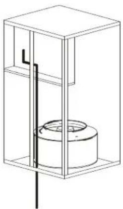
natural_image
Technical line drawing of a mechanical assembly with a cylindrical component inside a transparent enclosure (no text or symbols)Z
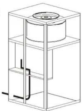
natural_image
Technical line drawing of a cylindrical mechanical component with internal structure and support brackets (no text or symbols)3
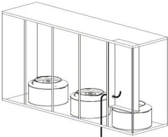
natural_image
Technical line drawing of a rectangular enclosure with three cylindrical components and vertical supports (no text or symbols)4
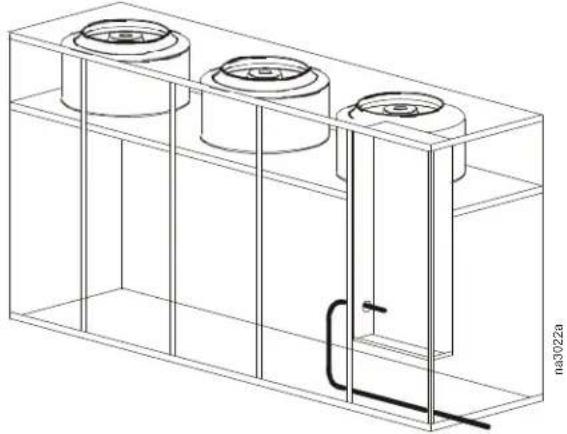
natural_image
Technical line drawing of a three-cylinder industrial tank with internal components and a pipe connection (no text or symbols)| Illustration Number Cabinet Size Airflow Direction | |
| 1 1 and 2 Downflow | |
| 2 1 and 2 Upflow | |
| 3 3 through 5 Downflow | |
| 4 3 through 5 Upflow | |
Piping Connections
Downflow Chilled Water Cooling Units
| Model PCW400 PCW660 | PCW900 PCW1100 PCW1500 | ||||
| In/Out Pipe Size | 35 mm(1 3/8 in) | 42 mm(1 5/8 in) | 54 mm(2 1/8 in) | 70 mm(2 3/4 in) | 70 mm(2 3/4 in) |

Note: The 70 mm (2 3/4 in) pipe size on models CPW1100 and CPW1500 is decreased after the screw connection to 64 mm (2 1/2 in) diameter for the external pipe connection.
PCW400
View from the bottom of the unit.
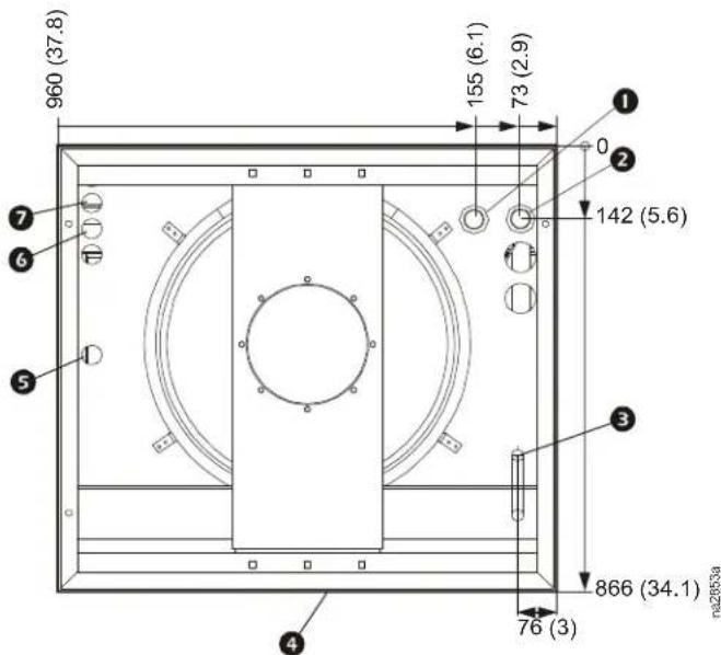
* Dimensions are in mm (in).
| Item Description | |
| 1 | Water outlet, 35 mm (1 3/8 in) ID |
| 2 | Water inlet, 35 mm (1 3/8 in) ID |
| 3 | Condensate drain, 25 mm (1 in) NPT |
| 4 | Rear of unit |
| 5 | Humidifier inlet, 6 mm (1/4 in) compression fitting |
| 6 | Control wire inlet, 10 mm (0.375 in) pilot hole |
| 7 | Power wire inlet, 10 mm (0.375 in) pilot hole |
View from the bottom of the unit
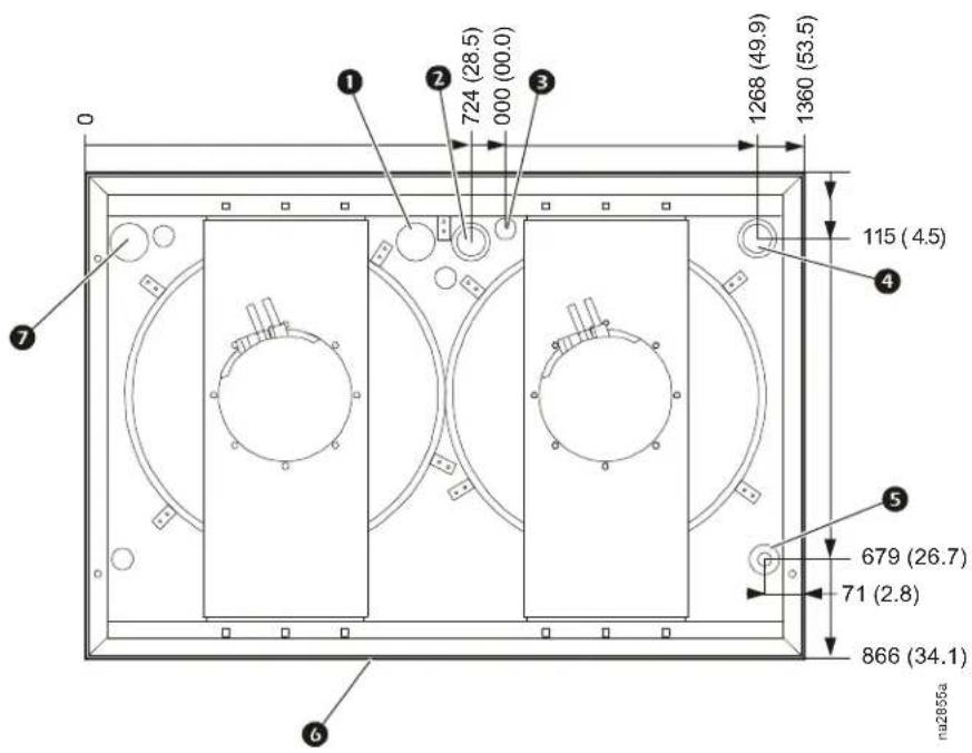
* Dimensions are in mm (in).
| Item Description | |
| 1 | Power wire inlet, 10 mm (0.375 in) pilot hole |
| 2 | Water outlet, 42 mm (1 5/8 in) ID |
| 3 | Control wire inlet, 10 mm (0.375 in) pilot hole |
| 4 | Water inlet, 42 mm (1 5/8 in) ID |
| 5 | Condensate drain, 25 mm (1 in) NPT |
| 6 | Rear of unit |
| 7 | Humidifier inlet, 6 mm (1/4 in) compression fitting |
PCW900
View from the bottom of the unit
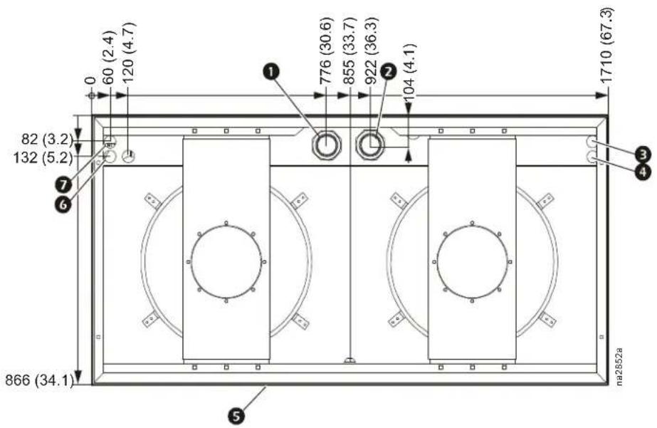
* Dimensions are in mm (in).
| Item Description | |
| 1 | Water inlet, 54 mm (2 1/8 in) ID |
| 2 | Water outlet, 54 mm (2 1/8 in) ID |
| 3 | Power wire inlet, 10 mm (0.375 in) pilot hole |
| 4 | Control wire inlet, 10 mm (0.375 in) pilot hole |
| 5 | Rear of unit |
| 6 | Humidifier inlet, 6 mm (1/4 in) compression fitting |
| 7 | Condensate drain, 25 mm (1 in) NPT |
PCW1100
View from the bottom of the unit.
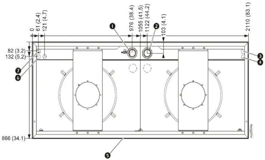
* Dimensions are in mm (in).
| Item Description | |
| 1 | Water inlet, 70 mm (2 3/4 in) ID |
| 2 | Water outlet, 70 mm (2 3/4 in) ID |
| 3 | Power wire inlet, 10 mm (0.375 in) pilot hole |
| 4 | Control wire inlet, 10 mm (0.375 in) pilot hole |
| 5 | Rear of unit |
| 6 | Humidifier inlet, 6 mm (1/4 in) compression fitting |
| 7 | Condensate drain, 25 mm (1 in) NPT |
PCW1500
View from the bottom of the unit.
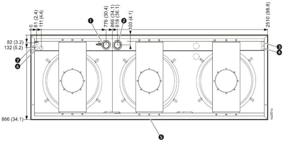
* Dimensions are in mm (in).
| Item Description | |
| 1 | Water inlet, 70 mm (2 3/4 in) ID |
| 2 | Water outlet, 70 mm (2 3/4 in) ID |
| 3 | Power wire inlet, 10 mm (0.375 in) pilot hole |
| 4 | Control wire inlet, 10 mm (0.375 in) pilot hole |
| 5 | Rear of unit |
| 6 | Humidifier inlet, 6 mm (1/4 in) compression fitting |
| 7 | Condensate drain, 25 mm (1 in) NPT |
Upflow Chilled Water Cooling Units
On upflow cooling units the supply and return pipes and power cables can be introduced from either the left or right side through openings in the side wall. The actual connection points are on the right side.
Left Side Connections
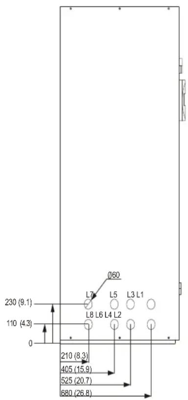
Right Side Connections
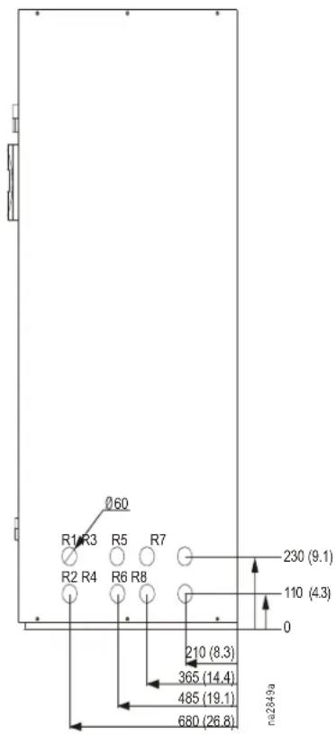
Dimensions are in mm (in).
| Model PCW | 400 PCW660 P | CW900 PCW1100 PCW1500 | ||
| In/Out Pipe Size | 35 mm(1 3/8 in) | 42 mm(1 5/8 in) | 54 mm(2 1/8 in) | 70 mm(2 3/4 in) |
| Left Side Openings Used | L1, L2, L3, L4,L5, L6 | L1, L2, L3, L4,L5, L6 | L1, L2, L3, L4,L5, L6 | L1, L2, L3, L4,L5, L6 |
| Right Side Openings Used | R1, R2, R3, R4,R5, R6 | R3, R4, R5, R6 R | 1, R2, R3, R4,R5, R6 | R1, R2, R3, R4 R1, R2, R3, R4 |

Note: The 70 mm (2 3/4 in) pipe size on models CPW1100 and CPW1500 is decreased to 64 mm (2 1/2 in) diameter after the screw connection for the external pipe connection.
Refrigerant Piping
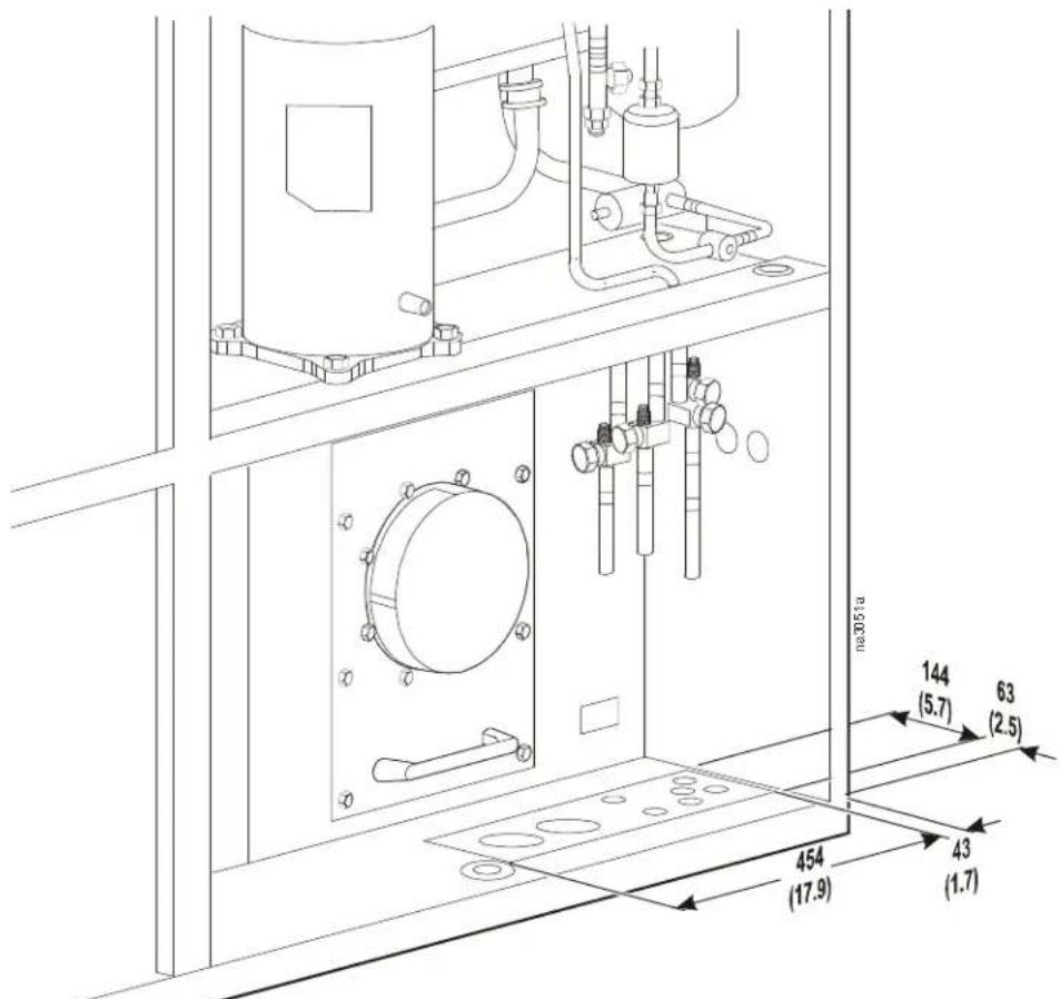
Dimensions in mm (in).
| Model | PA2111 circuit | PA3111 circuit | PA4522 circuits | PA6122 circuits | PA8622 circuits |
| Pressure Line | 16 mm (5/8 in) | 22 mm (7/8 in) | 16 mm(5/8 in) | 22 mm (7/8 in) | 22 mm (7/8 in) |
| Liquid Line | 12 mm (1/2 in) | 16 mm (5/8 in) | 22 mm (7/8 in) | 16 mm (5/8 in) | 16 mm (5/8 in) |
Considerations
The refrigerant connections are located near the compressor and are labelled pressure pipe and liquid pipe. Models containing two circuits will be labelled pressure pipe 1 and pressure pipe 2.
To ensure oil return in ascending hot gas lines, particularly at partial load, the minimum refrigeration capacity must not fall below the value on the table below.
| Minimum refrigeration outputs required for oil transportation in rising pressure lines for R407C refrigerant at dew point of 48°C (118.4°F) | ||||||
| Pipe Diameter mm (in) | 15 (5/8) 18 | (3/4) 22 (7/8) 28 (1 1/8) | 35 (1 3/8) 42 | (1 5/8) | ||
| Refrigerant Capacity kW (MBH) | 4.41 (15) | 5.17 (17.7) | 7.14 (24.4) | 10.0 (34.2) | 16.58 (56.6) | 25.9 (88.4) |
The horizontal lines must always be routed with a slope towards the condenser.
Establish the shortest route for pipework from the unit to the condenser.
InRoom Guide Specifications
PART 1 GENERAL
1.01 SUMMARY
A. The InRoom environmental control system shall be designed specifically for precision temperature and humidity control applications. It will automatically monitor and control heating, cooling, humidifying, dehumidifying, and filtering functions for the conditioned space. The system shall be built to the highest quality engineering and manufacturing standards, and shall be floor mounted and configured for ____(up/down) discharge of conditioned airflow, with draw-through air pattern, to provide uniform air distribution over the entire face of the coil.
1.02 DESIGN REQUIREMENTS
A. The system shall be as described in the following specification as manufactured by APC.
- Model:
- Total cooling capacity: kW (MBH)
- Sensible cooling capacity: kW (MBH)
- Return air temperature: ^ C ( ^ F) DB
- Return air temperature: ____ °C (°F) WB
- Humidity: ____ % RH
- Air quantity: ____ L/s (CFM)
- External Static Pressure: ____ Pa (PSI)
- Humidifier capacity: ____ kg/hr (lb/hr)
- Electrical supply: ____ V, ____ ph, ____ HZ
1.03 SUBMITTALS
A. Submittals shall be provided with the proposal and shall include: capacity data, electrical data, physical data, electrical connection drawing and piping connection drawing.
1.04 QUALITY ASSURANCE
A. The system shall be completely factory-tested prior to shipment. Testing shall include, but not be limited to: complete pressure and leak testing to ensure system integrity to include controls calibration and settings. Each system shall ship with a completed test report to verify completion of factory testing procedure. The system shall be ETL/CETL, NTRL listed, MCA, and the electrical system shall be UL Listed to UL 1995 and CSA 22.2 No. 236.
1.05 WARRANTY
A. 1 year parts without factory start-up and 1 year parts and labor with factory start-up.
PART 2 PRODUCT
2.01 STANDARD COMPONENTS
A. CABINET CONSTRUCTION
- Exterior panels: Shall be 16 gauge steel sheet metal for maximum strength. All exterior panels and frame are powder coated for durability. Front panels shall have removable hinges with a locking handle. The side panels are double wall construction with insulation between. Interior panel wall shall be insulated with 1/2 in (1.5 lb) density fiber insulation. Insulation shall be completely protected from the air stream by the panel wall or air blocks. Exterior frame and panel color shall have color values: L = 14.02, a = 0.13, b = 3.68. Main bezel color shall have color values: L = 13.44, a = 0.43, b = -2.63.
- Frame: Shall be constructed of welded 16 gauge formed steel for maximum strength.
- All units shall have full service access from the front, allowing the units to be placed side by side.
B. ELECTRONICALLY COMMUTATED (EC) FANS
- Electronically commutated (EC) Fans: The cooling unit shall be equipped with EC fan modules that have anti-vibration mountings to isolate each fan module from the structure of the cooling unit. The cooling unit shall be configured with a draw-through air pattern, to provide uniform air flow over the entire face of the coil.
C. REFRIGERATION COMPONENTS
- Dual Circuit Refrigeration System: The system shall operate under the coordination of the main controller. Suction and discharge pressures shall be monitored and electronically controllable. Each refrigeration system shall consist of a fully-protected scroll compressor, evaporator coil mounted over an anti-fungal, formed-plastic condensate drip pan, electronic expansion valve, hot gas bypass valve, filter-drier, sight glass, high pressure switch, and low pressure switch.
- Scroll Compressors: The unit shall contain scroll compressors for optimized performance, efficiency and reliability. The heavy-duty scroll compressors shall be designed for year-round usage. Scroll compressors shall have Advanced Scroll Temperature Protection (ASTP) to protect the Scroll Compressor from excessively high discharge gas temperatures. Compressor crankcase heaters shall be a standard feature for all units with the Scroll Technology.
- Electronic Expansion Valve: The unit shall contain an electronic expansion valve that is used to modulate the amount of refrigerant flow within the system. The EEV shall be constructed of stainless steel with ceramic slide and port parts for highly accurate flow and minimal wear. EEV has a fast reaction time (1.5 seconds), optimizing saturation of the evaporator coil.
D. CONTROLLER
- Controller: Shall be standard on each unit and provide precision control for the demanding requirements of Mission Critical Environments.
- Monitoring and Configuration: The display shall allow monitoring and configuration of the precision air conditioning unit through a menu-based control. Functions include status reporting, setup, and temperature and humidity set points. Three LEDs report the operational status of the connected precision air conditioning unit.
- Controls: The microprocessor shall come equipped with control keys that allow the user to navigate between menus, to select menu items, and to input alphanumeric information.
- Alarms: The microprocessor controller shall activate a visible and audible alarm in the occurrence of any of the following events:
a. Local Stop
b. Compressor Low Pressure
c. Compressor Failure
d. E-heating Failure
e. Humidifier Failure
f. Humidifier 5uS
g. Humidifier 20uS
h. Fan Error
i. Filter Clogged
j. External Alarm
k. Pump Failure
- Drycooler Failure
m. Water Detector
n. Room Temp Too High
o. Room Humidity Too High
p. Supply Temp Too High
q. Supply Humidity Too High
r. Room Temp Too Low
s. Room Humidity Too Low
t. Supply Temp Too Low
u. Supply Humidity Too Low
v. Water Temp Too High
w. Water Temp Too Low
x. Fire/Smoke Detector
y. Sensor Failure
z. Sensor Broken
- Logging: The microprocessor controller shall log and display the 200 most recent events and alarms. Each alarm log shall contain time and date stamp as well as operating conditions at the time of occurrence. The controller shall display the run time hours for major components (compressors, heaters, humidifier, and blower motors).
E. ELECTRICAL PANEL
- The control voltage shall be 24 VAC, class 2 circuit. The electrical panel shall contain contactors, starters, overload protection devices, and input power disconnects. The panel shall be located in the front of the unit for available access.
F. EVAPORATOR COIL/CONDENSATE PAN
-
The evaporator coil shall use aluminum fins and rifle-bored copper tubes. The coil end-supports shall be galvanized steel. To enhance dehumidification, the modular system shall utilize dual distributors on one circuit of the refrigeration system. The condensate pan shall be thermal formed, anti-fungal, non-ferrous material for higher indoor air quality.
-
The condensate pan shall have a UL-required overflow protection pipe. The overflow piping shall extend from the condensate pan to the base pan of the unit and allow for optional field piping as a gravity drain.
G. FILTERS (30%)
- The air filters shall be 30% efficient per ASHRAE Standard 52.1-92, UL Class 2. The full 102 mm (4 in) deep, pleated filters shall be replaceable from the front of the unit.
H. PROGRAMMABLE INPUT/OUTPUT INTERFACE MODULE
- The unit shall provide field connection through a system-programmable input/output module. Each interface module shall be programmable with outputs that can map from any system alarm through the microprocessor controller. Inputs shall be capable of mapping to outputs as a system alarm or custom alarm.
I. REFRIGERATION SYSTEM MONITORING
- The system shall report real time monitoring of both suction and discharge pressures to the controller. Pressures shall be logged and displayed at the proper menu selection on the controls when an alarm condition occurs.
J. MAIN POWER DISCONNECT
-
A factory-installed, main power disconnect switch shall disconnect all high-voltage power to the unit if necessary. The disconnect switch shall be accessible without removing the electric box cover.
-
If the cooling unit is equipped with dual power sources, two power disconnect switches shall be accessible without removing the electric box cover.
K. GROUP CONTROL
- Group control shall allow up to 16 units to communicate with each other for redundancy, demand fighting prevention and mode assistance. Global sharing of certain settings shall require a twisted pair of shielded wiring for interconnection.
L. NETWORK CABLE - REDUNDANT GROUP CONTROL
- A twisted pair of shielded wire no longer than 20 m shall be required. The cable shall be used to interconnect multiple cooling units in a redundant group and to connect the Network Management Card to the LAN.
M. NETWORK MANAGEMENT CARD
- The Network Management Card shall permit multi-level access to monitoring, control, and event notification features over the user's network.
N. ADDITIONAL PROGRAMMABLE INPUT/OUTPUT (I/O)
- The heart of the control system is the I/O controller on which up to 4 EAIO/EDIO boards shall be connected for additional inputs and outputs. The InRoom Controller Manual has a detailed description of inputs and outputs for InRoom configuration.
| A-In A | -Out D-In | D-Out | ||
| IOC Board 5 4 | 1 | 7 | ||
| EAIO Board | 4 | 4 | 1 | 1 |
| EDIO Board | 1 | 1 | 8 | 6 |
O. EVAPORATOR FREEZE PROTECTION
- Suction pressure shall be actively monitored by two individual sensors and controlled by the microprocessor to calculate the opening of the electronic expansion valve (EEV), eliminating the risk of condensate freeze-up on the evaporator.
P. PREDICTIVE FAILURE WARNINGS
- Several components within the unit, such as the compressor, blower, heater, and humidifier, shall provide a warning through the display interface that service is needed.
Q. STEAM GENERATING HUMIDIFIER
- The humidifier shall be able to modulate capacity. The humidifier shall be self-contained, steam-generating, factory-piped and wired, with a disposable cylinder and automatic solid-state control circuit. Humidifier canisters are replaceable. The humidifier controller shall communicate directly to the microprocessor controller and provide complete status and control at the display interface.
R. SILICONE CONTROLLED RECTIFIER (SCR) ELECTRIC REHEAT
- Reheat elements shall be low watt density, wired for three-phase, loaded equally on all three phases and electrically and thermally protected by both automatic and manual reset thermal cutouts. Reheat capacity shall be ____ MBH, ____ kW, SCR controlled. Reheat coils shall be stainless steel, fin, and tube construction.
S. HIGH LIFT, SINGLE FLOAT CONDENSATE PUMP
- The shipped loose, field-installed and wired condensate pump shall pump 1275 L/s (337 GPH) at 6.09 m (20 ft) head. The tank capacity shall be 3.78 L/s (1 USG).
T. BRAZED PLATE CONDENSER
- Water and glycol cooled systems shall employ a brazed plate heat exchanger. The condenser shall be equipped with clean-out plugs.
U. WATER REGULATING VALVES
- Water and glycol cooled systems shall utilize two-way or three-way valves to regulate the amount of water or glycol supplied to the condenser in response to refrigerant discharge pressure. The standard valve pressure rating shall be 2758 kPa (400 psi).
V. DISCHARGE DUCT COLLAR
- A 25.4 mm (1 in) duct flange shall be provided for field installation on a unit to provide convenient connection to external ductwork.
2.02 OPTIONAL COMPONENTS
A. FLOORSTAND
- The heavy gauge floor stand shall raise the unit above the subfloor to match the height of the raised floor. Heights are available from 254 mm (10 in) to 610 mm (24 in) with 76 mm (3 in) increments and shall be adjustable +/- 1.5 in. Adjustment is provided by threaded pedestals. Vibration-absorbing pads shall be included with all floorstands and are recommended with every installation.
- Seismic floorstands shall be available in 305 mm (12 in), 457 mm (18 in), and 610 mm (24 in) heights for areas where earthquakes are a concern.
B. PLENUM
- Upflow discharge plenums (60 Hz only) shall mount on top of an upflow cooling unit to direct and distribute conditioned air. The plenum shall be manually adjustable and provided with double deflecting grilles. Plenums are a fixed height of 500 mm (19.6 in).
- Downflow discharge base plenums (50 Hz and 60 Hz) shall sit beneath the downflow cooling unit to direct conditioned air from front openings. Models available include dampers, grills, or flexible duct connections. Plenums are a fixed height of 450 mm (17.7 in).
C. SMOKE DETECTOR
- A smoke detector shall be factory-installed to sense concentrations of smoke and send a signal to the main controller, shutting down the unit and activating a visual and audible alarm.
D. SPOT WATER DETECTOR (50Hz and 60Hz)
- The spot water detector shall sense water and send an alarm signal to the display interface to broadcast an alarm and shutdown the cooling unit. The water detector shall ship loose for field installation.
- The water detector shall be provided with 5 m (15 ft) of wire.
E. CABLE WATER DETECTOR (60Hz only)
- A leak detection sensing cable shall be shipped loose with the unit. If water or other conductive liquids contact the cable anywhere along its length, the main controller visually and audibly annunciates the leak.
- The detector shall be provided with 6 m (20 ft) of cable.
F. FLOW SWITCH
- A single pole, double throw, flow switch shall moderate fluid flow when it exceeds or drops below the set flow rate. The flow switch shall ship loose for field installation.
G. HOT GAS BYPASS VALVE
- The 60 Hz cooling unit shall contain a spring loaded, thermally driven hot gas bypass valve (HGBV). Activation of the HGBV shall maintain the evaporator coil temperature during low load conditions to prevent condensate from freezing on the surface of the evaporator coil and to protect the compressor from excessive cycling.
- The 50 Hz cooling unit shall contain an electronically controlled HGBV, which is controlled by a 0-10V signal to maintain the refrigerant capacity in the range of 50 to 100% of the nominal capacity with constant compressor operation and constant evaporation temperature.
H. SECONDARY POWER SUPPLY
- 50 Hz cooling units shall have a secondary power supply option that is controlled automatically to switch from a main power supply to a secondary power source in the event of a power outage using a digital electronic controller.
- 50 Hz cooling units shall have a secondary power supply option that is controlled manually. The cooling unit may be manually switched from the main power supply to a secondary power source at a separate external switch using a digital electronic controller.
- 60 Hz cooling units shall have a secondary power supply option that is controlled automatically to switch from a main power supply to a secondary power source in the event of a power outage using a mechanical controller.
- 60 Hz cooling units shall have a secondary power supply option that is controlled manually. The cooling unit may be manually switched from the main power supply to a secondary power source at a separate external switch using a mechanical controller.
PART 3 INDIVIDUAL SYSTEMS
3.01 AIR-COOLED
A. The indoor unit shall consist of an evaporator section including evaporator coil, EC fan package, controls, electrical section, and compressor.
3.02 CONDENSER
A. Outdoor Propeller Fan Condenser (60Hz): The outdoor condenser cabinet shall be constructed of 2 mm (0.08 in) aluminum, with heavy gauge galvanized steel support legs. The condenser cabinet shall house the condenser coil, fan(s), fan guard(s), and condenser motor control and enabling box. The condenser motor control shall be approved by the National Electrical Manufacturers Association (NEMA) and be constructed using 3R (Reduce, Recycle, Reuse) technology. The condenser shall have copper tubes expanded into aluminum fins. The headers and connections shall be copper. The coil shall be pressure-tested and sealed for shipment. The condenser motors shall have internal overload protection and operate on ____ V, ____ ph, 60 Hz power.
- (SA) -20° F Variable Fan Speed Control: The air-cooled system shall incorporate a low ambient variable speed fan head pressure control for year-round A/C system operation down to -29° C
(-20°F) DB minimum ambient temperature. Number one fan is speed controlled based on refrigerant discharge pressure. All remaining fan(s) are controlled by pressure fan cycling controls.
- (EC) -20° F Intelligent control: The air cooled system shall incorporate a low ambient variable speed fan head pressure control for year round A/C system operation down to -20° F DB minimum ambient air temperature. All fans shall be high efficient, electronically commutated EC axial fan(s). The control system shall be provided with refrigerant pressure transducer(s) to monitor refrigerant discharge pressure and control the EC fan(s) to the precise speed as needed to maintain design refrigerant discharge pressures.
B. Outdoor Propeller Fan Condenser (50Hz): The outdoor condenser casing shall be made of aluminum, and all structural supports, coil frame, motor drive supports, and mounting legs shall be made of galvanized steel. The condenser shall have copper tubes expanded into aluminum fins. Headers and connections shall be copper. The coil shall be pressure tested and sealed for shipment. The condenser motors shall have internal overload protection, and operate on ____ V, ____ ph, 50 Hz power. Motors shall be mounted inside the condenser casing for weather protection, and shall be wired to a terminal strip in a weatherproof panel on the unit. The direct drive, aluminum fan blade and painted steel hub assembly shall be protected by a heavy-gauge, vinyl-coated, steel-wire fan guard. On multiple units, each fan section shall be separated by full-width baffles to prevent bypass air. The condenser shall be sized for ____ °C (°F) ambient, and condensing temperature controls shall be fan speed for -29°C (-20°F) winter ambient.
C. Liquid Receivers: Each standard stock receiver shall conform to UL, CSA, or ASME requirements for 450 psi maximum working pressure. Models with an internal diameter under six inches shall be UL listed. All larger models shall be made according to ASME code and tagged appropriately.
-
All pumpdowns shall be calculated at 80% capacity of liquid.
-
Approximately 10% of pumpdown capacity shall be required to operate receiver properly.
3.03 WATER-COOLED
A. The water-cooled system shall consist of an evaporator section including evaporator coil, EC Fan package, controls, electrical section, compressor, and water-cooled condenser. The condenser shall be stainless steel brazed plate design and shall be controlled by 2- or 3-way valve. Maximum water pressure shall be 2758 kPa (400 psig).
3.04 GLYCOL-COOLED
A. The glycol-cooled system shall consist of an evaporator section including evaporator coil, EC Fan package, controls, electrical section, compressor, and glycol-cooled condenser. The condenser shall be stainless steel brazed plate design and shall be controlled by a 2- or 3-way valve. Maximum water pressure shall be 2758 kPa (400 psig).
3.05 PUMP PACKAGE
A. Single Pump Package: The pump package shall be comprised of a centrifugal pump in a vented enclosure. The controls shall be mounted on the fluid cooler. An expansion tank and Airtrol fitting shall be supplied for field installation. The pump size shall be sized for ____ L/m (GPM) at ____ m (ft) external head, and operate on ____ V, ____ ph, ____ Hz power.
B. Dual Pump Package: The dual pump package shall consist of two centrifugal pumps in an enclosure. Pump starters, automatic pump switch-over controls, lead-lag pump selector switch, separate fluid cooler fan and pump circuit breakers, Aquastat, and fan cycling contractor to control the fluid temperature shall be mounted on the fluid cooler. An expansion tank and Airtrol fitting shall be supplied for field installation. Each pump shall be sized for ____ L/m (GPM) at ____ m (ft) external head, and operate on ____ V, ____ ph, ____ Hz power.
3.06 ECONOMIZER
A. Glycol/ Water systems shall have the option of an economizer coil that is designed to reduce operating costs during mid to low ambient temperatures. The economizer cooling coil shall be copper tube, aluminum fin coil located in the return air before the evaporator coil. The economizer coil shall be rated at ____ kW (BTU/HR) sensible cooling capacity with a 7.2°C (45°F) entering glycol solution temperature. The economizer coil shall require ____ l/m (GPM) and the total unit pressure drop shall not exceed ____ kPa (feet of water), when in the economizer mode of operation.
3.07 MULTICOOL
A. Air systems shall have the option of a chilled water coil that is designed to be the primary cooling source to the backup direct expansion coil. The MultiCool (chilled water) coil shall be constructed with copper tubes and aluminum fins. It shall be located in the return air, before the evaporator coil. The MultiCool coil shall be rated at ____ kW (BTU/HR) sensible cooling capacity with 7.2°C (45°F) entering water temperature. The MultiCool coil shall require ____ l/m (GPM) of chilled water and the pressure drop shall not exceed ____ kPa (psig).
3.08 CHILLED WATER
A. The unit shall be piped in accordance with the highest commercial quality procedures. All exposed piping shall be insulated copper, type "L". All pipe forming shall be tool bent with proper bend radii to prevent tube flattening in the curve. The chilled water piping shall be insulated with closed cell neoprene thermal insulation. The chilled water flow shall be controlled by a 2- or 3-way valve with a 24 VDC Actuator.
3.09 FLUID COOLER
A. Outdoor Fluid Cooler: The fluid cooler casing shall be of aluminum, and all structural supports, coil frame, motor-drive supports, and mounting legs shall be made of galvanized steel. The fluid cooler coil shall have copper tubes expanded into aluminum fins. Headers and connections shall be copper. The coil shall be pressure-tested and sealed for shipment. The fluid cooler motors shall have permanently lubricated, sealed, ball bearings, and internal overload protection. Motors shall be mounted inside the fluid cooler casing for weather protection and wired to a terminal strip in a weatherproof panel on the unit. The direct-drive, aluminum fin blade and painted steel hub assembly shall be protected by a heavy-gauge, vinyl-coated, steel-wire fan guard. On multiple fan units, each fan section shall be separated by full-width baffles to prevent bypass air. The fluid cooler shall be sized for 35^ C ( 95^ F) ambient, and operate on ____ V, ____ ph, ____ Hz power.
One-Year Factory Warranty
The limited warranty provided by American Power Conversion (APC ^® ) in this Statement of Limited Factory Warranty applies only to products you purchase for your commercial or industrial use in the ordinary course of your business.
Terms of warranty
American Power Conversion warrants its products to be free from defects in materials and workmanship for a period of one year from the date of purchase. The obligation of APC under this warranty is limited to repairing or replacing, at its sole discretion, any such defective products. This warranty does not apply to equipment that has been damaged by accident, negligence or misapplication or has been altered or modified in any way. Repair or replacement of a defective product or part thereof does not extend the original warranty period. Any parts furnished under this warranty may be new or factory-remanufactured.
Non-transferable warranty
This warranty extends only to the original purchaser who must have properly registered the product. The product may be registered at the APC Web site, www.apc.com.
Exclusions
APC shall not be liable under the warranty if its testing and examination disclose that the alleged defect in the product does not exist or was caused by end user's or any third person's misuse, negligence, improper installation or testing. Further, APC shall not be liable under the warranty for unauthorized attempts to repair or modify wrong or inadequate electrical voltage or connection, inappropriate on-site operation conditions, corrosive atmosphere, repair, installation, start-up by non-APC designated personnel, a change in location or operating use, exposure to the elements, Acts of God, fire, theft, or installation contrary to APC recommendations or specifications or in any event if the APC serial number has been altered, defaced, or removed, or any other cause beyond the range of the intended use.
THERE ARE NO WARRANTIES, EXPRESS OR IMPLIED, BY OPERATION OF LAW OR OTHERWISE, OF PRODUCTS SOLD, SERVICED OR FURNISHED UNDER THIS AGREEMENT OR IN CONNECTION HEREWITH. APC DISCLAIMS ALL IMPLIED WARRANTIES OF MERCHANTABILITY, SATISFACTION AND FITNESS FOR A PARTICULAR PURPOSE. APC EXPRESS WARRANTIES WILL NOT BE ENLARGED, DIMINISHED, OR AFFECTED BY AND NO OBLIGATION OR LIABILITY WILL ARISE OUT OF, APC RENDERING OF TECHNICAL OR OTHER ADVICE OR SERVICE IN CONNECTION WITH THE PRODUCTS. THE FOREGOING WARRANTIES AND REMEDIES ARE EXCLUSIVE AND IN LIEU OF ALL OTHER WARRANTIES AND REMEDIES. THE WARRANTIES SET FORTH ABOVE CONSTITUTE APC'S SOLE LIABILITY AND PURCHASER'S EXCLUSIVE REMEDY FOR ANY BREACH OF SUCH WARRANTIES. APC WARRANTIES EXTEND ONLY TO PURCHASER AND ARE NOT EXTENDED TO ANY THIRD PARTIES.
IN NO EVENT SHALL APC, ITS OFFICERS, DIRECTORS, AFFILIATES OR EMPLOYEES BE LIABLE FOR ANY FORM OF INDIRECT, SPECIAL, CONSEQUENTIAL OR PUNITIVE DAMAGES, ARISING OUT OF THE USE, SERVICE OR INSTALLATION, OF THE PRODUCTS, WHETHER SUCH DAMAGES ARISE IN CONTRACT OR TORT, IRRESPECTIVE OF FAULT, NEGLIGENCE OR STRICT LIABILITY OR WHETHER APC HAS BEEN ADVISED IN ADVANCE OF THE POSSIBILITY OF SUCH DAMAGES. SPECIFICALLY, APC IS NOT LIABLE FOR ANY COSTS, SUCH AS LOST PROFITS OR REVENUE, LOSS OF EQUIPMENT, LOSS OF USE OF EQUIPMENT, LOSS OF SOFTWARE, LOSS OF DATA, COSTS OF SUBSTITUENTS, CLAIMS BY THIRD PARTIES, OR OTHERWISE.
NO SALESMAN, EMPLOYEE OR AGENT OF APC IS AUTHORIZED TO ADD TO OR VARY THE TERMS OF THIS WARRANTY. WARRANTY TERMS MAY BE MODIFIED, IF AT ALL, ONLY IN WRITING SIGNED BY AN APC OFFICER AND LEGAL DEPARTMENT.
Warranty claims
Customers with warranty claims issues may access the APC customer support network through the Support page of the APC Web site, www.apc.com/support. Select your country from the country selection pull-down menu at the top of the Web page. Select the Support tab to obtain contact information for customer support in your region.
Warranty Procedures
Claims
To obtain service under the warranty, contact APC Customer Support (see the back cover of this manual for contact information). You will need the model number of the Product, the serial number, and the date purchased. A technician will also ask you to describe the problem. If it is determined that the Product will need to be returned to APC, you must obtain a returned material authorization (RMA) number from APC Customer Support. Products that must be returned must have the RMA number marked on the outside of the package and must be returned with transportation charges prepaid. If it is determined by APC Customer Support that on-site repair of the Product is allowed, APC will arrange to have APC authorized service personnel dispatched to the Product location for repair or replacement, at the discretion of APC.
Parts
- APC warrants the parts of their systems for 1 year from the date of commissioning or 18 months from the ship date. This warranty only covers the cost of the part and not the labor for installation.
- Calls for warranty parts requests need to have specific unit information (serial number, model number, job number) to allow proper identification and processing of the warranty part transaction.
- A purchase order may be required to issue any warranty parts. An invoice will be sent once the parts are shipped to the field. You have 30 days to return the defective parts to APC. After 30 days, the warranty invoice will be outstanding, and payment of the invoice will be expected in full.
- Return authorization documentation will be sent with the replacement part. This documentation must be sent back with the defective part to APC for proper identification of the warranty return. Mark the warranty return number on the outside of the package.
- After the part has been received at APC, we will determine the status of the credit based on the findings of the returned part. Parts that are damaged from lack of maintenance, misapplication, improper installation, shipping damage, or acts of man/nature will not be covered under the parts warranty.
- Any warranty parts request received before 1:00 PM EST will be shipped same-day standard ground delivery. Any costs associated with Next Day or Airfreight will be the responsibility of the party requesting the part.
- Return freight of warranty parts to APC is the responsibility of the party returning the part.
APC®
www.apc.com
APC Worldwide Customer Support
Customer support for this or any other APC product is available at no charge in any of the following ways:
- Visit the APC Web site to access documents in the APC Knowledge Base and to submit customer support requests.
- www.apc.com (Corporate Headquarters)
Connect to localized APC Web sites for specific countries, each of which provides customer support information. - www.apc.com/support/
Global support searching APC Knowledge Base and using e-support.
- Contact the APC Customer Support Center by telephone or e-mail.
- Local, country-specific centers: go to www.apc.com/support/contact for contact information.
For information on how to obtain local customer support, contact the APC representative or other distributors from whom you purchased your APC product.
© 2009 APC by Schneider Electric. APC, the APC logo, and InRoom are owned by Schneider Electric Industries S.A.S., American Power Conversion Corporation, or their affiliated companies. All other trademarks are property of their respective owners.
- American Power Conversion Legal Disclaimer
- Contents
- Overview....1
- 60Hz Performance Specifications 23
- 50Hz Performance Specifications 45
- General Specifications 63
- InRoom Guide Specifications 74
- Warranty 84
- General
- Models
- Room Air Distribution
- Configurations
- Compliance Approval
- Standard Features
- Optional Features
- Scalable Solution for Critical Environments
- Temperature and Humidity Design Conditions
- Air Quality
- Low Humidity
- High Humidity
- High & Low Temperature
- Efficiency and Reliability
- APC InRoom - The Right Solution
- Dedicated Dehumidification Cycle
- Insulated Panels
- Electronically Commutated (EC) Fans
- Electrical Panel
- Main Power Disconnect Switch
- Network Management Card
- Refrigeration System and Compressor
- Mains Automatic Transfer Switches
- Duct Flange
- Evaporative Freeze Protection
- Redundant Group Control
- 30% ASHRAE 52.1 Filters
- Condenser (Direct Expansion units only)
- Humidifier
- Electric Reheat
- Spot Water Detector
- Smoke Detector
- Hot Gas Bypass Valve
- Cable Leak Detector (60 Hz only)
- Floorstand
- Plenums
- Base Plenum
- Water Regulating Valves
- Extreme Low Temperature Kit (Direct Expansion units only)
- Condensate Pump
- Upflow Discharge Plenums for 50 Hz and 60 Hz InRoom Cooling Units
- Note:
- Bowling Alley Floorstands for InRoom 60Hz Cooling Units
- Floorstands for InRoom 50 HzCooling Units
- Condensers
- Receivers
- Display Interface
- Logging
- Control Type
- Functions
- Open Architecture
- Alarms
- InRoom Model Sizes
- InRoom Cooling Unit Configurations
- Fluid Cooled (Glycol)
- Chilled Water
- Air Cooled (DX)
- 60Hz Performance Specifications
- MultiCool – Air Cooled (DX) with CW – 60Hz
- Fluid Cooled (Glycol 0%) with CW - 60Hz
- Fluid Cooled (Glycol 40%) with CW - 60Hz
- Fluid Cooled (Glycol 40%) with Economizer - 60Hz
- 60Hz InRoom Electrical Specifications
- 50Hz Performance Specifications
- Air Cooled (DX) System - 50Hz
- MultiCool - Air Cooled (DX) with CW - 50Hz
- Fluid Cooling (Glycol 40%) – 50Hz
- Fluid Cooled (Glycol 0%) - 50Hz
- Fluid Cooled (Glycol 40%) with CW - 50Hz
- Fluid Cooled (Glycol 40%) with Economizer - 50Hz
- 50Hz InRoom Electrical Specifications
- General Specifications
- Technical Specifications
- Application Limits
- Design Conditions
- Transporting and Storage
- Delivery of the unit
- Moving the unit
- Storage
- Guidelines for Installation
- Room preparation
- Unit location
- Service access
- Receiving the unit
- Rigging
- Utility connections
- Power to the unit
- Chilled Water Power Supply Inlet Location
- Piping Connections
- PCW400
- PCW900
- PCW1100
- PCW1500
- Upflow Chilled Water Cooling Units
- Refrigerant Piping
- Considerations
- InRoom Guide Specifications
- PART 1 GENERAL
- SUMMARY
- DESIGN REQUIREMENTS
- SUBMITTALS
- QUALITY ASSURANCE
- WARRANTY
- PART 2 PRODUCT
- STANDARD COMPONENTS
- CABINET CONSTRUCTION
- ELECTRONICALLY COMMUTATED (EC) FANS
- REFRIGERATION COMPONENTS
- CONTROLLER
- ELECTRICAL PANEL
- EVAPORATOR COIL/CONDENSATE PAN
- FILTERS (30%)
- PROGRAMMABLE INPUT/OUTPUT INTERFACE MODULE
- REFRIGERATION SYSTEM MONITORING
- MAIN POWER DISCONNECT
- GROUP CONTROL
- NETWORK CABLE - REDUNDANT GROUP CONTROL
- NETWORK MANAGEMENT CARD
- ADDITIONAL PROGRAMMABLE INPUT/OUTPUT (I/O)
- EVAPORATOR FREEZE PROTECTION
- PREDICTIVE FAILURE WARNINGS
- STEAM GENERATING HUMIDIFIER
- SILICONE CONTROLLED RECTIFIER (SCR) ELECTRIC REHEAT
- HIGH LIFT, SINGLE FLOAT CONDENSATE PUMP
- BRAZED PLATE CONDENSER
- WATER REGULATING VALVES
- DISCHARGE DUCT COLLAR
- OPTIONAL COMPONENTS
- FLOORSTAND
- PLENUM
- SMOKE DETECTOR
- SPOT WATER DETECTOR (50Hz and 60Hz)
- CABLE WATER DETECTOR (60Hz only)
- FLOW SWITCH
- HOT GAS BYPASS VALVE
- SECONDARY POWER SUPPLY
- PART 3 INDIVIDUAL SYSTEMS
- AIR-COOLED
- CONDENSER
- WATER-COOLED
- GLYCOL-COOLED
- PUMP PACKAGE
- ECONOMIZER
- MULTICOOL
- CHILLED WATER
- FLUID COOLER
- One-Year Factory Warranty
- Terms of warranty
- Non-transferable warranty
- Exclusions
- Warranty claims
- Warranty Procedures
- Claims
- Parts
- APC®
- www.apc.com
- APC Worldwide Customer Support
Brand : APC
Model : InRoom Condenser
Category : Computer Cooling Component