
ACRC600P - Computer Cooling Component APC - Free user manual and instructions
Find the device manual for free ACRC600P APC in PDF.


| Product Type | Computer Cooling Component (In-Row Cooling Unit) |
| Brand | APC |
| Model | ACRC600P |
| Dimensions (H x W x D) | 78.7 x 23.6 x 43.3 in (2000 x 600 x 1100 mm) |
| Weight | Approx. 550 lbs (250 kg) |
| Cooling Capacity | Up to 60 kW |
| Power Supply | 208V / 230V, 3-phase, 50/60 Hz |
| Refrigerant | R410A |
| Airflow | Variable speed fans, up to 4000 CFM |
| Control Interface | LCD touchscreen with network management |
| Operating Temperature Range | 60°F to 95°F (15°C to 35°C) |
| Humidity Range | 20% to 80% non-condensing |
| Noise Level | ≤ 65 dBA at full load |
| Installation Type | In-row, floor standing |
| Certifications | UL, CE, RoHS |
| Maintenance | Replace air filters every 6 months; clean condenser coils annually |
| Safety Features | Overheat protection, refrigerant leak detection, emergency shutdown |
| Spare Parts | Fan assemblies, filter kits, controller boards, compressor kits |
| Repairability | Modular design; field-replaceable components with service access |
| Warranty | Standard 2 years, extended available |
| Compliance | ASHRAE, ENERGY STAR |
Frequently Asked Questions - ACRC600P APC
User questions about ACRC600P APC
0 question about this device. Answer the ones you know or ask your own.
Ask a new question about this device
Download the instructions for your Computer Cooling Component in PDF format for free! Find your manual ACRC600P - APC and take your electronic device back in hand. On this page are published all the documents necessary for the use of your device. ACRC600P by APC.
USER MANUAL ACRC600P APC
InRow® Chilled Water Air Conditioners
InRow® RC
ACRC600, ACRC601, ACRC602, ACRC600P, ACRC601P, ACRC602P
990-5790A-001
Publication Date: October 2017
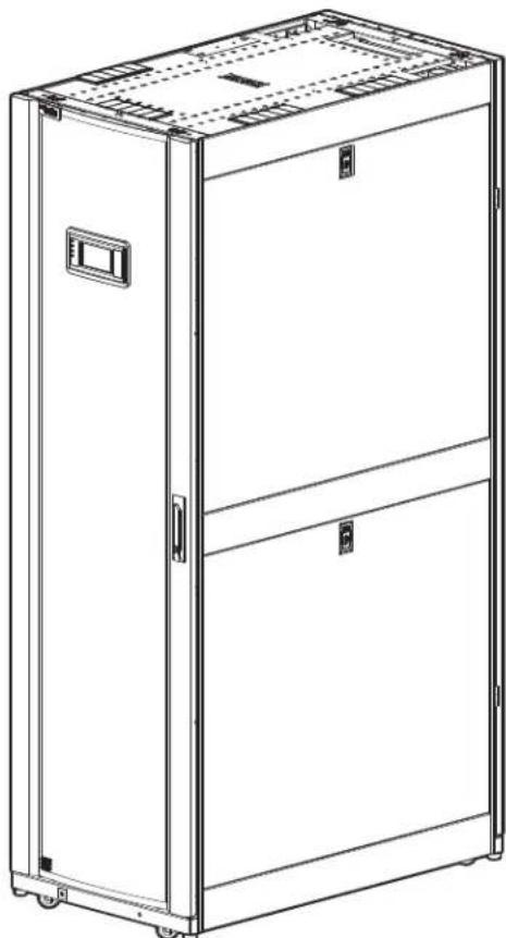
natural_image
Line drawing of a two-tiered industrial cabinet or enclosure with front panel and door (no text or symbols)Schneider Electric IT Corporation Legal Disclaimer
The information presented in this manual is not warranted by the Schneider Electric IT Corporation to be authoritative, error free, or complete. This publication is not meant to be a substitute for a detailed operational and site specific development plan. Therefore, Schneider Electric IT Corporation assumes no liability for damages, violations of codes, improper installation, system failures, or any other problems that could arise based on the use of this Publication.
The information contained in this Publication is provided as is and has been prepared solely for the purpose of evaluating data center design and construction. This Publication has been compiled in good faith by Schneider Electric IT Corporation. However, no representation is made or warranty given, either express or implied, as to the completeness or accuracy of the information this Publication contains.
IN NO EVENT SHALL SCHNEIDER ELECTRIC IT CORPORATION, OR ANY PARENT, AFFILIATE OR SUBSIDIARY COMPANY OF SCHNEIDER ELECTRIC IT CORPORATION OR THEIR RESPECTIVE OFFICERS, DIRECTORS, OR EMPLOYEES BE LIABLE FOR ANY DIRECT, INDIRECT, CONSEQUENTIAL, PUNITIVE, SPECIAL, OR INCIDENTAL DAMAGES (INCLUDING, WITHOUT LIMITATION, DAMAGES FOR LOSS OF BUSINESS, CONTRACT, REVENUE, DATA, INFORMATION, OR BUSINESS INTERRUPTION) RESULTING FROM, ARISING OUT, OR IN CONNECTION WITH THE USE OF, OR INABILITY TO USE THIS PUBLICATION OR THE CONTENT, EVEN IF SCHNEIDER ELECTRIC IT CORPORATION HAS BEEN EXPRESSLY ADVISED OF THE POSSIBILITY OF SUCH DAMAGES. SCHNEIDER ELECTRIC IT CORPORATION RESERVES THE RIGHT TO MAKE CHANGES OR UPDATES WITH RESPECT TO OR IN THE CONTENT OF THE PUBLICATION OR THE FORMAT THEREOF AT ANY TIME WITHOUT NOTICE.
Copyright, intellectual, and all other proprietary rights in the content (including but not limited to software, audio, video, text, and photographs) rests with Schneider Electric IT Corporation or its licensors. All rights in the content not expressly granted herein are reserved. No rights of any kind are licensed or assigned or shall otherwise pass to persons accessing this information.
This Publication shall not be for resale in whole or in part.
Table of Contents
Safety....5
Important Safety Information 5
Safety Notices During Installation. 6
General Information......8
Inspecting the Equipment 8
Storing the Equipment Before Installation 8
Moving the Equipment 8
Moving the equipment to its final location 8
Waste Disposal....9
Waste Electrical and Electronic Equipment (WEEE) disposal . 9
Model Identification....9
Component Identification 10
Install kit inventory 10
Exterior components 11
Interior components (front) 12
Interior components (rear) 14
Electrical panel 15
Main controller board 17
17
Display interface 18
Piping Diagrams 19
Connections 20
Pre-Installation 21
Room preparation 21
Air distribution 21
Incoming power supply requirements 22
Automatic transfer switch (ATS) 22
Dimensions and Weights 23
Dimensions 23
Weights 23
Service access 23
Piping and Power Access Locations 24
Top piping and power access locations (top view) ..... 24
Bottom piping and power access locations (bottom view) .... 25
Installation....26
Removing the Doors and Panels 26
Removing the front door 26
Removing the rear doors 27
Removing and installing the side panels 28
Removing the electrical panel cover 29
Joining the Equipment to Enclosures.... 30
Joining to NetShelter™ SX enclosures 30
Joining to NetShelter VX and VS enclosures 30
Leveling the Equipment 31
Mechanical Connections 32
Top water piping 32
Bottom water piping 33
Humidifier (ACRC60xP units only) 34
Condensate overflow 35
Leak sensor (optional) 36
Filling and Purging the Unit 37
Chiller.... 38
Cooling unit requirements 38
Electrical Connections 38
Customer interface connections 39
Description of customer interface connectors 40
Rack temperature sensors 41
Water outlet temperature sensors 42
Communication connections 42
Network port 44
Power Connections 44
Wiring configurations 45
Install power cords (ACRC600 and ACRC602 only) ..... 45
Top routing 46
Bottom routing 46
Strain relief (ACRC602 and ACRC602P only) 47
Voltage selection—ACRC60x units 48
Voltage selection—ACRC60xP units 49
Important Safety Information
Read the instructions carefully to become familiar with the equipment before trying to install, operate, service, or maintain it. The following special messages may appear throughout this manual or on the equipment to warn of potential hazards or to call attention to information that clarifies or simplifies a procedure.

The addition of this symbol to a Danger or Warning safety label indicates that an electrical hazard exists which will result in personal injury if the instructions are not followed.

This is the safety alert symbol. It is used to alert you to potential personal injury hazards. Obey all safety messages that follow this symbol to avoid possible injury or death.
DANGER
DANGER indicates an imminently hazardous situation which, if not avoided, will result in death or serious injury.
WARNING
WARNING indicates a potentially hazardous situation which, if not avoided, can result in death or serious injury.
CAUTION
CAUTION indicates a potentially hazardous situation which, if not avoided, can result in minor or moderate injury.
NOTICE
NOTICE addresses practices not related to physical injury including certain environmental hazards, potential damage or loss of data.
Safety Notices During Installation
Read and adhere to the following important safety considerations when working with this equipment.

DANGER
HAZARD OF ELECTRIC SHOCK, EXPLOSION, OR ARC FLASH
- Apply appropriate personal protective equipment (PPE) and follow safe electrical work practices. See NFPA 70E or CSA Z462.
- This equipment must be installed and serviced by qualified personnel only.
- Turn off all power supplying this equipment before working on or inside the equipment.
• Always use a properly rated voltage sensing device to confirm power is off. - Replace all devices, doors, and covers before turning on power to this equipment.
Failure to follow these instructions will result in death or serious injury.
WARNING
HAZARD OF EQUIPMENT FALLING OVER
- Use two or more persons at all times to move or turn this equipment.
- Always push, pull, or turn while facing the front and rear of this equipment. Never push, pull, or turn while facing the sides of this equipment.
- Slowly move this equipment across uneven surfaces or door thresholds.
- Lower leveling feet to floor when this equipment is at rest.
- Lower leveling feet and attach joining brackets to adjacent racks when this equipment is in final position.
Failure to follow these instructions can result in death, serious injury, or equipment damage.
WARNING
HAZARD FROM MOVING PARTS
Keep hands, clothing, and jewelry away from moving parts. Check the equipment for foreign objects before closing the doors and starting the equipment.
Failure to follow these instructions can result in death, serious injury, or equipment damage.
CAUTION
UNPROTECTED OUTPUTS
Apply circuit protection to all outputs.
Failure to follow these instructions can result in injury or equipment damage.
CAUTION
HAZARD TO EQUIPMENT OR PERSONNEL
Ensure that all spare parts and tools are removed from the equipment before operating it
Failure to follow these instructions can result in injury or equipment damage.
NOTICE
FREEZE HAZARD
External water piping must have adequate freeze protection and must be correctly applied based on local climatic conditions and best practices. Install insulation and electric heat tracing (not supplied) on all exposed piping.
Failure to follow these instructions can result in equipment damage.
NOTICE
STATIC ELECTRICITY HAZARD
Circuit boards contained within this unit are sensitive to static electricity. Use one or more electrostatic-discharge device while handling the boards.
Failure to follow these instructions can result in equipment damage.
NOTICE
UV HAZARD
Avoid exposing cross-linked polyethylene (PEX) piping to direct sunlight. PEX piping can be damaged by direct sunlight. Store PEX piping in its carton to avoid dirt accumulation and extended exposure to direct sunlight.
Failure to follow these instructions can result in equipment damage.
Inspecting the Equipment
Your Schneider Electric InRow RC air conditioner has been tested and inspected for quality assurance before shipment from Schneider Electric. Carefully inspect both the exterior and interior of the equipment immediately upon receipt to ensure that the equipment has not been damaged during transit.
Verify that all parts ordered were received as specified and that the equipment is the correct type, size and voltage.
Filing a claim: If damage is identified on receipt of the equipment, note the damage on the bill of lading and file a damage claim with the shipping company. Contact Schneider Electric Worldwide Customer Support at one of the numbers listed on the Web page on the back page of this manual for information on how to file a claim with the shipping company. The shipping claim must be filed at the receiving end of the delivery.
NOTE: In case of shipping damage, do not operate the equipment. Keep all packaging for inspection by the shipping company and contact Schneider Electric.
Storing the Equipment Before Installation
If the equipment will not be installed immediately, store it in a safe place, protected from the weather.
| NOTICE |
| HAZARD TO EQUIPMENT |
| Leaving the equipment uncovered and exposed to possible damage from the environment will void the factory warranty. |
| Failure to follow these instructions can result in equipment damage. |
Moving the Equipment
Moving the equipment to its final location
The recommended tools for moving the equipment while it is still on the pallet include the following:
Pallet Jack Forklift

NOTE: The equipment can be rolled to its final location using its casters if the floor is smooth and clean.
Waste Disposal
Waste Electrical and Electronic Equipment (WEEE) disposal
Schneider Electric products comply with international directives on the Restriction of Hazardous Substances (RoHS) in electronic and electrical equipment and the disposal of Waste Electrical and Electronic Equipment (WEEE). Dispose of any waste electronic or electrical equipment with the appropriate recycling center. Contact Schneider Electric for assistance.
Model Identification
The model number can be found on the outside of the shipping crate and on the nameplate located inside the unit as shown. Use the table below to verify that the unit is the correct size and voltage.
Model Configuration Voltage Reheat Humidifier Air Pattern
| ACRC600 Chilled water 200-240/3~/50-60 Hz N/A N/A Back to front | |||||
| ACRC601 Chilled water 460-480/3~/60 Hz N/A N/A Back to front | |||||
| ACRC602 Chilled water 380-415/3~/50-60 Hz N/A N/A Back to front | |||||
| ACRC600P | Chilled water | 200-240/3~/50-60 Hz | Electric | Steam canister (replaceable) | Back to front |
| ACRC601P | Chilled water | 460-480/3~/60 Hz | Electric | Steam canister (replaceable) | Back to front |
| ACRC602P | Chilled water | 380-415/3~/50-60 Hz | Electric | Steam canister (replaceable) | Back to front |
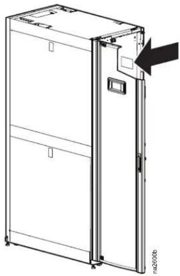
natural_image
Line drawing of a refrigerator with an open door and label 'na2000b' (no text or symbols on the diagram itself)NAMEPLATE
Component Identification
Install kit inventory
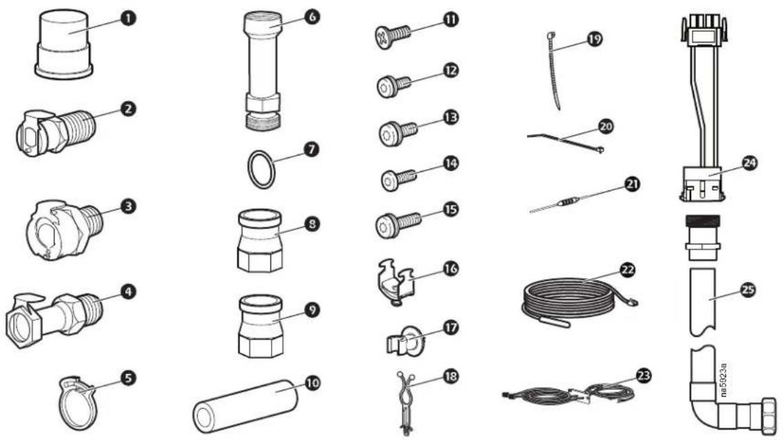
Item Description Qty. Item Description Qty.
① Union end 2
② Humidifier PLC pipe thread, shutoff, 1/4-1 in. NPT*
(ACRC600P and ACRC601P only)
3 Humidifier PLC pipe thread, shutoff, 1/4-in. BSPT** (identified with notches on the hex head portion) (ACRC600P and ACRC602P only)
4 Condensate pump HFC35 pipe thread, 1 shutoff, 3/8-in. BSPT**
⑤ Hose adapter clamp (ACRC60xP only) 2
6 Extension adapter 2
7 Ring seal 4
⑧ Reducer, 3/8-in. to 1/2-in. BSPT** 1
⑨ Reducer, 3/8-in. to 1/2-in. NPT* 1
⑩ Hose adapter (ACRC60xP only) 1
⑪ M5 x 12 mm screw (ACRC60x only) 1
(spare parts)
⑫ M5 x 10-mm TORX ^® screw with washer 5 (spare parts)
M6 x 12-mm TORX screw with washer 5 (spare parts)
14 M6 x 10-mm self-tapping TORX 5 screw (spare parts)
15 M6 x 16-mm TORX screw with washer (spare parts)
16 Strain relief, metal 2 (ACRC602 and ACRC602P only)
17 Wire clip 9
18 Cable tie 10
19 Tie wrap, 200 mm (8 in.) 10
20 Tie wrap – field wiring, 390 mm (15.3 in.)
21 Resistor, 150 Ohm 1
22 Temperature sensor 3
23 Top power cord set 1 (ACRC600 and ACRC602 only)
24 Voltage jumper ***
25 Up-connection adapter 1
*National Pipe Thread
**British Standard Pipe Thread
***Quantity varies depending on model number. See "Voltage selection—ACRC60x units" on page 48 and see "Voltage selection—ACRC60xP units" on page 49
Exterior components
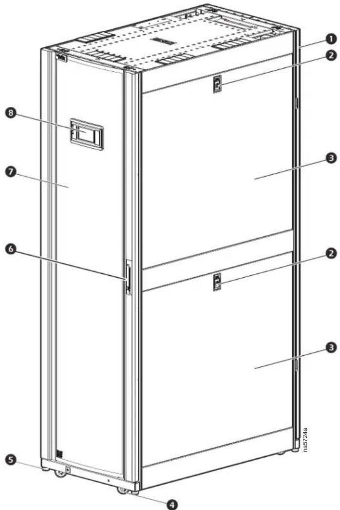
Item Description Item Description
Removable rear doors
② Side panel lock
③ Removable side panel
4 Caster
5 Adjustable leveling foot
6 Door handle and lock
⑦ Removable front door
8 Display interface
Interior components (front)
ACRC60x
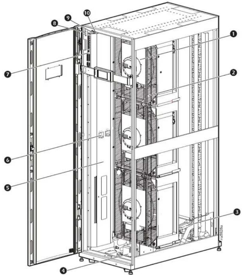
Item Description Item Description
① Fan
② Fan guard
3 Condensate drain pan
4 Condensate pump
5 Electrical panel
6 Main feed breakers
⑦ Customer interface connectors
8 Ground wire
9 Supply air humidity sensor
10 Supply air temperature sensor
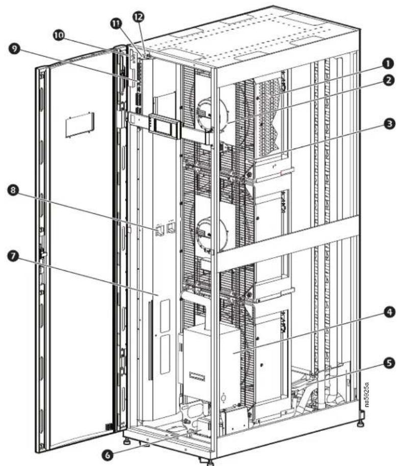
Item Description Item Description
Electrical heater
2 Fan
3 Fan guard
4 Humidifier
5 Condensate drain pan
6 Condensate pump
⑦ Electrical panel
8 Main feed breakers
9 Customer interface connectors
10 Ground wire
⑪ Supply humidity sensor
12 Supply air temperature sensors
Interior components (rear)
ACRC60x—ACRC60xP
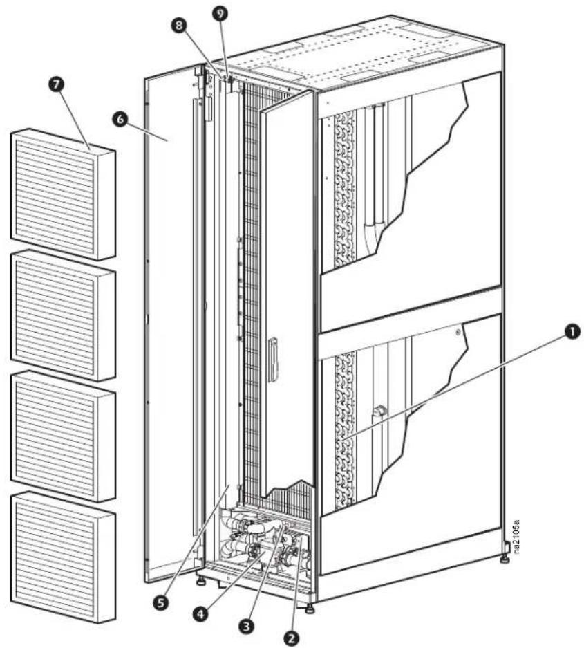
Item Description Item Description
① Chilled water coil
② Chilled water control actuator
③ Chilled water three-way valve body
4 Flow meter
5 Pipe chase
6 Rear doors
7 Air filters
8 Return humidity sensor (ACRC60xP only)
9 Return temperature sensor
Electrical panel
ACRC60x
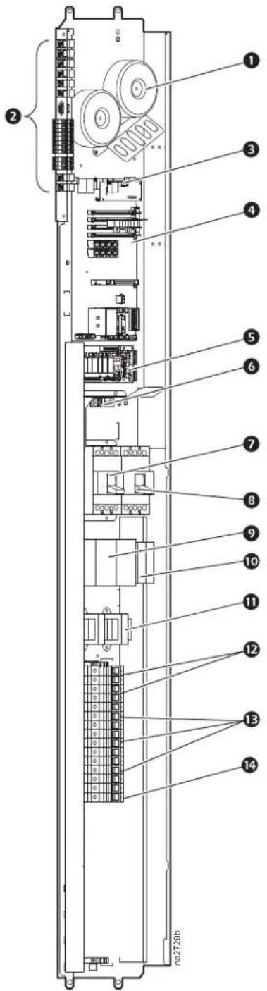
Item Description
1 Transformers
② Customer interface connectors
3 Display interface connection
④ Main controller board
5 Relay board
6 Ground lug
⑦ Main circuit breaker — power feed A
8 Main circuit breaker — power feed B
9 Automatic transfer switch (ATS) contactors
10 ATS timers
⑪ ATS transformer (ACRC601 and ACRC602 only)
⑫ ATS timer circuit breakers
⑬ Fan circuit breakers
14 Controller fuse assembly
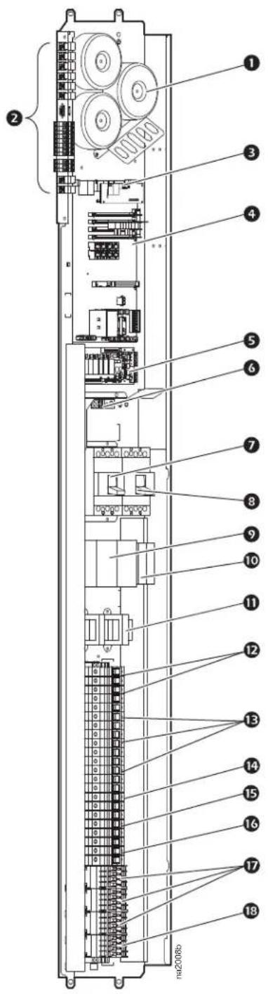
Item Description
1 Transformers
② Customer interface connectors
③ Display interface connection
4 Main controller board
5 Relay board
6 Ground lug
⑦ Main circuit breaker — power feed A
8 Main circuit breaker — power feed B
9 Automatic transfer switch (ATS) contactors
10 ATS timers
⑪ ATS transformer (ACRC601P and ACRC602P only)
12 ATS timer circuit breakers
13 Fan circuit breakers
14 Controller fuse assembly
15 Humidifier circuit breaker
16 Heater circuit breaker
⑰ Heater contactors
18 Humidifier contactor
Main controller board
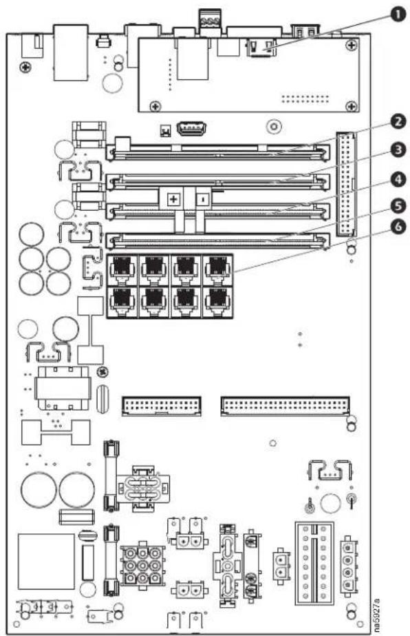
Item Description
① Display interface connection
② R2 SIMM card
3 Differential pressure SIMM
4 Internal RS485 SIMM
⑤ OPTO-isolated input SIMM
6 Temperature sensor connectors
Display interface
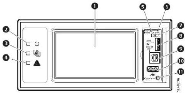
Item Description Function
① LCD display 4.3-in. touch-screen color display.
② Power LED The cooling unit is powered when the LED is illuminated. Unit firmware is updating when LED is blinking.
Check Log LED When this LED is illuminated, a new entry has been made to the event log.
4 Alarm LED Displays current alarm condition of unit.
⑤ Status LED Displays current network management card status.
⑥ Display Reset button Resets the display microprocessor. This has no effect on the air conditioner controller.
7 Link-RX/TX (10/100) LED Displays current network link status.
8 Micro SD card slot Memory card expansion slot.
9 Service port USB-B port used only by service personnel.
10 USB-A port Supports firmware upgrades.
Serial Configuration port Connects the display to a local computer to configure initial network settings or access the command line interface (CLI).
Piping Diagrams
BOTTOM PIPING
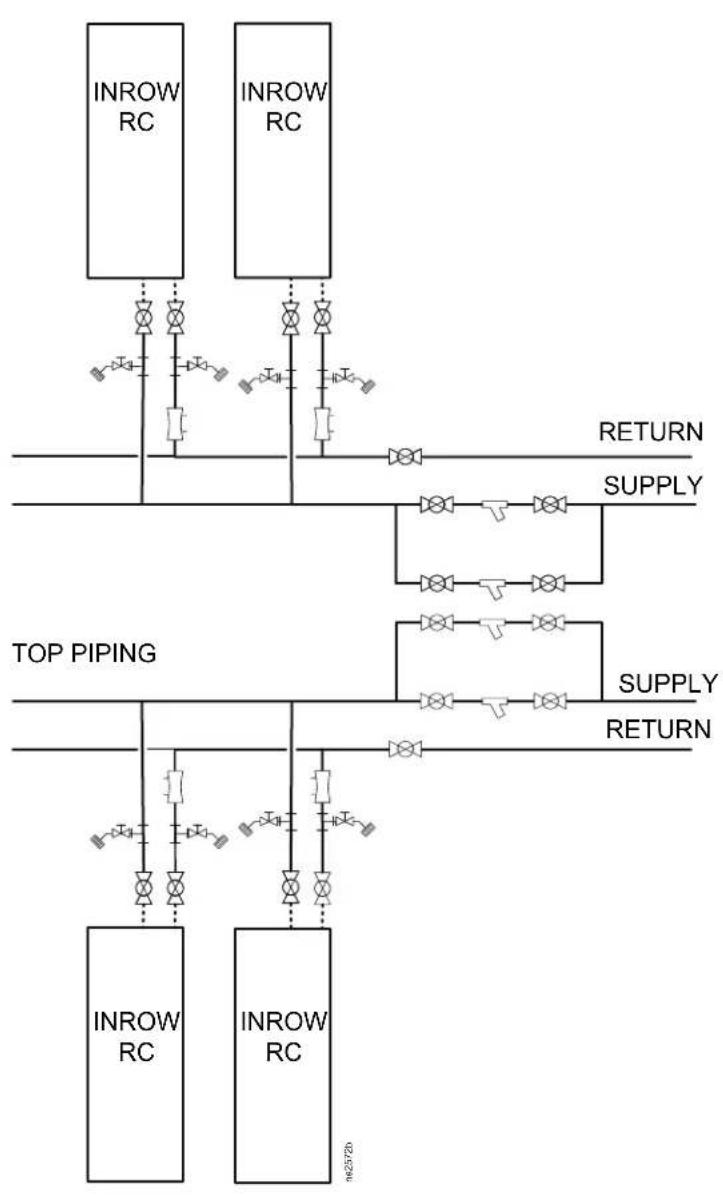
flowchart
graph TD
    subgraph Top_Piping
        A["INROW RC"] --> B["InROW RC"]
        C["INROW RC"] --> D["InROW RC"]
        E["INROW RC"] --> F["INROW RC"]
    end
    subgraph Return
        G["RETURN"] --> H["SUPPLY"]
        I["RETURN"] --> J["SUPPLY"]
        K["RETURN"] --> L["SUPPLY"]
        M["RETURN"] --> N["SUPPLY"]
    end
    style Top_Piping fill:#f9f,stroke:#333
    style Return fill:#ccf,stroke:#333

Flex hose or copper

Copper tubing

Y-strainer with 20 mesh screen (field installed)
NOTE: Blow down may be installed on Y-strainer.

Circuit setter (field installed)
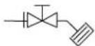
Hose end drain with cap

Isolation valve
NOTE: Top or bottom entry can be drain, humidifier water supply, chilled have the same valves and strainers as
Connections
All connections to and from the equipment can be made through either the top or the bottom of the equipment. All connections are made with quick-disconnect connectors so no soldering, welding, or gluing is necessary. See the following tables for information about the sizes and types of connectors.
Power Connections for Power Feed A and Power Feed B
| Model | Minimum Circuit Ampacity (MCA) | Maximum Overload Protection (MOP) | Full Load Amperes (FLA) | Rated Load Amperes (RLA) |
| ACRC600 11.1 15 -- | ||||
| ACRC601 6.8 15 -- | ||||
| ACRC602* 7.0 15 5.8** 5.8 | ||||
| ACRC600P 50.1 60 -- | ||||
| ACRC601P 24.8 30 -- | ||||
| ACRC602P* -- | 24** | - |
*Consult local and national codes for wire size, conduit requirements, and overload protection. **Local or national codes may require the installation of external disconnects. Two disconnects would be required and must be rated properly for equipment.
| Piping Connection | Type | ACRC600ACRC601ACRC602 | ACRC600P | ACRC601PACRC602P |
| Chilled water supply | Union* | 1 1/2 in. NPSM | 1 1/2 in. NPSM | 1 1/2 in. NPSM |
| Chilled water return | Union* | 1 1/2 in. NPSM | 1 1/2 in. NPSM | 1 1/2 in. NPSM |
| Condensate drain | Quick coupling | 1/2 in. female NPT or BSPT fitting | 1/2 in. female NPT or BSPT fitting | 1/2 in. female NPT or BSPT fitting |
| Humidifier water supply | Quick coupling | 1/4 in. NPT or BSPT | 1/4 in. NPT | 1/4 in. BSPT |
*If the ring seal is damaged, use a new seal (supplied) to prevent leakage. Torque union to 20 Nm (15 lb ft).
| Communication Connections | Type | Minimum Wire Size | Maximum Wire Size | Torque |
| Rack temperature 1 | RJ-45 | - | - | - |
| Rack temperature 2 | RJ-45 | - | - | - |
| Rack temperature 3 | RJ-45 | - | - | - |
| A-Link IN | RJ-45 | - | - | - |
| A-Link OUT | RJ-45 | - | - | - |
| Network port | RJ-45 | - | - | - |
| Customer output, NC-Normally Closed | Screw connector | 0.2 mm^2 (AWG 24) | 0.75 mm^2 (AWG 18) | 0.6 Nm |
| Customer output, COM-Common | Screw connector | 0.2 mm^2 (AWG 24) | 0.75 mm^2 (AWG 18) | 0.6 Nm |
| Customer output, NO-Normally Open | Screw connector | 0.2 mm^2 (AWG 24) | 0.75 mm^2 (AWG 18) | 0.6 Nm |
| Supply GND | Screw connector | 0.2 mm^2 (AWG 24) | 0.75 mm^2 (AWG 18) | 0.6 Nm |
| Supply 12 VDC Screw connector | 0.2 mm | ^2 (AWG 24) | 0.75 mm^2 (AWG 18) | 0.6 Nm |
| Supply 24 VDC Screw connector | 0.2 mm | ^2 (AWG 24) | 0.75 mm^2 (AWG 18) | 0.6 Nm |
| Customer input + | Screw connector | 0.2 mm^2 (AWG 24) | 0.75 mm^2 (AWG 18) | 0.6 Nm |
| Customer input - | Screw connector | 0.2 mm^2 (AWG 24) | 0.75 mm^2 (AWG 18) | 0.6 Nm |
| Modbus D1 | Screw connector | 0.2 mm^2 (AWG 24) | 0.75 mm^2 (AWG 18) | 0.6 Nm |
Communication Connections Type Minimum Wire Size Maximum Wire Size Torque
| Modbus D0 Screw connector 0.2 mm | ^2 (AWG 24) 0.75 mm | ^2 (AWG 18) 0.6 Nm |
| Modbus GND Screw connector 0.2 mm | ^2 (AWG 24) 0.75 mm | ^2 (AWG 18) 0.6 Nm |
| Temperature sensor (front) RJ-45 - - - | ||
| Humidity sensor (front) RJ-45 - - - |
Pre-Installation
Room preparation
During the design of the data center, consider ease of entry for the equipment, floor loading factors, and accessibility to piping and wiring. In addition, the room temperature and humidity combination should conform to the environmental operating envelope as defined in the following graphics.
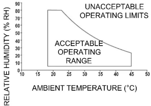
line
| AMBIENT TEMPERATURE (°C) | RELATIVE HUMIDITY (% RH) | | ----------------------- | ------------------------ | | 20 | 80 | | 35 | 40 | | 45 | 20 |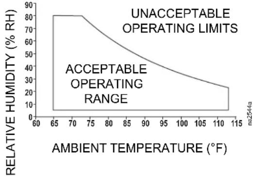
line
| AMBIENT TEMPERATURE (°F) | RELATIVE HUMIDITY (% RH) | | ----------------------- | ------------------------ | | 60 | 80 | | 65 | 80 | | 70 | 80 | | 75 | 70 | | 80 | 60 | | 85 | 50 | | 90 | 40 | | 95 | 30 | | 100 | 25 | | 105 | 20 | | 110 | 15 | | 115 | 10 |Seal the room with a vapor barrier to minimize moisture infiltration. Polyethylene film is recommended for ceiling and wall applications. Apply rubber- or plastic-based paints to concrete walls and floors.
Insulate the room to minimize the influence of exterior heat loads. Reduce fresh air to the minimum required by local and national codes and regulations. Fresh air imposes extreme load variation on the cooling equipment from summer to winter and causes increased system operating costs.
Air distribution
The equipment distributes air in a back-to-front discharge pattern, removing hot air from a hot aisle and discharging cooled air into a cold aisle.
NOTE: The equipment is designed for free air discharge or for use with the Rack Air Containment System or Hot Aisle Containment System. The equipment is not intended to be connected to a duct system.
Incoming power supply requirements

DANGER
HAZARD OF ELECTRIC SHOCK, EXPLOSION, OR ARC FLASH
- Apply appropriate personal protective equipment (PPE) and follow safe electrical work practices. See NFPA 70E or CSA Z462.
- This equipment must be installed and serviced by qualified personnel only.
- Turn off all power supplying this equipment before working on or inside the equipment.
• Always use a properly rated voltage sensing device to confirm power is off. - Replace all devices, doors, and covers before turning on power to this equipment.
Failure to follow these instructions will result in death or serious injury.
Automatic transfer switch (ATS)
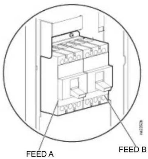
The function of the ATS is to transfer load from feed A to feed B if the power is lost on feed A.
- Feed A (Primary Power Feed) supplies power to all functions in the equipment.
- Feed B (Redundant Power Feed) supplies power to all functions in the equipment.
Dimensions and Weights
Dimensions
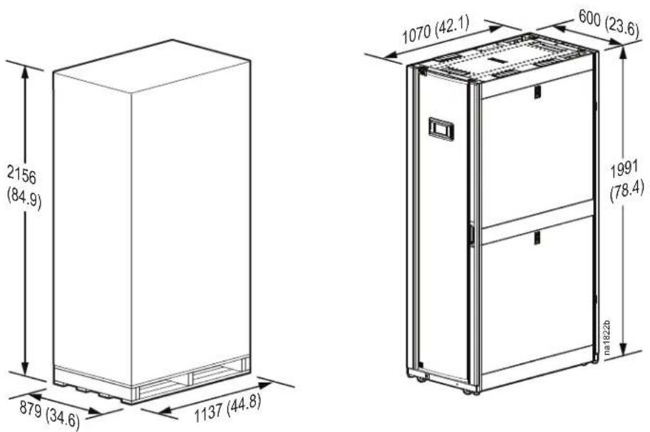
Weights
Model Packed Weight - kg (lb) Unpacked Weight - kg (lb)
ACRC600, ACRC601, ACRC602 405 (892) 345 (760)
ACRC600P, ACRC601P, ACRC602P 412 (907) 352 (776)
Service access
An area of minimum 900 mm (36 in.) of clear floor space in front of and behind the equipment is recommended for service. All required normal maintenance can be performed from the front or back of the equipment. An area of minimum 1200 mm (48 in.) of clear floor space in front of or behind the equipment is recommended to roll the equipment out of a row.
NOTE: Check local and national codes and regulations for further service access requirements.
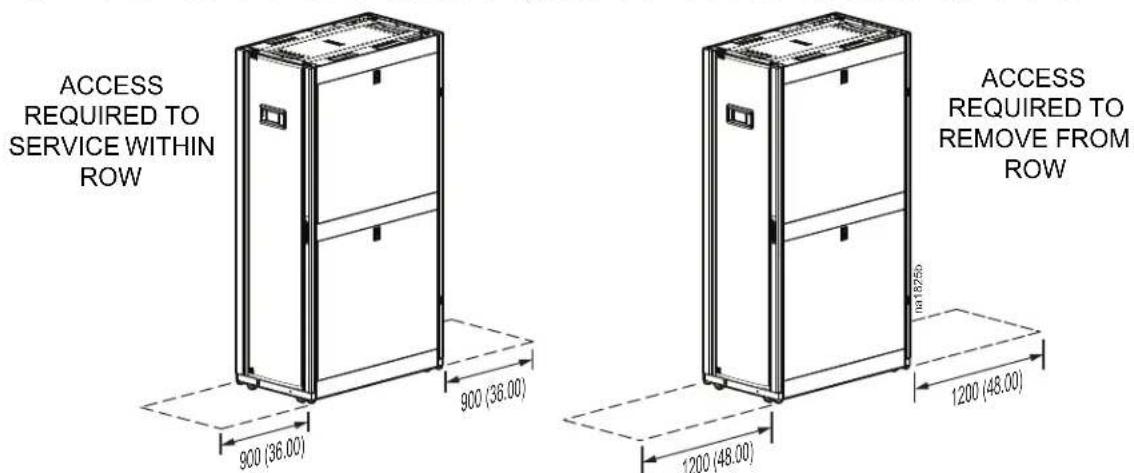
DIMENSIONS ARE SHOWN IN MM (IN.).
Piping and Power Access Locations
Top piping and power access locations (top view)
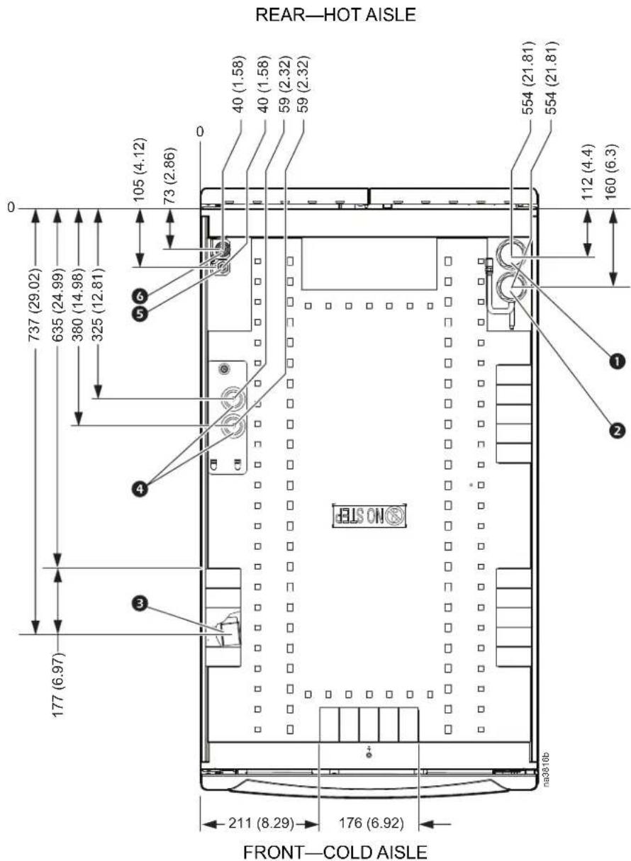
NOTE: Dimensions are shown in mm (in.).
Item Description
① Chilled water inlet
② Chilled water outlet
③ Trough for communication cables
4 Power connections—dual feed
⑤ Humidifier supply (ACRC60xP only)
6 Condensate drain
Bottom piping and power access locations (bottom view)
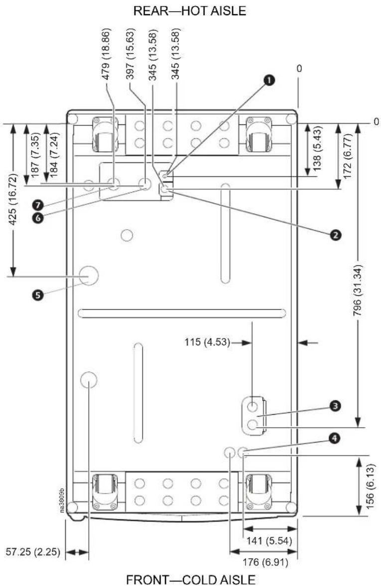
NOTE: Dimensions are shown in mm (in.).
Item Description
① Humidifier supply (ACRC60xP only)
2 Condensate drain
③ Power connections—dual feed
4 Communication connections—27.80 mm (1.09 in.)
5 Condensate overflow
6 Chilled water inlet
7 Chilled water outlet
Removing the Doors and Panels
| ⚠ WARNING |
| MOVING PARTS HAZARD |
| All doors and side panels must be locked during normal operation. Do not open the side panels while the fans are operating. |
| Failure to follow these instructions can result in death, serious injury, or equipment damage. |
| NOTICE |
| EQUIPMENT DAMAGEDo not lean the doors against a wall with the side panel latches facing the wall. This can deform the latches and prevent them from properly working.Failure to follow these instructions can result in equipment damage. |
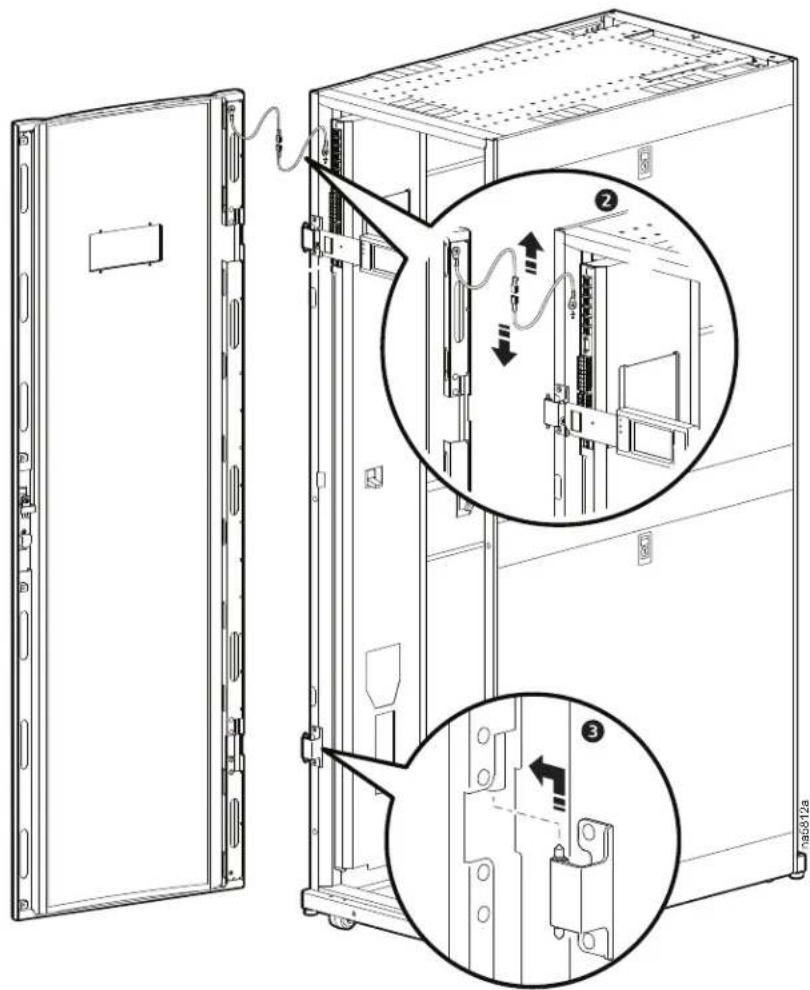
Removing the front door
- Unlock and open the door 90 degrees.
- Unplug the ground wires.
- Lift the door up and off the hinges.
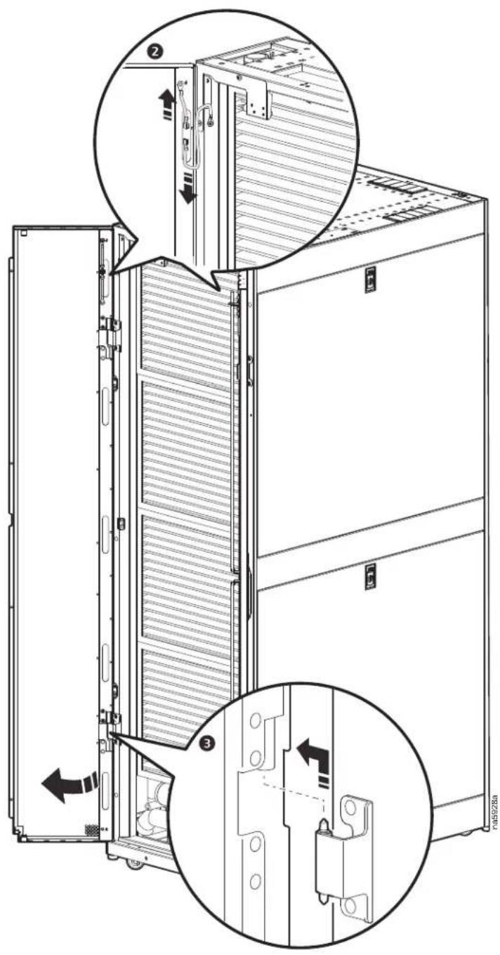
Removing the rear doors
- Unlock and open the doors.
- Unplug the ground wires.
- Lift the door up and off the hinges.
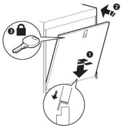
Removing and installing the side panels
REMOVING THE SIDE PANEL
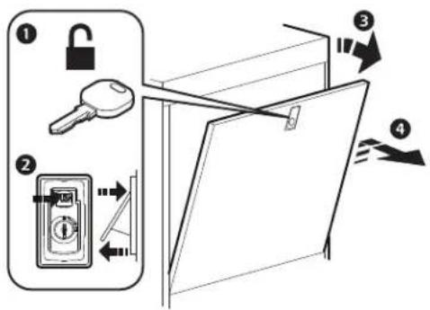
INSTALLING THE SIDE PANEL
na5720b
Removing the electrical panel cover
| ▲ ▲ WARNING |
| ELECTRICAL HAZARD |
| Ensure all wiring is not energized before routing cables into this equipment. Only qualified service and maintenance personnel should work on this equipment. |
| Failure to follow these instructions can result in death, serious injury, or equipment damage. |
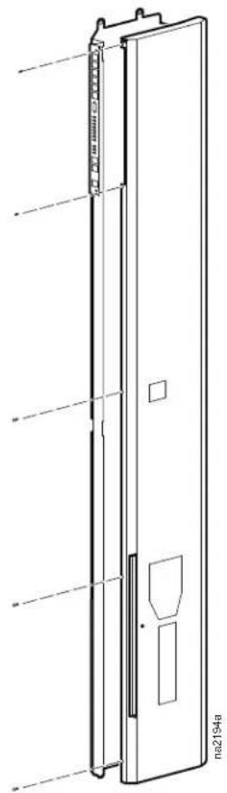
Remove the electrical panel cover to install the main power cable.
- Remove the five M4 screws securing the cover.
- Remove the cover by opening it and sliding it toward the front of the equipment.
natural_image
Technical line drawing of a vertical door or cabinet with mounting holes and internal compartments (no text or symbols)Joining the Equipment to Enclosures
Joining to NetShelter™ SX enclosures
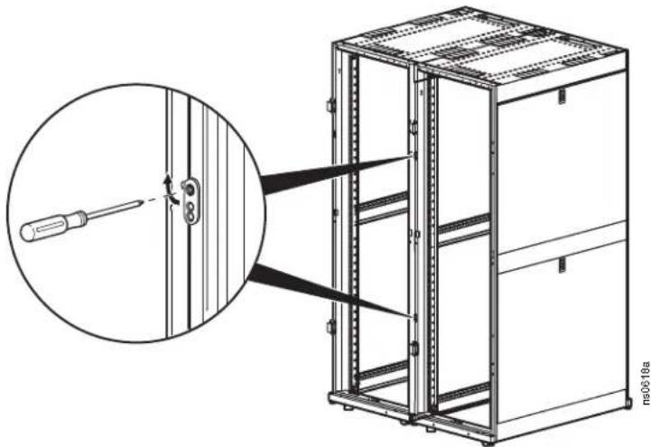
The equipment comes with four joining brackets (two for the front and two for the rear).
-
Remove the front and rear doors. See "Removing the front door" and Removing the rear doors".
-
Locate the four joining brackets. Rotate each bracket ninety degrees toward the adjoining enclosure so the bracket is parallel to the floor and install using the screws provided with the enclosure.
natural_image
Technical line drawing of a server rack cabinet with a screwdriver inserted, showing internal components and mounting bracket (no text or symbols)
For more information, see the Unpacking, Installation, and Customization manual for the NetShelter SX Enclosure.
Joining to NetShelter VX and VS enclosures

For information on joining the equipment to NetShelter VX and VS enclosures, see the installation sheet NetShelter ^™ SX to VX or VS External Joining Kit—AR7601, AR7602.
Leveling the Equipment
| NOTICE |
| WIRING HAZARDAfter re-installing the front door, reconnect all wires previously disconnected.Failure to follow these instructions can result in equipment damage. |
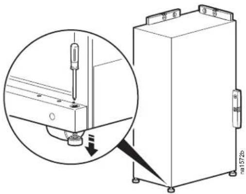
NOTE: The leveling feet at the corners of the equipment provide a stable base if the floor is uneven, but they cannot compensate for a badly sloped surface.
- Remove the front and rear doors.
NOTE: Before removing the front door, unplug the ground wires and any other wire connections that may interfere with the removal of the doors.
- For each leveling foot, insert a Phillips PH2 or standard screwdriver into the screw above the leveling foot. Turn the screw to the right to extend the leveling foot until it makes firm contact with the floor.
NOTE: Use a 13-mm open-ended wrench to level the equipment without removing the doors.
- Re-install the front and rear doors.
natural_image
Technical diagram showing a mechanical assembly with a magnified inset of a screwdriver inserted into a bracket (no text or symbols present)Mechanical Connections
Top water piping
NOTE: The top chilled water supply pipe is supplied with the equipment and must be installed on-site.
NOTE: You may need to remove the top panel from the equipment to gain access to the water connections.
- Remove the air filters.
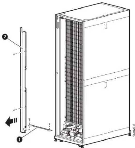
- Loosen the two screws holding the rear condensate drain pan bracket ① and remove the bracket.
- Loosen the two screws holding the air filter bracket located on the left side of the unit and remove the bracket.
- Remove the insulation cap from the union (not shown).
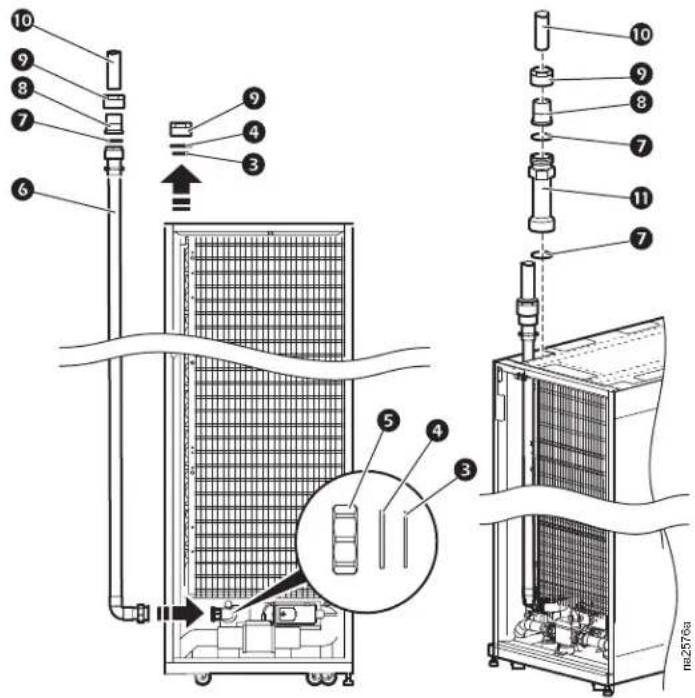
- From both supply and return connections, remove the union nuts ⑤ and save for reuse. Remove and discard the union end blank plates ④ and the gaskets ③.
- Position the insulated chilled water supply pipe ⑥ in the equipment. Mount a new gasket ③ and connect the pipe to the union. Tighten the union to 20 Nm (14.8 ft-lb).
- Insulate the joint with the provided insulation (not shown).
- Connect the water supply pipe 6 to the field-installed pipe 10 using a gasket 7, union end 8, and union nut 9.
- Connect the cold water return fitting to the field-installed pipe 10 using two gaskets 7, union end 8, union nut 9, and extension adapter 11.
- Reinstall air filter bracket ②.
- Reinstall the rear condensate drain pan bracket ① and the air filters.
- Reinstall the top panel, if removed.
Bottom water piping
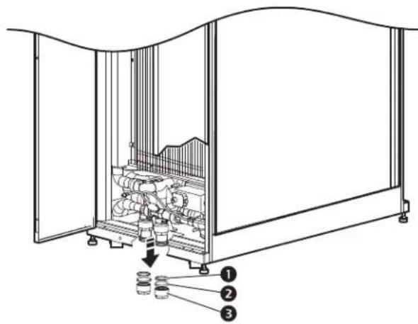
- Remove the insulation cap from the union ① (not shown).
- Remove the union nut ③, and save it for reuse. Remove and discard the union end blank plate ②, and the ring seal ①.
NOTE: New items are provided with the equipment.
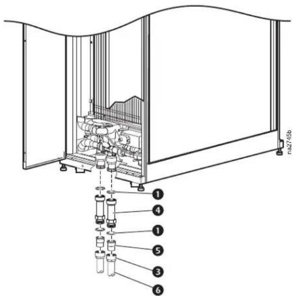
- Install the union nuts ③ to field-supplied tubing ⑥.
- Install new ring seals ①, extension adapters ④, and insertion adapters ⑤, as shown. Connect the pipe to the union. Tighten the union to 20 Nm (14.8 ft-lb).
Humidifier (ACRC60xP units only)
The humidifier water supply line is routed to the unit in flexible tubing (or alternative tubing approved by local building codes) that will allow the humidifier water supply line connector to be moved approximately 25 mm (1 in.) away from the equipment. This facilitates removing the equipment from a row.
A factory-installed quick-connector for connecting the tubing to the equipment is supplied. The quick connector has a male 1/4-in. NPT or male 1/4-in. BSPT to connect to a compression fitting. The quick-connector has a shut-off function, so no separate shut-off valve is necessary.
natural_image
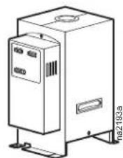
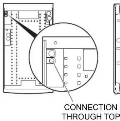
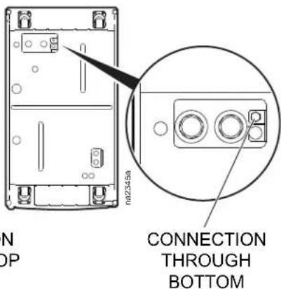
Line drawing of a rectangular industrial machine with control panel and mounting base (no text or symbols)The humidifier water supply line can be connected through either the top or the bottom of the equipment as shown. Male quick-connectors are positioned in both the top and the bottom of the equipment.
Water pressure should be between 100 and 800 kPa (15 and 115 psi) for proper humidifier operation. Dirty water must be filtered before it is supplied to the humidifier. Water temperature must be between 1°C and 40°C (34°F and 104°F). Do not use softened, de-mineralized, or de-ionized water.

See the manual included with the humidifier for more information about water quality, mineral content, hardness, and minimum/maximum levels for conductivity.
NOTE: Before making any connections, clear any debris that may have accumulated during assembly from the humidifier water supply line.
NOTE: It is recommended that a solenoid water valve be installed in the humidifier supply line, connected to a leak detector.
NOTE: Perform all piping in accordance with applicable industry guidelines as well as local and national codes and regulations.
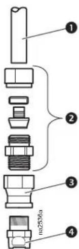
Connect the fittings to the humidifier water supply line as shown, then connect the water supply line quick-connector to the top or bottom humidifier input.
Item Description
1 Flexible tubing (field supplied and installed)
2 Compression fitting (field supplied and installed)
3 Straight reduction (supplied)
4 Quick-connector (supplied)
Condensate overflow
NOTICE
WATER DAMAGE
Failing to perform the following procedure may result in condensate pan overflow and possible damage to the data center.
Failure to follow these instructions can result in equipment damage.
Connect the equipment condensate overflow line to an external drain using the fittings, as shown.
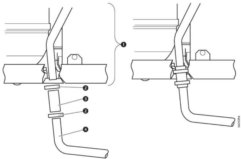
Item Description
① InRow RC
② Hose adapter clamp (supplied)
③ Hose adapter (supplied)
4 7/8-in. copper tubing (field supplied and installed)
Leak sensor (optional)
Install up to four leak sensors (AP9326) in series, as needed.
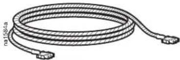
natural_image
Coiled cable with connectors, no visible text or symbols- Connect the leak sensor to the equipment using the plug located as shown.
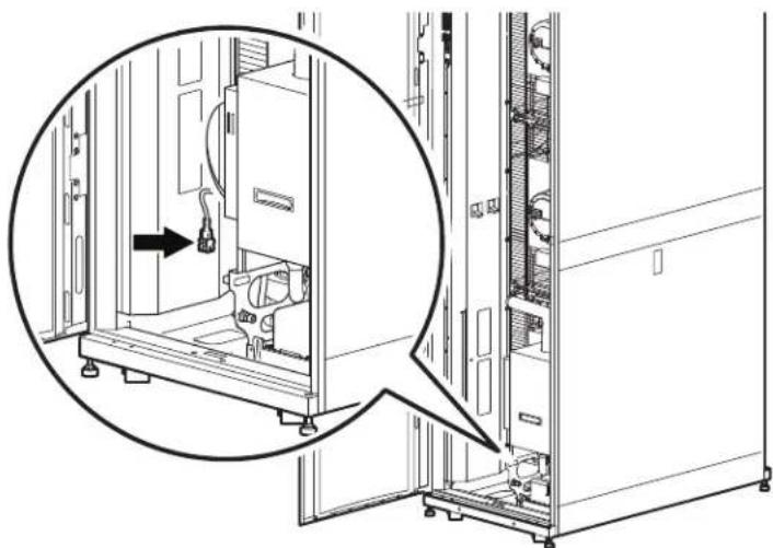
natural_image
Technical line drawing of a server rack with an inset close-up showing internal components (no text or symbols)ACRC60xP UNITS ACRC60x UNITS
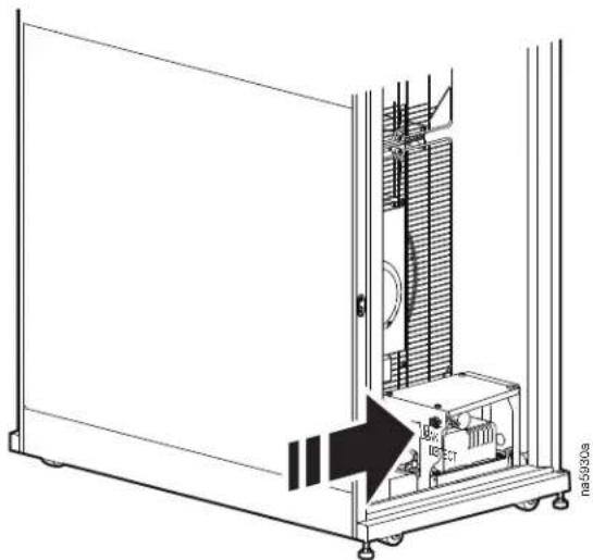
natural_image
Technical line drawing of a mechanical device with internal components and an arrow indicating direction (no text or symbols)- Position the leak sensor inside or outside the equipment.
NOTE: Install leak sensors on a clean surface, and do not allow them to touch metal that is in an air stream.
-
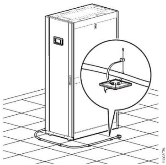
Route the leak sensor to the outside of the equipment through the hole provided in the base.
-
Secure the leak sensor wire to surfaces using cable ties and cable tie holders (provided with the leak detector).
natural_image
Technical line drawing of a rectangular enclosure with a magnified inset showing a mechanical component (no text or symbols)Filling and Purging the Unit
When the unit has been properly piped, begin the filling process (top piping configuration shown).
WARNING
ELECTRICAL SHOCK HAZARD
Ensure that all electrical connections are unplugged before you introduce water into the unit.
Failure to follow these instructions can result in death, serious injury, or equipment damage.
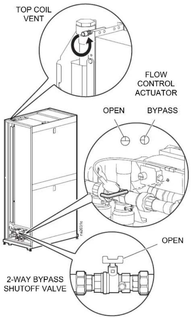
- Open the 2-way bypass shutoff valve by turning the handle 90° to the right. Using a 2.5-mm hex key, turn the flow control actuator to the fully open position.
- Remove the cap from the top coil vent and push the vent.
- At the water supply, open the appropriate valves to begin letting water slowly into the unit.
- Stop pushing the top coil vent when water begins slowly flowing out of the vent.
- At the water supply:
a. Open all valves no greater than 113 l/m (30 GPM), and allow the water supply to reach the highest possible flow to the unit for 45 seconds.
b. Close the valves to a 3.8–11.4 l/m (1–3 GPM) flow for 60 seconds.
c. Open the valves to maximum flow for another 45 seconds.
d. Balance the system to provide the designed flow rate to all equipment.
Chiller
Three types of chillers can be connected to the unit:
- Schneider Electric size-matched chiller/thermal storage system
• Building chilled water system
• Existing dedicated chiller
Cooling unit requirements
| Entering water temperature 7.2–12.8°C (45–55°F) | |
| Weight of unit fully flooded with chilled water (ACRC60x units) 363 kg (800 lb) | |
| Weight of unit fully flooded with chilled water (ACRC60xP units) 370 kg (816 lb) | |
| Flow rate 1.2–2.5 l/s (19.0–39.6 GPM) | |

See the chiller Installation Manual, and Operation and Maintenance Manual for proper installation procedures.
Electrical Connections
⚠️ ⚠️ DANGER
HAZARD OF ELECTRIC SHOCK, EXPLOSION, OR ARC FLASH
- Potentially dangerous and lethal voltages exist within this equipment. More than one disconnect switch may be required to energize or de-energize this equipment. Observe all cautions and warnings. Failure to do so could result in serious injury or death. Only qualified service and maintenance personnel may work on this equipment.
- Three-phase electrical service is required. Electrical service must conform to local and national electrical codes and regulations. The equipment must be grounded. Check the equipment nameplate for correct ratings.
- Use a voltmeter to ensure that power is turned off before making any electrical connections.
Failure to follow these instructions will result in death or serious injury.
The following electrical connections are required in the field:
- Controls (customer interface connections, Network Management Card)
- Communication (A-Link, Building Management System)
- Power to the InRow RC cooling unit (3-phase plus ground)
All electrical connections must be in accordance with applicable industry guidelines as well as local and national codes and regulations.
See the equipment nameplate for voltage and current requirements.
Make all low-voltage connections, including data and control connections, with properly insulated wires. Insulation of low-voltage wiring must be rated for at least the voltage of any adjacent wiring.
Customer interface connections
NOTE: Wire all input and output connections as Class 2 circuits.
Depending on the configuration, additional customer interface connections may be required for the A-Link remote communications through the Network Management Card support or traditional equipment-monitoring software.

Item Description
1 Rack inlet temperature sensors 1, 2, 3
② A-Link IN
③ A-Link OUT
4 Network port
⑤ Customer output, NC (normally closed)
6 Customer output, COM (common)
⑦ Customer output, NO (normally open)
8 Supply GND (Ground)
9 Supply 12 Vdc (current limit: 20 mA)
10 Supply 24 Vdc (current limit: 20 mA)
⑪ Customer input + (12–30 Vac/Vdc, 24 Vdc @ 11 mA)
12 Supply COM
13 Modbus D1
14 Modbus D0
15 Modbus GND
16 Supply air temperature sensor (front)
⑰ Supply air humidity sensor (front)
NOTE: For a top installation, route control wiring through the wire channel located at the top left hand corner just above the customer interface connectors.
For a bottom installation, route the control wiring to the customer access hole in the bottom of the equipment through wire clamps from the interface connectors. Then, route the wiring down along the electrical panel and secure with wire clamps.
Description of customer interface connectors
| Item | Description Function | |
| 1 | Rack temperature sensors 1, 2, 3 | Three temperature sensors, which must be installed on the cold aisle side of the server racks. See “Rack temperature sensors” on page 41. |
| 2 | A-Link IN | In and out connections for A-Link. The terminators supplied with the equipment must be plugged into the first A-link port and the final A-Link port for the system. |
| 3 | A-Link OUT | |
| 4 | Network port | 10/100 Base-T Network port. Connects the equipment to the network; Status and Link LEDs indicate network traffic.Status LED—blinks orange and green at startup; indicates the status of the network connection (solid green—IP address established; blinking green—attempting to obtain an IP address).Link LED—blinks to indicate network traffic (green—operating at 10 mbps; orange—operating at 100 mbps). |
| 5 | Customer output, Normally Closed (NC) | Customer-configurable output relay which can be activated for all types of alarms or critical alarms. The relay can be connected to external equipment using 30 Vac/dc, 2 A. |
| 6 | Customer output, Common (COM) | |
| 7 | Customer output, Normally Open (NO) | |
| 8 | Supply GND Can be used for customer input and output interface. | |
| 9 | Supply 12 Vdc | Can be used for customer input and output interface. Current limit is 20 mA. |
| 10 | Supply 24 Vdc | Can be used for customer input and output interface. Current limit is 20 mA. |
| 11 | Remote shutdown+ | Used for remote shutdown of the InRow RC. Voltage is applied from the internal power supply or by using an external power supply. |
| 12 | Remote shutdown- Ground connection point for remote shutdown supply source. | |
| 13 | Modbus D1 (RXTX+) | Connections for Building Management System. Wire a 150 Ohm terminator resistor (supplied) into the final InRow RP, between Modbus D0 and Modbus D1. |
| 14 | Modbus D0 (RXTX-) | |
| 15 | Modbus GND | |
| 16 | Supply air temperature sensor (front) Temperature sensor installed on the front of the equipment. | |
| 17 | Supply air humidity sensor (front) Humidity sensor installed on the front of the equipment. | |
Rack temperature sensors
The rack temperature sensors control the equipment airflow and ensure adequate supply of cooling air to the server racks in the data center.
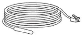
The equipment is supplied with three external rack temperature sensors. See “Install kit inventory” on page 10. These sensors, along with cable ties and wire clips, are included in the installation kit shipped with the equipment.
How to install the rack temperature sensors
- Insert the rack temperature sensor connector in the temperature sensor port customer interface connections. See “Customer interface connections” on page 39.
a. For a top installation, push the rack temperature sensor through the wire channel located at the top of the equipment in the left hand side just above the customer interface connectors.
b. For a bottom installation, route the sensor through the wire clamps along the electrical panel and then push the sensor through the customer access hole in the bottom of the equipment.
- Route the sensor through either the top or the bottom of the adjacent server rack.
- Secure the temperature sensor cable to the front door of the adjacent server rack at multiple locations using the provided wire clips as shown. See "Install kit inventory" on page 10.
NOTE: Remote rack temperature sensors must be installed for proper operation.
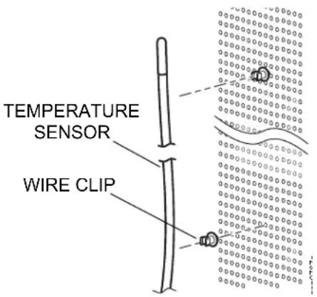
The sensors should be located on racks that are adjacent to the cooling unit. The optimum position of the rack temperature sensors will vary from installation to installation but should be located in close proximity to fan-cooled IT equipment to ensure accurate readings.
Servers most likely to have insufficient or inadequately cooled air due to the recirculation of hot air from the hot aisle include the following:
a. Servers positioned at the top of a rack
b. Servers positioned at any height in the last rack at an open end of a row
c. Servers positioned behind flow-impairing obstacles such as building elements
d. Servers positioned in a bank of high-density racks
e. Servers positioned next to racks with Air Removal Units (ARU)
f. Servers positioned very far from the equipment
g. Servers positioned very close to the equipment
Water outlet temperature sensors
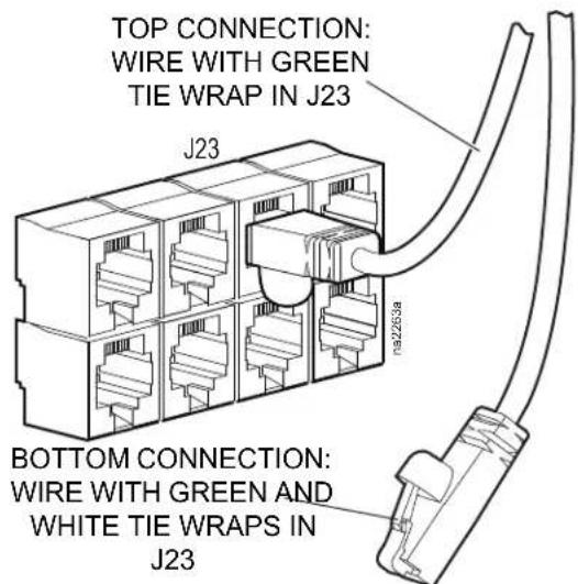
There are two water outlet temperature sensors, one for top connection and one for bottom connection. These sensors are wired to the main board on the electrical panel.
The unit is delivered with top connection as the default configuration, i.e., the wire with a green tie wrap is positioned in connector J23 (marked with green) on the main board. If the configuration is changed from top to bottom, switch the wire already positioned in the connector J23 with the wire labeled with a green and a white tie wrap. This wire is part of the wire harness inside the electrical panel.
Communication connections
A-Link connections: The A-Link bus connection allows communication between cooling units. Only one InRow RC unit needs to be defined through the display. The numbering of the other InRow RC units (up to a maximum of twelve) will take place automatically.
To enable the equipment to work as a group, link the units using the supplied cables or CAT-5 cables with RJ-45 connectors as shown. Terminators (120 Ohm, 1/4 W) must be inserted into the open A-Link ports at the first and last InRow RC unit.
The maximum wire length for the entire group may not exceed 1000 m (3,280 ft).
FIRST INROW RC SECOND INROW RC LAST INROW RC
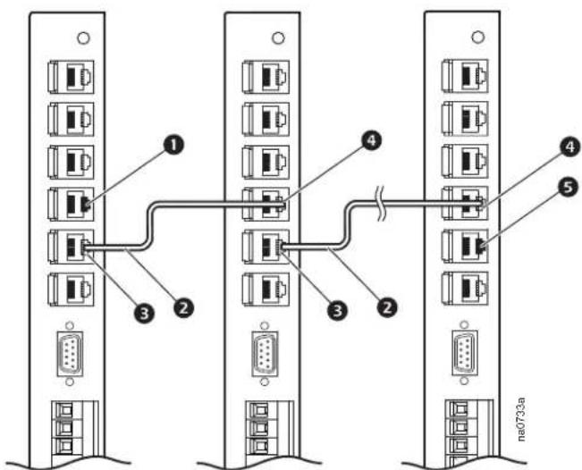
Item Description Item Description
① A-Link in (with provided RJ-45 terminator)
② InRow A-Link cable (CAT-5 Ethernet cable)
3 A-Link out
4 A-Link in
5 A-Link out (with provided RJ-45 terminator)
Building Management System (BMS): The Modbus interface allows each cooling unit to communicate with the BMS. Use a three-wire cable to connect each cooling unit in turn. Wire a terminator resistor (150 Ohm, 1/4 W) into the Modbus master and the final cooling unit between Modbus D0 and Modbus D1. This terminator is included in the installation kit (see “Install kit inventory” on page 10).
Each cooling unit has a three-wire Modbus terminal on the display interface. A connector with screw terminals is used to attach wiring. See "Customer interface connections" on page 39 for specific layout of the customer interface.

For information on setup of Modbus parameters, see the InRow RC Operation and Maintenance Manual.
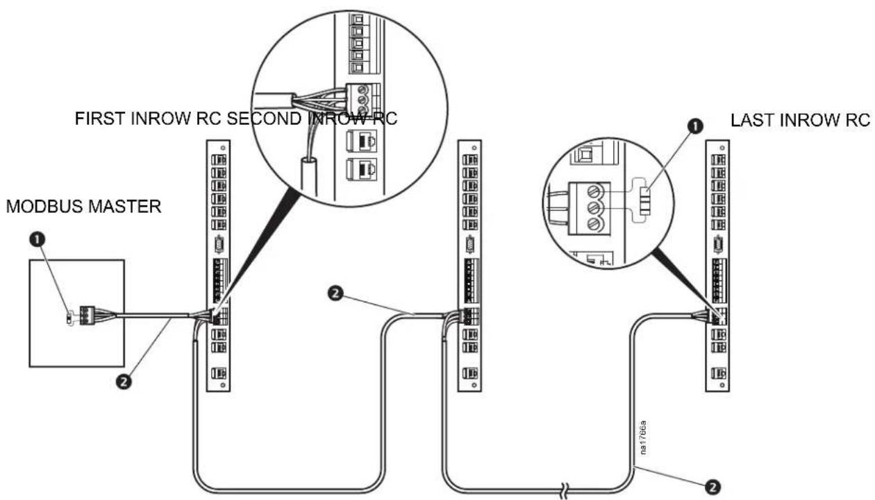
Item Description
① Termination resistor (provided)
② Modbus cable (RS-485)
Network port
The network port allows communication from the InRow RC unit to the network.
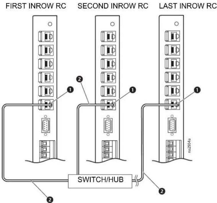
Item Description
① Network port
② LAN cable (10/100 Base-T)
Power Connections
| WARNING |
| ELECTRICAL HAZARDElectrical service must conform to local and national electrical codes and regulations.The equipment must be grounded.Failure to follow these instructions can result in death, serious injury, or equipment damage. |
| ▲WARNING |
| HAZARD TO EQUIPMENT OR PERSONNEL |
| All work must be performed by Schneider Electric qualified personnel. |
| Failure to follow these instructions can result in death, serious injury, or equipment damage. |
Wiring configurations
Route incoming power from the PDU to the electrical panel located in the left side of the equipment. Power can be routed either through the top or the bottom. For ACRC600 and ACRC602 units, incoming power may be supplied to the equipment using the supplied power cords through the top only.
Install power cords (ACRC600 and ACRC602 only)
NOTICE
POWER SUPPLY CONNECTION
Only qualified personnel may connect the equipment to utility power using direct wiring. All wiring must be done in compliance with local and national codes.
Failure to follow these instructions can result in equipment damage.
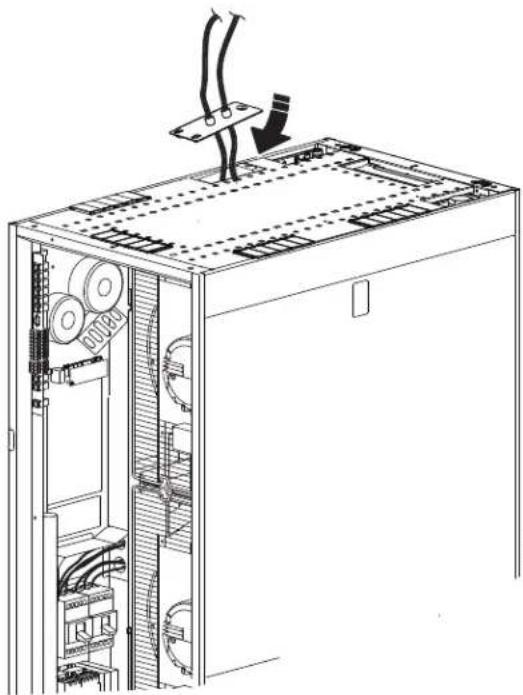
- Remove the factory-installed knockout plate from the top of the equipment. See "Top piping and power access locations (top view)" on page 24. Save the screw for later use.
- Remove the electrical panel cover. See "Removing the electrical panel cover" on page 29.
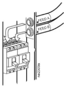
- Observe the markings on the two power cords. Insert feed A in the conduit closest to the front of the equipment, and feed B in the conduit closest to the rear of the equipment.
- Connect the L1, L2, and L3 leads of feed A and feed B to the two circuit breakers per the label above the breakers. Torque the screws per the torque values marked on the breakers. Connect the grounds to the terminal above the circuit breakers.
- Secure the connection plate to the top panel of the equipment using the screw you removed earlier.
- Reinstall the electrical panel cover.
natural_image
Technical line drawing of an internal server rack with cable routing and a downward arrow indicating motion (no text or symbols)Top routing
- Remove the electrical panel cover. See "Removing the electrical panel cover" on page 29.
- Remove the factory-installed knockout plate from the top of the equipment. See "Top piping and power access locations (top view)" on page 24. Save the screw for later use.
- Enlarge the two pilot holes in the knockout plate as needed to accept conduit connectors.
- Attach the conduit connectors to the knockout plate.
- Secure the knockout plate to the top of the equipment.
- Route power cabling to the main breakers as shown.
- Connect feed A and B power wiring to the tops of the two main circuit breakers using the torque specified on the breakers. Connect the phases of the two power feeds as marked next to the terminals.
- Connect the ground wires to the ground terminal block located above the main circuit breakers.
- Reinstall the connection plate and the electrical panel cover.
Bottom routing
- Locate the supplied knockout plate.
- Install the knockout plate on the top of the equipment where you removed the power connection plate and power cords.
- Locate the power connection plate in the bottom of the unit. See "Bottom piping and power access locations (bottom view)" on page 25.
- Loosen the screw securing the connection plate, and remove the plate.
- Enlarge the two pilot holes in the connection plate as needed to accept conduit connectors.
- Attach the conduit connectors to the connection plate. Secure the connection plate to the bottom of the equipment.
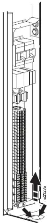
- Route the cabling to the main breakers as shown.
- Fasten the cabling inside the unit with the provided tie wraps.
- Connect feed A and feed B power wiring to the tops of the two main circuit breakers using the torque specified on the breakers. Connect the phases of the two power feeds as marked next to the terminals.
- Connect the ground wires to the ground terminal block located just above the main circuit breakers.
- Reinstall the connection plate and the electrical panel cover.
Strain relief (ACRC602 and ACRC602P only)
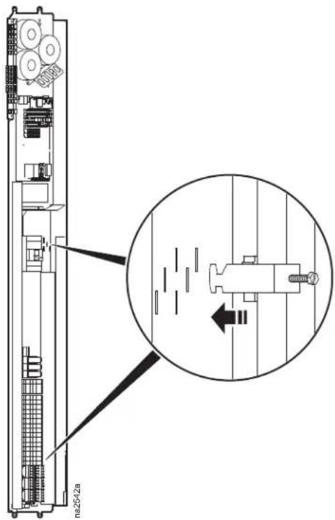
- Hook one strain relief into a pair of slots in each of the two locations shown. See "Install kit inventory" on page 10.
- Route the electrical cable up from the bottom of the equipment, passing through each strain relief.
- Tighten the screw on each strain relief to capture the electrical cable, taking the weight off of the inner conductors.
- Continue connecting electrical wiring to the circuit breaker.
Voltage selection—ACRC60x units
Your equipment can operate at various supply voltages, provided the proper voltage jumpers are connected to the input transformers. Read the part number on the jumpers connected at the factory and compare that number to the table below. If the correct jumpers for your input voltage are not connected, remove them and connect the proper jumper.
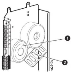
Jumper Connections
① Transformer A connected to J50 (②)
| SKU Input Voltage Use Jumper Part Number | ||
| ACRC600 | 208 (50/60 Hz) 0W2540 (default) | |
| 230 (50/60 Hz) 0W2541 | ||
| ACRC601 | 460 (60 Hz) 0W2545 | |
| 480 (60 Hz) 0W2546 (default) | ||
| ACRC602 | 380 (50/60 Hz) 0W2542 | |
| 400 (50/60 Hz) 0W2543 (default) | ||
| 415 (50/60 Hz) 0W2544 | ||
Voltage selection—ACRC60xP units
Your equipment can operate at various supply voltages, provided the proper voltage jumpers are connected to the input transformers. Read the part number on the jumpers connected at the factory and compare that number to the table below. If the correct jumpers for your input voltage are not connected, remove them and connect the proper jumper.
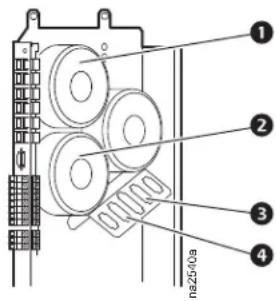
Jumper Connections
① Transformer B connected to J51 (③)
② Transformer A connected to J50 (④)
| SKU Input Voltage Use Jumper | Part Number | |
| ACRC600P | 208 (50/60 Hz) 0W2540 (default) | |
| 230 (50/60 Hz) 0W2541 | ||
| ACRC601P | 460 (60 Hz) 0W2545 | |
| 480 (60 Hz) 0W2546 (default) | ||
| ACRC602P | 380 (50/60 Hz) 0W2542 | |
| 400 (50/60 Hz) 0W2543 (default) | ||
| 415 (50/60 Hz) 0W2544 | ||
Worldwide Customer Support
Customer support for this or any other product is available at no charge in any of the following ways:
- Visit the Schneider Electric Web site to access documents in the Schneider Electric Knowledge Base and to submit customer support requests.
- www.schneider-electric.com (Corporate Headquarters)
Connect to localized Schneider Electric Web sites for specific countries, each of which provides customer support information.
- www.schneider-electric.com/support/
Global support searching Schneider Electric Knowledge Base and using e-support.
- Contact the Schneider Electric Customer Support Center by telephone or e-mail.
- Local, country-specific centers: go to www.schneider-electric.com > Support > Operations around the world for contact information.
For information on how to obtain local customer support, contact the representative or other distributors from whom you purchased your product.
As standards, specifications, and designs change from time to time, please ask for confirmation of the information given in this publication. All trademarks owned by Schneider Electric Industries SAS or its affiliated companies.
- Schneider Electric IT Corporation Legal Disclaimer
- Table of Contents
- Safety....5
- General Information......8
- Installation....26
- Important Safety Information
- DANGER
- WARNING
- CAUTION
- NOTICE
- Safety Notices During Installation
- HAZARD OF ELECTRIC SHOCK, EXPLOSION, OR ARC FLASH
- HAZARD OF EQUIPMENT FALLING OVER
- HAZARD FROM MOVING PARTS
- UNPROTECTED OUTPUTS
- Inspecting the Equipment
- Storing the Equipment Before Installation
- Moving the Equipment
- Moving the equipment to its final location
- Waste Disposal
- Waste Electrical and Electronic Equipment (WEEE) disposal
- Model Identification
- Component Identification
- Exterior components
- Item Description Item Description
- Interior components (front)
- Interior components (rear)
- Electrical panel
- ACRC60x
- Item Description
- Main controller board
- Display interface
- Item Description Function
- Piping Diagrams
- Connections
- Pre-Installation
- Room preparation
- Air distribution
- Incoming power supply requirements
- Automatic transfer switch (ATS)
- Dimensions and Weights
- Weights
- Service access
- Piping and Power Access Locations
- Bottom piping and power access locations (bottom view)
- Removing the Doors and Panels
- Removing the front door
- Removing the rear doors
- Removing and installing the side panels
- Removing the electrical panel cover
- Joining the Equipment to Enclosures
- Joining to NetShelter™ SX enclosures
- Joining to NetShelter VX and VS enclosures
- Leveling the Equipment
- Mechanical Connections
- Top water piping
- Bottom water piping
- Humidifier (ACRC60xP units only)
- Condensate overflow
- WATER DAMAGE
- Leak sensor (optional)
- Filling and Purging the Unit
- ELECTRICAL SHOCK HAZARD
- Chiller
- Electrical Connections
- ⚠️ ⚠️ DANGER
- Customer interface connections
- Rack temperature sensors
- How to install the rack temperature sensors
- Water outlet temperature sensors
- Communication connections
- Network port
- Power Connections
- Wiring configurations
- Install power cords (ACRC600 and ACRC602 only)
- POWER SUPPLY CONNECTION
- Top routing
- Bottom routing
- Strain relief (ACRC602 and ACRC602P only)
- Voltage selection—ACRC60x units
- Jumper Connections
- Voltage selection—ACRC60xP units
- Worldwide Customer Support
Brand : APC
Model : ACRC600P
Category : Computer Cooling Component