
ACRD301 - Computer Cooling Component APC - Free user manual and instructions
Find the device manual for free ACRD301 APC in PDF.


| Product Type | Precision Cooling Unit for Data Centers |
| Model | APC ACRD301 |
| Cooling Capacity | 30 kW (sensible) |
| Airflow | Up to 5,000 m³/h |
| Refrigerant | R410A |
| Dimensions (W x D x H) | 600 mm x 1070 mm x 2000 mm |
| Weight | 285 kg |
| Power Supply | 400 V, 3-phase, 50/60 Hz |
| Maximum Power Consumption | 10 kW |
| Operating Temperature Range | -5°C to 45°C |
| Noise Level | < 65 dB(A) at 1 m |
| Communication | Ethernet, Modbus, SNMP |
| Air Filtration | Replaceable EU4 filter |
| Condensate Management | Internal pump with drain hose |
| Safety Certifications | CE, UL, RoHS |
| Warranty | 1 year on-site |
Frequently Asked Questions - ACRD301 APC
User questions about ACRD301 APC
0 question about this device. Answer the ones you know or ask your own.
Ask a new question about this device
Download the instructions for your Computer Cooling Component in PDF format for free! Find your manual ACRD301 - APC and take your electronic device back in hand. On this page are published all the documents necessary for the use of your device. ACRD301 by APC.
USER MANUAL ACRD301 APC
InRow® Direct Expansion Air Conditioners
ACRD301 and ACRH301 Series
Management Information Base
990-5988C-001
Release Date: 01/2024
natural_image
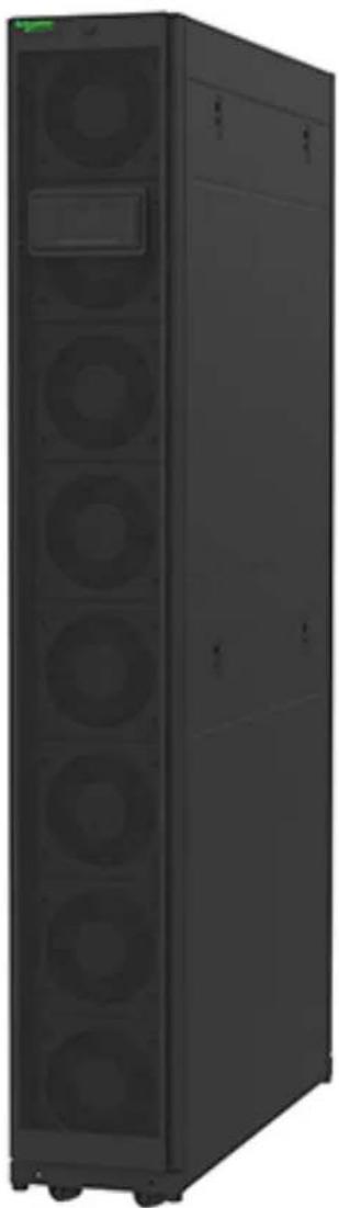
Exterior view of a black server rack unit with multiple circular fans and a central display (no visible text or labels)Legal Information
The Schneider Electric brand and any trademarks of Schneider Electric SE and its subsidiaries referred to in this guide are the property of Schneider Electric SE or its subsidiaries. All other brands may be trademarks of their respective owners.
This guide and its content are protected under applicable copyright laws and furnished for informational use only. No part of this guide may be reproduced or transmitted in any form or by any means (electronic, mechanical, photocopying, recording, or otherwise), for any purpose, without the prior written permission of Schneider Electric.
Schneider Electric does not grant any right or license for commercial use of the guide or its content, except for a non-exclusive and personal license to consult it on an "as is" basis. Schneider Electric products and equipment should be installed, operated, serviced, and maintained only by qualified personnel.
As standards, specifications, and designs change from time to time, information contained in this guide may be subject to change without notice.
To the extent permitted by applicable law, no responsibility or liability is assumed by Schneider Electric and its subsidiaries for any errors or omissions in the informational content of this material or consequences arising out of or resulting from the use of the information contained herein.
Table of Contents
Cooling MIB Overview....5
Self-Describing....5
General Organization ....5
MIB Data Tables....8
coolingUnitAboutTable 8
coolingUnitStatusAnalogTable 9
coolingUnitStatusDiscreteTable 13
coolingUnitConfigurationAnalogTable....14
coolingUnitConfigurationDiscreteTable....17
coolingUnitConfigurationStringTable 19
coolingUnitExtendedAnalogTable 20
coolingUnitExtendedDiscreteTable 23
coolingUnitExtendedStringTable 25
Cooling MIB Overview
The information in this document is compatible with display firmware for the InRow® DX ACRD3001 and ACRH301 Series of cooling units
Self-Describing
The Cooling MIB is self-describing in that only the general format of the information is described by the MIB. The actual application data is described by the data in the OIDs themselves. The user must walk the MIB to get information about the data that is available.
General Organization
- OID Types
- Analog: Data that has a continuous range of numeric values. Examples:
- Temperature
- Humidity
- Cool setpoint
- Discrete: Data that has discrete integer values that correspond to some functional meaning. Examples:
- Configuration type
- Airflow control
- Air filter type
String: Data that consists of text. Examples:
- Name
- Location
- Sections
About
- Table Index: The static reference identifier for each table entry.
- Description: A text description of the information presented in coolingUnitAboutValue.
– Value: The actual value of the current table entry.
。 Status
- Analog
Table Index: The static reference identifier for each table entry.
Description: A text description of the information presented in coolingUnitStatusAnalogValue.
◇ Value: The scaled value of the current table entry (multiplied by coolingUnitStatusAnalogScale for integer presentation).
Units: The unit of measure by which coolingUnitStatusAnalogValue is expressed.
◇ Scale: The factor by which coolingUnitStatusAnalogValue is expressed.
- Discrete
Table Index: The static reference identifier for each table entry.
Description: A text description of the information presented in the 'value' OIDs of this table.
◇ Value as String: The actual value of the current table entry expressed as a string.
◇ Value as Integer: The actual value of the current table entry expressed as an integer value.
◇ Integer Reference Key: A complete listing of all possible coolingUnitStatusDiscreteValueAsInteger values paired with their identifying strings.
- Configuration
- Analog
Table Index: The static reference identifier for each table entry.
Description: A text description of the information presented in coolingUnitConfigurationAnalogValue.
◇ Value: The scaled value of the current table entry (multiplied by coolingUnitConfigurationAnalogScale for integer presentation).
Units: The unit of measure by which coolingUnitConfigurationAnalogValue is expressed.
Scale: The factor by which coolingUnitConfigurationAnalogValue is expressed.
Access: A description of available access to coolingUnitConfigurationAnalogValue via SNMP client.
◇ Minimum: The minimum possible value of coolingUnitConfigurationAnalogValue.
◇ Maximum: The maximum possible value of coolingUnitConfigurationAnalogValue.
- Discrete
◇ Table Index: The static reference identifier for each table entry.
Description: A text description of the information presented in the 'value' OIDs of this table.
◇ Value As String: The actual value of the current table entry expressed as a string.
◇ Value as Integer: The actual value of the current table entry expressed as an integer value.
◇ Integer Reference Key: A complete listing of all possible coolingUnitConfigurationDiscreteValueAsInteger values paired with their identifying strings.
Access: A description of available access to coolingUnitConfigurationDiscreteValueAsInteger via SNMP client.
- String
Table Index: The static reference identifier for each table entry.
Description: A text description of the information presented in coolingUnitConfigurationStringValue.
◇ Value: The actual value of the current table entry.
◇ Max Length: The maximum string length supported by coolingUnitConfigurationStringValue.
Access: A description of available access to coolingUnitConfigurationStringValue via SNMP client.
- Extended
The extended section of the MIB contains data that provides a higher level of detail for the advanced user.
- Analog
Table Index: The static reference identifier for each table entry.
Description: A text description of the information presented in coolingUnitExtendedAnalogValue.
◇ Value: The scaled value of the current table entry (multiplied by coolingUnitExtendedAnalogScale for integer presentation).
Units: The unit of measure by which coolingUnitExtendedAnalogValue is expressed.
◇ Scale: The factor by which coolingUnitExtendedAnalogValue is expressed.
- Discrete
Table Index: The static reference identifier for each table entry.
Description: A text description of the information presented in the 'value' OIDs of this table.
◇ Value as String: The actual value of the current table entry expressed as a string.
◇ Value as Integer: The actual value of the current table entry expressed as an integer value.
◇ Integer Reference Key: A complete listing of all possible coolingUnitExtendedDiscreteValueAsInteger values paired with their identifying strings.
- String
Table Index: The static reference identifier for each table entry.
Description: A text description of the information presented in coolingUnitExtendedStringValue.
◇ Value: The actual value of the current table entry.
MIB Data Tables
coolingUnitAboutTable
- Name: coolingUnitAboutTable
- Type: OBJECT-TYPE
• OID: 1.3.6.1.4.1.318.1.1.27.1.3.2 - Full path: iso(1).org(3).dod(6).internet(1).private(4).enterprises(1).apc(318).products(1).hardware(1).cooling(27).coolingUnit(1).coolingUnitAbout(3).coolingUnitAboutTable(2)
- Module: PowerNet-MIB
- Parent: coolingUnitAbout
- First child: coolingUnitAboutEntry
- Prev sibling: coolingUnitAboutTableSize
• Numerical syntax: Sequence
- Base syntax: SEQUENCE OF CoolingUnitAboutEntry
- Composed syntax: SEQUENCE OF CoolingUnitAboutEntry
- Status: mandatory
- Max access: not-accessible
- Sequences:
• 1: coolingUnitAboutTableIndex - INTEGER(2 - integer (32 bit))
2: coolingUnitAboutDescription - DisplayString(4 - octets)
3: coolingUnitAboutValue - DisplayString(4 - octets)
• Description: A table of unit reference information.
- Table headings
1: Instance
2: coolingUnitAboutTableIndex(IDX)
3: coolingUnitAboutDescription
4: coolingUnitAboutValue
1 2 3 4
| 1.1 1 Model Number | ||
| 1.2 2 Serial Number | ||
| 1.3 3 Firmware Revision 3.0.0 | ||
| 1.4 4 Hardware Revision | ||
| 1.5 5 Manufacture Date | Jan 10 2022 | |
| 1.6 6 PIC 1 Firmware Revision | 2.42.0 | |
| 1.7 7 PIC 2 Firmware Revision | 2.35.0 | |
| 1.8 8 Controller Bootloader Revision | 0.0 |
coolingUnitStatusAnalogTable
- Name: coolingUnitStatusAnalogTable
- Type: OBJECT-TYPE
• OID: 1.3.6.1.4.1.318.1.1.27.1.4.1.2 - Full path:
iso(1).org(3).dod(6).internet(1).private(4).enterprises(1).apc(318).products(1).hardware(1).cooling(27).coolingUnit(1).coolingUnitStatus(4).coolingUnitStatusAnalog(1).coolingUnitStatusAnalogTable(2)
- Module: PowerNet-MIB
• Parent: coolingUnitStatusAnalog - First child: coolingUnitStatusAnalogEntry
- Prev sibling: coolingUnitStatusAnalogTableSize
• Numerical syntax: Sequence - Base syntax: SEQUENCE OF CoolingUnitStatusAnalogEntry
- Composed syntax: SEQUENCE OF CoolingUnitStatusAnalogEntry
- Status: mandatory
- Max access: not-accessible
- Sequences:
1: coolingUnitStatusAnalogTableIndex - INTEGER(2 - integer (32 bit))
2: coolingUnitStatusAnalogDescription - DisplayString(4 - octets)
3: coolingUnitStatusAnalogValue - DisplayString(4 - octets)
4: coolingUnitStatusAnalogUnits - DisplayString(4 - octets)
5: coolingUnitStatusAnalogScale - INTEGER(2 - integer (32 bit))
- Description:A table of analog unit status data.
- Table headings
1: Instance
2: coolingUnitStatusAnalogTableIndex(IDX)
3: coolingUnitStatusAnalogDescription
4: coolingUnitStatusAnalogValue
NOTE: Value will vary based on readings or settings.
- 5: coolingUnitStatusAnalogUnits
- 6: coolingUnitStatusAnalogScale
1 2 3 4 5 6
| 1.1 1 Group Minimum | Rack Temperature | 111 C 10 | ||
| 1.2 2 Group Minimum | Rack Temperature | 520 F 10 | ||
| 1.3 3 Group Maximum | Rack Temperature | 222 C 10 | ||
| 1.4 4 Group Maximum | Rack Temperature | 720 F 10 | ||
| 1.5 5 | Total Airflow | 0 L/s | 1 | |
| 1.6 6 Total Airflow | 0 CFM | 1 | ||
| 1.7 7 | Total Air SideCooling Demand | 0 kW 10 | ||
| 1.8 8 Total Sensible | Cooling Power | 0 kW 10 | ||
| 1.9 9 Supply Temperature 258 C 10 | ||||
| 1.10 10 Supply Temperature 785 F 10 | ||||
| 1.11 11 Maximum Rack Inlet | Temperature | 222 C 10 | ||
| 1.12 12 Maximum Rack Inlet | Temperature | 720 F 10 | ||
| 1.13 13 Return Temperature 322 C 10 | ||||
| 1.14 14 Return Temperature 900 F 10 | ||||
| 1.15 15 Humidity 500 %RH 10 | ||||
| 1.16 16 Room Temperature | 178 C 10 | |||
| 1.17 17 Room Temperature | 640 F 10 | |||
| 1.18 18 Dew Point | Temperature | 206 C 10 | ||
| 1.19 19 Dew Point | Temperature | 690 F 10 | ||
| 1.20 20 Airflow | 0 | L/s | 1 | |
| 1.21 21 Airflow | 0 | CFM | 1 | |
| 1.22 22 Air Filter Pressure | 125 Pa | 1 | ||
| 1.23 23 Air Filter Pressure | 50 "WC | 100 | ||
| 1.24 24 Cool Demand | 0 | kW | 10 | |
| 1.25 25 Cool Output | 0 | kW | 10 | |
| 1.26 26 Upper Supply | Temperature | 322 C 10 | ||
| 1.27 27 Upper Supply | Temperature | 900 F 10 | ||
| 1.28 28 Lower Supply | Temperature | 194 C 10 | ||
| 1.29 29 Lower Supply | Temperature | 670 F 10 | ||
| 1.30 30 Upper Return | Temperature | 328 C 10 | ||
| 1.31 31 Upper Return | Temperature | 910 F 10 | ||
| 1.32 32 Lower Return | Temperature | 317 C 10 | ||
| 1.33 33 Lower Return | Temperature | 890 F 10 | ||
| 1.34 34 Rack Inlet | Temperature 1 | Not available | C Not available | |
| 1.35 35 Rack Inlet | Temperature 1 | Not available | F Not available | |
| 1.36 36 Rack Inlet | Temperature 2 | Not available | C Not available | |
| 1.37 37 Rack Inlet | Temperature 2 | Not available | F Not available | |
| 1.38 38 Rack Inlet | Temperature 3 | Not available | C Not available | |
| 1.39 39 Rack Inlet | Temperature 3 | Not available | F Not available | |
| 1.40 40 Rack Inlet | Temperature 4 | Not available | C Not available | |
| 1.41 41 Rack Inlet | Temperature 4 | Not available | F Not available | |
| 1.42 42 Suction Pressure | 83 bar | 10 | ||
| 1.43 43 Suction Pressure | 1200 | psi | 10 | |
| 1.44 44 Discharge Pressure 276 bar 10 | |||||
| 1.45 45 Discharge Pressure 4000 psi 10 | |||||
| 1.46 46 Suction Evap. | Temp. | 128 C 10 | |||
| 1.47 47 Suction Evap. | Temp. | 550 F 10 | |||
| 1.48 48 Discharge Cond. | Temp. | 406 C 10 | |||
| 1.49 49 Discharge Cond. | Temp. | 1050 F 10 | |||
| 1.50 50 Inlet Evap Coil | Temperature | 206 C 10 | |||
| 1.51 51 Inlet Evap Coil | Temperature | 690 F 10 | |||
| 1.52 52 Outlet Evap Coil | Temperature | 256 C 10 | |||
| 1.53 53 Outlet Evap Coil | Temperature | 780 F 10 | |||
| 1.54 54 Superheat 50 C 10 | |||||
| 1.55 55 | Superheat 90 F 10 | ||||
| 1.56 56 Fan 1 0 | rpm | 1 | |||
| 1.57 57 Fan 2 1 | rpm | 1 | |||
| 1.58 58 Fan 3 2 | rpm | 1 | |||
| 1.59 59 Fan 4 3 | rpm | 1 | |||
| 1.60 60 Fan 5 4 | rpm | 1 | |||
| 1.61 61 Fan 6 5 | rpm | 1 | |||
| 1.62 62 Fan 7 6 | rpm | 1 | |||
| 1.63 63 Fan 8 7 | rpm | 1 | |||
| 1.64 64 Compressor Speed | 0 | Hz | 10 | ||
| 1.65 65 EEV Position | 1000 % | 10 | |||
| 1.66 66 Condenser Fan | Speed | 0 | % | 10 | |
| 1.67 67 Fan Power Supply 1 | 2000 A | 1000 | |||
| 1.68 68 Fan Power Supply 2 | 2000 A | 1000 | |||
| 1.69 69 Condenser Fan | Power | Not available | W | Not available | |
| 1.70 70 Compressor Power | 0 | kW 100 | |||
| 1.71 71 Unit Run Hours | 0 | hr | 1 | ||
| 1.72 72 Air Filter Run Hours | 1 | hr | 1 | ||
| 1.73 73 Compressor Run | Hours | 0 | hr | 1 | |
| 1.74 74 Condenser Fan Run | Hours | 0 | hr | 1 | |
| 1.75 75 | Condensate Pump Run Hours | 0 | hr | 1 | |
| 1.76 76 Fan 1 Run Hours | 0 | hr | 1 | ||
| 1.77 77 Fan 2 Run Hours | 1 | hr | 1 | ||
| 1.78 78 Fan 3 Run Hours | 1 | 1 | hr | 1 | |
| 1.79 79 Fan 4 Run Hours | 1 | hr | 1 | ||
| 1.80 80 Fan 5 Run Hours | 1 | hr | 1 | ||
| 1.81 81 Fan 6 Run Hours 1 hr 1 | ||
| 1.82 82 Fan 7 Run Hours 1 hr 1 | ||
| 1.83 83 Fan 8 Run Hours 1 hr 1 | ||
| 1.84 84 Humidifier Run | Hours | 0 hr 1 |
| 1.85 85 Heater 1 Run Hours 0 hr 1 | ||
| 1.86 86 Heater 2 Run Hours 0 hr 1 | ||
| 1.87 87 Dry Cooler Fan Run | Hours | 0 hr 1 |
| 1.88 88 Inlet Water Inlet | Temperature | Not available C Not available |
| 1.89 89 Inlet Water Inlet | Temperature | Not available F Not available |
| 1.90 90 Modulating Valve | Position | 2 % 10 |
| 1.91 91 Condenser Valve | Position | 0 % 10 |
| 1.92 92 Dry Cooler Fan | Speed | 0 % 10 |
| 1.93 93 Evaporator Fan | Speed | 0 % 10 |
| 1.94 94 Group Dew Point | Temperature | 206 C 10 |
| 1.95 95 Group Dew Point | Temperature | 690 F 10 |
coolingUnitStatusDiscreteTable
- Name: coolingUnitStatusDiscreteTable
- Type: OBJECT-TYPE
• OID: 1.3.6.1.4.1.318.1.1.27.1.4.2.2 - Full path:
iso(1).org(3).dod(6).internet(1).private(4).enterprises(1).apc(318).products(1).hardware(1).cooling(27).coolingUnit(1).coolingUnitStatus(4).coolingUnitStatusDiscrete(2).coolingUnitStatusDiscreteTable(2)
- Module: PowerNet-MIB
- Parent: coolingUnitStatusDiscrete
- First child: coolingUnitStatusDiscreteEntry
- Prev sibling: coolingUnitStatusDiscreteTableSize
• Numerical syntax: Sequence - Base syntax: SEQUENCE OF CoolingUnitStatusDiscreteEntry
- Composed syntax: SEQUENCE OF CoolingUnitStatusDiscreteEntry
- Status: mandatory
- Max access: not-accessible
- Sequences:
1: coolingUnitStatusDiscreteTableIndex - INTEGER(2 - integer (32 bit))
2: coolingUnitStatusDiscreteDescription - DisplayString(4 - octets)
3: coolingUnitStatusDiscreteValueAsString - DisplayString(4 - octets)
4: coolingUnitStatusDiscreteValueAsInteger - INTEGER(2 - integer (32 bit))
5: coolingUnitStatusDiscreteIntegerReferenceKey - DisplayString(4 - octets)
- Description:A table of analog unit status data.
- Table headings
1: Instance
2: coolingUnitStatusDiscreteTableIndex(IDX)
3: coolingUnitStatusDiscreteDescription
4: coolingUnitStatusDiscreteValueAsString
NOTE: Value will vary based on readings or settings.
- 5: coolingUnitStatusDiscreteValueAsInteger
NOTE: Value will vary based on readings or settings.
- 6: coolingUnitStatusDiscreteIntegerReferenceKey
123456
| 1.1 1 Active Flow Control Status | NA 4 Under(0),Okay(1), | Over(2),NA(3),NA (4) |
| 1.2 2 Mode Off 2 Unknown(0),Init(1), | Off(2),Standby(3), Idle(4), Delaying(5), Active(6) | |
| 1.3 3 Shutdown Input State | Open 0 Open(0),Closed(1) | |
| 1.4 4 Alarm Relay 1 Open 0 Open(0),Closed(1) | ||
| 1.5 5 Alarm Relay 2 Open 0 Open(0),Closed(1) | ||
| 1.6 6 Alarm Relay 3 Open 0 Open(0),Closed(1) | ||
| 1.7 7 Alarm Relay 4 Open 0 Open(0),Closed(1) |
| 1.8 8 Active Power | Source | Primary 0 Primary(0), | Secondary(1) |
| 1.9 9 Primary Power | Source | Bad 0 Bad(0),Good(1) | |
| 1.10 10 Secondary Power | Source | Bad 0 Bad(0),Good(1) | |
| 1.11 11 Fan Power Supply 1 On 1 Off(0),On(1) | |||
| 1.12 12 Fan Power Supply 2 On 1 Off(0),On(1) | |||
| 1.13 13 Liquid Line Solenoid Closed 1 Open(0),Closed(1) | |||
| 1.14 14 Compressor | Off 0 Off(0),On(1) | ||
coolingUnitConfigurationAnalogTable
• Name: coolingUnitConfigurationAnalogTable
- Type: OBJECT-TYPE
• OID: 1.3.6.1.4.1.318.1.1.27.1.5.1.2
- Full path:
iso(1).org(3).dod(6).internet(1).private(4).enterprises(1).apc(318).products(1).hardware(1).cooling(27).coolingUnit(1).coolingUnitConfiguration(5).coolingUnitConfigurationAnalog(1).coolingUnitConfigurationAnalogTable(2)
- Module: PowerNet-MIB
• Parent: coolingUnitConfigurationAnalog
- First child: coolingUnitConfigurationAnalogEntry
- Prev sibling: coolingUnitConfigurationAnalogTableSize
• Numerical syntax: Sequence
- Base syntax: SEQUENCE OF CoolingUnitConfigurationAnalogEntry
- Composed syntax: SEQUENCE OF CoolingUnitConfigurationAnalogEntry
• Status: mandatory
• Max access: not-accessible
- Sequences:
1: coolingUnitConfigurationAnalogTableIndex - INTEGER(2 - integer (32 bit))
2: coolingUnitConfigurationAnalogDescription - DisplayString(4 - octets)
3: coolingUnitConfigurationAnalogValue - INTEGER(2 - integer (32 bit))
4: coolingUnitConfigurationAnalogUnits - DisplayString(4 - octets)
5: coolingUnitConfigurationAnalogScale - INTEGER(2 - integer (32 bit))
- 6: coolingUnitConfigurationAnalogAccess - INTEGER(2 - integer (32 bit))
7: coolingUnitConfigurationAnalogMinimum - INTEGER(2 - integer (32 bit))
8: coolingUnitConfigurationAnalogMaximum - INTEGER(2 - integer (32 bit))
• Description:A table of analog unit status data.
- Table headings
1: Instance
2: coolingUnitConfigurationAnalogTableIndex(IDX)
3: coolingUnitConfigurationAnalogDescription
4: coolingUnitConfigurationAnalogValue
NOTE: Value will vary based on readings or settings.
- 5: coolingUnitConfigurationAnalogUnits
- 6: coolingUnitConfigurationAnalogScale
7: coolingUnitConfigurationAnalogAccess
8: coolingUnitConfigurationAnalogMinimum
9: coolingUnitConfigurationAnalogMaximum
123456789
| 1.1 1 Supply Air | Setpoint | 200 C 10 readWrite(2) 150 302 | ||
| 1.2 2 Supply Air | Setpoint | 680 F 10 readWrite(2) 590 864 | ||
| 1.3 3 Cool | Setpoint | 222 C 10 readWrite(2) 178 350 | ||
| 1.4 4 Cool | Setpoint | 720 F 10 readWrite(2) 640 950 | ||
| 1.5 5 | Startup Delay | 0 sec | 1 readWrite(2) 0 999 | |
| 1.6 6 Maximum | Fan Speed | 1000 % 10 readWrite(2) 200 1100 | ||
| 1.7 7 Manual IT | Fan Speed | 500 % 10 readWrite(2) 200 1000 | ||
| 1.8 8 Runtime | Balancing Difference | 72 hr 1 readWrite(2) 24 720 | ||
| 1.9 9 Switchover | Handoff Time | 1 min 1 readWrite(2) 0 30 | ||
| 1.10 | 10 Number of Leak Detectors in Unit | 0 (zero-length) | 1 readWrite(2) 0 4 | |
| 1.11 | 11 Number of Rack Inlet Temp Sensors in Unit | 1 (zero-length) | 1 readWrite(2) 0 4 | |
| 1.12 | 12 Number of Evaporator Fan Power Supplies | 1 (zero-length) | 1 readWrite(2) 1 2 | |
| 1.13 | 13 Number of Active Flow Controllers | 0 (zero-length) | 1 readWrite(2) 0 5 | |
| 1.14 | 14 Altitude | 425 | m | 1 readWrite(2) 0 2286 |
| 1.15 | 15 Altitude | 1394 ft 1 readWrite(2) 0 7500 | ||
| 1.16 | 16 Condensate Pump Hold Time | 120 sec | 1 readWrite(2) 0 120 | |
| 1.17 | 17 Supply Air High Temperature Threshold | 350 C 10 readWrite(2) 0 1000 | ||
| 1.18 | 18 Supply Air High | 950 F 10 readWrite(2) 320 2120 | ||
| Temperature Threshold | ||||
| 1.19 19 Return Air | High Temperature Threshold | 600 C 10 readWrite(2) 0 1000 | ||
| 1.20 20 Return Air | High Temperature Threshold | 1400 F 10 readWrite(2) 320 2120 | ||
| 1.21 21 Rack Inlet | High Temperature Threshold | 450 C 10 readWrite(2) 0 1000 | ||
| 1.22 22 Rack Inlet | High Temperature Threshold | 1130 F 10 readWrite(2) 320 2120 | ||
| 1.23 23 Return | Humidity Low Threshold | 100 %RH 10 readWrite(2) 200 500 | ||
| 1.24 24 Return | Humidity High Threshold | 600 %RH 10 readWrite(2) 350 900 | ||
| 1.25 25 Clogged Air | Filter Threshold | 199 Pa 1 readWrite(2) 25 237 | ||
| 1.26 26 Clogged Air | Filter Threshold | 80 "WC 100 readWrite(2) 10 95 | ||
| 1.27 27 Minimum | Fan Speed | 200 % 10 readWrite(2) 200 1000 | ||
| 1.28 28 Number of | Units in Group | 1 (zero-length) 1 readWrite(2) 1 20 | ||
| 1.29 29 Number of | Backup Units | 0 (zero-length) 1 readWrite(2) 0 20 | ||
| 1.30 30 Humidifica-tion Setpoint | 40 & 1 readWrite(2) 0 100 | |||
| 1.31 31 Dehumidifi-cation Setpoint | 60 & 1 readWrite(2) 0 100 | |||
| 1.32 32 Humidity | Hysteresis | 2 % 1 readWrite(2) 0 20 | ||
| 1.33 33 Reheat | Setpoint | 117 C 10 readWrite(2) 100 150 | ||
| 1.34 34 Reheat | Setpoint | 530 F 10 readWrite(2) 500 590 | ||
| 1.35 35 Twin Cool | Chilled Water Threshold | 72 C 10 readWrite(2) 50 250 | ||
| 1.36 36 Twin Cool | Chilled Water Threshold | 450 F 10 readWrite(2) 410 770 | ||
coolingUnitConfigurationDiscreteTable
- Name: coolingUnitConfigurationDiscreteTable
- Type: OBJECT-TYPE
• OID: 1.3.6.1.4.1.318.1.1.27.1.5.2.2 - Full path:
iso(1).org(3).dod(6).internet(1).private(4).enterprises(1).apc(318).products(1).hardware(1).cooling(27).coolingUnit(1).coolingUnitConfiguration(5).coolingUnitConfigurationDiscrete(2).coolingUnitConfigurationDiscreteTable(2)
- Module: PowerNet-MIB
- Parent: coolingUnitConfigurationDiscrete
- First child: coolingUnitConfigurationDiscreteEntry
- Prev sibling: coolingUnitConfigurationDiscreteTableSize
• Numerical syntax: Sequence - Base syntax: SEQUENCE OF CoolingUnitConfigurationDiscreteEntry
- Composed syntax: SEQUENCE OF CoolingUnitConfigurationDiscreteEntry
- Status: mandatory
• Max access: not-accessible - Sequences:
1: coolingUnitConfigurationDiscreteTableIndex - INTEGER(2 - integer (32 bit))
2: coolingUnitConfigurationDiscreteDescription - DisplayString(4 - octets)
3: coolingUnitConfigurationDiscreteValueAsString - DisplayString(4 - octets)
4: coolingUnitConfigurationDiscreteValueAsInteger - INTEGER(2 - integer (32 bit))
5: coolingUnitConfigurationDiscreteIntegerReferenceKey - DisplayString(4 - octets)
6: coolingUnitConfigurationDiscreteAccess - INTEGER(2 - integer (32 bit))
• Description: A table of analog unit status data.
- Table headings
1: Instance
2: coolingUnitConfigurationDiscreteTableIndex(IDX)
3: coolingUnitConfigurationDiscreteDescription
4: coolingUnitConfigurationDiscreteValueAsString
NOTE: Value will vary based on readings or settings.
5: coolingUnitConfigurationDiscreteValueAsInteger
NOTE: Value will vary based on readings or settings.
- 6: coolingUnitConfigurationDiscreteIntegerReferenceKey
- 7: coolingUnitConfigurationDiscreteAccess
1234567
| 1.1 1 Unit Off 0 Off(0),On(1) readOnly(1) | ||||||
| 1.2 2 Cooling Strategy INROW 2 RACS(0),HACS | (1),INROW(2),CACS(3),Manual(4) | readOnly(1) | ||||
| 1.3 3 Unit Role | Override | Automatic 0 Automatic(0), | Forced On(1) | readWrite(2) | ||
| 1.4 4 Idle on Leak | Detect | Yes 1 No(0),Yes(1) | readWrite(2) | |||
| 1.5 5 | Shutdown Input State | Open 0 Open(0),Closed | (1) | readOnly(1) | ||
| 1.6 6 Shutdown Input | Present | No 0 No(0),Yes(1) readWrite(2) | ||||
| 1.7 7 | Shutdown Input Normal State | Open 0 Open(0),Closed | (1) | readWrite(2) | ||
| 1.8 8 Protect On/ | Standby | Disable 0 Disable(0), | Enable(1) | readOnly(1) | ||
| 1.9 9 Power Feed | Type | Single 0 Single(0),Dual(1) readOnly(1) | ||||
| 1.10 10 Delta-T Setpoint 25F/13.9C | 3 10F/5.6C(0),15F/ | 8.3C(1),20F/11.1C(2),25F/13.9C(3),30F/16.7C(4),35F/19.4C(5),40F/22.2C(6) | readWrite(2) | |||
| 1.11 | 11 | Voltage | Not Configured | -1 | Not Configured (-1),100-120v (0),200-240v(1) | readOnly(1) |
| 1.12 | 12 | Air Filter Type | Standard | 0 | Standard(0),High Efficiency(1) | readWrite(2) |
| 1.13 13 Run-Time | Balancing Enable | Enable | 1 Disable(0), | Enable(1) | readWrite(2) | |
| 1.14 14 Load Assist | Enable | Enable | 1 Disable(0), | Enable(1) | readWrite(2) | |
| 1.15 15 Active Flow | Control Bias | Zero | 2 Positive(0), | Slightly Positive (1),Zero(2), Slightly Negative (3),Negative(4) | readWrite(2) | |
| 1.16 16 Twin Cool | Primary Select | Chilled Water | 1 DX(0),Chilled | Water(1) | readWrite(2) | |
| 1.17 17 Twin Cool Assist | Enable | 1 Disable(0), | Enable(1) | readWrite(2) | ||
coolingUnitConfigurationStringTable
- Name: coolingUnitConfigurationString
- Type: OBJECT-TYPE
• OID: 1.3.6.1.4.1.318.1.1.27.1.5.3.2 - Full path:
iso(1).org(3).dod(6).internet(1).private(4).enterprises(1).apc(318).products(1).hardware(1).cooling(27).coolingUnit(1).coolingUnitConfiguration(5).coolingUnitConfigurationString(3).coolingUnitConfigurationStringTable(2)
- Module: PowerNet-MIB
- Parent: coolingUnitConfigurationString
- First child: coolingUnitConfigurationStringEntry
- Prev sibling: coolingUnitConfigurationStringTableSize
• Numerical syntax: Sequence - Base syntax: SEQUENCE OF CoolingUnitConfigurationStringEntry
- Composed syntax: SEQUENCE OF CoolingUnitConfigurationStringEntry
- Status: mandatory
- Max access: not-accessible
- Sequences:
1: coolingUnitConfigurationStringTableIndex - INTEGER(2 - integer (32 bit))
2: coolingUnitConfigurationStringDescription - DisplayString(4 - octets)
3: coolingUnitConfigurationStringValue - DisplayString(4 - octets)
4: coolingUnitConfigurationStringMaxLength - INTEGER(2 - integer (32 bit))
5: coolingUnitConfigurationStringAccess - INTEGER(2 - integer (32 bit))
- Description: A table of unit configuration strings.
- Table headings
1: Instance
2: coolingUnitConfigurationStringTableIndex(IDX)
3: coolingUnitConfigurationStringDescription
4: coolingUnitConfigurationStringValue
NOTE: Value will vary based on readings or settings.
- 5: coolingUnitConfigurationStringMaxLength
- 6:coolingUnitConfigurationStringAccess
1 2 3 4 5 6
1.1 1 Name apcB913E6 255 readOnly(1)
1.2 2 Location Unknown
255 readOnly(1)
coolingUnitExtendedAnalogTable
- Name: coolingUnitExtendedAnalog
- Type: OBJECT-TYPE
• OID: 1.3.6.1.4.1.318.1.1.27.1.6.1.2 - Full path:
iso(1).org(3).dod(6).internet(1).private(4).enterprises(1).apc(318).products(1).hardware(1).cooling(27).coolingUnit(1).coolingUnitExtended(6).coolingUnitExtendedAnalog(1).coolingUnitExtendedAnalogTable(2)
- Module: PowerNet-MIB
- Parent: coolingUnitExtendedAnalog
- First child: coolingUnitExtendedAnalogEntry
- Prev sibling: coolingUnitExtendedAnalogTableSize
• Numerical syntax: Sequence - Base syntax: SEQUENCE OF CoolingUnitExtendedAnalogEntry
- Composed syntax: SEQUENCE OF CoolingUnitExtendedAnalogEntry
- Status: mandatory
- Max access: not-accessible
- Sequences:
1: coolingUnitExtendedAnalogTableIndex - INTEGER(2 - integer (32 bit))
2: coolingUnitExtendedAnalogDescription - DisplayString(4 - octets)
3: coolingUnitExtendedAnalogValue - INTEGER(2 - integer (32 bit))
4: coolingUnitExtendedAnalogUnits - DisplayString(4 - octets)
- 5: coolingUnitExtendedAnalogScale - INTEGER(2 - integer (32 bit))
- Description: A table of secondary analog data for the cooling unit or one of its components.
- Table headings
1: Instance
2: coolingUnitExtendedAnalogTableIndex(IDX)
• 3: coolingUnitExtendedAnalogDescription
4: coolingUnitExtendedAnalogValue
NOTE: Value will vary based on readings or settings.
- 5: coolingUnitExtendedAnalogUnits
- 6: coolingUnitExtendedAnalogScale
1 2 3 4 5 6
| 1.1 1 Heater Max Output 50 % 1 | |||||
| 1.2 2 Condenser Valve Starting Position | 50 % 1 | ||||
| 1.3 | 3 | Coolant Liquid Freezing Point | 0 | C | 10 |
| 1.4 | 4 | Coolant Liquid Freezing Point | 320 | F | 10 |
| 1.5 5 | Condenser Valve Minimum Position | 10 % 1 | |||
| 1.6 6 Compressor Envelope Start Offset | 28 C | 10 | |||
| 1.7 7 | Compressor Envelope Start Offset | 50 F | 10 | ||
| 1.8 | 8 | Superheat Recovery Timeout | 10 | min | 1 |
| 1.9 9 EEV Sync Hours | 72 hr 1 | ||||
| 1.10 | 10 | Envelope Max Condensing Temperature set | 572 | C | 10 |
| 1.11 | 11 | Envelope Max Condensing Temperature set | 1350 | F | 10 |
| 1.12 12 Superheat Setpoint 100 C 10 | ||||||
| 1.13 13 Superheat Setpoint 180 F 10 | ||||||
| 1.14 14 Condenser Temperature Setpoint 450 C 10 | ||||||
| 1.15 15 Condenser Temperature Setpoint 1130 F 10 | ||||||
| 1.16 16 Dry Cooler Minimum Fan Speed 11 % 1 | ||||||
| 1.17 17 Energy Saver Coil Enable Threshold | 60 | C 10 | ||||
| 1.18 18 Energy Saver Coil Enable Threshold | 108 F 10 | |||||
| 1.19 19 Energy Saver Stop DX Integration FS | 480 (zero-length) | 1 | ||||
| 1.20 20 DX Only Run DX Integration FS | 300 (zero-length) | 1 | ||||
| 1.21 21 DX Only Run DX Deadband | 6 | C 10 | ||||
| 1.22 22 DX Only Run DX Deadband | 10 | F 10 | ||||
| 1.23 23 DX Only DC Fan Min Speed | 11 % 1 | |||||
| 1.24 24 Low Coolant Temp Clear FS | 300 (zero-length) | 1 | ||||
| 1.25 25 Low Coolant Temp Generate FS 3000 | (zero-length) | 1 | ||||
| 1.26 26 Low Coolant Clear Deadband | 6 | C 10 | ||||
| 1.27 27 Low Coolant Clear Deadband | 10 | F 10 | ||||
| 1.28 28 ES Dehum Dewpoint deadband | 80 | C 10 | ||||
| 1.29 29 ES Dehum Dewpoint deadband | 144 F 10 | |||||
| 1.30 30 ES Dehum Coolant Temp High FS | 300 (zero-length) | 1 | ||||
| 1.31 31 LF SW Active Limit Max Fan Speed | 80 | % | 1 | |||
| 1.32 32 LF SW Active Limit Fan Speed Hold Time | 120 | min | 1 | |||
| 1.34 34 Maximum Compressor Restarts | 3 | (zero-length) | 1 | |||
| 1.35 35 Minimum Compressor Speed | 200 Hz | 10 | ||||
| 1.36 36 Maximum Compressor Speed | 1000 | Hz | 10 | |||
| 1.37 37 Low Speed Running Time | Not available | min | Not available | |||
| 1.38 38 Boost Duration Not available | sec | Not available | ||||
| 1.39 39 Low Speed Limit | 40 | Hz | 1 | |||
| 1.40 40 Boost Speed | 60 | Hz | 1 | |||
| 1.41 41 Startup Compressor Speed | 500 Hz | 10 | ||||
| 1.42 42 EEV Opening at Startup | 1000 | % 10 | ||||
| 1.43 43 EEV Mini Pos | 100 % 10 | |||||
| 1.44 44 EEV Quick Adjust Min Postion | 350 % 10 | |||||
| 1.45 45 Unit Run Hour Alarm Interval | 52 | weeks | 1 | |||
| 1.46 46 Air Filter Run Hour Alarm Interval | 18 | weeks | 1 | |||
| 1.47 47 Compressor Run Hour Alarm Interval | 18 | weeks | 1 | |||
| 1.48 48 Condenser Fan Run Hour Alarm Interval | 18 | weeks | 1 | |||
| 1.49 49 Condensate Pump Run Hour Alarm Interval | 18 | weeks | 1 | |||
| 1.50 50 Fan 1 Run Hour Alarm Interval | 18 | weeks | 1 | |||
| 1.51 51 Fan 2 Run Hour Alarm Interval | 18 | weeks | 1 | |||
| 1.52 52 Fan 3 Run Hour Alarm Interval | 18 | weeks | 1 | |||
| 1.53 53 Fan 4 Run Hour Alarm Interval | 18 | weeks | 1 | |||
| 1.54 54 Fan 5 Run Hour Alarm Interval | 18 | weeks | 1 | |||
| 1.55 55 Fan 6 Run Hour Alarm Interval | 18 | weeks | 1 | |||
| 1.56 56 Fan 7 Run Hour Alarm Interval 18 weeks 1 |
| 1.57 57 Fan 8 Run Hour Alarm Interval 18 weeks 1 |
| 1.58 58 Humidifier Run Hour Alarm Interval 18 weeks 1 |
| 1.59 59 Heater 1 Run Hour Alarm Interval 18 weeks 1 |
| 1.60 60 Heater 2 Run Hour Alarm Interval 18 weeks 1 |
| 1.61 61 Dry Cooler Fan Run Hour Alarm Interval 18 weeks 1 |
| 1.62 62 Twin Cool Supply Temperature Deadband 10 F 10 |
| 1.63 63 Twin Cool Supply Temperature Deadband 6 C |
| 1.64 64 Twin Cool Supply Temperature Integration Product |
| 1.64 65 Compressor Restart Time 30 |
| 1.56 56 Fan 7 Run Hour Alarm Interval 18 weeks 1 | |||
| 1.57 57 Fan 8 Run Hour Alarm Interval 18 weeks 1 | |||
| 1.58 58 Humidifier Run Hour Alarm Interval 18 weeks 1 | |||
| 1.59 59 Heater 1 Run Hour Alarm Interval 18 weeks 1 | |||
| 1.60 60 Heater 2 Run Hour Alarm Interval 18 weeks 1 | |||
| 1.61 61 Dry Cooler Fan Run Hour Alarm Interval 18 weeks 1 | |||
| 1.62 62 Twin Cool Supply Temperature Deadband 10 F 10 | |||
| 1.63 63 Twin Cool Supply Temperature Deadband 6 C | 10 | ||
| 1.64 64 Twin Cool Supply Temperature Integration Product | 300 | (zero-length) | 1 |
| 1.64 65 Compressor Restart Time | 30 | sec | 1 |
coolingUnitExtendedDiscreteTable
- Name: coolingUnitExtendedDiscreteTable
- Type: OBJECT-TYPE
• OID: 1.3.6.1.4.1.318.1.1.27.1.6.2.2 - Full path:
iso(1).org(3).dod(6).internet(1).private(4).enterprises(1).apc(318).products(1).hardware(1).cooling(27).coolingUnit(1).coolingUnitExtended(6).coolingUnitExtendedDiscrete(2).coolingUnitExtendedDiscreteTable(2)
- Module: PowerNet-MIB
- Parent: coolingUnitExtendedDiscrete
- First child: coolingUnitExtendedDiscreteEntry
- Prev sibling: coolingUnitExtendedDiscreteTableSize
• Numerical syntax: Sequence - Base syntax: SEQUENCE OF CoolingUnitExtendedDiscreteEntry
- Composed syntax: SEQUENCE OF CoolingUnitExtendedDiscreteEntry
- Status: mandatory
- Max access: not-accessible
- Sequences:
1: coolingUnitExtendedDiscreteTableIndex - INTEGER(2 - integer (32 bit))
2: coolingUnitExtendedDiscreteDescription - DisplayString(4 - octets)
3: coolingUnitExtendedDiscreteValueAsString - DisplayString(4 - octets)
4: coolingUnitExtendedDiscreteValueAsInteger - INTEGER(2 - integer (32 bit))
5: coolingUnitExtendedDiscreteIntegerReferenceKey - DisplayString(4 - octets)
- Description: A table of secondary discrete cooling unit data.
- Table headings
1: Instance
2: coolingUnitExtendedDiscreteTableIndex(IDX)
3: coolingUnitExtendedDiscreteDescription
4: coolingUnitExtendedDiscreteValueAsString
NOTE: Value will vary based on readings or settings.
- 5: coolingUnitExtendedDiscreteValueAsInteger
NOTE: Value will vary based on readings or settings.
- 6: coolingUnitExtendedDiscreteIntegerReferenceKey
1 2 3 4 5 6
| 1.1 1 Condensate Drain Type Pump 0 Pump(0),Gravity(1) | |||||
| 1.2 2 Humidity Sensor Present Yes | 1 No(0),Yes(1) | ||||
| 1.3 3 EXV Type | Sporlan | 1 Not Configured(-1),Carel(0),Sporlan (1) | |||
| 1.4 4 Air Filter Sensor Type | Analog | 1 Binary(0),Analog(1) | |||
| 1.5 5 | Humidifier Control | No | 0 No(0),Yes(1) | ||
| 1.6 6 Dehumidification Control | No | 0 No(0),Yes(1) | |||
| 1.7 7 | Heat Assist And Reheat Control | No | 0 No(0),Yes(1) | ||
| 1.8 | 8 | Coolant Liquid Type | Water | 0 | Water(0),Propylene Glycol(1), Ethylene Glycol(2) |
| 1.12 | 12 | Enable Envelope Management | Yes | 1 | No(0),Yes(1) |
1.13 13 Condenser Temperature Setpoint Mode Manual 0 Manual(0),Auto(1)
1.14 14 Superheat Recovery Yes 1 No(0), Yes(1)
1.15 15 EEV Sync Control Yes 1 No(0), Yes(1)
1.16 16 RH By PwrLn2 Yes 1 No(0),Yes(1)
1.17 17 Pump Down No 0 No(0), Yes(1)
| 1.18 | 18 | Dry Cooler Control Type | Modulated | 1 | Not Configured(-1),Discrete(0), Modulated(1) |
| 1.19 | 19 | Oil Return Management | Not available | Not available | Off(0),On(1) |
| 1.20 | 20 | Unit Run Hour Alarm Enabled | Enabled | 1 | Disabled(0),Enabled(1) |
| 1.21 | 21 | Air Filter Run Hour Alarm Enabled | Enabled | 1 | Disabled(0),Enabled(1) |
| 1.22 | 22 | Compressor Run Hour Alarm Enabled | Disabled | 0 | Disabled(0),Enabled(1) |
| 1.23 | 23 | Condenser Fan Run Hour Alarm Enabled | Disabled | 0 | Disabled(0),Enabled(1) |
| 1.24 24 Condensate Pump Run Hour Alarm Enabled | Disabled | 0 Disabled(0),Enabled(1) | |||
| 1.25 | 25 | Fan 1 Run Hour Alarm Enabled | Disabled | 0 | Disabled(0),Enabled(1) |
| 1.26 | 26 | Fan 2 Run Hour Alarm Enabled | Disabled | 0 | Disabled(0),Enabled(1) |
| 1.27 | 27 | Fan 3 Run Hour Alarm Enabled | Disabled | 0 | Disabled(0),Enabled(1) |
| 1.28 | 28 | Fan 4 Run Hour Alarm Enabled | Disabled | 0 | Disabled(0),Enabled(1) |
| 1.29 | 29 | Fan 5 Run Hour Alarm Enabled | Disabled | 0 | Disabled(0),Enabled(1) |
| 1.30 | 30 | Fan 6 Run Hour Alarm Enabled | Disabled | 0 | Disabled(0),Enabled(1) |
| 1.31 | 31 | Fan 7 Run Hour Alarm Enabled | Disabled | 0 | Disabled(0),Enabled(1) |
| 1.32 | 32 | Fan 8 Run Hour Alarm Enabled | Disabled | 0 | Disabled(0),Enabled(1) |
| 1.33 | 33 | Humidifier Run Hour Alarm Enabled | Disabled | 0 | Disabled(0),Enabled(1) |
| 1.34 | 34 | Heater 1 Run Hour Alarm Enabled | Disabled | 0 | Disabled(0),Enabled(1) |
| 1.35 | 35 | Heater 2 Run Hour Alarm Enabled | Disabled | 0 | Disabled(0),Enabled(1) |
| 1.36 | 36 | Dry Cooler Fan Run Hour Alarm Enabled | Disabled | 0 | Disabled(0),Enabled(1) |
| 1.37 | 37 | Maintenance Mode | Disable | 0 | Disable(0),Enable With Timeout(1), Enable Indefinitely(2) |
| 1.38 38 Coil Type | Twin Cool | 2 Not Configured(-1),DX(0),Energy Saving(1),Twin Cool(2),Chilled Water (3) | ||
| 1.39 | 39 | Heat Rejection Method | Water Cooled | 1 Not Configured(-1),Air Cooled(0), Water Cooled(1) |
| 1.40 40 Use Evap Coil Outlet Sat. Temp. for Superheat | Yes 1 No(0),Yes(1) | |||
coolingUnitExtendedStringTable
- Name: coolingUnitExtendedStringTable
- Type: OBJECT-TYPE
• OID: 1.3.6.1.4.1.318.1.1.27.1.6.3.2 - Full path:
iso(1).org(3).dod(6).internet(1).private(4).enterprises(1).apc(318).products(1).hardware(1).cooling(27).coolingUnit(1).coolingUnitExtended(6).coolingUnitExtendedString(3).coolingUnitExtendedStringTable(2) - Module: PowerNet-MIB
- Parent: coolingUnitExtendedString
- First child: coolingUnitExtendedStringEntry
- Prev sibling: coolingUnitExtendedStringTableSize
• Numerical syntax: Sequence - Base syntax: SEQUENCE OF CoolingUnitExtendedStringEntry
- Composed syntax: SEQUENCE OF CoolingUnitExtendedStringEntry
- Status: mandatory
- Max access: not-accessible
- Sequences:
1: coolingUnitExtendedStringTableIndex - INTEGER(2 - integer (32 bit))
2: coolingUnitExtendedStringDescription - DisplayString(4 - octets)
3: coolingUnitExtendedStringValue - DisplayString(4 - octets) - Description: A table of secondary unit reference data.
No table data.
Schneider Electric
As standards, specifications, and design change from time to time, please ask for confirmation of the information given in this publication.
- InRow® Direct Expansion Air Conditioners
- ACRD301 and ACRH301 Series
- Management Information Base
- Legal Information
- Table of Contents
- Cooling MIB Overview
- Self-Describing
- General Organization
- - OID Types
- - Sections
- About
- 。 Status
- - Analog
- - Discrete
- - Configuration
- - String
- - Extended
- MIB Data Tables
- coolingUnitAboutTable
- coolingUnitStatusAnalogTable
- coolingUnitStatusDiscreteTable
- coolingUnitConfigurationAnalogTable
- - Table headings
- coolingUnitConfigurationDiscreteTable
- coolingUnitConfigurationStringTable
- coolingUnitExtendedAnalogTable
- coolingUnitExtendedDiscreteTable
- coolingUnitExtendedStringTable
Brand : APC
Model : ACRD301
Category : Computer Cooling Component