
Condenser 2 EC Fan - Computer Cooling Component APC - Free user manual and instructions
Find the device manual for free Condenser 2 EC Fan APC in PDF.


| Product Type | Air-Cooled Condenser |
| Model Series | ACCD752 (2-fan model) |
| Fan Type | Variable speed EC motor |
| Number of Fans | 2 |
| Air Discharge | Vertical |
| Sound Pressure Level | 70 dBA at 10 ft (100% fan speed) |
| Airflow Capacity | 10383 L/s (22,000 CFM) |
| Fan Motor Power | 4.4 kW total |
| Cooling Capacity | 14.6 MBH (7.7 kW) per 1°F TD |
| Hot Gas Connection | 1 5/8 in ODF brazed |
| Liquid Connection | 1 5/8 in ODF brazed |
| Weight | 290 kg (640 lbs) |
| Voltage Options | 208-230V 3ph 60Hz / 460V 3ph 60Hz |
| Full Load Amps (FLA) | 14.0 A (208V model) |
| Minimum Circuit Ampacity (MCA) | 20.0 A |
| Maximum Overcurrent Protection (MOP) | 35 A |
| Housing Material | Aluminum (60Hz) / Painted galvanized steel (50Hz) |
| Included Features | Weatherproof control panel, door interrupt disconnect (60Hz) |
| Compliance | UL listed, CSA, CE |
| Maximum Ambient Temperature | 40°C (105°F) |
Frequently Asked Questions - Condenser 2 EC Fan APC
User questions about Condenser 2 EC Fan APC
0 question about this device. Answer the ones you know or ask your own.
Ask a new question about this device
Download the instructions for your Computer Cooling Component in PDF format for free! Find your manual Condenser 2 EC Fan - APC and take your electronic device back in hand. On this page are published all the documents necessary for the use of your device. Condenser 2 EC Fan by APC.
USER MANUAL Condenser 2 EC Fan APC
Chilled Water/Direct Expansion — 50/60 Hz
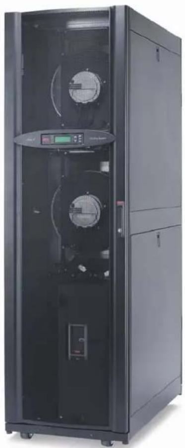
natural_image
Exterior view of a black industrial rack cabinet with dual circular fans and control panel (no visible text or symbols)AIR-COOLED
ACRP100
ACRP101
ACRP102
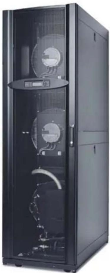
natural_image
Exterior view of a black server cabinet with open doors showing internal components (no visible text or labels)CHILLED WATER
ACRP500
ACRP501
ACRP502
Technical Data
American Power Conversion Legal Disclaimer
The information presented in this manual is not warranted by the American Power Conversion Corporation to be authoritative, error free, or complete. This publication is not meant to be a substitute for a detailed operational and site specific development plan. Therefore, American Power Conversion Corporation assumes no liability for damages, violations of codes, improper installation, system failures, or any other problems that could arise based on the use of this Publication.
The information contained in this Publication is provided as is and has been prepared solely for the purpose of evaluating data center design and construction. This Publication has been compiled in good faith by American Power Conversion Corporation. However, no representation is made or warranty given, either express or implied, as to the completeness or accuracy of the information this Publication contains.
IN NO EVENT SHALL AMERICAN POWER CONVERSION CORPORATION, OR ANY PARENT, AFFILIATE OR SUBSIDIARY COMPANY OF AMERICAN POWER CONVERSION CORPORATION OR THEIR RESPECTIVE OFFICERS, DIRECTORS, OR EMPLOYEES BE LIABLE FOR ANY DIRECT, INDIRECT, CONSEQUENTIAL, PUNITIVE, SPECIAL, OR INCIDENTAL DAMAGES (INCLUDING, WITHOUT LIMITATION, DAMAGES FOR LOSS OF BUSINESS, CONTRACT, REVENUE, DATA, INFORMATION, OR BUSINESS INTERRUPTION) RESULTING FROM, ARISING OUT, OR IN CONNECTION WITH THE USE OF, OR INABILITY TO USE THIS PUBLICATION OR THE CONTENT, EVEN IF AMERICAN POWER CONVERSION CORPORATION HAS BEEN EXPRESSLY ADVISED OF THE POSSIBILITY OF SUCH DAMAGES. AMERICAN POWER CONVERSION CORPORATION RESERVES THE RIGHT TO MAKE CHANGES OR UPDATES WITH RESPECT TO OR IN THE CONTENT OF THE PUBLICATION OR THE FORMAT THEREOF AT ANY TIME WITHOUT NOTICE.
Copyright, intellectual, and all other proprietary rights in the content (including but not limited to software, audio, video, text, and photographs) rests with American Power Conversion Corporation or its licensors. All rights in the content not expressly granted herein are reserved. No rights of any kind are licensed or assigned or shall otherwise pass to persons accessing this information.
This Publication shall not be for resale in whole or in part.
Contents
Overview 1
Capacity 1
Room Air Distribution 1
Configuration....1
Compliance Approval .... 1
Chilled Water Standard Features 1
Air-cooled Standard Features 1
Accessories ....1
Scalable Solution for Critical Environments ...... 2
InRow Advantages ....2
Scalable for High Density 2
Hot Aisle Containment System....3
Standard Features.... 4
Insulated Cabinet 4
Variable Speed Fans 4
Shutdown Input/Alarm Output 4
Chilled Water Flow Meter 4
2-way/3-way Floating Point Valve (CW Only) 4
Counterflow Cooling Coil/Condensate Pan 4
Electric Reheat 4
30% ASHRAE 52.1 Filter .....4
Pipe Adapters (CW only) 4
Pipe Adapters (Air-Cooled only) 4
Selectable Top or Bottom Piping Connections ....4
Dual Position Float Condensate Management ....5
Network Management Card 5
Bay Kit InRow RP/NetShelter SX 5
Remote Temperature Sensors .... 5
Humidifier 5
Optional Features.... 6
Cable Water Detector 6
Network Cable 6
85% ASHRAE 52.1 Filter .....6
Power Trough 6
Data Partition 6
Height Adapters 6
Flex Hose Piping Kits 6
Microprocessor Controller 7
Microprocessor Controller 7
Open Architecture 7
Control Type 7
Functions 7
Logging 7
Control 7
Alarms 8
Chilled Water Only Alarms 8
Air-cooled Only Alarms 8
InRow RP Models 9
Chilled Water Interior Components (front of unit) .....10
Air-cooled Interior Components (front of unit) .....12
Air-cooled Interior Components (back of unit) .....13
Chilled Water and Air-cooled User Interface Connections .....14
Chilled Water Electrical Panel 15
Air-cooled Electrical Panel 16
Performance Specifications 17
Chilled Water Performance Specifications 5.5°C (42°F) EWT . . . .17
Chilled Water Performance Specifications 7.2°C (45°F) EWT . . . .18
Chilled Water Performance Specifications 8.9°C (48°F) EWT . . . .19
Chilled Water Performance Specifications 10°C (50°F) EWT ....20
Chilled Water Performance Specifications 12.8°C (55°F) EWT . . .21
Chilled Water Performance Specifications 15.5°C (60°F) EWT . . .22
Chilled Water Data - General .....23
Glycol Correction Factors 24
Altitude Correction Factors for InRow Products .....24
Air-cooled Performance Specifications .....24
Air-cooled Data - General 25
Sound Performance Data 26
Electrical Data 26
Dimensional Data 27
InRow RP Assembled Module .....27
SX to VX Height Adapter....28
SX to 48U SX Height Adapter .....28
Piping and Mechanical Connections.... 29
Chilled Water Piping Diagram .....29
Top Chilled WaterPiping Access (top view) .....30
Air-cooled Piping Diagram 32
Air-cooled Piping Access (top) .....33
Air-Cooled Condensers 35
Mechanical Data ....35
Electrical Data 35
ACCD75201 and ACCD75204 ....36
ACCD75202 and ACCD75205 .....36
ACCD75203 and ACCD75206 36
ACCD75207 37
ACCD75208 and ACCD75209 37
Air-cooled Condenser Features ....37
Guide Specifications....38
Guidelines for Installation 44
Room preparation 44
Service access 44
Receiving the Unit 44
Rigging 44
Condensate Drain 44
The modular, row-based computer room cooling system offers efficient, predictable, and economical cooling for a variety of spaces.
Critical environmental requirements now reach far beyond the confines of the traditional data center or computer room to encompass a larger suite of applications, referred to as technology rooms. Critical environment applications include:
- Computer rooms
• Telecommunication facilities - Clean rooms
- Power equipment
• Medical equipment rooms
• LAN/WAN environments
A worldwide network of APC representatives is fully qualified to provide engineering, sales, installation, and service for our products.
APC warrants all parts for 18 months from shipment and 12 months from startup. Extended warranties are available.
Capacity
The InRow RP chilled water configuration is available in one size with a capacity that is up to 60 kW based on the particular application of the unit. The InRow RP air-cooled configuration is available in one size with a capacity that is up to 37 kW.
Room Air Distribution
Row-based systems are placed in line with rack enclosures. At least one system is used per hot aisle. Air is drawn in through the rear of the system, cooled, and discharged into the cold aisle, thereby neutralizing the sensible heating effects of the data processing equipment. The InRow RP delivers high volumes of airflow to eliminate hot spots in densely populated environments.
Configuration
- Chilled Water
- Air-cooled
Compliance Approval
• U L L i s t e d
• VDE
• CE
• C - t i c k
• C - U L L i s t e d

Chilled Water Standard Features
- Insulated cabinet
- Backward inclined impeller
• Variable speed fans (3) - Shutdown input/alarm output
- Chilled water flow meter
• 2-way/3-way floating point valve - Humidifier
- Counter flow cooling coil
- Electric reheat
- Pleated 100mm (4 in) filter
• NPT to BSPT pipe adapters - Top or bottom piping
- Condensate management with dual position float
• Network management card - Baying Kit InRow RP to NetShelter® SX rack
• Remote temperature sensor (3) - Microprocessor controller
• Automatic transfer switch
Air-cooled Standard Features
- Insulated cabinet
• Backward inclined impeller
• Variable speed fans (2) - Shutdown input/alarm output
- Humidifier
• Cross circuited cooling coil
• Electric reheat
- Pleated 100mm (4 in) filter
- Pipe adapters
- Top or bottom piping
- Condensate management with dual position float
• Network management card
- Baying kit InRow RP to NetShelter® SX rack
• Remote temperature sensor (3)
- Microprocessor controller
- Variable speed reciprocating compressor using VFD control
• Liquid line solenoid valve
• Pressure equalization solenoid
Accessories
- Cable leak detector
- Baying kit InRow RP to NetShelter VX rack
- NetShelter SX 42U to 48U height adapters
• NetShelter VX 42U height adapters
• Bridge trough power cable shield
• Data cable bridge partition - Flex hose piping kits
Scalable Solution for Critical Environments
InRow Advantages
The row-based solution improves energy efficiency and cooling ability in a number of ways. First, the InRow RP draws air directly from the hot aisle, allowing the InRow RP to take advantage of higher heat transfer efficiency due to higher temperature differences. It can then discharge room temperature air directly in front of the servers it is cooling. This increases energy efficiency by allowing the chiller to operate at higher leaving water temperatures. Placing the cooling unit in the row enables the unit to operate at higher return and supply air temperatures, yielding 100% sensible capacity. This significantly reduces the need for humidification.
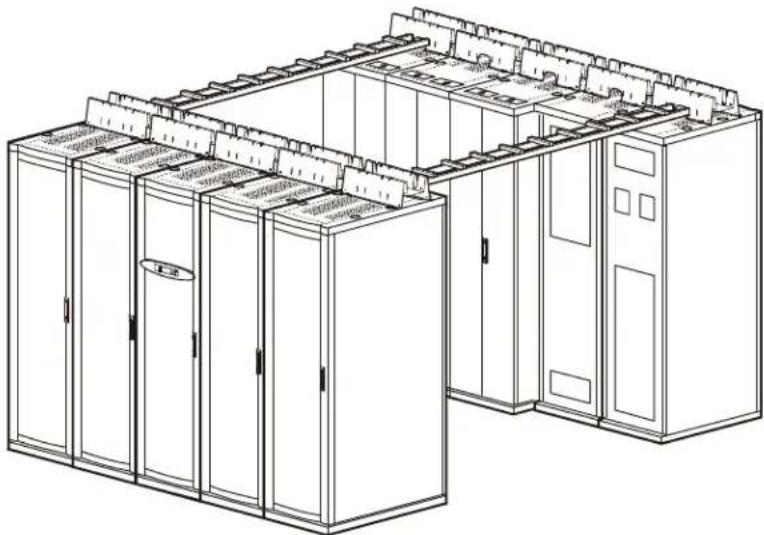
natural_image
Line drawing of a server rack system with multiple units and control panels (no text or labels)Scalable for High Density
The predictable performance of the row-based architecture makes it well suited for high density applications. The focus on heat removal instead of cold air delivery is the key to making this approach scalable. The modular design of the InRow RP allows it to be easily added in the row as the demand for cooling increases.
The additional benefit of the row-based architecture is the ability to add hot aisle containment. Containing the hot aisle further reduces any chance of hot and cold air streams mixing. This provides ultimate predictability and allows the cooling capacity to be matched to the IT heat load.
Hot Aisle Containment System
Modular ceiling tiles and doors can be used to enclose the hot aisle. This increases the densities that can be handled in a single rack enclosure by eliminating mixing of hot and cold air streams. This method, called load neutralization, removes the heat from the hot aisle, cools it, and then returns it to the surrounding room area at or slightly below room temperature. The warmer return air temperatures that are achieved in this application increase the capacity of the air conditioner.
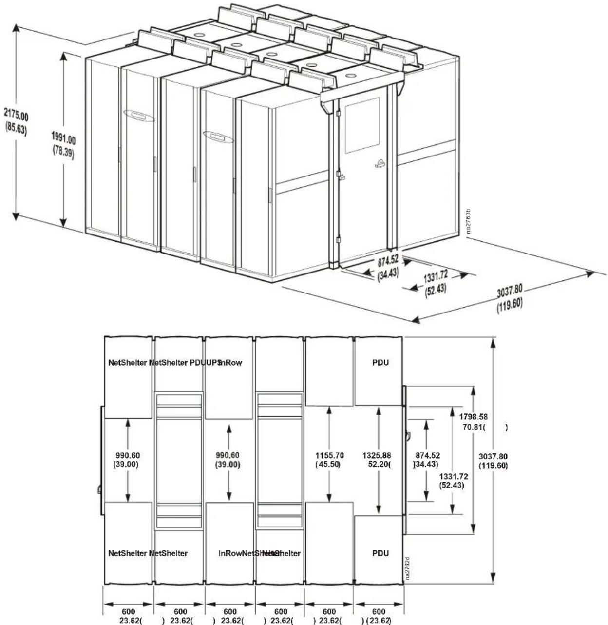
Use of modular ceiling tiles across a 914.4 mm (3 ft) hot aisle that connects two opposite rack enclosures makes expansion quick and simple. Expansion kits, with necessary ceiling tile and all baying hardware, can be ordered to increase the size of the hot aisle by one rack on each side. The end doors can be easily removed and re-attached for expansion.
The enclosed hot aisle prevents any warm return air from mixing with cold supply air. In effect, all surrounding room air can act as supply air to the system. The hot aisle containment system is beneficial in any environment. It can be deployed quickly in any controlled space without expensive additions to the infrastructure, such as raised floor or ductwork.
other
| Dimension | Value | | --------- | ----- | | Top Left Panel (Width) | 2175.00 (85.63) | | Top Right Panel (Width) | 1991.00 (78.39) | | Bottom Left Panel (Width) | 874.52 (34.43) | | Bottom Right Panel (Width) | 3037.80 (119.60) | | Bottom Left Panel (Width) | 990.60 (39.00) | | Bottom Right Panel (Width) | 1798.58 (70.81) | | Bottom Left Panel (Width) | 990.60 (39.00) | | Bottom Right Panel (Width) | 3037.80 (119.60) | | Bottom Left Panel (Width) | 1155.70 (45.50) | | Bottom Right Panel (Width) | 1325.88 (52.20) | | Bottom Left Panel (Width) | 874.52 (34.43) | | Bottom Right Panel (Width) | 1331.72 (52.43) | | Bottom Left Panel (Width) | 990.60 (39.00) | | Bottom Right Panel (Width) | 1798.58 (70.81) | | Bottom Left Panel (Width) | 1155.70 (45.50) | | Bottom Right Panel (Width) | 1325.88 (52.20) | | Bottom Left Panel (Width) | 874.52 (34.43) | | Bottom Right Panel (Width) | 1331.72 (52.43) | | Bottom Right Panel (Width) | 3037.80 (119.60) | | Bottom Left Panel (Width) | 990.60 (39.00) | | Bottom Right Panel (Width) | 1798.58 (70.81) | | Bottom Left Panel (Width) | 1155.70 (45.50) | | Bottom Right Panel (Width) | 1325.88 (52.20) | | Bottom Right Panel (Width) | 1798.58 (70.81) | | Bottom Left Panel (Width) | 990.60 (39.00) | | Bottom Right Panel (Width) | 1798.58 (70.81) | | Bottom Left Panel (Width) | 1155.70 (45.50) | | Bottom Right Panel (Width) | 1325.88 (52.20) | | BottomRight Panel (Width) | 1798.58 (70.81) | | BottomRight Panel (Width) | 3037.80 (119.60) | | BottomLeft Panel (Width) | 600 (23.62) | | BottomRight Panel (Width) | 600 (23.62) | | BottomLeft Panel (Width) | 600 (23.62) | | BottomRight Panel (Width) | 600 (23.62) | | BottomRight Panel (Width) | 600 (23.62) | | BottomLeft Panel (Width) | 600 (23.62) | | BottomRight Panel (Width) | 600 (23.62) | | BottomRight Panel (Width) | 600 (23.62)Dimensions are shown in mm (in).
Standard Features
Insulated Cabinet

The frame is constructed of 1.5 mm (16 gauge) formed steel for maximum strength. Cabinet is serviceable from the front and rear. All exterior panels and corner posts on the frame are powder coated for durability and an attractive finish. Front and rear exterior panel are constructed of 1.2 mm (18 gauge) perforated steel with 69.5% open free area. Insulation is 80.1 kg/m ^3 (5 lb/ft ^3 ) density and complies with ASTM E84 rating of 25/50. All panels include a key latch for safety and security for easy access and removal.
Variable Speed Fans
natural_image
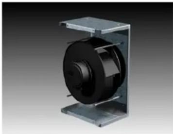
3D rendering of a mechanical component with a black cylindrical body and metal frame (no text or symbols visible)The InRow RP unit is equipped with variable speed, electrically commutated, 400 mm (15.8-in) backward incline, direct drive fans. The chilled water unit is equipped with three fans while the air-cooled unit has two. In order to provide uniform airflow over the cooling coil, the fans provide a draw-through air pattern. Fans are easily serviced in the field.
Shutdown Input/Alarm Output
The unit provides one field connection input for remote shutdown and one field connection alarm output.
Chilled Water Flow Meter
Internal piping of the unit includes a flow meter wired into the microprocessor controller to display chilled water flow and determine operating performance.
2-way/3-way Floating Point Valve (CW Only)
A floating point valve is microprocessor controlled to regulate the amount of chilled water into the cooling coil to maintain desired conditions. The standard valve pressure rating is 4136.8 kPa (600 psig). The maximum operation pressure of the unit is 2068.4 kPa (300 psig). The valve is user configurable to be two-way or three-way.
Counterflow Cooling Coil/Condensate Pan
Designed for high sensible heat ratios, the coil is constructed with copper tubes, raised lance type aluminum fins, and 1.2 mm (18 gauge) galvanized steel end plates. Coil headers are equipped with anti drip shields in case of condensation. Condensate pan is UL94 V-0 thermal formed non-ferrous material sloped for positive drainage for higher indoor air quality.
Electric Reheat
Electric reheat elements are low watt density, wired for three-phase and loaded equally on all three phases, and electrically and thermally protected by both automatic and manual reset thermal cut outs. Reheat elements are stainless steel, fin tubular construction.
30% ASHRAE 52.1 Filter
The filtration of conditioned air is extremely vital to maintaining the clean, particle-free environment required by electrical equipment. The system uses a 30% efficient, 100 mm (4 in), deep loading, pleated filter. Deeper filters produce a lower pressure drop, requiring less energy during normal operation. The filter is moisture resistant up to a 100% relative humidity. Filters are easily replaceable from the rear of the unit. (MERV 8 per ASHRAE 52.2, EN779 G4)
Pipe Adapters (CW only)
Standard pipe connections are 38.1 mm (1 1/2 in) NPSM (manufactured in accordance with ANSI B.1.20.1).
Pipe Adapters (Air-Cooled only)
Standard pipe connections are 31.75 mm (1 1/4 in) 12 UNF female Rotolock (manufactured in accordance with ANSI B1.1). The adapter converts the rotolock to a swat adapter.
Selectable Top or Bottom Piping Connections
Unit includes both top and bottom piping connections. Top piping connects to internal stubs and routes piping upward out of the unit. Bottom piping connects to internal stubs and routes piping downward out of the unit. All connections utilize unions or rotolok fittings for ease of installation and service
Dual Position Float Condensate Management
The pump is factory wired and piped internally to the condensate drain pan and humidifier outlet. The pump is capable of pumping a maximum of 18 m (60 ft) at 0.009 l/s (8.45 GPH), which may include a maximum lift of 3.5 m (11.5 ft) of head. A dual position float is included with the unit. One position is used for condensate pump control, the other to alarm condensate pump failure which shuts down the RP to prevent condensate pump overflow.
Network Management Card
Permits multi-level access to monitoring, control, and event notification features over the user's network.
Bay Kit InRow RP/NetShelter SX
Baying kits made of 1.5 mm (16 gauge) steel enable baying of the cooling system to APC NetShelter SX enclosures.
Remote Temperature Sensors
To control the unit based on rack inlet temperature, three remote sensors are provided. These sensors measure at 4 m (13 ft) from the connection point inside the RP. The sensors are used for remote placement in the field on adjacent IT racks.
Humidifier
The humidifier is a self-contained, steam-generating type, factory piped and wired, with a disposable cylinder and an automatic solid state control circuit. Humidifier canisters are replaceable. The humidifier controller communicates directly to the microprocessor controller and provides complete status and control at the operator interface.
Optional Features
Cable Water Detector
A leak detection cable is placed on the floor or subfloor around all possible leak sources. If water or other conductive liquids contact the cable anywhere along its length, the microprocessor controller announces the leak visually, audibly, and across the network. The 6.1 m (20 ft) cable may be cascaded to make custom lengths up to 24.4 m (80 ft).
Network Cable
Various lengths of network cable are available to ship with your cooling system. The network cable is used to interconnect multiple cooling units in a redundant group, as well as to connect the network management card to your LAN.
85% ASHRAE 52.1 Filter
Electrical equipment requires clean, particle free air, thus making the filtration of the air extremely important. Optionally, the system uses a 85% efficient, 100 mm (4 in), deep loading, pleated filter. Deeper filters produce a lower pressure drop, requiring less energy during normal operation. The 100% synthetic media will not absorb moisture and is resistant to most common chemicals. The filter is moisture resistant up to a 100% relative humidity. Filters are easily replaceable from the rear of the unit. (MERV 13 per ASHRAE 52.2, EN779 F7)
Power Trough
Overhead power distribution between adjacent NetShelter racks allows for removal of the InRow RP without disrupting overhead power cabling.
Data Partition
Overhead cable distribution between adjacent NetShelter racks allows for removal of the InRow RP without disrupting overhead cabling.
Height Adapters
To match height of the InRow RP to various rack heights, height adapters are available for NetShelter 42U VX and 48U SX racks.
Flex Hose Piping Kits
For hard piping to the chilled water InRow RP, stainless steel flex piping kits are available. The kits ship with two 0.914 m (3 ft) or 1.828 m (6 ft) pipes, depending on selection. Connections are 1.25 in NPT to 1.5 in NPSM, OFS female.
Microprocessor Controller
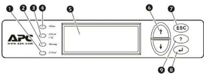
Microprocessor Controller
The microprocessor controller is standard on each system. The controller provides precision control for the demanding requirements of:
- Computer rooms
• Telecommunication facilities - Clean rooms
- Power equipment
• Medical equipment rooms
• LAN/WAN environments
The easy-to-use display allows the operator to select options from the device's menu-driven interface to control and monitor the connected air conditioning system.
Open Architecture
The InRow RP protocol is open for integration with all building management systems.
Communication interface on the system can be MODBUS RS485 or Ethernet.
Control Type
Controller utilizes proportional/ integral/derivative (PID), a time-proven precision environmental control method. This allows for custom tuning of control variables to achieve desired system response.
Functions
• Supply and Return Air Conditions
• Operational Mode Control
- Event Logging
- Alarms
- Redundant Group Control
• Fan Speed Adjustment
- Input/Output Module Programming
| 1 | Critical Alarm LED |
| 2 | Warning Alarm LED |
| 3 | Check Log LED |
| 4 | Status LED |
| 5 | Liquid Crystal Display (LCD) |
| 6 | Menu Selection scroll keys |
| 7 | Escape key |
| 8 | Enter key |
| 9 | Help key |
Logging
The event log keeps a record of all alarms and events. Each event log contains a time/date stamp as well as operating conditions at the time of occurrence. The controller also displays run time, in hours, for major components (air filters, fans, and condensate pump, as well as humidifier, heater, and compressor for the air-cooled unit).
Control
The backlit, four-line by twenty-character display is password configurable.
Alarms
The microprocessor controller shall activate a visible and audible alarm in the following occurrences:
- Cool Fail
- Rack inlet temperature violation
- Rack inlet temperature sensor fault
- Air filter clogged
• Air filter run hours exceeded - Filter DP sensor failure
• Supply air sensor fault - Return air sensor fault
• Supply air high temperature violation - Return air high temperature violation
- Fan fault
• Fan run hours exceeded
• Water detection fault - Condensate pump fault
• Condensate run hours exceeded
• Humidifier water conductivity high violation
• Humidifier fault tolerance exceeded
• Humidifier low water
• Humidifier excessive output reduction - Humidifier drain fault
• Humidifier cylinder full
• Humidifier replace cylinder
• Humidifier RS485 communication fault
• Humidifier run hours violation
• Humidity high/low violation
• Supply humidity sensor fault - Return humidity sensor fault
- Heater fault
• Heater run hours exceeded
• Heater interlock shutdown - Group communication fault
- Internal communication fault
• A-link isolation relay fault
• External communication fault - Input contact fault
- Invalid supply setpoint
- Idle mode active
Chilled Water Only Alarms
- Coil fluid valve actuator fault
- Fluid flow fault
- Entering fluid temperature high violation
- Entering fluid temperature sensor fault
• Leaving fluid temperature sensor fault
• Power source failure - Fluid calibration
Air-cooled Only Alarms
• High discharge pressure
- Low suction pressure
• High suction pressure
- Compressor drive failure
- Compressor drive warning
- Compressor run hours violation
- Compressor drive RS485 communication fault
• Excessive compressor cycling
• Air flow decreased while compressor off
• Suction pressure sensor failure
• Discharge pressure sensor failure
• High pressure switch active
- Fan speed decreased to avoid high pressure (event only)
- Compressor speed decreased to avoid high pressure (event only)
- Compressor high pressure
- Oil return pump active
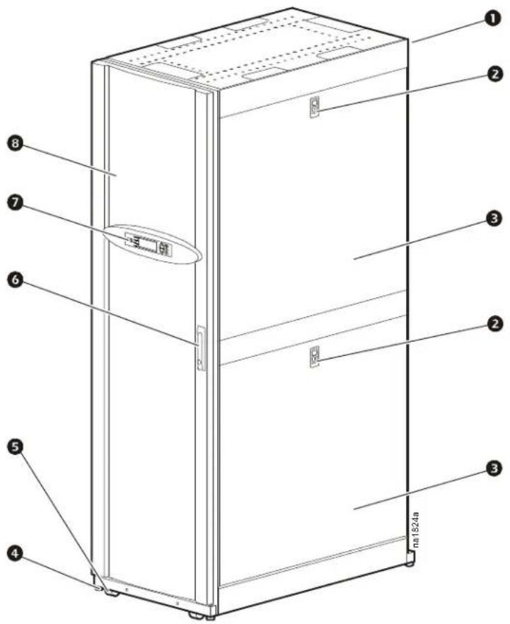
① Hinged rear doors
⑤ Casters (all swiveling)
② Side panel lock
6 Door handle and lock
③ Removable side panel
⑦ Display interface
4 Adjustable leveling foot
8 Hinged front door
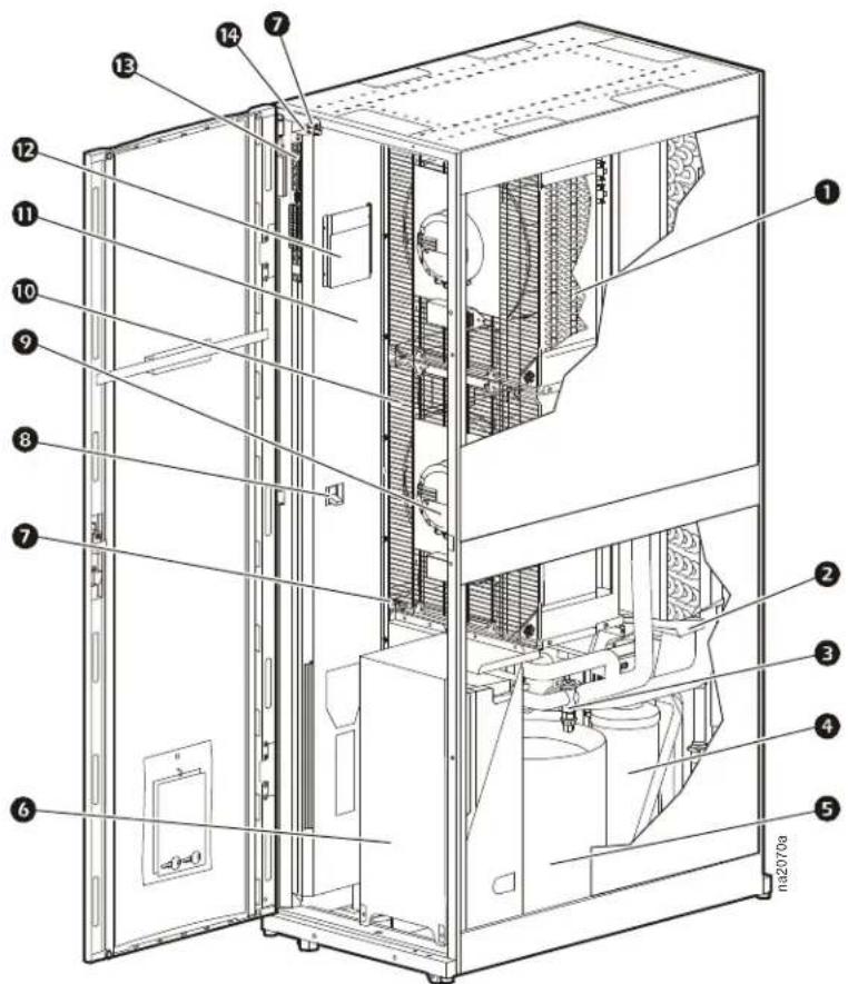
Chilled Water Interior Components (front of unit)
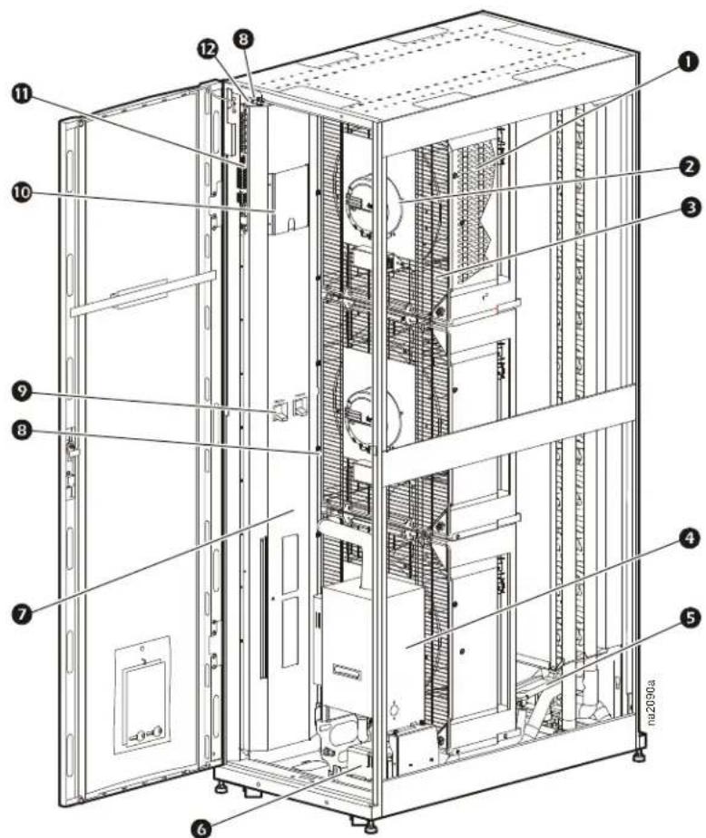
① Electric heater (for reheat)
2 Fan
3 Fan guard
4 Humidifier
5 Condensate drain pan
6 Condensate pump
⑦ Electrical panel
⑧ Supply temperature sensors
9 Main feed breakers
10 Ladder diagrams
⑪ User interface connectors
⑫ Supply humidity sensor
Chilled Water Interior Components (back of unit)
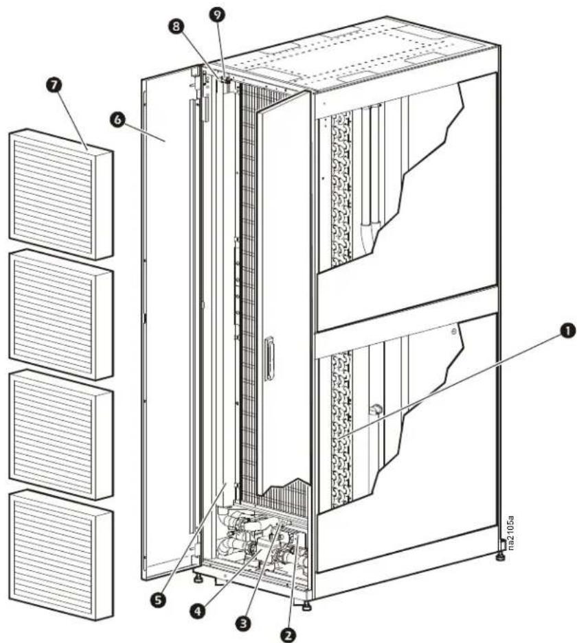
① Chilled water coil
6 Rear doors
② Chilled water control actuator
7 Air filters
③ Chilled water three-way valve body
⑧ Return humidity sensor
4 Flow meter
9 Return temperature sensor
5 Pipe chase
Air-cooled Interior Components (front of unit)
① Electric heater (for reheat)
② Condensate drain pan
③ Thermal expansion valve
4 Receiver
5 Compressor
6 Variable Frequency Drive (for compressor)
⑦ Supply air temperature sensor
8 Main circuit breaker
9 Fan
10 Fan guard
11 Electrical panel
12 Ladder diagrams
13 Communication and external device connectors
14 Humidity sensor
Air-cooled Interior Components (back of unit)
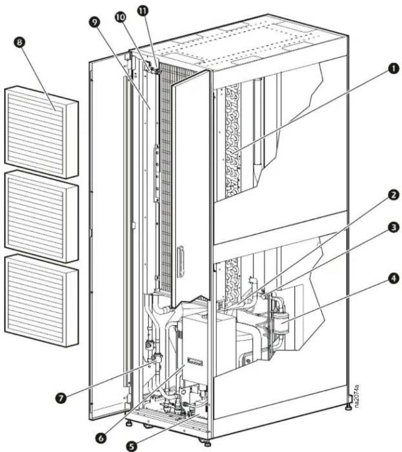
① Evaporator coil
⑦ Shutoff valves (top piping only)
2 Condensate drain pan
8 Air filters
3 Sight glass
9 Pipe chase
4 Filter dryer
⑩ Humidity sensor
5 Condensate pump
⑪ Return air temperature sensor
6 Humidifier
Chilled Water and Air-cooled User Interface Connections

1 Rack inlet temperature sensors 1, 2, 3
② A-Link IN
3 A-Link OUT
4 Network port
5 Console port
6 Alarm output, NC (Normally Closed)
7 Alarm output, COM (Common)
8 Alarm output, NO (Normally Open)
9 Supply GND (Ground)
10 Supply 12 Vdc (current limit: 20 mA)
⑪ Supply 24 Vdc (current limit: 20 mA)
⑫ Customer input + (12–30 Vac/Vdc, 24 Vdc @ 11 mA)
13 Supply COM
14 BMS D1 (RXTX+)
15 BMS D0 (RXTX-)
16 BMS GND
⑰ Supply air temperature sensor (front)
18 Supply air humidity sensor (front)
19 Display interface

Note: For a top installation, control wiring is routed through the wire channel located at the top left hand corner just above the user interface connectors.
For a bottom installation, the control wiring is routed to the access hole in the bottom of the equipment through wire clamps from the interface connectors. Then, the wiring is routed down along the electrical panel and secured with wire clamps.
Chilled Water Electrical Panel

Note: ACRP501 shown.
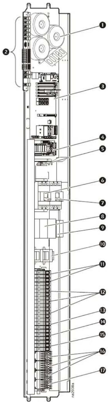
1 Transformers
② User interface connectors
3 Main controller board
4 Relay board
5 Ground lug
6 Main circuit breaker — power feed A
⑦ Main circuit breaker — power feed B
8 Automatic transfer switch (ATS) contactors
9 ATS timers
10 ATS transformer (ACRP501 only)
⑪ ATS timer circuit breakers
12 Fan circuit breakers
13 Controller circuit breaker
14 Humidifier circuit breaker
15 Heater circuit breaker
16 Heater contactors
⑰ Humidifier contactor
Air-cooled Electrical Panel

Note: ACRP 101 shown.
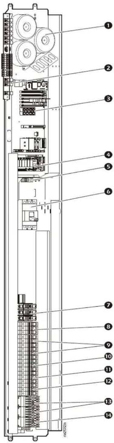
1 Transformers
② User interface connectors
3 Main controller board
4 Relay board
5 Ground lug
6 Main circuit breaker
7 Compressor fuse block (ACRP100, ACRP101)
8 Compressor circuit breaker (ACRP102)
9 Fan circuit breakers
10 Controller circuit breaker
⑪ Humidifier circuit breaker
12 Heater circuit breaker
13 Heater contactors
14 Humidifier contactor
Performance Specifications
Chilled Water Performance Specifications 5.5°C (42°F) EWT
| Temperature dry bulb (DB), wet bulb (WB) °C (°F) | CW Delta T °C (°F) | Total Net Capacity kW (BTU/hr) | Sensible Net Capacity kW (BTU/hr) | Sensible Heat Ratio SHR | CW Flow Rate l/s (GPM) | Total CW Pressure Drop kPa (ft H2O)* |
| 26.7°C DB, 17.1°C WB (80°F DB, 62.8°F WB) | ||||||
| 6.6 (12) 44.3 | (151,000) 40.7 (1 | 39,000) 0.92 1.6 (2 | 5.9) 66 (21.95) | |||
| 7.7 (14) 40.8 | (139,000) 37.9 (1 | 29,000) 0.93 1.3 (2 | 0.6) 42 (14.1) | |||
| 8.8 (16) 37.8 | (129,000) 35.2 (1 | 20,000) 0.93 1.1 (1 | 6.8) 29 (9.5) | |||
| 10 (18) 34.6 | (118,000) 32.5 (1 | 1,000) 0.94 0.9 (1 | 3.8) 19 (6.5) | |||
| 11.1 (20) 31.8 | (109,000) 29.9 (1 | 02,000) 0.94 0.7 (1 | 1.5) 14 (4.6) | |||
| 29.4°C DB, 18.1°C WB (85°F DB, 64.5°F WB) | ||||||
| 6.6 (12) 50.8 | (174,000) 47.8 (1 | 63,000) 0.94 1.9 (2 | 9.5) 84 (28.4) | |||
| 7.7 (14) 47.7 | (163,000) 44.8 (1 | 53,000) 0.94 1.5 (2 | 3.9) 56 (18.7) | |||
| 8.8 (16) 44.1 | (151,000) 41.9 (1 | 43,000) 0.95 1.2 (1 | 9.4) 38 (12.5) | |||
| 10 (18) 41.2 | (141,000) 39.1 (1 | 4,000) 0.95 1.0 (1 | 6.2) 26 (8.8) | |||
| 11.1 (20) 37.8 | (129,000) 36.3 (1 | 24,000) 0.96 0.8 (1 | 3.5) 19 (6.2) | |||
| 32.2°C DB, 18.9°C WB (90°F DB, 66.1°F WB) | ||||||
| 7.7 (14) 54.5 | (186,000) 52.3 (1 | 79,000) 0.96 1.7 (2 | 7.1) 71 (23.8) | |||
| 8.8 (16) 51.4 | (175,000) 49.3 (1 | 68,000) 0.96 1.4 (2 | 2.4) 49 (16.6) | |||
| 10 (18) 47.8 | (163,000) 46.3 (1 | 58,000) 0.97 1.2 (1 | 8.6) 35 (11.6) | |||
| 11.1 (20) 44.8 | (153,000) 43.4 (1 | 48,000) 0.97 1.0 (1 | 5.7) 25 (8.32) | |||
| 35.0°C DB, 19.8°C WB (95°F DB, 67.7°F WB) | ||||||
| 7.7 (14) 62.0 | (212,000) 60.2 (2 | 05,000) 0.97 1.9 (3 | 0.6) 90 (30.3) | |||
| 8.8 (16) 58.8 | (201,000) 57.0 (1 | 95,000) 0.97 1.6 (2 | 5.4) 63 (21.3) | |||
| 10 (18) 55.6 | (190,000) 53.9 (1 | 4,000) 0.97 1.4 (2 | 45 (15.2) | |||
| 11.1 (20) 52.4 | (179,000) 50.9 (1 | 74,000) 0.97 1.2 (1 | 8.3) 33 (11.1) | |||
| 37.8°C DB, 20.7°C WB (100°F DB, 69.2°F WB) | ||||||
| 8.8 (16) 66.4 | (227,000) 65.0 (2 | 22,000) 0.98 1.8 (2 | 8.6) 79 (26.6) | |||
| 10 (18) 63.1 | (215,000) 61.8 (2 | 1,000) 0.98 1.5 (2 | 4.2) 57 (19.2) | |||
| 11.1 (20) 59.8 | (204,000) 58.7 (2 | 200,000) 0.98 1.3 (2 | 0.7) 42 (14.3) | |||
| 40.6°C DB, 21.6°C WB (105°F DB, 70.8°F WB) | ||||||
| 10 (18) 71.4 | (244,000) 70.0 (2 | 39,000) 0.98 1.7 (2 | 7.3) 72 (24.3) | |||
| 11.1 (20) 68.1 | (233,000) 66.7 (2 | 28,000) 0.98 1.5 (2 | 3.4) 54 (18.02) | |||
Note: All values are accurate to +/- 5% and based on full speed with standard filters.
Note: Reduce airflow and cooling capacity specifications by 7% for cooling units run at low input voltage (380 V).
Note: Any CW flow rate of 0.19 l/s - 0.32 l/s (3.0 GPM - 5.0 GPM) may cause an increased error in flow rate and power calculation. A fluid flow fault may result. Any flow rate under 0.19 l/s (3.0 GPM) may also display as 0 in the flow rate and power calculation.
Note: For sustained operation, a maximum flow rate of 2.2 l/s (34 GPM) is recommended. This may be exceeded by 25% for peak conditions.
* To convert feet of water to PSIG, use the following formula: ft H₂O ÷ 2.307 = PSIG.
Chilled Water Performance Specifications 7.2°C (45°F) EWT
| Temperature dry bulb (DB), wet bulb (WB) °C (°F) | CW Delta T °C (°F) | Total Net Capacity kW (BTU/hr) | Sensible Net Capacity kW (BTU/hr) | Sensible Heat Ratio SHR | CW Flow Rate l/s (GPM) | Total CW Pressure Drop kPa (ft H2O)* |
| 26.7°C DB, 17.1°C WB (80°F DB, 62.8°F WB) | ||||||
| 5.5 (10) 40.8 | (139,000) 39.6 (135,000) 0.97 1.8 | (28.8) 81 (27.03) | ||||
| 6.6 (12) 37.9 | (130,000) 36.8 (126,000) 0.97 1.4 | (22.5) 50 (16.6) | ||||
| 7.7 (14) 35.1 | (120,000) 34.1 (16,000) 0.97 1.1 | (18.0) 32 (10.9) | ||||
| 8.8 (16) 32.5 | (111,000) 31.5 (108,000) 0.97 0.9 | (14.6) 22 (7.4) | ||||
| 10 (18) 29.8 | (102,000) 28.9 (99,000) | 0.97 0.8 (12.0) 15 (5.1) | ||||
| 11.1 (20) 27.3 | (93,000) 26.5 (90,000) | 0.97 0.6 (10.0) 11 | (3.7) | |||
| 29.4°C DB, 18.1°C WB (85°F DB, 64.5°F WB) | ||||||
| 6.6 (12) 45.0 | (154,000) 43.7 (149,000) 0.97 1.7 | (26.4) 68 (22.6) | ||||
| 7.7 (14) 42.0 | (144,000) 40.8 (139,000) 0.97 1.3 | (21.2) 44 (14.8) | ||||
| 8.8 (16) 39.1 | (134,000) 38.0 (130,000) 0.97 1.1 | (17.4) 30 (10.2) | ||||
| 10 (18) 36.3 | (124,000) 35.2 (120,000) 0.97 0.9 | (14.4) 21 (7.2) | ||||
| 11.1 (20) | 33.3 (114,000) | 32.6 (111,000) 0.98 | 0.8 (11.9) | 15 (5.1) | ||
| 32.2°C DB, 18.9°C WB (90°F DB, 66.1°F WB) | ||||||
| 6.6 (12) 52.3 | (179,000) 51.2 (175,000) 0.98 1.9 | (30.4) 89 (29.8) | ||||
| 7.7 (14) 49.2 | (168,000) 48.2 (165,000) 0.98 1.5 | (24.5) 59 (19.9) | ||||
| 8.8 (16) 46.1 | (157,000) 45.2 (154,000) 0.98 1.3 | (20.2) 41 (13.6) | ||||
| 10 (18) 42.7 | (146,000) 42.3 (144,000) 0.99 1.1 | (16.7) 28 (9.5) | ||||
| 11.1 (20) | 39.8 (136,000) | 39.4 (135,000) 0.99 | 0.9 (14.1) | 20 (6.9) | ||
| 35.0°C DB, 19.8°C WB (95°F DB, 67.7°F WB) | ||||||
| 7.7 (14) 57.2 | (195,000) 56.0 (191,000) 0.98 1.8 | (28.3) 78 (26.1) | ||||
| 8.8 (16) 53.4 | (182,000) 52.9 (181,000) 0.99 1.5 | (23.2) 53 (17.8) | ||||
| 10 (18) 50.3 | (172,000) 49.8 (170,000) 0.99 1.2 | (9.5) 38 (12.7) | ||||
| 11.1 (20) | 47.2 (161,000) | 46.7 (160,000) 0.99 | 1.0 (16.5) | 28 (9.2) | ||
| 37.8°C DB, 20.7°C WB (100°F DB, 69.2°F WB) | ||||||
| 8.8 (16) 61.6 | (210,000) 61.0 (208,000) 0.99 1.7 | (26.6) 69 (23.1) | ||||
| 10 (18) 58.3 | (199,000) 57.7 (197,000) 0.99 1.4 | (22.4) 50 (16.6) | ||||
| 11.1 (20) | 55.1 (188,000) | 54.5 (186,000) 0.99 | 1.2 (19.1) | 36 (12.2) | ||
| 40.6°C DB, 21.6°C WB (105°F DB, 70.8°F WB) | ||||||
| 8.8 (16) 69.6 | (238,000) 69.6 (238,000) 1.00 1.9 | (29.9) 86 (28.9) | ||||
| 10 (18) 66.1 | (226,000) 66.1 (226,000) 1.00 1.6 | (25.3) 63 (21.02) | ||||
| 11.1 (20) | 62.7 (214,000) | 62.7 (214,000) 1.00 | 1.4 (21.7) | 46 (15.5) | ||
Note: All values are accurate to +/- 5% and based on full speed with standard filters.
Note: Reduce airflow and cooling capacity specifications by 7% for cooling units run at low input voltage (380 V).
Note: Any CW flow rate of 0.19 l/s - 0.32 l/s (3.0 GPM - 5.0 GPM) may cause an increased error in flow rate and power calculation. A fluid flow fault may result. Any flow rate under 0.19 l/s (3.0 GPM) may also display as 0 in the flow rate and power calculation.
Note: For sustained operation, a maximum flow rate of 2.2 l/s (34 GPM) is recommended. This may be exceeded by 25% for peak conditions.
* To convert feet of water to PSIG, use the following formula: ft H₂O ÷ 2.307 = PSIG.
Chilled Water Performance Specifications 8.9°C (48°F) EWT
| Temperature dry bulb (DB), wet bulb (WB) °C (°F) | CW Delta T °C (°F) | Total Net Capacity kW (BTU/hr) | Sensible Net Capacity kW (BTU/hr) | Sensible Heat Ratio SHR | CW Flow Rate I/s (GPM) | Total CW Pressure Drop kPa (ft H2O)* |
| 26.7°C DB, 17.1°C WB (80°F DB, 62.8°F WB) | ||||||
| 5.5 (10) 35.7 | (122,000) 34.6 | (18,000) 0.97 1.6 | (25.5) 63 (21.3) | |||
| 6.6 (12) 32.9 | (112,000) 31.9 | (109,000) 0.97 1.2 | (19.7) 39 (12.9) | |||
| 7.7 (14) 30.3 | (103,000) 29.4 | (100,000) 0.97 1.0 | (15.7) 25 (8.3) | |||
| 8.8 (16) 27.7 | (95,000) 26.9 | (92,000) 0.97 0.8 | (12.7) 17 (5.5) | |||
| 10 (18) 25.3 | (86,000) 24.5 | (84,000) 0.97 0.7 | (10.4) 11 (3.9) | |||
| 11.1 (20) | 22.7 (78,000) | 22.3 (76,000) | 0.98 | 0.5 (8.5) | 8 (2.5) | |
| 29.4°C DB, 18.1°C WB (85°F DB, 64.5°F WB) | ||||||
| 5.5 (10) 42.3 | (145,000) 41.5 | (142,000) 0.98 1.9 | (29.9) 86 (28.9) | |||
| 6.6 (12) 39.4 | (134,000) 38.6 | (132,000) 0.98 1.5 | (23.3) 53 (17.8) | |||
| 7.7 (14) 36.5 | (125,000) 35.8 | (122,000) 0.98 1.2 | (18.6) | 35 (11.6) | ||
| 8.8 (16) 33.7 | (115,000) 33. | (113,000) 0.98 1. | (10.0) (15.1) 23 (7.9) | |||
| 10 (18) | 31.1 (106,000) | 30.4 (104,000) 0.98 | 0.8 (12.5) 16 (5.3) | |||
| 11.1 (20) | 28.5 (97,000) | 27.9 (95,000) 0.98 | 0.7 (10.4) 12 (3.9) | |||
| 32.2°C DB, 18.9°C WB (90°F DB, 66.1°F WB) | ||||||
| 6.6 (12) 47.0 | (161,000) 46.1 | (157,000) 0.98 1.7 | (27.5) 73 (24.5) | |||
| 7.7 (14) 43.9 | (150,000) 43.0 | (147,000) 0.98 1.4 | (22.1) 48 (16.2) | |||
| 8.8 (16) 40.9 | (140,000) 40.1 | (137,000) 0.98 1.1 | (18.1) 33 (10.9) | |||
| 10 (18) | 37.6 (128,000) | 37.2 (127,000) 0.99 | 0.9 (14.9) 23 (7.6) | |||
| 11.1 (20) | 34.8 (119,000) | 34.4 (118,000) 0.99 | 0.8 (12.5) 16 (5.3) | |||
| 35.0°C DB, 19.8°C WB (95°F DB, 67.7°F WB) | ||||||
| 7.7 (14) 51.4 | (176,000) 50.9 | (174,000) 0.99 1.6 | (25.6) 64 (21.5) | |||
| 8.8 (16) 48.2 | (165,000) 47.7 | (163,000) 0.99 1.3 | (21.1) 44 (14.8) | |||
| 10 (18) | 45.0 (154,000) | 44.6 (152,000) 0.99 | 1.1 (17.6) 31 (10.4) | |||
| 11.1 (20) | 42.0 (143,000) | 41.6 (142,000) | 0.99 0.9 (14.8) 22 | (7.6) | ||
| 37.8°C DB, 20.7°C WB (100°F DB, 69.2°F WB) | ||||||
| 7.7 (14) 60.0 | (205,000) | 59.4 (203,000) 0.99 1 | 9 (29.7) 85 (28.6) | |||
| 8.8 (16) | 56.0 (191,000) | 56.0 (191,000) | 1.00 | 1.5 (24.3) | 58 (19.4) | |
| 10 (18) | 52.6 (180,000) | 52.6 (180,000) | 1.00 | 1.3 (20.4) | 41 (13.9) | |
| 11.1 (20) | 49.4 (169,000) | 49.4 (169,000) | 1.00 1.1 (17.3) 30 | (9.9) | ||
| 40.6°C DB, 21.6°C WB (105°F DB, 70.8°F WB) | ||||||
| 7.7 (14) 68.6 | (234,000) | 68.6 (234,000) 1.00 2 | 1 (33.7) | 109 (36.5) | ||
| 8.8 (16) 64.9 | (222,000) | 64.9 (222,000) 1.00 1 | 8 (28.0) 76 (25.4) | |||
| 10 (18) | 61.3 (209,000) | 61.3 (209,000) | 1.00 1.5 (23.5) 54 | (18.2) | ||
Note: All values are accurate to +/- 5% and based on full speed with standard filters.
Note: Reduce airflow and cooling capacity specifications by 7% for cooling units run at low input voltage (380 V).
Note: Any CW flow rate of 0.19 l/s - 0.32 l/s (3.0 GPM - 5.0 GPM) may cause an increased error in flow rate and power calculation. A fluid flow fault may result. Any flow rate under 0.19 l/s (3.0 GPM) may also display as 0 in the flow rate and power calculation.
Note: For sustained operation, a maximum flow rate of 2.2 l/s (34 GPM) is recommended. This may be exceeded by 25% for peak conditions.
* To convert feet of water to PSIG, use the following formula: ft H₂O ÷ 2.307 = PSIG.
Chilled Water Performance Specifications 10°C (50°F) EWT
| Temperature dry bulb (DB), wet bulb (WB)°C (°F) | CW Delta T°C (°F) | Total Net Capacity kW (BTU/hr) | Sensible Net Capacity kW (BTU/hr) | Sensible Heat Ratio SHR | CW Flow Rate l/s (GPM) | Total CW Pressure Drop kPa (ft H2O)* |
| 26.7°C DB, 17.1°C WB (80°F DB, 62.8°F WB) | ||||||
| 5.5 (10) 32.6 | (111,000) 31.8 (109,000) 0.98 1.5 | (23.5) 54 (18.02) | ||||
| 6.6 (12) 29.9 | (102,000) 29.2 (100,000) 0.98 1.1 | (18.1) 33 (11.1) | ||||
| 7.7 (14) 27.4 | (93,000) 26.7 (91,000) 0.98 0.9 (14.3) 21 (6.9) | |||||
| 8.8 (16) 24.9 | (85,000) 24.3 (83,000) 0.98 0.7 (11.5) 14 (4.6) | |||||
| 10 (18) | 22.6 (77,000) | 22.0 (75,000) | 0.98 | 0.6 (9.4) | 10 (3.2) | |
| 11.1 (20) 20.4 | (70,000) 19.9 (68,000) 0.98 | 0.5 (7.7) | 7 (2.3) | |||
| 29.4°C DB, 18.1°C WB (85°F DB, 64.5°F WB) | ||||||
| 5.5 (10) 39.6 | (135,000) 38.6 (132,000) 0.98 1.8 | (28.0) 76 (25.6) | ||||
| 6.6 (12) 36.6 | (125,000) 35.7 (122,000) 0.98 1.4 | (21.8) 47 (15.7) | ||||
| 7.7 (14) 33.8 | (115,000) 32.9 (112,000) 0.98 1.1 | (17.3) 30 (10.2) | ||||
| 8.8 (16) 31.1 | (106,000) 30.3 (103,000) 0.98 0.9 | (14.0) 20 (6.7) | ||||
| 10 (18) | 28.5 (97,000) 27.7 (95,000) 0.98 | 0.7 (11.5) 14 (4.6) | ||||
| 11.1 (20) 26.0 | (89,000) 25.3 (86,000) 0.98 | 0.6 (9.5) | 10 (3.2) | |||
| 32.2°C DB, 18.9°C WB (90°F DB, 66.1°F WB) | ||||||
| 6.6 (12) 43.6 | (149,000) 43.2 (147,000) 0.99 1.6 | (25.6) 64 (21.5) | ||||
| 7.7 (14) 40.5 | (138,000) 40.1 (137,000) 0.99 1.3 | (20.5) 42 (13.9) | ||||
| 8.8 (16) 37.6 | (128,000) 37.2 (127,000) 0.99 1.1 | (16.7) 28 (9.5) | ||||
| 10 (18) | 34.7 (119,000) | 34.4 (117,000) 0.99 0.9 (13.8) 20 (6.5) | ||||
| 11.1 (20) | 32.0 (109,000) 31.7 (108,000) 0.99 0.7 (11.5) 14 (4.6) | |||||
| 35.0°C DB, 19.8°C WB (95°F DB, 67.7°F WB) | ||||||
| 6.6 (12) 51.9 | (177,000) 51.4 (175,000) 0.99 1.9 | (30.1) 88 (29.3) | ||||
| 7.7 (14) 48.5 | (166,000) 48.0 (164,000) 0.99 1.5 | (24.2) 58 (19.4) | ||||
| 8.8 (16) 45.3 | (155,000) 44.8 (153,000) 0.99 1.3 | (19.9) 39 (13.2) | ||||
| 10 (18) | 42.1 (144,000) | 41.7 (142,000) 0.99 1.0 (16.5) 28 (9.2) | ||||
| 11.1 (20) | 38.7 (132,000) | 38.7 (132,000) 1.00 0.9 (13.7) 19 (6.5) | ||||
| 37.8°C DB, 20.7°C WB (100°F DB, 69.2°F WB) | ||||||
| 7.7 (14) 56.7 | (194,000) 56.7 | (194,000) 1.00 1.8 | (28.1) 77 (25.6) | |||
| 8.8 (16) 53.2 | (182,000) 53.2 | (182,000) 1.00 1.5 | (23.1) 53 (17.6) | |||
| 10 (18) | 49.8 (170,000) | 49.8 (170,000) 1.00 1.2 (19.3) 37 (12.5) | ||||
| 40.6°C DB, 21.6°C WB (105°F DB, 70.8°F WB) | ||||||
| 8.8 (16) 62.3 | (213,000) 62.3 | (213,000) 1.00 1.7 | (26.9) 70 (23.6) | |||
Note: All values are accurate to +/- 5% and based on full speed with standard filters.
Note: Reduce airflow and cooling capacity specifications by 7% for cooling units run at low input voltage (380 V).
Note: Any CW flow rate of 0.19 l/s - 0.32 l/s (3.0 GPM - 5.0 GPM) may cause an increased error in flow rate and power calculation. A fluid flow fault may result. Any flow rate under 0.19 l/s (3.0 GPM) may also display as 0 in the flow rate and power calculation.
Note: For sustained operation, a maximum flow rate of 2.2 l/s (34 GPM) is recommended. This may be exceeded by 25% for peak conditions.
* To convert feet of water to PSIG, use the following formula: ft H₂O ÷ 2.307 = PSIG.
Chilled Water Performance Specifications 12.8°C (55°F) EWT
| Temperature dry bulb (DB), wet bulb (WB) °C (°F) | CW Delta T °C (°F) | Total Net Capacity kW (BTU/hr) | Sensible Net Capacity kW (BTU/hr) | Sensible Heat Ratio SHR | CW Flow Rate l/s (GPM) | Total CW Pressure Drop kPa (ft H2O)* |
| 26.7°C DB, 17.1°C WB (80°F DB, 62.8°F WB) | ||||||
| 5.5 (10) 24.7 | (85,000) 24.7 (85,000) | 1.00 1.2 (18.3) | 33 (11.3) | |||
| 6.6 (12) 22.3 | (76,000) 22.3 (76,000) | 1.00 0.9 (13.9) | 20 (6.7) | |||
| 7.7 (14) 20.0 | (68,000) 20.0 (68,000) | 1.00 0.7 (10.8) | 12 (4.2) | |||
| 8.8 (16) 17.8 | (61,000) 17.8 (61,000) | 1.00 0.5 (8.6) | 8 (2.8) | |||
| 10 (18) 15.8 | (54,000) 15.8 (54,000) | 1.00 0.4 (6.9) | 5 (1.8) | |||
| 11.1 (20) 13.9 | (48,000) 13.9 (48,000) | 1.00 0.4 (5.6) | 4 (1.2) | |||
| 29.4°C DB, 18.1°C WB (85°F DB, 64.5°F WB) | ||||||
| 5.5 (10) 31.3 | (107,000) 31.3 (107,000) | 1.00 1.4 (22.6) | 50 (16.9) | |||
| 6.6 (12) 28.5 | (97,000) 28.5 (97,000) | 1.00 1.1 (17.3) | 30 (10.2) | |||
| 7.7 (14) 25.8 | (88,000) 25.8 (88,000) | 1.00 0.9 (13.6) | 19 (6.5) | |||
| 8.8 (16) 23.3 | (80,000) 23.3 (80,000) | 1.00 0.7 (10.8) | 8 (4.2) | |||
| 10 (18) 21.0 | (72,000) 21.0 (72,000) | 1.00 0.6 (8.8) | 8 (2.8) | |||
| 11.1 (20) 18.7 | (64,000) 18.7 (64,000) | 1.00 0.5 (7.2) | 6 (1.8) | |||
| 32.2°C DB, 18.9°C WB (90°F DB, 66.1°F WB) | ||||||
| 5.5 (10) 39.1 | (133,000) 39.1 (133,000) | 1.00 1.7 (27.7) | 75 (24.9) | |||
| 6.6 (12) 35.9 | (123,000) 35.9 (123,000) | 1.00 1.3 (21.3) | 45 (15.02) | |||
| 7.7 (14) 32.8 | (112,000) 32.8 (112,000) | 1.00 1.1 (16.9) | 29 (9.7) | |||
| 8.8 (16) 30.0 | (102,000) 30.0 (102,000) | 1.00 0.9 (13.6) | 19 (6.5) | |||
| 10 (18) 27.2 | (93,000) 27.2 (93,000) | 1.00 0.7 (11.1) | 13 (4.4) | |||
| 35.0°C DB, 19.8°C WB (95°F DB, 67.7°F WB) | ||||||
| 6.6 (12) 44.2 | (151,000) 44.2 (151,000) | 1.00 1.6 (25.9) | 66 (21.9) | |||
| 7.7 (14) 40.8 | (139,000) 40.8 (139,000) | 1.00 1.3 (20.6) | 42 (14.1) | |||
| 8.8 (16) 37.5 | (128,000) 37.5 (128,000) | 1.00 1.1 (16.7) | 28 (9.5) | |||
| 37.8°C DB, 20.7°C WB (100°F DB, 69.2°F WB) | ||||||
| 7.7 (14) 49.8 | (170,000) 49.8 (170,000) | 1.00 1.6 (24.8) | 60 (20.1) | |||
| 40.6°C DB, 21.6°C WB (105°F DB, 70.8°F WB) | ||||||
| 7.7 (14) 59.7 | (204,000) 59.7 (204,000) | 1.00 1.9 (29.5) | 84 (28.2) | |||
Note: All values are accurate to +/- 5% and based on full speed with standard filters.
Note: Reduce airflow and cooling capacity specifications by 7% for cooling units run at low input voltage (380 V).
Note: Any CW flow rate of 0.19 l/s - 0.32 l/s (3.0 GPM - 5.0 GPM) may cause an increased error in flow rate and power calculation. A
fluid flow fault may result. Any flow rate under 0.19 l/s (3.0 GPM) may also display as 0 in the flow rate and power calculation.
Note: For sustained operation, a maximum flow rate of 2.2 l/s (34 GPM) is recommended. This may be exceeded by 25% for peak conditions.
* To convert feet of water to PSIG, use the following formula: ft H₂O ÷ 2.307 = PSIG.
Chilled Water Performance Specifications 15.5°C (60°F) EWT
| Temperature dry bulb (DB), wet bulb (WB) °C (°F) | CW Delta T °C (°F) | Total Net Capacity kW (BTU/hr) | Sensible Net Capacity kW (BTU/hr) | Sensible Heat Ratio SHR | CW Flow Rate l/s (GPM) | Total CW Pressure Drop kPa (ft H2O)* |
| 26.7°C DB, 17.1°C WB (80°F DB, 62.8°F WB) | ||||||
| 5.5 (10) 17.5 | (60,000) 17.5 (60,000) | 1.00 0.9 (13.5) | 19 (6.2) | |||
| 6.6 (12) 15.2 | (52,000) 15.2 (52,000) | 1.00 0.6 (10.0) | 11 (3.7) | |||
| 7.7 (14) 13.1 | (45,000) 13.1 (45,000) | 1.00 0.5 (7.6) | 6 (2.1) | |||
| 8.8 (16) 11.1 | (38,000) 11.1 (38,000) | 1.00 0.4 (5.8) | 4 (1.4) | |||
| 10 (18) 9.3 | (32,000) 9.3 (32,000) | 1.00 0.3 (4.5) | 3 (0.9) | |||
| 11.1 (20) 7.7 | (26,000) 7.7 (26,000) | 1.00 0.2 (3.5) | 2 (0.5) | |||
| 29.4°C DB, 18.1°C WB (85°F DB, 64.5°F WB) | ||||||
| 5.5 (10) 23.8 | (81,000) 23.8 (81,000) | 1.00 1.1 (17.7) | 31 (10.4) | |||
| 6.6 (12) 21.1 | (72,000) 21.1 (72,000) | 1.00 0.8 (13.2) | 18 (6.01) | |||
| 7.7 (14) 18.5 | (63,000) 18.5 (63,000) | 1.00 0.6 (10.1) | 11 (3.7) | |||
| 8.8 (16) 16.1 | (55,000) 16.1 (55,000) | 1.00 0.5 (7.9) | 7 (2.3) | |||
| 32.2°C DB, 18.9°C WB (90°F DB, 66.1°F WB) | ||||||
| 5.5 (10) 31.5 | (108,000) 31.5 (108,000) | 1.00 1.4 (22.8) | 51 (17.1) | |||
| 6.6 (12) 28.3 | (97,000) 28.3 (97,000) | 1.00 1.1 (17.2) | 30 (9.9) | |||
| 35.0°C DB, 19.8°C WB (95°F DB, 67.7°F WB) | ||||||
| 5.5 (10) 40.6 | (139,000) 40.6 (139,000) | 1.00 1.8 (28.7) | 80 (26.8) | |||
Note: All values are accurate to +/- 5% and based on full speed with standard filters.
Note: Reduce airflow and cooling capacity specifications by 7% for cooling units run at low input voltage (380 V).
Note: Any CW flow rate of 0.19 l/s - 0.32 l/s (3.0 GPM - 5.0 GPM) may cause an increased error in flow rate and power calculation. A fluid flow fault may result. Any flow rate under 0.19 l/s (3.0 GPM) may also display as 0 in the flow rate and power calculation.
Note: For sustained operation, a maximum flow rate of 2.2 l/s (34 GPM) is recommended. This may be exceeded by 25% for peak conditions.
* To convert feet of water to PSIG, use the following formula: ft H₂O ÷ 2.307 = PSIG.
Chilled Water Data - General
| MODEL ACRP 500 Series | |
| MODULATING VALVES | |
| Size -3 Way Ball Valve - NPT mm (in) 25.4 (1) | |
| AIR SYSTEM - FANS (Standard Filter Installed) | |
| Air Volume - l/s (SCFM) 3162 (6700) | |
| Fan Motor - W (HP) 1100 (1.5) | |
| Number of Fans 3 | |
| COOLING COIL - COPPER TUBE/ALUMINUM FIN | |
| Face Area - m2 (ft2) | 0.74 (7.9) |
| Rows Decp 4 | |
| Fins per meter (Fins per inch) 468 (12) | |
| HUMIDIFICATION - SOLID STATE ELECTRODE CANISTER | |
| Flush Cycle Automatic | |
| Capacity - kg/hr (lbs/hr) 3.0 (6.6) | |
| kW 2.25 | |
| REHEAT | |
| Electric - Equally Loaded Three Stage, Finned Tubular, Low-Watt Density | |
| Capacity - kW (BTU/hr) 9.0 (30,700) | |
| Stages | 3 |
| FILTERS - PLEATED (STANDARD) | |
| Quantity | 4 |
| Size - mm (in) | 418 x 470 (16.45 x 18.5) |
| Depth - mm (in) | 96 (3.78) |
| Efficiency (%) | 30 |
| FILTERS - PLEATED (OPTIONAL) | |
| Quantity | 4 |
| Size - mm (in) | 418 x 470 (16.45 x 18.5) |
| Depth - mm (in) | 96 (3.78) |
| Efficiency (%) | 85 |
| PHYSICAL DATA | |
| Weight - kg (lbs) | 352 (776) |
| Height - mm (in) | 1991 (78.40) |
| Width - mm (in) | 600 (23.62) |
| Depth - mm (in) | 1070 (42.13) |
| CONNECTION SIZES | |
| Chilled Water | |
| Supply Line - mm (in) | 35.0 (1 3/8) |
| Return Line - mm (in) 35.0 (1 3/8) | |
| Humidifier | |
| Supply Line - mm (in) | 6.35 (1/4) |
| Condensate Drain | |
| Drain Line - mm (in) | 12.7 (1/2) |
For sustained operation, a maximum flow rate of 2.2 l/s (34 GPM) is recommended. This may be exceeded by 25% for peak conditions.
Maximum working pressure for the unit is 300 psig (2068.4 kPa).
Note: Reduce airflow and cooling capacity specifications by 7% for cooling units run at low input voltage (380 V).
Glycol Correction Factors
| Performance Criteria Glycol Solution Percent Weight of Solution *** | |||||||
| Capacity* Ethylene | 1.00 0.97 0.93 0.88 | 0.81 0.75 | |||||
| Propylene 1.00 | 0.96 0.90 0.82 | 0.77 0.74 | |||||
| Pressure Drop** Ethylene | 1.00 1.04 1.13 | 1.21 1.31 1.41 | |||||
| Propylene 1.00 | 1.09 1.20 1.35 | 1.52 1.67 | |||||
| All correction factors are based on unit entering conditions of 29.4°C (85°F) DB, 18.1 °C (64.5°F) WB, 1368.6 L/S (6950 CFM), 1.72 L/S (27.3 GPM), and 7.2°C (45°F) EFT.*Multiply capacity of device or system by factor above for % solution.**Multiply pressure drop of system by factor above for % solution.***Glycol concentrations over 50% are not recommended. | |||||||
Altitude Correction Factors for InRow Products
Room Condition: 72 DB/50% RH
| Altitude - m (ft) 0 305 | (1000) | 610(2000) | 915(3000) | 1219(4000) | 1524(5000) | 1829(6000) | 2134(7000) | 2438(8000) | 2743(9000) | 3048(10000) | |
| Specific volume - cm ^3 /g (ft ^3 /lb) | 847.77(13.58) | 879.61(14.09) | 912.70(14.62) | 947.66(15.18) | 983.86(15.76) | 1021.32(16.36) | 1061.28(17.00) | 1103.10(17.67) | 1146.80(18.37) | 1193.00(19.11) | 1241.69(19.89) |
| Density - g/m ^3 (lb/ft ^3 ) 118 | 85.37(0.074) | 1137.31(0.071) | 1089.26(0.068) | 1057.22(0.066) | 1009.16(0.063) | 977.13(0.061) | 945.10(0.059) | 913.05(0.057) | 865.00(0.054) | 832.97(0.052) | 800.92(0.050) |
| Density Ratio | 1.000 | 0.964 | 0.929 | 0.895 | 0.862 | 0.830 | 0.799 | 0.769 | 0.739 | 0.711 | 0.683 |
| Capacity Correction | 1.000 | 0.981 | 0.962 | 0.933 | 0.913 | 0.884 | 0.865 | 0.846 | 0.826 | 0.807 | 0.787 |
Density ratio is used for air flow correction factor.
Capacity correction is used for performance derate.
Air-cooled Performance Specifications
| NET COOLING CAPACITY | |
| Entering Air Temperature | ACRP 100 Series |
| 22.2°C DB, 15.5°C WB (72°F DB, 60°F WB) | |
| Total - kW (BTU/hr) | 22.8 (78,000) |
| Sensible - kW (BTU/hr) | 19.0 (65,000) |
| 23.9°C DB, 16.2°C WB (75°F DB, 61.1°F WB) | |
| Total - kW (BTU/hr) | 25.2 (86,000) |
| Sensible - kW (BTU/hr) | 21.7 (74,000) |
| 26.7°C DB, 17.1°C WB (80°F DB, 62.8°F WB) | |
| Total - kW (BTU/hr) | 26.9 (92,000) |
| Sensible - kW (BTU/hr) | 26.9 (92,000) |
| 29.4°C DB, 18.1°C WB (85°F DB, 64.6°F WB) | |
| Total - kW (BTU/hr) | 29.0 (99,000) |
| Sensible - kW (BTU/hr) | 29.0 (99,000) |
| 32.2°C DB, 19.0°C WB (90°F DB, 66.2°F WB) | |
| Total - kW (BTU/hr) | 30.5 (104,000) |
| Sensible - kW (BTU/hr) | 30.5 (104,000) |
| 35.0°C DB, 19.9°C WB (95°F DB, 67.8°F WB) | |
| Total - kW (BTU/hr) | 33.7 (115,000) |
| Sensible - kW (BTU/hr) | 33.7 (115,000) |
| 37.8°C DB, 20.7°C WB (100°F DB, 69.3°F WB) | |
| Total - kW (BTU/hr) | 36.9 (126,000) |
| Sensible - kW (BTU/hr) | 36.9 (126,000) |
| 40.6°C DB, 21.6°C WB) (105°F DB, 70.8°F WB* | |
| Total - kW (BTU/hr) | 36.6 (125,000) |
| Sensible - kW (BTU/hr) | 36.6 (125,000) |
*Airflow reduced to 4000 SCFM at this condition to maintain adequate return gas temperature.
Note: Unit is not recommended for use with total loads of 10 kW or less.
Note: Shaded lines represent leaving air temperatures above ASHRAE specifications of 25°C (77°F) at maximum airflow.
Note: Reduce airflow and cooling capacity specifications by 7% for cooling units run at low input voltage (380 V).
Air-cooled Data - General
| MODEL ACRP 100 Series | |
| AIR SYSTEM - FAN (Standard Filter Installed) | |
| Air Volume - l/s (SCFM) 2265 (4800) | |
| Fan Motor - W (HP) 1100 (1.5) | |
| Number of Fans 2 | |
| COOLING COIL - COPPER TUBE/ALUMINUM FIN | |
| Face Area - m^2 ( ft^2 ) | .56 (6.0) |
| Rows Deep 4 | |
| HUMIDIFICATION - SOLID STATE ELECTRODE CANISTER | |
| Flush Cycle automatic | |
| Capacity - kg/hr (lbs/hr) 3 (6.6) | |
| kW 2.25 | |
| REHEAT | |
| Electric - Equally Loaded Two Stage, Finned Tubular, Low-Watt Density | |
| Capacity - kW (BTU/hr) 6 (20,500) | |
| Stages 2 | |
| FILTERS - PLEATED (STANDARD) | |
| Quantity 3 | |
| Size - mm (in) 418 x 470 (16.45 x 18.5) | |
| Depth - mm (in) | 96 (3.78) |
| Efficiency (%) | 30 |
| FILTERS - PLEATED (OPTIONAL) | |
| Quantity | 3 |
| Size - mm (in) | 418 x 470 (16.45 x 18.5) |
| Depth - mm (in) | 96 (3.78) |
| Efficiency (%) | 85 |
| PHYSICAL DATA | |
| Weight - kg (lbs) | 378 (833) |
| Height - mm (in) | 1991 (78.40) |
| Width - mm (in) | 600 (23.62) |
| Depth - mm (in) | 1070 (42.13) |
| CONNECTION SIZES | |
| Refrigerant | |
| Discharge | 7/8 in ODF brazed |
| Maximum pressure drop - bar (PSI) | 0.7 (10) |
| Liquid | 7/8 in ODF brazed |
| Humidifier | |
| Supply Line - mm (in) | 6.35 (1/4) |
| Condensate Drain | |
| Drain Line - mm (in) | 12.7 (1/2) |
Note: Reduce airflow and cooling capacity specifications by 7% for cooling units run at low input voltage (380 V).
Sound Performance Data
| Chilled Water Tested Sound Data | ||||||||||
| Fan Speed% | Airflow m ^3/s (SCFM) | Sound Power dB at Frequency Hz re: 10^-12W Lp Sound Pressure dBre: 20 microPa* | ||||||||
| 125 250 500 1000 2000 4000 8000 dBA dBA | ||||||||||
| 35 1.13 | (2500) 69.5 37.5 6 | 3.5 60.0 | 54.0 47.5 | 40.0 | 65.4 | 54.9 | ||||
| 50 1.79 | (3800) 84.0 79.0 7 | 5.5 69.5 | 67.5 58.5 | 53.5 | 76.9 | 66.8 | ||||
| 70 2.55 | (5400) 92.0 87.0 8 | 3.5 79.0 | 74.5 69.5 | 63.5 | 85.9 | 75.0 | ||||
| 85 3.04 | (6450) 92.0 95.0 8 | 9.0 84.5 | 79.0 74.5 | 69.0 | 90.6 | 80.7 | ||||
| 100 | 3.26 (6900) | 90.0 | 96.5 | 90.5 | 85.0 | 80.5 | 76.0 | 70.5 | 91.7 | 81.9 |
*Weighted Sound Pressure dBA in a 232.2 m ^3 (8200 ft ^3 ) room at 6 ft (1.8 m) distance.
| Air-cooled Tested Sound Data | ||||||||||
| Fan Speed% | Airflow m^3/s (SCFM) | Sound Power dB at Frequency Hz re: 10^-12W | Lp Sound Pressure dB re: 20 microPa* | |||||||
| 125 | 250 | 500 | 1000 | 2000 | 4000 | 8000 | dBA** | dBA | ||
| 50 | 1.27 (2700) | 84.5 | 87.5 | 78.0 | 77.5 | 75.0 | 66.5 | 65.5 | 83.4 | 72.8 |
| 75 | 1.79 (3800) | 92.5 | 90.0 | 84.0 | 81.5 | 77.5 | 71.5 | 68.5 | 87.6 | 76.8 |
| 100 | 2.26 (4800) | 90.0 | 98.0 | 91.0 | 85.0 | 81.0 | 76.5 | 72.0 | 92.3 | 82.8 |
*Weighted Sound Pressure dBA in a 8200 ft ^3 (232.2 m ^3 ) room at 6 ft (1.8 m) distance.
**Based on compressor operating at full speed.
Electrical Data
| SKU | Voltage | MCA | MOP | LRA | RLA | FLA | Hz | Power (kW) |
| ACRP100 | 200 - 240 | 80.1 | 100 | 160* | 50.0 | N/A | 50/60 | 19 |
| ACRP101 | 460 - 480 | 39.9 | 50 | 139* | 23.2 | N/A | 60 | 21 |
| ACRP102 | 380 - 415 | N/A | N/A | 139* | 23.2 | 32* | 50/60 | 20 |
| ACRP500 | 200 - 240 | 46.8 | 50 | N/A | N/A | N/A | 50/60 | 14 |
| ACRP501 | 460 - 480 | 24.8 | 30 | N/A | N/A | N/A | 60 | 14 |
| ACRP502 | 380 - 415 | N/A | N/A | N/A | N/A | 24** | 50/60 | 15 |
Note: Above data is based on maximum operating condition
*Local or national codes may require the installation of an external disconnect. The disconnect must be rated properly for the
equipment.
**Local or national codes may require the installation of external disconnects. Two disconnects would be required and must be rated properly for the equipment.
MCA - Minimum Circuit Ampacity
MOP - Maximum Overcurrent Protection
LRA - Locked Rotor Amps
RLA - Rated Load Amps
FLA - Full Load Amps
Dimensional Data
InRow RP Assembled Module
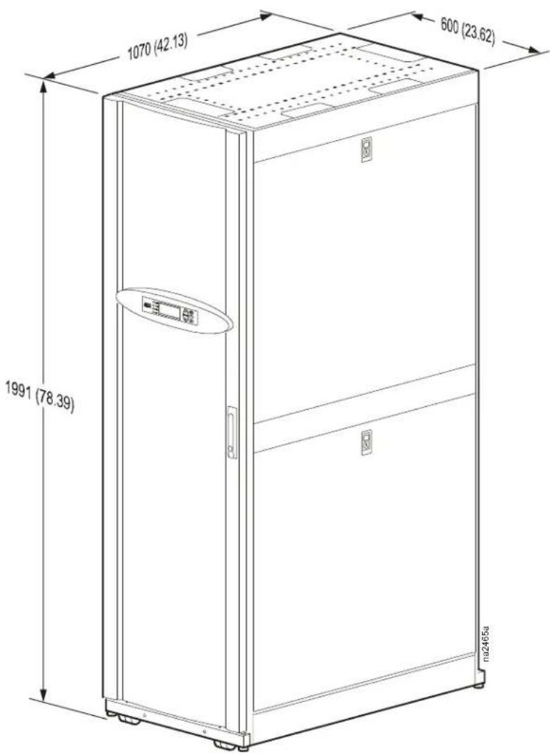
Dimensions are shown in mm (in).
SX to VX Height Adapter
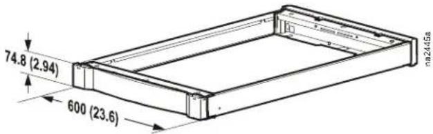
SX to 48U SX Height Adapter
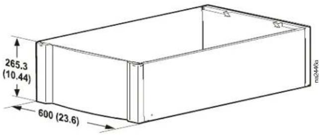
Dimensions are shown in mm (in).
Piping and Mechanical Connections
Chilled Water Piping Diagram
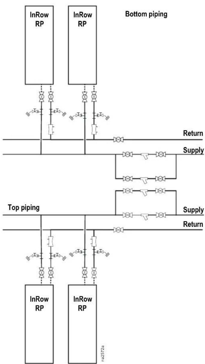
flowchart
graph TD
    subgraph Bottom piping
        A["InRow RP"] --> B["Return"]
        C["InRow RP"] --> D["Supply"]
        E["InRow RP"] --> F["Top piping"]
        G["InRow RP"] --> H["Return"]
    end
    style Bottom piping fill:#f9f,stroke:#333
    style Top piping fill:#ccf,stroke:#333
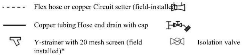
*Blow down may be installed on Y-strainer.
Top Chilled Water Piping Access (top view)

Note: Top or bottom entry can be chosen individually for each type of connection, i.e. power, condensate drain, humidifier water supply, chilled water supply and chilled water return. Top piping configuration will have the same valves and strainers as bottom piping configuration.
REAR—HOT AISLE
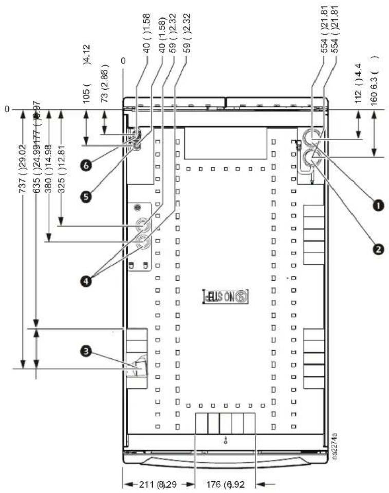
FRONT—COLD AISLE
Dimensions are shown in mm (in)
① Chilled water supply
② Chilled water return
③ Trough for communication cables
4 Power connections—dual feed
⑤ Humidifier supply
6 Condensate drain
Bottom Chilled Water Piping Access (bottom view, looking up)
REAR—HOT AISLE
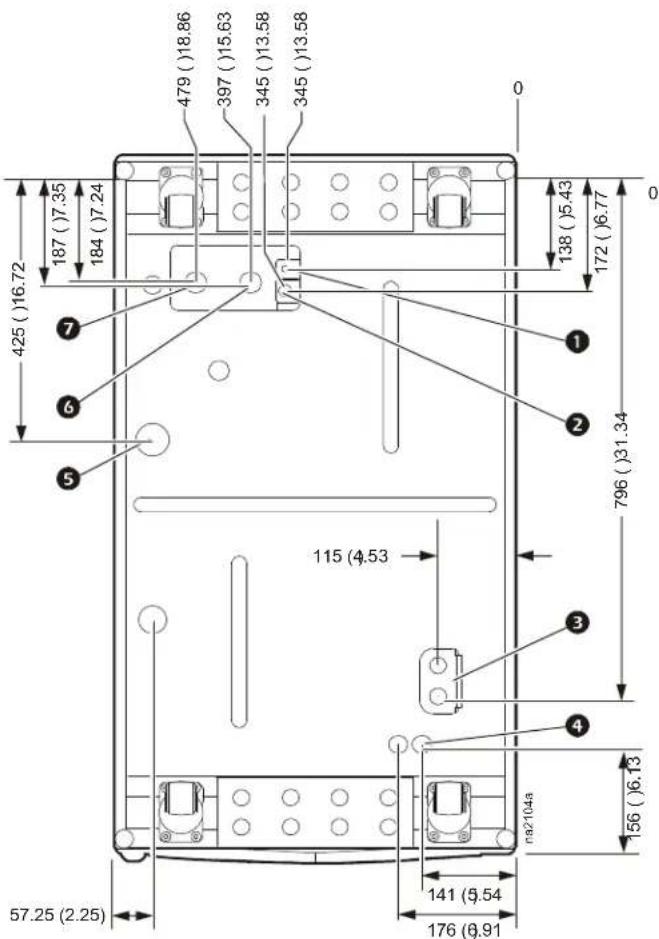
FRONT—COLD AISLE
Dimensions are shown in mm (in).
① Water supply to chiller
② Water supply from chiller
3 Condensate overflow
4 Communication connections—27.80 mm (1.09 in)
5 Power connections—dual feed
6 Condensate drain
7 Humidifier supply
Air-cooled Piping Diagram
Bottom piping Top piping
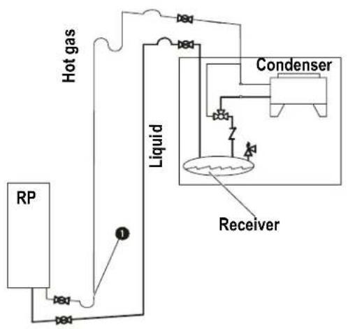
flowchart
graph TD
    A["Hot gas"] --> B["Liquid"]
    B --> C["Condenser"]
    C --> D["Receiver"]
    E["RP"] --> F["1"]
    style A fill:#f9f,stroke:#333
    style B fill:#ccf,stroke:#333
    style C fill:#cfc,stroke:#333
    style D fill:#fcc,stroke:#333
    style E fill:#ffc,stroke:#333
    style F fill:#cff,stroke:#333
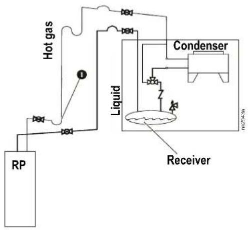
flowchart
graph TD
    RP["RP"] --> HotGas["Hot gas"]
    HotGas --> Liquid["Liquid"]
    Liquid --> Condenser["Condenser"]
    Condenser --> Receiver["Receiver"]
    Receiver --> Liquid
    style RP fill:#f9f,stroke:#333
    style HotGas fill:#ccf,stroke:#333
    style Liquid fill:#cfc,stroke:#333
    style Condenser fill:#fcc,stroke:#333
    style Receiver fill:#cff,stroke:#333

Note: Shutoff valves shown nearest to the condensers are not supplied by APC.
1
Pitch in direction of refrigerant flow; 4 mm per m (0.5-in per 10 ft)

Pressure relief valve
[NO TEXT]
Shutoff valves P-trap

[NO TEXT]
Head pressure control valve S-trap

N
Check valve Inverted P-trap

All lines are Type L copper tubing.

Note: Route piping through the top or bottom of the InRow RP.
Note: Trap the vertical discharge line every 6 m (20 ft) to ensure proper oil return.
Note: The maximum piping run is 61 m (200 ft) equivalent length. Size the piping pursuant to accepted refrigeration practice.

Warning: Do not install the air-cooled condenser below the indoor equipment. The condenser must be positioned above or at the same level as the equipment to ensure proper function.
Air-cooled Piping Access (top)
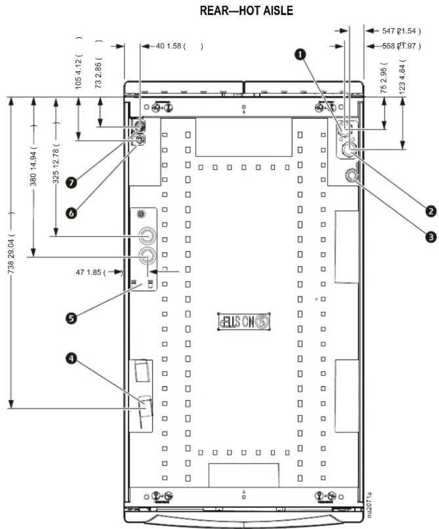
FRONT—COLD AISLE
① Refrigerant discharge line
② Refrigerant liquid line
3 Pressure relief valve discharge line
4 Trough for communication cables
5 Power connections
6 Humidifier water supply
7 Condensate drain
Dimensions are shown in mm (in).
Air-cooled Piping Access (bottom view, looking up)
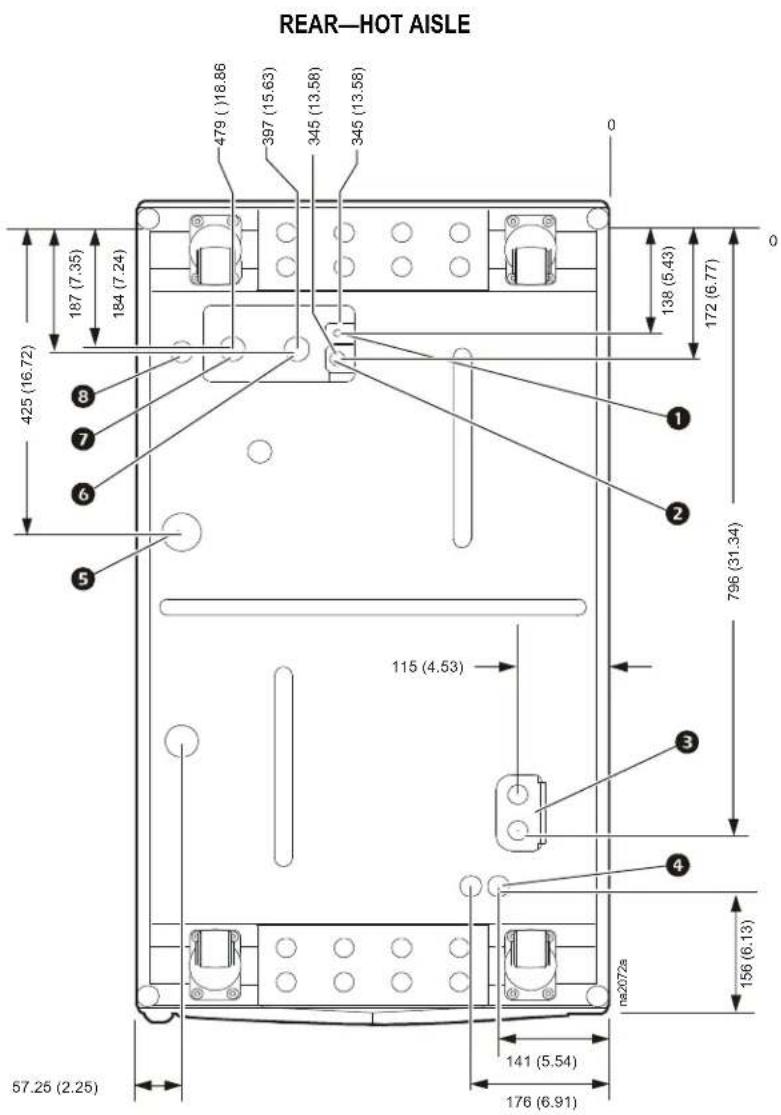
FRONT—COLD AISLE
① Pressure relief valve access—27.80 mm (1.09 in)
② Refrigerant liquid line
③ Refrigerant discharge line
4 Condensate overflow—50.00 mm (1.97 in)
5 Communication connections—27.80 mm (1.09 in)
6 Power connections
7 Condensate drain
8 Humidifier water supply
Dimensions are shown in mm (in).
Mechanical Data
| SKU | Ambient Temp | Sound Pressure (dbA)* | Sound Pressure (dbA) ** | Air Quantity | Tan Unit Connection Size Weight Capacity | ||||||
| 1/s (CFM) Qty. kW | Hot Gas | Liquid Kg (Lbs) | MBH/1F TD | kW/1C TD | |||||||
| ACCD75201 | 95 (35) | 67 | 62 | 4955 (10500) | 1 | 2.2 | 1 3/8 in | 1 3/8 in | 163 (360) | 8.8 | 4.6 |
| ACCD75202 | 105 (40) | 70 | 65 | 10383 (22000) | 2 | 4.4 | 1 5/8 in | 1 5/8 in | 290 (640) | 14.6 | 7.7 |
| ACCD75203 | 115 (46) | 72 | 68 | 14819 (31400) | 3 | 6.6 | 2 1/8 in | 2 1/8 in | 458 (1010) | 25.8 | 13.6 |
| ACCD75204 | 95 (35) | 67 | 62 | 4955 (10500) | 1 | 2.2 | 1 3/8 in | 1 3/8 in | 163 (360) | 8.8 | 4.6 |
| ACCD75205 | 105 (40) | 70 | 65 | 10383 (22000) | 2 | 4.4 | 1 5/8 in | 1 5/8 in | 290 (640) | 14.6 | 7.7 |
| ACCD75206 | 115 (46) | 72 | 68 | 14819 (31400) | 3 | 6.6 | 2 1/8 in | 2 1/8 in | 458 (1010) | 25.8 | 13.6 |
| ACCD75207 | 95 (35) | 54 | 51 | 5711 (12100) | 1 | 2.2 | 42 mm | 22 mm | 173 (381) | 17.6 | 9.3 |
| ACCD75208 | 105 (40) | 57 | 54 | 11940 (25300) | 2 | 2.2 | 42 mm | 28 mm | 307 (677) | 27.1 | 14.3 |
| ACCD75209 | 115 (46) | 57 | 55 | 11374 (24100) | 2 | 4.4 | 54 mm | 35 mm | 360 (792) | 48.2 | 25.4 |
* at 10 ft and 100% Fan Speed
** at 10 ft and Max Compressor Speed Selected Ambient Temp
Note: Specifications given for conditions at sea level.
Electrical Data
| SKU | Voltage | FLA | MCA | MOP |
| ACCD75201 | 208-2303 ph 60 Hz | 7.0 | 15.0 | 25 |
| ACCD75202 | 208-2303 ph 60 Hz | 14.0 | 20.0 | 35 |
| ACCD75203 | 208-2303 ph 60 Hz | 21.0 | 22.8 | 40 |
| ACCD75204 | 4603 ph 60 Hz | 3.5 | 15.0 | 15 |
| ACCD75205 | 4603 ph 60 Hz | 7.0 | 15.0 | 15 |
| ACCD75206 | 4603 ph 60 Hz | 10.5 | 15.0 | 20 |
| ACCD75207 | 4003 ph 50 Hz | 3.7 | N/A | N/A |
| ACCD75208 | 4003 ph 50 Hz | 7.4 | N/A | N/A |
| ACCD75209 | 4003 ph 50 Hz | 7.4 | N/A | N/A |
FLA = Full Load Amps
MCA = Minimum Circuit Amperes
MOP = Maximum Overcurrent Protection
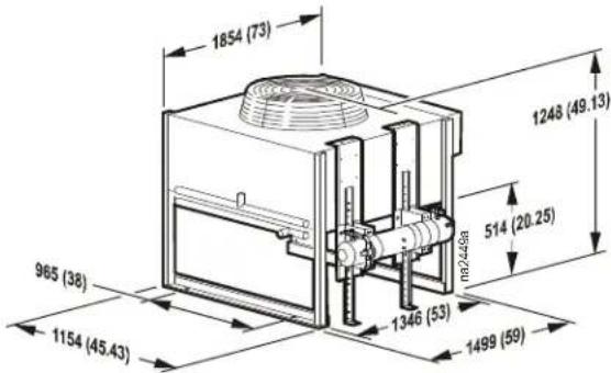
ACCD75201 and ACCD75204
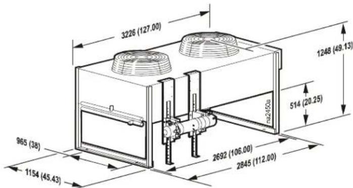
ACCD75202 and ACCD75205
ACCD75203 and ACCD75206
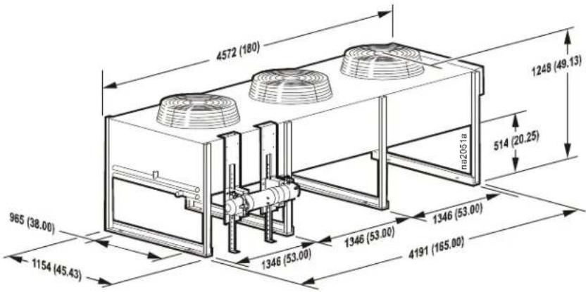
Dimensions are shown in mm (in).

Note: All condensers shown on this page have eight 22 mm (0.875 in) mounting holes on their lower rails.
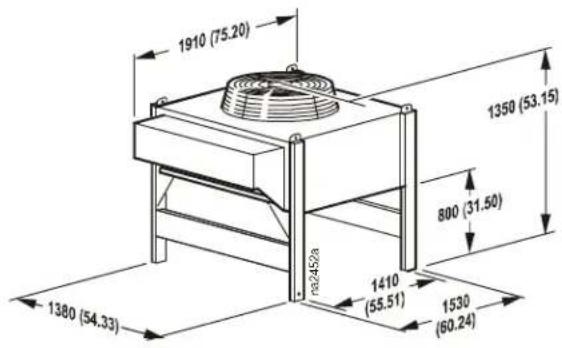
ACCD75207
ACCD75208 and ACCD75209
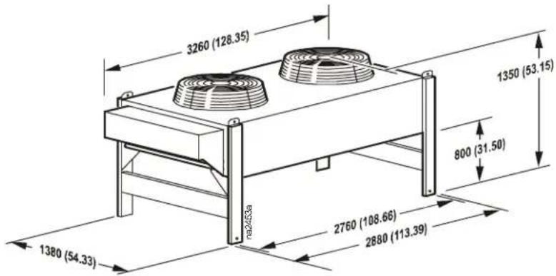
Dimensions are shown in mm (in). All condensers shown on this page have 16mm (0.63 in) mounting holes on each of their lower legs.
Air-cooled Condenser Features
Available in one to three fan configurations, APC offers air-cooled condensers with a vertical air discharge pattern. These condensers utilize variable speed EC motor technology for improved sound and energy performance.
60 Hz specific features:
- Constructed with aluminum housing
- Weatherproof control panel with a factory mounted door interrupt disconnect switch
50 Hz specific features:
- Constructed with painted galvanized steel

Note: A disconnect should be field-supplied based on MOP numbers.
PART 1 — GENERAL
1.01 SUMMARY
A. The environmental control system shall be designed specifically for precision temperature and humidity control applications. It will automatically monitor and control heating, cooling, humidifying, dehumidifying, and filtering functions for the conditioned space. The system shall be built to the highest quality engineering and manufacturing standards, and shall be floor mounted and configured for horizontal airflow, with draw-through air pattern, to provide uniform air distribution over the entire face of the coil.
1.02 DESIGN REQUIREMENTS
A. The system shall be as described in the following specification as manufactured by APC.
- Model: ____.
- Total net cooling capacity: kW (MBH).
- Sensible net cooling capacity: kW (MBH).
- Return air dry bulb temperature: ^ C ( ^ F) DB.
- Return air wet bulb temperature: ____ °C (°F) WB.
- Humidity: ____ % RH.
- Air Volume: ____ L/s (CFM).
- Humidifier capacity: ____ kg/hr (lbs/hr).
- Electrical supply: ____ V, ____ Hz.
1.03 SUBMITTALS
A. Submittals shall be provided with the proposal and shall include: capacity data, electrical data, physical data, electrical connection drawing, and piping connection drawing.
1.04 QUALITY ASSURANCE
A. The system shall be factory-tested prior to shipment. Testing shall include, but not be limited to: complete pressure and leak testing to ensure system integrity, "Hi-Pot" test, and controls calibration and settings. The system shall be NRTL listed, MCA, and electrical system shall be UL Listed to UL 1995 and CSA 22.2 No. 236.
1.05 WARRANTY
A. System parts shall be warranted for a period of 18 months from date of shipment and 12 months from startup.
PART 2 — PRODUCT
2.01 STANDARD COMPONENTS
A. CABINET CONSTRUCTION
- Exterior panels shall be 1.2 mm (18 gauge) steel. Front and rear exterior panels shall be 1.2 mm (18 gauge) perforated steel with 69.5% open free area, and equipped with a keyed lock to provide a means of securing access to the internal components of the unit.
- The frame shall be constructed of 1.5 mm (16 gauge) formed steel welded for maximum strength. All units shall provide maintenance from the front and rear, allowing units to be placed within a row of racks.
- All exterior panels and frame shall be powder coated for durability and attractive finish. Exterior frame and panel color shall have color values: L = 74.50 , a = -.53 , b = +8.20 .
- Units shall include casters and leveling feet to allow ease of installation in the row and provide a means to level the equipment with adjacent IT racks.
B. VARIABLE SPEED FAN ASSEMBLY
-
Variable Speed Fans: The unit is equipped with variable speed, electronically commutated, 400 mm backward incline fans complete with Inlet Volute.
-
Fan Protection: discharge finger guard. Outlet of the fan should include a cage type finger guard.
C. AUTOMATIC TRANSFER SWITCH (CHILLED WATER ONLY)
The unit shall be equipped with an automatic transfer switch (ATS). The ATS shall automatically switch from a main power supply to a secondary power supply in the event of a power outage without change in equipment operation. The ATS shall monitor the main power supply so that when the power is restored to the primary source it will automatically switch from the secondary source back to the main power source.
D. MAIN DISCONNECT SWITCH
- Unit shall be provided with Thermal-Magnetic circuit breakers with interrupt capacity ratings per UL489/CSA C22.2/IEC-947.
| Voltage kAIC | |
| 200-240V 50/60Hz | 50 |
| 380-415V 50Hz | 36 |
| 460-480V 60Hz | 22 |
-
Chilled Water: Units shall include main disconnect switches located on the E-panel in order to individually disconnect dual A-B power inputs.
-
Air-cooled: Units shall include a main disconnect switch located on the E-panel in order to disconnect power input.
-
A condenser disconnect shall be field-supplied.
E. MICROPROCESSOR CONTROLLER
-
Monitoring and Configuration: The display shall allow monitoring and configuration of the air conditioning unit through a menu-based control. Functions include status reporting, set-up, and temperature set points. Four LEDs report the operational status of the connected air conditioning unit.
-
Controls: The microprocessor controller shall come equipped with control keys to allow the user to navigate between menus, select items, and input alpha numeric information.
-
Alarms: The microprocessor controller shall activate a visible and audible alarm in the occurrence of the following events:
a. Cool Fail
b. Rack inlet temperature violation
c. Rack inlet temperature sensor fault
d. Air filter clogged
e. Air filter run hours exceeded
f. Filter DP sensor failure
g. Supply air sensor fault
h. Return air sensor fault
i. Supply air high temperature violation
j. Return air high temperature violation
k. Fan fault
- Fan run hours exceeded
m. Water detection fault
n. Condensate pump fault
o. Condensate run hours exceeded
p. Humidifier water conductivity high violation
q. Humidifier fault tolerance exceeded
r. Humidifier low water
s. Humidifier excessive output reduction
t. Humidifier drain fault
u. Humidifier cylinder full
v. Humidifier replace cylinder
w. Humidifier RS485 communication fault
x. Humidifier run hours violation
y. Humidity high/low violation
z. Supply humidity sensor fault
aa. Return humidity sensor fault
ab. Heater fault
ac. Heater run hours exceeded
ad. Heater interlock shutdown
ae. Group communication fault
af. Internal communication fault
ag. A-link isolation relay fault
ah. External communication fault
ai. Input contact fault
aj. Invalid supply setpoint
ak. Idle mode active
al. Coil fluid valve actuator fault
am. Fluid flow fault
an. Entering fluid temperature high violation
ao. Entering fluid temperature sensor fault
ap. Leaving fluid temperature sensor fault
aq. Power source failure
ar. Fluid calibration
as. High discharge pressure
at. Low suction pressure
au. High suction pressure
av. Compressor drive failure
aw. Compressor drive warning
ax. Compressor run hours violation
ay. Compressor drive RS485 communication fault
az. Excessive compressor cycling
ba. Air flow decreased while compressor off
bb. Suction pressure sensor failure
bc. Discharge pressure sensor failure
bd. High pressure switch active
be. Fan speed decreased to avoid high pressure (event only)
bf. Compressor speed decreased to avoid high pressure (event only)
bg. Compressor high pressure
bh. Oil return pump active
- Logging: The microprocessor controller shall log and display all available events. Each alarm log shall contain time/date stamp as well as operating conditions at the time of occurrence.
Controller shall display the run time hours for major components.
F. NETWORK MANAGEMENT CARD
The unit shall include a network management card to provide management through a computer network through TCP/IP. Management through the network should include the ability to change set points as well as view and clear alarms.
G. COOLING COIL AND CONDENSATE PAN
-
Chilled Water: Cooling coil shall use raised lance type corrugated aluminum fin and (12.7 mm (1/2 in) OD copper tube coils. Fin shall be a minimum of 0.0055 in thick. Tube wall shall be a minimum of 0.016 in thick. Coil tube sheets shall be a minimum 1.2 mm (18 gauge) G90 galvanized steel. Coil shall be rated for a maximum pressure of 2757.9 kPa (400 psig). Coil headers are equipped with drip plates in the bottom to route the condensate accumulating on the header tubes to the condensation pan. Coil is configured in a counterflow arrangement to optimize heat transfer efficiency.
-
Direct Expansion: Cooling coil shall use raised lance type corrugated aluminum fin and 12.7 mm (1/2 in) OD copper tube coils. Fin shall be a minimum of 0.0055 in thick. Tube wall shall be a minimum of 0.016 in thick. Coil end supports shall be a minimum 1.2 mm (18 gauge) G90 galvanized steel. Coil shall be rated for a maximum pressure of 3447.3 kPa (500 psig), and the coils are certified in accordance with UL207. Coil header is equipped with a drip plate in the bottom to capture and direct the condensation accumulating on the suction header tube to the drain pan. Coil has 6 circuits complete with brass distributor and copper distribution tubes.
H. VARIABLE SPEED COMPRESSOR / VFD ASSEMBLY (AIR-COOLED ONLY)
-
Compressor: The unit shall be configured with a variable speed reciprocating hermetic compressor using a matched VFD. As a result, the compressor speed can be varied through a range between 30 and 85 Hz to accommodate varying load conditions. VFD firmware is written to include oil return protection in cases where pipe velocities may drop to low speeds during low loading periods.
-
Compressor is electrically protected through the VFD.
-
Compressor utilizes a noise cap for noise reduction.
-
Sight glass provided for air cooled system oil charging.
I. 3-WAY MODULATING VALVE (CHILLED WATER ONLY)
- A floating point valve shall be microprocessor controlled to automatically direct the proper amount of chilled water in the cooling coil to maintain desired conditions. A shut-off valve located in the bypass line may be manually adjusted for 2-way flow if so desired.
- Three way control valve shall be rated for 300 WOG with brass body and stainless steel ball.
- Valve Actuator: Actuator shall be direct connect rotary floating point style actuator with potentiometer feedback, and should be capable of being replaced without disconnecting piping from the valve. Ability for manual operation is also provided.
J. CONDENSATE PUMP
Factory installed and wired condensate pump shall pump at 31.99 l/h (8.45 GPH) at 3.5 m (11.5 ft) of head. Pump shall have a dual position internal float and a reservoir made of polymeric materials to prevent corrosion.
K. FILTERS
- The standard filters shall be 30% efficient per ASHRAE Standard 52.1, UL Class 2 (MERV 8 per ASHRAE 52.2). Filters shall be EN779 G4 efficient. The 96 mm (3.75 in) deep, pleated filters shall be replaceable from the rear of the unit.
- The optional filter shall be 85% efficient per ASHRAE Standard 52.1 (MERV 13 per ASHRAE 52.2, EN779 F7).
L. HUMIDIFIER
Humidifier shall be able to modulate capacity. The humidifier shall be self-contained, steam-generating type, factory piped and wired, with disposable cylinder and automatic solid-state control circuit. Humidifier canisters shall be replaceable. The humidifier controller shall communicate directly to the microprocessor controller and provide complete status and control at the operator interface. Humidifier shall control flush cycling and conductivity via automated controls. Humidifier shall be capable of producing up to 3 kg (6.6 lb) of steam per hour.
M. ELECTRIC REHEAT
- Reheat elements shall be low watt density, wired for three-phase, loaded equally on all three phases and shall be electrically and thermally protected by both automatic and manual reset cutouts. Reheat capacity shall be 9 kW for chilled water and 6 kW for air-cooled.
- Reheat coils shall be stainless steel, fin tubular construction. Heater casing shall be 0.9 mm (20 gauge) G90 galvanized steel.
- Heater shall be provided with self-engaging electrical connectors upon installation. Heater with manually connected conductors are not acceptable.
N. TEMPERATURE AND HUMIDITY SENSORS
- Internal Temperature Sensors: Thermister temperature sensors shall be mounted behind the front and rear doors to provide control inputs based on supply and return air temperature. Sensor accuracy shall be within +/- 1 degree F accuracy.
- Remote Temperature Sensors: Three remote rack inlet temperature sensors shall be shipped with the unit to provide control input based on rack inlet temperature.
- Internal Humidity Sensors: Humidity sensors shall be mounted behind both the front and rear doors and shall provide control input based on humidity in supply air. Humidifier sensor shall be +/- 3% RH accuracy full scale.
- Water Temperature Sensors: Internal supply and return chilled water temperature sensors shall be installed into sealed wells. Wells are filled with thermal conducting heat transfer grease to provide accurate temperature sensors.
O. SELECTABLE TOP OR BOTTOM PIPING (CHILLED WATER ONLY)
- Pipe connections: The unit equipped with field connection from either the top or bottom of the unit. Unit connections shall be made internal to the unit.
- Pipe adapter: The unit shall include two pipe adapters that convert a 31.75 mm (1 1/4 in) NPT to a 31.75 mm (1 1/4 in) BSPT (manufactured in accordance with BS21). Pipe adapters shall ship loose with the unit for field installation where applicable.
P. SELECTABLE TOP OR BOTTOM PIPING (AIR-COOLED ONLY)
- Pipe connections: The unit is equipped with field connection from either top or bottom of the unit. Unit connections shall be made internal to the unit.
- Pipe adapters: The unit shall include 1-in Rotolock to sweat adapters and associated Teflon seals.
Q. FLOW METER
- Flow meter shall be factory piped inside the unit and connected to microprocessor controls to provide water flow rate through the unit. The microprocessor controller shall also use this information to provide total unit capacity out of the unit while in operation.
- Flow meter shall be stainless steel construction turbine type meter, compatible with glycol/water solutions up to 50%, with accuracy of 1.5% or better on range 5-50 GPM.
R. CABLE WATER DETECTOR (OPTIONAL)
- The optional leak detection sensing cable shall be shipped loose with the unit. If water or other conductive liquids contact the cable anywhere along its length, the main controller visually and audibly annunciates the leak.
- The optional detector shall be provided with a 6.1 m (20 ft) of cable. Cable may be cascaded up to 24.4 m (80 ft).
S. BRIDGE POWER CABLE TROUGH
- An overhead power distribution bridge, that sits between adjacent NetShelter racks and allows for removal of the unit without disrupting the overhead power cabling, is available as an accessory.
- Cable trough shall be constructed of 1.5 mm (16 gauge) cold rolled steel with a black powder coat finish.
T. BRIDGE DATA PARTITION
- An overhead cable distribution, that sits between adjacent Netshelter racks and allows for removal of the unit without disrupting overhead cabling, is available as an accessory.
- Data partition shall be constructed of 1.5 mm (16 gauge) cold rolled steel with a black powder coat finish.
U. COOLING FLUIDS
Chilled Water and solutions of propylene or ethylene glycol up to 50% may be used. Solutions of brine or other aqueous salt are NOT permitted.
V. FREEZE PROTECTION
Per ASHRAE Handbook Fundamentals 2001 21.5, a maximum of 30% ethylene glycol and 35% propylene glycol are needed for freeze protection. Please consult ASHRAE handbook for more details.
Guidelines for Installation
The InRow RP provides reliable, accurate temperature control of computer rooms, laboratories, and other environments that require close tolerance control. The unit incorporates the latest system design innovations to provide you with optimum efficiency, reliability, and accuracy of control.
The InRow RP unit will provide years of trouble-free service when installed and maintained by technically qualified personnel. For more detailed information, see the InRow RP Installation manual (990-2696 air-cooled and 990-2710 chilled water).
Room preparation
During the design of the room, consideration should be given to the following factors: ease of entry for the system, floor-loading factors, and accessibility of piping and wiring.
The room must be sealed with a vapor barrier to minimize moisture infiltration. Polyethylene film (plastic sheeting) is a good vapor barrier for ceiling and wall applications. Rubber- or plastic-based paints should be applied to concrete floors and walls. The room should be thoroughly insulated to minimize thermal loads and make-up air (if required) should be preconditioned to reduce additional temperature, filtration, and moisture loads.
Service access
At least 914 mm (36 in) of clear space must be left in the front and rear of the unit for routine service. In order to service the unit outside of the row, an area of 1219 mm (48 in) of clear space is required in the front and rear of the unit while it is in the row.
Receiving the unit
Your InRow RP unit has been tested and inspected prior to shipment. To ensure that you have received the unit in excellent condition, perform a careful inspection of the crating and the unit immediately upon receipt. Verify that all parts ordered were received as specified and that the unit is the correct size and voltage necessary to fulfill your environmental control needs. Report any damage discovered to the freight carrier. If necessary, contact the APC field service department for help in repairing or replacing damaged parts. While APC is not responsible for damage incurred in transit, we want to make sure that you have no undue delays in your system start-up. Please refer to the unpacking sheet for more information.
Rigging
The unit is manufactured with a formed steel frame for maximum strength and unit integrity. However, as with all electrical and mechanical equipment, you must take care with proper rigging of your unit.
When using a forklift to move the unit, use the shipping skid to protect the bottom of the unit. When using chains, cables, or rope to lift the unit, use spreader bars to prevent damage to the finished panels. Four threaded M10X16 holes are provided in the top of the frame to accommodate lifting eye bolts that can be utilized to lift the unit.
Condensate Drain
Condensation from the evaporator pan is collected and discharged by the condensate pump to a 3/8 in (10 mm) I.D. condensate line supplied with the unit. Additional condensate piping is required to route to building condensate system.
NOTE: Because of an ongoing program dedicated to product improvement, specifications are subject to revisions without notice. APC assumes no responsibility, and disclaims all liability for damages resulting from use of this information or for any errors or omissions.
APC Worldwide Customer Support
Customer support for this or any other APC product is available at no charge in any of the following ways:
- Visit the APC Web site to access documents in the APC Knowledge Base and to submit customer support requests.
- www.apc.com (Corporate Headquarters)
Connect to localized APC Web sites for specific countries, each of which provides customer support information. - www.apc.com/support/
Global support searching APC Knowledge Base and using e-support. - Contact the APC Customer Support Center by telephone or e-mail.
- Local, country-specific centers: go to www.apc.com/support/contact for contact information.
For information on how to obtain local customer support, contact the APC representative or other distributors from whom you purchased your APC product.
Entire contents copyright 2009 American Power Conversion Corporation. All rights reserved. Reproduction in whole or in part without permission is prohibited. APC, the APC logo, and InRow are trademarks of American Power Conversion Corporation. All other trademarks, product names, and corporate names are the property of their respective owners and are used for informational purposes only.
- American Power Conversion Legal Disclaimer
- Contents
- Overview 1
- Scalable Solution for Critical Environments ...... 2
- Standard Features.... 4
- Optional Features.... 6
- Microprocessor Controller 7
- InRow RP Models 9
- Performance Specifications 17
- Dimensional Data 27
- Piping and Mechanical Connections.... 29
- Air-Cooled Condensers 35
- Guide Specifications....38
- Guidelines for Installation 44
- Capacity
- Room Air Distribution
- Configuration
- Compliance Approval
- Chilled Water Standard Features
- Air-cooled Standard Features
- Accessories
- Scalable Solution for Critical Environments
- InRow Advantages
- Scalable for High Density
- Hot Aisle Containment System
- Standard Features
- Insulated Cabinet
- Variable Speed Fans
- Shutdown Input/Alarm Output
- Chilled Water Flow Meter
- 2-way/3-way Floating Point Valve (CW Only)
- Counterflow Cooling Coil/Condensate Pan
- Electric Reheat
- 30% ASHRAE 52.1 Filter
- Pipe Adapters (CW only)
- Pipe Adapters (Air-Cooled only)
- Selectable Top or Bottom Piping Connections
- Dual Position Float Condensate Management
- Network Management Card
- Bay Kit InRow RP/NetShelter SX
- Remote Temperature Sensors
- Humidifier
- Optional Features
- Cable Water Detector
- Network Cable
- 85% ASHRAE 52.1 Filter
- Power Trough
- Data Partition
- Height Adapters
- Flex Hose Piping Kits
- Microprocessor Controller
- Open Architecture
- Control Type
- Functions
- Logging
- Control
- Alarms
- Chilled Water Only Alarms
- Air-cooled Only Alarms
- Chilled Water Interior Components (back of unit)
- Air-cooled Interior Components (front of unit)
- Air-cooled Interior Components (back of unit)
- Chilled Water and Air-cooled User Interface Connections
- Chilled Water Electrical Panel
- Air-cooled Electrical Panel
- Performance Specifications
- Altitude Correction Factors for InRow Products
- Dimensional Data
- SX to VX Height Adapter
- SX to 48U SX Height Adapter
- Piping and Mechanical Connections
- Top Chilled Water Piping Access (top view)
- Bottom Chilled Water Piping Access (bottom view, looking up)
- Air-cooled Piping Diagram
- Air-cooled Piping Access (top)
- Air-cooled Piping Access (bottom view, looking up)
- FRONT—COLD AISLE
- ACCD75201 and ACCD75204
- ACCD75202 and ACCD75205
- ACCD75203 and ACCD75206
- ACCD75207
- ACCD75208 and ACCD75209
- Air-cooled Condenser Features
- PART 1 — GENERAL
- SUMMARY
- DESIGN REQUIREMENTS
- SUBMITTALS
- QUALITY ASSURANCE
- WARRANTY
- PART 2 — PRODUCT
- STANDARD COMPONENTS
- CABINET CONSTRUCTION
- VARIABLE SPEED FAN ASSEMBLY
- AUTOMATIC TRANSFER SWITCH (CHILLED WATER ONLY)
- MAIN DISCONNECT SWITCH
- MICROPROCESSOR CONTROLLER
- NETWORK MANAGEMENT CARD
- COOLING COIL AND CONDENSATE PAN
- VARIABLE SPEED COMPRESSOR / VFD ASSEMBLY (AIR-COOLED ONLY)
- 3-WAY MODULATING VALVE (CHILLED WATER ONLY)
- CONDENSATE PUMP
- FILTERS
- HUMIDIFIER
- ELECTRIC REHEAT
- TEMPERATURE AND HUMIDITY SENSORS
- SELECTABLE TOP OR BOTTOM PIPING (CHILLED WATER ONLY)
- SELECTABLE TOP OR BOTTOM PIPING (AIR-COOLED ONLY)
- FLOW METER
- CABLE WATER DETECTOR (OPTIONAL)
- BRIDGE POWER CABLE TROUGH
- BRIDGE DATA PARTITION
- COOLING FLUIDS
- FREEZE PROTECTION
- Guidelines for Installation
- Room preparation
- Service access
- Receiving the unit
- Rigging
- Condensate Drain
- APC Worldwide Customer Support
Brand : APC
Model : Condenser 2 EC Fan
Category : Computer Cooling Component