
SNC-Z20N - Security Camera SONY - Free user manual and instructions
Find the device manual for free SNC-Z20N SONY in PDF.


| Product Type | Security Camera (Network Camera) |
| Brand | Sony |
| Model | SNC-Z20N |
| Image Sensor | 1/4-type CCD |
| Effective Pixels | Approx. 380,000 |
| Resolution | 736 x 480, 640 x 480, 320 x 240, 160 x 120 |
| Optical Zoom | 18x |
| Electronic Zoom | 12x (total 216x) |
| Frame Rate | Up to 30 fps (NTSC) |
| Network Interface | Ethernet (10/100 Base-T), Wireless LAN (optional) |
| Video Output | BNC (composite video) |
| I/O Ports | Alarm input/output, sensor input, serial port (RS-232C/RS-422/RS-485) |
| Storage | Built-in flash memory (approx. 8 MB), ATA memory card slot |
| Day/Night Mode | Yes (Auto, Manual, Timer) |
| Activity Detection | Yes (built-in) |
| Alarm Functions | FTP, email, alarm out, alarm buffer |
| Supported Protocols | HTTP, FTP, SMTP, SNMP, DHCP, ARP |
| Power Supply | 12 V DC or PoE (IEEE 802.3af) |
| Power Consumption | Approx. 10 W |
| Dimensions (W x H x D) | Approx. 140 x 140 x 160 mm |
| Weight | Approx. 1.1 kg |
| Operating Temperature | 0 °C to 40 °C (32 °F to 104 °F) |
| Operating Humidity | 20% to 80% (non-condensing) |
| Included Accessories | Installation Manual, CD-ROM (setup program, user guide) |
Frequently Asked Questions - SNC-Z20N SONY
User questions about SNC-Z20N SONY
0 question about this device. Answer the ones you know or ask your own.
Ask a new question about this device
Download the instructions for your Security Camera in PDF format for free! Find your manual SNC-Z20N - SONY and take your electronic device back in hand. On this page are published all the documents necessary for the use of your device. SNC-Z20N by SONY.
USER MANUAL SNC-Z20N SONY
How to Use This User's Guide .... 5
Operating the Camera
Logging in to Homepage — Welcome Page ...... 6
Logging in as a User 6
Logging in as Administrator 6
About Viewers ...... 7
Configuration of Main Viewer Page 8
Menu Section 8
Image Control Section 8
Monitor Image Section 9
Zoom Bar 9
Controlling the Monitor Image 9
Operating the Camera from the Image Control
Section 10
Zooming 10
Focusing 10
Operating the Camera from the Monitor Image
11
Zooming Using the Center Wheel of the Mouse 11
Zooming Using the Zoom Bar 11
Controlling the Application Manually ..... 11
Sending a Still Image File to an FTP Server .... 11
Sending a Still Image via E-mail 11
Recording a Still Image on an ATA Memory Card or the Built-in Memory of the Camera ...... 12
Controlling Alarm Output 12
Selecting the Day/Night Mode 12
Capturing a Monitor Image 12
Administrating the Camera
Configuration of Administrator Menu Page ..... 13
Configuring the System — System setting Page 14
System setting Section 14
Date time setting Section 16
Initialization Section 17
Setting the Camera — Camera setting Page .... 17
Camera setting Section 17
Day/Night setting Section 20
Camera control mode setting Section 21
Configuring the Network
— Network setting Page ...... 21
Wired LAN setting Section 21
Wireless LAN setting Section 22
HTTP port setting Section 23
Notifying the IP Address
— Dynamic IP address notification Section ...24
Setting the User — User setting Page ......25
Setting the Security — Security setting Page ....26
Activating/Deactivating the Security Function — Security usage setting Page ......26
Setting the Security Function —Securing setting Page ....26
Sending Images to FTP Server
— FTP client setting Page ......27
Activating/Deactivating the FTP Client Function — FTP client usage setting Page .....27
Setting the FTP Client Function — FTP client setting Page ....27
Alarm mode setting Section 28
Periodical sending mode setting Section .....29
Operating the Digest Viewer ....30
Downloading Images from the Camera
— FTP server setting Page ....31
Activating/Deactivating the FTP Server Function — FTP server usage setting Page ....31
Setting the FTP Server Function — FTP server setting Page ....31
Sending an Image via E-mail
— SMTP setting Page ....32
Activating/Deactivating the SMTP Function — SMTP usage setting Page ....32
Setting the SMTP Function — SMTP setting Page ....32
Alarm mode setting Section 33
Periodical sending mode setting Section .....33
Setting the Alarm Out 1 or 2
— Alarm out 1 or 2 setting Page ....34
Activating/Deactivating the Alarm Out 1 Function — Alarm out 1 usage setting Page ....34
Setting the Alarm Out 1 Function — Alarm out 1 setting Page ....34
Alarm mode setting Section ....34
Timer mode setting Section 35
Recording Images in Memory
— Image memory setting Page ....35
Activating/Deactivating the Image Memory Function — Image memory usage setting Page 35
Recording an Image in the Selected Memory — Image memory setting Page ....36
Alarm mode setting Section 37
Periodical recording mode setting Section .....37
Directory Structure of Image Memory ....38
Setting the Alarm Buffer
— Alarm buffer setting Page ....39
Communicating Data via Serial Port
— Serial setting Page ....39
Setting the Schedule — Schedule setting Page ..40
Setting the Activity Detection Function
— Activity detection setting Page ....41
Setting the Activity Detection Area 41
Showing the Pop-up — Pop-up setting Page ..... 42
Others
Using the Supplied Setup Program .... 43
Assigning the IP Address Using the Setup Program 43
Changing the Communication Bandwidth ..... 45
Setting the Date and Time 45
Rebooting the Camera 45
Assigning the IP Address to the Camera Using
ARP Commands 46
Using the SNMP 47
-
Inquiry Commands ...... 47
-
Setting Commands 47
Storing an HTML File in the Built-in Flash
Memory 49
When using Windows XP Service Pack 2 ..... 51
When using Windows Vista 53
Index 56
Overview
- You should keep in mind that the images or audio you are monitoring may be protected by privacy and other legal rights, and the responsibility for making sure you are complying with applicable laws is yours alone.
- Access to the images and audio is protected only by a user name and the password you set up. No further authentication is provided nor should you presume that any other protective filtering is done by the service. Since the service is Internet-based, there is a risk that the image or audio you are monitoring can be viewed or used by a third-party via the network.
- SONY IS NOT RESPONSIBLE, AND ASSUMES ABSOLUTELY NO LIABILITY TO YOU OR ANYONE ELSE, FOR SERVICE INTERRUPTIONS OR DISCONTINUATIONS OR EVEN SERVICE CANCELLATION. THE SERVICE IS PROVIDED AS-IS, AND SONY DISCLAIMS AND EXCLUDES ALL WARRANTIES, EXPRESS OR IMPLIED, WITH RESPECT TO THE SERVICE INCLUDING, BUT NOT LIMITED TO, ANY OR ALL IMPLIED WARRANTIES OF MERCHANTABILITY, FITNESS FOR A PARTICULAR PURPOSE, OR THAT IT WILL OPERATE ERROR-FREE OR CONTINUOUSLY.
- Security configuration is essential for wireless LAN. Should a problem occur without setting security, or due to the limitation of the wireless LAN specifications, SONY shall not be liable for any damage.
• Always make a test recording, and verify that it was recorded successfully. SONY WILL NOT BE LIABLE FOR DAMAGES OF ANY KIND INCLUDING, BUT NOT LIMITED TO, COMPENSATION OR REIMBURSEMENT ON ACCOUNT OF FAILURE OF THIS UNIT OR ITS RECORDING MEDIA, EXTERNAL STORAGE SYSTEMS OR ANY OTHER MEDIA OR STORAGE SYSTEMS TO RECORD CONTENT OF ANY TYPE.
• Always verify that the unit is operating properly before use. SONY WILL NOT BE LIABLE FOR DAMAGES OF ANY KIND INCLUDING, BUT NOT LIMITED TO, COMPENSATION OR REIMBURSEMENT ON ACCOUNT OF THE LOSS OF PRESENT OR PROSPECTIVE PROFITS DUE TO FAILURE OF THIS UNIT, EITHER DURING THE WARRANTY PERIOD OR AFTER EXPIRATION OF THE WARRANTY, OR FOR ANY OTHER REASON WHATSOEVER. - If you lose data by using this unit, SONY accepts no responsibility for restoration of the data.
NOTICE TO USERS
© 2003 Sony Corporation. All rights reserved. This manual or the software described herein, in whole or in part, may not be reproduced, translated or reduced to any machine readable form without prior written approval from Sony Corporation.
SONY CORPORATION PROVIDES NO WARRANTY WITH REGARD TO THIS MANUAL, THE SOFTWARE OR OTHER INFORMATION CONTAINED HEREIN AND HEREBY EXPRESSLY DISCLAIMS ANY IMPLIED WARRANTIES OF MERCHANTABILITY OR FITNESS FOR ANY PARTICULAR PURPOSE WITH REGARD TO THIS MANUAL, THE SOFTWARE OR SUCH OTHER INFORMATION. IN NO EVENT SHALL SONY CORPORATION BE LIABLE FOR ANY INCIDENTAL, CONSEQUENTIAL OR SPECIAL DAMAGES, WHETHER BASED ON TORT, CONTRACT, OR OTHERWISE, ARISING OUT OF OR IN CONNECTION WITH THIS MANUAL, THE SOFTWARE OR OTHER INFORMATION CONTAINED HEREIN OR THE USE THEREOF.
Sony Corporation reserves the right to make any modification to this manual or the information contained herein at any time without notice.
The software described herein may also be governed by the terms of a separate user license agreement.
"Memory Stick" is a trademark of Sony Corporation. Microsoft, Windows, Internet Explorer and MS-DOS are registered trademarks of Microsoft Corporation in the United States and/or other countries.
Java is a trademark of Sun Microsystems, Inc. in the United States and other countries.
MMX and Pentium are registered trademarks of Intel Corporation or its subsidiaries in the United States and other countries.
Jeode is a registered trademark or trademark of Insignia Solutions, Inc. in the United States and other countries.
All other company and product names are trademarks or registered trademarks of the respective companies or their respective makers.
Phenomena Specific to CCD Image Sensors
The following phenomena that may appear in images are specific to CCD (Charge Coupled Device) image sensors. They do not indicate malfunctions.
White flecks
Although the CCD image sensors are produced with high-precision technologies, fine white flecks may be generated on the screen in rare cases, caused by cosmic rays, etc.
This is related to the principle of CCD image sensors and is not a malfunction.
The white flecks especially tend to be seen in the following cases:
- when operating at a high environmental temperature
- when you have raised the gain (sensitivity)
- when using the slow shutter
Vertical smear
When an extremely bright object, such as a strong spotlight or flashlight, is being shot, vertical tails may be produced on the screen, or the image may be distorted.
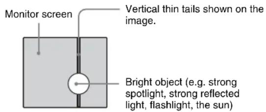
Aliasing
When fine patterns, stripes, or lines are shot, they may appear jagged or flicker.
How to Use This User's Guide
This User's Guide explains how to operate the SNC-Z20N/Z20P Network Camera from a computer.
The User's Guide is written to be read on the computer display.
As this section gives tips on using the User's Guide, read it before you operate the camera.
Jumping to the related page
When you read the User's Guide on the computer display, click on the sentence to jump to the related page.
Software display examples
Note that the displays shown in the User's Guide are explanatory examples. Some displays may be different from the ones which appear as you operate the application software.
Printing the User's Guide
Depending on your system, certain displays or illustrations in the User's Guide, when printed out, may differ from those as portrayed on your screen.
Installation Manual (printed matter)
The supplied Installation Manual describes the names and functions of parts and controls of the Network Camera, connecting examples and how to set up the camera. Be sure to read the Installation Manual before operating.
Operating the Camera
The Operating the Camera section explains how to monitor the image from the camera using the Web browser. Use Internet Explorer as the Web browser. For setting the camera, see “Administrating the Camera” on page 13.
Logging in to Homepage — Welcome Page
Logging in as a User
1 Start the web browser on the computer and type the IP address of the camera you want to monitor.

The welcome page of Network Camera SNC-Z20 is displayed.
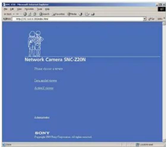
2 Click to select the viewer. You can select the viewer from among Java applet viewer, ActiveX viewer whichever is suitable for your system environments and usage. For details, see “About Viewers” on page 7. When you have selected the viewer, the main viewer page appears (see page 8).
Note
To operate the welcome page correctly, set the security level of the Internet Explorer to Medium or lower, as follows:
1 Select Tool from the menu bar of Internet Explorer, then select Internet Options and Security tab in sequence.
2 Click the Internet icon (when using the camera via the Internet) or Local intranet icon (when using the camera via a local network).
3 Set the slider to Medium or lower. (If the slider is not displayed, click Default Level.)
When using antivirus software in the computer
- When you use antivirus software in your computer, the camera performance may be reduced, for example, the frame rate for displaying the image may lower.
- The Web page displayed when you log in the camera uses Java Script. The display of the page may be affected if you use antivirus software in your computer.
Logging in as Administrator
If you log in the camera as the Administrator, you can perform all the settings provided with the software. The Administrator may be logged in at any time, regardless of the number of the users being accessed.
1 Click Administrator on the welcome page. The login page appears.
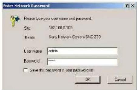
2 Enter the user name and password for Administrator, then click OK. The user name “admin” and the password “admin” are set at the factory for the Administrator. You can change them on the User setting page in the Administrator menu (see page 25).
The welcome page is changed to that for Administrator.
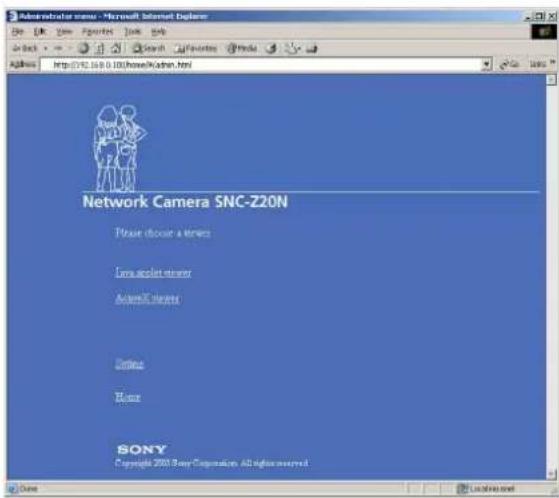
3 Select the viewer.
You can select the viewer from among Java applet viewer, ActiveX viewer whichever is suitable for your system environments and usage. For details, see "About Viewers" on page 7. When you have selected the viewer, the main viewer page appears (see page 8).
Other functions on the welcome page for Administrator
Setting
Click to display the Administrator menu (see page 13).
Home
Click to return to the normal welcome page.
About Viewers
You can select one of the following three viewers.
Java applet viewer
It displays the main viewer page using Java. The frame rate is lower than the ActiveX viewer.
The Java applet viewer operates only when Java is installed and Java (Sun) is enabled. If it does not operate correctly, check whether the effective Java version has been installed successfully and Java (Sun) is enabled.
Effective version: Java Plug-in Ver. 1.6.0_01
To check the Java version
Select Tools from the menu bar of Internet Explorer, then select Internet Options and click the Advanced mode tab. Check whether the version of Java displayed for Java (Sun) is one of the versions specified above. If
Java (Sun) is not displayed, it means that Java is not installed. You need to install Java.
To enable Java Plug-in
Check "Use JRE 1.6.0_01 for
To install Java Plug-in
Download Java 2 Runtime Environment, Standard Edition (JRE) from the website of Sun Microsystems, Inc., and install it by following the instructions on the installer.
ActiveX viewer
It displays the main viewer page using ActiveX. With this viewer, you can display images at a high frame rate and use all the functions provided with this software.
When you log in the camera using Internet Explorer for the first time, the Security Warning appears. Click Yes and install ActiveX Control.
Notes
- If you cannot display the image on Windows NT4.0 or Windows 98, install MFC42DLL Version Up Tool stored in the supplied CD-ROM.
- If Automatic configuration is enabled in the Local Area Network (LAN) Settings of Internet Explorer, the image may not be displayed. In that case, disable Automatic configuration and set the Proxy server manually. For the setting of the Proxy server, consult your network administrator.
- When you install ActiveX Control, you should be logged in to the computer as Administrator.
- When you are using Windows XP Service Pack 2 or Windows Vista, the information bar or "Security Warning" may appear as you click Enter. For details, see "Installing ActiveX Control" in see "When using Windows XP Service Pack 2" on page 51 or "Installing ActiveX Control" in see "When using Windows Vista" on page 53.
Tip
Every page of this software is optimized as display character size Medium for Internet Explorer.
Configuration of Main Viewer Page
When you select the viewer, the main viewer page is displayed.
This section briefly explains the functions of the parts and controls on the main viewer page. For a detailed explanation on each part or control, see the specified pages.
Main viewer page
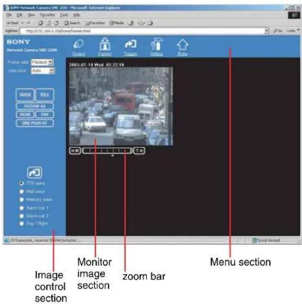
Menu Section
The available functions are limited by user access right. You can change user access right on the User setting page (see page 25).

Control
Displays the camera control parts on the image control section. (See "Operating the Camera from the Image Control Section" on page 10.)
User access right Level 2 to Level 4 is required for this function.
Capture
Captures a still image shot by the camera and stores it in the computer. (See “Capturing a Monitor Image” on page 12.)

Trigger
Displays the trigger control parts on the image control section.
By clicking the trigger button, you can control various applications manually. (See "Controlling the Application Manually" on page 11.)
User access right Level 3 or Level 4 is required for this function.

Setting
Displays the Administrator menu. (See "Configuration of Administrator Menu Page" on page 13.)
User access right Level 4 is required for this function.

Home
Displays the Welcome page.
Image Control Section
Frame rate
Selects the frame rate to transmit images.
See "Selecting the frame rate" on page 9.
View size
Selects the image size to be displayed. See "Selecting the view size" on page 9.
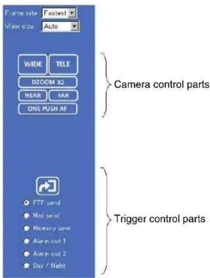
Camera control parts
These parts are displayed when you click Control on the menu section. You can operate the camera using these parts.
See “Operating the Camera from the Image Control Section” on page 10.
Trigger control parts
These parts are displayed when you click Trigger on the menu section. You can output a trigger using these parts. See “Controlling the Application Manually” on page 11.
Monitor Image Section
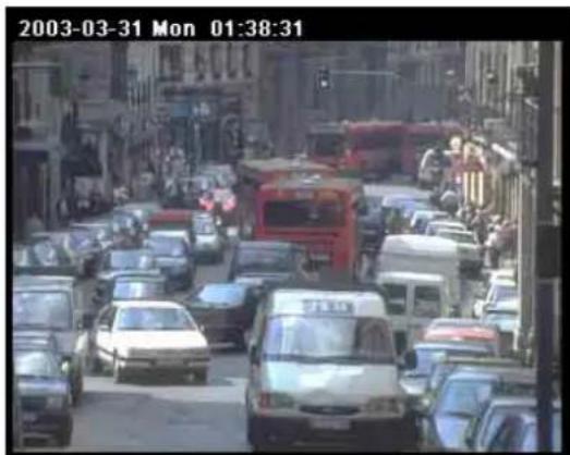
The image shot by the camera is shown here. Click Control on the menu section to allow zooming of the camera from the monitor image. See “Operating the Camera from the Monitor Image” on page 11.
Zoom Bar

The zoom bar is displayed when you click Control on the menu section. You can operate the zoom using the zoom bar.
See "Zooming Using the Zoom Bar" on page 11.
Controlling the Monitor Image
You can control the monitor image from the image control section on the main viewer page.
Image control section
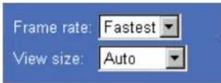
Selecting the frame rate
Click the down-arrow button in the Frame rate box and select the frame rate with which the images are transmitted, from the drop-down list.
You can select the frame rate from among the following: SNC-Z20N:
1, 2, 3, 4, 5, 6, 8, 10, 15, 20, 25, Fastest SNC-Z20P:
1, 2, 3, 4, 5, 6, 8, 12, 16, 20, Fastest
The numbers indicate “FPS” (the number of frames transmitted per second).
With Fastest, the camera transmits the maximum number of frames possible for the connected line. The maximum frame rate is 30 FPS for the SNC-Z20N and 25 FPS for the SNC-Z20P.
Note
The frame rate options indicate the maximum number of frames that can be transmitted. The number of frames actually transmitted may vary depending on the network environments and camera settings (image size and image quality settings).
Selecting the view size
Click the down-arrow button in the View size box and select the view size from the drop-down list.
You can select the view size from among the following: Auto, 640 × 480, 320 × 240, 160 × 120
Auto is determined by the image size specified with Image size on the Camera setting page (see page 17).
Operating the Camera from the Image Control Section
You can operate the camera from the image control section on the main viewer page. For this function, user access right Level 2 to Level 4 is required (see page 25).
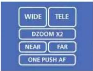
Click ☐ Control on the menu section to display the camera control parts.
Image control section (camera control parts)
flowchart
graph TD
    A["WIDE"] --> B["DZOOM X2"]
    C["TELE"] --> B
    D["NEAR"] --> E["FAR"]
    F["ONE PUSH AF"] --> E
    B --> G["..."]
Zooming
WIDE
Click to zoom out.
TELE
Click to zoom in.
Note
You can change the operation mode of the zooming using the TELE/WIDE buttons from the Camera control mode setting section on the Camera setting page (see page 21). When you have changed the operation mode, click Control on the menu section to update the operation mode setting on the image control section.
DZOOM X2
When the Zoom mode menu on the Camera setting page is set to Optical only, clicking this button operates the electronic ×2 zoom.
The button name changes to DZOOM x 1.
DZOOM X1
When the Zoom mode menu on the Camera setting page is set to Optical only, this button is displayed while the electronic ×2 zoom is operating. Clicking this button cancels the electronic ×2 zoom.
The button name changes to DZOOM x 2.
About the zoom range
When the Zoom mode menu on the Camera setting page is set to Full (see page 19), you can operate high-magnification zoom, optical zoom of × 18 and electronic zoom of × 12, giving × 216 in total. The electronic zoom will operate after the optical zoom.
When the Zoom mode menu is set to Optical only, only optical zoom of × 18 can operate. In this case, you can use an electronic zoom of × 2 by clicking the DZOOM x 2 button. To cancel the electronic zoom, click DZOOM x 1.
Note
When you have changed the Zoom mode menu on the Camera setting page, click the Control button on the menu section to update the zoom mode setting on the image control section.
Focusing
The focus is automatically adjusted when the Focus mode menu on the Camera setting page is set to Auto (see page 19). When you set it to Manual, you can adjust the focus manually from the image control section, or adjust it with a push of the button.
NEAR
FAR
Adjust the focus manually by clicking the two buttons alternately.
ONE PUSH AF
Click this button to adjust the focus instantly.
Notes
- When you have changed the Focus mode menu on the Camera setting page, click the Control button on the menu section to update the focus mode setting on the image control section.
- You can change the operation mode of the manual focusing using the NEAR/FAR buttons from the Camera control mode setting section on the Camera setting page (see page 21). When you have changed the operation mode, click Control on the menu section to update the operation mode setting on the image control section.
Operating the Camera from the Monitor Image
You can operate zooming of the camera by clicking the mouse on the monitor image. Zooming is also operative using the zoom bar under the monitor image.
For this function, user access right Level 2 to Level 4 is required (see page 26).
To enable this function, click Control on the menu section.
Zooming Using the Center Wheel of the Mouse
When you use the ActiveX viewer, you can zoom in/out using the center wheel of the mouse. Turn the center wheel forward to zoom in, and backward (toward you) to zoom out.
Notes
- This function does not operate when you use a mouse without the center wheel.
- This function does not operate on the Java applet viewer.
- This function may not operate correctly depending on your system environments.
Zooming Using the Zoom Bar
You can operate the optical zoom ( ×1 to ×18 ) and the electronic zoom ( ×1 to ×12 ) using the zoom bar displayed under the monitor image.
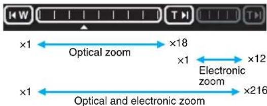
Click room in to the TELE end (×18).
Click ☑ zoom in to the TELE end (×216 with the optical and electronic zoom).
Click ☐ woom out to the WIDE end (×1).
When you click on the zoom bar, the camera zooms in or out corresponding to the clicked position, and ▲ moves to the clicked position.
Notes
- When the Zoom mode menu on the Camera setting page is set to Optical only, only the optical zoom bar appears.
- When you have changed the Zoom mode menu on the Camera setting page, click the Control button on the menu section to update the Zoom mode setting on the zoom bar.
Controlling the Application Manually
You can send an image or output a trigger to control the alarm output, using the image control section on the main viewer page.
For this function, user access right Level 3 or Level 4 is required (see page 25).
Click Trigger on the menu section to display the trigger control parts.
Image control section (trigger control parts)
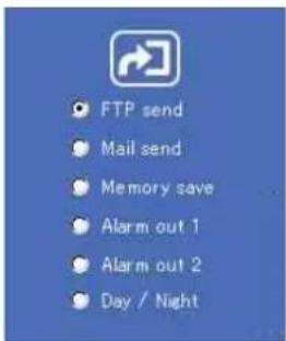
Sending a Still Image File to an FTP Server
If you select FTP send and click the current still image is captured and the captured image file is sent to the FTP server.
To use this function, you need to select the Use FTP client function option and the Manual mode on the FTP client setting page.
For details, see “Sending Images to FTP Server — FTP client setting Page” on page 27.
Sending a Still Image via E-mail
If you select Mail send and click 📋, the current still image is captured and an E-mail with the captured image file attached is sent to the E-mail address(es) specified on the SMTP setting page.
To use this function, you need to select the Use SMTP function option and the Manual mode on the SMTP setting page.
For details, see “Sending an Image via E-mail — SMTP setting Page” on page 32.
Recording a Still Image on an ATA Memory Card or the Built-in Memory of the Camera
If you select Memory save and click the current still image is captured and stored in the memory specified on the Image memory setting page.
To use this function, you need to select the Use image memory function option and the Manual mode on the Image memory setting page.
For details, see "Recording Images in Memory — Image memory setting Page" on page 35.
Controlling Alarm Output
If you select Alarm out 1 or Alarm out 2 and click 📄, you can control alarm out 1 or alarm out 2 of the I/O port on the camera manually. Each click switches the relay between short-circuit and open alternately.
To use this function, you need to select the Use alarm out 1 (or 2) function option and the Manual mode on the Alarm out 1 or Alarm out 2 setting page.
For details, see "Setting the Alarm Out 1 or 2 — Alarm out 1 or 2 setting Page" on page 34.
For the connection of peripheral devices to the Alarm out of the I/O port, see the supplied Installation Manual.
Selecting the Day/Night Mode
If you select Day/Night and click 📋, you can select the Day/Night mode. Each click switches between the day mode and night mode.
To use this function, you need to select the Day/Night mode menu on the Camera setting page to Manual.
For details, see "Setting the Camera — Camera setting Page" on page 20.
Capturing a Monitor Image
If you click the Capture button on the menu section, the current still image is captured and displayed on the monitor image section.
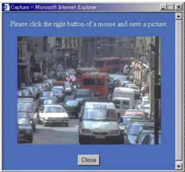
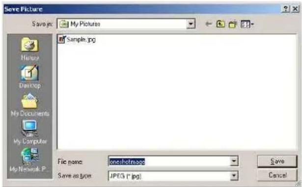
To save the captured image
Right-click on the monitor image and select Save As from the menu. Then, the Save Picture dialog appears. Type the file name and specify the destination to which the image file is to be stored, and click Save. The image is saved in the JPEG format.
Administrating the Camera
The Administrating the Camera section explains how to set the functions of the camera by the Administrator. For monitoring the camera image, see “Operating the Camera” on page 6.
Configuration of Administrator Menu Page
The Administrator menu page is displayed when the Administrator having Level 4 access right selects Setting on the welcome page for Administrator, or when the Setting button on the menu section of the main viewer page is clicked.
![Setting name - Microsoft Internet Explorer File Edit View Favorites Tools Help Back Search User Search User Search User Search User Search User Search User Search User Search User Search User Search User Search User Search User Search User Search User Search User Search User Search User Search User Search User Search User Search User Search User Search User Search User Search User Search U.S. (192) [105] [107] [Home] [Machon, USA] [My] Basic System Camera Network User Security Application FTP class FTP series SMTP Alerts out 1 Alerts out 2 Inner memory Alerts better Serial Schedule Activity detection Portfolio Home SONY Network Camera SNC-C268 Done](/content/2026/05/920516/images/0bc32307441151c3223cdc33bae3a7ab735e734bbebc025f3bc7e66bf3cd2ded.jpg)
The Administrator menu consists of the Basic menu and the Application menu. The Basic menu is used for basic settings of the camera, and the Application menu is used for setting various applications according to individual. Click on each menu name to display its setting page.
Basic menu
System
Displays the System setting page. See “Configuring the System — System setting Page” on page 14.
Camera
Displays the Camera setting page. See “Setting the Camera — Camera setting Page” on page 17.
Network
Displays the Network (Ethernet) setting page. See “Configuring the Network — Network setting Page” on page 21.
User
Displays the User setting page. See “Setting the User — User setting Page” on page 25.
Security
Displays the Security setting page. See “Setting the Security — Security setting Page” on page 26.
Application menu
FTP client
Displays the FTP client setting page. See “Sending Images to FTP Server — FTP client setting Page” on page 27.
FTP server
Displays the FTP server setting page. See “Downloading Images from the Camera — FTP server setting Page” on page 31.
SMTP
Displays the SMTP setting page. See “Sending an Image via E-mail — SMTP setting Page” on page 32.
Alarm out 1
Displays the Alarm out 1 setting page. See “Setting the Alarm Out 1 or 2 — Alarm out 1 or 2 setting Page” on page 34.
Alarm out 2
Displays the Alarm out 2 setting page. See “Setting the Alarm Out 1 or 2 — Alarm out 1 or 2 setting Page” on page 34.
Image memory
Displays the Image memory setting page. See “Recording Images in Memory — Image memory setting Page” on page 35.
Alarm buffer
Displays the Alarm buffer setting page. See “Setting the Alarm Buffer — Alarm buffer setting Page” on page 39.
Serial
Displays the Serial setting page. See “Communicating Data via Serial Port — Serial setting Page” on page 39.
Schedule
Displays the Schedule setting page.
See “Setting the Schedule — Schedule setting Page” on page 40.
Activity detection
Displays the Activity detection setting page.
See “Setting the Activity Detection Function — Activity detection setting Page” on page 41.
Pop-up
Displays the Pop-up setting page.
See “Showing the Pop-up — Pop-up setting Page” on page 42.
Buttons common to every setting page
The following buttons are displayed on the setting pages where they are necessary. The functions of the buttons are the same on every setting page.

Apply
Click this button to validate the settings.
Click this button to invalidate the set values and return to the previous settings.
Click this button to return to the top of the setting page.
General notes on setting pages
- After changing a setting on a setting page, wait at least 10 seconds before turning off the power of the camera. If the power is turned off immediately, the changed setting may not be stored correctly.
- When you display the Area setting page or Activity detection setting page, the size of the image on the main viewer page may change for a while. This is not a problem.
- When the camera settings are changed while watching the main viewer, some settings cannot be restored. To reflect the change on the opening main viewer, click Refresh of the Web browser.
Configuring the System — System setting Page
When you click System on the Administrator menu, the System setting page appears.
Use this page to perform the principal settings of the software.
System setting Section
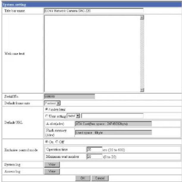
Title bar name
Type a name to display on the title bar up to 32 characters.
Welcome text
Type a text to show on the welcome page, in HTML format, up to 1,024 characters. Use the
tag for a line break. (A line break is equivalent to 2 characters.)
Serial No.
Displays the serial number of the camera.
Default frame rate
Select the initial frame rate which is selected when you log in the camera and display the main viewer page. Click the down-arrow button in the box and select the frame rate from the drop-down list.
The selectable frame rates are the following: SNC-Z20N:
1, 2, 3, 4, 5, 6, 8, 10, 15, 20, 25, Fastest SNC-Z20P:
1, 2, 3, 4, 5, 6, 8, 12, 16, 20, Fastest
The numbers indicate “FPS” (the number of frames transmitted per second).
With Fastest, the camera transmits the maximum number of frames possible for the connected line. The maximum frame rate is 30 FPS for the SNC-Z20N and 25 FPS for the SNC-Z20P.
Note
To update the main viewer page for the changed setting, click Refresh of the browser.
Default URL
Select the homepage to be displayed when you enter the IP address of the camera in the Address box of the browser.
To display the homepage built in the camera Select /index.html.
To display your individual homepage
You can display the favorite homepage that you have created using the CGI commands of the camera. Store the created HTML file in the recommended ATA memory card and insert the card into the PC card slot of the camera, or store the HTML file in the built-in flash memory using the Custom Homepage Installer included in the supplied CD-ROM.
1 Select User Setting.
2 Store the HTML file of the homepage you created into an ATA memory card and insert the card into the PC card slot of the camera. Or, store the HTML file in the built-in flash memory using the Custom Homepage Installer included in the supplied CD-ROM. For use of the Custom Homepage Installer, see page 49.
3 Select /adrv/ when using the ATA memory card, or /ddrv/ from the drop-down list when using the built-in flash memory.
4 Type the path of the homepage in the text box up to 64 characters.
For the verified cards, contact your authorized Sony dealer.
A-slot (adrv)
Displays the type of the PC card inserted into the PC card slot and its free card space.
Flash memory (ddrv)
Displays the file size stored in the built-in flash memory.
Exclusive control mode.
Limits the operation of the camera
If you select Off, multiple users can operate the camera at the same time. The operation by the user accessed later has priority.
If you select On, only one user can operate the camera. The period of operation allowed to one user is determined by the Operation time setting. If a user tries to operate the camera while another user is operating it, the control right is limited according to the Operation time and Maximum wait number settings.
Operation time
Sets the period that one user can operate the camera exclusively, between 10 and 600 sec.
This setting is valid when the Exclusive control mode menu is set to On.
Maximum wait number
Sets the maximum number of users that can wait to control the camera while another user is operating the camera. The selectable number is between 0 and 20. This setting is valid when the Exclusive control mode menu is set to On.
Notes
- Before using the Exclusive control mode, you need to set the date and time correctly on this camera and the connected computer.
- When you use the Exclusive control mode, enable the Cookie on your browser. The Exclusive control mode does not function if the Cookie is disabled.
- After you have changed a setting of the Exclusive control mode menu, click Refresh of the browser to update for the changed setting.
System log
Click View to display the Log file events page. The Log file events page shows the software version and troubleshooting information.
Access log
Click View to display the Access log page.
The Access log page shows the history of accessing the camera.
Date time setting Section
| Date time setting | ||
| Current date time | 2003-07-02 22:52:02 | |
| System(PC) current date time | 2003-07-04 15:53:29 | Apply |
| Manual current date time(26yy-mm-dd hh:mm:ss) | 20 03 - 01 - 01 00 - 00 00 | Apply |
| Time zone selecting | (GMT-05.00) Bogata, Lima, Quito, Eastern Time(US & Canada) | Apply |
| Date time format | yyyy mm-dd hh mm:ss | Apply |
| Synchronizationwith NTP server | On Off | |
| NTPserver name | ||
| Intervaltime 1 hours | Apply | |
Current date time
Displays the date and time set on the camera.
You can set the date and time using the following two methods.
Note
When you purchased the camera, be sure to check the date and time of the camera and set them if necessary.
System (PC) current date time
Displays the date and time set on your computer.
Click Apply to transfer the computer's date and time to the camera.
The set date and time are shown on Current date time.
Manual current date time
When you want to set the camera's date and time manually.
Select the lower 2-digits of the year, month, date, hour, minutes and seconds from each drop-down list. Click Apply to change the Current date time setting to the date and time you selected.
Time zone selecting
Set the time difference from Greenwich Mean Time in the area where the camera is installed. When you send an E-mail, the senting date and time is adjusted according to this setting.
Select the time zone where the camera is installed from the drop-down list. Click Apply to change the Current date time setting according to the selection.
Notes
- If the time zone selected on the Time zone selecting menu is different from that set on the computer, the time is adjusted using the time zone difference and set on the camera.
- Due to the network properties, there may be a slight difference between the actual time and the time set on the camera.
Date time format
Select the format of date and time to be displayed on the monitor image from the drop-down list.
You can select from among yyyy-mm-dd hh:mm:ss (year-month-day hour:minute:second), mm-dd-yyyy hh:mm:ss (month-day-year hour:minute:second), and dd-mm-yyyy hh:mm:ss (day-month-year hour:minute:second).
Click Apply to transfer the setting to the camera.
Synchronization with NTP server
Synchronizes the camera's time with that of the NTP (Network Time Protocol) server.
Select On to activate the time synchronization, and Off to deactivate it.
NTP server name
Type the host name or IP address of the NTP server, up to 64 characters.
This setting is valid when the Synchronization with NTP server menu is set to On.
Interval time
Select the interval at which you want to adjust the camera's time referring to the NTP server' time, between 1 and 24 hours. The set interval is a guide, and does not indicate the exact time.
This setting is valid when the Synchronization with NTP server menu is set to On.
Note
The time adjusted by this function may be slightly in error depending on the network environments between the camera and the NTP server.
Initialization Section
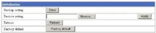
Backup setting
Saves the setting data of the camera in a file.
Click Save, and follow the instructions on the browser to specify the folder and save the setting data of the camera. The file name preset at the factory is "snc-z20.cfg."
Restore setting
Loads the stored setting data of the camera.
Click Browse and select the file in which the setting data is stored. Then, click Apply, and the camera is adjusted according to the loaded data and restarted.
Note
The IP address setting in the Wired LAN setting section (see page 21) on the Network setting page and the IP address setting in the Wireless LAN setting section (see page 22) cannot be set.
Reboot
Reboots the camera.
Click Reboot, and "The SNC-Z20 will be rebooted. Are you sure?" appears. Click OK to reboot the camera.
Factory default
Resets the camera to the factory settings.
Click Factory default, and "All configuration information will be initialized as factory setting. Are you sure?" appears. Click OK to reset to the factory settings.
Setting the Camera — Camera setting Page
When you click Camera on the Administrator menu, the Camera setting page appears.
Use this page to set the functions of the camera.
Note
To update the camera for the changed setting, click Apply on the changed item.
Camera setting Section
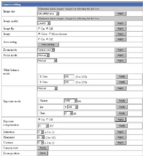
Image size
Select the size of the image to be transmitted to the computer.
You can select from among the following options. SNC-Z20N:
736 × 480 (Auto), 736 × 480 (Frame), 736 × 480 (Field), 640 × 480 (Auto), 640 × 480 (Frame), 640 × 480 (Field), 320 × 240, 160 × 120
SNC-Z20P:
736 × 544 (Auto), 736 × 544 (Frame), 736 × 544 (Field), 640 × 480 (Auto), 640 × 480 (Frame), 640 × 480 (Field), 320 × 240, 160 × 120
Frame is suitable for still images, and Field is suitable for animation.
If you select Auto, the image mode changes between Frame and Field automatically: Frame when the subject is a still object, and Field when the subject is moving.
Image quality
Select the image quality from Level 1 to Level 10. A higher level gives a higher image quality, but the frame rate decreases as the data size increases.
Tip
The following table shows the relation between the data size of a 24-bit image (8 bits for each R, G and B), and the compression rate for each Level setting. (in case of 640 × 480 image)
| Level Data size (approx.) Compression rate (approx.) |
| 1 15 KB 1/60 |
| 2 18 KB 1/50 |
| 3 22.5 KB 1/40 |
| 4 25.7 KB 1/35 |
| 5 30 KB 1/30 |
| 6 36 KB 1/25 |
| 7 45 KB 1/20 |
| 8 60 KB 1/15 |
| 9 90 KB 1/10 |
| 10 180 KB 1/5 |
Image Flip
You can display the image flipped vertically on the computer.
When you install the camera upside down, select On to view the image in correct way.
Note
When On is selected, the composite video signal output from the video output connector (BNC connector) on the rear of the camera is also flipped.
Image
Select Color or Monochrome.
Area setting
When the image size is 736 × 480 or 640 × 480 for the SNC-Z20N, or 736 × 544 or 640 × 480 for the SNC-Z20P, you can trim a portion of the image and display the trimmed image on the computer. With the trimming, the transmitting data size, and thus, the network load is reduced and a higher frame rate is obtained.
Select On for trimming the image, or Off for no trimming.
Click Area setting to display the Area setting page.
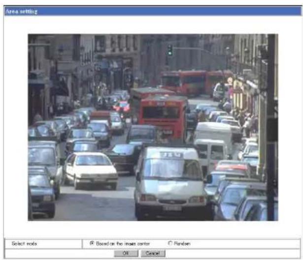
Select mode
Select the image trimming mode.
Base on the image center: The image is trimmed using the center of the image as the reference point. This setting is recommended when you perform zooming.
Random: The image is trimmed as you specify. This setting is recommended when you fix zooming.
To trim an image
1 Set the Image size menu to 736 × 480 or 640 × 480 for the SNC-Z20N, or 736 × 544 or 640 × 480 for the SNC-Z20P.
2 Set the Area setting menu to On, and click Apply.
3 Click the Area setting button. A still image is displayed.
4 Select the image trimming mode with the Select mode menu, and specify the trimming portion.
When Based on the image center is selected:
Click on the still image. The red frame that appears when you clicked indicates the trimming portion.
The trimming portion is determined as shown below:
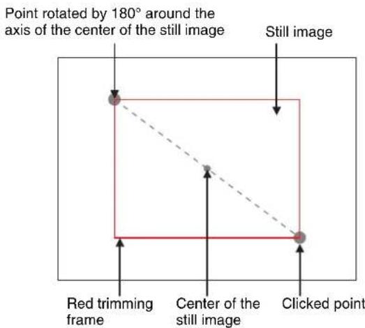
To change the trimming portion, click on another point on the image.
When Random is selected:
Click the left button of the mouse on the still image and drag it diagonally. The red frame that appears as you drag indicates the trimming portion.
5 Click OK at the bottom of the window.
The trimmed image is displayed on the main viewer page.
6 To close the image, click x on the upper-right corner.
Zoom mode
Select the zoom mode.
Select Full to operate the optical zoom of × 18 and the electronic zoom of × 12, giving × 216 in total. The electronic zoom will operate after the optical zoom.
Select Optical only to operate the optical zoom of × 18 only. In this case, you can use an electronic zoom of × 2 by clicking the DZOOM × 2 button on the main viewer page. To cancel the electronic zoom, click the DZOOM × 1 button. (See “Zooming” on page 10.)
Focus mode
Select the focus mode.
Select Auto to adjust the focus automatically.
Select Manual to adjust the focus manually using the NEAR and FAR buttons on the main viewer page. If you click the ONE PUSH AF button, the focus is adjusted instantly. (See "Focusing" on page 10.)
White balance mode
Select the white balance mode.
You can select from among Auto, Indoor, Outdoor,
One push WB, ATW and Manual.
If you select One push WB, the ONE PUSH
TRIGGER button is displayed. Click the button to adjust the white balance instantly.
If you select Manual, the R Gain and B Gain controls are displayed. Set 0 to 255 for each control.
Exposure mode
Select the exposure from among Full auto, Shutter priority, Iris priority and Manual.
The setting items required for each setting appear.
Full auto: Adjusts the exposure automatically using the electronic shutter, iris and gain. Select the Back light compensation menu On or Off.
Shutter priority: Adjusts the exposure automatically using the iris and gain. Select the electronic shutter speed from the Shutter drop-down list.
Iris priority: Adjusts the exposure automatically using the electronic shutter and gain. For the iris adjustment, select the F number from the Iris drop-down list.
Manual: Select the electronic shutter, iris and gain from the drop-down list for each control.
Back light compensation
Select On to activate the backlight compensation, or Off to deactivate it.
Shutter
Select the electronic shutter speed from among the following:
SNC-Z20N:
1/10000, 1/6000, 1/4000, 1/3000, 1/2000, 1/1500, 1/1000, 1/725, 1/500, 1/350, 1/250, 1/180, 1/125, 1/100, 1/90, 1/60, 1/30, 1/15, 1/8, 1/4, 1/2, 1 (seconds). SNC-Z20P:
1/10000, 1/6000, 1/3500, 1/3000, 1/2500, 1/1750, 1/1250, 1/1000, 1/600, 1/420, 1/300, 1/215, 1/150, 1/120, 1/100, 1/75, 1/50, 1/25, 1/12, 1/6, 1/3, 1/2, 1 (seconds).
Iris
Select the iris (F number) from among the following: F1.4, F1.6, F2, F2.4, F2.8, F3.4, F4.0, F4.8, F5.6, F5.8, F8.0, F9.6, F11, F14, F16, F19, F22, Close.
Gain
Select the gain (dB) from among the following: -3 dB, 0 dB, 2 dB, 4 dB, 6 dB, 8 dB, 10 dB, 12 dB, 14 dB, 16 dB, 18 dB, 20 dB, 22 dB, 24 dB, 26 dB, 28 dB
Note
When the shutter speed is set to 1 sec or 1/2 sec in the Shutter priority or Manual mode, set the Focus mode menu and the White balance mode menu to Manual.
Exposure compensation
When the Exposure mode menu is set to Full auto, Shutter priority or Iris priority, select On to activate the exposure compensation, or Off to deactivate it. When it is set to On, select the EV value from among the following: +1.75, +1.5, +1.25, +1, +0.75, +0.5, +0.25, 0, -0.25, -0.5, -0.75, -1, -1.25, -1.5, -1.75 (EV)
Saturation
Select the saturation in 7 steps, from -3 to 3. Selecting 3 gives the image with the highest saturation.
Note
The Saturation setting is effective for the computer image only. (It is not effective for the video signal output.)
Sharpness
Select the sharpness in 16 steps, from 1 to 16. Selecting 16 gives the image with the highest sharpness.
Contrast
Select the contrast in 7 steps, from -3 to 3. Selecting 3 gives the image with the highest contrast.
Note
The Contrast setting is effective for the computer image only. (It is not effective for the video signal output.)
Camera reset
Click Apply, and "Camera reset OK?" appears. Click OK on the dialog to reset the camera settings on the Camera setting page to the factory settings.
Zoom Position
Click Store to store the current zooming position in the memory of the camera. When the power is turned on next time, the stored zooming position is recalled.
Day/Night setting Section
| Day/Night setting | |
| Day/Night mode | ○ Disable ○ Auto ○ Manual ○ Timer |
| Day/Night | ○ On ○ Off |
| OK Cancel | |
Day/Night mode
Select the Day/Night mode that selects the IR (infrared) cut filter operation mode from among Disable, Auto, Manual and Timer.
After selecting the mode, click OK to update the camera to the selected mode.
Disable: The Day mode is always set.
Auto: The Day/Night mode is set automatically. It is normally set in the Day mode and changes to the Night mode in a dark place.
Note
The Day/Night mode is not switched to Night mode automatically when Exposure mode is set to Shutter priority, Iris priority or Manual in the Camera setting Section.
Manual: Set the Day/Night mode manually. If you select Manual, the Day/Night On/Off menu appears. Select On to set to the Night mode, and Off to the Day mode. You can also select the Day/Night mode from the trigger control parts (see page 11).
Timer: Set the Day/Night mode using the timer. If you select Timer, the Schedule No. menu appears at the bottom. Select the schedule so that the Day/Night mode is normally set to the Day mode, and it enters the Night mode at the start time of the schedule and returns to the Day mode at the end time.
Tip
If the Focus mode menu is set to Manual, the ONE PUSH AF function automatically operates when the Day mode and the Night mode are switched.
Schedule No.
When the Day/Night mode menu is set to Timer, click the check box of the desired schedule No.1 to 6 to activate the Day/Night mode.
To check the contents of the schedule, click Schedule check. (See "Setting the Schedule — Schedule setting Page" on page 40.)
OK/Cancel
See "Buttons common to every setting page" on page 14.
Camera control mode setting Section
You can set the operation mode for zooming using the TELE and WIDE buttons (see page 10), and for manual focusing using the NEAR and FAR buttons (see page 10).
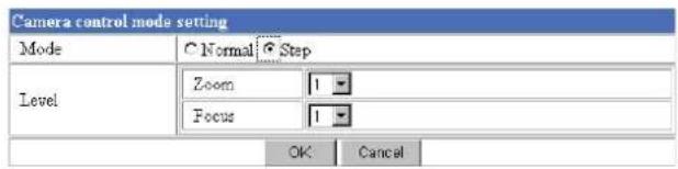
Mode
Select the operation mode of the mouse.
Normal: When you click the mouse button, the camera starts zooming operation, or the focus adjustment starts, and the operation/adjustment continues while you hold down the mouse button. To stop the operation/adjustment, release the mouse button.
Step: Each time you click the mouse button, the camera starts zooming or the focus adjustment operates by a transition level determined by Level. If you keep the mouse button held down for more than 1 second, the operation mode is temporarily changed to Normal. When you release the mouse button, the camera operation/adjustment stops and the Step mode is restored.
Level
Select the focus adjustment of the camera operation by clicking the mouse button once. This section is effective when Mode is set to Step.
Zoom: Select the camera transition level from 1 to 10 by clicking the TELE or WIDE button for zooming (see page 10). Selecting 10 gives the maximum transition level.
Focus: Select the focus adjustment transition level from 1 to 10 by clicking the FAR or NEAR button for manual focusing (see page 10). Selecting 10 gives the maximum transition level.
Note
When you have changed the Mode or Level setting, click the Control button on the menu section to update the setting on the image control section.
Configuring the Network — Network setting Page
When you click Network on the Administrator menu, the Network setting page appears.
Use this page to configure the network to connect the camera and the computer.
Wired LAN setting Section
This section provides the menus for connecting the camera through the Ethernet.
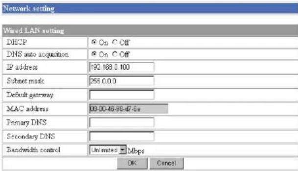
DHCP
Select On to assign the IP address to the camera automatically. When you have assigned a proper IP address to the camera, select Off.
Note
When you set DHCP to On, make sure that there is an DHCP server on the network.
DNS auto acquisition
When DHCP is set to On, select if the IP address of the DNS server is assigned automatically or not. Select On to assign the IP address of the DNS server automatically.
IP address
Type the IP address of the camera.
Subnet mask
Type the subnet mask.
Default gateway
Type the default gateway.
MAC address
Displays the MAC address of the camera.
Primary DNS
Type the IP address of the primary DNS server.
Secondary DNS
Type the IP address of the secondary DNS server, if necessary.
Bandwidth control
Limits the data communication bandwidth of the camera.
You can select from among the following:
Unlimited, 0.5, 0.6, 0.7, 0.8, 0.9, 1.0, 2.0, 3.0, 4.0, 5.0, 6.0, 7.0, 8.0 (Mbps)
Select Unlimited when you do not want to limit the bandwidth.
Notes
- If you limit the bandwidth, the camera performance may be affected, for example, the frame rate of image display may be reduced.
- The actual bandwidth may differ from the selected option depending on the network environments.
OK/Cancel
See “Buttons common to every setting page” on page 14.
Wireless LAN setting Section
This section provides the menus for connecting the camera through a wireless network, with the specified wireless LAN card inserted into the PC card slot of the camera.
Read the Operation Manual and Installation Guide of the wireless LAN card together with this guide.
Note
If you use the wireless function of this unit, set a network address defined by the IP address, subnet mask and default gateway in the Wireless LAN setting Section. In this case, the network address should be different from the priority connection set in the Wired LAN setting Section.
Verified wireless LAN adapter card
Cisco Aironet 350 Series Client Adapter: AIR-PCM352
For details on the wireless LAN card, consult your authorized Sony dealer or the store where you purchased the product.
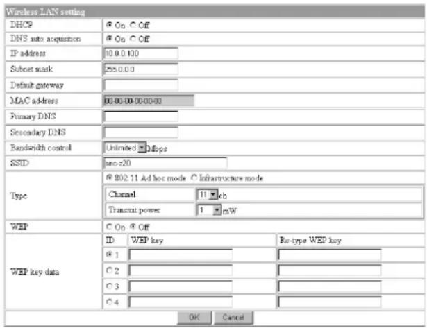
DHCP
Select On to assign the IP address to the camera automatically. When you have assigned a proper IP address to the camera, select Off.
Note
When you set DHCP to On, make sure that there is an DHCP server on the network.
DNS auto acquisition
When DHCP is set to On, select if the IP address of the DNS server is assigned automatically or not. Select On to assign the IP address of the DNS server automatically.
IP address
Type the IP address of the camera.
Subnet mask
Type the subnet mask.
Default gateway
Type the default gateway.
MAC address
Displays the MAC address of the wireless LAN card inserted into the PC card slot of the camera. If no card is inserted, 00-00-00-00-00-00 is displayed.
Primary DNS
Type the IP address of the primary DNS server.
Secondary DNS
Type the IP address of the secondary DNS server, if necessary.
Bandwidth control
Limits the data communication bandwidth for the wireless interface of the camera.
You can select from among the following:
Unlimited, 0.5, 0.6, 0.7, 0.8, 0.9, 1.0, 2.0, 3.0 (Mbps)
Select Unlimited when you do not want to limit the bandwidth.
SSID
Type the ID to identify the wireless network you want to access using up to 32 ASCII characters (upper and lower cases).
For your security, be sure to change the factory setting.
Type
Select the network connection type 802.11 Ad hoc mode or Infrastructure mode. When you select 802.11
Ad hoc mode, specify the wireless channel and the maximum transmission power.
Note
Specify the channel and transmission power conforming to the regulations of your country or region. For details, refer to the Operation Manual and Installation Guide of the wireless LAN card.
WEP
Select On when you use the WEP (Wired Equivalent Privacy) keys, or Off when you do not use it.
The WEP key data settings are valid only when the WEP menu is set to On.
WEP key data
Specify up to 4 WEP keys. The length of a WEP key is 40 or 104 bit. A 104-bit WEP key has a higher security level than a 40-bit key. You can type the WEP key either in hexadecimal numbers (0 to 9 and A to F) or ASCII characters.
When the Type menu is set to Infrastructure mode, the WEP key should be the same as that of the access point. When the Type menu is set to 802.11 Ad hoc mode, the WEP key should be the same as that of the communication client.
Notes
- Before removing the wireless LAN card from the camera, turn off the power of the camera.
- If a setting either in the Wired LAN setting section or the Wireless LAN setting section has changed, both the Ethernet and wireless interfaces are disconnected and initialized.
- The throughput of the data transmission/reception via the Ethernet may decrease when the wireless LAN card is in use.
HTTP port setting Section
You can set the port number for the HTTP server on the camera.

HTTP port No.
Normally select 80. If you want to use a port number other than 80, select the text box and type a port number between 1024 and 65535.
Note
When you have set the HTTP port No. to a number other than 80 on the Network setting page or in the Setup Program, access the camera by typing the IP address of the camera again on the web browser, as follows:
Example: when HTTP port No. is set to 8000

Notifying the IP Address — Dynamic IP address notification Section
When the DHCP menu is set to On, you can send the notification of the completion of the network settings (Wired LAN settings and Wireless LAN settings) using the SMTP or HTTP protocol.
| Dynamic IP address notification | ||
| SMTP | On Off | |
| SMTP server name | smtp.yoursmtpserver.com | |
| Recipient e-mail address | your_mail@youmail.com | |
| From e- mail address | your_mail@youmail.com | |
| Subject | Dynamic IP address notification | |
| Message | The URL is http://: The MAC address is . The model name is . The serial number is . | |
| HTTP | On Off | |
| URL | http:// | |
| Proxy server name | ||
| Proxy port No. | 8080 (1024 to 65535) | |
| Method | GET | |
| OK Cancel | ||
SMTP
Select On to send an E-mail when the DHCP setting is completed.
SMTP server name
Type the name or IP address of the SMTP server you want to use for sending an E-mail, up to 64 characters.
Recipient e-mail address
Type the recipient E-mail address up to 64 characters. You can specify only one recipient E-mail address.
From e-mail address
Type the E-mail address that is displayed in the From field of E-mails, up to 64 characters. This is used as the reply address or the address for the system mail from the mail server.
Subject
Type the subject/title of the E-mail up to 64 characters.
Message
Type the text of the E-mail up to 384 characters. You can describe the information of the acquired IP address, etc. using the special tags mentioned below.
HTTP
Select On to output a command to the HTTP server when the DHCP setting is completed. Using this function, you can configure a useful system, for example, to view the access log stored in the HTTP server or start an external CGI program.
URL
Specify the URL to send HTTP commands, up to 256 characters. The URL is normally described as follows:
http://ip_address[:port]/path?parameter
ip_address: Type the IP address or host name of the host to which you want to connect.
[:port]: Specify the port number to which you want to connect. If you want to use Well-known port number 80, you do not need to input this value.
path: Type the command name.
parameter: Type the command parameter if necessary. You can use the special tags mentioned below for the parameters.
Proxy server name
When you send HTTP commands via a proxy server, type the name or IP address of the proxy server, up to 64 characters.
Proxy port No.
Specify the port number when you send HTTP commands via the proxy server. Set the port number between 1024 and 65535.
Method
Select the HTTP method GET or POST.
About the special tags
You can use the following five special tags to allow the notification of the settings acquired by the DHCP, such as an IP address. Type the tags in the parameter section of the URL that you describe in the Message field of the SMTP menu.
Use this tag to embed the IP address acquired by the DHCP in the text or parameter.
Use this tag to embed the specified HTTP server port number in the text or parameters.
Use this tag to embed the MAC address of the interface which IP address you have acquired by the DHCP, in the text or parameter.
Use this tag to embed the camera's model name (SNC-Z20N or SNC-Z20P) in the text or parameter.
Use this tag to embed the camera's serial number in the text or parameter.
Setting the User — User setting Page
When you click User on the Administrator menu, the User setting page appears.
Use this page to set the user names and passwords of Administrator and up to 9 kinds of users (User 1 to User 9), and the access right of each user.
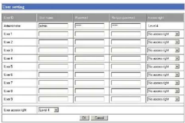
Administrator, User 1 to 9
Specify User name, Password, Re-type password and Access right for each user ID.
User name
Type a user name between 4 and 16 characters.
Password
Type a password between 4 and 16 characters.
Re-type password
To confirm the password, type the same characters as you typed in the Password box.
Note
If you type an incorrect character in the User name, Password or Re-type password box, a message like the following appears. In this case, click OK to cancel the message and re-type the correct character.
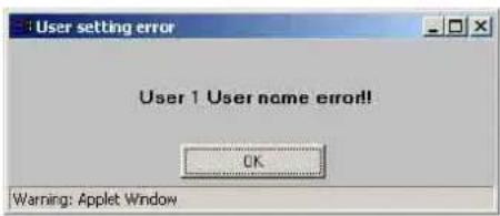
Access right
Select the access right for each user from the drop-down list. You can select from Level 1 to Level 4. The rights afforded to each access right are as follows:
Level 1: Allows monitoring of the camera image (including some operations for monitoring).
Level 2: Allows monitoring of the camera image and camera operations.
Level 3: Allows monitoring of the camera image, camera operations and manual application operations.
Level 4: Allows all the access right as Administrator.
No access right: Use this option when you want to prohibit access to the camera temporarily.
User access right
Select the level of the access right to require user authentication.
The authentication dialog will appear where user authentication is required.
Level 1: Performs user authentication when a user accesses the following pages: main viewer page (page 8), Camera control parts (page 10), Trigger control parts (page 11) or Administrator menu page (page 13).
Level 2: Performs user authentication when a user accesses the following pages: Camera control parts, Trigger control parts or Administrator menu page. No user authentication is required to display the main viewer page.
Level 3: Performs user authentication when a user accesses the following pages: Trigger control parts or Administrator menu page.
No user authentication is required to display the main viewer page or the Camera control parts.
Level 4: Performs user authentication when a user accesses the Administrator menu page only.
No user authentication is required to display the other pages.
OK/Cancel
See "Buttons common to every setting page" on page 14.
Setting the Security — Security setting Page
When you click Security on the Administrator menu, the Security setting page appears.
Use this page to limit the computers that can access the camera.
Activating/Deactivating the Security Function — Security usage setting Page

To activate the security function, select Use security function, then click OK. The Security setting page appears.
If you do not use the security function, select Do not use security function, then click OK.
Setting the Security Function —Securing setting Page
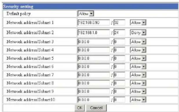
Default policy
Select the basic policy of the limit from Allow and Deny.
If you select Allow, you will basically allow access to the camera and only deny access from the computers specified on the Network address/Subnet 1 to Network address/Subnet 10 menus below.
If you select Deny, you will basically deny access to the camera, and only allow access from the computers specified on the Network address/Subnet 1 to Network address/Subnet 10 menus.
Network address/Subnet 1 to Network address/Subnet 10
Type the IP addresses and subnet mask values you want to allow or deny access to the camera.
You can specify up to 10 IP addresses and subnet mask values. For a subnet mask, type 8 to 32.
To temporarily cancel the Default Policy for a specified IP address/subnet mask, select Allow or Deny from the drop-down list on the right.
Tip
The subnet mask value represents the bit number from the left of the network address.
For example, the subnet mask value for 255.255.255.0 is 24.
If you set "192.168.0.0/24, Allow," you can allow access from the computers having an IP address between 192.168.0.0 and 192.168.0.255.
Note
You can access the camera even from a computer having the IP address whose access right is set to Deny, if you enter the user name and password set for Level 4 access right on the authentication dialog displayed.
OK/Cancel
See "Buttons common to every setting page" on page 14.
Sending Images to FTP Server
— FTP client setting Page
When you click FTP client on the Administrator menu, the FTP client setting page appears.
Use this page to set up for capturing and sending still images to an FTP server. You can capture a still image at the moment when a trigger occurs by an external sensor input, the built-in activity detection function or a manual trigger button, or capture sequenced still images before and after the trigger. The captured still image(s) is sent to the FTP server (FTP client function). You can also send still images periodically.
Activating/Deactivating the FTP Client Function
— FTP client usage setting Page

To activate the FTP client function, select Use FTP client function and click OK. The FTP client setting page appears.
When you do not use the FTP client function, select Do not use FTP client function and click OK.
Note
The frame rate and operability on the main viewer page may decrease while a file is being transmitted by the FTP client function.
Setting the FTP Client Function — FTP client setting Page
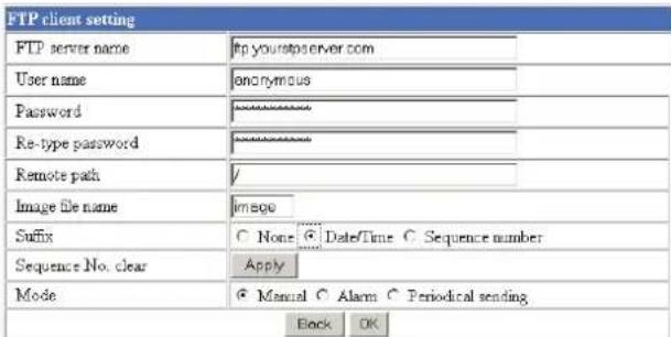
FTP server name
Type the FTP server name to upload still images up to 64 characters, or the IP address of the FTP server.
User name
Type the user name for the FTP server.
Password
Type the password for the FTP server.
Re-type password
To confirm the password, type the same characters as you typed in the Password box.
Remote path
Type the path to the destination up to 64 characters.
Image file name
Type the basic file name you want to assign to the images when sending to the FTP server. You can use up to 6 alphanumeric, - (hyphen) and _ (underscore) for naming.
Suffix
Select the suffix to add to the file name.
None: No suffix is added. The basic file name is assigned to the image to be sent to the FTP server.
Date/Time: The date/time suffix is added to the file name.
The date/time suffix consists of lower two-digits of year (2 digits), month (2 digits), date (2 digits), hour (2 digits), minute (2 digits), second (2 digits) and consecutive number (2 digits), thus 14-digit number is added to the file name.
Sequence number: A consecutive number is added to the basic file name. A number of up to 10 digits between 0000000000 and 4294967295 is added to the file name.
Tip
When the Mode menu is set to Alarm, the type of alarm and the capture timing to the alarm are added to the suffix.
Type of alarm: S1 (Sensor), AD (Activity Detection) Capture timing: PR (Pre-alarm), JT (Just alarm), PT (Post-alarm)
Sequence No. clear
Click Apply to reset the Sequence number suffix to 0.
Mode
Select the mode of the FTP client function.
Manual: Sends still images to the FTP server manually. After selecting Manual, click OK. The FTP client function mode is set to Manual.
In this mode, when you click the Trigger) button on the main viewer page, a still image is captured and sent to the FTP server. (See "Controlling the Application Manually" on page 11.)
Alarm: Sends still images to the FTP server by synchronizing with an external sensor input or the built-in activity detection function. When you select Alarm, the Alarm mode setting section appears (see page 28).
Note
If the Suffix menu is set to None, you cannot select the Alarm mode. When you want to use the Alarm mode, set the Suffix menu to Date/Time or Sequence number.
Periodical sending: Sends still images to the FTP server periodically. When you select Periodical sending, the Periodical sending mode setting section appears (see page 29).
Back/OK
See “Buttons common to every setting page” on page 14.
Alarm mode setting Section
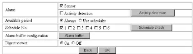
Alarm
Select the alarm to link the FTP client function. If the selected alarm is detected, the still images before and after the alarm are captured sequentially and sent to the FTP server.
Sensor: External sensor connected to sensor input of the camera I/O port
Activity detection: The activity detection function built in the camera
To set the activity detection function, click Activity detection. The Activity detection setting page appears (see page 41).
Available period
Select the period for which the selected alarm mode is available.
Always: The selected alarm mode is available any time.
Use scheduler: The selected alarm mode is available according to the schedule selected in Schedule No. below.
Schedule No.
When Use scheduler is selected on the Available period menu, select the schedule you want the selected alarm mode being available.
Click to select the check box(es) 1 to 6. You can select multiple schedules.
To check the contents of schedules, click Schedule check. (See “Setting the Schedule — Schedule setting Page” on page 40.)
Alarm buffer configuration
Click Alarm buffer to display the Alarm buffer setting page.
For details, see “Setting the Alarm Buffer — Alarm buffer setting Page” on page 39.
Note
If an alarm occurs during the Alarm buffer processing, that alarm is ignored.
Digest viewer
If you select On, an HTML file (.html) and a Java Script file (.js) are added each time the selected alarm is detected.
When you open the added HTML file using a general browser, the digest viewer runs and you can view the still pictures in the alarm buffer in sequence (quasi-animation).
See “Operating the Digest Viewer” on page 30.
Periodical sending mode setting Section
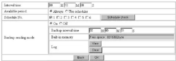
Interval time
Type the interval at which you want to send images to the FTP server periodically. You can set the hour (H), minutes (M) and seconds (S) between 1 second and 24 hours (one day).
Note
The actual interval may be longer than the set value, depending on the image size and the network environments.
Available period
Select the period for which the periodical sending mode is available.
Always: The periodical sending mode is available any time.
Use scheduler: The periodical sending mode is available according to the schedule selected in Schedule No. below.
Schedule No.
When Use scheduler is selected on the Available period menu, select the schedule you want the periodical sending mode being available.
Click to select the check box(es) 1 to 6. You can select multiple schedules.
To check the contents of schedules, click Schedule check. (See “Setting the Schedule — Schedule setting Page” on page 40.)
Backup sending mode
You can temporarily store (back up) still image data in the built-in memory (about 8 MB) when uploading to the FTP server is impossible due to a network failure, etc.
When the network recovers, the backup image data is uploaded to the FTP server.
This function is available only when Periodical sending is selected.
Select On to enable the Backup function.
Notes
- The Backup sending mode cannot be set to On when the image memory function (page 38) is activated. When you want to use the Backup function, deactivate the image memory function.
- When the backup memory capacity is full or the backup images exceed 2,560, new image data will not be stored. (The previously stored images are retained.)
- Backup image data is erased when the power of the camera is turned off.
Backup interval time
Specify the interval at which you want to send the backup image data to the FTP server. You can set a value between 1 second and the time set on the Interval time menu.
Note
The actual interval may be longer than the set value depending on image size and the network environments.
Built-in memory
Displays the built-in memory space.
Log
Click View to display the Backup FTP log page to show network failures and event information.
Click Clear to delete the log contents.
Note
The log contents are cleared when the power of the camera is turned off.
Operating the Digest Viewer
If you download the HTML file, the Java Script file and the JPEG image files to your computer and open HTML file using a general browser, the digest viewer is displayed on the screen.
Digest viewer
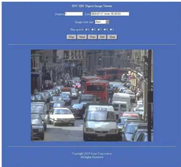
Number
Displays the consecutive still image number.
Date
Displays the date and time when the image is captured.
Image view size
Select the image size to be displayed on the digest viewer from among the following: Auto, 160 × 120, 320 × 240, 640 × 480
When you select Auto, the image is displayed in the size specified with the Image size menu on the Camera setting page (see page 17).
Play speed
Select the play speed from 1 to 5. 5 is the highest speed.
Note
Whether you can play the image at a high speed depends on the performance of your computer. You may need to select a lower speed.
Play
Click this button to start playing. Playing stops when the last still image is displayed.
Next
When a still image is displayed, click this button to display the next numbered still image.
Prev (previous)
When a still image is displayed, click this button to display the previous numbered still image.
Still
Click this button to stop playing temporarily.
Stop
Click to stop playing. The still image of number 1 is displayed.
Downloading Images from the Camera — FTP server setting Page
When you click FTP server on the Administrator menu, the FTP server setting page appears. Use this page to set up for the FTP server function which finds a specified still image file stored in the built-in memory of the camera (about 8 MB) or the ATA memory card inserted into the PC card slot, or download the still image file from the card.
Activating/Deactivating the FTP Server Function — FTP server usage setting Page

To activate the FTP server function, select Use FTP server function and click OK. The FTP server setting page appears. When you do not use the FTP server function, select Do not use FTP server function and click OK.
Notes
- The frame rate and operability on the main viewer page may decrease when the FTP server function is used.
- Deactivate the FTP server function before removing the ATA memory card or turning off the power of the camera with the ATA memory card inserted.
Setting the FTP Server Function — FTP server setting Page
You can register up to 10 user names and passwords to allow logging in the camera using the FTP client software of the computer.
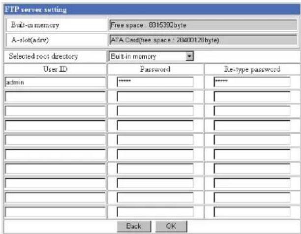
Built-in memory
Displays the free space of the built-in memory of the camera.
A-slot (adrv)
Displays the type of the PC card inserted into the PC card slot and its free card space.
Selected root directory
Select from the drop-down list, the directory under which the image file you want to find or download is stored.
Built-in memory: Built-in memory of the camera ATA memory card: ATA memory card inserted into PC card slot of the camera
User ID
Type a user name between 4 and 16 characters.
Password
Type a password between 4 and 16 characters.
Re-type password
To confirm the password, type the same characters as you typed in the Password box.
Back/OK
See "Buttons common to every setting page" on page 14.
Sending an Image via E-mail — SMTP setting Page
When you click SMTP on the Administrator menu, the SMTP setting page appears.
Use this page to set up for the SMTP function that can capture and send a still image attached to an E-mail. You can capture a still image at the moment when a trigger occurs by an external sensor input, the built-in activity detection function or a manual trigger button. The captured still image is sent as an attachment of the E-mail. You can also send a still image periodically.
Activating/Deactivating the SMTP Function — SMTP usage setting Page
| SMTP usage setting | |
| ○ Use SMTP function | |
| ◎ Do not use SMTP function | |
| OK Cancel | |
To activate the SMTP function, select Use SMTP function and click OK. The SMTP setting page appears.
When you do not use the SMTP function, select Do not use SMTP function and click OK.
Notes
The frame rate and operability on the main viewer page may decrease while an image file is being transmitted via an E-mail.
Setting the SMTP Function — SMTP setting Page
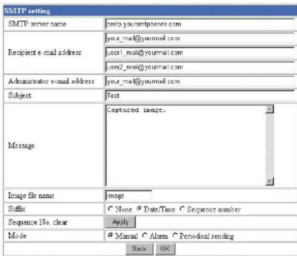
SMTP server name
Type the SMTP server name up to 64 characters, or the IP address of the SMTP server.
Recipient e-mail address
Type the recipient E-mail address up to 64 characters. You can specify up to three recipient E-mail addresses.
Administrator e-mail address
Type the Administrator e-mail address up to 64 characters.
This address is used for reply mail and sending error messages from the camera.
Subject
Type the subject/title of the E-mail up to 64 characters.
Message
Type the text of the E-mail up to 384 characters. (A line break is equivalent to 2 characters.)
Image file name
Type the basic file name you want to assign to the image to attach an E-mail. You can use up to 6 alphanumeric, - (hyphen) and _ (underscore) for naming.
Suffix
Select the suffix to add to the file name.
None: No suffix is added. The basic file name is assigned to the image to be sent via an E-mail.
Date/Time: The date/time suffix is added to the file name.
The date/time suffix consists of lower two-digits of year (2 digits), month (2 digits), date (2 digits), hour (2 digits), minute (2 digits) and second (2 digits), thus 12-digit number is added to the file name.
Sequence number: A consecutive number is added to the basic file name. A number of up to 10 digits between 0000000000 and 4294967295 is added to the file name.
Sequence No. clear
Click Apply to reset the Sequence number suffix to 0.
Mode
Select the mode of the SMTP function.
Manual: Sends a still image attached to an E-mail manually. After selecting Manual, click OK. The SMTP function mode is set to Manual. In this mode, when you click the (Trigger) button on the main viewer page, a still image is captured and sent via an E-mail. (See “Controlling the Application Manually” on page 11.)
Alarm: Sends a still image via an E-mail by synchronizing with an external sensor input or the built-in activity detection function. When you select Alarm, the Alarm mode setting section appears (see page 33).
Periodical sending: Sends a still image via an E-mail periodically. When you select Periodical sending, the Periodical sending mode setting section appears (see page 33).
Back/OK
See “Buttons common to every setting page” on page 14.
Alarm mode setting Section
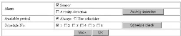
Alarm
Select the alarm to link the SMTP function. If the selected alarm is detected, a still image is captured and sent via an E-mail.
Sensor: External sensor connected to sensor input of the camera I/O port
Activity detection: The activity detection function built in the camera.
To set the activity detection function, click Activity detection. The Activity detection setting page appears (see page 41).
Note
The image that can be attached to an E-mail is the one captured at the moment when an alarm is input. If the next alarm occurs while the captured image is being processed, that alarm is ignored.
Available period
Select the period for which the alarm mode is available.
Always: The alarm mode is available any time.
Use scheduler: The alarm mode is available according to the schedule selected on the Schedule No. menu below.
Schedule No.
When Use scheduler is selected on the Available period menu, select the schedule you want the alarm mode being available.
Click to select the check box(es) 1 to 6. You can select multiple schedules.
To check the contents of schedules, click Schedule check. (See “Setting the Schedule — Schedule setting Page” on page 40.)
Periodical sending mode setting Section

Interval time
Type the interval at which you want to send an E-mail with a still image periodically. You can set the hour (H) and minutes (M) between 30 minutes and 24 hours (one day).
Available period
Select the period for which the periodical sending mode is available.
Always: The periodical sending mode is available any time.
Use scheduler: The periodical sending mode is available according to the schedule selected on the Schedule No. menu below.
Schedule No.
When Use scheduler is selected on the Available period menu, select the schedule you want the periodical sending mode being available.
Click to select the check box(es) 1 to 6. You can select multiple schedules.
To check the contents of schedules, click Schedule check. (See “Setting the Schedule — Schedule setting Page” on page 40.)
Setting the Alarm Out 1 or 2
— Alarm out 1 or 2 setting Page
When you click Alarm out 1 on the Administrator menu, the Alarm out 1 setting page appears. When you click Alarm out 2 on the Administrator menu, the Alarm out 2 setting page appears.
Use these pages to set up for the Alarm out function that controls the alarm out 1 or alarm out 2 of the I/O port located on the rear the camera. You can control the alarm out when a trigger occurs by an external sensor input, the built-in activity detection function, a manual trigger button, the Day/Night function or the timer.
The setting items for alarm out 1 and alarm out 2 are the same. This section explains how to set alarm out 1 as an example.
Activating/Deactivating the Alarm Out 1 Function
— Alarm out 1 usage setting Page

To activate the Alarm out 1 function, select Use alarm out 1 function and click OK. The Alarm out 1 setting page appears.
When you do not use the Alarm out 1 function, select Do not use alarm out 1 function and click OK.
Setting the Alarm Out 1 Function — Alarm out 1 setting Page

Mode
Select the mode of the Alarm out 1 function.
Manual: Controls the alarm out 1 manually. In this mode, you can short-circuit and open the alarm out 1 by clicking the Trigger) button on the main viewer page. (See “Controlling the Application Manually” on page 11.)
Day/Night: Controls alarm out 1 by synchronizing with the Day/Night function of the camera. When you select Day/Night, the Day/Night setting button appears. Click the button, and the Camera setting page appears and you can set the Day/Night function (see page 20).
In the Night mode, the relay corresponding to the alarm out 1 is short-circuited. In the Day mode, it is open.
Alarm: Controls alarm out 1 by synchronizing with an external sensor input or the built-in activity detection function. When you select Alarm, the Alarm mode setting section appears (see page 34).
Timer: Controls alarm out 1 by the timer. When you select Timer, the Timer mode setting section appears (see page 35).
Alarm mode setting Section
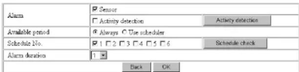
Alarm
Select the alarm to link the alarm out 1 function. If the selected alarm is detected, the alarm out 1 status changes.
Sensor: External sensor connected to sensor input of the camera I/O port
Activity detection: The activity detection function built in the camera.
To set the activity detection function, click Activity detection. The Activity detection setting page appears (see page 41).
Available period
Select the period for which the alarm mode is available.
Always: The alarm mode is available any time.
Use scheduler: The alarm mode is available according to the schedule selected on the Schedule No. menu below.
Schedule No.
When Use scheduler is selected on the Available period menu, select the schedule you want the alarm mode being available.
Click to select the check box(es) 1 to 6. You can select multiple schedules.
To check the contents of schedules, click Schedule check. (See “Setting the Schedule — Schedule setting Page” on page 40.)
Alarm duration
Select the duration for which the alarm output is short-circuited between 1 and 60 sec.
Timer mode setting Section

Schedule No.
Select the schedule you want to activate the alarm out 1 timer mode.
Click to select the check box(es) 1 to 6. You can select multiple schedules.
The alarm out 1 is short-circuited at the start time of the selected schedule, and it switches to open at the end time.
To check the contents of schedules, click Schedule check. (See “Setting the Schedule — Schedule setting Page” on page 40.)
Recording Images in Memory
— Image memory setting Page
When you click Image memory on the Administrator menu, the Image memory setting page appears. Use this page to set up for the image memory function which captures a still image and records it in the built-in memory of the camera (about 8 MB) or the ATA memory card. You can capture a still image at the moment when a trigger occurs by an external sensor input, the built-in activity detection function or a manual trigger button. The captured still image is recorded in the built-in memory or the ATA memory card. You can also record a still image periodically.
The recorded image file can be found or downloaded to the computer using the FTP server function. (See "Downloading Images from the Camera — FTP server setting Page" on page 31.)
For the verified cards, contact your authorized Sony dealer.
Activating/Deactivating the Image Memory Function — Image memory usage setting Page
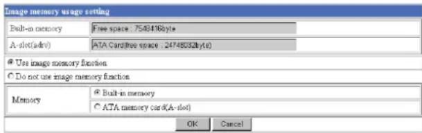
Built-in memory
Displays the free space of the built-in memory of the camera.
A-slot
Displays the type of the PC card inserted into the PC card slot and its free card space."
Use image memory function/Do not use image memory function
To activate the Image memory function, select Use image memory function and click OK. The Image memory setting page appears. When you do not use the Image memory function, select Do not use image memory function and click OK.
Memory
Select the memory you want to store the image to, from the drop-down list.
Built-in memory: Built-in memory of the camera (about 8 MB)
ATA memory card: ATA memory card inserted into PC card slot of the camera
Notes
- The image recorded in the built-in memory will be erased when the power of the camera is turned off.
- The frame rate and operability on the main viewer page may decrease during image storage.
- Deactivate the image memory function before removing the ATA memory card or turning off the power of the camera with the ATA memory card inserted.
- The image memory function cannot be activated if the Backup sending mode menu is set to On. To use the image memory function, set the Backup sending mode menu to Off.
- When you remove or insert a card, wait at least 10 seconds.
Recording an Image in the Selected Memory — Image memory setting Page
![Image memory setting[Built-in memory] Image file name Image Suffix None Date/Time Sequence number Sequence No. Clear Apply Overwrite On Off capacity warning On Off SMTP server name Administrator e-mail address Mode Manual Alarm Periodical recording Back OK](/content/2026/05/920516/images/9671a14dd6dc731cd593ee60b2113e89d9d2c55535945fc79cd6a01bafc5abc8.jpg)
Image file name
Type the basic file name you want to assign to the images when saving in the memory. You can use up to 6 alphanumeric, - (hyphen) and _ (underscore) for naming.
Suffix
Select the suffix to add to the file name.
None: No suffix is added. The basic file name is assigned to the image to be recorded in memory.
Date/Time: The date/time suffix is added to the file name.
The date/timer suffix consists of lower two-digits of
year (2 digits), month (2 digits), date (2 digits), hour (2 digits), minute (2 digits), second (2 digits) and consecutive number (2 digits), thus 14-digit number is added to the file name.
Sequence number: A consecutive number is added to the basic file name. A number of up to 10 digits between 0000000000 and 4294967295 is added to the file name.
Tip
When the Mode menu is set to Alarm, the type of alarm and the capture timing to the alarm are added to the suffix.
Type of alarm: S1 (Sensor), AD (Activity Detection) Capture timing: PR (Pre-alarm), JT (Just alarm), PT (Post-alarm)
Sequence No. clear
Click Apply to reset the Sequence number suffix to 0.
Overwrite
Select if you overwrite the file or not when there is insufficient memory space to record the image. Select On to allow overwriting. The oldest file or folder is overwritten first.
Select Off to prohibit overwriting. In this case, a new file cannot be stored.
Capacity warning
Select On to send a warning mail to the Administrator when the built-in memory space is low or the memory is full due to activation of the image memory function.
Select Off if you do not want to send a warning mail. If On is selected, the SMTP server name and Administrator e-mail address menus appear.
SMTP server name
Type the name or IP address of the SMTP server you want to use for sending the E-mail, up to 64 characters.
Administrator e-mail address
Type the E-mail address of the recipient of the warning mail (E-mail address of the Administrator), up to 64 characters.
Mode
Select the mode of the Image memory function.
Manual: Records a still image in the selected memory manually.
In this mode, when you click the (Trigger) button on the main viewer page, a still image is captured and recorded in the selected memory. (See "Controlling the Application Manually" on page 11.)
Alarm: Records a still image in the selected memory by synchronizing with an external sensor input or the built-in activity detection function. When you select Alarm, the Alarm mode setting section appears (see page 37).
Note
If the Suffix menu is set to None, you cannot select the Alarm mode. When you want to use the Alarm mode, set the Suffix menu to Date/Time or Sequence number.
Periodical recording: Records still images in the selected memory periodically. When you select Periodical recording, the Periodical recording mode setting section appears (see page 37).
Alarm mode setting Section
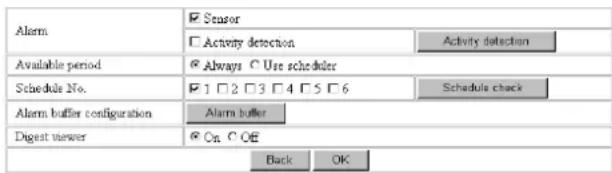
Alarm
Select the alarm to link the Image memory function. If the selected alarm is detected, a still image is captured and recorded in the selected memory.
Sensor: External sensor connected to sensor input of the camera I/O port
Activity detection: The activity detection function built in the camera.
To set the activity detection function, click Activity detection. The Activity detection setting page appears (see page 41).
Available period
Select the period for which the alarm mode is available.
Always: The alarm mode is available any time.
Use scheduler: The alarm mode is available according to the schedule selected in the Schedule No. menu below.
Schedule No.
When Use scheduler is selected on the Available period menu, select the schedule you want the alarm mode being available.
Click to select the check box(es) 1 to 6. You can select multiple schedules.
To check the contents of schedules, click Schedule check. (See “Setting the Schedule — Schedule setting Page” on page 40.)
Alarm buffer configuration
Click Alarm buffer to display the Alarm buffer setting page.
For details, see “Setting the Alarm Buffer — Alarm buffer setting Page” on page 39.
Note
If an alarm occurs during the Alarm buffer processing, that alarm is ignored.
Digest viewer
If you select On, an HTML file (.html) and a Java Script file (.js) are added each time the selected alarm is detected.
When you open the added HTML file using a general browser, the digest viewer runs and you can view the still pictures in the alarm buffer in sequence (quasi-animation).
See "Operating the Digest Viewer" on page 30.
Periodical recording mode setting Section
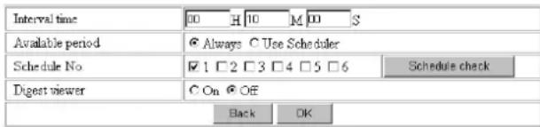
Interval time
Type the interval at which you want to record an image periodically. You can set the hour (H), minutes (M) and seconds (S) between 1 second and 24 hours (one day).
Note
The actual interval may be longer than the set value, depending on the image size and the recording conditions of the ATA memory card.
Available period
Select the period for which the periodical recording mode is available.
Always: The periodical recording mode is available any time.
Use scheduler: The periodical recording mode is available according to the schedule selected in the Schedule No. menu below.
Schedule No.
When Use scheduler is selected on the Available period menu, select the schedule you want the periodical recording mode being available.
Click to select the check box(es) 1 to 6. You can select multiple schedules.
To check the contents of schedules, click Schedule check. (See “Setting the Schedule — Schedule setting Page” on page 40.)
Digest viewer
If you select On, an HTML file (.html) and a Java Script file (.js) are added every 100 files.
When you open the added HTML file using a general browser, the digest viewer runs and you can view the still pictures in the alarm buffer in sequence (quasi-animation).
See "Operating the Digest Viewer" on page 30.
Note
If the Suffix menu is set to None, you cannot select On. When you want to use the digest viewer, set the Suffix menu to Date/Time or Sequence number.
Back/OK
See "Buttons common to every setting page" on page 14.
Directory Structure of Image Memory
The images are recorded in the memory with the following directory structure.
ATA memory card (A-slot): Slot A Built-in memory: Drive C
Slot A or drive C has the following directory structure.
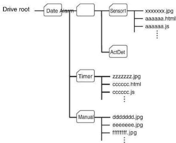
flowchart
graph TD
    A["Drive root"] --> B["Date Alarm"]
    B --> C["Sensor1"]
    C --> D["xxxxxxxx.jpg"]
    C --> E["aaaaaa.html"]
    C --> F["aaaaaa.js"]
    C --> G["..."]
    B --> H["ActDet"]
    H --> I["Timer"]
    I --> J["zzzzzzz.jpg"]
    I --> K["cccccc.html"]
    I --> L["cccccc.js"]
    I --> M["..."]
    B --> N["Manual"]
    N --> O["ddddddd.jpg"]
    N --> P["eeeeeee.jpg"]
    N --> Q["ffffff.jpg"]
    N --> R["..."]
A represents a folder created automatically. The Date folder has a 6-digit folder name consisting of the lower two digits of year (2 digits), month (2 digits) and date (2 digits). The Sensor, and Act Det (activity detection) folders correspond to alarm modes. The Timer folder corresponds to the periodical recording mode. And, the Manual folder corresponds to the manual mode.
JPEG image files are stored in each folder. If the digest viewer is allowed, an HTML file (.html) and a Java Script file (.js) are created automatically at the time of each alarm event. For the periodical recording mode, an HTML file (.html) and a Java Script file (.js) are created automatically every 100 JPEG image files.
Setting the Alarm Buffer — Alarm buffer setting Page
When you click Alarm buffer on the Administrator menu, the Alarm buffer Setting page appears. Use this page to set up for the alarm buffer used in the FTP client function (see page 27) and the Image memory function (see page 35).
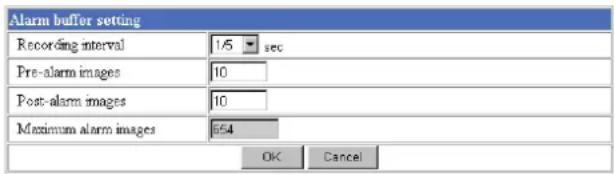
Recording interval
Select the interval (in seconds) at which you want to record an image in the alarm buffer.
You can select from among the following intervals: SNC-Z20N:
1/30, 1/15, 1/10, 1/5, 1/2, 1, 2, 3, 4, 5, 6, 7, 8, 9, 10 (seconds)
SNC-Z20P:
1/25, 1/12, 1/8, 1/5, 1/2, 1, 2, 3, 4, 5, 6, 7, 8, 9, 10 (seconds)
Pre-alarm images
Type the number of images to be recorded before detecting an alarm (Pre-alarm).
Post-alarm images
Type the number of images to be recorded after detecting an alarm (Post-alarm).
Maximum alarm images
Displays the maximum number of images that can be recorded in the alarm buffer with the current image size and image quality.
Note
The number of Maximum alarm images differs depending on the Image size and Image quality settings on the Camera setting page.
Check the Maximum alarm images setting and set so that the total number of Pre-alarm images and Post-alarm images does not exceed the Maximum alarm images.
If you set both Pre-alarm images and Post-alarm images to 0, only one image is recorded at the moment when an alarm is detected.
OK/Cancel
See “Buttons common to every setting page” on page 14.
Communicating Data via Serial Port
— Serial setting Page
When you click Serial on the Administrator menu, the Serial setting page appears.
Use this page to set up for the date communication via the serial interface. You can input data from a computer via the network to the camera, and output it to an external serial interface for controlling a peripheral device, or, vice versa, input data from a peripheral device to the camera via the external serial interface and output it to the computer via the network.
Perform the setting to match the peripheral device you connect to the camera.
The external serial interface of this camera conforms to RS232C standards.
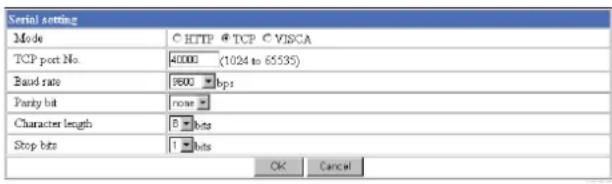
Mode
Select the port through which you send and receive data via the network: HTTP (HTTP Generic Driver) or TCP (TCP Generic Driver), or select if the camera is controlled using the VISCA protocol.
HTTP: When you select HTTP, you can realize data communication by creating an HTML program with CGI commands embedded in the computer. For the CGI commands, consult your authorized Sony dealer.
TCP: When you select TCP, specify the TCP port number on the TCP Port No. menu, and you can send and receive data that is input to or output from the external serial communication port. You can check the connection to the camera using a DOS command "telnet [host name] [assigned port number]".
VISCA: When you select VISCA, you can control the camera using the VISCA protocol.
For the command list of the VISCA protocol, consult your authorized Sony dealer.
Notes
- When you control the camera via the serial port using the VISCA protocol, match the communication settings with those on the connected controller.
- This camera does not support the daisy chain connection of VISCA devices. Connect the camera and the controller one for one.
TCP port No.
When you select TCP on the Mode menu, type the port number for the TCP port (TCP Generic Driver). Set a port number other than Well-Known port numbers (0 to 1023).
Baud rate
Select the communication baud rate for the peripheral device connected to the serial interface. You can select from among the following baud rates: 38400, 19200, 9600, 4800, 2400, 1200, 600, 300 (bps)
Parity bit
Select the parity bit for the peripheral device connected to the serial interface: None, Odd or Even.
Character length
Select the character length for the peripheral device connected to the serial interface: 7 or 8 (bits).
Stop bits
Select the stop bit for the peripheral device connected to the serial interface: 1 or 2 (bits).
OK/Cancel
See “Buttons common to every setting page” on page 14.
Setting the Schedule — Schedule setting Page
When you click Schedule on the Administrator menu, the Schedule setting page appears.
Use this page to set up to six schedules used for the Day/Night function, FTP client function, SMTP function, Alarm out 1 or 2 function and Image memory function.
| Schedule setting | |
| Schedule No. | Time table (00:00 to 24:00) |
| No.1 | Start time:00 H 00 M - End time:24 H 00 M Mon Tue Wed Thu Fri Sat Sun |
| No.2 | Start time:00 H 00 M - End time:24 H 00 M Mon Tue Wed Thu Fri Sat Sun |
| No.3 | Start time:00 H 00 M - End time:24 H 00 M Mon Tue Wed Thu Fri Sat Sun |
| No.4 | Start time:00 H 00 M - End time:24 H 00 M Mon Tue Wed Thu Fri Sat Sun |
| No.5 | Start time:00 H 00 M - End time:24 H 00 M Mon Tue Wed Thu Fri Sat Sun |
| No.6 | Start time:00 H 00 M - End time:24 H 00 M Mon Tue Wed Thu Fri Sat Sun |
| OK Cancel | |
Schedule No. 1 to Schedule No. 6
For each schedule, specify Start time (hour and minutes) and End time (hour and minutes), and check the days of the week that you want to activate the function.
OK/Cancel
See “Buttons common to every setting page” on page 14.
Setting the Activity Detection Function — Activity detection setting Page
When you click Activity detection on the Administrator menu, the Activity detection setting page appears. Use this page to set up for the activity detection to link various applications.
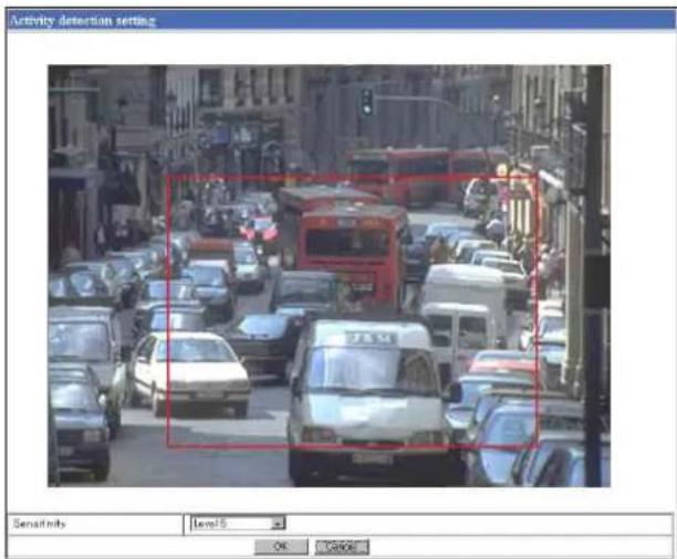
Sensitivity
Select the sensitivity of the activity detection from the drop-down list. You can select the sensitivity between Level 1 and Level 9. Level 9 is the maximum sensitivity.
Tip
The Sensitivity of the activity detection means a proportion of the changed area (pixels) to the whole activity detection area.
OK/Cancel
See "Buttons common to every setting page" on page 14.
Setting the Activity Detection Area
Set the activity detection working area as follows:
1 Determine the view angle of the camera at which you want to perform activity detection, using the zoom.
2 Click Activity detection on the Administrator menu.
A still picture is captured and the Activity detection setting page appears.
3 Hold down the mouse left button and drag it diagonally.
The portion marked with a red frame determines the activity detection working area.
As the default setting, the whole area is set as the activity detection working area.
Note
Before using the activity detection, perform the operation test to confirm correct operation.
The activity detection may not operate correctly in the following cases:
- when the Day/Night function is activated on the Camera setting page
– while changing a setting on the Camera setting page - when the Focus mode menu is set to Auto on the Camera setting page
- while zooming in
- when the object is dark
- when the camera is installed in an unstable place that causes vibration to the camera
Showing the Pop-up — Pop-up setting Page
When you click Pop-up on the Administrator menu, the Pop-up setting page appears.
Use this page to set up for displaying a pop-up with your favorite message on the computers monitoring the camera image, or for displaying a pop-up automatically when there is an alarm input.
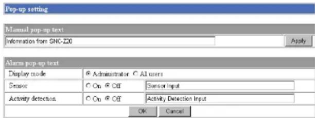
Manual pop-up text
Type the text to be displayed on a pop-up between 1 and 64 characters.
Click Apply to display the pop-up on all the computers monitoring the camera.
Alarm pop-up text
Display mode
Select the computer on which you want to display a pop-up when an alarm is input.
Administrator: The pop-up is displayed only on the computer monitoring the camera image as the Administrator.
All users: The pop-up is displayed on all the computers monitoring the camera image.
Sensor/Activity detection
Select On to show a pop-up when an alarm occurs by the earch corresponding sensor. Select Off not to show it. On each text box, type the text to be displayed on the pop-up between 1 and 64 characters.
OK/Cancel
See “Buttons common to every setting page” on page 14.
Others
Using the Supplied Setup Program
To connect the camera to a network, you need to assign a new IP address to the camera when you installed the camera for the first time.
You can assign an IP address in two ways:
- Using the setup program stored in the supplied CD-ROM (see page 43)
• Using the ARP (Address Resolution Protocol) commands (see page 46)
This section explains how to assign an IP address to the camera using the supplied setup program and configure the network.
The setup program also allows the communication bandwidth setting and date and time setting.
Before starting, connect the camera to a computer or a local network, referring to "Assigning the IP Address to the Camera" in the supplied Installation Manual.
Notes
- The IP Setup Program may not operate correctly if you use a personal firewall or antivirus software in your computer. In that case, disable the software or assign an IP address to the camera using another method. For example, see “Assigning the IP Address to the Camera Using ARP Commands” on page 46.
- If you are using Windows XP Service Pack 2 or Windows Vista, disable the Windows Firewall function. Otherwise the IP Setup Program will not operate correctly. For the setting, see “Configuring Windows Firewall” in “When using Windows XP Service Pack 2” on page 51 or “Configuring Windows Firewall” in “When using Windows Vista” on page 53.
Assigning the IP Address Using the Setup Program
1 Insert the CD-ROM in your CD-ROM drive.
When you are using Windows Vista, pop-up "AutoPlay" may appear. For details, "Installing software" in "When using Windows Vista" on page 53.
2 Double-click the Setup folder in the CD-ROM drive.
3 Double-click Setup.exe.
4 Install the IP Setup Program on your computer using the wizard.
If the Software License Agreement is displayed, read it carefully and click Accept to continue with the installation.
5 Start the IP Setup Program.
When you are using Windows Vista, message "User Account Control – An unidentified program wants access to your computer" may appear. In this case, click Allow.
The program detects the network cameras connected to the local network and lists them on the Network tab window.
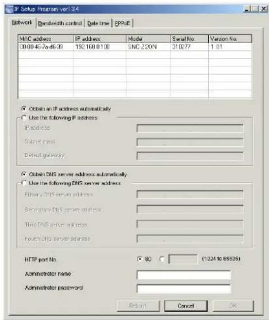
6 Click on the camera you want to assign a new IP address in the list. The network settings for the selected camera are displayed.

7 Set the IP address.
To obtain the IP address automatically from a DHCP server:
Select Obtain an IP address automatically.
The IP address, Subnet mask and Default gateway are assigned automatically.
To specify the IP address manually:
Select Use the following IP address, and type the IP address, Subnet mask and Default gateway in each box.
Note
When you select Obtain an IP address automatically, make sure that the DHCP server is operating on the network.
8 Set the primary DNS server address and, if necessary, secondary DNS server address.
To obtain the DNS server addresses automatically:
Select Obtain DNS server address automatically.
To specify the DNS server addresses manually: Select Use the following DNS server address, and type the Primary DNS server address and Secondary DNS server address in each box.
Note
The Third DNS server address and Fourth DNS server address are invalid for this camera.
9 Set the HTTP port number.
Normally select 80 for the HTTP port number. To use another port number, select the text box and type a port number between 1024 and 65535.
10 Type the Administrator name and Administrator password.
The default settings of both items are "admin."
Note
You cannot change the Administrator name and Administrator password in this step. To change these items, see “Setting the User — User setting Page” on page 25.
11 Confirm that all items are correctly set, then click OK.
If “Setting OK” is displayed, the IP address is correctly assigned.
Tip
The factory setting of the camera network is as follows.
IP address: 192.168.0.100
Subnet mask: 255.0.0.0
Wireless LAN setting
Type: 802.11 Ad hoc mode
SSID: snc-z20
Channel: 11 ch
WEP: Off
IP address: 10.0.0.100
Subnet mask: 255.0.0.0
Changing the Communication Bandwidth
1 Click the Bandwidth control tab to display the bandwidth setting window. The current bandwidth is displayed in Current bandwidth.
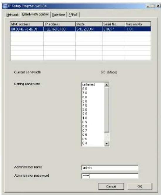
2 Click to select the desired bandwidth from the Setting bandwidth list box.
3 Type the Administrator name and Administrator password in each box.
4 Click OK.
If "Setting OK" is displayed, the bandwidth setting is completed.
Setting the Date and Time
You can set the date and time on the camera.
1 Click the Date time tab to display the date/time setting window.
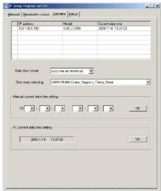
2 Click to select the camera you want to set the date and time for.
You can select multiple cameras and set the date and time simultaneously.
3 Select the date/time format from the Date time format drop-down list.
4 Select the area where the camera is installed from the Time zone selecting drop-down list.
5 Set the date and time. You can set the date and time in two ways.
Manual setting
Set the current date and time on the Manual current date time setting boxes, and click OK. The setting boxes are for the year (lower two digits), month, date, hour, minutes and seconds from left to right.
Using the computer's date and time
The date and time set on the computer is displayed in the PC current date time setting box.
Click OK on the right to set the camera's date and time to the displayed computer's date and time.
Note
Due to the network properties, there may be a slight difference between the displayed computer's date and time and those set on the camera.
Rebooting the Camera
Click Reboot on the Network tab to reboot the camera. It will take about 10 to 20 seconds to reboot.
Assigning the IP Address to the Camera Using ARP Commands
This section explains how to assign an IP address to the camera using ARP (Address Resolution Protocol) commands without using the supplied setup program.
Note
When you turn on the camera, execute the ARP and PING commands within 5 minutes. Also when you restart the camera, execute the operation within 5 minutes.
1 Open the DOS window on the computer.
2 Enter the IP address and the MAC address of the camera you want assign a new IP address to, using the following ARP commands.
arp -s <Camera's IP address> <Camera's MAC address>
ping -t <Camera's IP address>
Example:
arp -s 192.168.0.100 08-00-46-21-00-00
ping -t 192.168.0.100
3 When the following line is displayed on the DOS window, hold down Ctrl and press C.
Reply from 192.168.0.100:bytes=32 time...
You will normally receive the reply after about 5 repetitions of "Request time out."
4 Wait until the execution of PING finishes, then input the following code.
arp -d 192.168.0.100
Note
If you do not receive the reply, check the following:
– Did you enter the ARP commands within 5 minutes after the camera was turned on?
If not, turn off the camera and restart the operation.
- Is the NETWORK indicator on the camera flashing? If the indicator goes off, the network connection has a problem. Connect the network correctly.
– Did you enter the IP address previously used for another device?
Assign a new IP address to the camera.
- Do the computer and the camera have the same network address?
If not, set the same network address on the computer and the camera.
Using the SNMP
This unit supports SNMP (Simple Network Management Protocol). You can read MIB-2 objects and write some MIB-2 objects using software such as SNMP manager software. This unit also supports the coldStart trap which occurs when the power is turned on or the unit restarts, and the Authentication failure trap which informs of an illegal access using SNMP. Using CGI commands, you can set community name and access limitation, reading/writing right, host to send traps, and some MIB-2 objects. To allow these settings, you need Level 4 authentication (the right to open the setting pages).
1. Inquiry Commands
You can check the SNMP Agent settings using the following CGI commands.
With the above inquiry, you can obtain the following setting information. The following explains the setting information using the inqjs=snmp (JavaScript parameter) format.
var sysDescr="\"SONY Network Camera SNC-RZ30\"" ...①
var sysObjectID="1.3.6.1.4.1.122.8501" ...②
var sysLocation="\"" ...③
var sysContact="\"” ...④
var sysName="\"" ...⑤
var snmpEnableAuthenTraps="1" ...⑥
var community="public,0.0.0.0,read,1" ...⑦
var community="private,192.168.0.101,write,2" ...⑧
var trap="public,192.168.0.101.1" ...⑨
①describes the instance of “mib-2.system.sysDescr.0”. You cannot change this parameter.
②describes the instance of "mib-2.system.sysObjectID.0". You cannot change this parameter.
③describes the instance of “mib-2.system.sysLocation.0”. This field is used to describe the information on the location of this camera. Nothing is set at the factory.
④describes the instance of “mib-2.system.sysContact.0”. This field is used to describe the information on the administrator of this camera. Nothing is set at the factory.
⑤describes the instance of “mib-2.system.sysName.0”. This field is used to describe the administration node of this camera. Nothing is set at the factory.
⑥describes the instance of “mib-2.snmpEnable AuthenTraps.0”. This example shows when “1” (enable) is set. With this setting, a trap occurs when there is an Authentication failure. When “2” (disable) is set, no Authentication failure trap occurs.
⑦describes the community name and the reading/writing attributes. This example shows the identification number “ID=1”, the community name public, and enables read from any IP address (0.0.0.0).
⑧describes the community name and the reading/writing attributes, similarly to ⑦. This example shows the identification number ID=2, the community name “private”, and enables “read/write” by the SNMP request packet from the host “192.168.0.101”.
⑨describes the host name to send a trap. This example shows the identification number “ID=1”, the community name “public”, and enables sending of traps to the host having the IP address “192.168.0.101”.
2. Setting Commands
The unit supports the following setting commands of SNMP.
First, perform the settings of the following parameters.
1) sysLocation=
2) sysContact=

the
3) sysName=
Set the instance of “mib-2.system.sysName.0” in the
4) enaAuthTraps=
Set the instance value of “mib-2.snmp.snmp
EnableAuthenTraps.0” in the
5) community=
Example: To allow reading/writing any host in the “private” community and having the ID number “2”. community=2,w,private,0.0.0.0
6) trap=
Set the host you want to send traps to.
Example: To specify the destination of traps as the private community and the ID number “1”. rap=1,public,196.168.0.101
7) delcommunity=
This parameter is used to delete the previous community setting.
8) deltrap=
This parameter is used to delete the previous setting of the host to send traps to.
When you have finished changing the SNMP setting information, check the changed settings using an inquiry command. If the changed settings are OK, restart the SNMP using the following CGI command. Be careful that by entering the command, the camera enters the restart mode.
SNMP restart command
GET, POST
http://ip_adr/snmpdconf/snmpdconf.cgi?snmpd=restart
Storing an HTML File in the Built-in Flash Memory
You can display the favorite homepage that you have created when you enter the IP address of the camera in the Address box of the browser.
This section explains how to store the HTML file of the homepage created using the CGI commands in the built-in flash memory.
To select the display of the created homepage, see "Default URL" on page 15.
Notes
- Administrator access rights are required for this operation.
- The file size of the homepage to be stored in the flash memory should be 2.0 MB or less.
- The free space of the built-in memory should be 2.5 MB or more.
- Disable the Image memory function (page 35).
- Make sure that a firewall, etc. is not blocking the HTTP port and FTP port. (If you are not sure, consult your network administrator.)
- When you finish storing in the flash memory, the camera will restart automatically. Do not turn off the power of the camera until the camera has restarted completely.
1 Insert the supplied CD-ROM disc into your CD-ROM drive.
2 Double-click the Homepage folder in the CD-ROM drive.
3 Double-click CustomHomepageInstaller.exe. The installer starts and notes are displayed.
When you are using Windows Vista, message "User Account Control – An unidentified program wants access to your computer" may appear. In this case, click Allow.
4 Read the notes carefully, and click Next. The Software License Agreement is displayed.
5 Read the agreement carefully, select Agree if you accept it, then click Next.
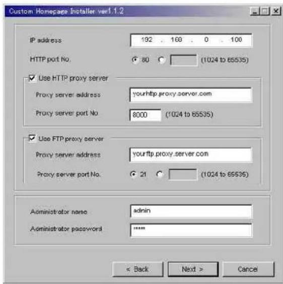
6 Type the IP address of the camera in the IP address box.
7 Specify the HTTP port No. of the camera.
8 When you use a proxy server, set the following: For the proxy server of your environments, consult your network administrator.
When using an HTTP proxy server:
Select Use HTTP proxy server, and type your settings in the Proxy server address and Proxy server port No. boxes.
When using an FTP proxy server:
Select Use FTP proxy server, and type your settings in the Proxy server address and Proxy server port No. boxes.
Note
If you cannot establish communication with the camera with the proxy server being used, connect the camera to the local network and run the installer without using the proxy server.
9 Type the Administrator name and Administrator password.
10 Confirm that all items are correct, then click Next.
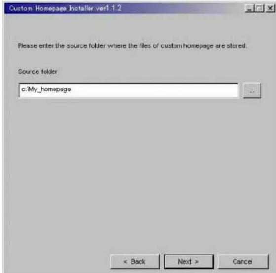
11 Type the path for the folder in which your homepage is stored in the Source folder box, then click Next.
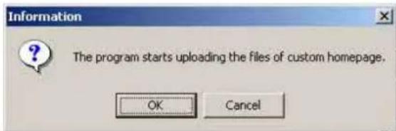
12 Click OK. Uploading of the homepage file starts.
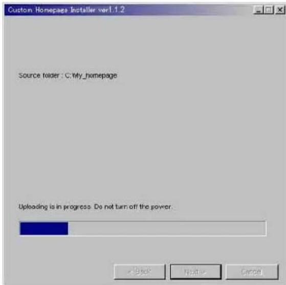
The following page will appear after a while. The camera will be restarted automatically in two minutes, and storing to the built-in flash memory is completed.
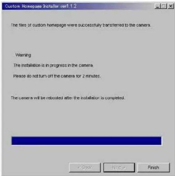
13 Click Finish to exit the program.
When using Windows XP Service Pack 2
Installing software
A warning message regarding the active contents may appear when you install software such as IP Setup Program from CD-ROM. In this case, operate as follows:
Example: In case of IP Setup Program
If message "Internet Explorer" appears, click Yes.
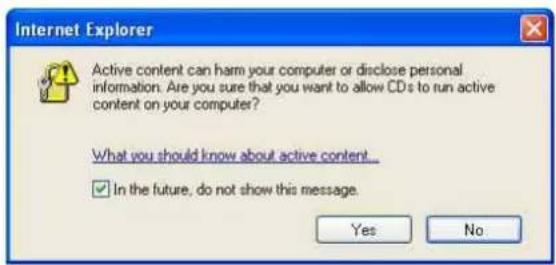
If message "File Download – Security Warning" appears, click Run.
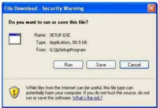
Note
If you select Save in the "File Download – Security Warning" dialog, you will not be able to perform installation correctly. Delete the downloaded file, and click the Setup icon again.
If message "Internet Explorer – Security Warning" appears, click Run.
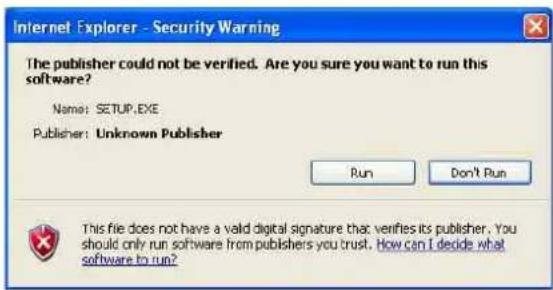
The software installation starts.
Installing ActiveX Control
During installation of ActiveX Control, the information bar or "Security Warning" may appear. In this case, operate as follows:
If message "Information Bar" appears, click OK.
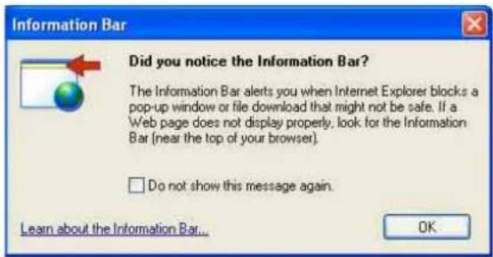
If the information bar appears, click on the bar and select Install ActiveX Control....
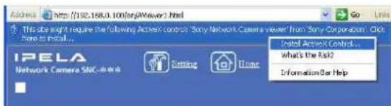
If "Internet Explorer – Security Warning" appears, click Install.
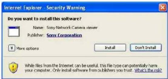
The installation of ActiveX Control starts. When installation is completed, the main viewer or the Activity detection setting page appears.
Configuring Windows Firewall
The IP Setup Program may not operate correctly depending on the configuration of Windows Firewall. (No cameras are shown in the list even if they are detected.) In this case, confirm the Windows Firewall configuration as follows:
Example: In case of IP Setup Program
1 Select Control Panel from the Start menu of Windows.
2 Select Security Center of the working field.
3 Select Windows Firewall and select Off in the Windows Firewall dialog.
![Windows Firewall General Exceptions Advanced Windows Firewall is helping to protect your PC Windows Firewall helps protect your computer by preventing unauthorized users from gaining access to your computer through the Internet or a network. On [recommended] This setting blocks all outside sources from connecting to this computer, with the exception of those selected on the Exceptions tab. Don't allow exceptions Select this when you connect to public networks in less secure locations, such as airports. You will not be notified when Windows Firewall blocks programs. Selections on the Exceptions tab will be ignored. Off [not recommended] Avoid using this setting. Turning off Windows Firewall may make this computer more vulnerable to viruses and intruders. What else should I know about Windows Firewall? OK Cancel](/content/2026/05/920516/images/f1e95354286ec0028a4291a1411e02e074fc8823de0d648950b451ebc3b6d291.jpg)
The cameras will be displayed in the list.
If you want to keep Windows Firewall On, continue with the following steps.
4 Select the "Exceptions" tab.
5 Select Add Program....
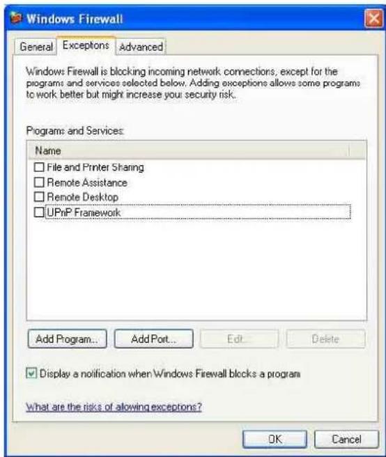
6 In the Add Program dialog, select IP Setup Program and click OK.
Then the IP Setup Program is added to the Programs and Services list.
7 Click OK.
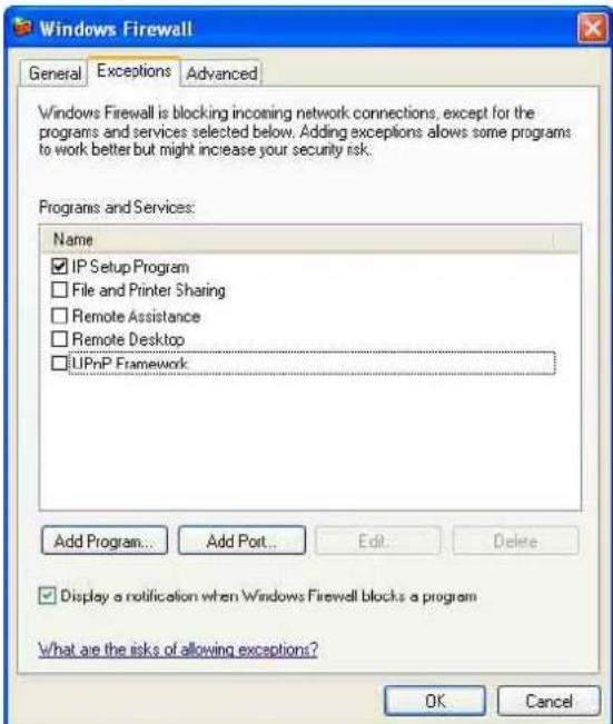
When the above procedure is completed, the cameras connected in the local network are displayed in the IP Setup Program.
When using Windows Vista
Installing software
A warning message regarding the active contents may appear when you install software such as IP Setup Program from CD-ROM. In this case, operate as follows:
Example: In case of IP Setup Program
If pop-up "AutoPlay" appears when a CD-ROM is inserted into the CD-ROM drive, click Open folder to view files.
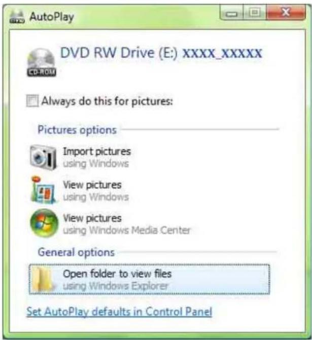
If message "User Account Control – An unidentified program wants access to your computer" appear, click Allow.
The software installation starts.
Starting the software
When you start software such as IP Setup Program, message "User Account Control – An unidentified program wants access to your computer" may appear. In this case, click Allow.
Installing ActiveX Control
During installation of ActiveX Control, the information bar or "Security Warning" may appear. In this case, operate as follows:
If message "Information Bar" appears, click OK.
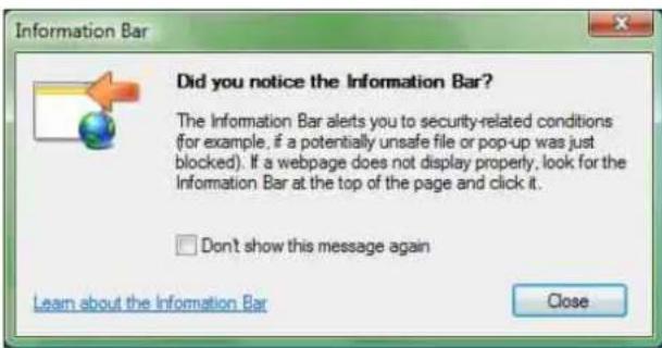
If the information bar appears, click on the bar and select Install ActiveX Control....
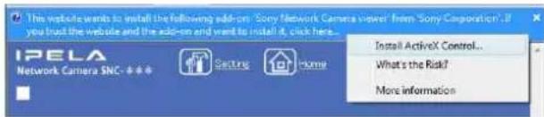
If message "User Account Control – Windows needs your permission to continue" appear, click Continue.
If "Internet Explorer – Security Warning" appears, click Install.
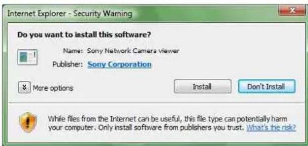
The installation of ActiveX Control starts. When installation is completed, the main viewer or the Activity detection setting page appears.
Configuring Windows Firewall
The IP Setup Program may not operate correctly depending on the configuration of Windows Firewall. (No cameras are shown in the list even if they are detected.) In this case, confirm the Windows Firewall configuration as follows:
Example: In case of IP Setup Program
1 Select Control Panel from the Start menu of Windows.
2 Click Windows Firewall.
3 Select Turn Windows Firewall on or off.
"User Account Control – Windows needs your permission to continue" may appear. In this case, click Continue.
4 Select Off in the "General" tab.
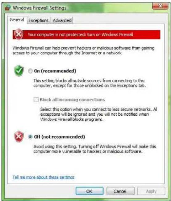
The cameras will be displayed in the list. If you want to keep Windows Firewall On, continue with the following steps.
5 Select the "Exceptions" tab.
6 Select Add Program....
7 If the Add Program dialog appears, select IP Setup Program and click OK.
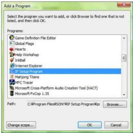
Then the IP Setup Program is added to the Program or port list.
8 Click OK.
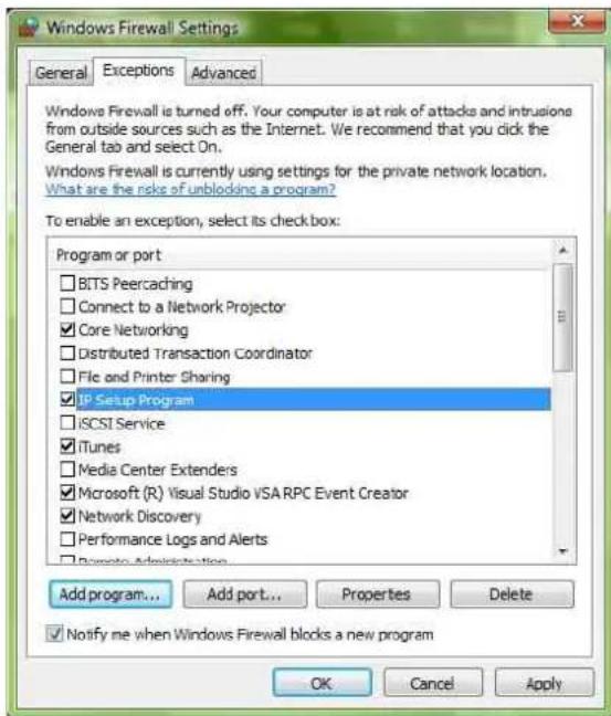
When the above procedure is completed, the cameras connected in the local network are displayed in the IP Setup Program.

Others
Index
Numerics
802.11 Ad hoc mode .....23
A
access log 15
access right 26
ActiveX control.... 51, 53
ActiveX viewer....7
activity detection function......41
administrator 6
administrator menu page ......13
alarm.... 28, 33, 34, 37
alarm buffer 39
alarm out....34
alarm output ......12
application menu ....13
Apply button....14
ARP commands....46
ATA memory card 1215
B
Back button 14
backlight compensation....19
backup 29
basic menu....13
baud rate ....40
built-in memory....12
C
camera control parts ....10
camera operation time ....15
camera setting....17
Cancel button....14
capture 12
CGI commands.... 15, 47, 49
character length 40
color....18
common buttons ....14
communication bandwidth. 22, 23, 45
contrast 20
Custom Homepage Installer..... 15, 49
D
date and time 16,45
day/night mode.... 12, 20
default gateway.... 21, 22
DHCP 21, 22
digest viewer....30
DNS server 22
downloading images....31
E
electronic shutter ....19
electronic zoom ....10
E-mail 11,32
E-mail address....24
e-mail address....24
exclusive control mode......15
exposure....19
exposure compensation ....20
F
F number ......19
factory settings ......17
flash memory....15,49
flip 18
focus mode ....19
focusing 10
format of date and time .....16
frame rate....8,9,15
FTP client function....27
FTP server 11,27
FTP server function....31
G
gain 19
H
HTML file 15,49
HTTP....24,39
HTTP server 23
|
image control section ..... 8, 9, 10, 11
image memory function ....35
image quality ....18
image size.... 9,17
information bar....51
Information Bar message ....51
infrastructure mode ....23
Internet Explorer 6
IP address 6,21,22,43
IP address notification....24
IP Setup Program....43
iris....19
J
Java....7
Java applet viewer ....7
L
loading the setting data....17
logging in....6
login page 6
M
MAC address 21, 22
main viewer page....8
manual focusing ......21
maximum wait number......15
memory....35
menu section......8
monitor image section 9
monochrome....18
mouse....11, 21
N
network configuration ......21
NTP server....16
0
OK button 14
optical zoom 10
overwrite....36
P
parity bit ....40
password....25
pop-up....42
port number 23
post-alarm....39
pre-alarm 39
proxy server....24
R
reboot....17,45
recording a still image ....12
recording images ....35
reset 20
s
saturation.... 20
saves the setting data.... 17
schedule 40
security function 26
security setting 26
Security Warning 51, 53
sending a still image 11
sending images.... 27, 32
sensitivity 41
serial number.... 14
serial port 39
setup program 43
sharpness.... 20
SMTP 24
SMTP function.... 32
SMTP server 24
SNMP 47
software version 15
SSID.... 23
stop bit.... 40
subject 24
subnet mask.... 21, 22
system configuring.... 14
T
TCP 39
TCP port.... 40
time difference 16
title 24
title bar 14
trigger control parts.... 11
trimming.... 18
U
URL 15
user authentication 26
user name 25
user setting 25
V
view size....9
viewer....7
VISCA 39
W
welcome page.... 6, 14
WEP 23
WEP key 23
white balance mode.... 19
Windows Firewall 52
Windows Vista 53
Windows XP Service Pack 2...... 51
wireless LAN card 22
wireless network 22
Z
zoom bar....9,11
zoom mode.... 19
zooming....10, 11, 21
zooming position.... 20
- Operating the Camera
- Administrating the Camera
- Others
- Using the Supplied Setup Program .... 43
- Assigning the IP Address to the Camera Using
- ARP Commands 46
- Using the SNMP 47
- Storing an HTML File in the Built-in Flash
- Memory 49
- When using Windows Vista 53
- Index 56
- Overview
- NOTICE TO USERS
- Phenomena Specific to CCD Image Sensors
- White flecks
- Vertical smear
- Aliasing
- How to Use This User's Guide
- Jumping to the related page
- Software display examples
- Printing the User's Guide
- Installation Manual (printed matter)
- Logging in to Homepage — Welcome Page
- Logging in as a User
- Note
- When using antivirus software in the computer
- Logging in as Administrator
- Select the viewer.
- Other functions on the welcome page for Administrator
- Setting
- Home
- About Viewers
- Java applet viewer
- To check the Java version
- To enable Java Plug-in
- To install Java Plug-in
- ActiveX viewer
- Notes
- Tip
- Configuration of Main Viewer Page
- Menu Section
- Control
- Capture
- Trigger
- Frame rate
- View size
- Camera control parts
- Trigger control parts
- Monitor Image Section
- Zoom Bar
- Controlling the Monitor Image
- Image control section
- Selecting the frame rate
- Selecting the view size
- Operating the Camera from the Image Control Section
- Image control section (camera control parts)
- Zooming
- WIDE
- TELE
- DZOOM X2
- DZOOM X1
- About the zoom range
- Focusing
- NEAR
- FAR
- ONE PUSH AF
- Operating the Camera from the Monitor Image
- Zooming Using the Center Wheel of the Mouse
- Zooming Using the Zoom Bar
- Controlling the Application Manually
- Sending a Still Image File to an FTP Server
- Sending a Still Image via E-mail
- Recording a Still Image on an ATA Memory Card or the Built-in Memory of the Camera
- Controlling Alarm Output
- Selecting the Day/Night Mode
- Capturing a Monitor Image
- To save the captured image
- Configuration of Administrator Menu Page
- Basic menu
- System
- Camera
- Network
- User
- Security
- Application menu
- FTP client
- FTP server
- SMTP
- Alarm out 1
- Alarm out 2
- Image memory
- Alarm buffer
- Serial
- Schedule
- Activity detection
- Pop-up
- Buttons common to every setting page
- General notes on setting pages
- Configuring the System — System setting Page
- System setting Section
- / index.html
- Title bar name
- Welcome text
- Serial No.
- Default frame rate
- Default URL
- To display the homepage built in the camera Select /index.html.
- To display your individual homepage
- A-slot (adrv)
- Flash memory (ddrv)
- Exclusive control mode.
- Operation time
- Maximum wait number
- System log
- Access log
- Date time setting Section
- Current date time
- System (PC) current date time
- Manual current date time
- Time zone selecting
- Date time format
- Synchronization with NTP server
- NTP server name
- Interval time
- Initialization Section
- Backup setting
- Restore setting
- Reboot
- Factory default
- Setting the Camera — Camera setting Page
- Camera setting Section
- Image size
- Image quality
- Image Flip
- Image
- Area setting
- Select mode
- To trim an image
- When Random is selected:
- Zoom mode
- Focus mode
- White balance mode
- Exposure mode
- Back light compensation
- Shutter
- Iris
- Gain
- Exposure compensation
- Saturation
- Sharpness
- Contrast
- Camera reset
- Zoom Position
- Day/Night setting Section
- Day/Night mode
- Schedule No.
- OK/Cancel
- Camera control mode setting Section
- Mode
- Level
- Configuring the Network — Network setting Page
- Wired LAN setting Section
- DHCP
- DNS auto acquisition
- IP address
- Subnet mask
- Default gateway
- MAC address
- Primary DNS
- Secondary DNS
- Bandwidth control
- Wireless LAN setting Section
- Verified wireless LAN adapter card
- SSID
- Type
- WEP
- WEP key data
- HTTP port setting Section
- HTTP port No.
- Notifying the IP Address — Dynamic IP address notification Section
- SMTP server name
- Recipient e-mail address
- From e-mail address
- Subject
- Message
- HTTP
- URL
- Proxy server name
- Proxy port No.
- Method
- About the special tags
- Setting the User — User setting Page
- Administrator, User 1 to 9
- User name
- Password
- Re-type password
- Access right
- User access right
- Setting the Security — Security setting Page
- Activating/Deactivating the Security Function — Security usage setting Page
- Setting the Security Function —Securing setting Page
- Default policy
- Network address/Subnet 1 to Network address/Subnet 10
- Sending Images to FTP Server
- — FTP client setting Page
- Activating/Deactivating the FTP Client Function
- — FTP client usage setting Page
- Setting the FTP Client Function — FTP client setting Page
- FTP server name
- Remote path
- Image file name
- Suffix
- Sequence No. clear
- Back/OK
- Alarm mode setting Section
- Alarm
- Available period
- Alarm buffer configuration
- Digest viewer
- Periodical sending mode setting Section
- Backup sending mode
- Backup interval time
- Built-in memory
- Log
- Operating the Digest Viewer
- Number
- Date
- Image view size
- Play speed
- Play
- Next
- Prev (previous)
- Still
- Stop
- Downloading Images from the Camera — FTP server setting Page
- Activating/Deactivating the FTP Server Function — FTP server usage setting Page
- Setting the FTP Server Function — FTP server setting Page
- Selected root directory
- User ID
- Sending an Image via E-mail — SMTP setting Page
- Activating/Deactivating the SMTP Function — SMTP usage setting Page
- Setting the SMTP Function — SMTP setting Page
- Administrator e-mail address
- Setting the Alarm Out 1 or 2
- — Alarm out 1 or 2 setting Page
- Activating/Deactivating the Alarm Out 1 Function
- — Alarm out 1 usage setting Page
- Setting the Alarm Out 1 Function — Alarm out 1 setting Page
- Alarm duration
- Timer mode setting Section
- Recording Images in Memory
- — Image memory setting Page
- Activating/Deactivating the Image Memory Function — Image memory usage setting Page
- A-slot
- Use image memory function/Do not use image memory function
- Memory
- Recording an Image in the Selected Memory — Image memory setting Page
- Overwrite
- Capacity warning
- Periodical recording mode setting Section
- Directory Structure of Image Memory
- Setting the Alarm Buffer — Alarm buffer setting Page
- Recording interval
- Pre-alarm images
- Post-alarm images
- Maximum alarm images
- Communicating Data via Serial Port
- — Serial setting Page
- TCP port No.
- Baud rate
- Parity bit
- Character length
- Stop bits
- Setting the Schedule — Schedule setting Page
- Schedule No. 1 to Schedule No. 6
- Setting the Activity Detection Function — Activity detection setting Page
- Sensitivity
- Setting the Activity Detection Area
- Showing the Pop-up — Pop-up setting Page
- Manual pop-up text
- Alarm pop-up text
- Display mode
- Sensor/Activity detection
- Using the Supplied Setup Program
- Assigning the IP Address Using the Setup Program
- To obtain the IP address automatically from a DHCP server:
- To specify the IP address manually:
- To obtain the DNS server addresses automatically:
- Wireless LAN setting
- Changing the Communication Bandwidth
- Setting the Date and Time
- Manual setting
- Using the computer's date and time
- Rebooting the Camera
- Assigning the IP Address to the Camera Using ARP Commands
- Using the SNMP
- Inquiry Commands
- Setting Commands
- SNMP restart command
- Storing an HTML File in the Built-in Flash Memory
- When using an HTTP proxy server:
- When using an FTP proxy server:
- When using Windows XP Service Pack 2
- Installing software
- Installing ActiveX Control
- Configuring Windows Firewall
- When using Windows Vista
- Starting the software
- Index
- Numerics
- A
- B
- C
- D
- E
- F
- G
- H
- |
- J
- L
- M
- N
- 0
- P
- R
- s
- T
- U
- V
- W
- Z
Brand : SONY
Model : SNC-Z20N
Category : Security Camera