Jive 200 E - Garage door opener Sommer - Free user manual and instructions
Find the device manual for free Jive 200 E Sommer in PDF.


| Product Type | Garage Door Opener |
| Brand | Sommer |
| Model | Jive 200 E |
| Application | For swing gates (1 or 2 wings) |
| Packaging Dimensions (L x W x H) | 800 x 200 x 220 mm |
| Weight (1 wing / 2 wing) | 30.5 kg / 58.5 kg |
| Rated Voltage | 220-240 V AC, 50 Hz |
| Motor Voltage | Approx. 30 V DC |
| Power Consumption (Stand-by / Operation) | 2 W / up to 100 W |
| Protection Class (Drive / Control Unit) | IP44 / IP54 |
| Operating Temperature (Drive / Control Unit) | -10°C to +70°C / -20°C to +70°C |
| Travel | 370 Nm |
| Max Gate Wing Dimensions (Length / Height / Weight) | 2.0 m / 2.5 m / 200 kg |
| Min Free Surface | 50% |
| Functions | Limit switch auto stop, self-locking, force monitoring, remote control (up to 112 codes) |
| Safety Features | Force cut-off, emergency release, optional light barrier/contact strip |
| Maintenance | Regular inspection of fittings (screws), safety devices every 4 weeks; yearly professional check |
| Spare Parts | Only original manufacturer parts; warranty excludes batteries, fuses, bulbs |
| General Information | EU Declaration of Conformity; installation by qualified electrician required |
Frequently Asked Questions - Jive 200 E Sommer
User questions about Jive 200 E Sommer
0 question about this device. Answer the ones you know or ask your own.
Ask a new question about this device
Download the instructions for your Garage door opener in PDF format for free! Find your manual Jive 200 E - Sommer and take your electronic device back in hand. On this page are published all the documents necessary for the use of your device. Jive 200 E by Sommer.
USER MANUAL Jive 200 E Sommer
natural_image
3D technical illustration of a mechanical assembly with a lever and mounting base (no text or symbols)jive 200 E

Installation and operating instructions
1 - 2 3

Contents
General information....2
Symbols2
Safety instructions 2
Normal use 2
Permitted gate wing dimensions 3
Technical data 3
Dimensions 3
Functions 3
EU Manufacturer's Declaration 3
Installation 4
Safety instructions 4
Supplied components 5
Location of installation 5
Installation of gate wing fittings 6
Installation of control unit 6
Connecting to power supply (230V) 7
Connecting the operator to the control unit 7
Checking direction of movement 7
Adjusting end stops 8
Commissioning 9
General instructions 9
Preparation for standard operation 9
Activating standard operation 9
Adjusting force tolerance 10
Programming of remote control 10
Operation and use....11
Opening and closing gate 11
Resetting control 11
Emergency release in the event of a power failure 12
Opening foundation box 12
4-channel radio receiver 12
Programming of remote control 13
Additional functions and connections.... 14
LEDs 14
DIL switch 15
Automatic close mode 15
Potential-free relay contact 16
Connecting safety devices 16
Connecting keys 16
Connecting drives 16
Connecting to power supply (230V) 17
Accessories 18
Maintenance....20
Regular inspections 20
Service and warranty 20
Disassembly....20
Troubleshooting....21
Tips for troubleshooting 21
Spare parts list / Glossary 23
Wiring diagram....25
EU declaration of conformity
The company
herewith declares that the product named below, if operated properly, conforms to the general requirements according to Article 3 of the R&TTE Directive 1999/5/EC and fulfils the requirements of the standards listed below:
Product: RF Remote Control for Doors & Gates
Type: RMO4-868-2, RM03-868-4, RX01-868-2/4,
RFSDT-868-1, RFSW-868-1, RM02-868-2,
RM06-868-2, RM04-868-1, RM02-868-2-TIGA, RM08-868-2,
RM01-868, RM02-434-2, Rm03-434-4, RM04-434-2
Applicable guidelines and standards are:
- ETSI EN 300220-1:09-2000, -3:09-2000
- ETSI EN 301489-1:07-2004, -3:08-2002
- DIN EN 60950-1:03-2003
Indicates a potential risk.
Indicates a potential risk. Failure to comply with the instructions may result in serious injury or damage to property!

Information, useful advice.


Refers to the relevant illustration in the introduction or the main text of this manual.
Safety instructions
General safety instructions
- All persons in charge of the installation, maintenance or operation of the drive system must have read and fully understood these instructions.
- Keep this installation and operating manual near the unit for future reference.
• After installation and commissioning, all persons operating the drive must be instructed on its functions and proper operation. - All persons in charge of the installation, maintenance or operation of the drive system must have read and fully understood these instructions.
• Always comply with the statutory health and safety regulations and the applicable standards. - The installation and operation of the drive system is governed by the following standards: EN 12 453, EN 12 604, EN 12 605, etc.
- There is a risk of injury from crushing at the closing edges of the gates or near the mechanical parts.
- Never operate the drive if you suspect that it might be faulty or damaged.
- Prior to any work at the gate or drive, disconnect drive system from the power supply and secure it against inadvertent reconnection or actuation.
- Use only original spare parts, accessories and fixtures supplied by the manufacturer.
Operation
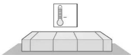
- The drive mechanism may only be stored indoors, in a dry, sealed environment at an ambient temperature of between -20^ and +50^ .
- Store drives in horizontal position.
natural_image
Simple line drawing of a thermometer placed on a rectangular block (no text or symbols)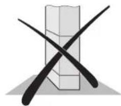
natural_image
Abstract graphic with two crossed black lines over a gray rectangular box (no text or symbols)Operation
- The drive mechanism may only be operated, if a risk-free force tolerance has been set. The force tolerance must be set as low as possible in order to ensure that the door's closing force does not constitute a danger, see section "Testing force settings".
- Never reach into the gate or any of its moving parts.
- Only drive through the gate after it has been fully opened.
- Ensure that the drive is never operated by children or persons who have not been specifically instructed.
- When operating the gate, ensure that there are no persons, especially children, animals or objects within its operating range.
- Only operate the gate with the remote control device when you have full view of the gate.
- Regularly inspect the safety devices. Immediately repair damaged or defective parts. For details, see maintenance instructions.
- At gates with automatic closing mechanism, all edges must be secured according to the applicable regulations and standards.
• Always remove the key to prevent unauthorised operation.
Radio remote control
- The radio remote control may only be used for equipment and systems in which defective remote operation of the transmitter or receiver does not constitute a risk to people, animals or property, or in cases where this risk is eliminated by means of additional safety facilities.
- All persons operating the gate must be instructed that systems, where there is a risk of injury or damage, may not be operated by remote control, or that such operation is only permitted, if all movements of the gate can be supervised.
- The radio remote control device may only be used, if the operator can fully supervise the movement of the device and if no persons or objects are within the movement range of the gate.
- Keep the remote control device out of reach of children or animals and prevent any inadvertent use.
- The operator of this radio-controlled equipment is not in any way protected against interference from other telecommunication systems and facilities (e.g. other radio-controlled equipment that is licensed to operate at the same frequency range). If such interference occurs, please contact the local radio and telecommunications authority requesting a radiolocation.
- Do not use hand-held transmitters near locations or installations that are susceptible to radio interference (e.g. airports, hospitals).
Rating plate
The rating plate is located on the cover of the control unit housing.
Normal use
After the drive system has been installed, the person responsible for the installation must complete an EU Declaration of Conformity according to Machine Directive 98/37/EU and attach a CE mark at the type plate of the drive. This also applies in cases where the owner of the system is a private person, as well as to manually operated gates that have been upgraded with a drive. The above documents and the instructions for installation and operation must be handed over to the operator.
- The drives are exclusively designed for the opening and closing of gates. Any other use is deemed improper. The manufacturer shall not be liable for damages resulting from improper use. The user accepts sole responsibility for any risks thereby incurred. Improper use shall void all warranty.
- Gates that are to be upgraded with an automatic drive system must comply with the applicable standards and directives as amended, e.g. EN 12 453, EN 12604, EN 12605.
- Maintain the safety distances between the gate and any nearby object as required by EN 12604.
- The drive system may only be operated if it is in proper working order. Always follow standard safety procedures and adhere to the instructions in this installation and operating manual.
- Immediately eliminate any defects that might impair the safety of the equipment.
• The gate wings must only have minimum play at the hinges. - The gate wings must be stable and warp-proof, i.e. they may not bend or warp during opening or closing operation.
- The DSTA24 control and jive 200 drive systems may only be operated in conjunction.
- The DSTA24 control and the jive 200 drives are designed for use in private premises.
- The electric drive may only be used for the opening and closing of gates with one or two wings.
General information
Permitted gate wing dimensions
- Length: max. 2,0 m
- Height: max. 2,5 m
- Weight: max. 200 kg
- Free surface: min. 50 %,
irrespective of gate wing size
- Slope: 0 %
Technical data
General 1 wing 2 wing
| Runtime approx. 10 ...25 | approx. 15 ...30 sec. | |
| Protection class | ||
| Drive | IP 44 | IP 44 |
| Control system housing | IP 54 | IP 54 |
| Rated voltage | 220 ...240 | 220 ...240 Volt |
| Rated frequency | 50 | 50 Hz |
| Operating temperature | ||
| Drive | -10 ...+70 | -10 ...+70 °C |
| Control system housing | -20 ...+70 | -20 ...+70 °C |
| Travel 370 | 370 Nm | |
| Operating factor: | 15 | 15 % |
Stand-by
| Rated current consumption | 10 | 10 | mA |
| Rated power consumption | 2 | 2 | W |
Rated operation
| Motor voltage: | ca. 30 | ca. 30 | V |
| Rated current consumption: | ca. 1,8 | ca. 3,6 | A |
| Rated power consumption: | ca. 50 | ca. 100 | W |
Workplace noise emission < 75 dBA - drive only
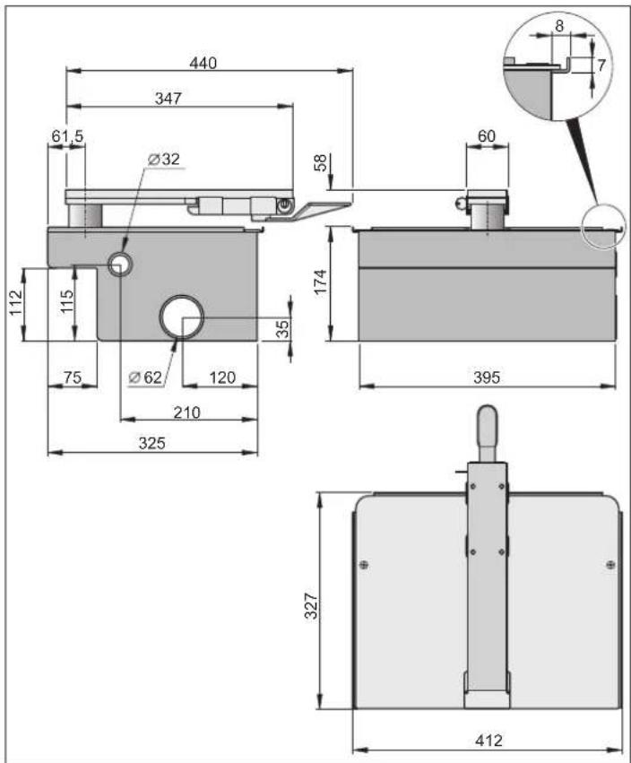
Dimensions
All dimensions in mm.
Functions
When the preset stop positions are reached, the drive is automatically switched off by means of limit switches.
Locking of gate
An electric lock can be mounted for additional safety.
The gate does not require a lock to be kept closed, as the drive mechanism is self-locking(with connection to the control system). The gate can thus not be forced open by hand without damaging the drive system or fittings.
Remote control
The drive can be operated by remote control with the supplied remote control transmitter, provided that the transmitter and the radio receiver have been properly programmed.
Safety devices
The control unit is equipped with an automatic force monitoring system. If there is more force required for opening or closing the gate as has been programmed during the programming run, the drive is set into reverse motion (gate direction "CLOSE") or halted (direction "OPEN").
The operator has the option to extend the control with various safety devices. For details see chapter additional functions and connections.
Examples of available accessories:
- Light barrier
• Safety contact unit with monitoring system
EU manufacturer's declaration
herewith declares that its drive system:
- jive 200 E
complies with the following Directives: - Machine Directive 98/37EU
- Low-Voltage Directive 73/23/EEC
- EU Directive on Electromagnetic Compatibility 89/336/EEC
The equipment fulfils the requirements of the following standards: - DIN EN 55014-1, DIN EN 55014-2, DIN EN 55022
- DIN EN 61000-3-2, DIN EN 61000-3-3, EN 60335-1/A14,
- E DIN VDE 0700 Teil 103, DIN V VDE 0801/A1, EN 12453
Note:
The gate system may not be commissioned until it has been established that the system in which the above drive is to be installed fulfils all specifications of the relevant EU Directives.
The power cable supplied with the control unit may only be used for the installation of the drive systems. After completion of the installation, disconnect the cable and replace it with a duct-laid cable. It is forbidden to use the supplied power cable for standard operation of the gate.

Caution!
Risk of damage to the system from voltage fluctuations
Voltage fluctuations caused by welding equipment, etc. can destroy the control system.
- Connect the control system only to the power mains after all installation work is completed.
- The control unit may only be connected to the power supply by a qualified electrician.
• Always comply with the instructions in this manual. - Locking devices (electrical keys, locking bolts, etc.) must be removed and disabled prior to installation of the dive system.
- Check the upper hinge for proper functioning. It should be adjustable, if possible.
- Ensure that the gate wings are properly secured to the posts as considerable forces are applied to the system during opening and closing.
- When carrying out welding work on the gate, cover the operator to prevent damage from sparks or weld splashes.
- If the gate is operated by means of a switch, it must be installed at a minimum height of 1.6 m above ground to prevent inadvertent activation by children.
- In public areas, use only approved fittings and securing devices (e.g. dowels).
Tips for installation
- Consult the operator when deciding on the location for installation of the control unit.
- Do not install the housing where it is visible from the street, in order to protect it against vandalism.
- For double-wing gates, install a centre stop.
The gate can be operated with a number of different control devices: Hand-held transmitter, Telecody, interior push-button and key switch. For the hand-held transmitter, Telecody and interior push-button, there is no need for cables as they are radio control devices. For more information, contact the supplier.
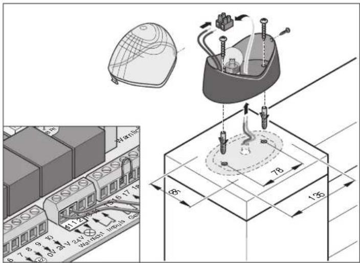
- Warning light 24 V
- Key switch (1 or 2 contact)
- Light barrier
- Connecting cables 7 m
- Main switch (lockable)
- Rod aerial (including cable)
- 24 V electric lock
- Telecody
- Holder for remote control device for installation in car or on wall
Installation
Supplied components
- Prior to installation, check delivery to ensure that it contains all necessary parts.
- Depending on the design of your drive system, the delivery might deviate from the standard delivery.
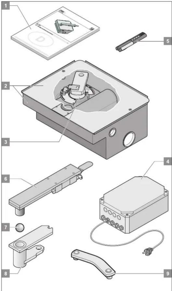
Complete installation kit 1 wing 2 wing
Weight 30.5 58.5 kg
Packaging (L x W x H): 800 x 200 x 220 mm
- Installation and operating instructions 1 x 1 x
- Foundation box with cover 1 x 2 x
- Drive unit including cables 1 x 2 x
-
Control system, in housing 1 x 1 x (with radio receiver, transformer and mains plug)
-
Remote control device including battery 1 x 1 x
Items 6, 7 + 8 are located in the foundation box (item 2).
- Gate hinge (incl. emergency release) 1 x 2 x
- Ball 1 x 2 x
- Gate bearing 1 x 2 x
- Lever 1 x 2 x
Location of installation
• Always install the operator in a horizontal position.
- Observe the position of installation of the motor.
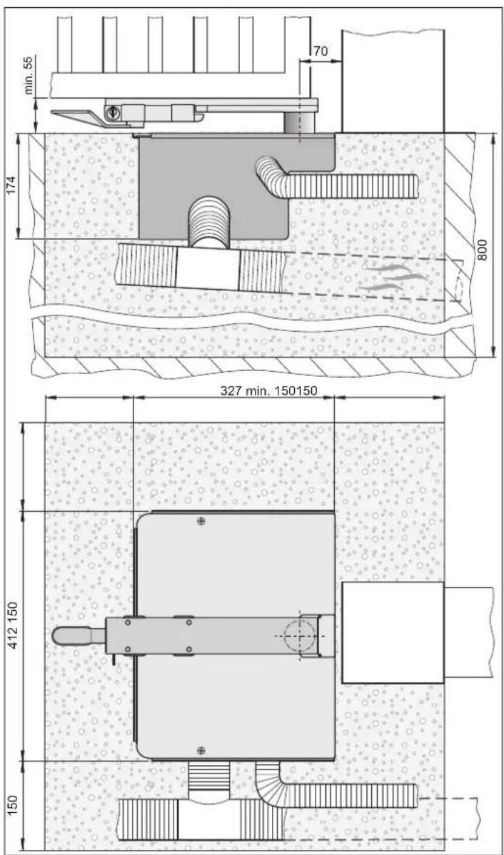
- Provide drain pipe for the drainage of the foundation box to prevent water collecting in the box.
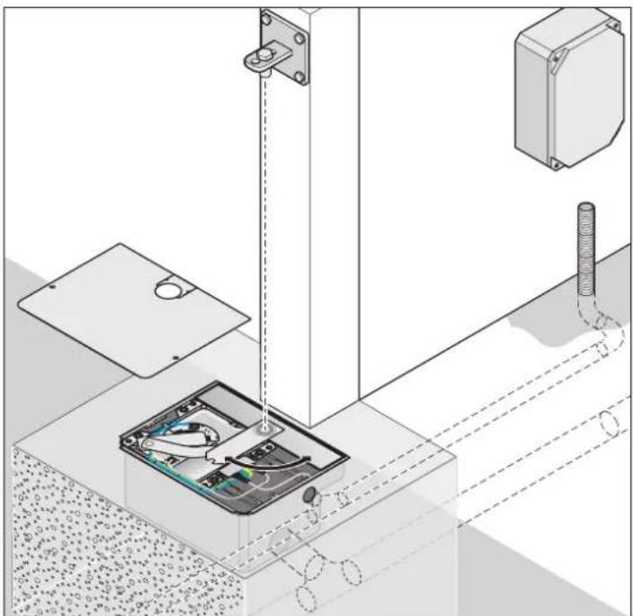
• Install all cables of the operator in conduits approved for the respective type of installation (e.g. installation in open ground).
- The foundation must extend to the frost-free depth (in Germany approx. 800mm), depending on local conditions and requirements.
• The foundation must be firm and level.
- For foundation dimensions, see figure.
Installation
The upper gate fitting must be horizontally aligned with the lower fitting. If this is not the case, the operator might become tensioned and eventually damaged. This can lead to failure of the operator.
natural_image
Technical diagram showing a mechanical assembly with labeled components and alignment lines (no readable text or symbols)Installation of gate wing fittings
Do not carry out any welding or grinding work after the fittings have been mounted, as residue from such work results in accelerated corrosion of the fittings and gate operator.
- When carrying out welding work on the gate, cover the operator to prevent damage from sparks or weld splashes.
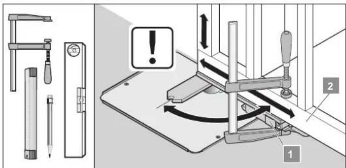
- Secure the fitting (1) with a vice to the gate (2) and manually open and close the gate to check the fitting's position (1). Adjust the position of the fitting, if required.
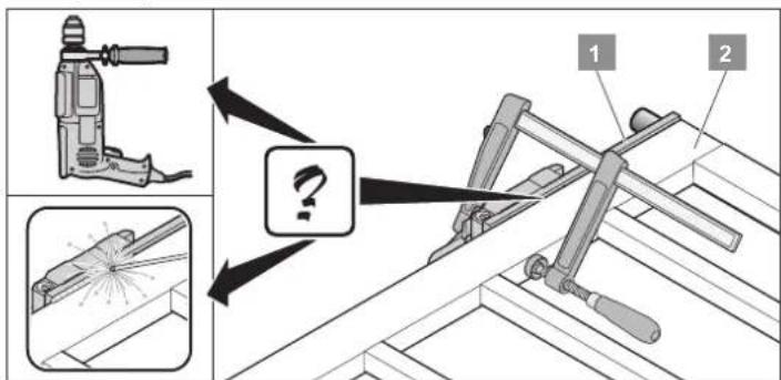
- If the fitting (1) is in the correct position, secure it to the gate (2) (welding, screwing).
† Check whether the gate wing can be easily opened and closed. If this is not the case, adjust the gate wing.
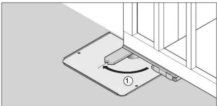
Locking the gate
natural_image
Technical diagram of a mechanical assembly with a rotating component and base plate (no text or symbols)- Engage the gate in the gate wing fitting (push against slight resistance)
natural_image
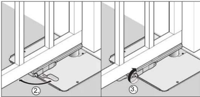
Technical diagram showing two mechanical assembly steps with numbered annotations (no text or symbols present)- Press the emergency release lever towards the gate until it engages. The gate is locked.
- Turn the key by 90° in anticlockwise direction. The emergency release lever is locked.
† The gate is now closed and locked.
Installation of control unit
The power cable supplied with the control unit may only be used for the installation of the drive systems. After completion of the installation, disconnect the cable and replace it with a duct-laid cable. It is forbidden to use the supplied power cable for standard operation of the gate.
i Establish power connection according to EN 12453 (all-pole disconnecting switch).
- Prior to carrying out any work at the control unit, disconnect it from the power supply.
- If there is humidity inside the housing, dry it with a blower.
- The control unit may only be connected to the power supply by a qualified electrician.
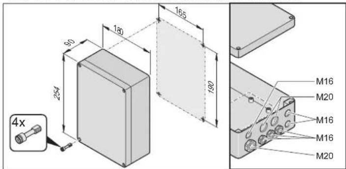
- Install control unit in upright position (cable ducts at base) and without applying any strain. The cover must fully close to prevent water from penetrating the housing.
- The cable ducts are designed for 1.5 ~mm^2 to 2.5 ~mm^2 cables. Do not use any other cables.
- Attach the housing at the intended fixing points; do not drill through the rear wall of the housing, as it might otherwise not be waterproof.
Installation
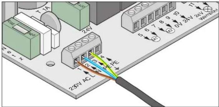
Connecting to power supply (230V)
Terminal Label Function
| 1 | L | Power conductor AC 230 V |
| 2 | N | Neutral conductor |
| 3 + 4 PE Earth conductor | ||
The connection to the power supply must be carried out by a qualified electrician.
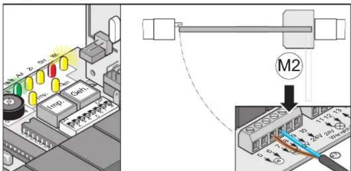
Connecting the operator to the control unit
Never connect drive to 230V power directly, as this would immediately destroy the motor.
Never connect the operator directly to the 230V power supply, as this would destroy the motor.
Single-wing gate
Double-wing gate
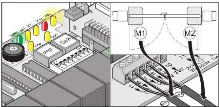
- Connect drive to control unit
- First connect and adjust drive at the wing with stop (M1), then install drive for pedestrian wing (M2)
- Set all DIL switches to OFF
- Set jumpers: single-wing or double-wing gate
- Connect control system to power supply. LED for power supply is on and "WL" LED flashes.
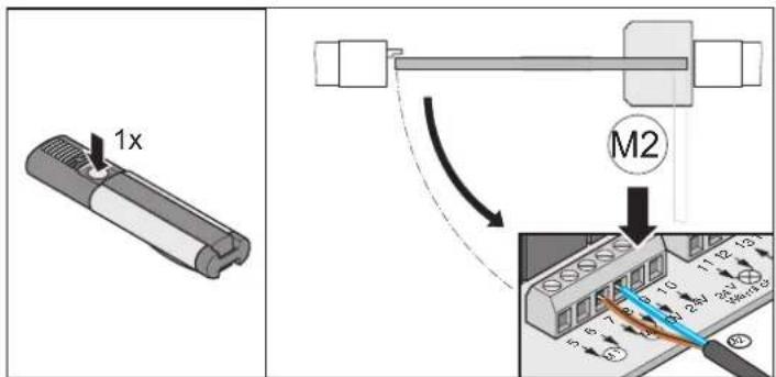
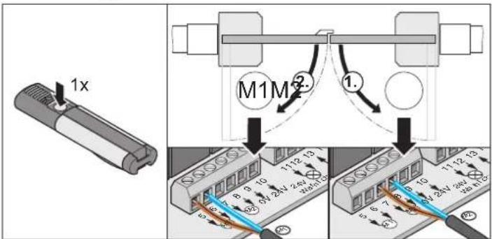
Checking direction of movement
- Upon the first command, the drives must move the gate in direction "OPEN". If this is not the case, exchange the connecting cables of the drive at the control unit.
Single-wing gate
Double-wing gate
Terminal Label Function
5 + 6 M1 single-wing gate: no function assigned
double-wing gate: connection for motor-1 The motor must be mounted on the wing that opens as the second wing, or that is equipped with a stop bar at the outside.
Terminal 5: Motor cable, brown
Terminal 6: Motor cable, blue
7 + 8 M2 single-wing gate: connection for motor
double-wing gate: connection for motor-2 The motor must be mounted on the wing that opens as the first wing, or that is not equipped with a stop bar at the outside.
Terminal 7 Motor cable, brown
Terminal 8: Motor cable, blue
Installation
Adjusting end stops
Ensure that the gate wing is stopped before it touches the gate post, as this could damage the operator or the post.
Tip Only connect the operator whose end stops are to be adjusted to the control system. If both operators are connected, the closing and opening of the gate takes longer.
Adjusting end stop of left operator
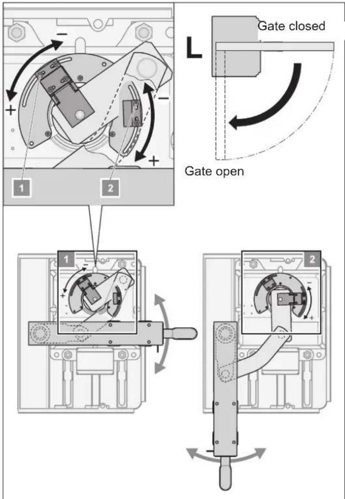
The operator is factory-set to "gate OPEN" (see illustration to the right). The end switches are factory-set for the gate end positions "gate OPEN" and gate CLOSED" to approx. 90°.
- Press key (Imp). The operator moves the gate to end position "gate OPEN".
- When end position "gate OPEN" is reached, check whether the opening angle of the gate is sufficient.
- Adjust the end switches for "gate OPEN" as required. Prior to adjusting the end switch, move the gate slightly in direction "gate CLOSED".
- Press key (Imp). The operator moves the gate to end position "gate OPEN".
- Repeat steps 1 to 4 until the desired opening angle is reached.
Adjusting end stop of right operator
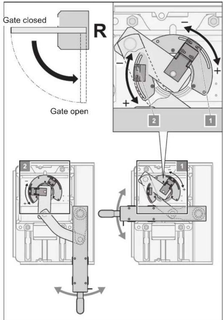
The operator is factory-set to "gate OPEN" (see illustration to the left). The end switches are factory-set for the gate end positions "gate OPEN" and gate CLOSED" to approx. 90°.
- Proceed as described under "Adjustment of end stops of left operator".
Commissioning
General instructions
- During the programming run, the "WL" LED or the connected warning lamp are flashing, irrespective of position of DIL switch 4.
- During the commissioning runs, the force necessary to properly open and close the gate, the runtime and the delay upon closing are evaluated and stored by the control system.
- If a programming run is interrupted before it is completed ("WL" LED is on during opening or closing), all previously saved values are deleted.
Preparation for standard operation
Caution!
Risk of short circuit! Prior to adjusting the DIL switch settings, disconnect control unit from power supply.
- Select 1 or 2 wing option, connect desired components and complete settings (see additional functions and connections).
- Connect control unit to power supply (AC 230V) ("Power" LED is on).
- Tighten all screws at the fittings so that the drives can easily be moved.
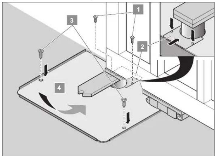
- Replace the lid (4 + 2) and tighten the screws (3 + 1) .
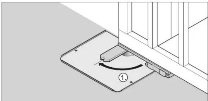
natural_image
Technical diagram of a mechanical assembly with a rotating component and base plate (no text or symbols)- Engage the gate in the gate wing fitting (push against slight resistance).
natural_image
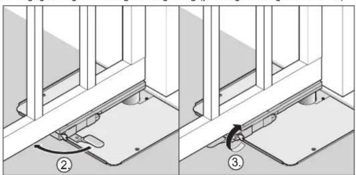
Technical diagram showing two mechanical assembly steps with numbered annotations (no text or symbols present)- Press the emergency release lever towards the gate until it engages. The gate is locked.
- Turn the key by 90° in anticlockwise direction - The emergency release lever is locked.
† The gate is now closed and locked.
Activating standard operation
"WL" LED flashes, until the values for force, runtime and closing delay have been registered and stored.
2 wing gate!
Wing 1 (M1 wing with stop) is closed first, followed by wing 2 (M2 pedestrian wing). This prevents that gates with different runtimes are closed in the wrong sequence.
- Check end switch settings. Open and close the door. If the drive switches off when an end position is reached, complete a teaching-in process.
Complete at least 2 programming runs:

Set DIL switch 8 to ON and leave it in this position.
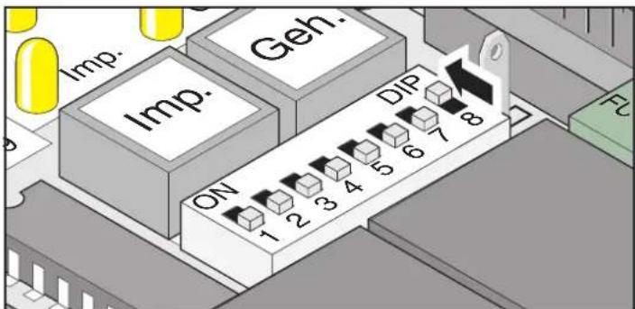
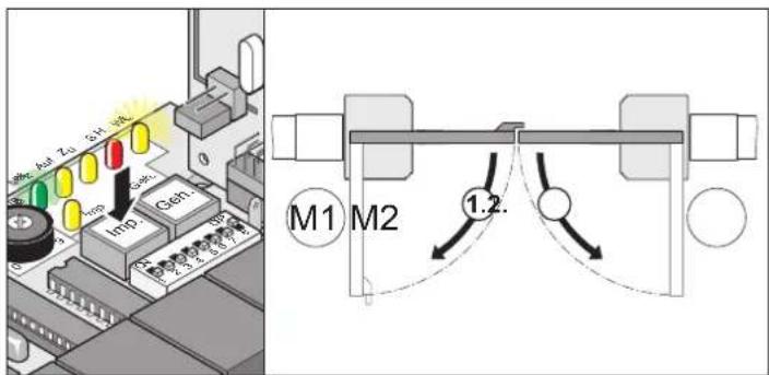
- Press key (Imp). Gate moves to end position gate "OPEN". - "Power" LED is on, "WL" LED flashes.
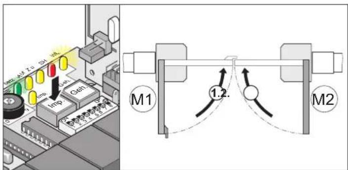
- Press key (Imp). Gate moves to end position gate "CLOSE".
- "Power" LED is on, "WL" LED flashes.
- Repeat items 1 + 2.
† When the "WL" LED stops flashing, all values have been registered and stored.
Commissioning
Upon the next command, the gates are started and stopped in soft run. The control system thereby checks the force, runtime and closing delay during every opening and closing procedure and gradually adjusts the settings each time the end position is reached.
If a programming run could not be properly completed (drives not in soft run mode, LED "WL" flashes), the control system is reset (all stored values are deleted, see control reset). Start a new programming run.
Adjusting force tolerance
After the drive system has been installed, the person responsible for the installation must complete an EU Declaration of Conformity according to Machine Directive 98/37/EU and attach a CE mark at the type plate of the drive.
This also applies in cases where the owner of the system is a private person, as well as to manually operated gates that have been upgraded with a drive. The above documents and the instructions for installation and operation must be handed over to the operator.
The force settings are relevant for the system's safety and must therefore be adjusted with due care and attention. If the force tolerance is outside the permitted range, there is a serious risk of injury and damage.
Select the lowest possible force tolerance in order to ensure that obstacles are immediately and reliably detected.
• Maximum force = programmed force + force tolerance (adjustable at potentiometer)
- If the set force is not sufficient to fully open or close the gate, increase the force tolerance by turning the potentiometer clockwise.
- Adjust value while the gate is in operation; the new values are subsequently stored upon the next opening operation of the gate.
• After the adjustment of the force tolerance is completed, check the end positions and readjust, if necessary.
Inspection of force tolerance settings
For detailed instructions, see chapter Maintenance / Regular Inspections.
Adjustment of force tolerance to programmed value. The potentiometer data is read every time the system is started.
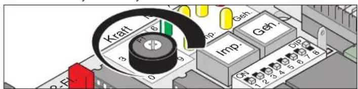
- Potentiometer at left stop (0): smallest tolerance value; potentiometer at right stop (9): greatest tolerance value
Programming of remote control
Prior to the initial programming of the hand-held transmitter, delete the radio receiver memory.
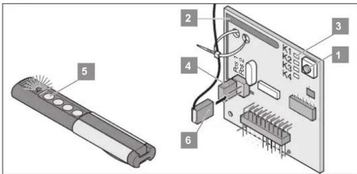
Deleting the radio receiver memory
- Press and hold the programming key (1).
- After 5 seconds, the LED begins to flash; after another 10 seconds, it is continuously on.
-
After 25 seconds, all LEDs are on.
-
Release the programming key (1).
† All LEDs are off. Deletion of the memory is completed.
Programming remote control transmitter
Gate system with 1 wing:
- Key 1 to radio channel 1
Gate system with 2 wing:
- Key 1 to radio channel 1 (both gate wings open)
-
Key 2 to radio channel 2 (only pedestrian wing opens)
-
Press the programming key (1)
1x for channel; 1 LED (K1) is on.
2x for channel 2; LED (K2) is on.
- If no radio code is transmitted within 10 seconds, the receiver switches back to normal operating mode.
- Aborting programming mode: Repeatedly press the programming key (1) until all LEDs are off.
- Press the desired remote control key (5) until LED is off - depending on chosen channel. The radio code has been transmitted from the remote control transmitter to the receiver
† LED off - programming process is completed.
Check
Press key 2. The pedestrian gate wing opens.
Press key 1. Both wings open.
Programme all other remote control devices by repeating the above steps. Each radio remote control receiver can store up to 112 different radio codes (remote control keys).
Operation and use
Safety instructions
- Never operate the drive if you suspect that it might be faulty or damaged.
- Before opening or closing the gate, ensure that no persons, especially children, animals or objects are within the opening range of the gate.
- Never use remote control device at locations where it might interfere with other important radio systems (e.g. airports, hospitals).
- Only operate the gate with the remote control when you have full view of the gate.
- Keep the remote control device out of reach of children or animals and prevent any inadvertent use.
- Use remote control device only, if the force tolerance is set to a permitted value. Select the lowest possible force tolerance to reduce the risk of injury.
Standard operation
Damage to the gate, humidity, subsidence, extreme temperature, etc. may affect the force that is required to open and close the gate.
If the force required to open or close the gate is increased within the tolerance range set at the potentiometer, the force settings are automatically adjusted accordingly. In the same way, the drive adjusts the settings, if less force is required.
Operation in summer/winter
Due to the temperature variations between summer and winter, the forces required to operate the gate might vary considerably. If the gate cannot be opened or closed, reset the control system and complete a programming run.
The temperature difference might also affect the end position of the wings. If necessary, adjust positions at the limit switch.
Intermediate stop
2 wing gate system
If the wing is opened by means of the pulse command and stopped with the stop command, before wing 1 is opened, the pedestrian gate wing can only be closed with the pedestrian gate command.
Obstacle detection:
The obstacle detection function is only working properly after the programming runs are completed and the force tolerance is set.
If the moving gate wing touches an obstacle, it is identified as such. Depending on the actual movement and DIL switch settings, the gate wing responds in different ways. The first subsequent gate movement is always away from the obstacle.
Opening and Closing Gate
• DIL switch 8 set to ON and programming run completed.
- Remote control programmed (key 1 to channel K1, key 2 to channel K2).
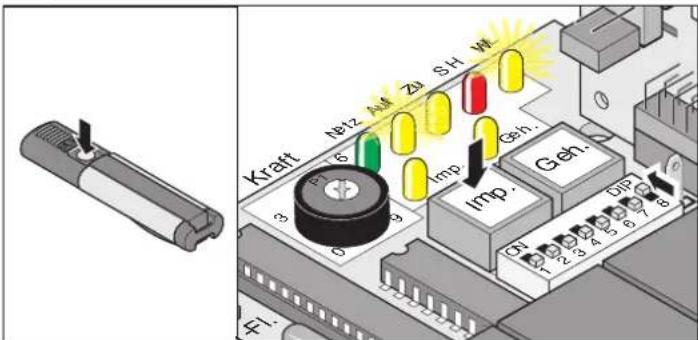
Procedure for single-wing gates
- Press key (Imp) or key 1 at remote control.
- Gate opens until end position "OPEN" is reached.
- LEDs "OPEN"+ "WL" are on.
- When end position "OPEN" is reached, the LEDs "OPEN" + "WL" are switched off.
Procedure for double-wing gates – operation of both wings
- Press key (Imp) or key 1 at remote control.
- Wing 2 (M2/pedestrian wing) opens first.
After 3 seconds, wing 1 (M1) opens - LEDs "OPEN" + "WL" are on. - When end position "OPEN" is reached, the LEDs "OPEN" + "WL" are switched off.
- Press key (Imp) or key 1 at remote control.
- Wing 1 (M1) closes first. After 5 seconds, wing 2 (M2/pedestrian wing) closes – LEDs "CLOSE" + "WL" are on.
- When end position "CLOSE" is reached, the LEDs "CLOSE" + "WL" are switched off.
Procedure for double-wing gates – operation of pedestrian gate only
- Press key (Geh) or key 2 at remote control.
- Wing opens until end position "OPEN" is reached – LEDs "OPEN" + "WL" are on.
- When end position "OPEN" is reached, the LEDs "OPEN" + "WL" are switched off.
- Press key (Geh) or key 2 at remote control.
- Gate closes until end position "CLOSE" is reached – LEDs "CLOSE" + "WL" are on.
- When end position "CLOSE" is reached, the LEDs "CLOSE" + "WL" are switched off.
Resetting control
When the control system is reset, all programmed values (e.g. force settings: drive force required to open/close the gate, delay settings) are deleted. Under certain circumstances, it might be necessary to delete all stored values and reprogramme the system.
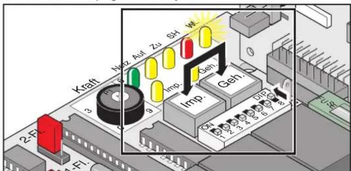
- Press keys (Imp. + Geh) and hold until LED "WL" begins to flash.
- LED "WL" is off - all data is deleted. Release keys.
- LED "WL" flashes.
- Complete programming run, see chapter "Activating Standard Operation".
Operation and use
Emergency release in the event of a power Failure
This procedure should only be applied if the control system is not powered and is secured against inadvertent activation.
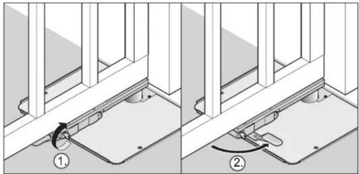
In the event of a power failure, the gate can be manually opened or closed, irrespective of its initial position. The gate can be locked and released from both sides.
Releasing operator
natural_image
Technical diagram showing two mechanical assembly steps with numbered annotations (1 and 2), no readable text or symbols present.- Turn the key by 90° in clockwise direction – the emergency release lever is released.
- Pull the emergency release lever way from the gate (approx. 90°). The gate is released.
natural_image
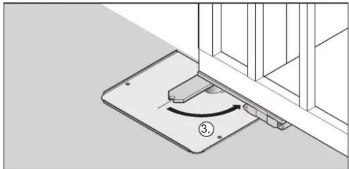
Technical diagram showing a mechanical assembly with a rotating component and a numbered label (3), no readable text or symbols present.- Disengage the gate from the gate wing fitting (push against slight resistance).
Locking operator
natural_image
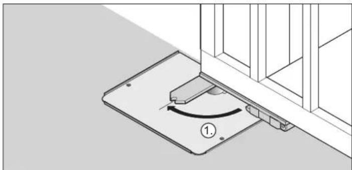
Technical line drawing of a mechanical assembly with a curved component and base plate (no text or symbols)- Engage the gate in the gate wing fitting (push against slight resistance).
natural_image
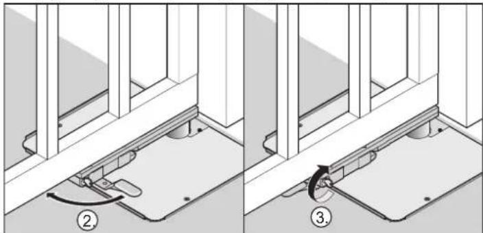
Technical diagram showing two mechanical assembly steps with numbered annotations (no text or symbols present)- Press the emergency release lever towards the gate until it engages. The gate is locked.
3 Turn the key by 90° in anticlockwise direction. The emergency release lever is locked.
Opening foundation box
The foundation box may only be opened after the control system has been disconnected from the power supply and secured against inadvertent activation.
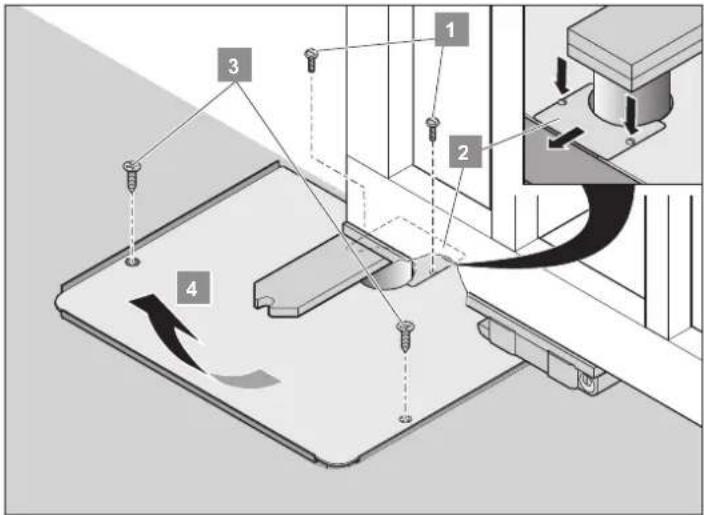
- Gate opens until end position "gate OPEN" is reached.
- Disconnect the control system from the power supply and secure it against inadvertent activation.
- Remove the screws (1 + 3). Remove the lid (2 + 4).
† Open the foundation box.
Radio receiver
Homelink compatible!
If your vehicle is equipped with a Homelink system (version 7), you can reach our drive/radio receiver at 868.6 MHz. With holder Homelink systems, you must use a different frequency (40.685 or 434.42 MHz). For more information, please visit: "http://www.eurohomelink.com"
Safety instructions
- The operator of this radio-controlled equipment is not in any way protected against interference from other telecommunications systems and facilities (e.g. other radio-controlled equipment that is licensed to operate at the same frequency range).
• In the event of poor reception, replace the battery of the remote control.
Operation and use
Display and keys
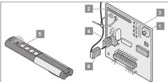
Programming key
Internal aerial
LEDs: indicate the selected channel.
K1 = radio channel 1 -> same function as Imp key
K2 = radio channel 2 -> same function as pedestrian gate key
! K3 = radio channel 3 -> no function assigned
! K4 = radio channel 4 -> no function assigned
Connection for external aerial (6)
If the internal aerial does not have the necessary reach, connect an
external aerial to the device. For details, see accessories.
Remote control transmission key
External aerial
Programming of remote control device

Prior to teaching in the hand transmitter, clear the radio receiver memory.
- Press the programming key (1)
1x for channel 1; LED (K1) is on.
2x for channel 2; LED (K2) is on. - If no radio code is transmitted within 10 seconds, the receiver switches back to normal operating mode.
- Aborting programming mode: Repeatedly press the programming key (1) until all LEDs are off.
- Press the desired remote control key (5) until LED is off - depending on chosen channel.
The radio code has been transmitted from the remote control transmitter to the receiver.
† LED off - programming process is completed.
Programme all other remote control devices by repeating the above steps. Each radio remote control receiver can store up to 112 different radio codes (remote control keys).
Disabling remote control key at receiver
If, for instance, a user of a parking facility is moving house and wishes to keep his remote control device, all radio codes of this device must be disabled at the receiver.

For reasons of safety, we recommend to disable every single key and possible key combination!
- Press programming key (1) and hold for 5 seconds until one of the LEDs is flashing.
- Release programming key (1) – the radio receiver is now in delete mode.
- Press the remote control key whose radio code is to be deleted from the radio receiver memory.
† LED is off - the deletion process is completed.
Deleting all radio codes of a channel
- Push the "Learn" button (1)
1x for channel 1, LED (3.1) lights up
2x for channel 2, LED (3.2) lights up - LED is on, depending on which channel has been selected.
After 5 seconds, the LED starts to flash and then after an additional
10 seconds is continuously illuminated - Release the 'Learn' button (1) - deletion process is completed.
Deleting the radio receiver's memory
If a remote control transmitter is lost, we recommend deleting all data in the radio receiver memory for safety reasons.
All remote control devices must subsequently be programmed again.
- Press and hold the programming key (1).
- After 5 seconds, the LED begins to flash; after another 10 seconds, it is continuously on.
- After 25 seconds, all LEDs are on.
- Release the programming key (1).
† All LEDs are off – Deletion of the memory is completed.
Connecting an external aerial
- The aerial cable should not place any mechanical stress on the radio remote control receiver, attach a strain relief device.
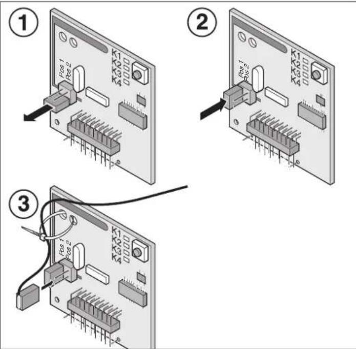
Troubleshooting
All LEDs are flashing:
Attempt to save more than 112 radio codes (remote control keys) in the radio receiver. If you wish to save additional radio codes over and above the already stored 112 codes (remote control keys), you must first delete some of the stored (unused) codes.
The LED is on; the device is in programming mode:
- Radio receiver is awaiting a code signal from a remote control transmitter.
- Radio receiver receives a signal from a remote control transmitter.
Additional functions and connections
Jumpers
Selection of gate system (single-wing or double-wing)
i After changing the jumper settings, reset the control system and complete a new programming run.
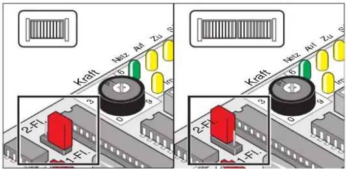
Label Function
2-wing / 1-wing Jumper at upper pins = double-wing
Jumper at lower pins = single-wing
Jumper not set = single-wing
Potentiometer for force tolerance settings
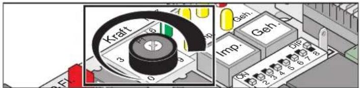
Adjustment of force tolerance to programmed value. The potentiometer data is read every time the system is started.
If the potentiometer is set to the left stop (0), the force tolerance is minimal, if set to the right stop (9), the force tolerance is set to the highest value.
Control panel keys
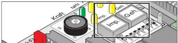
Label Function
Imp. Pulse key: opens both gate wings
If the Imp key is pressed while a pedestrian gate wing is in motion, the wing is stopped. If the pedes trian wing is fully opened, wing 1 can be opened by pressing the Imp key.
Sequence:
open - stop - close - stop - open ...
Geh. Pedestrian gate key: Open only the pedestrian gate
In a double-wing gate, this key opens only gate wing 2. In gates where the stop bar is on the outside, wing 2 always opens before wing 1.
Sequence:
open - stop - close - stop - open ...
Key (Geh) is only enabled, if wing 1 is fully closed.
Reset of control:
To reset the control, press both keys together for minimum 5 seconds until LED (WL) is switched off.
LEDs
The LEDs indicate the control system status.
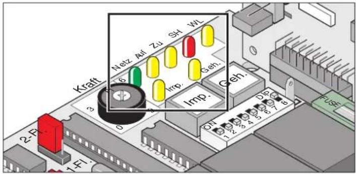
Label Colour Status
| Power green OFF = no powerON = power in low-voltage range (24 V) of the control | ||
| If the mains fuse is blown, this LED is off; terminals 1, 2, 19 or 21 might however be powered with mains voltage (AC 230 V). | ||
| OPEN | yellow | OFF = idleON = gate is opening |
| CLOSE | yellow | OFF = idleON = gate is closing |
| SH | red | OFF = idleON = signal at safety input(light barrier triggered) |
| WL | yellow | OFF = idle, with programmed force valuesflashing = test mode, where DIL switch 8 is set to OFF.- During programming run, where DIL switch 8 is set to ON.- The gate is opened and closed, where-by the programmed force values are applied and DIL switch 4 is set to ON.ON = gate is opening or closing with the programmed force values, and DIL switch 4 is set to OFF. |
| Imp. | yellow | OFF = idleON = pulse key or radio channel 1 activated. |
| Geh | yellow | OFF = idleON = pedestrian gate key or radio channel 2 activated. |
Additional functions and connections
DIL switch
Factory settings: OFF
Prior to adjusting the DIL switch settings, disconnect the control unit from the power supply.
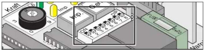
Switch Position OFF Position ON
| 1 | No response to signal at the safety input upon opening of gate. | Gate is stopped, when the safety input is triggered while the gate is opening. |
| 2 | Gate movement reversed, when safety input is triggered while the gate is closing. | Gate is stopped, when the safety input is triggered while the gate is closing. |
| 3 | Switch 2 OFF: reversion | Switch 2 OFF: gate is fully opened |
| 4 | Warning lamp is on | Warning lamp flashes |
| 5 | Early warning OFF | Early warning period approx. 3 seconds. Lamp is on or flashes, before the gate is started, depending on position of switch 4. |
| 6 * | Manual mode | Automatic close mode: Gate is automatically closed after 60 seconds. |
| 7 * | No function assigned | Switch 6 ON, gate closes automatically 5 seconds afterthe light barrier has been triggered |
| 8 | Test mode:Drive can be operated while no force values are programmed.Use test mode to adjust end position settings. | Standard mode:- After switching from OFF to ON; the force values, run times, and delays for closing/opening are programmed in the course of programming runs.- The gate opens or closes. |
* See TorMinal manual
Operate gate only within full view of the gate's operating range.
After programming, leave DIL switch 8 in position ON.
Automatic close mode
For operation with automatic close mode, comply with EN 12453 (e.g. installation of light barrier 1).
The gate closes automatically after the time for GATE OPEN set at the potentiometer has lapsed. The gate can only be opened by means of a command issued via a push-button or manual remote control. When the gate is opening, no command issued can stop it from doing so. When it is closing automatically and a further command is given, the gate opens fully. If a command is issued during the GATE OPEN period, this period is restarted.
The GATE OPEN time can be adjusted at DIL switch 6:
- Time (adjustable in TorMinal): 5 to 255 seconds
Behaviour of the drive system when a signal is received at the safety input
While gate is closing:
drive behaves according to the settings of DIL switch 2.
While gate is opening:
drive behaves according to the settings of DIL switch 1.
Automatic close mode, option 1
Automatic closing is activated as soon as the end position gate OPEN is reached; at this moment, the GATE CLOSE time set at the potentiometer is started.
If a command is issued during the GATE CLOSE period, this period is restarted.
Settings:
- set potentiometer to the desired time (5 to 255 seconds)
- DIL switch 7 OFF
- DIL switch 8 ON
- Other DIL switches set as required
Automatic close mode + light barrier, option 2
This option allows for the manual interruption of the automatic closing motion.
Similar to the option described above; the gate is however automatically closed 5 seconds after the light barrier has been triggered.
Settings:
- set potentiometer to the desired time (5 to 255 seconds)
- DIL switch 7 ON
- DIL switch 8 ON
- Other DIL switches set as required
Slot for radio receiver
The radio receiver is inserted here (factory-installed).
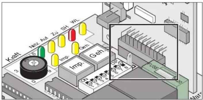
Fuses
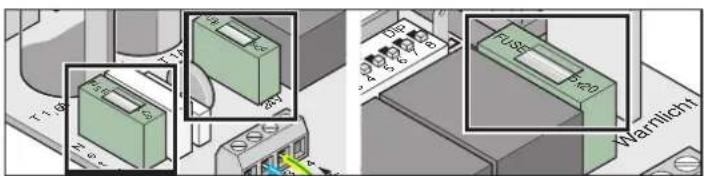
Label Capacity Description
Mains 1,6 A, slow Power supply line AC 230 V
24 V 1 A, slow Power output DC 24 V
Terminals 9 + 10
Warning light 1 A, slow Warning light output DC 24 V
Terminals 11 + 12
Additional functions and connections
Potential-free relay contact
Admissible cable diameters for all terminals: 1 mm ^2 - 2.5 mm ^2
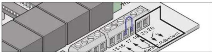
25 + 26 Special funct. Connection for electric lock, etc.
max. 8 A, DC 24 V at ohmic load
Connecting safety devices
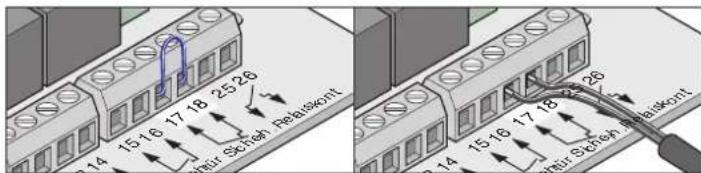
For operation with automatic close mode, comply with EN 12453 (e.g. installation of light barrier).
Factory settings: Bridge between terminals 17 + 18.
Terminal Label Function
| 17 + 18 Sicherh. Connection for safety devices, e.g. |
| - Light barrier |
| - Contact strip |
| If the connected safety device is not triggered, the contact must be closed. |
| If the contact is not used, mount a bridge between the terminals (factory settings). |
Use contact only for potential-free normally closed contacts. External voltage may damage the control system.
Connect keys
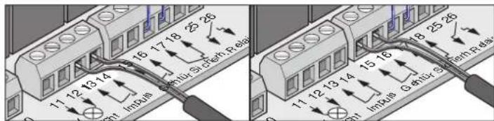
Terminal Label Function
| 13 + 14 Pulse Connection for pulse key used to operate one or both gate wings. | |
| 15 + 16 Pedestrian wing | Connection for pulse key used to operate one gate wing. |
Use connections only for potential-free NO contacts. External voltage can damage or even destroy the control system.
A 2-contact key is only required for double-wing gates, and if the pedestrian gate function is to be used.
In single-wing gates, the pulse and the pedestrian gate key are assigned identical functions.
Connection Key 1 Contact
single-wing gate system Key to terminals 13 + 14 or 15 + 16
double-wing gate system Key to terminals 13 + 14
Connection Key 2 Contact
Pedestrian gate terminals 15 + 16
Both wings terminals 13 + 14
Connecting warning lamp
Available as optional accessories.
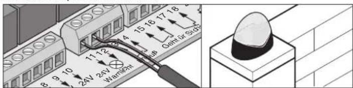
For function settings, see DIL switches 4 + 5
Terminal Label Function
11 + 12 24 V Warn. lamp Connection for 24-V-warning lamp, fused with 1A at max. 20W.
Rectified, not stabilised transformer voltage, fluctuating between 22V and 27V at full load.
Connecting external device
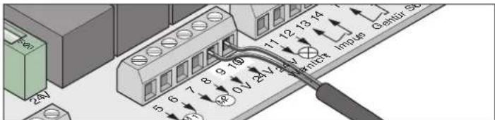
Terminal Label Function
| 9 | 0 V | |
| 10 | 24 V | 24V output, fused with 1A max. 20W |
Rectified, not stabilised transformer voltage, fluctuating between 22V and 27V at full load.
Connecting drives
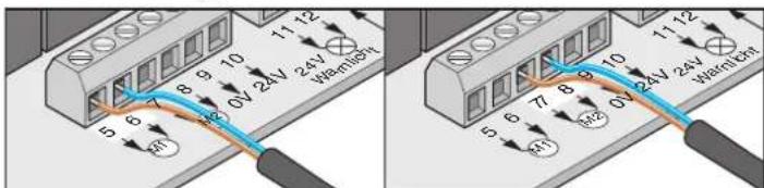
Terminal Label Function
| 5 + 6 | M1 single-wing gate: no function assigneddouble-wing gate: connection for motor-1The motor must be mounted on the wing that opens as the second wing, or that is equipped with a stop bar at the outside.Terminal 5: Motor cable, brownTerminal 6: Motor cable, blue |
| 7 + 8 | M2 single-wing gate: connection for motordouble-wing gate: connection for motor-2The motor must be mounted on the wing that opens as the first wing, or that is not equipped with a stop bar at the outside.Terminal 7 Motor cable, brownTerminal 8: Motor cable, blue |
Additional functions and connections
Connecting to power supply (230 V)
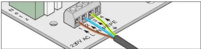
Terminal Label Function
| 1 | L | Power conductor AC 230 V |
| 2 | N | Neutral conductor |
| 3 + 4 PE Earth conductor | ||
The connection to the power supply must be carried out by a qualified electrician.
Connection of transformer
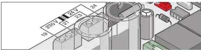
Terminal Label Function
| 19 + 21 AC 230 V Power supply (primary winding), brown |
| 23 + 24 AC 24 V 24V output (secondary winding), power supply line to control unit, mauve |
Accessories
Safety instructions
Caution!
Prior to any work on the gate or drive, disconnect control unit from the power supply and secure it against inadvertent reconnection or actuation.
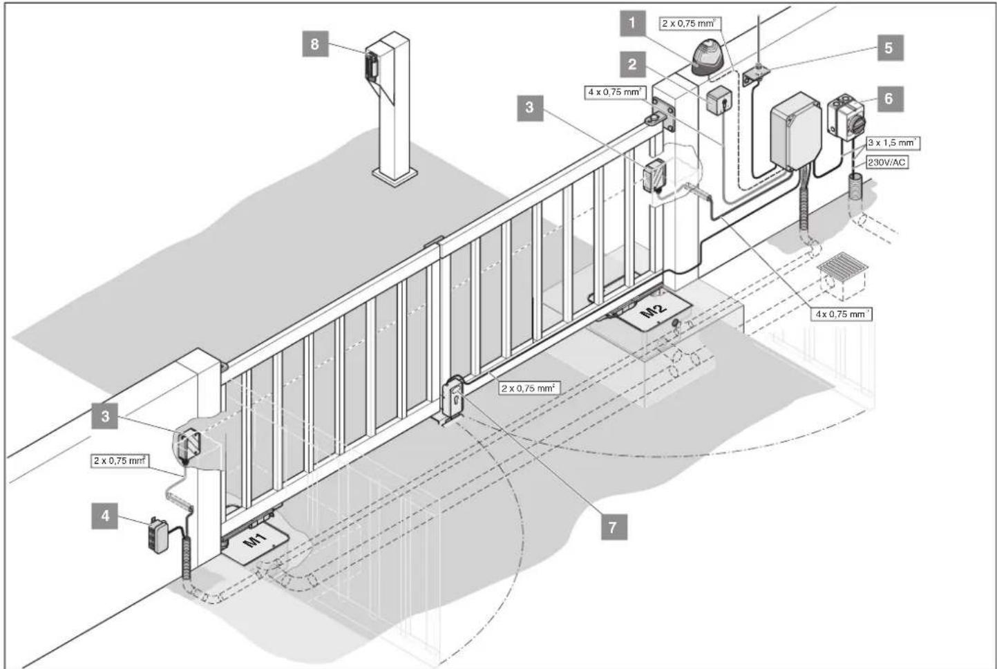
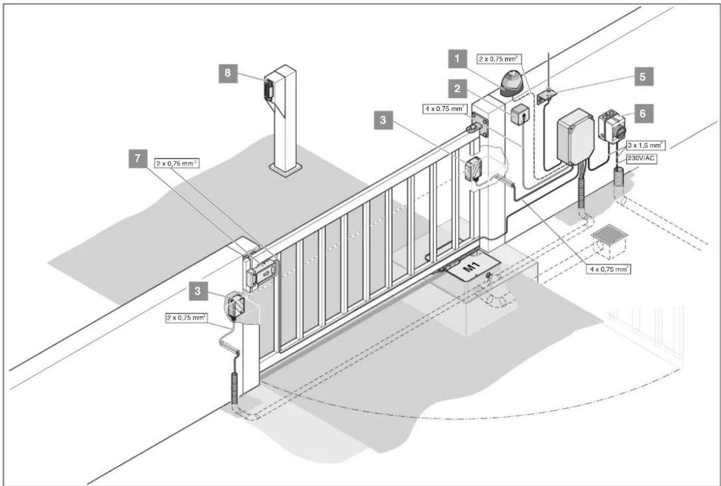
1. Warning lamp
2. Key switch
Position the key switch box in such a way that the operator can see the gate, while he/she is not inside the operating area of the gate.
- Never lead the key switch cable along the power line, as this could lead to interference in the control system.
- Use a separate conduit for the key switch line.
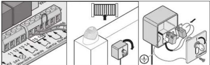
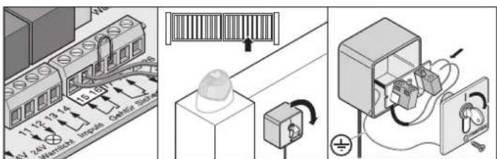
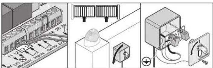
- Install key switch box at a suitable location where it can be easily accessed.
3. Light barrier
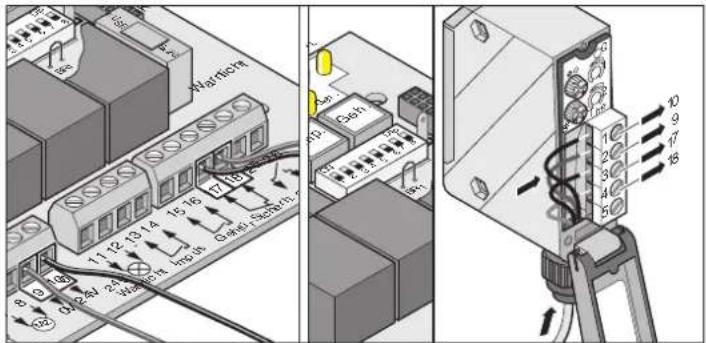
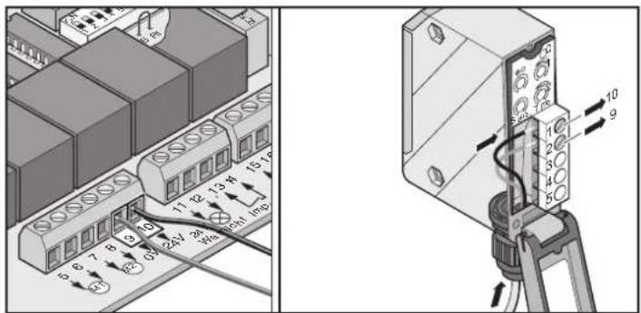
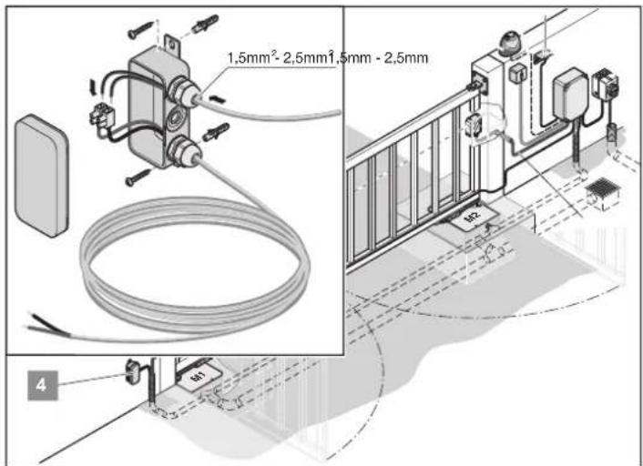
4. Connecting cables
- Secure distribution box with screws at the provided eyelets.
Installation
Only connect cables that have the same colour, i.e.:
- blue to blue
- brown to brown
Secure screws tightly to prevent moisture from penetrating the distribution box. After installation, connect distribution box to power supply.
Wiring diagram:
Accessories
5. External aerial
- If the built-in aerial is not sufficient for the proper operation of the gate, you have the option to connect an external aerial to the system.
- Ensure that the aerial cable is laid in such a way that there is no physical impact to the radio transmitter. Install tension protection, if necessary.
- Consult the operator/owner of the system in order to find a suitable location for the external aerial.
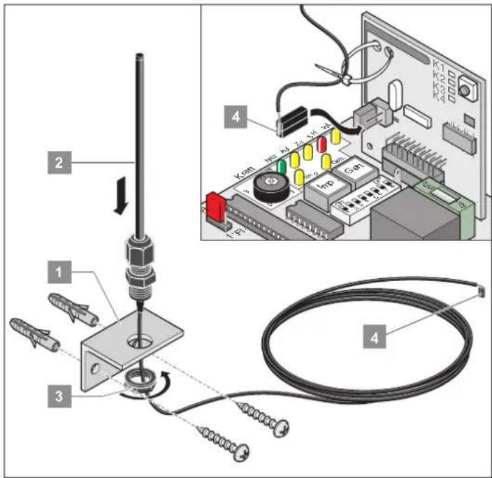
- Connect external aerial to the respective adapter.
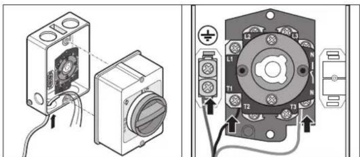
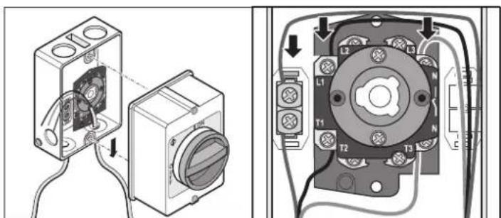
6. Main switch
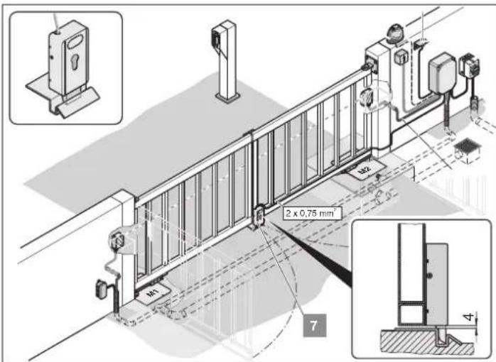
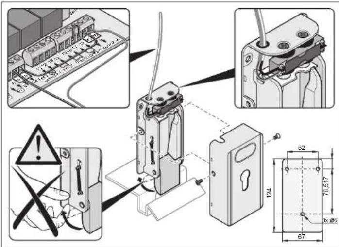
7. 24 V electric lock
Installation:
- Reset the control system.
- After completion of the installation adjust end position gate "CLOSE".
- Mount the lock horizontally, as it might otherwise be jammed when the gate is operated.
• Distance between lock and closing plate: min. 4 mm, max. 6 mm.
Wiring diagram of 24 V electric lock
This wiring diagram is only valid for 24 V electric locks. 12 V electric locks may only be connected after consultation with the manufacturer.
Maintenance
Safety instructions
Never clean drive system or control unit with a water hose or power washer.
- Never clean the drive with alkaline or acidic solutions.
- Carefully remove dirt from drive system and clean push rod from time to time with a dry cloth.
- If necessary, clean and/or dry.
- Regularly inspect all screws at the fittings and retighten, if necessary.
- Inspect the cover of control unit and readjust, if necessary, to ensure that it is watertight.
Regular inspections
- Check safety devices regularly, at least once a year, to ensure proper functioning (e.g. BHR 232/2003, only applicable in Germany).
- Safety devices that are sensitive to pressure (e.g. safety switch unit) should be checked every 4 weeks to ensure proper functioning, see EN 60335-2-95.
Service and warranty
The warranty granted complies with statutory requirements. In the event of a repair that is covered by warranty, please contact your dealer/specialist stockist. Warranty entitlements only apply to the country in which the product has been purchased. Batteries, fuses and light bulbs are not covered by warranty. Replaced parts remain the property of the service agent. If you require after-sales service, spare parts or accessories, please contact your dealer/specialist stockist. We have made every effort to ensure that these instructions are as clear and concise as possible. However, if you have any queries or wish to comment on this document, please contact us with your suggestions:
Fax.: 0049 / 7021 / 8001-403
email: doku@sommer.eu
Disassembly
Observe safety instructions!
To dismantle the unit, complete the respective steps described in chapter "Installation" in reverse order. There is of course no need to adjust settings.
| Test | Behaviour yes/no | Possible cause Remedy | ||
| Force cut-offWhile the wing isclosing, try to stop it by hand. Do not try to hold the wing. | Does gate stop and move in opposite direction after it has been halted? | yes | ·Force cut-off works properly · | Do not change settings. |
| no | ·Potentiometer at right stop. Force tolerance set too high. ·Control system defective | ·Set force tolerance to lower value by turning the potentiometer in anticlockwise direction until the test is successful. Prior to test, open and close the gate twice observing its operation. ·Shut down the gate and secure against switching on. Contact customer service! | ||
| Emergency release systemProceed as described in section “Emergency Release”. | It must be possible to open/close the gate by hand without special effort.Can the motor be removed from the shaft? | yes | ·Everything OK! | |
| no | ·Gate fittings rusty ·Emergency release damaged | ·Lubricate gate fittings ·Repair emergency release, call customer service. | ||
| Safety contact unit (optional)Open/close gate and interrupt motion by triggering the safety contact strip. | Gate behaviour according to settings of DIL switches 1, 2 and 3. | yes | ·Everything OK! | |
| no | ·Cable defective, terminal screw loose ·DIL switch settings changed ·Contact strip defective | ·Inspect wiring, retighten terminal screws ·Check DIL switch settings and adjust ·Shut down gate system and secure against inadvertent switching on. Contact customer service! | ||
| Light barrier (optional)Open/close gate and interrupt motion by triggering the light barrier. | Gate behaviour according to settings of DIL switches 1, 2 and 3. Is the LED “SH” on? | yes | ·Everything OK! | |
| no | ·Cable defective, terminal screw loose ·DIL switch settings changed ·Light barrier dirty ·Light barrier defective | ·Inspect wiring, retighten terminal screws ·Check DIL switch settings and adjust ·Clean light barrier ·Shut down gate system and secure against inadvertent switching on. Contact customer service! | ||
Troubleshooting
Tips for troubleshooting
Should you be unable to identify and eliminate a fault using this table, please take the following steps:
- Carry out a reset of the control system (deletion of set force values).
- Disconnect any accessories (e.g. light barrier) connected to your system.
- Reset all DIL switches to the default settings.
- Reset potentiometer to the default settings.
- If settings have been changed with TorMinal, reset the control system with the TorMinal software.
| Fault Check yes/no Possible cause Remedy | ||||
| Gate cannot be opened or closed with the switch or the remote control. | Is “Power” LED on? | no | No mains powerMains fuse blown | Check power line and reconnect, if necessary.Check fuse and replace, if necessary. |
| yes | Gate jammedMotor makes a sound but does not moveDrive disengagedCable insulation too long, preventing contactGate frozen to ground/postsGate obstructed by snowCable disconnected from motor board | A gate wing has been pushed down or has warped due to high temperature differences.Shut down unit. Possible motor and/or control system failure. Contact customer service.Engage drive.Disconnect cable, remove insulation and reconnect again.Remove ice and snow from gate and hinges.Remove snow.Reconnect cable to motor board | ||
| Is LED at the remote control device on? | no | Battery emptyBattery incorrectly insertedRemote control defective | Replace batteryInsert battery correctlyReplace remote control device | |
| yes | Remote control battery nearly empty; resulting in limited radio rangeRadio receiver defectiveRemote control not programmedPoor receptionWrong frequency | Replace batteryReplace radio receiverProgramme remote control deviceInstall external aerial, see section “Accessories”Check frequency; remote control and radio receiver must be set to the same frequency. | ||
| Is at least one LED at the receiver on when a remote control key is pressed? | no | Radio receiver not properly mountedRadio receiver not powered, or defectiveRemote control not programmedBattery of remote control emptyBattery incorrectly insertedRemote control defective | Check and readjust radio receiverReplace radio receiverProgramme remote control deviceReplace batteryInsert battery correctlyReplace remote control device | |
| Are LEDs “Power” + “OPEN/CLOSE” on? | yes | Pulser defective; disconnect all pulsers | Permanent signal | |
| Are LEDs “Power” + “SH” on? | yes | Remove object triggering the barrier | Light barrier triggered | |
| Disruption occurs only from time to time or temporarily | yes | Powerful radio transmitters (pager systems) of hospitals or industrial plants might interfere with your gate system. | Change radio frequency.Contact telecommunication authority. | |
Troubleshooting
| Fault Check yes/no Possible cause Remedy | ||||
| Gate cannot be opened/closed with a key switch. | LEDs "Power" + "Imp./Geh" on? | no | Cable connections looseKey switch defective, possible water damage.Cable defective | Retighten terminalsReplace key switchReplace cable |
| yes | Pulser (key switch, remote control) defective | Check pulser and replace, if defective. | ||
| Gate is stopped or continues in reverse motion. | Obstacle in operating range? | no | Hinges too stiffPost has movedLimit switch settings incorrect | Lubricate hingesContact specialistReadjust limit switch |
| yes | Force cut-off triggered · Remove obstacle | |||
| Is gate wing hopping at start? | yes | Wing not stable · Reinforce wing | ||
| Is there strong wind? | yes | Wind pressure too high | Simply open and close gate again | |
| Gate does not fully open or close. | Does gate stop before it has reach its end position? | no | Wing hinge incorrectly mounted | Change fittings at wing |
| yes | Limit switch settings incorrect | Readjust limit switch | ||
| Incorrect closing sequence | Drive wires incorrectly | connected at terminals | Read the instructions and reconnect drives to the control system | |
| Drive cannot be properly programmed | DIL switch 8 is in position OFFEnd switch incorrectly set | Set DIP switch 8 to ONAdjust end switch | ||
| Gate is not stopped by an obstacle | Gate is completing a programming runForce tolerance set too high | After the programming is completed, the force cut-off is operationalReduce force tolerance, see "Adjusting force tolerance". | ||
| Pedestrian wing cannot be opened with remote control device | Remote control key not programmed | Programme key, see "Programming remote control transmitter". | ||
| Drive cannot be started | Is LED "SH" flashing rapidly? | yes | Position of jumper with programmed force values has been changed | 1. Reset jumper to previous position2. Reset control system3. Position jumper as desired4. Complete programming runs |
Wiring diagram
- jive 200 E
- Contents
- General information....2
- Installation 4
- Commissioning 9
- Operation and use....11
- Additional functions and connections.... 14
- Accessories 18
- Maintenance....20
- Disassembly....20
- Troubleshooting....21
- Spare parts list / Glossary 23
- Wiring diagram....25
- EU declaration of conformity
- Safety instructions
- General safety instructions
- Operation
- Radio remote control
- Rating plate
- Normal use
- General information
- Permitted gate wing dimensions
- Technical data
- Dimensions
- Functions
- Locking of gate
- An electric lock can be mounted for additional safety.
- Remote control
- Safety devices
- EU manufacturer's declaration
- Caution!
- Tips for installation
- Installation
- Supplied components
- Complete installation kit 1 wing 2 wing
- Location of installation
- Installation of gate wing fittings
- Installation of control unit
- Connecting to power supply (230V)
- Connecting the operator to the control unit
- Checking direction of movement
- Adjusting end stops
- Commissioning
- General instructions
- Preparation for standard operation
- Activating standard operation
- Complete at least 2 programming runs:
- Adjusting force tolerance
- Inspection of force tolerance settings
- Programming of remote control
- Deleting the radio receiver memory
- Programming remote control transmitter
- Gate system with 1 wing:
- Gate system with 2 wing:
- Check
- Operation and use
- Standard operation
- Operation in summer/winter
- Intermediate stop
- wing gate system
- Obstacle detection:
- Opening and Closing Gate
- Procedure for single-wing gates
- Procedure for double-wing gates – operation of both wings
- Procedure for double-wing gates – operation of pedestrian gate only
- Resetting control
- Emergency release in the event of a power Failure
- Opening foundation box
- Radio receiver
- Display and keys
- Programming of remote control device
- Disabling remote control key at receiver
- Deleting all radio codes of a channel
- Deleting the radio receiver's memory
- Connecting an external aerial
- Troubleshooting
- Additional functions and connections
- Jumpers
- Potentiometer for force tolerance settings
- Control panel keys
- LEDs
- DIL switch
- Automatic close mode
- Automatic close mode, option 1
- Settings:
- Automatic close mode + light barrier, option 2
- Slot for radio receiver
- Fuses
- Label Capacity Description
- Potential-free relay contact
- Connecting safety devices
- Connect keys
- Connecting warning lamp
- Connecting external device
- Connecting drives
- Connecting to power supply (230 V)
- Connection of transformer
- Accessories
- Warning lamp
- Key switch
- Light barrier
- Connecting cables
- External aerial
- Main switch
- 24 V electric lock
- Installation:
- Wiring diagram of 24 V electric lock
- Maintenance
- Regular inspections
- Service and warranty
- Disassembly
- Tips for troubleshooting
- Wiring diagram
Brand : Sommer
Model : Jive 200 E
Category : Garage door opener