Twist AM - Garage door opener Sommer - Free user manual and instructions
Find the device manual for free Twist AM Sommer in PDF.


| Product Type | Electromechanical swing gate operator for 1- or 2-leaf gates |
| Power Supply | AC 220-240 V, 50-60 Hz |
| Maximum Torque per Leaf | 120 Nm |
| Rated Torque per Leaf | 40 Nm |
| Rated Power Consumption per Leaf | 85 W |
| Rated Current Consumption per Leaf | 0.5 A |
| Power Saving Mode Consumption | < 0.5 W |
| Maximum Gate Weight per Leaf | 250 kg |
| Maximum Leaf Length | 2,500 mm |
| Gate Inclination | 0% (not suitable for inclined gates) |
| Duty Cycle | S3 = 15% |
| Operating Temperature Range | -25 °C to +65 °C |
| IP Protection Class | IP44 |
| Insulation Class | II (double insulation) |
| Noise Level | < 50 dB(A) |
| Radio Receiver Memory | 40 positions |
| Angular Velocity | Approx. 11°/s |
| Safety Features | Obstacle detection with reversal, emergency release, photocell and safety strip compatibility, external EMERGENCY STOP |
| Functions | Remote control (SOMloq2), automatic closing, power-saving mode, programmable end positions and forces, jog mode |
| Maintenance | Every 3 months: check operation, clean photocells, inspect for damage; annual professional service recommended |
| Spare Parts and Accessories | Available from SOMMER: handheld transmitters, photocells, warning light, accumulator, electric lock, memory extension (Memo) |
| Warranty | Statutory warranty through qualified dealer; warranty excludes consumables and wear parts |
| Dimensions (Master/Slave Operator) | 261 x 278 x 294 mm (approx.) |
Frequently Asked Questions - Twist AM Sommer
User questions about Twist AM Sommer
0 question about this device. Answer the ones you know or ask your own.
Ask a new question about this device
Download the instructions for your Garage door opener in PDF format for free! Find your manual Twist AM - Sommer and take your electronic device back in hand. On this page are published all the documents necessary for the use of your device. Twist AM by Sommer.
USER MANUAL Twist AM Sommer
natural_image
Technical line drawing of a mechanical device with a curved top and metal bracket (no text or symbols)EN TRANSLATION OF THE ORIGINAL INSTALLATION AND OPERATING MANUAL
Swing gate operator
twist AM
Download the current manual:






Dear customer,
This product has been developed and manufactured under high standards of quality and with reference to ISO 9001.
Our passion for the product is just as important to us as the needs and requirements of our customers. We place particular emphasis on the safety and reliability of our products.
Read this installation and operating manual carefully and follow all instructions. This will ensure that you can install and operate the product safely and optimally.
If you have any questions, please contact your specialist retailer or installer.
All our products are intended for use by persons of all genders, even where this is not specifically stated.
Warranty
The warranty complies with statutory requirements. The contact person for warranties is the qualified dealer. The warranty is only valid in the country in which the operator was purchased.
There is no warranty for consumables such as batteries, accumulators and safety products as well as light bulbs.
This also applies for wear parts.
The operator is only designed for a limited frequency of use. More frequent use leads to increased wear.
Contact data
If you require after-sales service, spare parts or accessories, please contact your qualified specialist retailer or installer.
Feedback on this Installation and Operating Manual
We have tried to make the Installation and Operating Manual as easy as possible to follow.
If you have any suggestions as to how we could improve it or if you think more information is needed, please send your suggestions to us:

If you require service, please contact us on our service hotline (fee required) or see our web site:
+49 (0) 900 1800-150 (€ 0.14/minute from land line telephones in Germany, mobile prices may vary)
Copyright and proprietary rights
The manufacturer retains the copyright for this Installation and Operating manual. No part of this Installation and Operating Manual may be reproduced in any form or processed, copied, or distributed using electronic systems without the written permission of SOMMER Antriebs- und Funktechnik GmbH. Violations of the specifications above will lead to claims for damages. All brands mentioned in this Installation and Operating Manual are the property of their respective manufacturer and hereby recognised as such.
1. About this Installation and Operating Manual 4
1.1 Storage and circulation of the Installation and Operating Manual 4
1.2 Important for translations 4
1.3 Description of the product type 4
1.4 Target groups of the Installation and Operating Manual 4
1.5 Explanation of symbols and notes 4
1.6 Special warning symbols and mandatory signs 5
1.7 Information regarding the depiction of.text 5
1.8 Intended use of the operator 6
1.9 Improper use of the operator 6
1.10 Qualifications of personnel 6
1.11 Information for the user 7
2. General safety instructions 8
2.1 Basic safety instructions for operation 8
2.2 Additional safety information for the radio remote control 9
2.3 Notes and information on operation and remote control 9
2.4 Simplified Declaration of Conformity for radio systems 9
3. Description of function and product 10
3.1 The operator and its mode of operation 10
3.2 Safety equipment 11
3.3 Product designation 11
3.4 Explanation of tool symbols 11
3.5 Scope of delivery 12
3.6 Technical data 14
3.7 Overview of gate operator 15
3.8 Definitions 16
3.9 Dimensions and weights 16
4. Tools and protective equipment 17
4.1 Required tools and personal protective equipment 17
5. Declaration of Installation 17
6. Installation 18
6.1 Important notes and information 18
6.2 Preparing for installation 19
6.3 Pre-assembling the operator arm 21
6.4 Installing the operator arm 22
6.5 Installing the post fitting 22
6.6 Installing the operator 23
6.7 Installing the gate arm 23
6.8 Checking for freedom of movement 23
6.9 Adjusting the blocking elements 24
6.10 Installing the gate leaf fitting 25
6.11 Installing accessories 25
7. Electrical connection and special functions 26
7.1 Testing the provisional connection 26
7.2 Disconnect the control unit from the mains voltage 26
7.3 Overview of control unit 27
7.4 Connection options on the master and slave gate operator 28
7.5 Overview of the LEDs 29
7.6 Basic configuration 30
7.7 Preparing connections for the various functions 30
7.8 Connecting slave gate operator 30
7.9 Connecting the warning light (WL) 31
7.10 Connecting photocells 31
7.11 Connecting safety contact strip 32
7.12 Connecting an external EMERGENCY STOP 32
7.13 Connecting an electric lock (ELock) 32
7.14 Connecting control elements 33
7.15 Multi-function relay (MUFU) 33
7.16 Connecting mains power supply 34
7.17 Installing and removing the accumulator 35
7.18 Information on SOMlink 35
8. Initial operation 36
8.1 Important notes and information 36
8.2 Programming of end positions and operating forces 36
8.3 Basic configuration and preparations 36
8.4 Programming a 1-leaf gate 37
8.5 Programming a 2-leaf gate 37
8.6 Obstacle detection event 38
8.7 Setting the automatic closing function 39
8.8 Final commissioning work 40
8.9 Setting options for the DIP switches 40
9. Radio 42
9.1 Information on SOMloq2 42
9.2 Programming a handheld transmitter 42
9.3 Information on Memo 42
9.4 Overview of the time sequences 43
9.5 Cancelling programming mode 43
9.6 Deleting transmitter button from the radio channel 43
9.7 Deleting transmitter completely from the receiver 43
9.8 Deleting radio channel in the receiver 44
9.9 Deleting all radio channels in the receiver 44
9.10 Programming an additional handheld transmitter by radio (HFL) 44
10. Function test and final test 45
10.1 Checking the force setting and obstacle detection 45
10.2 Handover of the gate system 45
11. Operation 46
11.1 Important notes and information 46
11.2 Handover to the user 46
11.3 Performing obstacle detection 47
11.4 Setting power-saving mode 47
11.5 In the event of a power failure 48
11.6 Function of the emergency release 48
11.7 Carrying out a reset 49
11.8 Jog mode in the event of faults 49
11.9 Operating modes of gate movement 50
12. Maintenance and care 52
12.1 Important notes and information 52
12.2 Maintenance schedule 52
12.3 Care 53
13. Troubleshooting 54
13.1 Important notes and information 54
13.2 Troubleshooting 54
13.3 Time sequences of LEDs for accessories in normal mode and in the case of faults 55
13.4 Troubleshooting table 56
14. Taking out of operation, storage and disposal 59
14.1 Important notes and information 59
14.2 Taking out of operation and disassembly 59
14.3 Storage 59
14.4 Disposal of waste 60
15. Short instructions for installation 61
16. Setting options for the DIP switches and connection diagram for twist AM 63
1.1 Storage and circulation of the Installation and Operating Manual
Read this Installation and Operating Manual carefully and completely before installation, commissioning and operation and also before removal. Observe all warnings and safety instructions.
Keep this Installation and Operating Manual accessible to all users at all times at the place of use. A replacement for the installation and operating manual can be downloaded from SOMMER at:
www.sommer.eu
During the transfer or resale of the operator to third parties, the following documents must be passed on to the new owner:
• EC Declaration of Conformity
- handover protocol and inspection book
- this Installation and Operating Manual
• proof of regular maintenance, testing and care
- documents recording retrofitting and repairs
1.2 Important for translations
The original installation and operating manual was written in German. The other available languages are translations of the German version. You can get the original Installation and Operating Manual by scanning the QR code.

https://som4.me/orig-twist-am-reve
For other language versions, see: www.sommer.eu
1.3 Description of the product type
The operator has been constructed according to state-of-the-art technology and recognised technical regulations and is subject to the Machinery Directive 2006/42/EC.
The operator is fitted with a radio receiver. Optionally available accessories are also described. The version can vary depending on the type. This means the use of accessories can vary.
1.4 Target groups of the Installation and Operating Manual
The installation and operating manual must be read and observed by everyone assigned with one of the following tasks or using the device:
- unloading and in-house transport
- unpacking and installation
- initial operation
- setting
- Usage
- Maintenance, testing and care
• troubleshooting and repairs
• Disassembly and disposal
1.5 Explanation of symbols and notes
The warnings in this installation and operating manual are structured as follows.
! Signal word

Hazard symbol
Type and source of hazard
Consequences of the hazard
▶ Preventing/avoiding the hazard
The hazard symbol indicates the hazard. The signal word is linked to a hazard symbol. The hazard is classified into three classes depending on its danger:
DANGER
WARNING
CAUTION
There are three different classifications of hazards.
! DANGER

Describes an immediate danger that leads to serious injury or death.
Describes the consequences of the danger to you or other persons.
▶ Follow the instructions for avoiding or preventing the danger.
WARNING

Describes a potential danger that may lead to fatal or serious injury.
Describes the possible consequences of the danger to you or other persons.
▶ Follow the instructions for avoiding or preventing the danger.

CAUTION

Describes a potential danger of a hazardous situation.
Describes the possible consequences of the danger to you or other persons.
▶ Follow the instructions for avoiding or preventing the danger.
The following symbols are used for notes and information:

NOTE
- Describes additional information and useful notes for correct use of the operator without endangering persons.
If it is not observed, property damage or faults in the operator or gate may occur.

INFORMATION
- Describes additional information and useful tips. Functions for optimum usage of the operator are described.
The following symbols are used in the figures and text.

Continue reading the Installation and Operating Manual for more information.

Disconnect the operator from the mains voltage

Connect the operator to the mains voltage

Factory setting

Connection via SOMlink to a WiFi-enabled device

Period of time, e.g. 30 seconds

Operator components must be disposed of properly

Old accumulators and batteries must be disposed of properly
1.6 Special warning symbols and mandatory signs
To specify the source of danger more precisely, the following symbols are used together with the above-mentioned hazard symbols and signal words. Follow the instructions to prevent a potential hazard.

Danger due to electric current!

Danger due to projecting parts!

Danger of crushing and shearing!

Applies to 1- and 2-leaf gates

Danger of tripping and falling!

Danger due to hot parts!
The following mandatory signs are used for the respective actions. The requirements described must be complied with.

Wear personal safety glasses

Wear personal safety gloves

Wear personal safety shoes
1.7 Information regarding the depiction of.text
- Stands for directions for an action
⇒ Stands for the results of the action
Lists are shown as a list of actions:
- List 1
- List 2
1, A

Item number in the figure refers to a num- ber in the text.
Important text items, for example in directions for actions, are emphasised in bold type.
References to other chapters or sections are in bold type and set in "quotation marks".
1.8 Intended use of the operator
The operator is intended exclusively to open and close gates. Any other use does not constitute intended use. The manufacturer accepts no liability for damage resulting from use other than the intended use. The user bears the sole responsibility for any risk involved. It also voids the warranty.
Any changes to the operator must be made with original accessories from SOMMER only and only to the extent described. For more information on accessories, see:

https://downloads.sommer.eu/
Gates automated with this operator must comply with all valid international and domestic standards, directives and regulations in their currently valid version. These include EN.12604 and EN.13241.
The operator may only be used:
- if the EC Declaration of Conformity has been issued for the gate system
- if the CE mark and the type plate for the gate system have been attached to the gate
- if the handover protocol and the inspection book have been completed and are available
- if the installation and operating manuals for the operator and the gate are present
• as specified in this Installation and Operating Manual
• in good technical condition
• with attention to safety and hazards by trained users.
After installation of the operator, the person responsible for the installation of the operator must complete an EC Declaration of Conformity for the gate system in accordance with Machinery Directive 2006/42/EC and apply the CE mark and a type plate to the gate system. This also applies if the operator is retrofitted to a manually operated gate. In addition, a handover protocol and an inspection book must be completed.
The following are available:
• EC Declaration of Conformity
- handover protocol for the operator

https://som4.me/konform
1.9 Improper use of the operator
Any other use or additional use that has not been described in Chapter 1.8 constitutes improper use. The user bears the sole responsibility for any risk involved.
The manufacturer's warranty will be voided by:
• damage caused by other use and improper use
- use with defective parts
- unauthorised modifications to the operator
- modifications and non-approved programming of the operator and its components
The gate must not be part of a fire protection system, an escape route or an emergency exit that automatically closes the gate in the event of fire. Installation of the operator will prevent automatic closing.
Observe the local building regulations.
The operator may not be used in:
- areas with explosion hazard
- very salty air
• aggressive atmosphere, including chlorine
1.10 Qualifications of personnel
Qualified specialist for installation, commissioning and disassembly
This Installation and Operating Manual must be read and complied with by a qualified specialist who installs or performs maintenance on the operator.
Work on the electrical system and live parts must be performed by a trained electrician in accordance with EN 50110-1.
The installation, initial operation and disassembly of the operator may only be performed by a qualified specialist. A qualified specialist is a person commissioned by the installer.
The qualified specialist must be familiar with the following standards:
- EN 13241 Doors and gates – Product standard
- EN 12604 Doors and gates – Mechanical aspects – Requirements and test methods
• EN 12453: Safety in use of power-operated doors 2017 (Plc)
When all work has been completed, the qualified specialist must:
- issue an EC Declaration of Conformity
- attach the CE mark and the type plate to the gate system
Instructing the user and handover of documents
The qualified specialist must instruct the user:
• on the operation of the operator and its dangers
• on the handling of the manual emergency release
- on regular maintenance, testing and care which the user can carry out
The qualified specialist must inform the user which work may only be carried out by a qualified specialist:
• installation of accessories
- settings
• regular maintenance, testing and care
- Troubleshooting
1.11 Information for the user
The user must ensure that the CE mark and the type plate have been attached to the gate system.
The following documents for the gate system must be handed over to the user:
• EC Declaration of Conformity
- handover protocol and inspection book
- the installation and operating manuals for the operator and the gate
The user is responsible for:
- keeping this Installation and Operating Manual accessible at all times at the place of use
• the intended use of the operator
- its good condition
- instructing all users how to use the operator, the hazards involved and in the operation of the emergency release
- operation
• regular maintenance, testing and care
- Troubleshooting
The operator must not be used by persons with restricted physical, sensory or mental capacity or who lack experience and knowledge. All users must be specially instructed and have read and understood the Installation and Operating Manual.
Children must never play with or use the operator, even under supervision. Children must be kept clear of the operator. Handheld transmitters or other command devices must never be given to children. Handheld transmitters must be safely stored and protected against unintended and unauthorised use.
The user must observe the accident prevention regulations and the applicable standards in Germany. In other countries, the user must comply with the applicable national regulations.
The guideline “Technical regulations for workplaces ASR A1.7” of the German committee for workplaces (ASTA) is applicable for commercial use.
The guidelines described must be observed and complied with. This applies for use in Germany. In other countries, the user must comply with the applicable national regulations.
2. General safety instructions
2.1 Basic safety instructions for operation
Follow the basic safety instructions listed below.
Danger if not observed!
If safety instructions are not observed, serious injury or death may result.
▶ All safety instructions must be complied with.
Danger due to electric current!
Contact with live parts may result in electric current flowing through the body. Electric shock, burns or death may result.
▶ Installation, testing and replacement of electrical components must be carried out by a trained electrician.
The operator must be disconnected from the power supply before working on it.
▶ If an accumulator is connected, disconnect it from the control unit.
▶ Check that the operator is not live.
▶ Secure the operator against being switched back on.
Danger due to use of the operator with incorrect settings or when it is in need of repair!
If the operator is used despite incorrect settings or if it is in need of repair, severe injury or death may result.
The operator may only be used with the required settings and in the proper condition.
▶ You must have faults repaired professionally without delay.
Danger of hazardous substances!
Improper storage, use or disposal of accumulators, batteries or operator components are dangerous for the health of humans and animals. Serious injury or death may result.
▶ Accumulators and batteries must be stored out of the reach of children and animals.
- Keep accumulators and batteries away from chemical mechanical and thermal influences.
▶ Do not recharge old accumulators and batteries.
Components of the operator as well as old accumulators and batteries must not be disposed of with household waste. They must be disposed of properly.
Danger of crushing and shearing!
If the gate moves with persons or animals in the movement area, crushing and shearing injuries may be caused by the mechanism and safety edges of the gate.
▶ Only use the operator when you have a direct view of the gate.
▶ All danger zones must be visible during the entire gate operation.
▶ Always keep the moving gate in sight.
▶ Keep persons and animals clear of the range of movement of the gate.
▶ Never put your hand near the gate when it is moving or near moving parts.
▶ Do not drive through the gate until it has opened completely.
▶ Store the handheld transmitter so that unauthorised or accidental operation, e.g., by children or animals, is impossible.
▶ Never stand in the opened gate.
Danger of tripping and falling!
Unsafely positioned parts such as packaging, operator parts or tools may cause trips or falls.
- Keep the installation area free of unnecessary items.
Danger due to projecting parts!
Parts must not project into public roads or footpaths.
This also applies while the gate is moving.
Persons or animals may be seriously injured.
- Keep public roads and footpaths clear of projecting parts.
2.2 Additional safety information for the radio remote control
Follow the basic safety instructions listed below.
Danger of crushing and shearing!
If the gate is not visible and the radio control is operated, crushing and shearing injuries to persons or animals may be caused by the mechanism and safety edges of the gate.
In particular when operating control elements such as the radio remote control, all danger zones must be visible during the entire gate operation.
▶ Always keep the moving gate in sight.
▶ Keep persons and animals clear of the range of movement of the gate.
▶ Never put your hand near the gate when it is moving or near moving parts.
▶ Do not drive through the gate until it has opened completely.
▶ Store the handheld transmitter so that unauthorised or accidental operation, e.g., by children or animals, is impossible.
▶ Never stand in the opened gate.
2.3 Notes and information on operation and remote control
The user of the radio system is not protected against interference due to other telecommunications equipment or devices. This includes radio-controlled systems that are licensed to operate in the same frequency range. If significant interference occurs, please contact your appropriate telecommunications office which has radio interference measuring equipment or radio location equipment.

NOTE
- If the gate is not in view and the operator is actuated, e.g. using the radio remote control, objects in the movement area of the gate may be jammed and damaged.
Objects must not be in the range of movement of the gate.
- Dispose of all components in accordance with local or national regulations to avoid environmental damage.

INFORMATION
- Operator components that have been taken out of service as well as old accumulators and batteries must not be disposed of with household waste. Dispose of components which are no longer in use, old accumulators and batteries properly. You must observe the local and national regulations here.
2.4 Simplified Declaration of Conformity for radio systems
SOMMER Antriebs- und Funktechnik GmbH hereby declares that the radio system (twist AM) complies with Directive 2014/53/EU. The full text of the EU Declaration of Conformity for the radio system can be found at:

https://som4.me/konform-funk
3. Description of function and product
3.1 The operator and its mode of operation
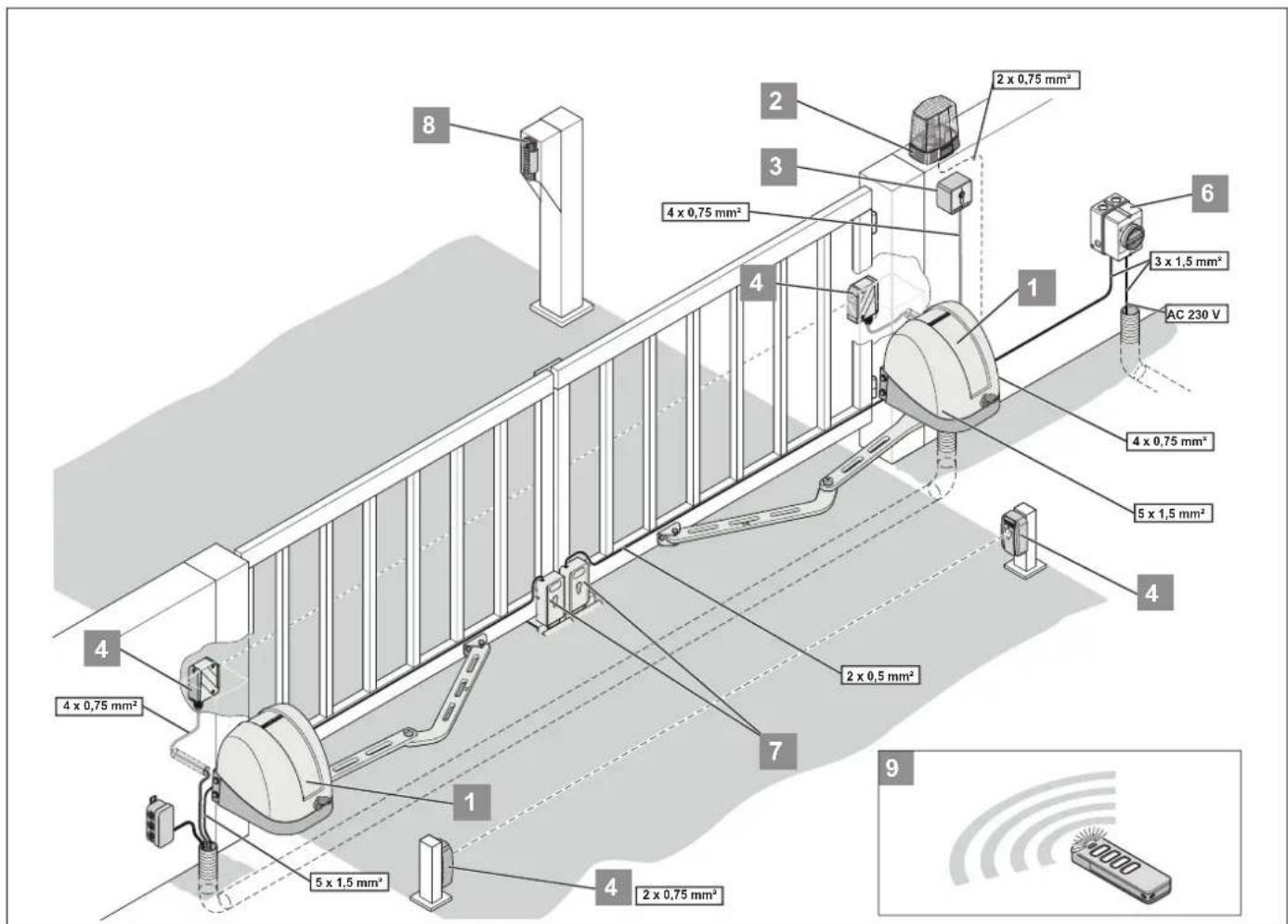
Fig.Applicationexample
1) Operator (master gate operator, slave gate operator)
2) Warning light (DC 22 V–34 V, max. 25 W)
3) Key switch (1 or 2 contacts)
4) Exterior photocell/interior photocell
5) Connecting cable set (12 m)
6) Main switch (all-pole deactivation)
7) Electric lock DC 24 V
A separate electric lock can be connected for each leaf.
8) Telecody
9) Handheld transmitter
1-wing swing gates can be operated with the electrically powered operator and the integrated control unit (master gate operator). The operator can also be used on 2-leaf swing gates in combination with an additional operator without a control unit (slave gate operator).
Optionally available accessories make it possible to adapt the operators to special characteristics of these gates. The operator can be controlled, for example, via a handheld transmitter.
The operator is mounted on the respective gate post and connected to the corresponding gate leaf with a hinged bracket. The rotating movement of the operator is transmitted to the gate leaf via the hinged bracket.
With 2-leaf gates, the control unit ensures compliance with the correct order when opening or closing the gate leaves.
3. Description of function and product
The operator is usually delivered in a set with a warning light. Accessories such as handheld transmitters and photocells are included in the scope of delivery.
The set is suitable for installation on gate posts.
The set for 2-leaf gates also contains a connection cable from operator to operator.
3.2 Safety equipment
The operator stops and reverses slightly if it encounters an obstacle. This prevents injury and damage to property. The gate will be partially or completely opened, depending on the setting.
If the power fails, the gate leaves can be unlocked and opened via an emergency release lever after opening the cover.
3.3 Product designation
natural_image
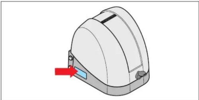
3D diagram of a mechanical component with a red arrow pointing to a blue component (no text or symbols)Fig. Type plate on the side of the bottom housing section
The type plate includes:
- type designation
- Item Number
• date of manufacture with month and year - serial number
In case of questions or service, please supply the type designation, the date of manufacture and the serial number.
3.4 Explanation of tool symbols
Tool symbols
These symbols refer to the use of tools required for installation.


Phillips screwdriver

Allen wrench

Fork or ring wrench

Ratchet wrench
3. Description of function and product
3.5 Scope of delivery
Scope of delivery of set for 1-wing gates
natural_image
3D diagram of a device with an open lid and internal components, labeled with number 1 (no text or symbols on the diagram itself)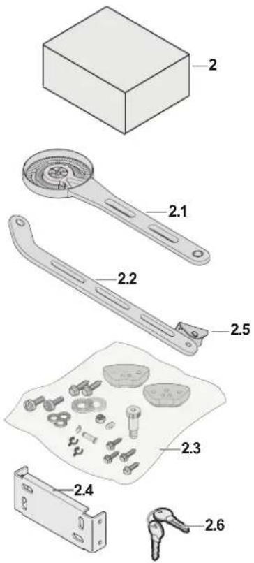

natural_image
Illustration of five different electronic devices with numbered labels (3, 4, 5, and an unlabeled figure), no visible text or symbols beyond labels.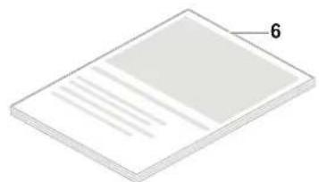
natural_image
Isometric view of a flat rectangular sheet with horizontal lines and a label '6' on the top right corner (no other text or symbols)Fig. Scope of delivery for 1-wing gates
1) Operator with control unit, 1x master gate operator
2) Accessory box
2.1) Operator arm, L = 480 mm
2.2) Gate arm, L = 460 mm
2.3) Bag with mounting material
- Blocking element, 2x
— Screw for blocking element, RIPP LOCK, M8 x 20 mm, 4x
— Washer, RIPP LOCK, ∅ = 8 mm, 4x
— Screw, RIPP LOCK, M10 x 35 mm
— Washer, RIPP LOCK, ∅ = 10 mm
— Fitting screw M12
— Washer M12
— Hexagonal nut, self-locking M12 - Connecting bolt
— Security pin
— Spacer clip, 2x
— Screw M8 x 16 mm, self-tapping, 4x
2.4) Post fitting
2.5) Gate leaf fitting
2.6) Key, 2x
3) Warning light (DC 22 V–34 V, max. 25 W)
4) Photocell complete set
5) Handheld transmitter
6) Installation and Operating Manual

INFORMATION
- Mounting material for installation on-site is not included in the scope of delivery.
Select suitable mounting material for the respective substructure.
3. Description of function and product
Scope of delivery of set for 2-leaf gates
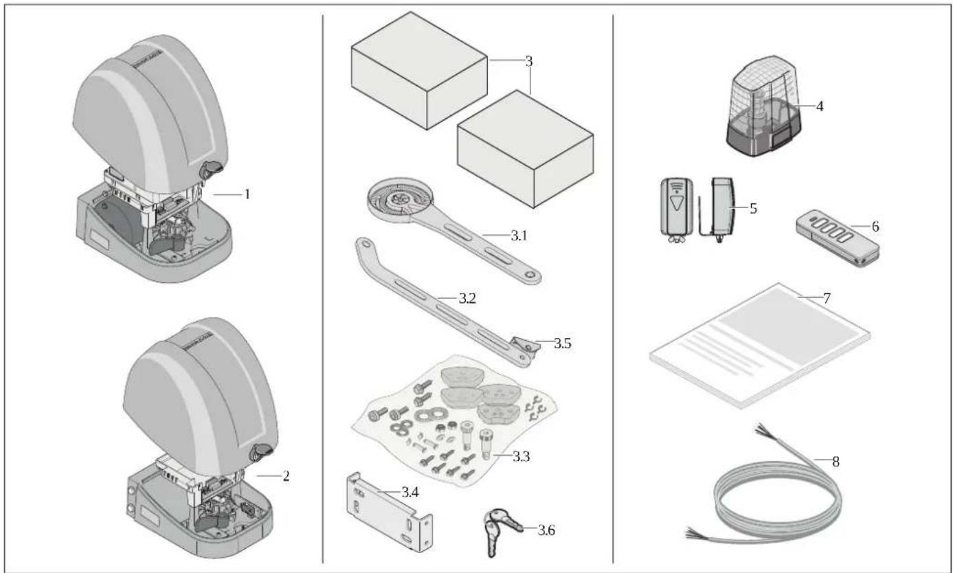
Fig. Scope of delivery for 2-leaf gates
1) Operator with control unit, 1x master gate operator
2) Operator without control unit, 1x slave gate operator
3) Accessory box, 2x
3.1) Operator arm, L = 480 mm, 2x
3.2) Gate arm, L = 460 mm, 2x
3.3) Bag with mounting material
— Blocking element, 4x
— Screw for blocking element, RIPP LOCK, M8 x 20 mm, 8x
— Washer, RIPP LOCK, ∅ = 8 mm, 8x
— Screw, RIPP LOCK, M10 x 35 mm, 2x
— Washer, RIPP LOCK, ∅ = 10 mm, 2x
— Fitting screw M12, 2 x
— Washer M12, 2x
— Hexagonal nut, self-locking M12, 2x
- Connecting bolt, 2x
— Security pin, 2x
- Spacer clip, 4x
— Screw M8 x 16 mm, self-tapping, 8x
3.4) Post fitting, 2x
3.5) Gate leaf fitting, 2x
3.6) Key, 2x
4) Warning light (DC 22 V–34 V, max. 25 W)
5) Photocell complete set
6) Handheld transmitter
7) Installation and Operating Manual
8) Connecting cable set, length 12 m
INFORMATION
- Mounting material for installation on-site is not included in the scope of delivery.
Select suitable mounting material for the respective substructure.
3. Description of function and product
Optional accessories
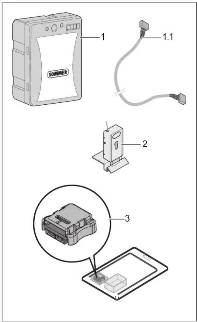
Fig. Optional accessories
1) Accumulator DC 24 V, 1.2 Ah
1.1) Connection cable for accumulator, L = 380 mm
2) Electric lock DC 24 V, optionally with cylinder
3) Memo, pluggable memory extension for radio receiver
The actual scope of delivery may vary depending on the customer specifications or version.
3.6 Technical data
| twist AM | |
| Mains voltage AC 220–240 V | |
| Rated frequency 50–60 Hz | |
| Memory positions in radio receiver | 40 |
| Duty cycle S3 = 15 % | |
| Operating temperature | -25 °C to +65 °C |
| Emission value according to operating environment | <50 dB(A) |
| IP protection class IP44 | |
| IP-code II | |
| Max. angular velocity | approx. 11 %s |
| Maximum torque per gate leaf | 120 Nm |
| Rated torque per gate leaf | 40 Nm |
| Rated power consumption per gate leaf | 85 W |
| Rated current consumption per gate leaf | 0.5 A |
| Power consumption in power-saving mode | >0.5 W |
| Maximum gate weight per leaf | 250 kg |
| Max. leaf length 2,500 mm | |
| Gate inclination 0 % | |
3. Description of function and product
3.7 Overview of gate operator
The exterior views of the master gate operator and the slave gate operator are identical.
Master gate operator from outside
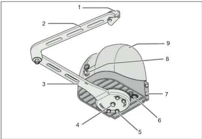
Fig. Exterior view of master gate operator, closed
1) Gate leaf fitting with connecting bolt and security pin, spacer clip, 2x
2) Gate arm
3) Operator arm
4) Screw, RIPP LOCK, M10 x 35 mm
5) Screws for blocking element, RIPP LOCK, M8 x 20 mm
6) Membrane bush
7) Screws M8 x 16 mm, self-tapping
8) Lever lock with dust cap
9) Cover
Master gate operator from inside
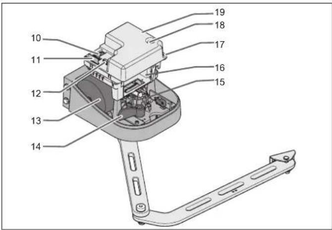
Fig. Overview of master gate operator, open
10) Buttons and DIP switch
11) Radio receiver
12) Memory module
13) Transformer
14) Emergency release lever
15) Motor with gearing system
16) Accumulator rack
17) Screws of the transparent protective cover for the control unit
18) Fuse
19) Transparent protective cover for the control unit
Slave gate operator from inside
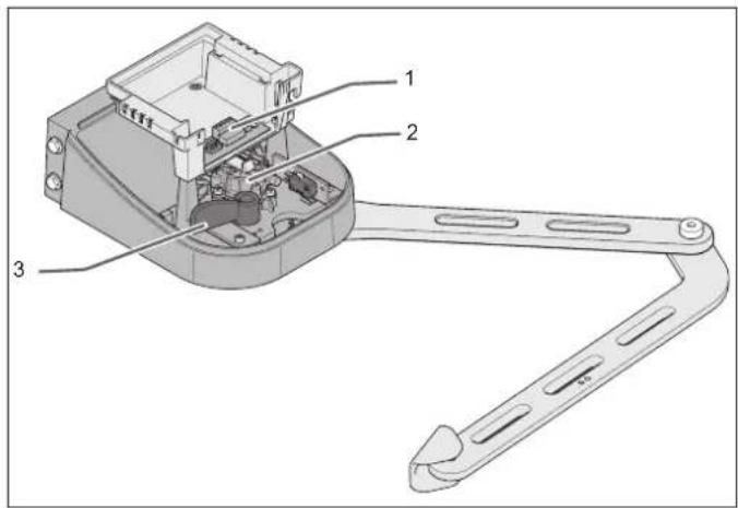
Fig. Overview of slave gate operator, open
1) Terminal blocks
2) Motor with gearing system
3) Emergency release lever
3. Description of function and product
3.8 Definitions
The following definitions are used in this document:
Master gate operator
Designates the operator with integrated control unit and transformer. The optional accumulator can also be installed in the master gate operator. We recommend installing the master gate operator on the side of the gate system with the power supply.
Slave gate operator
The slave gate operator mostly contains only the mechanical operator elements. It can be distinguished from the master gate operator by the type plate, the lack of a power cord and its lower weight.
Active leaf
Designates the gate leaf which opens first and closes second. The sequence of movements is necessary e.g. with a stop bar on a gate leaf. 1-leaf gates only have an active leaf.
Inactive leaf
Designates the gate leaf which opens second and closes first. 1-wing gate systems do not have inactive leaves.
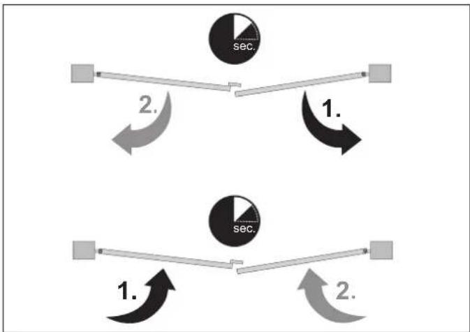
flowchart
graph TD
    A["Start"] --> B{Step 1}
    B --> C["Step 2"]
    C --> D["End"]
    style A fill:#f9f,stroke:#333
    style D fill:#bbf,stroke:#333
    subgraph Step 1
        E["sec."] --> F["End"]
    end
    subgraph Step 2
        G["sec."] --> H["End"]
    end
Fig. Example of movement sequence
Left gate/right gate
In this Installation and Operating Manual, it is always assumed that the gate is viewed from the interior of the property. The operators are situated inside the property. The gate opens into the property. When installing the operators, you must decide in which direction the gate will open and close.
3.9 Dimensions and weights
Dimensions of gate leaf fitting
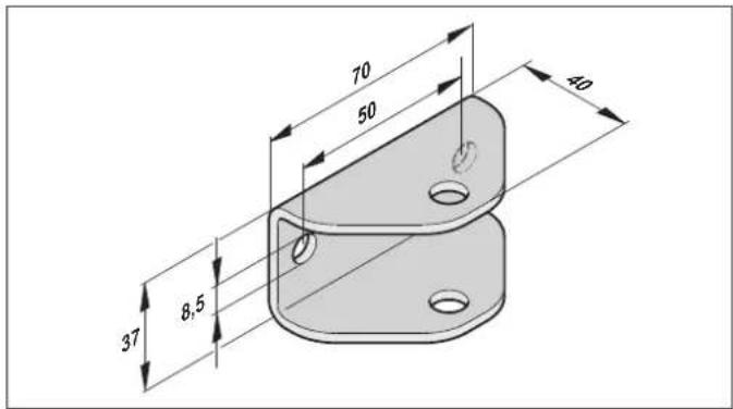
Fig. Dimensions of gate leaf fitting
Dimensions of post fitting
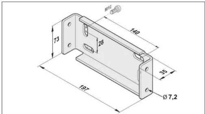
Fig. Dimensions of post fitting
Dimensions of master and slave gate operator
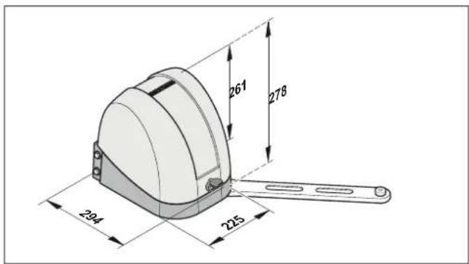
Fig. Dimensions of master and slave gate operator
4. Tools and protective equipment
5. Declaration of Installation
4.1 Required tools and personal protective equipment
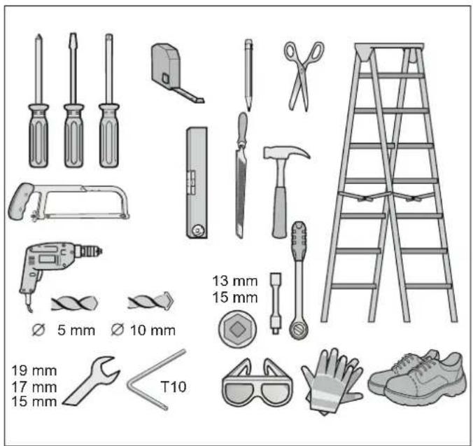
Fig. Recommended tools and personal protective equipment for installation
| Tools Size | |
| Phillips screwdriver PH2 | |
| Flat head screwdriver 3.5 mm | |
| Allen wrench 8 mm | |
| Fork or ring wrench 15/17/19 mm | |
| Ratchet 1/2" | |
| Torque wrench 1/2" | |
| Ratchet insert 13/15 mm |
To assemble and install the operator, you will require the tools shown and described above. Lay out the required tools beforehand to ensure fast and safe installation. Wear your personal protective equipment. This includes safety glasses, safety gloves and safety shoes.
Declaration of Installation
for installation of an incomplete machine in accordance with the Machinery Directive 2006/42/EC, Annex II, Part 1 B
hereby declares that the swing gate operators
twist AM
have been developed, designed and manufactured in conformity with the:
• Machinery Directive 2006/42/EC
• Low Voltage Directive 2014/35/EU
• Electromagnetic Compatibility Directive 2014/30/EU
• RoHS Directive 2011/65/EU.
The following standards were applied:
EN ISO 13849-1, Safety of machines – Safety-related parts PL "C" Cat. 2 of controls
– Part 1: General design guidelines
EN 60335-1/2, Safety of electrical appliances/operators where applicable for gates
EN 61000-6-3 Electromagnetic compatibility (EMC) – interference
EN 61000-6-2 Electromagnetic compatibility (EMC) – interference resistance
EN 60335-2-103 General safety requirements for household and similar electrical appliances
– Part 2: Special requirements for operators for gates, doors and windows
The following requirements of Annex 1 of the Machinery Directive 2006/42/EC are met: 1.1.2, 1.1.3, 1.1.5, 1.2.1, 1.2.2, 1.2.3, 1.2.4, 1.2.5, 1.2.6, 1.3.1, 1.3.2, 1.3.4, 1.3.7, 1.5.1, 1.5.4, 1.5.6, 1.5.14, 1.6.1, 1.6.2, 1.6.3, 1.7.1, 1.7.3, 1.7.4
The special technical documentation was prepared in accordance with Annex VII Part B and will be submitted to regulators electronically on request.
The incomplete machine is intended solely for installation in a gate system to form a complete machine as defined by the Machinery Directive 2006/42/EC. The gate system may only be put into operation after it has been established that the complete system complies with the EC Directives listed above.
The undersigned is responsible for compilation of the technical documents.
Jochen Lude Responsible for documents
6.1 Important notes and information
In particular, please observe and comply with the following warnings, notes and information to ensure safe installation.

DANGER

Danger if not observed!
If warnings are not observed, serious injury or death may result.
▶ All warnings must be complied with.

WARNING

Danger due to projecting parts!
Parts projecting into roads or public footpaths may seriously injure or kill persons or animals.
- Keep public roads and footpaths clear of projecting parts.

Danger due to unstable falling parts!
Unstable posts or gate leaves or an improperly installed operator can tip over. Persons or animals may be struck by these parts. Severe injuries or death may result.
Posts, gate leaves and installed operators must be stable. Suitable mounting material must be used to attach the operator to the gate post and the gate.

Danger of crushing and shearing!
If the gate moves with persons or animals in the movement area, crushing and shearing injuries may be caused by the mechanism and safety edges of the gate.
▶ Only use the operator when you have a direct view of the gate.
▶ All danger zones must be visible during the entire gate operation.
▶ Always keep the moving gate in sight.
▶ Keep persons and animals clear of the range of movement of the gate.
▶ Never put your hand near the gate when it is moving or near moving parts.
▶ Do not drive through the gate until it has opened completely.
▶ Never stand in the opened gate.

Danger of tripping and falling!
Unsafely positioned parts such as packaging, operator parts or tools may cause trips or falls.
- Keep the installation area free of unnecessary items.
Place all parts where no-one is likely to trip or fall over them.
The general workplace guidelines must be observed.

Risk of eye injury!
Chips flying when drilling may cause serious injuries to eyes and hands.
▶ Wear safety glasses.


Risk of injury to feet!
Falling parts can cause foot injuries.
▶ Wear safety shoes.


CAUTION

Risk of injury to hands!
Rough metal parts may cause abrasions and cuts when picked up or touched.
▶ Wear safety gloves.


NOTE
- If the gates or the gate posts are unstable, parts could break off or the operator could fall. Objects may be damaged.
Gates and gate posts must be stable.
- To prevent damage to the gate or operator, use only suitable and approved fastening materials such as wall plugs or screws.
The mounting material must be suitable for the material of the gates and gate posts.
- Damage to the gate system can occur if the gate leaves are relatively large or the leaf filling level is high and there is high wind pressure.
We recommend using electric locks for secure locking.
6. Installation

NOTE
In order to maintain the functionality of the technical equipment, we recommend that you observe the specified maximum lengths and minimum cross-sections for power cables!
Connection lines Signal lines
Maximum length 20 m Maximum length 25 m
Minimum cross-section 1.5 mm ^4
Approved wire cross sections for all terminals: 1 mm ^2 to 2.5 mm ^2 .
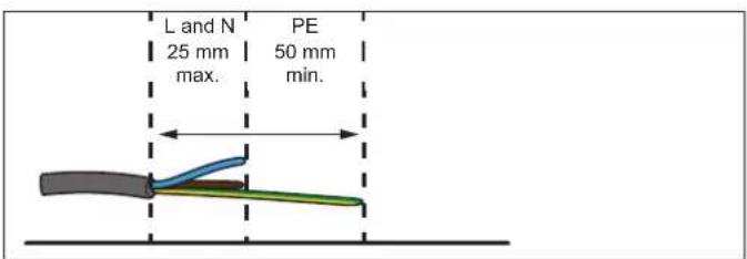
- Do not remove the sheath of the supply line until it is in the housing!
- Insert the sheath of the connecting line into the control unit housing.
- Remove the line sheaths as shown in the graphic.
6.2 Preparing for installation
Check the existing gate mechanism and installation posts
Before beginning installation, ensure that the operator is suitable for the existing gate system. The existing gate system must meet the following criteria:
• Gate length of a leaf 800 mm to 2,500 mm
• Maximum gate height 2,000 mm Maximum weight of an individual gate leaf 250 kg
• Weight should be evenly distributed
- It must be possible to move the gate leaf easily by hand over the entire swivel range
- The gate leaf must stand still in every position and must not move independently into a default state.
- Not suitable for inclined gates.
• Stable installation posts
- Closed area on the gate leaf must not be larger than the maximum allowed cover, see the table below.
Height (m) Filling level [%]
| 2.0 100 80 40 30 | |||
| 1.5 100 100 60 40 | |||
| 1.0 100 100 80 50 | |||
| Length (m) | 1.0 1.5 2.0 2.5 |
Tab. Relation of gate surface to filling level
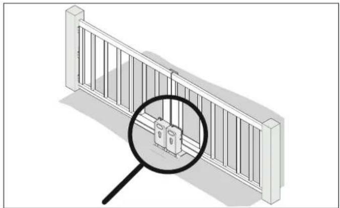
Use of electric locks
natural_image
Illustration of a railing with a magnified inset showing internal components (no text or symbols)Fig. Installation example for electric locks
To lock the gate securely, a separate electric lock is recommended for every gate leaf. This applies in particular for gate lengths of over 2,000 mm.
The following requirements must be complied with: DIN EN 1991-1-4 Wind pressure, with values 32.3 m/s, wind zone 2, and 11 on the Beaufort scale.

NOTE
• Strong wind can push the gate open. This may cause damage to the operator or the gate system.
The use of an electric lock in addition is recommended for relatively large gate leaves or gate leaves with high filling levels.
Fastening dimensions on posts

WARNING
Danger of crushing and shearing!
If the gate moves with persons or animals in the movement area, crushing and shearing injuries may be caused by the mechanism and safety edges of the gate.
The required safety distances to fixed elements must comply with standards including EN 13241-1. The respective country-specific requirements must be observed.
The following criteria must be fulfilled for mounting on the gate:
- Post dimensions must be at least 25 × 25 cm.
- Material of the posts must have sufficient strength for the forces generated.
- The installation position of the fittings must be within the permitted values of dimensions A/B/C/D.
A (mm) B (mm) C (mm) D (mm) Angle
| 200 | 155 720 | 290 | 90^ | |
| 200 715 | 305 | |||
| 250 705 | 315 | |||
| 300 694 | 325 | |||
| 350 678 | 325 | |||
| 400 660 | 315 | |||
| 450 639 | 280 | |||
| 225 | 420 110°155 | 695 380 | 100^ | |
| 275 645 | ||||
| 350 570 | 440 | 120^ | ||
| 400 519 | 445 130° |
Tab. Permitted specifications of dimensions A/B/C/D and the corresponding opening angles
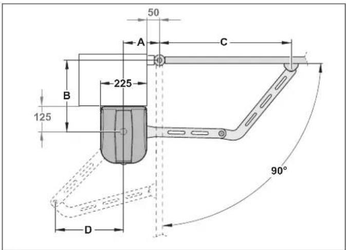
Fig. Dimensions A/B/C/D, opening angle 90°
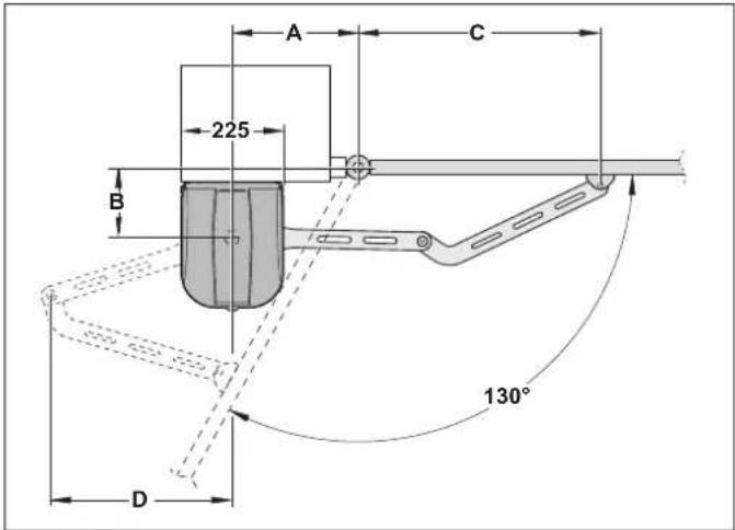
Fig. Dimensions A/B/C/D, max. opening angle 130°
- If the opening angles of the two gate leaves deviate, dimensions A/B/C/D must be selected appropriately.
- The safety distances comply with the standard for the gate type.
- The intended installation surface on the post must be vertical and flat. The post fitting must be positioned flat during installation. Uneven areas or slopes must be flattened out before installation.

INFORMATION
• Overextension of the gate arm can be prevented in the case of deviating dimensions. To do so, the defined position for the gate fitting must be shifted 15 mm towards the gate post with the gate arm extended.
Removing unsuitable components
Before installation remove:
- All manual locking systems, e.g. gate locks
- Dampers or spring elements.

NOTE
- If attached parts, e.g. bolts or locks, are installed on a gate, they may block the operator. This may cause faults or damage to the operator.
Before installing the operator, remove all unsuitable attached parts or reliably disable them.
Definition of master/slave gate operator
In the case of 2-leaf gate systems, the position of the master gate operator must be defined before beginning installation. We recommend installing the master gate operator on the side of the gate with the power supply.
6. Installation
6.3 Pre-assembling the operator arm
Mechanical stops, so-called blocking elements, can be installed in the operator arm. These are additional safeguards for the gate system. The blocking elements can be omitted if fixed stops are present.

NOTE
- The operator switches off via fixed stops. Fixed stops are required for gate OPEN and gate CLOSE. The existing stops on the gate system must be used as fixed stops.
The supplied blocking elements can be used in addition to the existing fixed stops. This is an additional safeguard for the gate system.
Use of the blocking elements
| Blocking element in the gate arm | Left gate Right gate | |
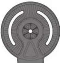 | Fixed stops present in the gate system for gate OPEN and gate CLOSE | |
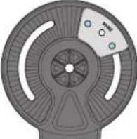 *1 *1 | Blocking element in addition to gate OPEN fixed stop | Blocking element in addition to gate CLOSE fixed stop |
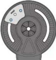 *1 *1 | Blocking element in addition to gate CLOSE fixed stop | Blocking element in addition to gate OPEN fixed stop |
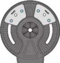 *1 *1 | Blocking elements in addition to gate OPEN and gate CLOSE fixed stops | |
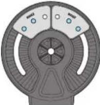 *2 *2 | ||
*1 Blocking element is mounted on the two outer threads.
*2 Blocking element is mounted on the centre and on one outer thread. This installation option extends the possible swivel area of the gate arm.
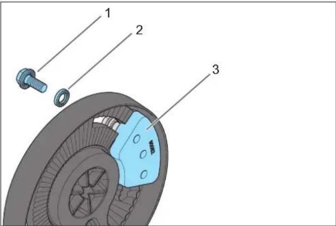
Fig. Installation example for the blocking element
1) Screw for blocking element, RIPP LOCK, M8 x 20 mm
2) Washer, RIPP LOCK, ∅ = 8 mm
3) Blocking element
Installing the blocking element
- Insert the blocking element into the operator arm and attach with 2 screws and 2 washers. To do so, use the screws M8 x 20 mm and the washer, ∅ = 8 mm, for the blocking element. It must still be possible to shift the blocking element in the cut-out.
- If necessary, install the second blocking element accordingly.
6. Installation
6.4 Installing the operator arm
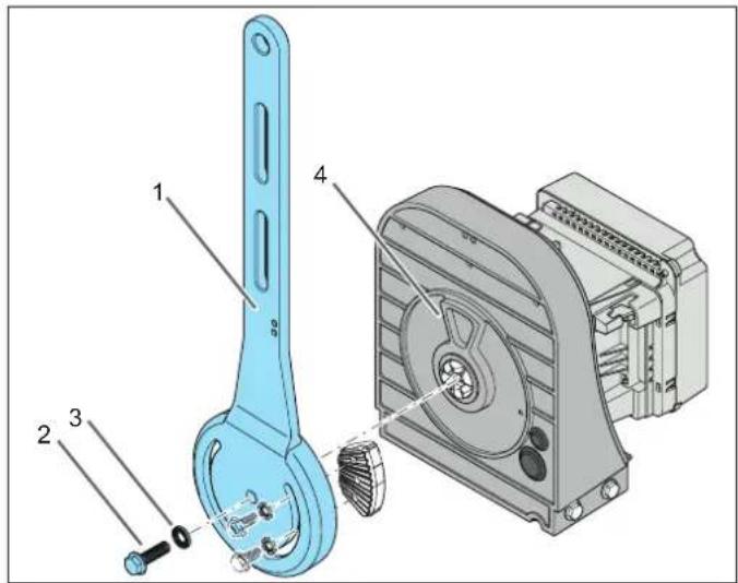
Fig. Installation example for the operator arm with one blocking element
1) Operator arm
2) Screw, RIPP LOCK, M10 x 35 mm
3) Washer, RIPP LOCK, = 10 mm
4) End stop for the blocking element
Installing the operator arm
- Position the operator upright as shown in the diagram.

WARNING! Danger of crushing and shearing!
When tightening the screws, the operator arm can rotate in the screwing direction and hit people. This may cause crushing or shearing injuries.
When tightening the screws, hold the upper section of the operator arm against the direction of rotation.
- Hold the operator arm approximately vertically and observe the position of the holes.
Using screw M10 x 35 mm and the washer, = 10 mm, screw the operator arm to the operator. Tightening torque 75 Nm. Ensure that the parts are friction-locked.
6.5 Installing the post fitting
The position of the post fitting is dependent on various factors:
- Height of the gate leaf fitting "13.4 Troubleshooting table".
- Opening angle of the gate.
- Comply with dimensions A/ B/ C/ D, see Chapter "6.2 Preparing for installation", section "Fastening dimensions on posts".
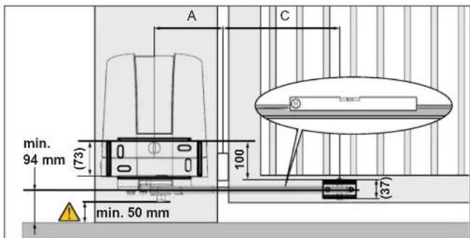
Fig. Dimensions of fittings
- Determine the vertical position of the gate leaf fitting.
- The position for the gate leaf fitting must be fixed and stable.
- The centre of the gate leaf fitting must be at least 94 mm from the ground.
- The screws on the underside of the gate arm must be accessible.
- Determine and mark the horizontal position of the gate leaf fitting.
Comply with the permissible dimensions A/ B/ C/ D, see Chapter "6.2 Preparing for installation", section "Fastening dimensions on posts". - Determine the position of the post fitting. There must be enough space above the cover to allow you to remove it.
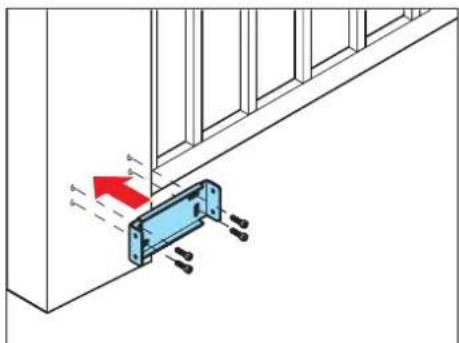
natural_image
Diagram showing a blue bracket with bolts and a red arrow indicating force or displacement (no text or symbols)Fig.4
- Align the post fitting vertically and horizontally and install on the post with suitable and permissible mounting materials. The short splay on the post fitting must point upwards.
6. Installation
6.6 Installing the operator
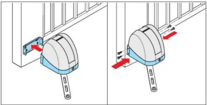
natural_image
Illustration of two mechanical device components with red arrows indicating motion, mounted on a panel (no text or symbols present)Fig. 1 Fig. 2

CAUTION! Risk of injury to feet!
Falling parts can cause foot injuries.
▶ Wear safety shoes.
▶ Hold the operator firmly until all 4 screws are tightly screwed in.
- Position the operator on the post fitting or fasten it.provisionally.
- Lightly grease self-tapping screws M8 x 16 mm. Fasten the operator to the post fitting with the 4 screws. Tightening torque 20 Nm. The bore holes on the post fitting do not have pre-cut threads.
6.7 Installing the gate arm
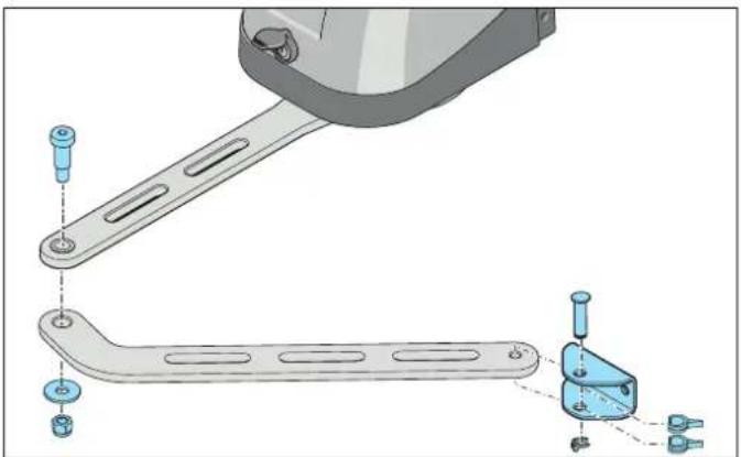
natural_image
Technical illustration of a mechanical assembly with two views: top view shows a bracket and plate, bottom view shows a handle with fasteners (no text or symbols)Fig. Gate arm installation, left gate
- Hold the gate arm so that the bent part points towards the operator. The gate arm is always installed below the operator arm.
- Attach the gate arm to the operator arm with the fitting screw M12, the washer and the self-locking hexagonal nut. Tightening torque 80 Nm.
-
Using suitable materials, fasten the gate leaf fitting provisionally in the defined position on the gate leaf.
-
Lightly grease the connecting bolt.
- Slide the gate leaf fitting over the gate arm and position the two spacer clips as shown in the illustration.
- Insert the connecting bolt and secure it with the security pin.
6.8 Checking for freedom of movement

DANGER

Danger due to electric current!
Contact with live parts may result in electric current flowing through the body.
Electric shock, burns or death may result.
▶ All work on electrical components must be carried out by a trained electrician.
The operator must be disconnected from the power supply before working on it.
▶ If an accumulator is connected, disconnect it from the control unit.
▶ Check that the operator is not live.
- Secure the operator against being switched back on.

NOTE
- The activities in this section must be performed with the system disconnected from the mains voltage.
Unplug the accumulator if necessary.
This prevents damage to the operator.
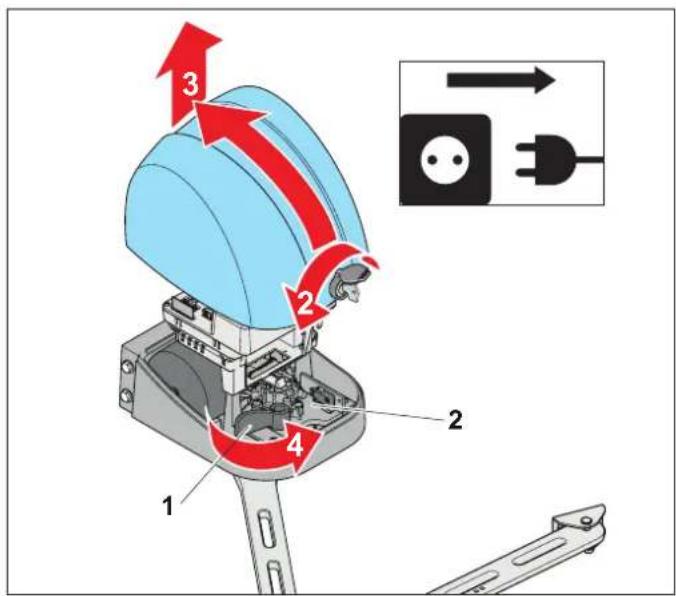
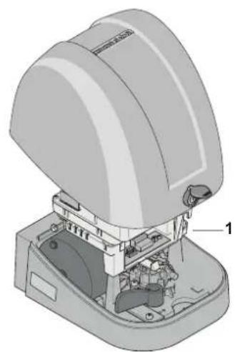
Fig. Bottom section of housing – emergency release lever (1), motor plate (2)
- Disconnect the operator from the mains voltage, see Chapter "7.2 Disconnect the control unit from the mains voltage".
- Open the dust cap.
Insert the key and turn it 90^ to the left.
- Tilt the cover slightly towards the rear and remove it in upward direction.
- Turn the emergency release lever (1) at the front stop.
⇒ The motor plate (2) moves back.
⇒ The operator is released from the gate arm.

INFORMATION
- If an electric lock was used, release it separately, see separate instructions.
- Check whether blocking elements are installed in the gate arm and whether they can be moved.
Otherwise, slightly unscrew the screws of the blocking elements.

INFORMATION
- If the blocking elements of the operator are used in addition to the fixed stops on the gate, see Chapter "6.9 Adjusting the blocking elements"
-
The distance between the rotation point on the gate leaf fitting and the rotation point of the gate arm must be at least 15 mm smaller than the extended length of the operator arm and the gate arm. See Chapter "6.2 Preparing for installation", section "Table of dimensions A/B/C/D".
-
Carefully open and close the gate several times by hand.
As you do so, check the following:
- Nothing jams.
• The gate arm always remains horizontal.
• The intended end positions are reached. - Safety distances in accordance with EN 13241 must be observed at all times.
- Fixed stops for gate OPEN and gate CLOSE.
- Finally, the gate position can be fine-tuned by moving the gate leaf fitting.
6.9 Adjusting the blocking elements
The supplied blocking elements for gate CLOSE and gate OPEN can be used in addition to the existing fixed stops. The blocking elements can be omitted if fixed stops are present.
Setting gate OPEN blocking element
- Ensure that the operator is unlocked with the emergency release lever and that the gate leaf fitting is provisionally fixed to the gate.
- Move the gate to the intended end position for gate OPEN.
- Slide the blocking element with the associated screws forward on the side facing the gate as far as the perceptible stop. For assignment of the blocking elements, see Chapter "6.3 Pre-assembling the operator arm".
- Tighten the screws of the blocking element.
The end position for gate OPEN is dependent on the detent mechanism on the blocking element and can be set in the frame of the detent mechanism.
- Check whether the gate OPEN end position is correct.
If necessary, loosen the screws of the blocking element and move the blocking element one catch.
Setting gate CLOSE blocking element
- Ensure that the operator is unlocked with the emergency release lever and that the gate leaf fitting is provisionally fixed to the gate.
- Move the gate to the intended end position for gate CLOSE. With 2-leaf gates, make sure that they are lined up.
- Using the M8 x 20 mm screws, slide the blocking element forwards on the side of the gate facing away from you as far as the perceptible stop.
For assignment of the blocking elements, see also Chapter "6.4 Installing the operator arm".
- Tighten the screws of the blocking element.
The end position for gate CLOSE is dependent on the detent mechanism on the blocking element and can be set in the frame of the detent mechanism.
- Check whether the gate end position is correct.
If necessary, loosen the provisional fastening of the gate leaf fitting and slide the gate leaf fitting slightly in horizontal direction. Changing the position of the gate leaf fitting can also change the end position of the open gate.
The position of the gate CLOSE blocking element must then be corrected.
6. Installation
6.10 Installing the gate leaf fitting
natural_image
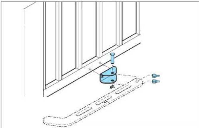
Diagram of a mechanical device mounted on a wall, with dashed lines indicating motion or path (no text or symbols)Fig. Installation example for the gate leaf fitting
When the freedom of movement has been checked and if necessary, the blocking elements set, the gate leaf fitting can be fixed firmly to the gate.
- Mark the position of the gate leaf fitting on the gate.
- Remove the connecting bolts on the gate leaf fitting.
- Align the gate leaf fitting vertically and horizontally and install on the gate with suitable and permissible mounting materials.
- Slide the gate leaf fitting over the gate arm and position the two spacer clips as shown in the illustration.
- Insert the connecting bolt and secure it with the security pin.
6.11 Installing accessories
Only SOMMER accessories may be connected. The accessories, e.g. warning light or photocell, come with separate instructions.
Position of photocells
We recommend installing the supplied photocell outside. As an option, a second photocell can be installed inside for additional functions; see application example in Chapter "3.1 The operator and its mode of operation". Select the position of the photocell so that the movement of the gate leaf does not interrupt the light beam, see "7.10 Connecting photocells".

NOTE
- We recommend installing a second photocell inside and outside at an installation height of e.g. 600 mm. This makes it possible to also secure larger vehicles.
7.1 Testing the provisional connection
Work on the electrical system and live parts may only be performed by a trained electrician. Please observe and comply with all instructions to ensure safe installation.

DANGER

Danger due to electric current!
Contact with live parts may result in electric current flowing through the body.
Electric shock, burns or death may result.
▶ All work on electrical components must be carried out by a trained electrician.
Before initial operation, ensure that the voltage of the power source matches the voltage listed on the type plate.
The operator must be disconnected from the power supply before working on it.
▶ If an accumulator is connected, disconnect it from the control unit.
▶ Check that the operator is not live.
- Secure the operator against being switched back on.

WARNING
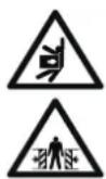
Danger of crushing and shearing!
If the gate moves with persons or animals in the movement area, crushing and shearing injuries may be caused by the mechanism and safety edges of the gate.
▶ Only use the operator when you have a direct view of the gate.
▶ All danger zones must be visible during the entire gate operation.
▶ Always keep the moving gate in sight.
▶ Keep persons and animals clear of the range of movement of the gate.
▶ Never put your hand near the gate when it is moving or near moving parts.
▶ Do not drive through the gate until it has opened completely.
▶ Never stand in the opened gate.

NOTE
- To prevent damage to the operator, do not connect the control unit to the power supply until installation is complete.
- The master gate operator is delivered with a connected power cord for adjustment work and provisional initial operation.
This power cord must be removed after initial operation and replaced with a fixed mains connection with a mains circuit breaker. Otherwise, the operator will be damaged.
The master gate operator is equipped with a power cord at the factory for tests and initial operation.
This power cord with plug is not suitable for continuous use. After initial operation, the power cord must be replaced, see chapter “7.16 Connecting mains power supply”.
The power outlet for the power cord must be protected by a fuse. Local and national installation regulations (e.g. VDE) must be observed.
7.2 Disconnect the control unit from the mains voltage
In particular, observe the warnings below.

DANGER

Danger due to electric current!
Contact with live parts may result in electric current flowing through the body.
Electric shock, burns or death may result.
▶ All work on electrical components must be carried out by a trained electrician.
The operator must be disconnected from the power supply before working on it.
▶ If an accumulator is connected, disconnect it from the control unit.
▶ Check that the operator is not live.
- Secure the operator against being switched back on.

WARNING

Danger due to hot parts!
After frequent operation, the motor and control unit may become hot. If the cover is removed and hot parts are touched, they may cause burns.
▶ Allow the operator to cool down before removing the cover.

NOTE
- Objects in the movement area of the gate may be jammed and damaged.
Objects must not be in the range of movement of the gate.

INFORMATION
- The terminals on the circuit board of the control unit are pluggable.
- Disconnect the control unit from the mains voltage.
- If installed, pull off the connecting cable on the accumulator.
- Only then can the screws of the transparent protective cover can be removed with a Phillips screwdriver.
- Remove the transparent protective cover.
7. Electrical connection and special functions
7.3 Overview of control unit
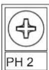
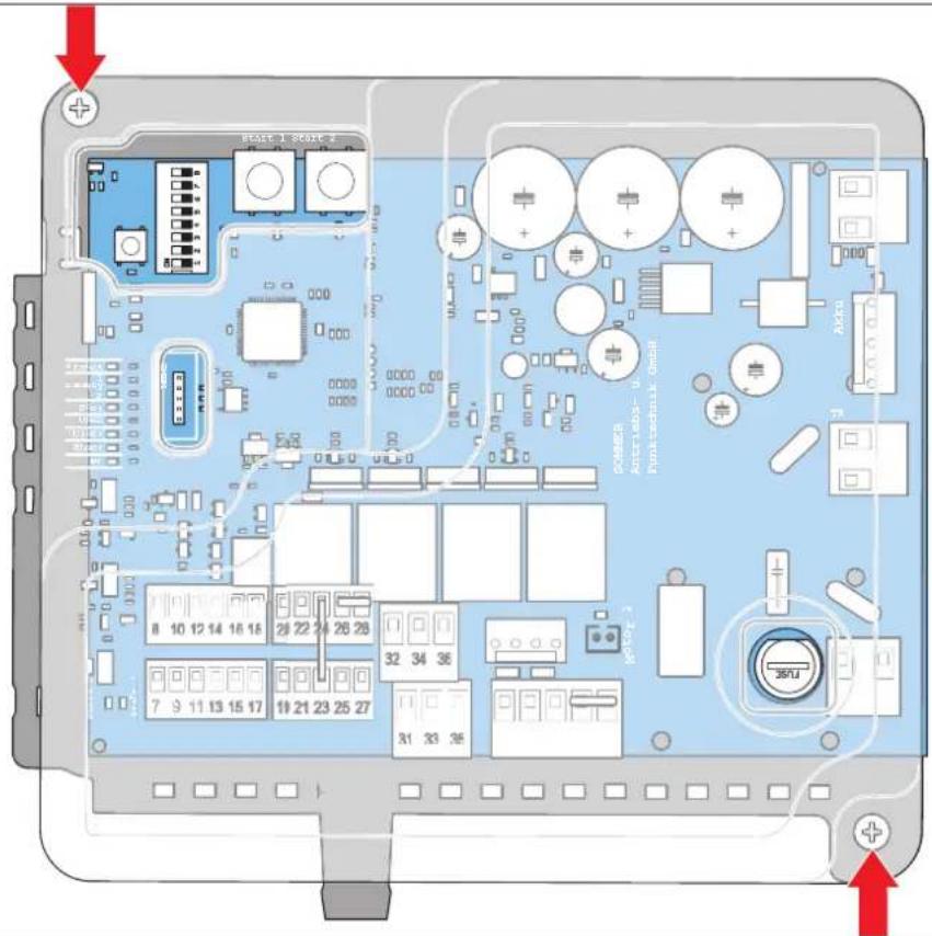
Fig. Control unit with transparent protective cover

DANGER

Danger due to electric current!
When the transparent protective cover of the control unit is removed, there is access to dangerous electrical voltage.
Contact with live parts may result in electric current flowing through the body.
Electric shock, burns or death may result.
The transparent protective cover of the control unit may only be removed by a trained electrician.
The control unit is protected with a transparent cover. The LED displays on the circuit board are visible through this transparent cover. Elements necessary for the user are accessible through cut-outs in the protective cover. Only a trained electrician may remove the transparent protective cover of the control unit and make changes in the accessible areas.
7. Electrical connection and special functions
7.4 Connection options on the master and slave gate operator
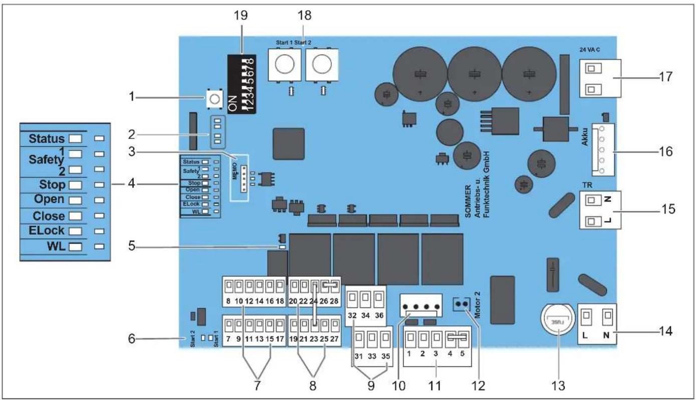
Fig. on of components and connections of the master gate operator
Circuit board for master gate operator
| 1 Radio button (radio) | 16 Terminal for accumulator, pluggable connection, cannot be interchanged |
| 2 LEDs (red), CH 1–4, display for radio channel | 17 Secondary voltage transformer, connected in factory state |
| 3 Slot for extended radio memory (Memo) | 18 “START 1” and “START 2” button, for left and right motor |
| 4 LEDs for status (green), safety devices (yellow) and functions (green) | 19 DIP switch configuration |
| 5 LED (yellow) for status of multi-function relay (MUFU) | Slave gate operator circuit board[IMAGE]Fig. Position of components and connections of theslavegate operator |
| 6 LEDs (yellow) for external start button | |
| 7 Connections for safety and monitoring devices | |
| 8 Connections for control elements | |
| 9 Connections for warning light and electric locks | |
| 10 Motor connection formastergate operator/Motor 2 | |
| 11 Motor connection forslavegate operator/Motor 1,in factory state with a jumper between PIN 4 and 5 | |
| 12 Signal of emergency release on themastergate operator, connected in factory state | |
| 13 Fuse (5 x 20 mm, 1.6 A T) | 1 Motor connection forslavegate operator, connected in factory state |
| 14 Mains power (L, N), AC 220–240 V | 2 Terminal for connection cable (mastergate operator/slavegate operator) |
| 15 Primary voltage transformer, connected in factory state | 3 Signal of emergency release on theslavegate operator, connected in factory state |
7.5 Overview of the LEDs
The flash sequences show information on malfunctions for technicians, end customers and telephone support.
| LED Flash sequence Cause | ||
| Status(green) | □ Off | · Operating voltage absent or power-saving mode activated |
| ■ On | · Operating voltage is connected/operator is in normal mode | |
| ■ ■ ■ ■ ■ ■ ■ ■ ■ ■ ■ ■ ■ ■ ■ ■ ■ ■ ■ ■ ■ ■ ■ ■ ■ ■ ■ ■ ■ ■ ■ ■ ■ ■ ■ ■ ■ ■ ■ ■ ■ ■ ■ ■ ■ ■ ■ ■ ■ ■ ■ ■ ■ ■ ■ ■ ■ ■ ■ ■ ■ ■ ■ ■ ■ ■ ■ ■ ■ ■ ■ ■ ■ ■ ■ ■ ■ ■ ■ ■ ■ ■ ■ ■ ■ ■ ■ ■ ■ ■ ■ ■ ■ ■ ■ ■ ■ ■ ■ ■ ■ □ Off | · Normal operation, flashes while gate is moving· Programming mode activated· Pre-warning time activated· During reversing movement or soft reversal· Waiting for confirmation during the gate CLOSE position programming run· Fault display· Safety device not OK before movement· Safety device interrupted during movement· Interrupted safety device, see chapter “11.8 Jog mode in the event of faults”· Display of a fault, see Chapter “13.4 Troubleshooting table”· Service required (e.g. pre-set limit value reached) | |
| ■ ■ ■ ■ ■ ■ ■ ■ ■ ■ ■ ■ ■ ■ ■ ■ ■ ■ ■ ■ ■ ■ ■ ■ ■ ■ ■ ■ ■ ■ ■ ■ ■ ■ ■ ■ ■ ■ ■ ■ ■ ■ ■ ■ ■ ■ ■ ■ ■ ■ ■ ■ ■ ■ ■ ■ ■ ■ ■ ■ ■ ■ ■ ■ ■ ■ ■ ■ ■ ■ ■ ■ ■ ■ ■ ■ ■ ■ ■ ■ ■ ■ ■ ■ ■ ■ ■ ■ ■ ■ ■ ■ ■ ■ ■ □ Off | · No safety device connected in exterior· Safety device detected in exterior· Safety device in exterior interrupted/fault | |
| SAFETY 1(yellow) | ■ On | · Safety device detected in exterior· Safety device in exterior interrupted/fault |
| ■ ■ ■ ■ ■ ■ ■ ■ ■ ■ ■ ■ ■ ■ ■ ■ ■ ■ ■ ■ ■ ■ ■ ■ ■ ■ ■ ■ ■ ■ ■ ■ ■ ■ ■ ■ ■ ■ ■ ■ ■ ■ ■ ■ ■ ■ ■ ■ ■ ■ ■ ■ ■ ■ ■ ■ ■ ■ ■ ■ ■ ■ ■ ■ ■ ■ ■ ■ ■ ■ ■ ■ ■ ■ ■ ■ ■ ■ ■ ■ ■ ■ ■ ■ ■ ■ ■ ■ ■ ■ ■ ■ ■ ■ ■■ ■ ■ ■ ■ ■ ■ ■ ■ ■ ■ ■ ■ ■ ■ ■ ■ ■ ■ ■ ■ ■ ■ ■ ■ ■ ■ ■ ■ ■ ■ ■ ■ ■ ■ ■ ■ ■ ■ ■ ■ ■ ■ ■ ■ ■ ■ ■ ■ ■ ■ ■ ■ ■ ■ ■ ■ ■ ■ ■ ■ ■ ■ ■ ■ ■ ■ ■ ■ ■ ■ ■ ■ ■ ■ ■ ■ ■ ■ ■ ■ ■ ■ ■ ■ ■ ■ ■ ■ ■ ■ ■ ■ ■ ■ ■ ■ ■ ■ ▢ Off | · No safety device connected in exterior· Safety device detected in exterior· Safety device in exterior interrupted/fault· No safety device connected in interior· Safety device detected in interior· Safety device in interior interrupted/fault | |
| SAFETY 2(yellow) | ■ On | · Safety device detected in interior· Safety device in interior interrupted/fault |
| ■ ■ ■ ■ ■ ■ ■ ■ ■ ■ ■ ■ ■ ■ ■ ■ ■ ■ ■ ■ ■ ■ ■ ■ ■ ■ ■ ■ ■ ■ ■ ■ ■ ■ ■ ■ ■ ■ ■ ■ ■ ■ ■ ■ ■ ■ ■ ■ ■ ■ ■ ■ ■ ■ ■ ■ ■ ■ ■ ■ ■ ■ ■ ■ ■ ■ ■ ■ ■ ■ ■ ■ ■ ■ ■ ■ ■ ■ ■ ■ ■ ■ ■ ■ ■ ■ ■ ■ ■ ■ ■ ■ □ Off | · EMERGENCY STOP not triggered· EMERGENCY STOP triggered | |
| Stop(green) | ■ On | · Operator not running in gate OPEN direction |
| Open(green) | □ Off | · Operator running in gate OPEN direction |
| ■ On | · Operator is deactivated | |
| Close(green) | □ Off | · Operator running in gate CLOSE direction |
| ■ On | · Electric lock is unlocked· Electric lock is locked | |
| ELock(yellow) | □ Off | · Operating voltage absent, power-saving mode activated |
| ■ On | · Warning light is triggered/activated· Gate movement is displayed, no other status indication possible | |
| Warninglight, WL(yellow) | ■ ■ ■ ■ ■ ■ ■ ■ ■ ■ ■ ■ ■ ■ ■ ■ ■ ■ ■ ■ ■ ■ ■ ■ ■ ■ ■ ■ ■ ■ ■ ■ ■ ■ ■ ■ ■ ■ ■ ■ ■ ■ ■ ■ ■ ■ ■ ■ ■ ■ ■ ■ ■ ■ ■ ■ ■ ■ ■ ■ ■ ■ ■ ■ ■ ■ ■ ■ ■ ■ ■ ■ ■ ■ ■ ■ ■ ■ ■ ■ ■ ■ ■ ■ ■ ■ ■ ■ ■ ■ ■ ■ ■ ■ ■ ■ ■ ■ □ □ □ □ □ □ □ □ □ □ □ □ □ □ □ □ □ □ □ □ □ □ □ □ □ □ □ □ □ □ □ □ □ □ □ □ □ □ □ □ □ □ □ □ □ □ □ □ □ □ ▢ □ □ □ □ □ □ □ □ □ □ □ □ □ □ □ □ □ □ □ □ □ □ □ □ □ □ □ □ □ □ □ □ □ □ □ □ □ □ □ □ □ □ □ □ □ □ □ □ □ △ Off | · Waiting for confirmation during the programming run for gate CLOSE or gate OPEN position· Fault display. Display via warning light for additional 10 seconds after a gate movement· Safety device not OK before movement· Safety device interrupted during movement· Interrupted safety device, see chapter “11.8 Jog mode in the event of faults”· See Chapter “13.4 Troubleshooting table”· Service required (e.g. pre-set limit value reached) |
| ■ On | · Multi-function relay is deactivated· Multi-function relay is activated | |
| Multi-func-tion relay,MUFU(yellow) | □ Off | · Multi-function relay is deactivated· Multi-function relay is activated |
| ■ On | ||
A connection diagram can be found in Chapter "16. Setting options for the DIP switches and connection diagram for twist AM".
7. Electrical connection and special functions
7.6 Basic configuration
DIP switches 8 and 7 are used to determine the positions for the master gate operator, slave gate operator and the closing sequences, see Chapter "3.8 Definitions".
All DIP switches are set to "OFF" in the factory settings.

NOTE
- Do not use a metal object to set the DIP switches, because this may damage the DIP switches or the circuit board.
Use a suitable tool to set the DIP switches, for example a flat, thin plastic object.
| DIP switches ON | OFF | |
| 8ON1 2 3 4 5 6 7 8 | Master gate operator is installed on the left gate leaf | Master gate operator is installed on the right gate leaf |
| 7ON1 2 3 4 5 6 7 8 | Master gate operator works as active leaf | Master gate operator works as inactive leaf |
Tab. DIP switches 8 and 7 for the functions of the master gate operator

INFORMATION
- If the basic configuration is correctly set, the START 1 button controls the left gate and the START 2 button the right gate.
- 1-leaf gates only have an active leaf. Independent of the installation situation, DIP switch 7 must always be set to ON.
The basic configuration is automatically read in after applying the operating voltage.
7.7 Preparing connections for the various functions
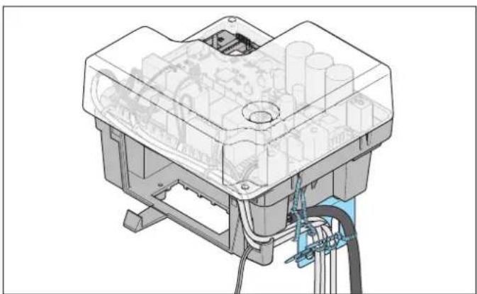
natural_image
Technical line drawing of a mechanical assembly with internal components and wiring (no text or symbols)Fig. Cable routing to the master gate operator
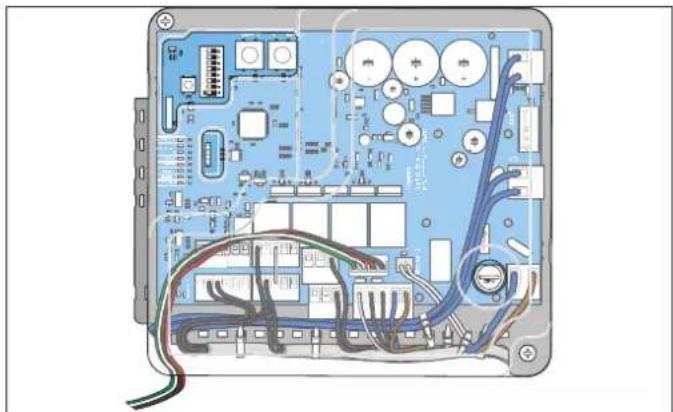
natural_image
Interior view of an electronic device showing circuit board, connectors, and wiring (no text or symbols visible)Fig. Cable routing in the master gate operator
All cables must be routed as shown above and then secured with cable binders. The shaft for the accumulator must remain accessible at all times. The cover must not rub against the cables.
- Feed the cables into the gate operator through the membrane bush and strip the insulation.
- Attach core end sleeves to the strands for flexible lines.
- Connect the individual wires to the specified terminals.
7.8 Connecting slave gate operator
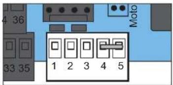
Fig. Connectingslave gate operator
1. Route the 5-wire connection cable from the master gate operator to the slave gate operator.
2. Remove the jumper fitted between terminals 4 and 5 on the master gate operator.
| Master gate operator terminal | Slave gate operator terminal | Function |
| 1 1 Motor cable | ||
| 2 2 Motor cable | ||
| 3 3 Hall sensor | ||
| 4 4 Emergency release | ||
| 5 5 Common (earth) | ||
7. Electrical connection and special functions
7.9 Connecting the warning light (WL)
Terminal Function
35 Warning light DC 22 V–34 V (max. 25 W)
36 Warning light earth

INFORMATION
- The warning light flashes during normal operation and at different sequences in the event of a fault.
The flash sequences can only be output if there is a suitable light bulb.
If light bulbs with slow reactions or, for instance, rotating lights are used, it might not be possible to correctly detect the flash sequence.
Overview of LED warning light (WL)
□ Off
- Operating voltage absent or power-saving mode activated
On
- Warning light is triggered/activated
- Gate movement is displayed, no other status indication possible
■ ■ ■ ■ ■ ■ ■ ■ ■
• Normal operation, flashes while gate is moving
- Programming mode activated
• Pre-warning time activated
- During reversing movement or soft reversal
7.10 Connecting photocells
To ensure correct function, photocells and safety devices must be correctly mounted, aligned and connected before initial operation. A 2-wire photocell is contained in the scope of delivery of the gate operator. Additional photocells can be purchased.
The control unit has 2 connections for photocells with 2- or 4-wire technology. Combinations are possible.
We recommend installing the photocell at a height of up to 300 mm. To protect property, it may be necessary to install an additional photocell, for example at a height of approx. 600 mm on the inside and outside.
Only photocells with 4-wire technology can be connected in series. For positions of the photocells on the gate system, see the application example in Chapter
"3.1 The operator and its mode of operation".

NOTE
- It may be necessary to install a second photocell inside and outside at an installation height of e.g. 600 mm. This makes it possible to also secure larger vehicles.

INFORMATION
- Only light-switching photocells with a floating relay contact and a voltage range of 12–22 V can be connected.
2-wire photocell
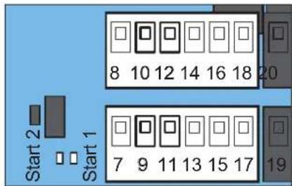
Fig. Connecting a 2-wire photocell
Photocell Terminal Function
| Exterior SAFETY 1 | 9 | Connections for photocell, any polarity |
| 11 | ||
| Interior SAFETY 2 | 10 | Connections for photocell, any polarity |
| 12 |
Terminals 7 and 13 or 8 and 14 are not connected when operating with 2-wire photocells.
4-wire photocell
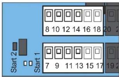
Fig. Connecting a 4-wire photocell
| Photocell Terminal | Function | |
| Exterior | 7 | Supply voltage +22 V |
| 9 | Signal relay contact | |
| SAFETY 1 | 11 | COM relay contact |
| 13 | Supply voltage GND | |
| Interior | 8 | Supply voltage +22 V |
| 10 | Signal relay contact | |
| SAFETY 2 | 12 | COM relay contact |
| 14 | Supply voltage earth | |
Overview of LED for warning light (SAFETY 1 and SAFETY 2)
□ Off
- No safety device connected in exterior or interior
On
• Safety device detected in exterior or interior
■ ■ ■ ■ ■ ■ ■ ■ ■ ■
- Safety device interrupted in exterior or interior, see Chapter "13. Troubleshooting"
7. Electrical connection and special functions
7.11 Connecting safety contact strip
To ensure correct functioning, photocells and safety devices must be correctly mounted and connected before initial operation.
Instead of an additional photocell for the inner side of the gate, an 8k2 strip can be connected as a safety device.
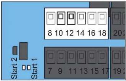
Fig. Connecting safety device
Terminal Function
| 10 | Safety device connections, 8k2 strip, any polarity |
| 12 |
7.12 Connecting an external EMERGENCY STOP
The control unit is prepared for the connection of an external EMERGENCY STOP signal.
DANGER

Danger due to electric current!
The gate operator is not disconnected from the power supply when an EMERGENCY STOP is triggered. Contact with live parts may result in electric current flowing through the body. Electric shock, burns or death may result.
▶ All work on electrical components must be carried out by a trained electrician.
The operator must be disconnected from the power supply before working on it.
▶ If an accumulator is connected, disconnect it from the control unit.
▶ Check that the operator is not live.
- Secure the operator against being switched back on.

INFORMATION
- When an EMERGENCY STOP is triggered, the motor relay control is interrupted and the operator is forced off. There is no all-pole disconnection of the voltage supply.
After the EMERGENCY STOP has been triggered, there is no gate movement. Not until EMERGENCY STOP has been released does the gate move in the gate OPEN direction.
This gate movement is performed in a soft run.
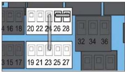
Fig. Connecting an external EMERGENCY STOP
- Remove the jumper fitted between terminals 26 and 28 (factory state).
- Connect the EMERGENCY STOP control element with a floating NC contact.
Terminal Function
| 26 | EMERGENCY STOP common (earth) |
| 28 | EMERGENCY STOP |
Overview of LED for Stop (yellow)

Off
- Stop or EMERGENCY STOP not activated

On
- Stop or EMERGENCY STOP activated
7.13 Connecting an electric lock (ELock)
The control unit is prepared for the connection of optional electric locks. Electric locks lock the gate leaves in closed state. Only SOMMER accessories can be connected.

NOTE
- Both connections simultaneously receive a pulse when the motor starts.
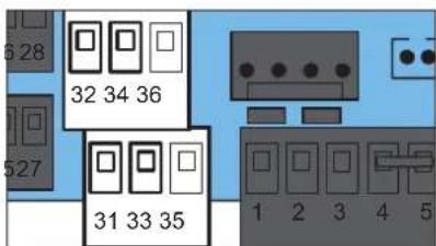
Fig. Connecting an electric lock
Gate Terminal Function
| Active leaf | 31 | Electric lock 1 +24 V |
| 32 | Electric lock 1, earth | |
| Inactive leaf | 33 | Electric lock 2, +24 V |
| 34 | Electric lock 2, earth |

INFORMATION
- The voltage for the electric lock is the direct and unregulated transformer voltage. The voltage can fluctuate between 22 V and 34 V, per electric lock 15 W.
7. Electrical connection and special functions
Overview of LED for ELock (green)
Off
• Electric lock is locked
On
• Electric lock is unlocked
7.14 Connecting control elements
□ Off
- Stop or EMERGENCY STOP not triggered
On
- Stop or EMERGENCY STOP triggered
WARNING

Danger of crushing and shearing!
As soon as the operator is supplied with power and the gate moves, there is a risk of crushing and shearing injuries for persons and animals in the gate movement area.
▶ Control devices may only be installed within view of the gate.
In particular when operating control elements, all danger zones must be visible during the entire gate operation.
▶ Always keep the moving gate in sight.
▶ Keep persons and animals clear of the range of movement of the gate.
▶ Never put your hand near the gate or near moving parts when the gate is moving.
▶ Do not drive through the gate until it has opened completely.
▶ Never stand in the opened gate.
The control unit is prepared for the connection of optional control elements.
Amongst others, the following control elements are available:
- Button
• Key switch
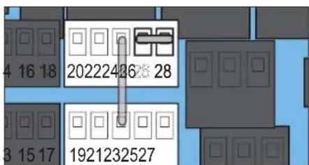
Fig. Control element connections
Terminal Connection Function in normal
| operation | ||
| 19 |  | Active and inactive leaf pulse button |
| 20 | ||
| 21 | 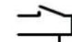 | Active leaf pulse button |
| 22 | ||
| 23 |  | Stops ongoing movements |
| 25 | Selectively Open | |
| 27 | Selectively Close | |
| 24 | Common (earth) |
NOTE
- Continuous contacts can block the proper function of the gate operator.
Only Pulse buttons may be connected. - The button on terminal 23 must be equipped with an NC contact.
When connecting a button on terminal 23, the jumper between terminal 23 and 24 (factory state) must be removed. - The input "Defined Open" can be configured as a timer input via SOMlink.
- The cable length for connecting a button must not exceed 25 m.
7.15 Multi-function relay (MUFU)
The control unit is fitted with a multi-function relay (MUFU). The multi-function relay can be used for various functions. In factory state, the multi-function relay outputs a pulse with a duration of 1 second every time the motor starts.
NOTE
- The contact of the multi-function relay is floating and may only be loaded with a maximum of AC 24 V/DC 1 A.
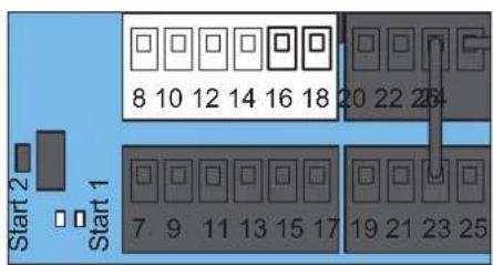
Fig. Multi-function relay connections
| Terminal | Terminal assignment | Function |
| 16 GND | 1 second at motor start | |
| 18 Signal | ||
7.16 Connecting mains power supply
The mains power cannot be connected until all other connections have been established.
See from Chapter "7.7 Preparing connections for the various functions". The connection to the accumulator is established last.
In the factory state, the master gate operator is equipped with a power cord with plug for tests and setting.
This power cord with plug is not suitable for continuous use inside or outside. The power cord with plug must be removed and a fixed mains power connection with a mains circuit breaker installed.

WARNING

Danger of crushing and shearing!
As soon as the operator is supplied with power and the gate moves, there is a risk of crushing and shearing injuries for persons and animals in the gate movement area.
The mains power and, if applicable, the accumulator, must be connected as the last step.
▶ All other connection work must be carried out with the mains voltage disconnected and the accumulator unplugged.
▶ All danger zones must be visible during the entire gate operation.
▶ Always keep the moving gate in sight.
▶ Keep persons and animals clear of the range of movement of the gate.
▶ Never put your hand near the gate when it is moving or near moving parts.
▶ Never stand in the opened gate.

NOTE
- Objects in the movement area of the gate may be jammed and damaged.
Objects must not be in the range of movement of the gate.
- The master gate operator is delivered with a connected power cord for adjustment work and provisional initial operation. This power cord must be removed after initial operation and replaced with a fixed mains connection with a mains circuit breaker. Otherwise, the operator will be damaged.
- Make sure that the power supply is interrupted.
- Remove the provisionally connected power cord (factory state).
- The new power cord with the exterior insulation must be routed under the transparent protective cover.
- Remove the exterior insulation over a length of about 3 cm.

DANGER! Danger due to electric current!
The gate operator is not disconnected from the power supply when an EMERGENCY STOP is triggered. Contact with live parts may result in electric current flowing through the body. Electric shock, burns or death may result.
▶ All work on electrical components must be carried out by a trained electrician.
▶ All wires and the exposed strands must be completely double-insulated up to the contact point.
- Strip the insulation from the brown (BR) and blue (BL) strands and attach core end sleeves firmly and professionally.
- Then pull a silicon hose over both strands and attach firmly and professionally.
- Fasten both wires with a cable binder in the area of the attached silicon hose.
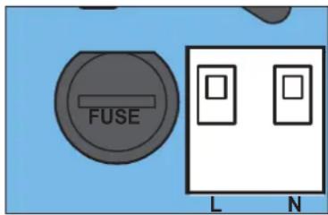
Fig. Terminals for mains power
- Connect the single wires to terminals L and N on the terminal block on the control unit board.

DANGER! Danger due to electric current!
Loosened strands can trigger a short circuit if they make contact with other conductive parts. Contact with live parts may result in electric current flowing through the body. Electric shock, burns, or death may result.
▶ All work on electrical components must be carried out by a trained electrician.
▶ Ensure that the strands are secured against unintentional loosening after connection to the mains power and cannot trigger a short circuit.
- Secure the strands against unintentional loosening of the mains power connection.
Overview of LED for status

Off
- Operating voltage absent, power-saving mode activated

On
- Hardware self-test

- Normal operation, flashes while gate is moving
- Programming mode activated
• Pre-warning time activated - During reversing movement or soft reversal
7.17 Installing and removing the accumulator
The accumulator can bridge approximately 5 cycles within 12 hours in the event of a power failure. The accumulator can only be recharged for a limited number of cycles. This depends on the use and settings. Mains voltage is required for initial operation of the operator. Only a trained electrician is permitted to install, test and replace the accumulator. See also Chapter "7.2 Disconnect the control unit from the mains voltage". Follow the instructions in the separate installation and operating manual for the accumulator.

DANGER

Danger due to electric current!
In order to insert the accumulator, the operator must be open and the electrical components must be readily accessible.
Contact with live parts may result in electric current flowing through the body. Electric shock, burns or death may result.
▶ All work on electrical components must be carried out by a trained electrician.
The operator must be disconnected from the power supply before working on it.
▶ If an accumulator is connected, disconnect it from the control unit.
▶ Check that the operator is not live.
- Secure the operator against being switched back on.

Danger of hazardous substances!
Improper storage, use or disposal of accumulators or batteries are dangerous for the health of humans and animals. Serious injury or death may result.
▶ Accumulators and batteries must be stored out of the reach of children and animals.
▶ Keep accumulators and batteries away from chemical, mechanical and thermal influences.
▶ Do not recharge old accumulators and batteries.
Components of the operator as well as old accumulators and batteries must not be disposed of with household waste. They must be disposed of properly.

WARNING

Danger of crushing and shearing!
As soon as the operator is supplied with power and the gate moves, there is a risk of crushing and shearing injuries for persons and animals in the gate movement area.
▶ Ensure that no accidental operation can occur after the accumulator is connected.
NOTE
- Objects in the movement area of the gate may be jammed and damaged. Objects must not be in the range of movement of the gate.
- Dispose of all components in accordance with local or national regulations to avoid environmental damage.

INFORMATION
- Operator components that have been taken out of service as well as old accumulators and batteries must not be disposed of with household waste. Dispose of components which are no longer in use, old accumulators and batteries properly. You must observe the local and national regulations here.
Installing the accumulator
- Plug the connection cable for the accumulator into the accumulator.
- Slide the accumulator completely into the rack for the accumulator until the locking tab engages.
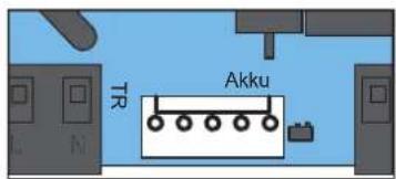
Fig. Connection for accumulator
- Route the connection cable for the accumulator and insert it into plug connector 15.
Removing the accumulator
The accumulator is removed in reverse order; see Chapter "7.17 Installing and removing the accumulator".
7.18 Information on SOMlink
SOMlink is a combination of an additional device and a web-based application. Since safety-relevant values can also be changed, SOMlink is only sold to qualified specialists. Qualified specialists only can use the SOMlink to change functions and settings on the gate operator. These include force and speed values as well as operating parameters and other convenient functions. All changes to settings via the SOMlink are logged. You can access a demo version of the WEB APP under: http://www.sommer-projects.de/gta_app/#home

INFORMATION

- All operator parameters are reset to the factory settings by a factory reset. All settings via SOMlink and WiFi-enabled device are also reset.
- The DIP switches can only be manually reset.
8.1 Important notes and information
In particular, observe the warnings below.

DANGER

Danger if not observed!
If warnings are not observed, serious injury or death may result.
▶ All warnings must be complied with.

WARNING

Crushing and shearing!
If the gate is not visible and the radio control is operated, crushing and shearing injuries to persons may occur.
In particular when operating control elements such as radio remote controls, all danger zones must be visible during the entire gate operation.
▶ Always keep the moving gate in sight.
▶ Keep persons and animals clear of the range of movement of the gate.
▶ Never put your hand near the gate or near moving parts when the gate is moving.
▶ Do not drive through the gate until it has opened completely.
▶ Store the handheld transmitter so that unauthorised or accidental operation, e.g., by children or animals, is impossible.
▶ Never stand in the opened gate.
8.2 Programming of end positions and operating forces
Pre-conditions
Before programming and connecting the operating voltage for the first time, the following conditions must be fulfilled:
- Fixed stops are present on the gate system and, if necessary, blocking elements are mounted and set in the operator arm, see Chapter “6.9 Adjusting the blocking elements”.
- The lines to the slave gate operator, if present, are fixed and connected, see Chapter "7.8 Connecting slave gate operator".
- The warning light is installed and connected, see Chapter "7.9 Connecting the warning light (WL)".
- The photocell is installed, aligned and connected, see Chapter "7.10 Connecting photocells".
- The basic configuration is set at DIP switches 8 and 7, see Chapter "7.6 Basic configuration".
- Optional safety devices, e.g. 8k2 strip, are installed and connected, see Chapter “7.11 Connecting safety contact strip”.
The definition of active leaf and inactive leaf can be found in Chapter "3.8 Definitions".
8.3 Basic configuration and preparations
DIP switches 7 and 8 are used to determine the positions for the master gate operator, slave gate operator and the closing sequences, see Chapter "3.8 Definitions".
All DIP switches are set to "OFF" in the factory settings.

NOTE
- Do not use a metal object to set the DIP switches, because this may damage the DIP switches or the circuit board.
Use a suitable tool to set the DIP switches, for example a flat, thin plastic object.
DIP switches ON OFF
8 Master gate operator is installed on the left gate leaf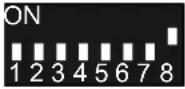 | Master gate operator is installed on the right gate leaf |
7 Master gate operator works as active leaf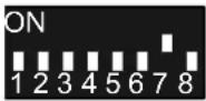 | Master gate operator works as inactive leaf |
Tab. DIP switches.8 and 7 for the functions of the master gate operator
The basic configuration is automatically read in after applying the operating voltage.

INFORMATION
- If the basic configuration is correctly set, the START 1 button controls the left gate and the START 2 button the right gate.
- 1-leaf gates only have an active leaf. Independent of the installation situation, DIP switch 7 must always be set to ON.
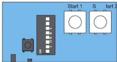
Fig. Displays and buttons for programming
The LEDs show various signals and states, see Chapter "7.5 Overview of the LEDs".
- At the master gate operator, release the operator from the gate arm using the emergency release lever.
- Move the gate leaf to the centre position.
- Relock the operator with the emergency release lever. It might be necessary to move the gate leaf a little in order to lock it.
- If present, move the gate leaf on the slave gate operator into the centre position and lock.
- Insert the power plug into a power outlet and/or switch on the power supply.
For a gate with 2 leaves, continue at the section "Programming a 2-leaf gate", for a gate with one leaf at the section "Programming a 1-leaf gate".
8.4 Programming a 1-leaf gate
After the operator has been connected to the voltage supply and the basic configuration has been correctly set, the first movement triggered by the operator is always gate OPEN. If this is not the case, the basic configuration must be checked and adjusted, see Chapter "7.6 Basic configuration".

INFORMATION
- 1-leaf gates only have an active leaf. Independent of the installation situation, DIP switch 7 must always be set to "ON", see Chapter "7.6 Basic configuration".
Programming the active leaf
- Press the START button for the active leaf briefly (<1 second).
⇒ Active leaf moves to the gate OPEN end position and switches off automatically.
⇒ The warning light and Status LED flash while the gate is moving.
⇒ The warning light gives a repeated sequence of two short flashes when the gate OPEN end position is reached.
- Press the START button for the active leaf briefly (<1 second) to save the end position.
⇒ The end position for gate OPEN is saved.
→ Active leaf moves to the gate CLOSE end position and switches off automatically.
⇒ The warning light and Status LED flash while the gate is moving.
⇒ The warning light gives a repeated sequence of two short flashes when the gate CLOSE end position is reached.
- Press the START button for the active leaf briefly (<1 second) to save the end position.
⇒ The end position for gate CLOSE is saved.
The operator starts its programming process automatically.
⇒ The force programming run starts automatically.
⇒ The active leaf moves automatically first to the gate OPEN end position and then to the gate CLOSE end position. As it does so, the required operating force is programmed.
⇒ The warning light and Status LED flash while the gate is moving.
⇒ The active leaf moves automatically to the gate OPEN end position.
- Press the START 1 and START 2 buttons simultaneously and briefly (1 second) until the LEDs for Open and Close flash at the same time.
⇒ The active leaf is programmed.
⇒ Operator is programmed and ready for use.
Optional
- Press the START button for the active leaf briefly (<1 second).
⇒ The active leaf moves automatically to the gate CLOSE end position.
⇒ The gate is closed.
8.5 Programming a 2-leaf gate
Programming the inactive leaf
In the case of a 2-leaf gate, the inactive leaf must be programmed first. Then the active leaf is programmed.

INFORMATION
- With a stop bar on a gate leaf, it is absolutely essential to programme the inactive leaf first.
- The inactive leaf must open first when the first button is pressed. If this is not the case, the basic configuration must be checked and adjusted, see Chapter “8.3 Basic configuration and preparations”.
- Press the START button for the inactive leaf briefly (<1 second).
⇒ Inactive leaf moves to the gate OPEN end position and switches off automatically.
⇒ The warning light and Status LED flash while the gate is moving.
⇒ The warning light gives a repeated sequence of two short flashes when the gate OPEN end position is reached.
- Press the START button for the inactive leaf briefly (<1 second) to save the end position.
⇒ The end position for gate OPEN is saved.
⇒ Inactive leaf moves to the gate CLOSE end position and switches off automatically.
⇒ The warning light and Status LED flash while the gate is moving.
⇒ The warning light gives a repeated sequence of two short flashes when the gate CLOSE end position is reached.
- Press the START button for the inactive leaf briefly (<1 second) to save the end position.
The end position for gate CLOSE is saved.
The operator starts its programming process automatically.
⇒ The force programming run starts automatically.
⇒ The inactive leaf moves automatically first to the gate OPEN end position and then to the gate CLOSE end position. As it does so, the required operating force is programmed.
⇒ The warning light and Status LED flash while the gate is moving.
⇒ The inactive leaf moves automatically to the gate OPEN end position.

INFORMATION
- If the inactive leaf is equipped with a stop bar and serves as a stop for the active leaf, the inactive leaf must be closed before programming the active leaf.
Optional
- Press the START button for the inactive leaf briefly (<1 second).
⇒ The inactive leaf moves automatically to the gate CLOSE end position.
⇒ The inactive leaf is closed.
Programming the active leaf
- Press the START button for the active leaf briefly (<1 second).
⇒ Active leaf moves to the gate OPEN end position and switches off automatically.
⇒ The warning light and Status LED flash while the gate is moving.
⇒ The warning light gives a repeated sequence of two short flashes when the gate OPEN end position is reached.
- Press the START button for the active leaf briefly (<1 second) to save the end position.
⇒ The end position for gate OPEN is saved.
⇒ Active leaf moves to the gate CLOSE end position and switches off automatically.
⇒ The warning light and Status LED flash while the gate is moving.
⇒ The warning light gives a repeated sequence of two short flashes when the gate CLOSE end position is reached.
- Press the START button for the active leaf briefly (<1 second) to save the end position.
⇒ The end position for gate CLOSE is saved.
The operator starts its programming process automatically.
⇒ The force programming run starts automatically.
⇒ The active leaf moves automatically first to the gate OPEN end position and then to the gate CLOSE end position. As it does so, the required operating force is programmed.
⇒ The warning light and Status LED flash while the gate is moving.
⇒ The active leaf moves automatically to the gate OPEN end position.
⇒ The active leaf is programmed.
⇒ Operator is programmed and ready for use.
Optional
- Press the START button for the active leaf briefly (<1 second).
⇒ The active leaf moves automatically to the gate CLOSE end position.
⇒ The gate is closed.
8.6 Obstacle detection event
The following section describes two obstacle detection events, “Obstacle detection event during programming of end positions” and “Detecting obstacles during the force programming run”.
Obstacle detection event during programming of end positions
If the gate runs into an obstacle during programming of the end positions, the operator stops. The warning light gives a repeated sequence of two short flashes.
- Press and hold the START 1 or START 2 button for the corresponding gate.
⇒ After 1 second, the operator triggers a brief movement in the last direction of travel.
-
Release the START 1 or START 2 button if the end position is reached after this brief movement. If an additional brief movement is required, press and hold the START 1 or START 2 button again until the brief movement is triggered.
-
The operator drives in the last direction of travel as long as the START 1 or START 2 button is pressed and held or until the forces become too great.
-
As soon as the end position is reached, release the START 1 or START 2 button.
-
Press the START 1 or START 2 button briefly (<1 second).
⇒ End position confirmed.
This procedure is identical for both directions of travel. After both end positions have been confirmed, the force programming run automatically starts.
Detecting obstacles during the force programming run
If the gate runs into an obstacle during the force programming run, the operator stops and reverses a short distance. At the same time, the warning light flashes.
- Briefly press the START 1 or START 2 button for the respective gate (<1 second).
⇒ The force programming run continues.
⇒ The gate leaf moves to the end position for the last direction selected.
- When the obstacle detection event has been remedied, the programming process for 1-leaf or 2-leaf gates must be completed, see Chapter "8.2 Programming of end positions and operating forces".
8.7 Setting the automatic closing function
When automatic closing is activated, the gate is opened by a pulse. The gate moves to the gate OPEN end position. The gate closes automatically after the hold open time.
To ensure correct functioning, photocells and safety devices must be correctly mounted, aligned and connected before initial operation, see Chapter
"7. Electrical connection and special functions".
Only photocells from SOMMER may be connected.

WARNING

Risk of injury during automatic closing! Automatically closing gates can injure people and animals in the movement area of the gate when the gate is closing. Serious injury or death may result.
It is essential to install a photocell before activating the automatic closing function.
In particular when automatic closing is activated, all danger zones must be visible during the entire gate operation.
▶ Always keep the moving gate in sight.
▶ Keep persons and animals clear of the range of movement of the gate.
▶ Never put your hand near the gate or near moving parts when the gate is moving.
▶ Do not drive through the gate until it has opened completely.
▶ Never stand in the opened gate.

NOTE
- If the gate is not in view and the operator is actuated, objects in the movement area of the gate may be jammed and damaged.
Objects must not be in the range of movement of the gate.

INFORMATION
- Connection of a photocell is a prerequisite for the automatic closing function.
- The automatic closing function will only start if a photocell is connected. Jumpers cannot be used. Operation with automatic closing function must comply with EN 12453:2017 (Plc). This is a legal requirement.
National regulations must be observed in non-European countries.
- The factory setting is fully automatic closing with a pre-set hold open time of 1 minute. The hold open time starts at the gate OPEN end position and from the position of a partially opened gate.
Activating the automatic closing function
- Close the gate.
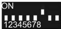
Fig.2
- Set DIP switch 6 to ON.
- The gate is opened by pressing the Pulse button on the transmitter. The gate movement cannot be stopped with the transmitter. The pre-set hold open time of the gate is 1 minute. Every new command within this minute restarts the hold open time.
⇒ The Status LED flashes.
Gate OPEN.
- The gate closes automatically after 1 minute.
⇒ The Status LED is off.
- The closing movement can be stopped by a command with the transmitter.
⇒ The Status LED flashes.
Gate opens completely – reversal of direction.
- The gate starts the closing process again after 1 minute.
⇒ The Status LED is off.
Gate CLOSE.
Shortening the hold open time
- Close command on handheld transmitter
• Signal pulse at terminal 27
- Drive-through of photocells
Activating pre-warning time of the warning light
The warning light flashes before the start of every gate movement.
- Close the gate.
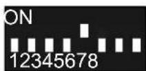
Fig.2
- Set DIP switch 5 to ON.
- If the Pulse button on the handheld transmitter is pressed:
⇒ The warning light flashes for 4 seconds.
⇒ The gate then opens.
8. Initial operation
8.8 Final commissioning work
The power cord installed at the time of delivery must be removed and a fixed mains power connection established at the latest after completing the adjustments.
Normal operation of the gate operator is only permitted with a fixed mains connection with a mains circuit breaker.
The mains power connection is described in Chapter "7.16 Connecting mains power supply".
8.9 Setting options for the DIP switches
You can select different functions via the DIP switches. The following table summarises the various setting options.
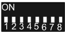
Fig. DIP switches

INFORMATION
- In the factory setting, all DIP switches are set to OFF.
- If a safety contact strip is connected at SAFETY 1 or SAFETY 2, the settings of DIP switches 1–3 have no effect.
The reaction with the safety contact strips is always EMERGENCY STOP with subsequent partial reversion.
8. Initial operation
Overview of setting options for the DIP switches
| DIP switches Function Effect | |||
| 1 |  OFF OFF | SAFETY 1, exterior photocell, CLOSE gate movement | SOFT STOP, full reversion |
| SOFT STOP, partial reversion | |||
| ON | |||
| 2 |  OFF OFF | SAFETY 2, interior photocell, OPEN gate move-OP, partial reversion | No reaction |
| ON SOFT ST | |||
| 3* |  OFF OFF | SAFETY 2, interior photo-cell, CLOSE gate move-ment | SOFT STOP, no reversion |
| SOFT STOP, partial reversion, full reversion** | |||
| ON | |||
| 4 |  OFF OFF | Power-saving mode | Activated |
| Deactivated | |||
| ON | |||
| 5 |  OFF OFF | Pre-warning timelight blinks for an additional | Warning light flashes during a gate movement |
| ON Warning | 4 seconds before the operator starts.The pre-warning time can be adjusted via SOMlink | ||
| 6 |  OFF OFF | Automatic closing, only with photocell | Normal mode |
| Automatic closing function | |||
| ON | |||
| 7 |  OFF OFF | Basic configuration | Master gate operator works as inactive leaf |
| Master gate operator works as active leaf | |||
| ON | |||
| 8 |  OFF OFF | Basic configuration | Master gate operator is installed on the right gate leaf |
| Master gate operator is installed on the left gate leaf | |||
| ON | |||

Factory setting
* The setting of DIP switch 3 only applies for photocells.
** Only with automatic closing function (DIP switch 6 ON).
9. Radio
9.1 Information on SOMloq2
The gate operator is equipped with a SOMloq2 radio system. The bidirectional data transmission between the transmitter and receiver allows a wide range of functions. Transmission is tap-proof and particularly reliable thanks to the special coding.
Separate antennas or other installations are not necessary. You can find more information in the separate SOMloq2 brochure.

9.2 Programming a handheld transmitter
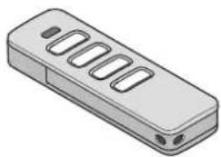
natural_image
Illustration of a remote control device with six slots and two ports (no text or symbols)Fig. Handheld transmitter
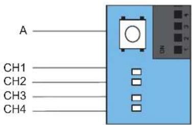
Fig. Radio button (A) and radio channels CH 1–4 on the master gate operator circuit board
Explanation of the LEDs for radio channels CH 1–4
| LED 1-leaf 2-leaf | ||
| CH 1 | - Open and close both gate leaves | |
| CH 2 | Open and close active leaf | Open and close active leaf |
| CH 3 | Open active leaf Open both gate leaves | |
| CH 4 | Close active leaf Close both gate leaves | |
These functions are assigned to the 4 radio channels in the factory state. In principle, the functions can be randomly assigned to the transmitter buttons.

INFORMATION
- CH 2 must be programmed in the receiver in a 1-leaf gate system.
-
If no button is detected as pressed on the handheld transmitter within 30 seconds, the LED for the selected radio channel (CH) goes out and programming mode is ended.
-
Select the desired radio channel (CH) by pressing the Radio button (A) on the control unit repeatedly.
⇒ LED for the selected radio channel lights up.
- Press the desired button on the handheld transmitter until the previously selected LED (CH 1, CH 2, CH 3 or CH 4) goes out.
⇒ LED goes out – programming is complete.
⇒ The transmitter has transferred the radio code to the radio receiver.
- Repeat the above steps to program additional transmitters.
If the memory capacity has been reached
A total of 40 handheld transmitter commands are available for all channels. If an attempt is made to program additional transmitters, the red LEDs of radio channels CH 1–4 blink. If more memory positions are needed, see chapter "9.3 Information on Memo".
9.3 Information on Memo
The memory capacity can be extended to 450 handheld transmitter commands using the optional Memo accessory part. When the Memo is plugged in, all available transmitters are transferred from the internal memory to the Memo and stored there. The Memo must remain plugged in on the control unit. No more transmitters are then stored in the internal memory. Stored transmitters cannot be transferred from the Memo back to the internal memory.
All radio channels, including the memory of the Memo, can be deleted, see Chapter "9.9 Deleting all radio channels in the receiver".
9. Radio
9.4 Overview of the time sequences
| 15 s | 20 s | 25 s | 30 s | |
| Delete transmitter button from the radio channel | Delete transmitter completely from the radio channel | Delete radio channel in the receiver | Delete all radio channels in the receiver | |
Fig. Time sequences for selecting the functions
The time sequences for the selection menu of the functions can be derived from the table. More exact descriptions are given in the following chapters.
9.5 Cancelling programming mode
- Press the Radio button (A) on the control unit repeatedly until the LED for a selected radio channel goes out, or do not make an entry for 30 seconds. ⇒ Programming mode is cancelled.
9.6 Deleting transmitter button from the radio channel
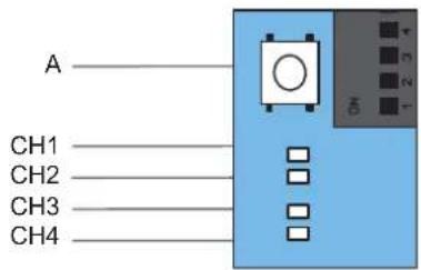
Fig. Radio button (A) and radio channels CH 1–4 on the master gate operator circuit board
- Press the Radio button (A) repeatedly to select the desired radio channel, and keep the Radio button (A) pressed for 15 seconds.
⇒ After 15 seconds, the LED of the selected radio channel flashes.
- Release the Radio button (A).
⇒ The radio receiver is now in deletion mode.
- Press the transmitter button for which the command is to be deleted in the radio channel.
⇒ The LED for the selected radio channel goes out.
⇒ The deletion procedure is ended.
- Repeat the process for additional buttons as required.
9.7 Deleting transmitter completely from the receiver
- Press and hold the Radio button (A) for 20 seconds. ⇒ The LED flashes after 15 seconds.
- After another 5 seconds, the flash sequence changes to blinking.
- Release the Radio button (A). ⇒ The radio receiver is now in deletion mode.
- Press any button on the transmitter that is to be deleted.
⇒ LED goes out.
⇒ The deletion procedure has been completed.
⇒ The transmitter is deleted from the radio receiver.
- Repeat the process for additional transmitters as required.
9. Radio
9.8 Deleting radio channel in the receiver
- Press the Radio button (A) repeatedly to select the desired radio channel, and keep the Radio button (A) pressed for 25 seconds.
⇒ After 15 seconds, the LED of the selected radio channel flashes.
⇒ After another 5 seconds, the flash sequence changes to blinking.
⇒ After another 5 seconds, the LED of the selected radio channel remains steady.
- Release the Radio button (A).
⇒ The deletion procedure is ended.
⇒ All programmed handheld transmitters on the selected radio channel are deleted from the radio receiver.
9.9 Deleting all radio channels in the receiver
With this function, all radio channels in the receiver are deleted. When the Memo accessory part is used, all data on the Memo are also deleted with this function.
⇒ Press and hold the Radio button for 30 seconds.
⇒ The LED flashes after 15 seconds.
⇒ After another 5 seconds, the flash sequence changes to blinking.
⇒ After another 5 seconds, the LED of the selected radio channel remains steady.
⇒ After another 5 seconds, all LEDs light up.
- Release the Radio button (A).
⇒ All LEDs are off after 5 seconds.
⇒ All programmed transmitters are deleted from the receiver.
→ Receiver is completely deleted, and this also applies for the Memo.
9.10 Programming an additional handheld transmitter by radio (HFL)
Prerequisites for programming by radio
A handheld transmitter must already be programmed on the radio receiver. The handheld transmitters used must be identical. This means, for example, that a Pearl can only be programmed on a Pearl and a Pearl Vibe on a Pearl Vibe.
The button assignment of handheld transmitter (A) that put the radio receiver into programming mode by radio is used for the new handheld transmitter (B) that is to be programmed. The already programmed handheld transmitter and the handheld transmitter that is to be programmed must be within the range of the radio receiver.
Example:
- On handheld transmitter (A), button 1 has been programmed to radio channel CH 1 and button 2 to radio channel CH 2.
⇒ The newly-programmed handheld transmitter (B) adopts the button assignment of transmitter (A): Button 1 to radio channel CH 1, button 2 to radio channel CH 2.
Restrictions
- This function is not possible with the Pearl twin hand-held transmitter.
- The targeted programming of a selected handheld transmitter button to a radio channel with HFL is not possible.
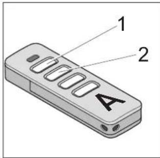
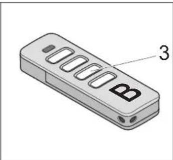
natural_image
Illustration of a remote control device with labeled ports (no text or symbols beyond the number 3)Fig. Handheld transmitter (A) and (B)
- Press buttons 1 and 2 of a programmed handheld transmitter (A) for 3–5 seconds until the LED on the handheld transmitter briefly lights up.
⇒ LEDs of the control unit flash.
- Release buttons 1 and 2 of handheld transmitter (A).
⇒ If no radio command is transmitted within another 30 seconds, the radio receiver switches over to normal mode.
- Press any button, e.g. (3) on the new handheld transmitter (B) to be programmed.
⇒ The LEDs remain steady.
⇒ The second handheld transmitter (B) has been programmed.
10.1 Checking the force setting and obstacle detection
After initial operation of the operator, the force setting of the operator must be checked with a force measurement device and an obstacle detection test must be performed. In particular, observe the warnings below.

WARNING

Danger of entrapment!
If the force setting is too high, persons in the movement area of the gate may be trapped and pulled along with the gate. Severe injuries or death may result.
The force setting is relevant to safety and must be very carefully checked and if necessary adjusted by a qualified specialist.

Danger of crushing and shearing!
If safety-related operator settings are made or changed, the gate can react unexpectedly. This may cause crushing or shearing injuries to persons and animals.
In particular if obstacle detection is performed, the gate can react unexpectedly.
▶ Always keep the moving gate in sight.
▶ Keep persons and animals clear of the range of movement of the gate.
▶ Never put your hand near the gate or near moving parts when the gate is moving.
▶ Do not drive through the gate until it has opened completely.
▶ Never stand in the opened gate.

Danger of crushing and shearing!
If the gate moves with persons or animals in the movement area, crushing and shearing injuries may be caused by the mechanism and safety edges of the gate.
In particular when obstacle detection is active, all danger zones must be visible during the entire gate operation.
▶ Always keep the moving gate in sight.
▶ Keep persons and animals clear of the range of movement of the gate.
▶ Never put your hand near the gate or near moving parts when the gate is moving.
▶ Do not drive through the gate until it has opened completely.
▶ Never stand in the opened gate.

NOTE
- Observe the national standards, guidelines and regulations for cut-off of the operating forces.
- The obstacle detection function must be tested once a month to prevent damage to the operator.

INFORMATION
- Reversing: The operator stops on contact with an obstacle and then moves a short distance in the opposite direction to release the obstacle.
- If a photocell is interrupted, the gate reverses in soft run.
- After installation of the operator, the person responsible for the installation of the operator must complete an EC Declaration of Conformity for the gate system in accordance with Machinery Directive 2006/42/EC and apply the CE mark and a type plate to the gate system. This also applies if the operator is retrofitted to a manually operated gate. All documents as well as the inspection book for the gate, the installation and operating manual and the handover protocol must be retained by the user.
Additional safety equipment such as photocells or safety contact strips must then be tested for correct functioning. The force settings must be tested with a force measurement device. Additional safety equipment such as photocells or safety contact strips must then be tested for correct functioning. If the gate hits an obstacle, it must reverse immediately. If this is not the case, a rest must be performed, see Chapter "11.7 Carrying out a reset".
The positions and the forces must be reprogrammed.
After successful testing of the force settings, the obstacle detection and the functions, the qualified specialist must attach the CE mark and the type plate to the gate system.
10.2 Handover of the gate system
You can find important information on handover to the user in Chapter "1.10 Qualifications of personnel", section "Instructing the user and handover of documents".
11.1 Important notes and information
In particular, observe the warnings below and the following Chapters “12. Maintenance and care” and “13. Troubleshooting”.

DANGER

Danger if not observed!
If warnings are not observed, serious injury or death may result.
▶ All warnings must be complied with.

Danger due to use of the operator with incorrect settings or when it is in need of repair!
If the operator is used despite incorrect settings or if it is in need of repair, severe injury or death may result.
The operator may only be used with the required settings and in the proper condition.
▶ You must have faults repaired professionally without delay.

WARNING

Danger due to irregular or omitted maintenance and testing!
Failure to test the operator regularly can cause damage or faults leading to serious or fatal injury to persons or animals.
▶ Test the operator monthly.
The gate operator must reverse if people or obstacles are present.
▶ Adjustments and settings may only be performed by a qualified specialist.
▶ After making adjustments to the operator, the operating forces must always be professionally tested.

Danger of crushing and shearing!
If the gate moves with persons or animals in the movement area, crushing and shearing injuries may be caused by the mechanism and safety edges of the gate.
▶ All danger zones must be visible during the entire gate operation.
▶ Always keep the moving gate in sight.
▶ Keep persons and animals clear of the range of movement of the gate.
▶ Never put your hand near the gate or near moving parts when the gate is moving.
▶ Do not drive through the gate until it has opened completely.
▶ Never stand in the opened gate.

NOTE
- If the operating forces of the gate are incorrectly adjusted, the operator may be damaged.
— The gate must be stable.
— It must not bend, rotate or twist when opening and closing.
— The gate must move easily along the entire travel path.
— Rectify faults or defects immediately, see Chapter "13. Troubleshooting".
- Defects must be repaired without delay by a qualified specialist.
- Objects in the movement area of the gate may be jammed and damaged.
Objects must not be in the range of movement of the gate.

INFORMATION
- Keep this Installation and Operating Manual accessible to all users at the place of use.
• Operation is only possible with an original SOMMER radio receiver attached. In addition, an external radio receiver can be connected.
11.2 Handover to the user
You can find important information on handover for the operator in Chapter "1.11 Information for the user".
11.3 Performing obstacle detection
The operator stops and reverses slightly if it encounters an obstacle. This prevents injury and damage to property. The gate will be partially or completely opened, depending on the setting.
The partial reversion is pre-set at the factory. Full reversion can be set via SOMlink and a WiFi-enabled device.
WARNING

Danger of entrapment!
If the force setting is too high, persons in the movement area of the gate may be trapped and culled along with the gate. Severe injuries or death may result.
The force setting is relevant to safety and must be carried out by a qualified specialist.
▶ You must proceed with extreme caution if you check and if necessary adjust the force setting.

Danger of crushing and shearing!
If the gate moves with persons or animals in the movement area, crushing and shearing injuries may be caused by the mechanism and safety edges of the gate.
In particular when obstacle detection is active, all danger zones must be visible during the entire gate operation.
▶ Always keep the moving gate in sight.
▶ Keep persons and animals clear of the range of movement of the gate.
▶ Never put your hand near the gate or near moving parts when the gate is moving.
▶ Do not drive through the gate until it has opened completely.
▶ Never stand in the opened gate.

INFORMATION
- Reversing: The operator stops on contact with an obstacle and then moves a short distance in the opposite direction to release the obstacle. In the automatic closing function, the gate opens completely.
- If a photocell is interrupted, the gate reverses in soft run.
- In the automatic closing function, the gate opens completely.
The following safety devices are installed to detect obstacles:
• photocell (object protection)
- safety contact strips (personal protection)
• obstacle detection of the operator (personal protection)
See also Chapter "12. Maintenance and care".
The gate must always reverse if it hits a suitable hard obstacle with an edge length of at least 10 cm before reaching the end position. Obstacle detection must be performed once a month by the user.
- Open the gate with the operator.
- Additional safety equipment such as photocells or safety contact strips must be tested for perfect functioning. To do this, briefly interrupt the photocells with suitable materials.
- Close the gate.
⇒ If the gate hits an obstacle, it must reverse immediately.
- If the gate does not reverse, a qualified specialist must be consulted.
11.4 Setting power-saving mode
To save energy, the operator control unit switches to power-saving mode after a specified period.
Connected accessories, e.g. safety contact strips or photocells, are then deactivated. With the next command via the buttons or the radio control system, the operator and the accessories are reactivated.
DIP switches ON OFF
4 Power-saving
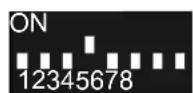
mode deactivated
Power-saving mode activated (factory state)

INFORMATION
- If power-saving mode has been activated, the factory-set time before switching to power-saving mode is about 1 minute.
DIP switch 4 must be set to "ON" to deactivate power-saving mode.
11.5 In the event of a power failure
The programmed force and position values are retained in the event of a power failure. The first movement of the operator after the power supply returns is always gate OPEN.
When voltage returns after a power failure, the gate operator reacts as follows when a button is pressed:
- In the case of a 1-leaf gate system, the master gate operator starts up.
- With a 2-leaf gate system, the active leaf opens completely and then the inactive leaf opens.
• The warning light continues to blink after opening. - If the button on the handheld transmitter is pressed again, the operator once again tries to drive in gate OPEN direction.
- When the button on the handheld transmitter is pressed again, the gate system closes.
• The warning light switches off.
Also observe the instructions for emergency release in Chapter "11.6 Function of the emergency release".
Operation during a power failure is only possible with an accumulator installed. A fully-charged accumulator has energy for about 5 cycles. The number is dependent on the mass and mobility of the gate leaf, the ambient temperature as well as the age of the accumulator.
11.6 Function of the emergency release
In the event of a fault, the gate can be opened using a mechanical emergency release.

WARNING

Danger of crushing and shearing!
If the gate is opened with the emergency release lever, the gate can move unexpectedly. Crushing and shearing injuries may be caused by the mechanism and safety edges of the gate if the gate moves with persons or animals in the movement area.
The emergency release lever must not be used during heavy storms or bad weather.
- Secure the gate against unexpected movement before operating the emergency release lever.
▶ Keep persons and animals clear of the range of movement of the gate.

NOTE
- The emergency release is only suitable for opening or closing the gate in an emergency, e.g. in the event of a power failure.
The emergency release is not suitable for regularly opening or closing the gate. This could cause damage to the operator or gate.

INFORMATION
- The gate can be unlocked in any gate position. It might be necessary to move the gate leaf a little in order to unlock it.
Unlocking the operator
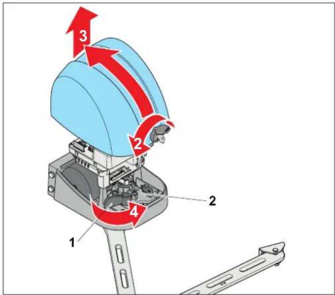
Fig. Unlocking the operator – emergency release lever (1), motor plate (2)
- Open the dust cap.
Insert the key into the gate operator cover and turn it 90° to the left. - Tilt the cover slightly towards the rear and remove it in upward direction.
- Turn the emergency release lever (1) at the front stop.
⇒ LED for Stop lights up green.
⇒ The motor plate (2) moves back.
⇒ The operator is released from the gate arm.
⇒ The gate leaf can now be moved by hand.
- Attach and lock the cover in reverse order.

INFORMATION
• After unlocking, the operator must be locked again.
After the emergency release lever has been actuated, the position of the gate leaves is unknown for the control unit.
When a button on the handheld transmitter or other control elements is pressed, the gate operator reacts in the same way as after a power failure, see Chapter "11.5 In the event of a power failure".
11. Operation
Locking the operator
For normal operation, the operator must be locked again.
Proceed in reverse order to lock the operator.
If both operators of 2-leaf gates were unlocked, both have to be relocked.
See Chapter "11.6 Function of the emergency release", section "Unlocking the operator".

INFORMATION
- The gate leaf has to be moved slightly when the emergency release lever is pressed back.
11.7 Carrying out a reset
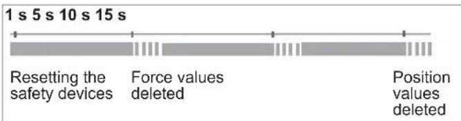
Fig. Time sequence for reset
During a reset, the warning light and the LED for the warning light flash in the pattern shown.
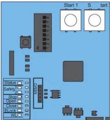
Fig. LEDs and START 1 and START 2 buttons

INFORMATION
- A SOMlink and a WiFi-enabled device are required to reset all parameters to the factory setting.
Resetting the safety devices
- Press the START 1 and START 2 buttons simultaneously for 1 second until the green LED for Status lights up.
⇒ Safety devices are deleted.
Deleting the force values
- Press the START 1 and START 2 buttons simultaneously for 5 seconds until the green LED for Status lights up.
⇒ Force values are deleted.
Deleting the position values
- Press the START 1 and START 2 buttons simultaneously for 15 seconds until the green LED for Status lights up.
⇒ Position values are deleted.
11.8 Jog mode in the event of faults
If a photocell is malfunctioning or defective the control unit can become blocked. This means that the gate system no longer opens or closes at the press of a button. The gate leaves must be moved in "Jog mode" operating mode.
To do so, execute the "Selectively open" or "Selectively close" command. This is done by pressing and holding the respective button on external control elements such as the key switch or on the handheld transmitter.
When the cover is open, the command can also be given by pressing the START 1 or START 2 buttons.
Jog mode is not suitable for normal operation.
Faults must be professionally remedied without delay.

WARNING

Danger of crushing and shearing!
If the gate moves with persons or animals in the movement area, crushing and shearing injuries may be caused by the mechanism and safety edges of the gate.
Jog mode may only be executed when you are in the immediately vicinity of the gate.
▶ All danger zones must be visible during the entire gate operation.
▶ Always keep the moving gate in sight.
▶ Keep persons and animals clear of the range of movement of the gate.
▶ Never put your hand near the gate when it is moving or near moving parts.
▶ Do not drive through the gate until it has opened completely.
▶ You must have faults or defects repaired professionally without delay.
11. Operation

NOTE
- Jog mode is not suitable for normal operation. Faults and defects must be remedied professionally and without delay by a qualified specialist to prevent further damage or defects.
- Check whether there is an obstacle in the range of the gate movement. If there is, remove the obstacle.
- If there is no obstacle in the range of the gate movement, press the "Selectively open" or "Selectively close" button and hold it pressed until the end position has been reached.

INFORMATION
• To prevent unintentional operation, the corresponding button must first be held down for 10 seconds for this function. Only then does the operator start.
2.1 On the control unit:
Press the START 1 or START 2 button on the circuit board.
Or:
2.2 On the handheld transmitter:
Press the desired button on the handheld transmitter.
The gate moves as long as the button on the hand-held transmitter is pressed.
⇒ The gate moves as long as the buttons are held pressed.
3. To ensure normal operation again, the fault or defect must be remedied professionally by a qualified specialist.
11.9 Operating modes of gate movement
In the following description of the gate movement, it is assumed that buttons 1–4 on the handheld transmitter have been assigned to radio channels CH 1–4. With 2-leaf gates, the movements of the two gate leaves start with a time delay.

WARNING

Danger of injury during gate operation! Gates can injure people or animals in the movement area of the gate when the gate is closing. This may cause crushing or shearing injuries.

In particular when operating control elements, all danger zones must be visible during the entire gate operation.
▶ Keep persons and animals clear of the range of movement of the gate.
▶ Always keep the moving gate in sight.
▶ Never put your hand near the gate or near moving parts when the gate is moving.
▶ Do not drive through the gate until it has opened completely.
▶ Never stand in the opened gate.

INFORMATION
- Reversing: The operator stops when it hits an obstacle. The gate then moves slightly in the opposite direction to release the obstacle. In the automatic closing function, the gate opens completely.
- In the event of interruption of the photocell, the run-on time is longer than when the gate hits an obstacle.
The following safety devices are installed to detect obstacles:
• obstacle detection of operator (personal protection)
• safety contact strips (personal protection)
- photocell (object protection)
Overview of gate movements
The figures show the sequence of movements of the gate leaves. The prerequisite for button assignment is that the gate system is programmed, see Chapter "8.2 Programming of end positions and operating forces".
The button assignment of the handheld transmitter corresponds to the basic factory setting.
11. Operation
2-leaf 1-leaf
Open and close both gate leaves
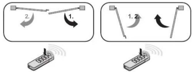
Pulse sequence of button 1 on the handheld transmitter
Open and close active leaf
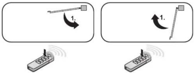
Pulse sequence of button 1 on the handheld transmitter, button 2 identical
Selectively open and close active leaf
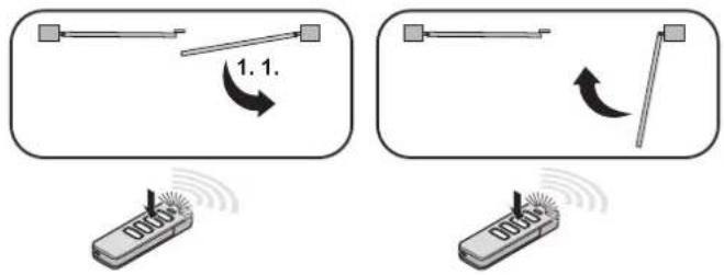
Pulse sequence of button 2 on the handheld transmitter
Open and close active leaf
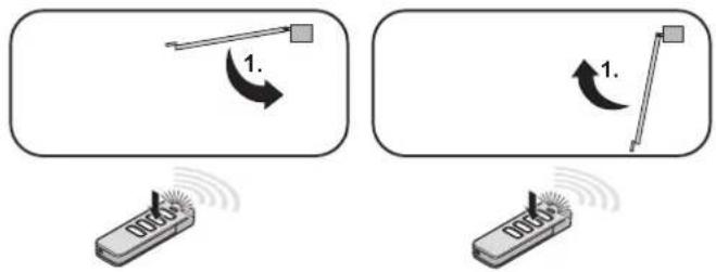
Pulse sequence of button 2 on the handheld transmitter, button 1 identical
Selectively open active and inactive leaf
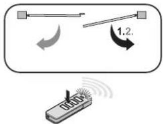
Pulse sequence of button 3 on the handheld transmitter
Selectively open active leaf
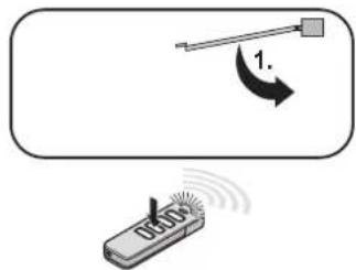
Pulse sequence of button 3 on the handheld transmitter, without function if gate OPEN
Selectively close active and inactive leaf
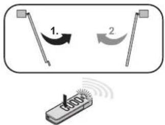
Pulse sequence of button 4 on the handheld transmitter
Selectively close active leaf
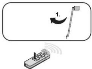
Pulse sequence of button 4 on the handheld transmitter, without function if gate CLOSE
12.1 Important notes and information
Service the operator regularly as directed below. This ensures safe operation of your operator and a long service life. If you have a question on maintenance and care, contact a qualified specialist. In particular, observe the warnings below.

DANGER

Danger if not observed!
If warnings are not observed, serious injury or death may result.
▶ All warnings must be complied with.

Danger due to electric current!
Contact with live parts may result in electric current flowing through the body.
Electric shock, burns or death may result.
▶ All work on electrical components must be carried out by a trained electrician.
The operator must be disconnected from the power supply before working on it.
▶ If an accumulator is connected, disconnect it from the control unit.
▶ Check that the operator is not live.
- Secure the operator against being switched back on.

WARNING

Danger of crushing and shearing!
If the gate moves with persons or animals in the movement area, crushing and shearing injuries may be caused by the mechanism and safety edges of the gate.
▶ All danger zones must be visible during the entire gate operation.
▶ Always keep the moving gate in sight.
▶ Keep persons and animals clear of the range of movement of the gate.
▶ Never put your hand near the gate when it is moving or near moving parts.
▶ Do not drive through the gate until it has opened completely.
▶ Never stand in the opened gate.

Danger due to hot parts!
After frequent operation, the motor and control unit may become hot. If the cover is removed and hot parts are touched, they may cause burns.
▶ Allow the operator to cool down before removing the cover.

NOTE
- Powerful spray water will damage the operator unit and hinged bracket.
Protect the operator unit and the hinged bracket from powerful spray water, e.g. from a garden hose.
- The use of unsuitable cleaning agents may damage the surface of the operator. No metal objects may be used.
Clean the operator with a damp, lint-free cloth only.
12.2 Maintenance schedule
| How often? | What? Who? | How? |
| Once a month | ·Check all safety devices | ·qualified specialist, for correct functioning |
| ·Test obstacle detection | ·qualified specialist, see Chapter “10.1 Checking the force setting and obstacle detection” | |
| ·Check that the gate runs smoothly | ·user, see Chapter “6.2 Preparing for installation” | |
| ·Test the emergency release | ·user, see Chapter “11.6 Function of the emergency release” | |
| Once a year | ·Test the gate and all moving parts | ·qualified specialist, as directed by the manufacturer |
| ·Test the gate hinges | ·user, check for smooth running, lubricate if necessary | |
| ·Check the mounting bolts of the operator | ·qualified specialist, check that bolts are tight and tighten if necessary | |
| As needed | ·Clean cover and hinged brackets | ·user, with a damp, lint-free cloth |
| ·Clean the photocell | ·user, see Chapter “12.3 Care”, section "Cleaning the photocell" |
12. Maintenance and care
12.3 Care
Cleaning the gate operator
- Disconnect the operator from the power supply.
Check that the operator is not live and secure it against being switched on again. - If an accumulator has been installed, operate the emergency release, see Chapter "11.6 Function of the emergency release".
- Secure the movement area of the gate.
- Remove dirt from the cover and the hinged bracket with a damp and lint-free cloth.

NOTE
- Do not use metal objects to clean the inside of the control unit.
- Reconnect the power supply. To do so, switch on the main switch or the fuse.
If necessary, lock the emergency release again, see Chapter "11.6 Function of the emergency release", section "Locking the operator."
Cleaning the photocell
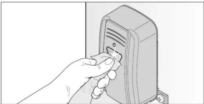
natural_image
Hand inserting a small electronic device into a rectangular device (no text or symbols visible)Fig.1

NOTE
- Do not change the position of the photocell when cleaning it.
-
Clean the housing and reflectors of the photocell with a damp, lint-free cloth.
-
Check the mounting of the photocells.
13.1 Important notes and information
In particular, observe the warnings below.

DANGER

Danger if not observed!
If warnings are not observed, serious injury or death may result.
▶ All warnings must be complied with.

Danger due to electric current!
Contact with live parts may result in electric current flowing through the body.
Electric shock, burns, or death may result.
▶ All work on electrical components must be carried out by a trained electrician.
The operator must be disconnected from the power supply before working on it.
▶ If an accumulator is connected, disconnect it from the control unit.
▶ Check that the operator is not live.
- Secure the operator against being switched back on.

Danger due to use of the operator with incorrect settings or when it is in need of repair!
If the operator is used despite incorrect settings or if it is in need of repair, severe injury or death may result.
The operator may only be used with the required settings and in the proper condition.
▶ You must have faults repaired professionally without delay.

WARNING

Danger of injury to due to trapping of clothing or long hair!
Loose clothing or long hair may be trapped by moving parts of the gate.
▶ Keep clear of the moving gate.
▶ Always wear tight-fitting clothing.
▶ Wear a hairnet if you have long hair.

Danger of crushing and shearing!
If operator settings are made or changed, the gate can react unexpectedly. This may cause crushing or shearing injuries to persons and animals.
If settings or changes are made to the operator:
▶ Keep persons and animals clear of the range of movement of the gate.
- Secure the movement area of the gate leaves.
▶ You must be able to see the movement area of the gate leaves.
▶ Never put your hand near the gate when it is moving or near moving parts.
▶ Never stand in the opened gate.
The force values must be checked by a qualified specialist. If necessary, the force values must be reset and reprogrammed.

Danger due to hot parts!
After frequent operation, the motor and control unit may become hot. If the cover is removed and hot parts are touched, they may cause burns.
▶ Allow the operator to cool down before removing the cover.

NOTE
- If the gate is not in view and the radio remote control is actuated, objects in the movement area of the gate may be jammed and damaged.
Objects must not be in the range of movement of the gate.
13.2 Troubleshooting
The following guide to troubleshooting lists potential problems and their causes and information on correcting them. In some cases, other chapters and sections with a more detailed description are referenced. You will be prompted to call a qualified specialist if this is required.
Work on the electrical system and live parts must be performed by a trained electrician.
- Disconnect the operator from the mains power.
If an accumulator is used, it must also be disconnected, see Chapter "7.17 Installing and removing the accumulator".
- Check that the operator is disconnected from the power supply and secure it against being switched on again.
- After working on the operator, first connect the accumulator, then the voltage supply. Check that the voltage supply is connected.
13.3 Time sequences of LEDs for accessories in normal mode and in the case of faults
The flash sequences show information on malfunctions for technicians, end customers and telephone support.
| LED Flash sequence Cause | ||
| Status(green) | □ Off | ·Operating voltage absent or power-saving mode activated |
| ■ On | ·Hardware self-test | |
| ■ ■ ■ ■ ■ ■ ■ ■ ■ ■ | ·Normal operation, flashes while gate is moving·Programming mode activated·Pre-warning time activated·During reversing movement or soft reversal | |
| ■■ ■■ ■■ ■■ ■■ ■■ ■■ | ·Waiting for confirmation during the gate CLOSE position programming run | |
| ■■■ ■■■ ■■■ ■■■ ■■■ | ·Fault display·Safety device not OK before movement·Safety device interrupted during movement·Interrupted safety device, see chapter “11.8 Jog mode in the event of faults” | |
| ■■■■ ■■■■ ■■■■ ■■■■ | ·Display of a fault, see Chapter “13.4 Troubleshooting table” | |
| ■ ■ ■ ■ ■ ■ ■ ■ ■ ■ | ·Service required (e.g. pre-set limit value reached) | |
| SAFETY 1(yellow) | □ Off | ·No safety device connected in exterior |
| ■ On | ·Safety device detected in exterior | |
| ■ ■ ■ ■ ■ ■ ■ ■ ■ ■ | ·Safety device in exterior interrupted/fault | |
| SAFETY 2(yellow) | □ Off | ·No safety device connected in interior |
| ■ On | ·Safety device detected in interior | |
| ■ ■ ■ ■ ■ ■ ■ ■ ■ ■ | ·Safety device in interior interrupted/fault | |
| Stop(green) | □ Off | ·EMERGENCY STOP not actuated |
| ■ On | ·EMERGENCY STOP actuated | |
| Open(green) | □ Off | ·Operator is deactivated |
| ■ On | ·Operator running in gate OPEN direction | |
| Close(green) | □ Off | ·Operator is deactivated |
| ■ On | ·Operator running in gate CLOSE direction | |
| ELock(yellow) | □ Off | ·Electric lock is locked |
| ■ On | ·Electric lock is unlocked | |
| Warninglight, WL(yellow) | □ Off | ·Operating voltage absent, power-saving mode activated |
| ■ On | ·Warning light is triggered/activated·Gate movement is displayed, no other status indication possible | |
| ■ ■ ■ ■ ■ ■ ■ ■ ■ ■ | ·Normal operation, flashes while gate is moving·Programming mode activated·Pre-warning time activated·During reversing movement or soft reversal | |
| ■■ ■■ ■■ ■■ ■■ ■■ ■■ | ·Waiting for confirmation during the programming run for gate CLOSE or gate OPEN position | |
| ■■■ ■■■ ■■■ ■■■ ■■■ | ·Fault display. Display via warning light for additional 10 seconds after a gate movement·Safety device not OK before movement·Safety device interrupted during movement·Interrupted safety device, see chapter “11.8 Jog mode in the event of faults” | |
| ■■■■ ■■■■ ■■■■ ■■■■ | ·See Chapter “13.4 Troubleshooting table” | |
| ■ ■ ■ ■ ■ ■ ■ ■ ■ ■ | ·Service required (e.g. pre-set limit value reached) | |
| Multi-functionrelay, MUFU(yellow) | □ Off | ·Multi-function relay is deactivated |
| ■ On | ·Multi-function relay is activated | |
A connection diagram can be found in Chapter "16. Setting options for the DIP switches and connection diagram for twist AM".
13. Troubleshooting
13.4 Troubleshooting table
In normal mode
The flash sequence of the LEDs for the warning light show information on malfunctions for technicians, end customers and telephone support.
| Flash sequences Possible cause Corrective action | ||
| NormalWarning light or LED for Light | Programming mode activatedPre-warning time activatedClearing time activated | none, for information |
| Interruption of a safety device during the movement | Remove obstacle | |
| Function for HFL activated | ||
Flash sequences in the case of faults
| Flash sequences Possible cause Corrective action | ||
| RequirementOperator expects a command | ·Waiting for a confirmation during the position programming run of gate OPEN and gate CLOSE position | ·Confirmation of position programming run |
| AlarmA process has triggered a fault | ·Photocell/safety device not OK before movement, SAFETY 1 or SAFETY 2 also blinks | ·Check photocell, realign if necessary·If necessary, have parts replaced by a qualified specialist |
| ·Safety device not OK · Have it checked by a qualified specialist | ||
| ServiceA process has triggered a fault | ·Service required (service days, service cycles have been reached) | ·Have the service performed by a qualified specialist |
| ·Motor temperature is too high (overheating) | ·Allow motor to cool | |
| FaultOperator or parts of the operator faulty | ·Significant system fault | ·Have it checked by a qualified specialist·If necessary, have operator or components replaced by a qualified specialist |
13. Troubleshooting
| Problem Possible cause Test/check Remedy | |||
| Gate does not open | Power failure • Check the fuse | • Replace the fuse | |
| • Emergency stop operated • Release emergency stop | |||
| • Emergency release activated • Lock emergency release | |||
| • If necessary, have accumulator checked | • Charge accumulator/have it replaced | ||
| Safety contact strip in interior tripped or defective display LED for SAFETY 2 | • Obstacle in gate travel path • Remove obstacle | ||
| • Safety contact strip defective (rubber profile deformed, contact fault) | • Have safety contact strip checked and replaced if necessary | ||
| Photocell in interior tripped or defective display LED for SAFETY 2 | • Obstacle in gate travel path • Remove obstacle | ||
| • Dirty lens • Clean the photocell, see Chapter “12.3 Care” | |||
| • Check if alignment is correct • Align photocell | |||
| • Contact fault • Have connections checked | |||
| • Interrupted photocell • See Chapter “11.8 Jog mode in the event of faults” | |||
| Radio signal transmission faulty | • Transmitter battery weak • Replace transmitter battery | ||
| • Range too short | • Reduce distance | ||
| • Transmitter defective | • Have transmitter replaced | ||
| Electric lock remains locked | • Check electric lock | • Check/have electric lock and connections replaced | |
| Gate does not close | Power failure | • Check the fuse | • Replace the fuse |
| • Emergency stop operated • Release emergency stop | |||
| • Emergency release activated • Lock emergency release | |||
| • If necessary, have accumulator checked | • Charge accumulator/have it replaced | ||
| Safety contact strip in exterior tripped or defective display LED for SAFETY 1 | • Obstacle in gate travel path • Remove obstacle | ||
| • Safety contact strip defective (rubber profile deformed, contact fault) | • Have safety contact strip checked and replaced if necessary | ||
| Photocell in exterior tripped or defective display LED for SAFETY 1 | • Obstacle in gate travel path • Remove obstacle | ||
| • Dirty lens • Clean the photocell, see Chapter “12.3 Care” | |||
| • Check if alignment is correct • Align photocell | |||
| • Contact fault • Have connections checked | |||
| • Interrupted photocell • See Chapter “11.8 Jog mode in the event of faults” | |||
| Radio signal transmission | • Transmitter battery weak • Replace transmitter battery | ||
| • Check range | • Reduce distance | ||
| • Transmitter defective | • Replace transmitter | ||
13. Troubleshooting
| Problem Possible cause Test/check Remedy | |||
| Gate operation interrupted | Power failure • Check the | fuse • Replace the fuse | |
| • Emergency stop operated • Release emergency stop | |||
| • Emergency release activated • Lock emergency release | |||
| • If necessary, have accumulator checked | • Charge accumulator/have it replaced | ||
| Renewed pulse by command device | • Unintended operation • Secure command device, e.g. handheld transmitter | ||
| • Faulty contact • Have connections checked | |||
| Obstacle detection detects an obstacle | • EMERGENCY STOP with reversion, warning light flashes three times | • Remove obstacle• If gate is not running smoothly, have it repaired• Observe wind load | |
| Safety contact strip detects an obstacle | • EMERGENCY STOP with reversion | • Remove object from the gate travel path• Check the function of the safety device | |
| Photocell detects an obstacle | • Soft stop with reversion • Remove object from the gate travel path• Check the function of the safety device• Have defective photocell replaced• Interrupted safety device, see chapter “11.8 Jog mode in the event of faults” | ||
14. Taking out of operation, storage and disposal
14.1 Important notes and information
Disassembly of the operator may only be performed by a qualified specialist. In particular, observe the warnings below.

DANGER

Danger if not observed!
If warnings are not observed, serious injury or death may result.
▶ All warnings must be complied with.

Danger due to electric current!
Contact with live parts may result in electric current flowing through the body.
Electric shock, burns, or death may result.
▶ All disassembly work on electrical components must be carried out by a trained electrician.
The operator must be disconnected from the power supply before disassembling it.
▶ If an accumulator is connected, disconnect it from the control unit.
▶ Check that the operator is not live.
▶ Secure the operator against being switched back on.

WARNING

Danger of tripping and falling!
Unsafely positioned parts such as packaging, operator parts or tools may cause trips or falls.
- Keep the disassembly area free of unnecessary items.
Place all parts where no-one is likely to trip or fall over them.
The general workplace guidelines must be observed.

Danger due to hot parts!
After frequent operation, the motor and control unit may become hot. If the cover is removed and hot parts are touched, they may cause burns.
▶ Allow the operator to cool down before removing the cover.

Risk of eye injury!
Chips flying when drilling may cause serious injuries to eyes and hands.
▶ Wear safety glasses when drilling.


Risk of injury to feet!
Falling parts can cause foot injuries.
▶ Wear safety shoes.

CAUTION

Risk of injury to hands!
Rough metal parts may cause abrasions and cuts when picked up or touched.
▶ You must wear your personal safety gloves when working with rough metal parts.

NOTE
- If there is an accumulator in the master gate operator, it must be removed by a qualified electrician. See Chapter "7.17 Installing and removing the accumulator".
14.2 Taking out of operation and disassembly
The operator and its accessories must be disconnected from electrical power when taking them out of operation or during disassembly.
- Disconnect the control unit from the mains voltage or disconnect the main switch or the fuse for the circuit that supplies the operator with voltage. See Chapter "7.2 Disconnect the control unit from the mains voltage".
- If an accumulator was used, disconnect it; see Chapter "7.17 Installing and removing the accumulator".
- Disassembly is carried out in reverse order of installation.
14.3 Storage

NOTE
- Improper storage may damage the operator. The operator must be stored in closed and dry rooms.
Store the packaging units as follows:
- in enclosed, dry rooms so that they are protected from moisture
- at a storage temperature from -25^ to +65^
- secure to prevent falling
- leave room for unhindered passage
14. Taking out of operation, storage and disposal
14.4 Disposal of waste
Observe the instructions for disposal of packaging, components, batteries and, if applicable, the accumulator.

DANGER

Danger of hazardous substances!
Improper storage, use or disposal of accumulators, batteries or operator components are dangerous for the health of humans and animals. Serious injury or death may result.
▶ Accumulators and batteries must be stored out of the reach of children and animals.
▶ Keep accumulators and batteries away from chemical, mechanical and thermal influences.
▶ Do not recharge old accumulators and batteries.
Components of the operator as well as old accumulators and batteries must not be disposed of with household waste. They must be disposed of properly.

NOTE
- Dispose of all components in accordance with local or national regulations to avoid environmental damage.

INFORMATION
- Operator components that have been taken out of service as well as old accumulators and batteries must not be disposed of with household waste. Dispose of components which are no longer in use, old accumulators and batteries properly. You must observe the local and national regulations here.
15. Short instructions for installation
The short instructions do not replace the installation and operating manual.
Read this Installation and Operating Manual carefully and, most importantly, observe all safety instructions and warnings. This will ensure that you can install the product safely and optimally.
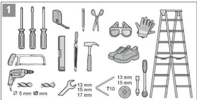
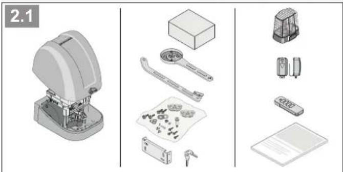
natural_image
Exploded view diagram of a mechanical device showing exploded view, assembled parts, and packaging (no text or labels)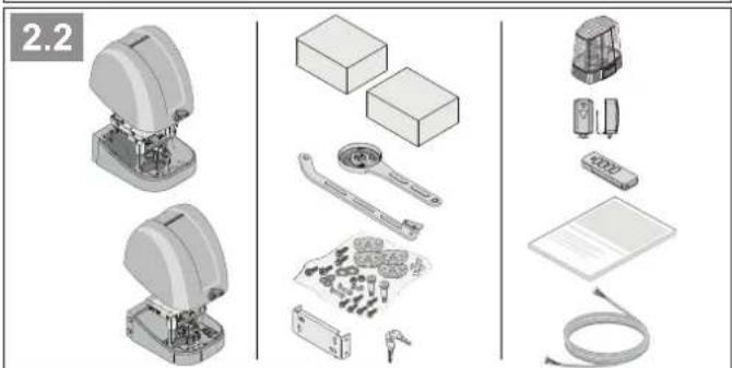
natural_image
Exploded view diagram of industrial robotic devices including motors, enclosures, and sensors (no text or labels)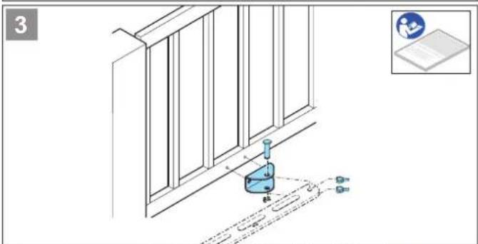
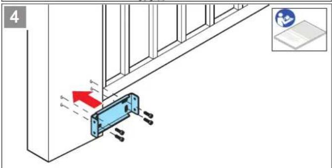
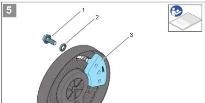
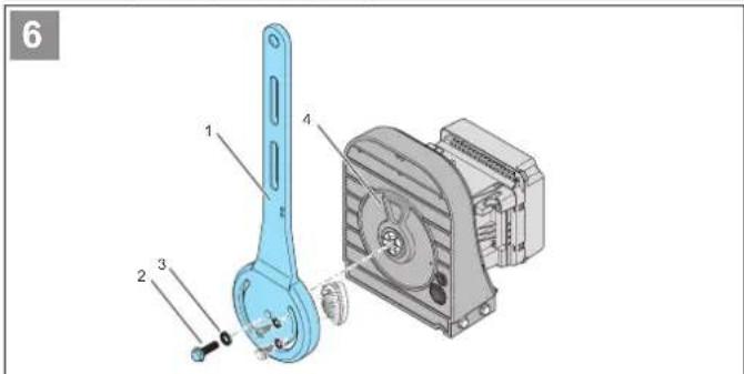
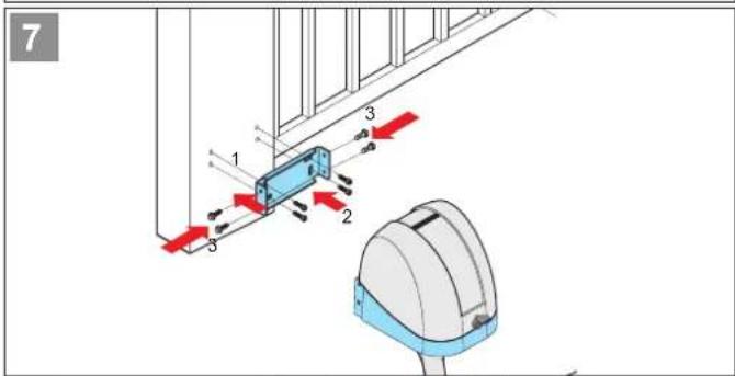
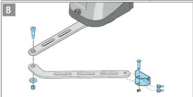
natural_image
Mechanical assembly diagram showing a bracket with mounting holes and a separate clamp mechanism (no text or symbols)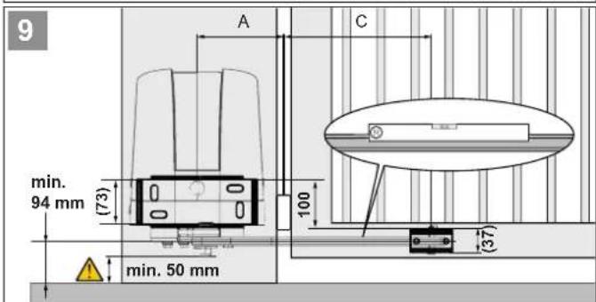
15. Short instructions for installation
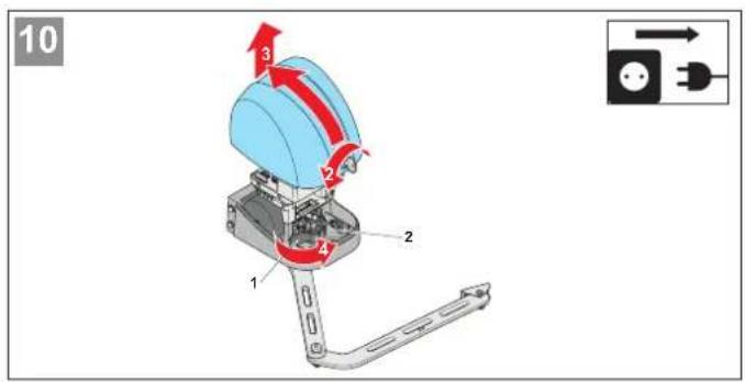
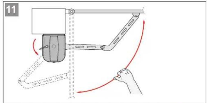
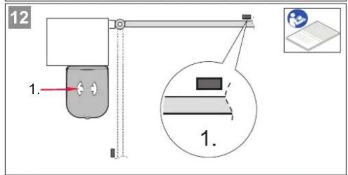
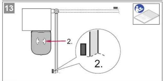
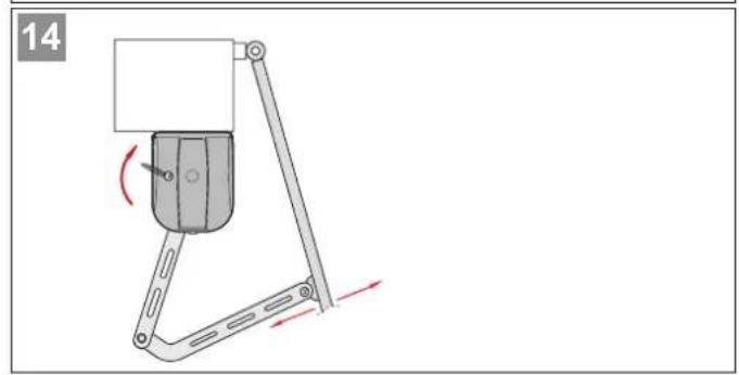
natural_image
Mechanical device with lever mechanism and rotation arrow (no text or symbols)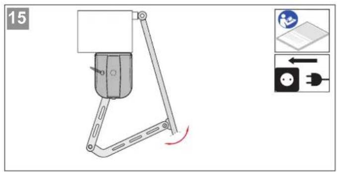
16. Setting options for the DIP switches and connection diagram for twist AM
You can select different functions via the DIP switches. The following table summarises the various setting options.
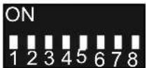
Fig. DIP switches

INFORMATION
- In the factory setting, all DIP switches are set to "OFF."
- If a safety contact strip is connected at SAFETY 1 or SAFETY 2, the settings of DIP switches 1–3 have no effect.
The reaction with the safety contact strips is always EMERGENCY STOP with subsequent partial reversion.
Overview of setting options for the DIP switches
| DIP switches Function Effect | |||
| 1 | OFF  | SAFETY 1, exterior photocell, CLOSE gate movement | SOFT STOP, full reversion |
| ON | SOFT STOP, partial reversion | ||
| 2 | OFF  | SAFETY 2, interior photocell, OPEN gate move- | No reaction |
| ON SOFT ST | OP, partial reversion | ||
| 3* | OFF  | SAFETY 2, interior photo-cell, CLOSE gate move-ment | SOFT STOP, no reversion |
| ON | SOFT STOP, partial reversion, full reversion** | ||
| 4 | OFF  | Power-saving mode | Activated |
| ON | Deactivated | ||
| 5 | OFF  | Pre-warning time light blinks for an additional | Warning light flashes during a gate movement |
| ON Warning | 4 seconds before the operator starts. The pre-warning time can be adjusted via SOMlink | ||
| 6 | OFF  | Automatic closing, only with photocell | Normal mode |
| ON | Automatic closing function | ||
| 7 | OFF  | Basic configuration | Master gate operator works as inactive leaf |
| ON | Master gate operator works as active leaf | ||
| 8 | OFF  | Basic configuration | Master gate operator is installed on the right gate leaf |
| ON | Master gate operator is installed on the left gate leaf | ||

Factory setting
* The setting of DIP switch 3 only applies for photocells.
** Only with automatic closing function (DIP switch 6 ON).
16. Setting options for the DIP switches and connection diagram for twist AM
Fig. Connection diagram
Control unit for master
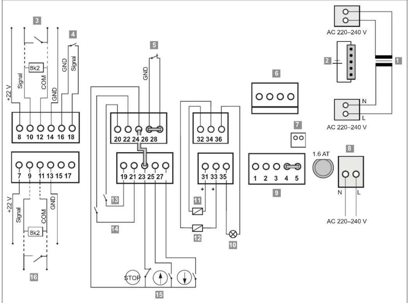
flowchart
graph TD
    A["3 Signal"] --> B["8k2 COM"]
    B --> C["8 10 12 14 16 18"]
    D["4 Signal"] --> E["+22 V"]
    F["5 GND"] --> G["20 22 24 26 28"]
    H["6 32 34 36"] --> I["31 33 35"]
    J["7 N L"] --> K["AC 220-240 V"]
    L["8 1.6 AT"] --> M["N L AC 220-240 V"]
    N["9 1 2 3 4 5"] --> O["STOP"]
    P["10 11"] --> Q["STOP"]
    R["11 12"] --> S["STOP"]
    T["12 13"] --> U["STOP"]
    V["13 14"] --> W["STOP"]
    X["14 15"] --> Y["STOP"]
    Z["15"] --> AA["STOP"]
    AB["+22 V"] --> AC["Signal"]
    AD["+22 V"] --> AE["COM"]
    AF["+22 V"] --> AG["GND"]
    AH["16"] --> AI["Signal"]
Fig. Connection diagram
Control unit for slave
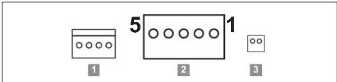
1) Transformer
2) Accumulator
3) Safety device, interior
4) Multi-function relay, MUFU, maximum of AC 24 V/DC 1 A
5) EMERGENCY STOP, when connecting, remove jumpers 26 and 28
6) Motor 2
7) Emergency release for master
8) Mains connection
9) Motor connection for slave gate operator/Motor 1, in factory state with a jumper between PIN 4 and 5
10) Warning light, WL, DC 22 V–34 V (max. 25 W)
11) Electric lock 1, 15 W
12) Electric lock 2, 15 W
13) Pulse active/inactive leaf
14) Pulse active leaf
15) 3-way button, when connecting, remove jumpers 23 and 24
16) Safety device, exterior
Slave
1) Motor connection
2) Connecting cable connections
3) Signal, emergency release
© Copyright 2020 All rights reserved.
- EN TRANSLATION OF THE ORIGINAL INSTALLATION AND OPERATING MANUAL
- Swing gate operator
- twist AM
- Warranty
- Contact data
- Feedback on this Installation and Operating Manual
- Copyright and proprietary rights
- About this Installation and Operating Manual 4
- General safety instructions 8
- Description of function and product 10
- Tools and protective equipment 17
- Declaration of Installation 17
- Installation 18
- Electrical connection and special functions 26
- Initial operation 36
- Radio 42
- Function test and final test 45
- Operation 46
- Maintenance and care 52
- Troubleshooting 54
- Taking out of operation, storage and disposal 59
- Short instructions for installation 61
- Setting options for the DIP switches and connection diagram for twist AM 63
- Storage and circulation of the Installation and Operating Manual
- www.sommer.eu
- Important for translations
- Description of the product type
- Target groups of the Installation and Operating Manual
- Explanation of symbols and notes
- ! Signal word
- ! DANGER
- WARNING
- CAUTION
- NOTE
- INFORMATION
- Special warning symbols and mandatory signs
- Information regarding the depiction of.text
- Intended use of the operator
- Improper use of the operator
- Qualifications of personnel
- Qualified specialist for installation, commissioning and disassembly
- Instructing the user and handover of documents
- Information for the user
- General safety instructions
- Basic safety instructions for operation
- Danger if not observed!
- Danger due to electric current!
- Danger due to use of the operator with incorrect settings or when it is in need of repair!
- Danger of hazardous substances!
- Danger of crushing and shearing!
- Danger of tripping and falling!
- Danger due to projecting parts!
- Additional safety information for the radio remote control
- Notes and information on operation and remote control
- Simplified Declaration of Conformity for radio systems
- Description of function and product
- The operator and its mode of operation
- Safety equipment
- Product designation
- Explanation of tool symbols
- Tool symbols
- Scope of delivery
- Scope of delivery of set for 1-wing gates
- Overview of gate operator
- Definitions
- Master gate operator
- Slave gate operator
- Active leaf
- Inactive leaf
- Left gate/right gate
- Dimensions and weights
- Tools and protective equipment
- Declaration of Installation
- Required tools and personal protective equipment
- Declaration of Installation
- Important notes and information
- DANGER
- Danger due to unstable falling parts!
- Risk of eye injury!
- Risk of injury to feet!
- Risk of injury to hands!
- Installation
- Preparing for installation
- Check the existing gate mechanism and installation posts
- Fastening dimensions on posts
- Removing unsuitable components
- Definition of master/slave gate operator
- Pre-assembling the operator arm
- Installing the blocking element
- Installing the operator arm
- Installing the operator arm
- WARNING! Danger of crushing and shearing!
- Installing the post fitting
- Installing the operator
- CAUTION! Risk of injury to feet!
- Installing the gate arm
- Checking for freedom of movement
- Adjusting the blocking elements
- Setting gate OPEN blocking element
- Setting gate CLOSE blocking element
- Installing the gate leaf fitting
- Installing accessories
- Position of photocells
- Testing the provisional connection
- Disconnect the control unit from the mains voltage
- Danger due to hot parts!
- Electrical connection and special functions
- Overview of control unit
- Connection options on the master and slave gate operator
- Overview of the LEDs
- Basic configuration
- Preparing connections for the various functions
- Connecting slave gate operator
- Connecting the warning light (WL)
- Terminal Function
- Overview of LED warning light (WL)
- Connecting photocells
- "3.1 The operator and its mode of operation".
- 2-wire photocell
- 4-wire photocell
- Overview of LED for warning light (SAFETY 1 and SAFETY 2)
- Connecting safety contact strip
- Connecting an external EMERGENCY STOP
- Overview of LED for Stop (yellow)
- Connecting an electric lock (ELock)
- Overview of LED for ELock (green)
- Connecting control elements
- Multi-function relay (MUFU)
- Connecting mains power supply
- DANGER! Danger due to electric current!
- Overview of LED for status
- Installing and removing the accumulator
- Installing the accumulator
- Removing the accumulator
- Information on SOMlink
- Important notes and information
- Crushing and shearing!
- Programming of end positions and operating forces
- Pre-conditions
- Basic configuration and preparations
- Programming a 1-leaf gate
- Programming the active leaf
- The operator starts its programming process automatically.
- Optional
- Programming a 2-leaf gate
- Programming the inactive leaf
- Obstacle detection event
- Obstacle detection event during programming of end positions
- Detecting obstacles during the force programming run
- Setting the automatic closing function
- Activating the automatic closing function
- Shortening the hold open time
- Activating pre-warning time of the warning light
- Initial operation
- Final commissioning work
- Setting options for the DIP switches
- Factory setting
- Radio
- Information on SOMloq2
- Programming a handheld transmitter
- Explanation of the LEDs for radio channels CH 1–4
- If the memory capacity has been reached
- Information on Memo
- Overview of the time sequences
- Cancelling programming mode
- Deleting transmitter button from the radio channel
- Deleting transmitter completely from the receiver
- Deleting radio channel in the receiver
- Deleting all radio channels in the receiver
- Programming an additional handheld transmitter by radio (HFL)
- Prerequisites for programming by radio
- Example:
- Restrictions
- Checking the force setting and obstacle detection
- Danger of entrapment!
- Handover of the gate system
- Important notes and information
- Danger due to irregular or omitted maintenance and testing!
- Handover to the user
- Performing obstacle detection
- See also Chapter "12. Maintenance and care".
- Setting power-saving mode
- In the event of a power failure
- Function of the emergency release
- Operation
- Locking the operator
- Carrying out a reset
- Resetting the safety devices
- Deleting the force values
- Deleting the position values
- Jog mode in the event of faults
- Operating modes of gate movement
- Overview of gate movements
- 2-leaf 1-leaf
- Important notes and information
- Maintenance and care
- Care
- Cleaning the gate operator
- Important notes and information
- Danger of injury to due to trapping of clothing or long hair!
- Troubleshooting
- Time sequences of LEDs for accessories in normal mode and in the case of faults
- Troubleshooting
- Troubleshooting table
- In normal mode
- Taking out of operation, storage and disposal
- Important notes and information
- Taking out of operation and disassembly
- Storage
- Disposal of waste
- Short instructions for installation
- Setting options for the DIP switches and connection diagram for twist AM
- Slave
Brand : Sommer
Model : Twist AM
Category : Garage door opener