Starglider 300 - Garage door opener Sommer - Free user manual and instructions
Find the device manual for free Starglider 300 Sommer in PDF.


| Product Type | Garage Door Opener |
| Brand | Sommer |
| Model | Starglider 300 |
| Drive Type | Belt drive |
| Motor Power | 1/2 HP DC motor |
| Power Supply | 120V AC, 60 Hz |
| Maximum Door Weight | 250 lbs (113 kg) |
| Maximum Door Height | 7 ft (2.13 m) |
| Rail Length | 10 ft (3.05 m) standard |
| Remote Control Range | Up to 300 ft (90 m) |
| Security | Rolling code technology (Sommer CodeSecure) |
| Lighting | Two 100W incandescent light bulbs (not included) |
| Door Types | Sectional, one-piece, and tilt-up |
| Operation Temperature | -20°F to 120°F (-29°C to 49°C) |
| Noise Level | Quiet operation (belt drive) |
| Dimensions (Motor Unit) | 14 x 10 x 6 in (35.6 x 25.4 x 15.2 cm) |
| Weight (Motor Unit) | 12 lbs (5.4 kg) |
| Control Options | Remote, wall console, smartphone (via add-on module) |
| Safety Features | Auto-reverse, obstruction sensor, manual release |
| Maintenance | Lubricate chain/belt annually; check sensors |
| Spare Parts Availability | Replaceable remote, wall console, rail kit, motor head |
| Warranty | Limited lifetime on motor and belt; 2 years on parts |
| Manual Included | Yes (30 pages). Downloadable PDF available |
Frequently Asked Questions - Starglider 300 Sommer
User questions about Starglider 300 Sommer
0 question about this device. Answer the ones you know or ask your own.
Ask a new question about this device
Download the instructions for your Garage door opener in PDF format for free! Find your manual Starglider 300 - Sommer and take your electronic device back in hand. On this page are published all the documents necessary for the use of your device. Starglider 300 by Sommer.
USER MANUAL Starglider 300 Sommer
natural_image
3D technical illustration of a rectangular electronic device with mounting base and internal components (no text or symbols)starglider 300
GB Installation and Operating Instructions 1 - 28

Contents
General Tips 2
Symbols 2
Safety Instructions 2
Normal Use 2
Permitted Gate Dimensions 3
Technical Data 3
Dimensions 3
Components of Drive System 3
EU Manufacturer's Declaration 3
General Instructions 4
Safety Instructions 4
Tools 4
Specifications 4
Installation tips 5
General Preparation 5
Installation 6
Safety Instructions 6
Location of Installation 6
Foundation 6
Installation to Ground 6
Mounting of Rack 7
Positioning of Stops 7
Commissioning 9
Safety Instructions 9
Teaching in of Drive 9
Teaching in of Hand-held Drive 9
Operation 10
Safety Instructions 10
Opening the Gate 10
Closing the Gate 10
Pulse Sequence of Door Movement 10
Reset of Control System 10
Emergency Release 11
Function of Button 2 11
Intermediate Stop 11
Stop Forced by Obstacle 11
Functions and Connections ..... 12
General Tips 12
Overview Control System 12
DIP Switches 1 - 8 12
Radio Receiver 13
Obstacle Detection (DIP 1, 2 + 3) 14
Automatic Close-mode 14
Warning Time (DIP 5) 15
Fraba System (DIP 6) 15
Seperate Signals for Closing and Opening (DIP 7) 15
Partial Opening (DIP 8) 15
Terminal bar with 24 slots 16
Motor Circuit Board 16
Connection to Power Supply 16
Connection of Push-Buttons 16
Connection of Fraba System 17
Connection of Light Barrier 17
Connection of Safety Contact Strip 17
24 V Connection 17
Connection of Warning Lamps 18
12 V Connection 18
Floating Relay Output 18
Connection of External Antenna 18
Accessories 19
Maintenance and Servicing....21
Important Notes 21
Regular Inspection 21
Replacement of Fuses 21
Additional information....22
Disassembly 22
Disposal 22
Warranty and After-Sales Service 22
Troubleshooting....23
Additional Tips for Troubleshooting 24
Spare Parts List 25
Glossary 26
General Tips
Symbols

Warning symbol: Indicates a potential risk. Failure to follow instructions may result in serious injury!

Note symbol: Information, useful advice.
Refers to the relevant illustration in the document.
Safety Instructions
General
• These Installation and Operating Instructions must be read, understood and observed by all persons installing, operating or maintaining the drive mechanism.
• Installation, connection and commissioning of the drive mechanism may only be carried out by qualified specialists.
- The drive system may only be mounted onto properly aligned gates. If installed in incorrectly aligned gates, there is a risk of serious injury or damage to the drive system.
- The manufacturer shall not be liable for damages or disruptions due to non-compliance with the Installation and Operating Instructions.
- Please ensure that the Installation and Operating Instructions are at all times accessible to all persons operating the gate.
- Observe and comply with the locally applicable accident prevention regulations and EU standards.
- Observe and comply with the directive on "Power-driven Windows, Doors and Gates - ZH 1/494" issued by the Employers' Liability Insurance Association (mandatory for operator in Germany).
- Prior to carrying out any work on the drive system, disconnect it from the power supply and secure it against inadvertent switching on.
- Only use the manufacturer's original spare parts, accessories and fixing material.
Storage
- The drive mechanism may only be stored indoors, in a dry environment at an ambient temperature of between -20^ and +50^ . - Store drive system as shown below.
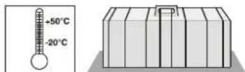
Operation
- The drive mechanism may only be operated if a risk-free force tolerance has been set. The force tolerance must be set as low as is required to ensure that the gate's closing force does not constitute a risk (see section "Force settings").
- Keep your hands clear of the moving gate or any other moving parts.
- Keep children, disabled persons and animals away from the gate.
- Only drive through the gate when it is fully opened.
- There is a risk of injury from being trapped or cut on the gate system's moving parts or edges.
for Radio Remote Control
- The radio remote control may only be used for equipment and systems in which defective remote operation of the transmitter or receiver does not constitute a risk to people, animals or property, or in cases where this risk is eliminated by means of additional safety facilities.
- The user must be made aware of the fact that the remote control of equipment with accident risk potential may only occur, if at all, when the equipment concerned is clearly visible.
- Radio remote control may only be used if movement of the gate can be supervised and there are no persons or objects in the area of movement.
- Store the hand-held transmitter in such a way that there is no risk of it being accidentally operated by, for instance, children or animals.
- The operator of this radio-controlled equipment is not in any way protected against interference from other telecommunication systems and facilities (e.g. other radio-controlled equipment that is licensed to operate at the same frequency range). Should serious interference be encountered, please contact your nearest telecommunications office with interference measuring facilities (radio signal localisation)!
- Do not use hand-held transmitters near locations or installations that are susceptible to radio interference (e.g. airports, hospitals).
Rating Plate
The rating plate is located on the cover of the control unit housing.
Exact type designation and date of manufacture (month/year) of the drive are to be found on the rating plate.
Normal Use
- The drive is designed for the exclusive purpose of opening and closing sliding gates (according to EN 12433-1), hereafter referred to as gates. Any other use does not constitute normal use. The manufacturer accepts no liability for damage resulting from use other than normal use. The user accepts sole responsibility for any risks thereby incurred. Improper use shall void all warranty.
- Gates operated automatically with a drive must comply with the applicable standards and directives as amended: e.g. EN 12604, EN 12605. The drive mechanism may only be used, if in a technically perfect condition, and in compliance with these Installation and Operating Instructions, particularly regarding correct and responsible use.
• The gate may not be installed at a slope. - The runner rail must be installed in such a way that water can drain off in order to prevent the formation of ice in winter.
- Ensure that the gate is sliding smoothly on the rail. Otherwise, the sensors of the drive system may not detect obstacles and might fail to halt the gate.
- The gate must be equipped with stops at both the open and closed position, as it might otherwise be dislocated from the rail in the event of an emergency release.
- Any defects that may impair the safe operation of the equipment should be eliminated without delay.
- The gate wings must be stable and warp-proof, i.e. they should not bend or warp during opening or closing operations.
- The drive mechanism is unable to compensate for any defects in the gate or incorrect installation.
- Do not operate the drive in areas where there is a risk of explosion.
- Do not operate the drive in rooms where the air contains aggressive gases.
General Tips
Permitted Gate Dimensions
- Length: max. 6000 mm
- Weight: max. 300 kg
- Slope: 0 %
Technical Data
Rated voltage: 230 V/AC
Rated frequency: 50/60 Hz
Operating temp. range: -20 - +50 °C
Protection class: IP 44
Max. traction force and pressure: 480 N
Rated traction: 145 N
| Rated current consumption: 0.6 | A |
| Rated power consumption: | 110 | W |
| Max. speed: | 200 | mm/s |
| Rated consumption in standby: | ~ 2 W |
| Weight: | 12.5 | kg |
| Operating factor: | 40 | % |
Workplace noise emission < 75 dBA - drive only
Dimensions
All dimensions in mm.
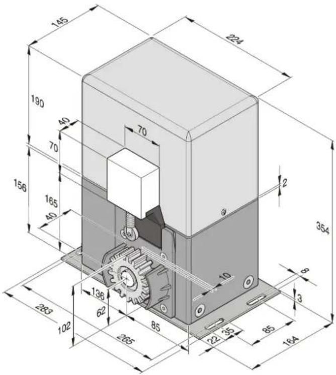
Components of Drive System
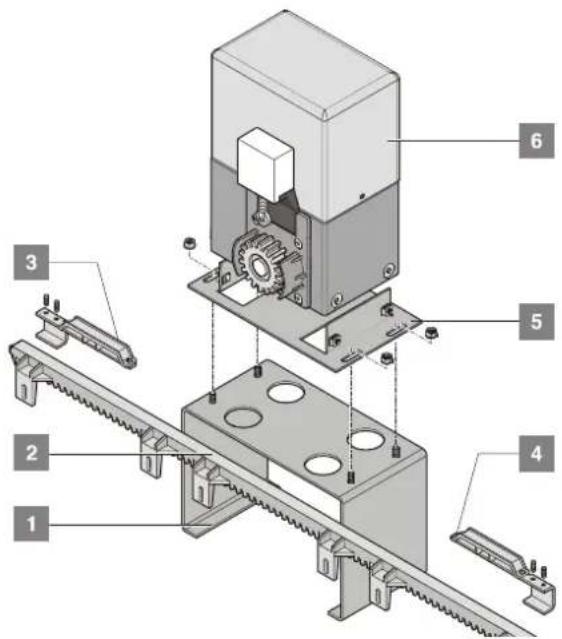
1 Base frame (optional), see chapter "Accessories"
2 Rack
3 Switch trigger right
4 Switch trigger left
5 Anchor plate
6 Drive system including control system and radio receiver
EU Manufacturer's Declaration
D-73230 Kirchheim/Teck, Germany
herewith declares that its drive system:
- starglider 300
complies with the following Directives:
- Machine Directive 98/37EU
- Low Voltage Directive 73/23/EEC
- European Directive on Electromagnetic Compatibility 89/336/EEC
The following standards/draft standards were applied: - EN 60335-1, EN 60335-2-95, DIN VDE 0801, EN 12453, EN 12445
- EN 55014-1, EN 55011, EN 61000-3-2, EN 61000-3-3
Note:
the gate system may not be commissioned until it has been established that the system in which the above drive is to be installed fulfils all specifications of the relevant EU Directives.
Preparations for Installation
Safety Instructions
- The rated voltage of the power supply must correspond to that indicated on the type plate of the drive.
- All peripheral devices must be equipped with circuit breakers for supply current according to IEC 364-4-41.
- The cabling of peripheral devices must comply with IEC 364-4-41.
- Installation, connection and commissioning of the drive mechanism must be carried out by qualified specialists.
- The gate may only be operated if there are no persons, animals or objects in the area of movement.
- Keep children, disabled persons and animals away from the gate.
- When drilling fixing holes, always wear protective goggles.
- Cover the drive during drilling to ensure that no particles can penetrate the mechanism.

The drive system must be installed on level and firm ground. The drive system may only be mounted onto properly aligned gates. Incorrect alignment of gates may lead to serious injury.
- Gates must be of a robust design as they are exposed to high traction and pressure forces. Lightweight gates in plastic or aluminium might have to be reinforced before the drive is mounted. If in doubt, contact the gate supplier.
- Remove or disable all gate locking devices.
- Use only approved fixtures (e.g. plugs, screws). The fixtures must be suitable for the ground onto which the drive is to be mounted.
- Ensure that the gate can be moved with ease.
Tools
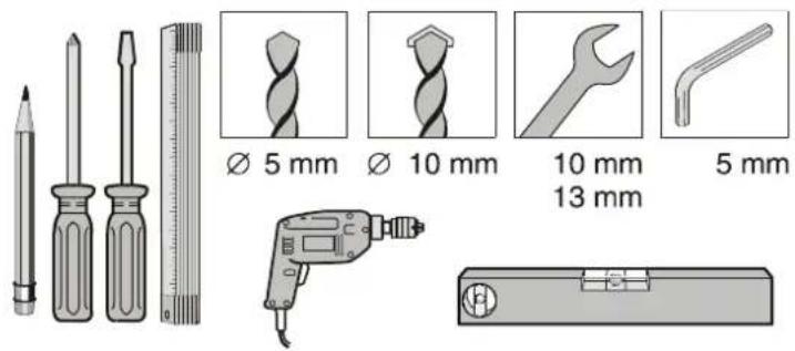
Scope of Delivery
- The scope of delivery might vary, depending on the design of the drive system.
- Prior to installation, inspect the supplied parts to ensure that no components are missing.
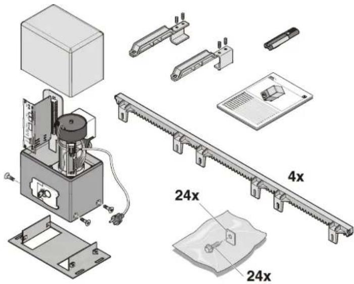
Complete drive package
Packaging (L x W x H) 1040 x 220 x 470 mm
Weight 20.5 kg
1 sliding gate drive with control system and radio receiver
1 anchor plate
1 4-key hand-held transmitter
4 1-m racks
1 assembly pack
24 screws
24 washers
1 switch trigger left, including 2 screws
1 switch trigger right, including 2 screws
1 installation and operating manual
Individual drive
Packaging (L x W x H) 310 x 215 x 370 mm
Weight 12.5 kg
1 sliding gate drive with control system and radio receiver
1 anchor plate
1 switch trigger left, including 2 screws
1 switch trigger right, including 2 screws
1 installation and operating manual
Preparations of Installation
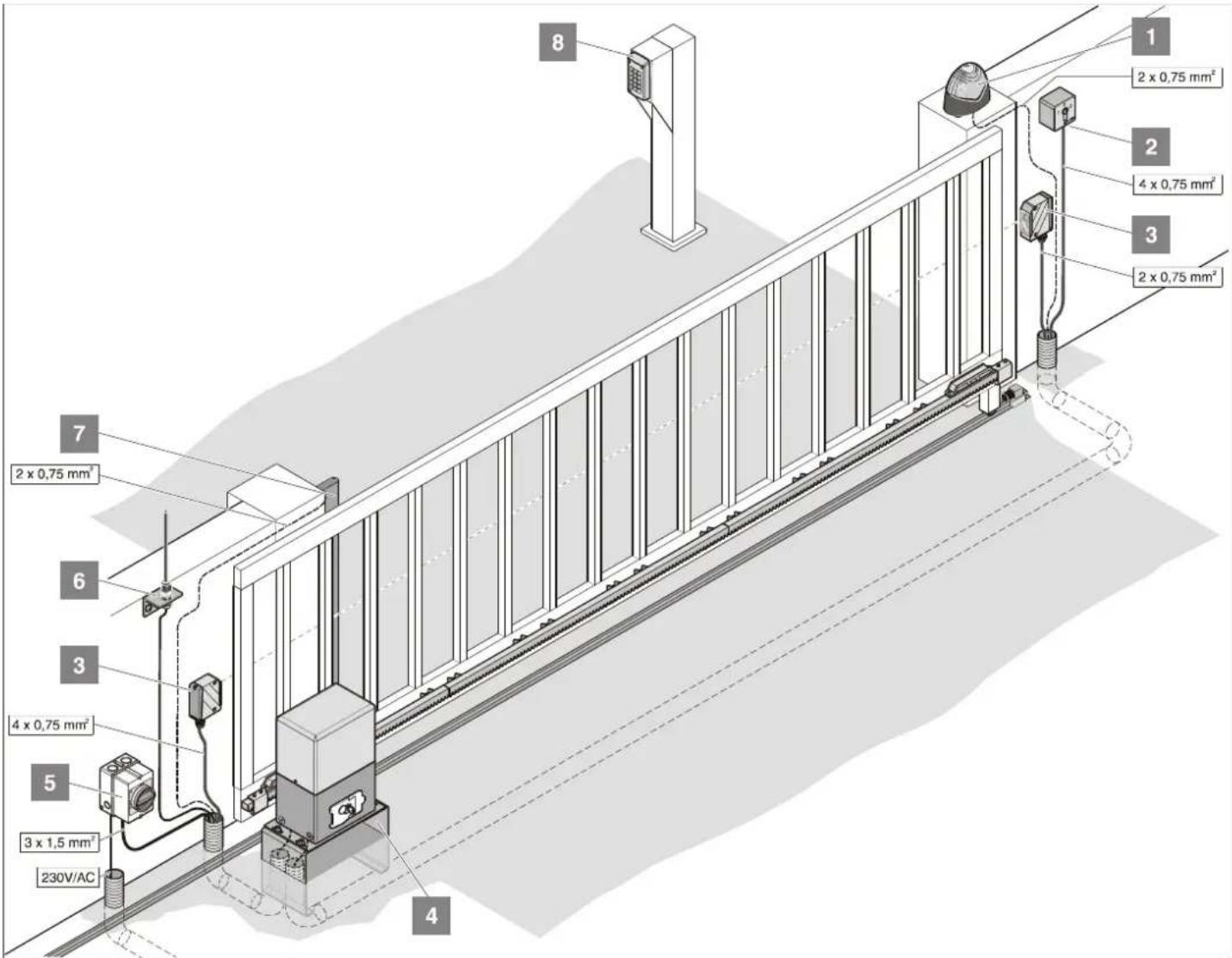
Installation Tips
- Safety devices must be installed as normally closed contacts. This ensures that safety is not compromised in the event of a defect at the drive system.
- Consult the operator on the envisaged locations for accessories.
The gate might be operated with a number of different control devices: Hand-held transmitter, Funkcody, interior push-button and key switch. For the hand-held transmitter, Funkcody and interior push-button, there is no need for cables as they are radio control devices. For more information, contact the supplier.
- Warning lamp, 24 V
- Key switch (with 1 or 2 contacts)
- Light barrier (mandatory for gates with automatic closing mechanism, see EN 12543)
- Base frame
- Main switch (lockable)
- Rod antenna (including 10-m cable)
- Safety switch strip (8.2 kOhm, Fraba System)
- Funkcody
General Preparation
- Before installing the drive, remove or disable all locking devices (electrical locks, locking bolts, etc.) of the gate.
- Ensure that the design of the gate is stable and suitable to be equipped with a drive.
- When operated, the gate may not sway to the side.
- The castors on the lower rail and/or castors on the upper rail must run smoothly without excessive friction.
- To ensure that the gate cannot derail, it must be equipped with stops at positions "Gate OPEN" and "Gate CLOSED".
• Install conduits for cables (power supply, connection of accessories such as light barrier, key switch box, warning lamp, etc.) at the base of the gate.
Installation
Safety Instructions
- For the connection of the control system to the power supply, contract an electrician.
- Ensure that the drive system is firmly secured to the ground and that the racks are properly fixed to the gate, as these devices are exposed to considerable forces during the opening and closing of the gate.
- If the opening/closing of the gate is controlled by means of a push-button, the button must be mounted at a minimum height of 1.6m above ground to prevent children from operating the gate.
- During operation of the gate, the rack may not be pressed onto the toothed wheel, as this could damage the drive mechanism.
- During installation, comply with the relevant standards such as EN 12604 and EN 12605.
Location of Installation
Left drive
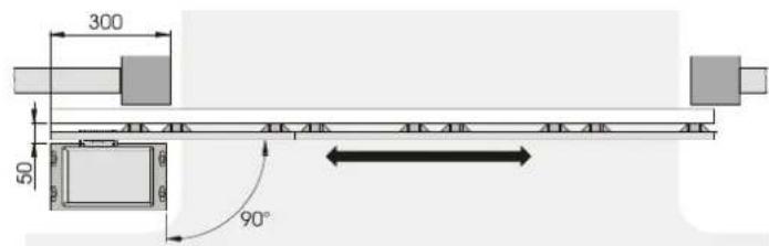
Right drive
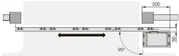
Foundation
- For cantilevered gates, the drive must be mounted between the castor blocks.
- Ensure that the foundation extends to a frost-free depth (for Germany approx. 800 mm).
• The foundation must be hardened and level. - For the dimensions of the foundation, see figure below.
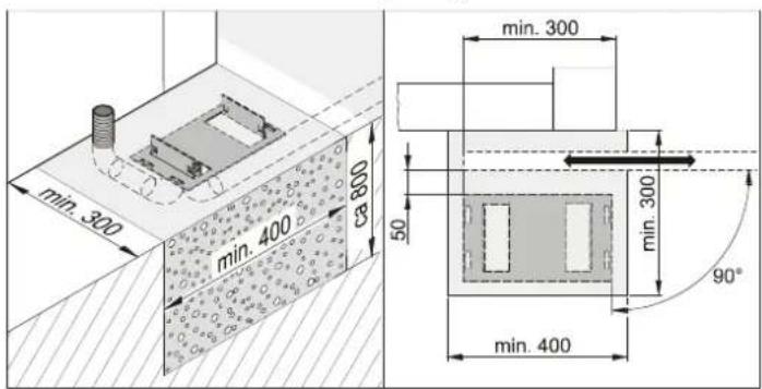
Installation to Ground
Installation to ground
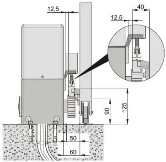
Installation with stay bolts
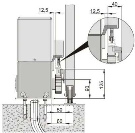
Procedure:
i Dispose of packaging material according to the applicable statutory regulations.
- Remove drive system from packaging.
- Insert cables into conduits and label for subsequent connection.
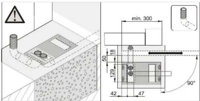
Installation
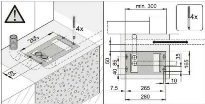
- Position anchor plate.
• Mark boreholes and drill holes. - Insert plugs and stay bolts (if any).
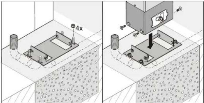
- Secure anchor plate. Check clearances.
- Position drive onto the anchor plate and secure with screws.
- Insert cables.
Mounting of rack
The complete drive package comes with 4 racks of 1 m length. If you require additional racks, please contact your supplier.
- Mount the first rack at the opening edge of the gate. To mark the holes for the securing bolts, position the respective rack over the toothed wheel.
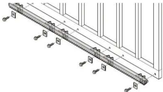
- Secure rack to the gate, using appropriate fixtures (e.g. supplied screws). Secure rack at all six fixing points to the gate.
- Unlock drive.
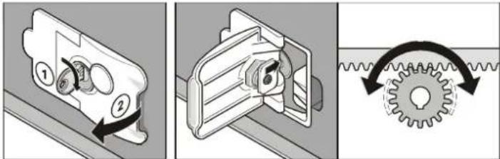
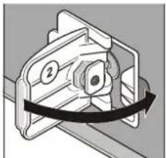
- Turn key (1) clockwise by 90^ and pull lever (2) until it engages. The drive is now released and the gate can be moved by hand.
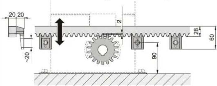
- Ensure that the rack is not pressed onto the toothed wheel in any gate position, as the gear system could otherwise be damaged.
- Alignment of rack:Move gate carefully back and forth. Adjust the rack and toothed wheel in such a way that there is a clearance of approx. 2 mm along the entire length of the gate. To adjust the distance between rack and toothed wheel, adjust the screw settings in the long slots.
Positioning of Stops

Caution!
In the event of an emergency release, the gate might open/close automatically.
- Unlock drive.
Stop for position gate CLOSED
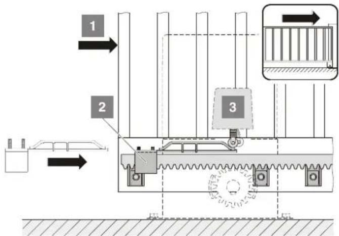
- Close gate until it is position CLOSED (1).
- Push switch trigger (2) to the end switch (3) to actuate the switch (clicking noise).
- Secure switch trigger (2) using the screws supplied.
Installation
Stop at position gate OPEN
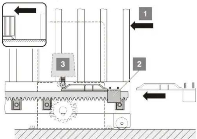
- Open gate until it is position OPEN (1).
- Push switch trigger (2) to the end switch (3) to actuate the switch (clicking noise).
- Secure switch trigger (2) using the screws supplied.
natural_image
Mechanical component diagram showing a bracket with two circular features and a black belt (no text or symbols)- Lock drive:
natural_image
Diagram of a mechanical switch or bracket with a numbered component and directional arrows (no text or symbols)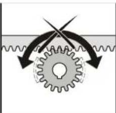
natural_image
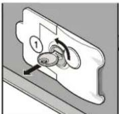
Diagram of a gear mechanism with directional arrows indicating motion (no text or symbols)Close lever (2) - turn key (1) anticlockwise by 90° and remove it: The drive engages and the gate cannot be opened by hand.
Connection to power supply

The drive is supplied with a power supply cable. Do not use any other cable for connection to the mains. After completion of the installation, cut power supply cable to the required length and insert in the conduit. The power cable is not suitable for continuous operation or outdoor installation.
- For the connection of the drive system to the power supply, contract an electrician.

The connection must be established according to EN 12453 (single-pole circuit break). Install main switch with lock (single-pole switch-off) in order to prevent inadvertent switching on of the system during maintenance or servicing.
- Prior to carrying out any work on the drive system, disconnect it from the power supply and secure it against inadvertent switching on.
- We recommend installing a protective motor switch to protect the drive system against surges.
- During work at the control system, protect it against the elements (rain, snow, etc.).
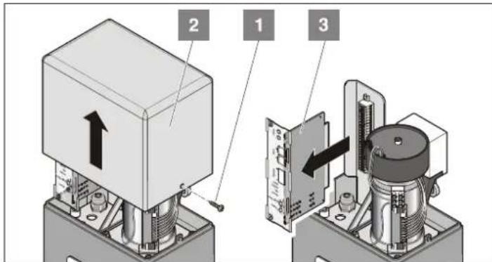
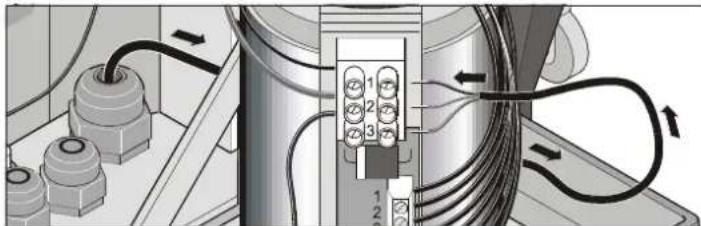
- Loosen screws (1). Remove cover (2).
- Pull out control unit (3).
natural_image
Diagram of electrical connections with numbered components and directional arrows (no text or symbols)- Connect power supply cable:
1 Live conductor (L) 230 V AC
2. Neutral conductor (N)
3. Earth conductor (PE)
- Tighten cable screws; block unused conduit channels using a piece of cable or similar material.
- Connect control system (3), ensure correct pole connection.
Check direction of drive
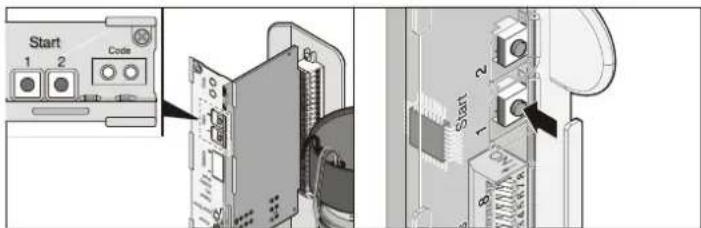
- Close gate and press button (1).
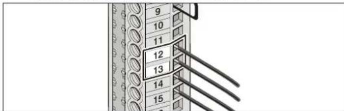
The first movement after switching on the main switch must be in direction gate OPEN. If the first movement is in direction gate CLOSED, exchange gate wires at terminals 12 + 13.
- Replace cover (2) and tighten screws (1).
Commissioning
Safety Instructions
After the drive system has been installed, the person responsible for the installation must complete an EU Declaration of Conformity according to Machine Directive 98/37/EU and attach a CE mark at the type plate of the drive. This also applies in cases where the owner of the system is a private person, as well as to manually operated gates that have been upgraded with a drive. These documents as well as the Installation and Operating Instructions must be handed over to the owner of the gate system.
The force settings are relevant for the system's safety and must therefore be adjusted with special care and attention. In the event of inappropriate force settings, there is a risk of damage to persons, animals and property. Adjust force settings to the lowest possible value to ensure that obstacles are immediately detected and the gate movement is stopped.
Teaching in of Drive
The control unit is equipped with an automatic force setting facility. When the gate is opened or closed, the control unit automatically detects the force required and stores these values when the end position is reached..
- Locking of Drive
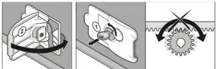
- Close lever (2) - turn key (1) anticlockwise by 90^ and remove it.: The drive engages and the gate cannot be opened by hand.
- Move the gate by hand until it engages in the drive system (loud clicking noise).
- Activate the main switch.
Control System Reset
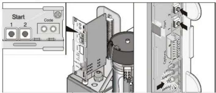
- Press and hold buttons (1+2) until the LED (warning lamp) is off
- Release buttons (1+2): LED (warning lamp) is flashing; force values are deleted.
- Closing of Gate
Complete the following procedure 2x:
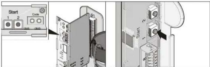
- Press button (1)
1xGate opens until it reaches the switch trigger (end position for gate OPEN)
• LED (warning lamp) is flashing - Press button (1)
1xGate closes until it reaches the switch trigger (end position for gate CLOSED)
• LED (warning lamp) is flashing - LED (warning lamp) is continuously on; force values are read.
- Check end positions for gate OPEN and CLOSED by repeatedly opening and closing the gate. If necessary, adjust end positions until the gate can be fully opened and closed.
Soft run length for gate CLOSED min. 500 mm.
Check force settings
Each time the gate is operated, the control system checks whether the stored force values correspond to the actual values and automatically adjusts the settings when the end positions are reached. For details on how to check the force values, refer to chapter "Maintenance and Servicing".
Teaching in of Hand-Held Transmitter
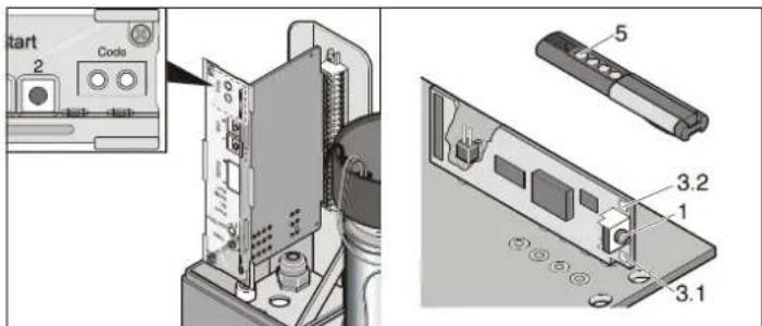
- Press teach-in button (1)
- 1x for channel 1; LED (3.1) is on
-
2x for channel 2, LED (3.2) is on
-
Press desired button at the hand-held transmitter (5). The respective signal is transmitted to the radio receiver.
-
LED is off - The teach-in process is completed.
-
If no other code signal is transmitted within 10 seconds, the radio receiver switches to standard operation.
- Continue with teaching in all other hand-held transmitters by repeating the above procedure. The system caters for maximum 112 codes.
Operation
Safety Instructions
- Keep children, disabled persons and animals away from the gate.
- Keep your hands clear of the moving gate or any other moving parts.
- Only drive through the gate when it is fully opened.
- There is a risk of injury from being trapped or cut on the gate system's moving parts or edges.
Opening the Gate
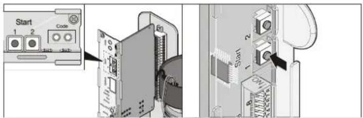
- Press push-button (1) or key at the hand-held transmitter 1x.
- If the gate is moving in direction OPEN, it is stopped. This function is determined by the settings of DIP switch 7.
- If the button is pressed again, the gate closes.
Closing of Gate
- Press push-button (1) or key at the hand-held transmitter 1x.
- If the gate is moving in direction CLOSED, it is stopped. This function is determined by the settings of DIP switch 7.
- If this button is pressed again the gate opens.
Pulse Sequence of Door Movement
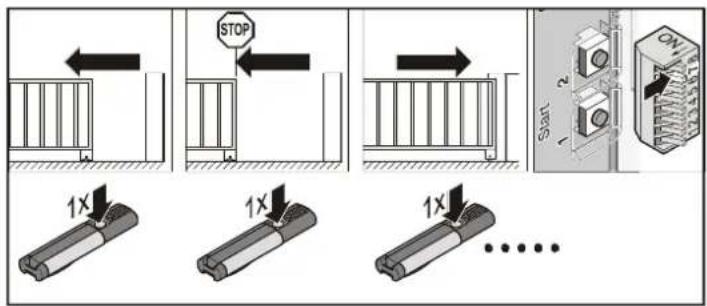
Default settings for all drives
• DIP 7 OFF:
- open - stop - close - stop - open - etc.
Adjust pulse sequence with DIP switch 7.
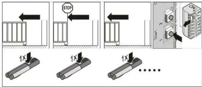
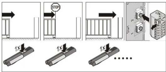
• DIP 7 ON:
- button 1: open - stop - open - stop - etc.
- button 2: close - stop - close - stop - etc.
Reset of Control System
All stored values (e.g. runtime, force for opening, etc.) are deleted. Subsequently, teach-in procedure must be repeated. A reset of the control system is required:
- if the maximum speed or the maximum force are to be adjusted (see TorMinal manual).
- if the drive settings are incorrect (incorrect teach-in) or if the gate has been modified.
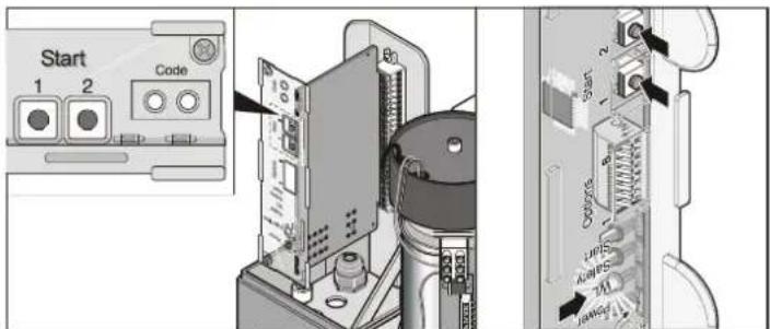
- Press and hold buttons (1+2) until the LED (warning lamp) is off
- LED (warning lamp) is off - the force values are deleted; release the buttons.
Operation
Emergency Release

Caution!
In the event of an emergency release, the gate might open/close automatically.

The drive can be released anytime, irrespective of the position of the gate.
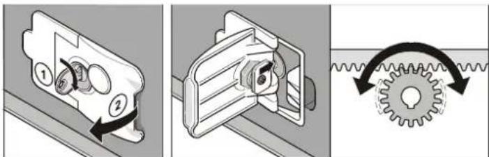
- Turn key (1) clockwise by 90^ and pull lever (2) until it engages. The drive is now released and the gate can be moved by hand.
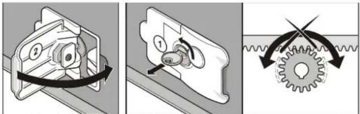
- Close lever (2) - turn key (1) anticlockwise by 90^ and remove it.: The drive engages and the gate cannot be opened by hand.
Overload Protection
If an overload occurs while the gate is being closed or opened, the drive is immediately halted by the control system. The overload protection is automatically reset after approx. 20 seconds or after a reset of the control system. The drive can again be operated normally.
Operation following a Power Failure
The force values remain saved even if a power failure occurs. The first movement of the unit following a power failure is always in direction OPEN.
Function of Button 2
For settings, see chapter "Functions and Connections".
2-channel operation (separate signals for closing and opening)
Press button 1 to open the gate; press button 2 to close the gate.
Partial opening
Press button 1 to fully open/close the gate. Press button 2 to open/close the gate partially.
Biased-off operation (activation only with TorMinal)
The gate opens, as long as button 1 is pressed. The gate closes, as long as button 2 is pressed.
Intermediate Stop
To halt the gate during travel, press the respective key at the hand-held transmitter. The drive system is halted immediately. At the next command, the drive operates in the opposite direction (see also chapter "Pulse Sequence and Gate Movement").
Stop forced by Obstacle
1. Force cut-off
- When gate closes -> drive direction is reversed
- When gate opens -> drive direction is reversed
At the next command, the drive operates in the opposite direction (see also chapter "Pulse Sequence and Gate Movement").
2. Safety input 1 triggered e.g. due to activation of safety contact strip
If the gate is halted by a signal at the safety input, the subsequent drive motion is determined by the DIP switch settings (see chapter "Obstacle Detection").
Factory Settings:
- When gate closes -> drive direction is reversed
- When gate opens -> drive direction is reversed
At the next command, the drive operates in the opposite direction (see also chapter "Pulse Sequence and Gate Movement").
3. Safety input 2 triggered e.g. due to triggering of light barrier
If the gate is halted by a signal at the safety input, the subsequent drive motion is determined by the DIP switch settings (see chapter "Obstacle Detection").
Factory Settings:
- When gate closes -> drive direction is reversed
- When gate opens -> drive is not restarted
At the next command, the drive operates in the opposite direction (see also chapter "Pulse Sequence and Gate Movement").
Functions and Connections
General Information regarding : Control Settings
- At delivery, all DIP switches are in OFF position.
- Do not apply any external voltage to the control connections, as this would completely destroy the system.
Overview of Control System
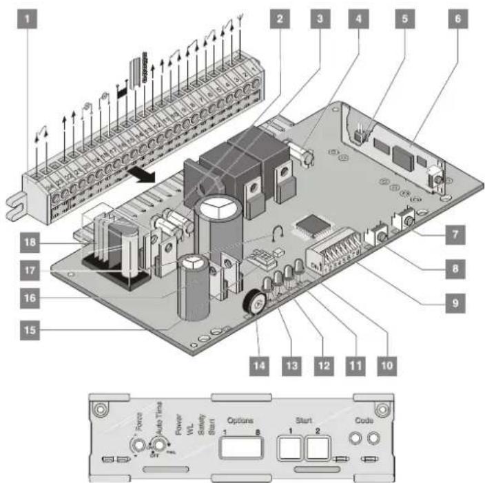
- Terminal bar with 24 slots
- Fuse of adapter for warning lamp 1, terminal 16 + 17
- Fuse of adapter for warning lamp 2, terminal 18 +19
- Fuse of 24 V adapter, terminal 14 + 15
- Adapter for external antenna
- Radio receiver
- Button 2 (T2)
- Button 1 (T1)
- DIP switches 1 - 8
- Start (LED 4) is on when a radio code is transmitted or when a button is pressed.
- Safety (LED 3) is on when a signal is received through the safety input.
- Warning lamp (WL) (LED 2) is flashing when the gate is opening/closing.
- Power (LED 1) is on when the system is powered.
- Potentiometer (P2) for timer settings of the automatic closing mode
- Adapter for TorMinal
- Protection against incorrect connection of TorMinal
- Wire bridge; if cut, soft run is disabled.
- Relay contact, terminal 23 + 24
DIP Switches 1 - 8
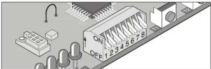
Caution! Prior to adjusting the DIP switch settings, disconnect control unit from the power supply. The new DIP switch settings are read by the system upon restart of the control unit.
natural_image
Illustration of an electronic circuit board with LEDs and connector pins (no readable text or symbols)Switch Position Function/response
Safety input 1, terminal 6 + 7
Behaviour of drive during opening of gate
1 OFF No response from drive
ON Drive motion reversed
Safety input 1, terminal 6 + 7
Selection of function: normally closed contact or 8.2 KOhm
2 OFF Normally closed contact (e.g. light barrier)
ON 8.2 KOhm
Safety input 1 terminal 6 + 7, safety input 2 terminal 8 + 9
Behaviour of drive during closing of gate
3 OFF Drive is stopped and gate is opened a little (reversed motion)
ON Drive is stopped and gate is fully opened
Automatic close mode: The gate is automatically closed 5 seconds after the light barrier has been triggered (safety input 1 or 2).
4 OFF deactivated
ON activated
Warning time for warning lamp input terminal 16 + 17
5 OFF Warning time 0 seconds
ON Warning time 3 seconds - warning lamp is flashing
Fraba system
6 OFF deactivated
ON activated
Separate signals for closing and opening
7 OFF Pulse sequence at 1st channel Button/radio channel 1 + 2:
open - stop - close - stop - open - stop - close ...
ON Pulse sequence at 2nd channel Button/radio channel 1: open - stop - open ...
Button/radio channel 2: close - stop - close ...
Partial opening
8 OFF partial opening deactivated
ON partial opening activated
- Button/radio channel 1 = open - stop - close ...
- Button/radio channel 2 = partial opening DIP switch 7 OFF
Functions and Connections
Radio Receiver Safety Instructions
- Ensure that the installation and operation of the system complies with the applicable statutory safety regulations! For more information, contact the local electricity supplier, safety authorities and trade organisations.
- The operator of this radio-controlled equipment is not in any way protected against interference from other telecommunications systems and facilities (e.g. other radio-controlled equipment that is licensed to operate at the same frequency range).
- Poor reception might be eliminated by replacing the batteries of the respective hand-held transmitter.
Display and Buttons
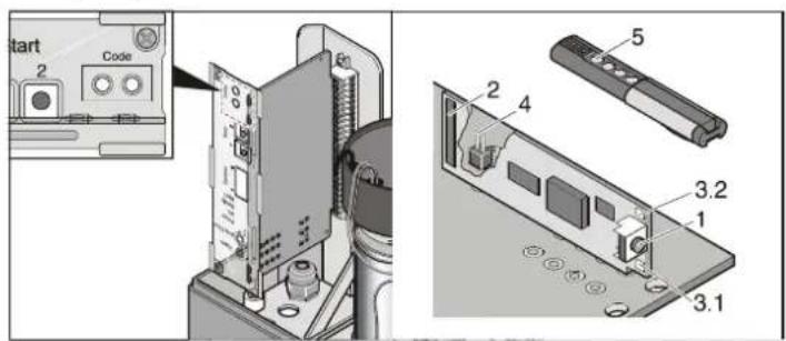
(1) Teach-in button
Press this button to select the required operating mode: teach-in mode, delete mode, standard mode
(2) internal antenna
Radio channel 2 (3.1.) is only used for 2-channel operation (separate channels for opening/closing or partial opening).
(3) LEDsIndicate the channel that is currently selected.
3.1.LED of radio channel 1
3.2 LED of radio channel 2
(4) Adapter for external antenna (4)
If the range of the internal antenna is not sufficient for the proper operation of the gate, you have the option to connect an external antenna (see chapter "Accessories").
(5) Hand-held transmitter button
Teaching in of Hand-held Transmitter
- Press teach-in button (1)
- 1x for channel 1; LED (3.1) is on
- 2x for channel 2, LED (3.2) is on
- Press desired button at the hand-held transmitter (5). The respective signal is transmitted to the radio receiver.
- LED is off - The teach-in process is completed.
- If no other code signal is transmitted within 10 seconds, the radio receiver switches to standard operation.
- Continue with teaching in all other hand-held transmitters by repeating the above procedure. The system caters for maximum 112 codes.
Deleting of Assigned Radio Codes
If one of the gate users moves house and wishes to take the hand-held transmitter with him/her, all assigned radio codes must be deleted at the receiver. For safety reasons, delete all buttons and button combinations of the hand-held transmitter!
- Press and hold teach-in button (1) for 5 seconds until at least one LED is flashing.
- Release teach-in button (1). The radio receiver is in delete mode.
- Press the button at the hand-held transmitter whose code you wish to delete. The LED is off and the respective code has been deleted from the radio receiver memory.
Repeat this procedure for all buttons and button combinations at the hand-held transmitter.
Deleting of Channels
- Press and hold teach-in button (1)
- 1x for channel 1; LED (3.1) is on
- 2x for channel 2, LED (3.2) is on.
- After 5 seconds, the LED begins to flash. After another 10 seconds, the LED is continuously on.
- Release the teach-in button (1). The selected channel has been deleted.
Deleting all Data in Radio Receiver Memory
If a hand-held transmitter has been lost, all channels at the radio receiver must be deleted for safety reasons! Subsequently, repeat the teach-in procedure for the receiver and all hand-held transmitters.
- Press and hold teach-in button (1).
- After 5 seconds, the LED begins to flash. After another 10 seconds, the LED is continuously on.
- After 25 seconds, all LEDs are on.
- Release the teach-in button (1). All channel data has been deleted.
Functions and Connections
Obstacle Detection (DIP 1, 2 + 3)
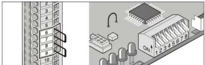
Obstacle detected while gate is opening
Force cut-off
Drive motion reversed
If a signal is received at one of the safety inputs (e.g. triggered by a person crossing the light barrier), the drive responds according to the settings of DIP switch 1.
Safety input 1, terminal 6 + 7
DIP switch 1:
OFF No response from drive
ON Drive motion reversed
DIP switch 2: Function of safety input 1, terminal 6 + 7
OFF Normally closed contact, e.g. for light barrier
ON 8.2 kOhm (safety contact strip)
Safety input 2, terminal 8 +9
No response from drive
Obstacle detected while gate is closing
If the gate is in automatic close mode, it is fully opened.
Force cut-off
Drive motion reversed
If a signal is received at one of the safety inputs (e.g. triggered by a person crossing the light barrier), the drive responds according to the settings of DIP switch 3.
Safety input 1, terminal 6 +7
DIP switch 3:
OFF Drive is stopped and gate is opened a little; drive motion reversed ON Drive is stopped and gate is fully opened
Safety input 2, terminal 8 +9
DIP switch 3:
OFF Drive is stopped and gate is opened a little; drive motion reversed ON Drive is stopped and gate is fully opened
Automatic Close Mode
For operation with automatic close mode, comply with EN 12453 (e.g. installation of light barrier). An additional light barrier must be connected to safety input 2. This barrier responds only while the gate is being closed.
The gate closes automatically after the time for GATE OPEN set at the potentiometer has lapsed. The gate can be opened by means of a push-button or hand-held transmitter signal, but cannot be closed in this way. While the gate is opening, it cannot be stopped by pressing a button. If a button is pressed while the gate is closing (automatic closing), it is fully opened. If a button is pressed during the set GATE OPEN time, the time is reset and the GATE OPEN time is restarted.
In automatic close mode, the partial opening function is deactivated.
The automatic closing mode has no effect on the warning lamps 1 + 2 (flashing as in standard mode).
Example:
- Warning lamp 1 is connected to terminal 16 + 17. Light located outside the gate.
- Warning lamp 2 is connected to terminal 18 +19. Light located inside the gate.
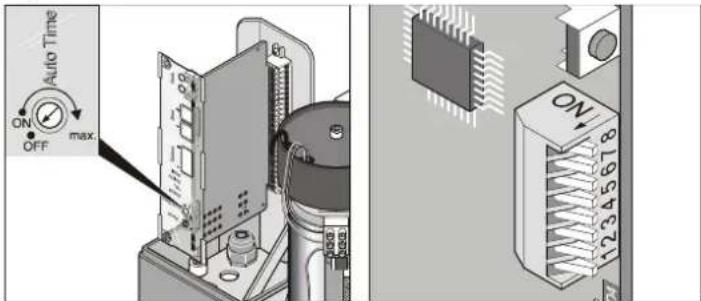
The GATE OPEN time can be adjusted at the potentiometer:
- Time adjustable between 1 and 120 seconds
- To deactivate function> turn key to left stop
Behaviour of the drive in the event of a signal at safety inputs 1+2 While gate is opening: Behaviour of the drive depends on the settings of DIP switch 1. While gate is closing: The drive opens the gate fully, irrespective of the settings of DIP switch 3.
Option 1: Automatic close mode
Automatic closing is activated as soon as the end position gate OPEN is reached; at this moment, the GATE OPEN time set at the potentiometer is started. If another command is transmitted within the GATE OPEN time, the time is reset.
Settings:
- Set potentiometer to the required time (1 - 120 seconds)
- DIP switches 7 + 8 OFF
- Other DIP switches set as required
Functions and Connections
Option 2: Automatic close mode + light barrier (DIP switch 4)
This option allows for the manual interruption of the closing motion, and for automatic closing after a set period of time after triggering of the light barrier.
The functions of option 1 apply. In option 2, the gate is automatically closed 5 seconds after the light barrier has been triggered (e.g. by vehicle passing through it). This option requires the connection of safety input 2, terminal 8 + 9.
Settings:
- Set potentiometer to the required time (1 - 120 seconds)
- DIP switches 1, 7 + 8 OFF
- DIP switch 4 ON
- Other DIP switches set as required
Option 3: Automatic close mode + safety contact strip + light barrier
This option allows for the manual interruption of the closing motion, and for automatic closing after a set period of time after triggering of the light barrier.
Similar to option 2, whereby the gate is automatically closed 5 seconds after the light barrier has been triggered.
The light barrier must thereby be connected in series with the safety contact strip to safety input 2 (terminal 8 + 9).
Settings:
- Set potentiometer to the required time (1 - 120 seconds)
- DIP switches 1, 7 + 8 OFF
- DIP switches 2, 4 ON
- Other DIP switches set as required
Warning Time (DIP 5)
You have the option to operate a warning lamp connected to warning lamp adapter 1 (terminal 16+17) or 2 (terminal 18+19). This light flashes after the push-button or the button at the hand-held transmitter has been pressed for a period of 3 seconds.
The drive is only activated after this period has lapsed. If another button is pressed in the meantime, the warning time is terminated.
DIP switch 5
OFF deactivated
ON activated, warning lamps 1 + 2 are flashing for 3 seconds
Fraba System (DIP 6)
You have the option to route the function of safety input 1 (terminal 6 + 7) to the signal interpretation of a Fraba system.
DIP switch 6
OFF deactivated
ON activated
Separate Signals for Closing and Opening (DIP Switch 7)
Button/radio channel 1: for opening, button/radio channel 2 for closing. The 2-channel mode is suitable for operation with 2 push-buttons or hand-held transmitters.
Settings: DIP switch 8 OFF, 2 buttons connected and/or 2 hand-held transmitter buttons programmed.
DIP switch 7
OFF deactivated
ON activated
Partial Opening (DIP 8)
This function allows for the partial opening of the gate.
Example:
You wish to open the gate to give access to pedestrians only. To open the gate partially with this function, you have the option to adjust the settings for control with 2 push-buttons or by radio code (hand-held transmitter, Funkcody, etc.).
DIP switch 8
OFF deactivated
ON activated, DIP switch 7 disabled
Partial opening by pressing 2 push-buttons
Install additional push-button and connect it as button 2 to terminal 4 + 5.
Push-button 1 opens the gate fully. If the gate has been opened partially by pressing button 2, it can be fully opened by pressing push-button 1.
Push-button 2 opens the gate partially, provided that the gate is first closed. If the gate has already been opened fully (push-button 1) or partially (push-button 2), it is closed when push-button 2 is pressed again.
Procedure:
- Close gate.
2 DIP switch 8 ON: partial opening is activated - Leave DIP switch 8 in position ON; if it is set to OFF, the set partial opening is deleted.
- Press push-button 2 (opening gate from position GATE CLOSED).
- The gate opens until push-button 2 is pressed again or until the gate reaches the GATE OPEN position.
- Press push-button 2 as soon as the desired position is reached.
- To close the gate, press push-button 2 again.
The opening distance for partial opening has been programmed. Next time push-button 2 is pressed, the gate is opened partially according to these settings.
To delete the settings for partial opening: Set DIP switch 8 to OFF.
Partial opening by means of
hand-held transmitter (2-channel operation)
Teach-in 2 buttons at the hand-held transmitter: e.g. button 1 assigned to radio channel 1 and button 2 assigned to radio channel 2
Radio channel 1 is assigned the same function as button 1, terminal 2 + 3,
Radio channel 2 is assigned the same function as button 2, terminal 4 + 5.
Proceed with programming as described above.
Functions and Connections
Terminal bar with 24 slots
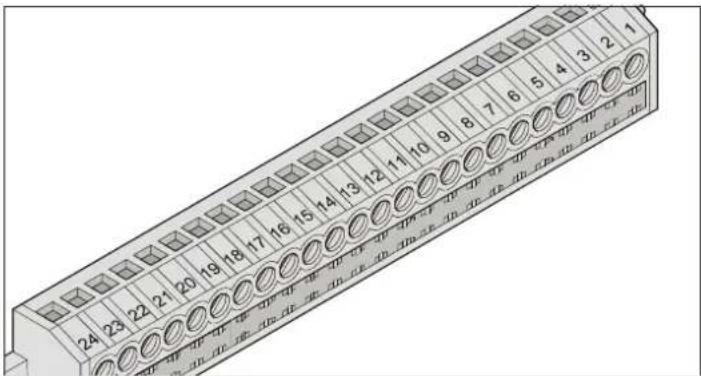
Terminal Assignment/colour Connection/description
1 not assigned Antenna 40 MHz
2+3 not assigned Push-button 1
4+5 not assigned Push-button 2
6+7 Bridge Safety input 1
8+9 Bridge Safety input 2
10+11 not assigned 24V
12 blue/black Motor circuit board (terminal 1)
13 blue Motor circuit board (terminal 5)
14+15 white Transformer
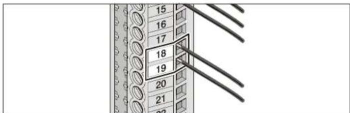
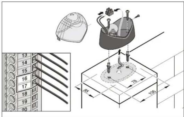
16+17 not assigned Warning lamp 1
18+19 not assigned Warning lamp 2
20+21 not assigned 12V
22 - Reverse polarity protection
23+24 not assigned Floating relay output
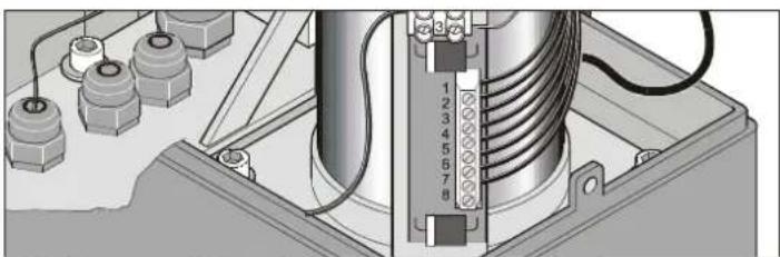
Motor circuit board
natural_image
Technical diagram of an electrical component with labeled parts and wiring (no readable text or symbols)Terminal Colour of cable Description
1 blue/black Control system (terminal 12)
2 brown End switch
3 white End switch
4 red Motor
5 blue Control system (terminal 13)
6 yellow End switch
7 green End switch
8 black Motor
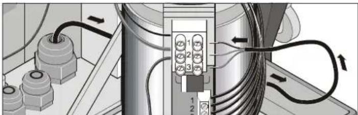
Connection to Power Supply
natural_image
Technical diagram showing electrical connections with numbered components and wiring (no readable text or symbols)Terminal Colour of cable Description
1 brown Live conductor (L) 230 V AC
2 brown neutral conductor (N)
3 yellow/green Earth conductor (PE)
Connection of Push-Buttons
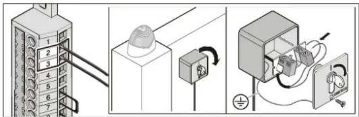
Push-button 1
Terminal 2+3
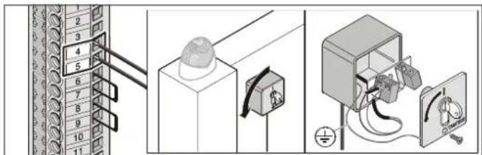
Push-button 2
Terminal 4+5
Push-button 2 is used if separate signals for opening and closing are to be defined, for the partial opening function and for biased-off operation of the buttons.
Connection of Fraba System
Connection without special analysis device; the signals are interpreted by the control system.
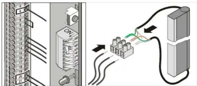
Terminal 6 Connect green cable of Fraba system
Terminal 20 Connect brown cable of Fraba system
Terminal 21 Connect white cable of Fraba system
DIP switch 6 ON
Functions and Connections
Connection of Light Barrier
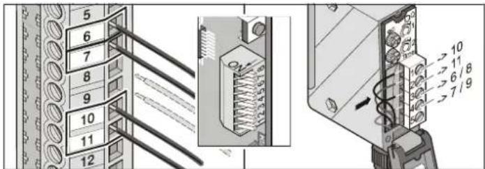
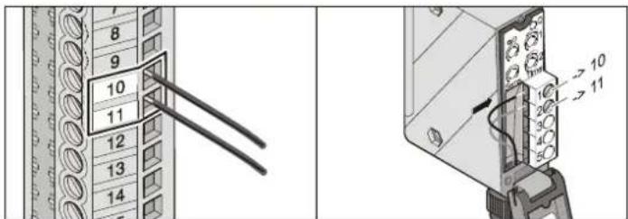
Safety input 1
Terminal 6+7: Tested adapter for floating contacts, provided that DIP switch 2 is set to OFF
Safety input 2
Terminal 8+9: Tested adapter for floating contacts, responding only while gate is being closed
Power supply
Terminal 10 24 V/DC (max. 34 V), max. 1 A
Terminal 11: Earth
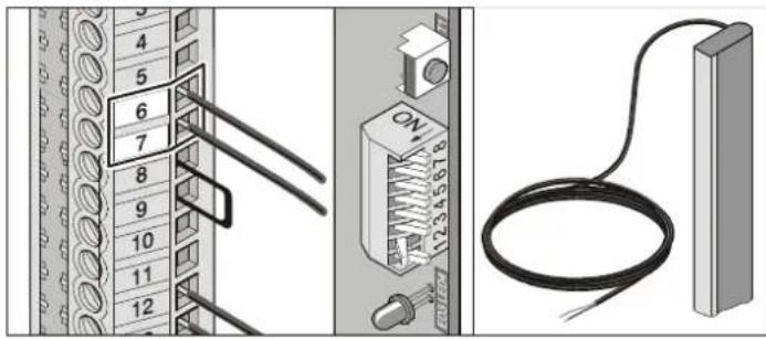
Connection of Safety contact strip
Analysis 8.2 kOhm. Connection without special analysis device; the signals are interpreted by the control system.
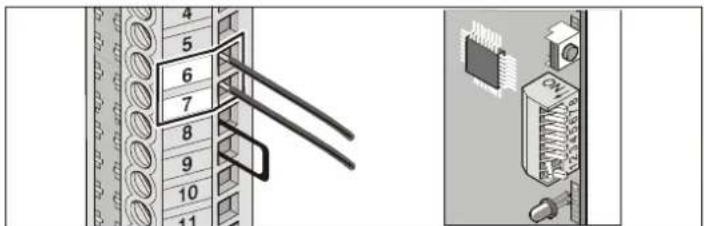
Terminal 6+7 Tested adapter for 8.2 kOhm resistor; DIP switch 2 set to ON
DIP switch 2 ON
24 V Connection
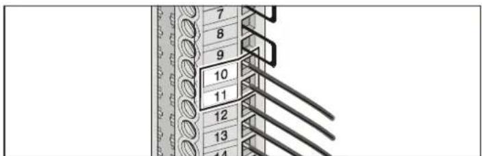
Terminal 10 24 V/DC (max. 34 V), max. 1 A
Terminal 11: Earth
Motor
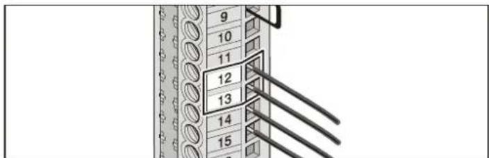
Terminal 12 blue/black
Terminal 13 blue
Exchange connections for drive mounted on the right-hand side.
Transformer
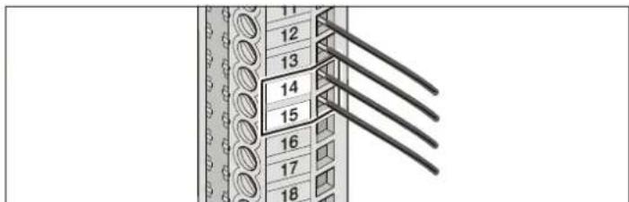
Terminal 14+15 Transformer cable (white), secondary connection 24 V AC
Connection of Warning Lamps
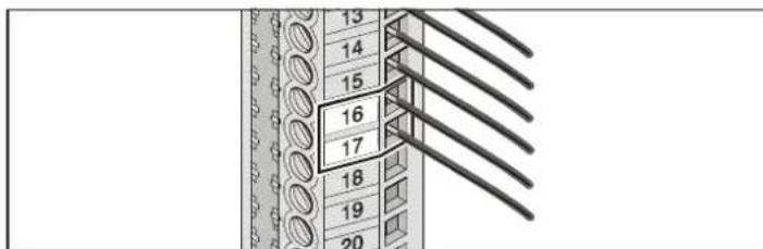
Warning lamp 1
Terminal 16+17 24 V/DC (max. 34 V), 25 W, max. 1 A, protected with 1 A slow-acting fuse
Warning lamp 2
Terminal 18+19 24 V/DC (max. 34 V), 25 W, max. 1 A, protected with 1 A slow-acting fuse
Functions and Connections
12 V Connection
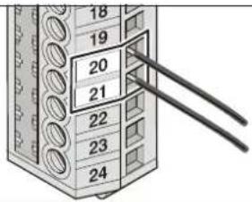
Terminal 20 12 V/DC, max. 0.1 A
Terminal 21: Earth
Floating relay output
Each time the drive is started, a pulse is present at the relay output with which, for instance, stairway lighting can be switched on via an automatic switching system.
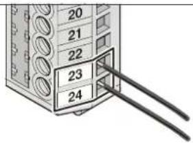
Terminal 2+3 230 V/AC, max. 5 A
To change settings, use TorMinal.
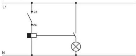
Example: Staircase lighting with automatic switching system
Connection of External Antenna
Please refer to chapter "Accessories"
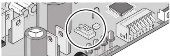
TorMinal Interface
Please refer to TorMinal operating manual
natural_image
Isometric view of an electronic circuit board with components and a magnified inset showing a component labeled 'ON' (no readable text or symbols beyond basic labels)Special Functions
Biased-off operation Maintenance monitoring
These and other functions and modes can only be activated/configured with TorMinal.
Accessories
1. Warning Lamp
2. Key Switch

Position the key switch box in such a way that the operator can see the gate, while he/she is not inside the operating area of the gate.
- Never lead the key switch cable along the power line, as this could lead to interference in the control system.
- Use a separate conduit for the key switch line.
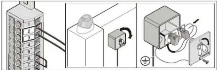
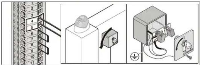
- Install key switch box at a suitable location that can be easily accessed.
3. Light Barrier
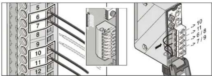
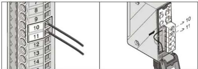
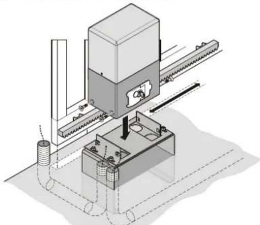
4. Base frame

For installation, observe dimensions and correct angles (see chapter "Location of Installation").
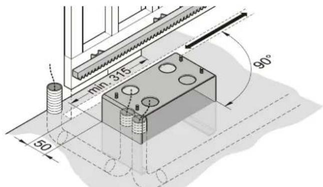
- When completing the foundation, take into account the dimensions of the base frame and cable conduits (for light barrier, etc.). For more details, please refer to chapter "Foundation".
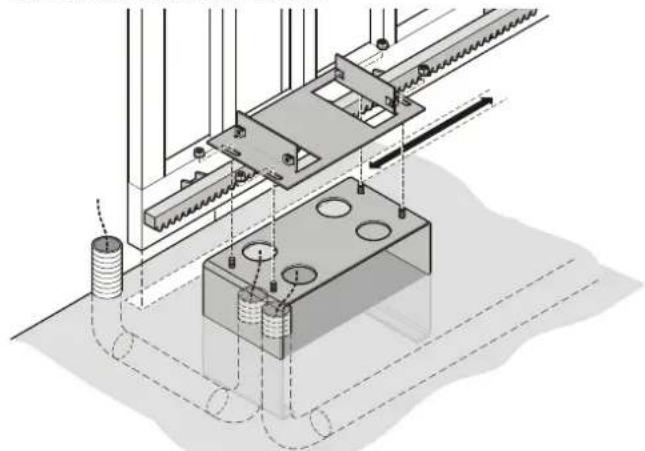
- Check dimensions and level alignment of base frame. Embed conduits and base frame in concrete.
natural_image
Technical diagram of a mechanical assembly with rollers and housing (no text or symbols)- Secure anchor plate onto the base frame.
natural_image
Isometric technical diagram of a mechanical assembly with no visible text or symbols- Position drive onto the anchor plate and secure with screws.
- Insert cables.
Accessories
5. Main Switch
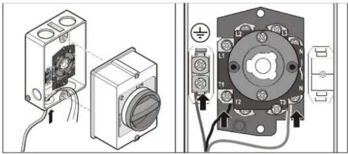
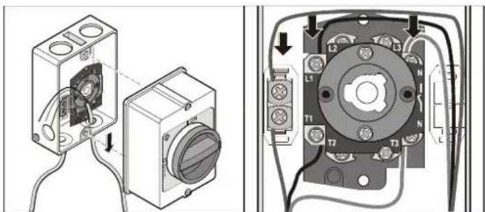
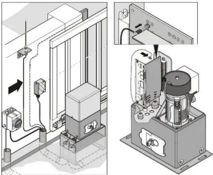
6. External Antenna
- If the internal antenna is not sufficient for the proper operation of the gate, you have the option to connect an external antenna to the system.
- Ensure that the antenna cable is laid in such a way that there is no physical impact to the radio transmitter. Install tension protection, if necessary.
- Consult the operator/owner of the system in order to find a suitable location for the external antenna.
natural_image
Technical diagram showing electrical panel installation and internal components (no text or symbols)- Connect external antenna to the respective adapter.
7 Safety contact strip
8,2 kOhm
natural_image
Diagram showing connections between a rack-mounted device, a switch, and a cable (no text or symbols present)Terminals 6+7 Tested connection for 8.2kOhm resistor DIP switch 2 ON
Fraba system
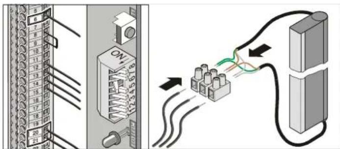
Terminal 6 Green cable from Fraba system Terminal 20 Brown cable from Fraba system Terminal 21 White cable from Fraba system
DIP switch 6 ON
Maintenance and Servicing
Important Information

Never clean the drive system with a pressure hose.
- Prior to carrying out any work on the drive system, disconnect it from the power supply and secure it against inadvertent switching on.
- Never clean the drive with alkaline or acidic solutions.
- Clean drive only with a dry cloth.
- Keep your hands clear of the moving gate or any other moving parts.
- There is a risk of injury from being trapped or cut on the gate system's moving parts or edges.
- All fixing screws on the drive must be regularly checked and retightened if necessary.
- The gate must be regularly inspected in accordance with the manufacturer's instructions.
Regular Inspection
All safety-relevant devices must be inspected and tested on a regular basis, at least once every year (see also ZH 1/494 April 1989).
Safety devices that are sensitive to pressure (e.g. safety contact strip) should be checked every four weeks to ensure proper operation (see pr EN 60335-2-95).
| Test/inspection | Behaviour of gate/drive yes/no | Possible cause | Remedy | |
| Force cut-offStop gate wing during closing operation by placing a 50 mm wide object in its path. | Drive reverse gate motion when stopped by an obstacle | yes | ·Force cut-off works properly | ·Do not change settings. |
| no | ·Force tolerance value too high; readjust with TorMinal·Gate settings incorrect | ·Reduce force tolerance until test is successful. Prior to test, open and close the gate twice watching its operation. For more details, see TorMinal manual.·Adjust gate settings, consult specialised technician! | ||
| Emergency releaseFor detailed instructions, see chapter “Emergency Release”. | The gate must open/close easily when operated by hand. (gate properly balanced) | yes | ·Everything OK! | |
| no | ·Repair emergency device device·Gate jammed | ·Inspect gate and test gate operation (see operating manual of gate). | ||
| Safety contact strip (optional)Open/close gate and interrupt motion by triggering the safety contact strip. | Gate behaviour according to settings of DIP switches 1, 2 and 3.LED “Safety” is on | yes | ·Everything OK! | |
| no | ·Ins payable, tight terminal screw loose·DIP switch settings incorrect·Contact unit defective | ·Readjust DIP switches·Shut down unit and secure against inadvertent switching on. Contact customer service department! | ||
| Light barrier (optional)Open/close gate and interrupt motion by triggering the light barrier. | Gate behaviour according to settings of DIP switches 1, 2 and 3.LED “Safety” is on | yes | ·Everything OK! | |
| no | ·Ins payable, tight terminal screw loose·DIP switch settings incorrect·Light barrier dirty·Light barrier incorrectly aligned (bracket bent or damaged)·Light barrier defective | ·Readjust DIP switches·Clean light barrier Readjust light barrier components·Shut down unit and secure against inadvertent switching on.·Contact customer service department! | ||
Maintenance and Servicing
Replacement of Fuses
- Disconnect system from the power supply.
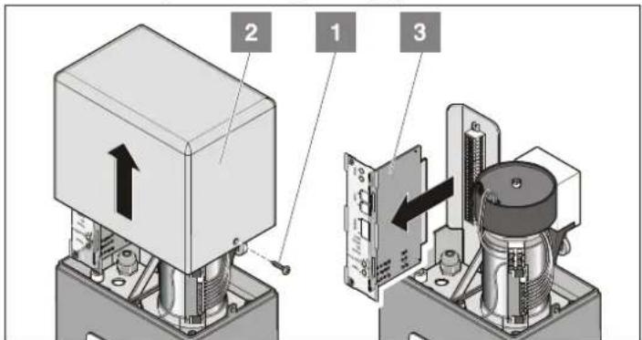
- Loosen screws (1). Remove cover (2).
- Pull out control unit (3).
- Replace defective fuse; use only 1 A slow-acting fuses.
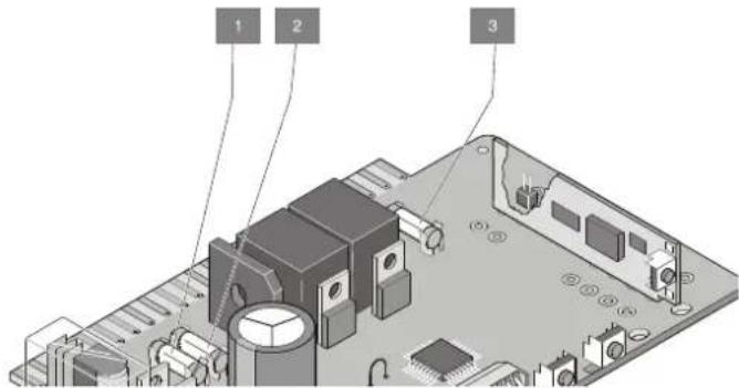
- Fuse for connection of warning lamp 1 terminal 16 + 17
- Fuse for connection of warning lamp 2, terminal 18 +19
- Fuse for 24 V connection, terminal 14 + 15
Additional Information
Disassembly

Observe safety instructions!
The sequence of procedures for disassembly corresponds to that described in chapter "Installation", whereby the instructions must be followed in reverse order. The setting procedures described are not applicable.
Disposal
Comply with applicable statutory regulations!
Warranty and After-Sales Service
The warranty complies with the statutory requirements. Claims under warranty must be made to your stockist. Warranty entitlements are limited to the country in which the drive has been purchased. Batteries, fuses and bulbs are not covered by warranty.
If you require after-sales service, spare parts or accessories, please contact your specialist stockist.
When compiling these installation and operating instructions, we have endeavoured to outline procedures and instructions as clearly and comprehensively as possible.
If you have any suggestions as to how this manual can be improved, or if you miss some information, please contact us by fax or e-mail:
Fax: +49 7021 8001-53
The most common defects and errors can be eliminated by following the instructions in the table below. If an error persists, contact your stockist or visit the "Forum" page on our website at http://www.sommer-torantriebe.de.
Fault/disruption Possible cause Remedy
| Gate cannot be opened or closed | Unit is not powered, LED “Power” is off | Check fuses and power supply linesActivate main switch Install control system |
| No control system installed | Replace fuse | |
| Fuse of circuit has triggered; LED “Power” is off | Check power supply by connecting a different device (e.g. power drill) | |
| Control system is not correctly installed | Ensure that the control unit is properly connected to the terminal strip | |
| Automatic close mode is activated | Gate closes automatically, after the set time has lapsed | |
| Light barrier has been triggered, LED “Safety” is on | Deactivate automatic close mode, turn potentiometer in anticlock-wise direction to the stop Remove obstacle in the light barrier | |
| Safety contact strip (8.2 kOhm) defective or DIP switch 2 set to OFF, LED “Safety” is on | Replace safety contact strip or set DIP switch 2 to ON | |
| Fraba system activated, while light barrier or safety contact strip (80.2 kOhm) is connected, LED “Safety” is on | Disable Fraba system, set DIP switch 6 to OFF | |
| Gate cannot be opened or closed by means of the hand-held transmitter or Funkcody | Battery empty, LED at hand-held transmitter is off | Replace battery |
| Teach-in of hand-held transmitter/Funkcody not completed | Teach in hand-held transmitter/Funkcody | |
| Incorrect radio frequency | Check frequency | |
| Signal is continuously transmitted, as the button is jammed; LED “Start” and LED at the receiver are on | Release button or replace hand-held transmitter/Funkcody | |
| Gate cannot be opened or closed by pressing the push-button/activating the key switch | Push-button not connected or defective LED “Start” is off while push-button is pressed | Check push-button connection or replace push-button |
| Continuous signal received - water in push-button housing; LED “Start” is on | Replace push-button and protect against the elements | |
| Gate stops during closing operation, moves approx. 10 cm in the opposite direction and stops | Force cut-off has been triggered by an obstacle | Remove obstacle, open gate fully |
| Incorrect force value, or force tolerance too small | Delete force values and repeat teach-in procedure; if the error persists, increase force tolerance value | |
| Switch trigger incorrectly positioned, gate moves to jam | Readjust position of switch trigger (see chapter “Positioning of Stops”) | |
| Gate settings incorrect, or gate defective | Contact specialist for readjustment or repair of gate | |
| Gate stops during opening operation, moves approx. 10 cm in the opposite direction and stops | Force cut-off has been triggered by an obstacle | Remove obstacle Close gate completely using the push-button |
| Incorrect force value, or force tolerance too small | Delete force values and repeat teach-in procedure; if the error persists, increase force tolerance value. Only possible with TorMinal, refer to TorMinal manual | |
| Switch trigger incorrectly positioned | Readjust position of switch trigger (see chapter “Positioning of Stops”) | |
| Gate stops during opening | Light barrier triggered and DIP switch 1 set to ON | Remove obstacle in light barrier or set DIP switch 1 to OFF |
| Drive fails to close the gate | Power supply to light barrier disrupted | Check power lineReplace fuse |
| Drive was disconnected from power supply | At the first command transmitted after the unit has been connected to the power supply, the gate always opens fully. | |
| Drive opens the gate, but no subsequent response to command from push-button or hand-held transmitter | System triggered through safety input (e.g. light barrier defective) | - Remove obstacle from light barrier |
| - Repair light barrier | ||
| LED “Safety” is on | - Control system not properly installed | |
| Connected warning lamp is off | Fuse defective | Replace fuse (see chapter “Maintenance and Servicing”) |
| Bulb defective | Replace bulb | |
| The gate moves at different speeds when opening/closing | Drive starts at normal speed, speed is reduced near the end position | No error; upon startup, the drive operates at maximum speed. Prior to reaching the end position, the speed is automatically reduced (soft run function). |
Troubleshooting
Fault/disruption Possible cause Remedy
| The gate can only be operated, as long as the button/key switch is pressed. The inside light is flashing (biased-off operation) | Biased-off mode activated | Deactivate biased-off mode (see TorMinal manual) |
| All LEDs at the radio receiver are flashing. | You appear to attempt to store more than 112 codes. |
Additional Tips for Troubleshooting
Should you be unable to identify and eliminate a fault using this table, please take the following steps:
- Disconnect any accessories (e.g. light barrier) connected to your system
- Reset all DIP switches to the default settings
- Reset all potentiometers to the default settings
- Carry out a reset of the control system (deletion of set force values)
- If settings have been changed with TorMinal, carry out a reset of the control system using TorMinal.
Spare Parts List

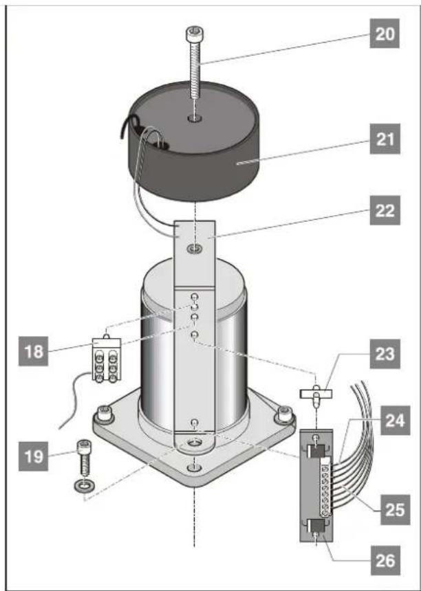
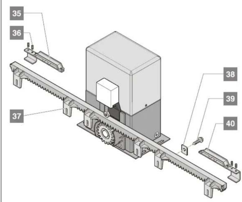
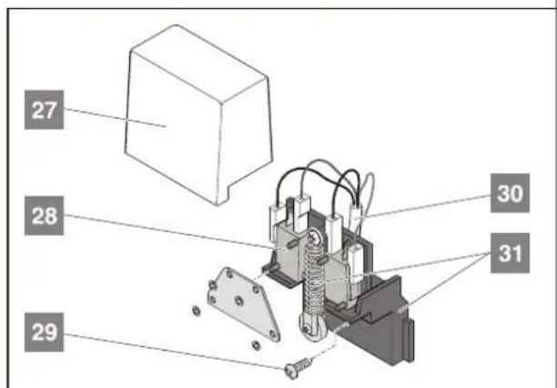
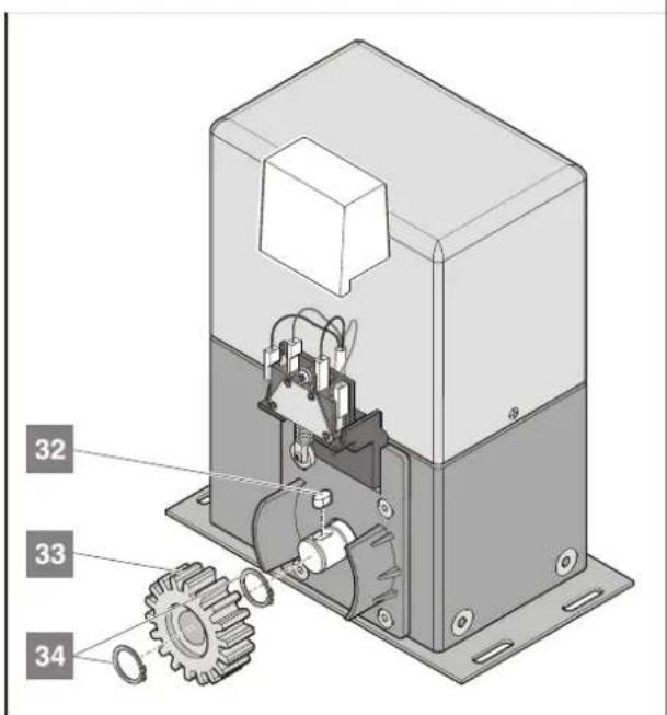
Spare Parts List
| Item no. | Description | Product no. | Quantity | Comment |
| 1 | C o v e | r - | 1 | |
| 2 Bracket for control system 12302 1 | ||||
| 3 Terminal bar, 24-pole 41007V001 1 | ||||
| 4 Control system 10507V300 1 including bracket with type plate | ||||
| 5 Screw M6 x 30 31123 1 | ||||
| 6 Screw set M 16 30015 4 | ||||
| Lock nut M16 30017 4 | ||||
| 7 | Motor-gear unit | - | 1 | without hood, transformer, control system and motor circuit board |
| 8 Screw | - | 4 | ||
| 9 Key | 5820-032V005 | 2 | ||
| 10 | Thread insert | - | 4 | |
| 11 | Anchor plate | 5820-070V000 | 1 | including item 10 |
| 12 | Screw 3.9 x 13 - | 2 | ||
| 13 | Screw M3 x 8 | 13518 2 | ||
| 14 | Screw connection M20 | 30016 1 | ||
| Lock nut M20 30018 1 | ||||
| 15 | Litz wire yellow/green | 12305 1 | ||
| 16 | Screw 4.2 x 13 10009 1 | |||
| 17 | Tooth-lock washer 6.2 | 31122 1 | ||
| 18 | Terminal, 3-pole | 12304 1 | ||
| 19 | Screw M6 x 30 31123 4 included in delivery of item 7 | |||
| 20 | Screw M5 x 55, DIN912 | 41067 1 | ||
| 21 | Transformer | 12309V000 1 | ||
| 22 | Bracket for transformer 12301 1 | |||
| 23 | Spacer | 12303 2 | ||
| 24 | Litz wire blue/black | 12307 1 | ||
| 25 | Litz wire blue | 12306 1 | ||
| 26 | Motor circuit board | 12227V000 1 | ||
| 27 | End switch cover | - | 1 | |
| 28 | End switch | - | 2 | |
| 29 | Screw | - | 1 | |
| 30 | Wiring harness end switch | - | 1 | |
| 31 | Bracket for end switch | - | 1 | including screw, castor and securing plate for end switch |
| 32 | Parallel key 8x7x15 | 5820-020 | 1 | |
| 33 | Toothed wheel module 4 | 5820-018 | 1 | |
| 34 | Seeger retaining ring 5820-019 | 2 | ||
| 35 | Switch trigger, right | - | 1 | |
| 36 | Setscrew M6 x 20 | - | 4 | |
| 37 | Rack, 1m | 5829 | 4 | including securing material items 38 + 39 |
| 38 | Washer | - | - | included in delivery of item 97 |
| 39 | Screw | - | - | included in delivery of item 97 |
| 40 | Switch trigger, left | - | 1 | |
Glossary
| Area of movement | Area through which the gate moves when operated; the gate might thereby collide with persons, animals or objects located in the area of movement. | |||
| Main closing edge | Edge of the gate wing whose position determines the opening width between the door stop (opposite closing edge) and the gate wing. | |||
| Secondary closing edge | All closing edges at the gate wing except the main closing edge and opposite closing edge | |||
| Force tolerance | Tolerance range of the programmed force; the drive might operate the gate with a force that is within this tolerance range. | |||
| Soft run | Movement at minimum drive speed. | |||
| Intermediate stop | If a command is issued while the gate is in motion (opening or closing), the drive is stopped. At the next command, the drive moves the gate in the opposite direction | |||
| TorMinal | Programming device that allows for the adjustment of all gate drives and the activation of special functions. |
Gate operators
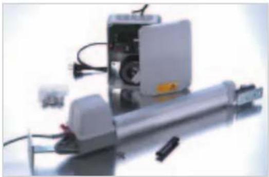
Swing gate operator twist 200 ...
natural_image
Exterior view of a mechanical device with visible internal components and wiring (no text or symbols)
natural_image
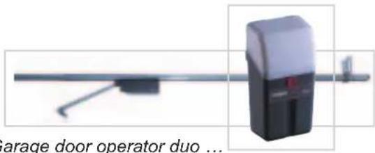
Simple line drawing of a long horizontal object with a small protrusion and a small rectangular base (no text or symbols)Garage door operators marathon /sprint ...
natural_image
Barage door operator duo device with mounted lever and control panel (no visible text or symbols)Radio technology
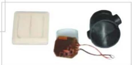
... Funkcody ...
natural_image
Three electronic components: a beige plastic case, a black circular device with wires, and a brown circuit board (no visible text or symbols)... Interior push-button ...
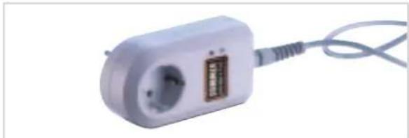
... Radio receiver with connecting cable ...
natural_image
White electrical plug with a socket and cable, isolated on white background (no text or symbols visible)Operators for roller shutters and awnings
natural_image
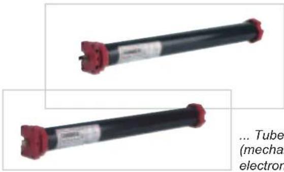
Two cylindrical electronic components with red connectors, labeled 'Tube (mechan electron)' (no other text or symbols visible)... Tube motors (mechanical or electronic end switches) ...
natural_image
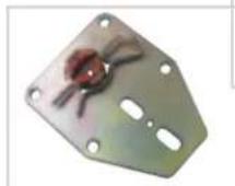
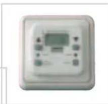
Front view of a white electronic device with control buttons and a central display (no visible text or symbols)... Control system ...
Accessories
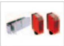
... Light barriers ...
natural_image
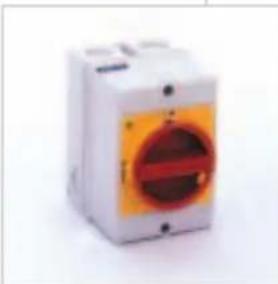
White electrical fuse box with orange button and red warning symbol (no text or labels visible)... Main switch ...
natural_image
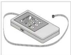
Illustration of a handheld electronic device with cables and a keypad (no text or symbols visible)... TorMinal ...
... Warning lamp, 24 V ...
natural_image
Close-up of a dark, semi-circular object with a yellowish top surface (no text or symbols visible)... and much more.
- starglider 300
- Contents
- General Tips 2
- General Instructions 4
- Installation 6
- Commissioning 9
- Operation 10
- Functions and Connections ..... 12
- Accessories 19
- Maintenance and Servicing....21
- Additional information....22
- Troubleshooting....23
- Spare Parts List 25
- General Tips
- Symbols
- Safety Instructions
- General
- Storage
- Operation
- for Radio Remote Control
- Rating Plate
- Normal Use
- Permitted Gate Dimensions
- Technical Data
- Dimensions
- EU Manufacturer's Declaration
- Preparations for Installation
- Scope of Delivery
- Complete drive package
- Individual drive
- Preparations of Installation
- Installation Tips
- General Preparation
- Installation
- Location of Installation
- Foundation
- Installation to Ground
- Procedure:
- Mounting of rack
- Positioning of Stops
- Connection to power supply
- Commissioning
- Teaching in of Drive
- Check force settings
- Teaching in of Hand-Held Transmitter
- Closing of Gate
- Default settings for all drives
- Reset of Control System
- Emergency Release
- Overload Protection
- Operation following a Power Failure
- Function of Button 2
- Intermediate Stop
- Stop forced by Obstacle
- Force cut-off
- Safety input 1 triggered e.g. due to activation of safety contact strip
- Safety input 2 triggered e.g. due to triggering of light barrier
- Functions and Connections
- General Information regarding : Control Settings
- DIP Switches 1 - 8
- Switch Position Function/response
- Radio Receiver Safety Instructions
- Deleting of Assigned Radio Codes
- Deleting of Channels
- Deleting all Data in Radio Receiver Memory
- Obstacle Detection (DIP 1, 2 + 3)
- Obstacle detected while gate is opening
- Force cut-off
- Safety input 1, terminal 6 + 7
- DIP switch 1:
- Safety input 2, terminal 8 +9
- Obstacle detected while gate is closing
- Safety input 1, terminal 6 +7
- DIP switch 3:
- Automatic Close Mode
- Example:
- Option 1: Automatic close mode
- Settings:
- Option 2: Automatic close mode + light barrier (DIP switch 4)
- Option 3: Automatic close mode + safety contact strip + light barrier
- Warning Time (DIP 5)
- DIP switch 5
- Fraba System (DIP 6)
- DIP switch 6
- Separate Signals for Closing and Opening (DIP Switch 7)
- DIP switch 7
- Partial Opening (DIP 8)
- DIP switch 8
- Partial opening by pressing 2 push-buttons
- Partial opening by means of
- hand-held transmitter (2-channel operation)
- Terminal Assignment/colour Connection/description
- Terminal Colour of cable Description
- Push-button 1
- Push-button 2
- Connection of Fraba System
- Connection of Safety contact strip
- V Connection
- Floating relay output
- Connection of External Antenna
- TorMinal Interface
- Special Functions
- Accessories
- Warning Lamp
- Key Switch
- Light Barrier
- Base frame
- Main Switch
- External Antenna
- Safety contact strip
- 8,2 kOhm
- Fraba system
- Maintenance and Servicing
- Important Information
- Regular Inspection
- Replacement of Fuses
- Additional Information
- Disassembly
- Disposal
- Warranty and After-Sales Service
- Troubleshooting
- Additional Tips for Troubleshooting
- Spare Parts List
- Gate operators
- Radio technology
- Operators for roller shutters and awnings
Brand : Sommer
Model : Starglider 300
Category : Garage door opener