GIGAline - Garage door opener Sommer - Free user manual and instructions
Find the device manual for free GIGAline Sommer in PDF.


| Product Type | Garage door opener (sectional door) |
| Model | Sommer GIGAline |
| Rated Voltage | AC 220–240 V |
| Rated Frequency | 50–60 Hz |
| Duty Cycle | S3 = 60% |
| Operating Temperature | -5°C to +60°C (GIGAheat required below -5°C) |
| Noise Emission | < 75 dB(A) |
| IP Protection Class | IP54 |
| Drive Torque | 100 Nm |
| Static Holding Torque | 450 Nm |
| Motor Output | 0.55 kW |
| Rated Power Consumption | 3.45 A |
| Max. Speed | 210 mm/s (80 Hz) |
| Max. Travel Length | 3060 mm (4160 mm with 1 extension) |
| Max. Door Weight | 500 kg |
| Max. Door Width/Height | 8000 mm x 3500 mm |
| Max. Number of Cycles | > 100 |
| Safety Features | Obstacle detection (reverses on contact), emergency release, photocell required, active safety contact strip required |
| Maintenance | Monthly: test emergency release, obstacle detection, photocell. Yearly: inspect door and moving parts |
| Warranty | Statutory warranty; valid only in country of purchase; no warranty for consumables |
| Intended Use | Opening and closing sectional garage doors; not for fire protection or emergency exits |
Frequently Asked Questions - GIGAline Sommer
User questions about GIGAline Sommer
0 question about this device. Answer the ones you know or ask your own.
Ask a new question about this device
Download the instructions for your Garage door opener in PDF format for free! Find your manual GIGAline - Sommer and take your electronic device back in hand. On this page are published all the documents necessary for the use of your device. GIGAline by Sommer.
USER MANUAL GIGAline Sommer
natural_image
Technical line drawing of a mechanical assembly with a long rod and mounting bracket (no text or symbols)EN TRANSLATION OF THE ORIGINAL INSTALLATION AND OPERATING MANUAL
Download the current manual:



This product has been developed and manufactured under high standards of quality and with reference to ISO 9001. Read this installation and operating manual carefully and follow all instructions.
Warranty
The warranty complies with statutory requirements. The contact person for warranties is the qualified dealer. The warranty is only valid in the country in which the operator was purchased. There is no warranty for consumables such as batteries, accumulators and fuses as well as light bulbs. This also applies for wear parts.
The operator is only designed for a limited frequency of use. More frequent use leads to increased wear.
Contact data
If you require after-sales service, spare parts or accessories, please contact your qualified specialist retailer or installer.
Service
If you require service, please contact us on our service hotline (fee required) or see our web site:

Copyright and proprietary rights
The manufacturer retains the copyright for this Installation and Operating manual. No part of this installation and operating manual may be reproduced in any form without the written permission of SOMMER Antriebs- und Funktechnik GmbH or processed, copied, or distributed using electronic systems. Violations of the specifications above will lead to claims for damages. All brands mentioned in this Installation and Operating Manual are the property of their respective manufacturer and hereby recognised as such.
1. About this Installation and Operating Manual 4
1.1 Storage and circulation of the Installation and Operating Manual 4
1.2 Important for translations 4
1.3 Description of the product type 4
1.4 Target groups of the Installation and Operating Manual 4
1.5 Explanation of symbols and notes 4
1.6 Information regarding the depiction of text 5
1.7 Intended use of the operator 5
1.8 Improper use of the operator 6
1.9 Qualifications of personnel 6
1.10 Instructing the user and handover of documents 6
1.11 Information for the user 6
2. General safety instructions 8
2.1 Basic safety instructions for operation 8
3. Description of function and product 10
3.1 The operator and its mode of operation 10
3.2 Safety equipment 10
3.3 Product designation 11
3.4 Tool symbols 11
3.5 Scope of delivery 12
3.6 Scope of delivery 14
3.7 Technical data 15
4. Installation 16
4.1 Required tools and personal protective equipment 16
4.2 Important notes and information 17
4.3 Preparing for installation 18
4.4 Installing the drive system 19
5. Electrical connection, initial operation 24
- Maintenance and care 25
6.1 Important notes and information 25
6.2 Maintenance schedule 26
6.3 Care 26
6.4 Cleaning the photocell 26
7. Taking out of operation, storage and disassembly 27
7.1 Important notes and information 27
7.2 Taking out of operation and disassembly 27
7.3 Storage 27
7.4 Disposal 28
8. Brief instructions for installation 29
1. About this Installation and Operating Manual
1.1 Storage and circulation of the Installation and Operating Manual
Read this Installation and Operating Manual carefully and completely before installation, commissioning and operation and also before removal. Observe all warnings and safety instructions.
Keep this Installation and Operating Manual accessible to all users at all times at the place of use. A replacement for the installation and operating manual can be downloaded from SOMMER at:
www.sommer.eu
During the transfer or resale of the operator to third parties, the following documents must be passed on to the new owner:
• EC Declaration of Conformity
- handover protocol and inspection book
- this Installation and Operating Manual
• proof of regular maintenance, testing and care
• documents recording retrofitting and repairs
1.2 Important for translations
The original installation and operating manual was written in German. The other available languages are translations of the German version. You can get the original installation and operating manual by scanning the QR code.

http://som4.me/orig-base-plus-revg
For other language versions, see:
www.sommer.eu
1.3 Description of the product type
The operator has been constructed according to state-of-the-art technology and recognised technical regulations and is subject to the Machinery Directive 2006/42/EC.
The operator is fitted with a radio receiver. Optionally available accessories are also described. The version can vary depending on the type. This means the use of accessories can vary.
1.4 Target groups of the Installation and Operating Manual
The installation and operating manual must be read and observed by everyone assigned with one of the following tasks or using the device:
- unloading and in-house transport
- unpacking and installation
- initial operation
- setting
- usage
- maintenance, testing and care
• troubleshooting and repairs
• disassembly and disposal
1.5 Explanation of symbols and notes
The warnings in this installation and operating manual are structured as follows.

Signal word

Hazard symbol
Type and source of hazard
Consequences of the hazard
▶ Preventing/avoiding the hazard
The hazard symbol indicates the hazard. The signal word is linked to a hazard symbol. The hazard is classified into three classes depending on its danger:
DANGER
WARNING
CAUTION
There are three different classifications of hazards.

DANGER

Describes an immediate danger that leads to serious injury or death.
Describes the consequences of the danger to you or other persons.
▶ Follow the instructions for avoiding or preventing the danger.

WARNING

Describes a potential danger that may lead to fatal or serious injury.
Describes the possible consequences of the danger to you or other persons.
▶ Follow the instructions for avoiding or preventing the danger.

CAUTION

Describes a potential danger of a hazardous situation.
Describes the possible consequences of the danger to you or other persons.
▶ Follow the instructions for avoiding or preventing the danger.
1. About this Installation and Operating Manual
The following symbols are used for notes and information:

NOTE
- Describes additional information and useful notes for correct use of the operator without endangering persons. If it is not observed, property damage or faults in the operator or door may occur.

INFORMATION
- Describes additional information and useful tips. Functions for optimum usage of the operator are described.
The following symbols are used in the figures and text.

Continue reading the Installation and Operating Manual for more information.

Disconnect the operator from the mains voltage

Connect the operator to the mains voltage

Factory setting, as-delivered state depending on version

Connection via SOMlink to a WiFi-enabled device

Operator components must be disposed of properly
1.6 Information regarding the depiction of text
- Stands for directions for an action
⇒ Stands for the results of the action
Lists are shown as a list of actions:"4.2 Important notes and information"
- List 1
- List 2
1, A Item number in the figure refers to a number in the text.
Important text items, for example in directions for actions, are emphasised in bold type.
References to other chapters or sections are in bold type and set in "quotation marks."
1.7 Intended use of the operator
The operator is intended exclusively to open and close doors. Any other use does not constitute intended use. The manufacturer accepts no liability for damage resulting from use other than intended use. The user bears the sole responsibility for any risk involved. It also voids the warranty.
Any changes to the operator must be made with original accessories from SOMMER only and only to the extent described. For more information on accessories, see:

https://downloads.sommer.eu/
1. About this Installation and Operating Manual
Doors automated with this operator must comply with all valid international and domestic standards, directives and regulations in their currently valid version. These include EN 12604 and EN 13241-1.
The operator may only be used:
- in combination with door types in the reference list which can be found at:

http://som4.me/cgdo
- if the EC Declaration of Conformity has been issued for the door system
- if the CE mark and the type plate for the door system have been attached to the door
- if the handover protocol and the inspection book have been completed and are available
- if the installation and operating manuals for the operator and the door are present
• as specified in this Installation and Operating Manual
• in good technical condition - with attention to safety and hazards by trained users.
After installation of the operator, the person responsible for the installation of the operator must complete an EC Declaration of Conformity for the door system in accordance with Machinery Directive 2006/42/EC and apply the CE mark and a type plate to the door system. This also applies if the operator is retrofitted to a manually operated door. In addition, a handover protocol and an inspection book must be completed.
The following are available:
• EC Declaration of Conformity
- handover protocol for the operator

http://som4.me/konform
1.8 Improper use of the operator
Any other use or additional use that has not been described in Chapter 1.8 constitutes improper use. The user bears the sole responsibility for any risk involved.
The manufacturer's warranty will be voided by:
- damage caused by other use and improper use
- use with defective parts
- unauthorised modifications to the operator
- modifications and non-approved programming of the operator and its components
The door must not be part of a fire protection system, an escape route or an emergency exit that automatically
closes the door in the event of fire. Installation of the operator will prevent automatic closing.
Observe the local building regulations.
The operator may not be used in:
- areas with explosion hazard
- very salty air
• aggressive atmosphere, including chlorine
1.9 Qualifications of personnel
Qualified specialist for installation, commissioning and disassembly
This Installation and Operating Manual must be read and complied with by a qualified specialist who installs or performs maintenance on the operator.
Work on the electrical system and live parts may only be performed by a trained electrician in accordance with EN 50110-1.
The installation, initial operation and disassembly of the operator may only be performed by a qualified specialist. A qualified specialist is a person commissioned by the installer.
The qualified specialist must be familiar with the following standards:
• EN 13241-1 Doors and gates – Product standard
- EN 12604 Doors and gates – Mechanical aspects – Requirements and test methods
• EN 12453: Safety in use of power-operated doors 2022 (Plc)
When all work has been completed, the qualified specialist must:
- issue an EC Declaration of Conformity
- attach the CE mark and the type plate to the door system
1.10 Instructing the user and handover of documents
The qualified specialist must instruct the user:
• on the operation of the operator and its dangers
• on the handling of the manual emergency release
- on regular maintenance, testing and care which the user can carry out
The qualified specialist must inform the user which work may only be carried out by a qualified specialist:
- installation of accessories
- settings
• regular maintenance, testing and care - Troubleshooting
1.11 Information for the user
The user must ensure that the CE mark and the type plate have been attached to the door system.
The following documents for the door system must be handed over to the user:
1. About this Installation and Operating Manual
• EC Declaration of Conformity
- handover protocol and inspection book
- the installation and operating manuals for the operator and the door
The user is responsible for:
- keeping this Installation and Operating Manual accessible at all times at the place of use
• the intended use of the operator
• ensuring that the operator is in good condition - instructing all users how to use the operator, the hazards involved and in the operation of the emergency release
- operation
• regular maintenance, testing and care - Troubleshooting
The operator must not be used by persons with restricted physical, sensory or mental capacity or who lack experience and knowledge. All users must be specially instructed and have read and understood the Installation and Operating Manual.
Children must never play with or use the operator, even under supervision. Children must be kept clear of the operator. Handheld transmitters or other command devices must never be given to children. Handheld transmitters must be safely stored and protected against unintended and unauthorised use.
The user must observe the accident prevention regulations and the applicable standards. The guideline "Technical regulations for workplaces ASR A1.7" of the German committee for workplaces (ASTA) is applicable for commercial use. The guidelines described must be observed and complied with. In other countries, the user must comply with the applicable national regulations.
2.1 Basic safety instructions for operation
Observe the basic safety instructions listed below, in as far as they are relevant for the specific system.
The control unit must not be used by persons with restricted physical, sensory or mental capacity or who lack experience and knowledge. All users must be specially instructed and have read and understood the installation and operating instructions. Persons under the influence of drugs, alcohol, or medications that can influence their ability to react may not work on the control unit. Children must never play with or use the control unit, even under supervision. Children must be kept clear of the control unit. Handheld transmitters or other command devices must never be given to children. Handheld transmitters and other command devices must be stored in such a way that unauthorised or accidental operation is prevented.
Danger if not observed!
Serious injury or death may result if safety instructions are not observed.
It is imperative to comply with all safety instructions!
Danger due to electric current!
Contact with live parts may result in electric current flowing through the body. Electric shock, burns, or death may result.
▶ Installation, testing and replacement of electrical components must be carried out by trained electricians.
▶ Disconnect the mains plug before working on the system.
▶ If an accumulator is connected, it must also be disconnected from the control unit.
▶ Check that the system is disconnected from the voltage supply.
- Secure the system against being switched back on.
Danger due to use of the system with incorrect settings or when it is in need of repair!
If the system is used despite incorrect settings or if it is in need of repair, severe injury or death may result.
The system may only be used with the required settings and in the proper condition.
▶ Inspect the system frequently for indications of wear, damage or defective weight balancing.
Following installation and thereafter at monthly intervals, check that the operator reverses upon contacting a 40 mm high object on the floor (obstacle recognition).
▶ Faults, worn components or defects in the weight balance must be repaired professionally without delay.
Danger caused by hazardous substances!
Improper storage, use or disposal of accumulators, batteries and components of the system are dangerous for the health of humans and animals.
- Store accumulators and batteries out of the reach of children and animals.
- Keep batteries and accumulators away from chemical and thermal influences.
▶ Do not recharge batteries and defective accumulators.
▶ All components of the operator, including old accumulators and batteries, must be disposed of correctly and not with household waste.
Danger for trapped persons!
Persons may be trapped inside the garage. If trapped persons cannot free themselves, severe injury or death may result.
▶ Check the function of the emergency release at monthly intervals, particularly from inside in the door CLOSE end position and if necessary, also from the outside.
▶ Ensure that the emergency release is installed at a height of no more than 1.8 m.
▶ Attach an information sign in a prominent, clearly visible position near the emergency release lever.
▶ Have faults repaired professionally without delay.
Danger due to parts projecting into publicly accessible areas!
No parts should project into public footpaths or roads. This also applies while the door is moving. Persons and animals may be seriously injured.
- Keep public roads or footpaths free of obstacles.
Danger due to falling parts of doors!
Actuating the emergency release can lead to uncontrolled door movement if:
- springs are weakened or broken.
▶ the door has not been optimally weight-balanced.
Falling parts may cause a hazard. Severe injuries or death may result.
▶ Check the weight balance of the door at regular intervals.
▶ Pay attention to the movement of the door when the emergency release is actuated.
▶ Keep clear of the movement area of the door.
Danger of entrapment!
Persons or animals in the movement area of the door may be trapped and pulled along with the door. Severe or fatal injuries may result.
▶ Keep clear of the movement area of the door.
Before installation, remove all ropes or chains which are not required and disable all devices not needed for operation, for example blocks.
Danger of crushing and shearing!
If the door moves and there are persons or animals in the movement area, crushing and shearing injuries may be caused by the mechanism and safety edges of the door.
Before mounting the operator on the door, make sure that the door is in good mechanical condition, is optimally weight-balanced and opens and closes correctly.
▶ Only use the system when you have a direct view of the door.
The danger zone must be visible during the entire door operation.
▶ Always keep the moving door in sight.
- Keep persons and animals away from the movement area of the door.
▶ Never put your hand near the door when it is moving or near moving parts. In particular, do not reach into the moving push arm.
▶ Do not touch the ceiling suspension unit when the motor carriage is running past the ceiling suspension unit.
Do not drive through the door until it has opened completely.
▶ Never stand under the opened door.
▶ Attach warning signs in a prominent, clearly visible position near the fixed operating device.
▶ An active safety contact strip must be attached as a safety edge.
Danger caused by the door falling!
The door can drop in an uncontrolled manner if a support fails. Severe or fatal injuries may result.
▶ A suitable device (external safety catch, locking mechanism etc.) must be installed on-site.
Danger of falling!
Unsafe or defective ladders may tip and cause serious or fatal accidents.
▶ Use only a non-slip, stable ladder.
▶ Ensure that ladders are safely positioned.
Danger of tripping and falling!
Unsafely positioned parts such as packaging, operator parts or tools may cause persons to trip or fall.
- Keep the installation area free of unneeded items.
Place all parts where no-one is likely to trip or fall over them.
▶ Observe the general workplace guidelines.
Danger due to optical radiation!
Looking into the beam of a bright LED for prolonged periods can cause temporary irritation of the eyes. Serious or fatal accidents can occur as a result.
▶ Never look directly into the LED.
Risk of eye injury!
Chips flying when drilling may cause serious injuries to eyes and hands.
▶ Always wear safety glasses when drilling.
Risk of hand injury!
Rough metal parts may cause abrasions and cuts when picked up or touched.
▶ Wear safety gloves when performing tasks such as deburring.
Risk of injury in the head region!
Impact with suspended objects may cause serious abrasions and cuts.
▶ Wear a safety helmet when installing suspended parts.
Additional safety information for the radio remote control Danger of crushing and shearing!
If the door is not visible and the radio control is operated, crushing and shearing injuries to persons or animals may be caused by the mechanism and safety edges of the door.
In particular when operating control elements such as the radio remote control, all danger zones must be visible during the entire door operation.
▶ Before operating the handheld transmitter, check that the springs of the door are not weakened or broken.
▶ Always keep the moving door in sight.
- Keep persons and animals clear of the range of movement of the door.
▶ Never put your hand near the door when it is moving or near moving parts.
▶ Do not drive through the door until it has been fully opened.
- Store handheld transmitters so that unauthorised or accidental operation, e.g. by children or animals, is impossible.
▶ Operating devices in a fixed position (e.g. ext. buttons, key switches etc.) must be attached at a height of no more than 1.5 m and at a distance from moving parts.
▶ Never stand under the opened door.
Notes and information on operation and remote control
The user of the radio system is not protected against interference due to other telecommunications equipment or devices. This includes radio-controlled systems that are licensed to operate in the same frequency range. If significant interference occurs, please contact your appropriate telecommunications office which has radio interference measuring equipment or radio location equipment.

NOTE
If the door is not in view and the radio remote control is actuated, objects in the movement area of the door may be jammed and damaged.
▶ Objects must not be in the range of movement of the door.
▶ Only use the operator if you have a direct view of the door.
3. Description of function and product
3.1 The operator and its mode of operation
natural_image
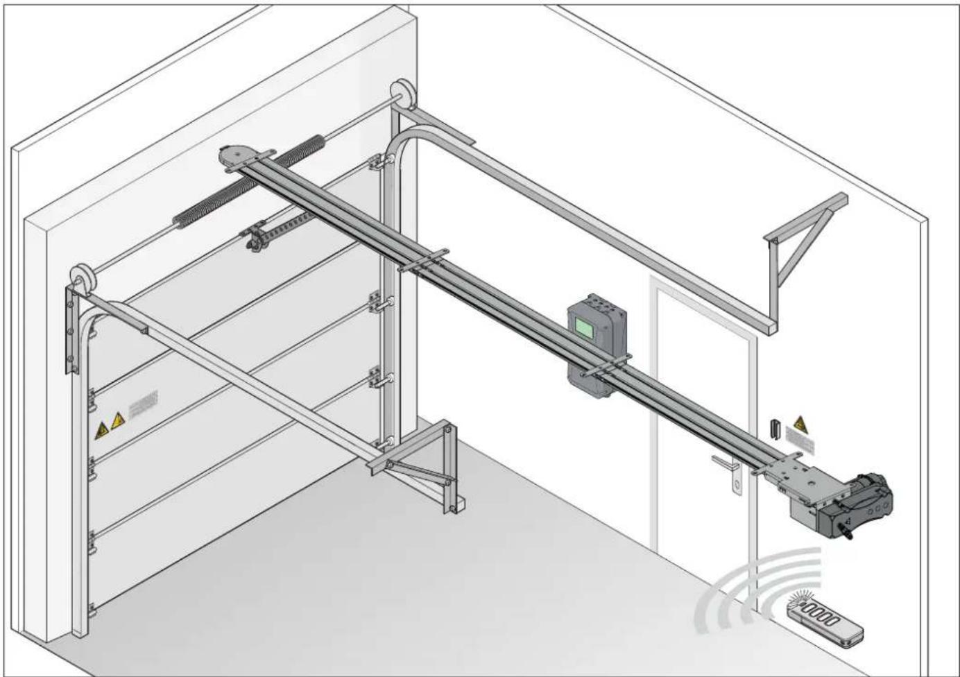
Technical line drawing of a mechanical assembly with no visible text or symbolsFig. Door structure with operator, using the example of a sectional door
Sectional doors can be opened and closed with the electrically powered operator and its available accessories. The operator can be controlled with a handheld transmitter.
The rail is mounted on the ceiling and the lintel above the garage door. The motor carriage is attached to the door by a push arm. The motor carriage moves along the rail on a spring-mounted chain and opens or closes the door. The handheld transmitter can be stored in a holder in the garage or in the vehicle. Handheld transmitters are not included in the scope of delivery.
3.2 Safety equipment
The operator stops and reverses slightly if it encounters an obstacle. This prevents injury and damage to property. The door will be partially or completely opened, depending on the setting.
In the event of a power failure, the door can be opened manually using an emergency release handle.
Active safety contact strips are required. The operator has no obstacle recognition.
3. Description of function and product
3.3 Product designation
natural_image
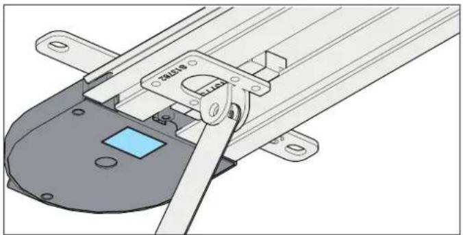
Technical illustration of a mechanical assembly with no visible text or symbolsThe type plate is included in the scope of delivery and must be attached by the technician/user after installation.
The type plate includes:
- type designation
- Item Number
• date of manufacture with month and year - serial number
In case of questions or service, please supply the type designation, the date of manufacture and the serial number. Explanation of tool symbols
3.4 Tool symbols
These symbols refer to the use of tools required for installation.


Phillips screwdriver


Flat head screwdriver


Metal drill
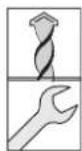

Masonry drill
Open-end wrench


Ratchet wrench
Other symbols

Drilling depth

Audible engaging or clicking noise
3. Description of function and product
3.5 Scope of delivery
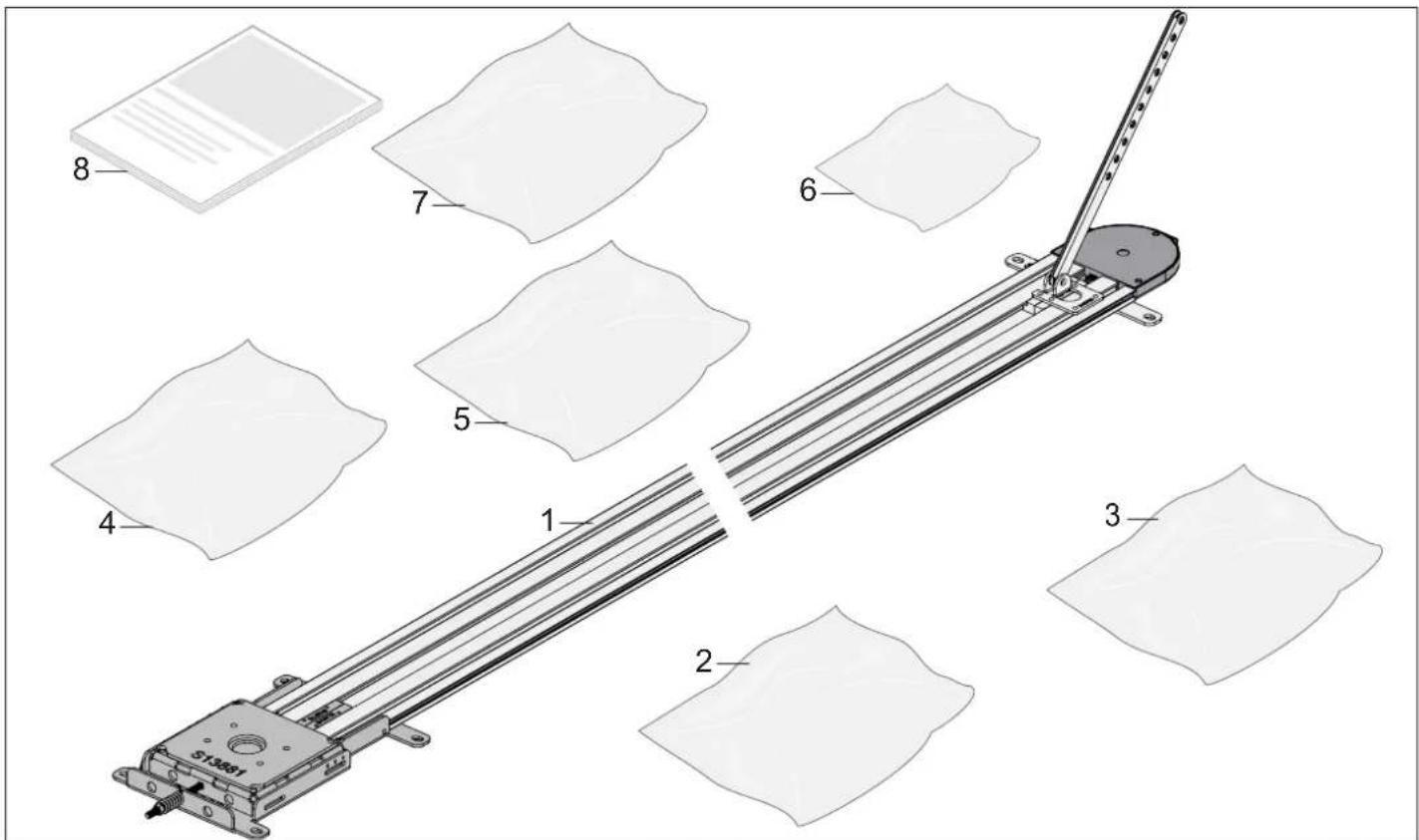
| Designation Quantity Designation Quantity | |||
| (1) GIGAline 1 (4) Installation bag 1 | |||
| Chain guide rails (aluminium) including plastic chain guide profile | 3 Screw, hexagon head M8 x 20 7 | ||
| Roller chain 1 Carriage bolt M8 x 95 1 | |||
| Carrier, push arm 1 Hexagon nut M8 1 | |||
| Grub screw, slot M8 x 16 4 | |||
| Motor support cover | 1 Washer d8.4 x d20 | 2 | |
| Motor support | 1 Master link | 2 | |
| Slide bearing | 1 Bolt with head | 1 | |
| Intermediate plate, motor | 1 Circlip, shaft | 1 | |
| Push arm for door panel | 2 Wall plug SFH 10 x 50 | 4 | |
| Bracket for door set | 1 Screw, hexagon head M8 x 60 4 | ||
| (2) Installation bag, deflection | Washer d8.4 x d20 | 4 | |
| Lower section, deflection | 1 | Screw M6 x 14 | 4 |
| Screw-on shaft, deflection | 1 | Slot nut with thread 91 x 12 x 5 | 4 |
| Screw M8 x 20 | 1 Screw M6 x 12 | ||
| Deflection pulley | 1 | (5) Installation bag, drive shaft | 1 |
| Cover, deflection | 1 | Drive sprocket, motor | 1 |
| Screw M6 x 12 | 4 Key 16 x 8 x 7 | 1 | |
| (3) Installation bag, slot nut set 2 Motor shaft | 1 | ||
| Slot nut, interior with thread | 4 Key 6.35 x 105 x 6.35 | 1 | |
| Slot nut, exterior | 4 Circlip, shaft | 1 | |
| Screw, hexagon head M6 x 10 | 16 | Washer d8.4 x d40 | 1 |
| Screw, hexagon head M8 x 20 1 | |||
3. Description of function and product
| Designation Quantity(6) Installation bag, ceiling bracket 3 | |
| Ceiling attachment 1 | |
| Screw M6 x 12 2 | |
| Slot nut 2 | |
| Wall plug 2 | |
| Screw M8 x 60 2 | |
| Washer 2 | |
| (7) Installation bag, door fitting 1 piece | |
| Door bracket 1 | |
| Screw, hexagon head, self-tapping 6.5 x 16 4 | |
| Bolt 1 | |
| Circlip with shaft 1 | |
| (8) Translation of the Installation and Operating Manual 1 |
- Description of function and product
3.6 Scope of delivery
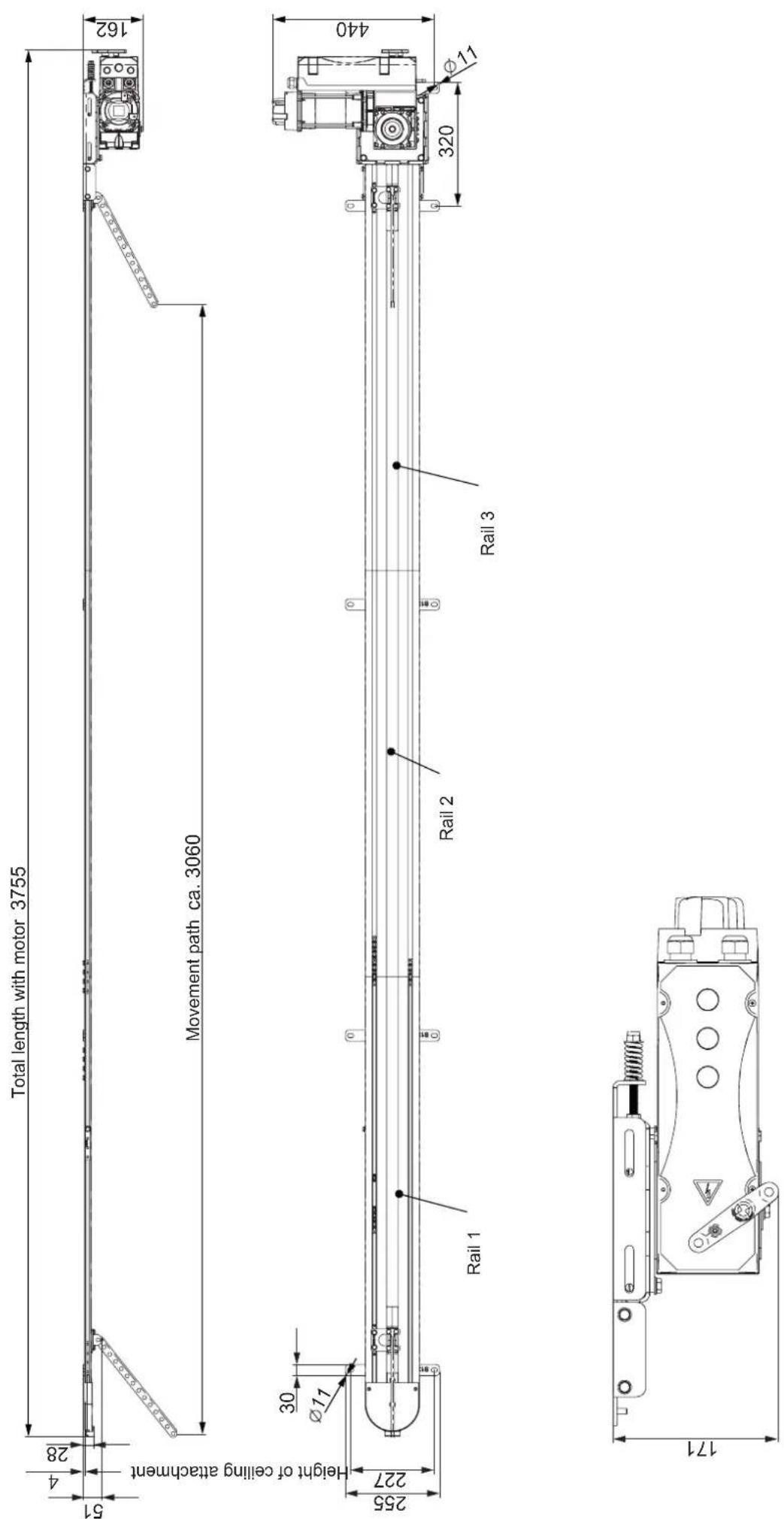
3. Description of function and product
3.7 Technical data
GIGAsedo 0.24.100 DXFS0 (FC)
| Rated voltage AC 220–240 V | |
| Rated frequency 50–60 Hz | |
| Duty cycle S3 = 60% | |
| Operating temperature* | -5^ to +60^ |
| Emission value according to operating environment | <75 dB(A) |
| IP protection class IP54 | |
| Drive torque 100 Nm | |
| Static holding torque 450 Nm | |
| Motor output 0.55 Kw | |
| Limit stop range** 14 | |
| Rated power consumption 3.45 A | |
| Operator speed 10–35 rpm | |
| Max. speed 210 mm/s (80Hz) | |
| of hollow shaft 25.4 mm | |
| Max. travel length | 3060 mm |
| Max. travel length incl. 1 extension | 4160 mm(1 x 1100 mm) |
| Max. door weight | 500 kg |
| Max. door width/door height*** | 8000 mm x 3500 mm |
| Max. no. of spaces | >100 |
* GIGAheat (S10750-00002) required at <5 °C
** with E14 max. lift of 4200 mm, other motor required or KOSTAL gearing (S12421-00001) required
*** Extension S14006-00001 required
Door types and accessories
Door type Accessories
Sectional door
4. Installation
4.1 Required tools and personal protective equipment
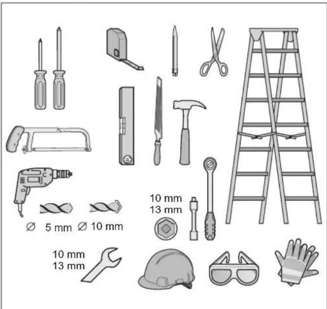
Fig. Recommended tools and personal protective equipment for installation
You will require the tools shown above to assemble and install the operator. Lay out the required tools beforehand to ensure fast and safe installation.
Wear your personal protective equipment. This includes safety glasses, safety gloves and a safety helmet.
4.2 Important notes and information
In particular, please observe and comply with the following warnings, notes and information to ensure safe installation.

DANGER

Danger if not observed!
If warnings are not observed, serious injury or death may result.
▶ All warnings must be complied with.

WARNING

Danger of falling!
Unsafe or defective ladders may tip and cause serious or fatal accidents.
▶ Use only a non-slip, stable ladder.
▶ Ensure that ladders are safely positioned.

Danger for trapped persons!
Persons may be trapped inside the garage. If trapped persons cannot free themselves, severe injury or death may result.
▶ Check the function of the emergency release at monthly intervals, particularly from inside in the door CLOSE end position and if necessary, also from outside.
If there is no second entrance to the garage, you must have a release lock or a Bowden wire for unlocking from the outside installed. This can be used to free persons who cannot free themselves.

Danger due to projecting parts!
Door leaves or other parts must not project into roads or public footpaths. This also applies while the door is moving. This may cause serious injury or death to persons or animals.
▶ Keep public roads and footpaths clear of projecting parts.

Danger due to falling parts of doors!
If a door is incorrectly balanced, springs may break suddenly. Falling door parts may cause serious injury or death.
Check:
▶ the stability of the door.
▶ that the door does not bend, rotate or twist when you open or close it.
▶ that the door runs smoothly in the rails.

Danger due to falling ceiling and wall parts!
The operator cannot be installed correctly if ceiling and walls are unstable or if unsuitable mounting materials are used. Persons or animals may be struck by falling parts of the wall, ceiling or operator. Severe injuries or death may result.
▶ You must test the stability of the ceiling and the walls.
▶ Use only permissible mounting materials appropriate for the supporting surface.

Danger of entrapment!
Loose clothing or long hair may be trapped by moving parts of the door. Severe injuries or death may result.
▶ Keep clear of the moving door.
▶ Always wear tight-fitting clothing.
▶ Wear a hairnet if you have long hair.

Danger of crushing and shearing!
If the door moves and there are persons or animals in the movement area, crushing and shearing injuries may be caused by the mechanism and safety edges of the door.
▶ Only use the operator when you have a direct view of the door.
▶ All danger zones must be visible during the entire door operation.
▶ Always keep the moving door in sight.
▶ Keep persons and animals clear of the range of movement of the door.
▶ Never put your hand near the door when it is moving or near moving parts. In particular, do not reach into the moving push arm.
▶ Do not reach into the ceiling suspension unit when the motor carriage is running along the rail.
▶ Do not drive through the door until it has opened completely.
▶ Never stand under the opened door.

Danger of tripping and falling!
Unsafely positioned parts such as packaging, operator parts or tools may cause trips or falls.
- Keep the installation area free of unnecessary items.
Place all parts where no-one is likely to trip or fall over them.
The general workplace guidelines must be observed.

Risk of eye injury!
Chips flying when drilling may cause serious injuries to eyes and hands.
▶ Wear safety glasses when drilling.

Risk of injury in the head region
Impact with suspended objects may cause serious abrasions and cuts.
▶ You must wear a safety helmet when installing suspended parts.

CAUTION

Risk of injury to hands!
Rough metal parts may cause abrasions and cuts when picked up or touched.
▶ Wear safety gloves when deburring or performing similar work.

NOTE
- If the ceiling and walls are not stable, parts of the ceiling and wall or the operator may fall. Objects may be damaged.
Ceiling and walls must be stable.
- To prevent damage to the door or operator, use only approved mounting materials such as wall plugs or screws.
The mounting material must be suitable for the material of the ceiling and walls. This applies particularly for pre-fabricated garages.
4.3 Preparing for installation
Before installation, you must check whether the operator is suitable for the door, see also Chapter ""3.7 Technical data""
Removal of actuation parts

WARNING

Danger of entrapment!
Persons or animals may be trapped by straps or cords and pulled into the movement zone of the door. Severe injuries or death may result.
▶ Remove straps and cords used for mechanical actuation of the door.
Before installation, remove:
- manual locking on door
- all cords or straps necessary to operate the door by hand.
Disabling mechanical locks
The mechanical lock on a door with an operator must be removed or disabled if it is not compatible with the operator.

NOTE
- If locks or other locking systems are installed on a mechanical door, they may block the operator. This may cause faults or damage to the operator.
- Before the installation of the operator, all mechanical locking systems must be disabled.
Checking the mechanism and weight balance

WARNING

Danger due to falling parts of doors or complete door panels!
Wires, spring sets and other fittings can be damaged and break. The complete door panel can fall.
Persons or animals may be struck by falling parts of the door or the complete door panel. Severe injuries or death may result.
Before installation, a qualified specialist must check and, if necessary, adjust the following:
▶ wires, spring sets and other fittings of the door.
▶ the weight balance of the door.

WARNING

Danger of entrapment!
If the force setting is too high, persons or animals in the movement area of the door may be trapped and pulled along with the door. Severe injuries or death may result.
The force setting is relevant to safety and must be carried out by a qualified specialist.
▶ You must proceed with extreme caution if you check and if necessary adjust the force setting.

NOTE
- If the weight compensation of the door is incorrectly adjusted, the operator may be damaged.
— The door must be stable.
— It must not bend, rotate or twist when opening and closing.
— The door must move easily in the rails.
- Check the mechanisms of the door, such as cables, spring sets and other fittings.
4. Installation
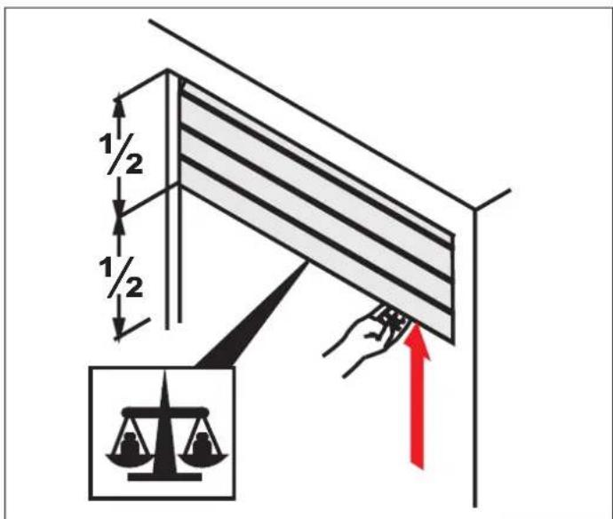
Fig. 2
- Open the door halfway.
⇒ The door must remain in this position.
⇒ The door must be moved easily by hand and must be balanced.
If the door moves upwards or downwards by itself, the weight balance of the door must be adjusted.
Emergency release
- Emergency release is only possible directly at the operator.
• A further access is essential. - A solution with a Bowden wire or release lock is not possible.

INFORMATION
- The emergency release must be easy to operate in all necessary positions.
- In particular, unlocking must be possible in door CLOSE.
4.4 Installing the drive system
The operator may only be installed if the installation requirements and dimensions below are correct.

NOTE
- Specify the position for mounting the operator on the door. Manually open and close the door several times. The door must be moved easily. A manual movement force of 150 N is applicable for private garage doors and 260 N for commercial doors. The value is applicable for the entire life of the door. The door must also be maintained and inspected as specified by the door manufacturer.

INFORMATION
- Before installation, check whether the garage is suitable for the operating temperature indicated on the control unit.
- Open the package.
Place the contents of the package beside the rails and open them.
Check the entire contents against the scope of delivery, see Chapter "3.5 Scope of delivery".
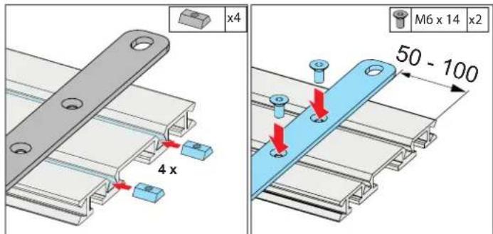
Fig. 2 Fig. 3
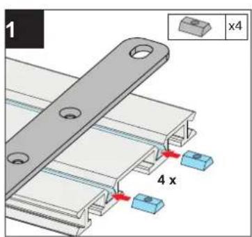
- Feed the slot nuts for ceiling attachment into the profile rail.
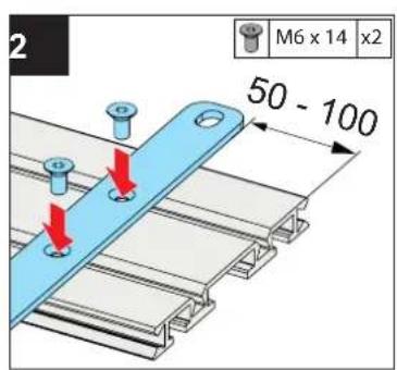
- Position and screw on the ceiling bracket in the immediate vicinity of the rail connection (distance 50–100 mm).
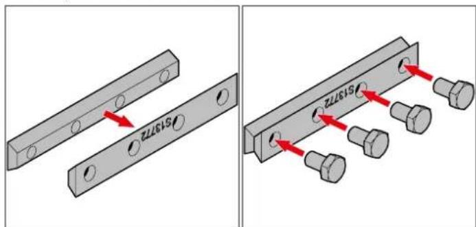
Fig. 4 Fig. 5
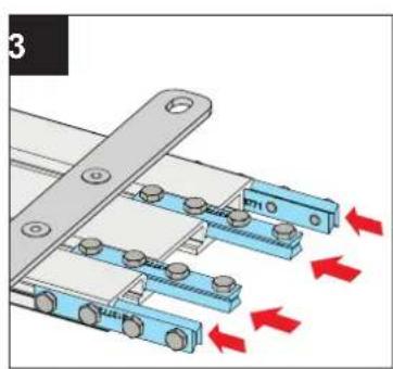
- Place the slot nuts (interior and exterior) together.
- Fit screws by hand so that the slot nuts are loosely connected.
⇒ Created element: rail connector
4. Installation
natural_image
Mechanical assembly diagram showing two views of a rail-mounted frame with mounting brackets and red directional arrows indicating motion (no text or symbols present)Fig. 6 Fig. 7
natural_image
Pure mechanical component diagram showing a long horizontal bar with four end caps (no text or symbols)Fig. 8
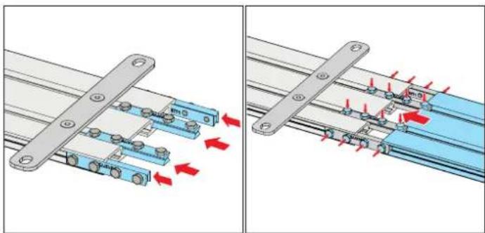
- Feed the rail connectors into the profile rail.
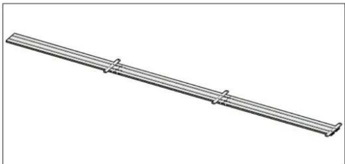
- Fit further profile rail and tighten the screws of the rail connectors.
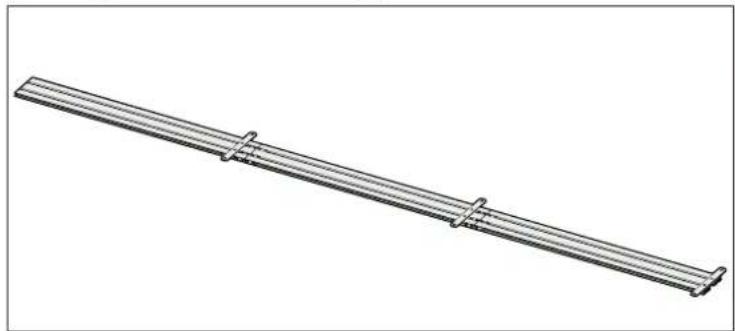
- Proceed in the same way, connecting all profile rails to form a complete track.
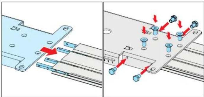
natural_image
Mechanical assembly diagram showing a metal bracket being inserted into a rail track with red arrows indicating force or movement (no text or symbols present)Fig. 9 Fig. 10
-
Feed further slot nuts (interior with thread) into the rear section of the track and fit the motor support for screw-mounting.
-
Slide motor support on as far as the stop and screw it tight.
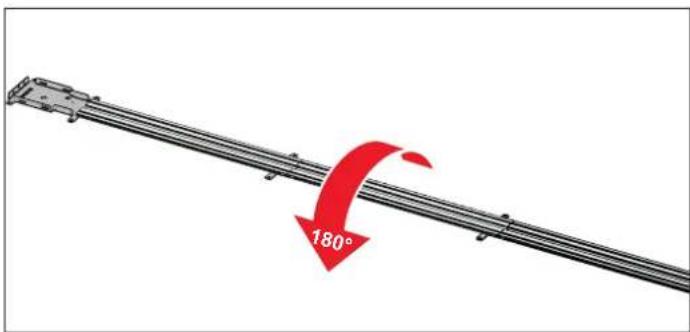
Fig. 11
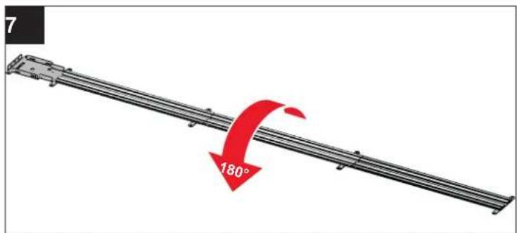
- Turn track unit through 180^ .
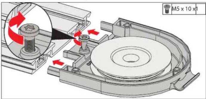
Fig. 12
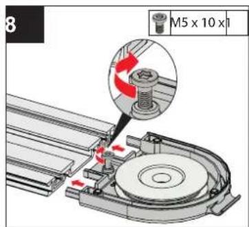
- Feed deflection assembly for chain into the front section of the track unit and screw it tight.
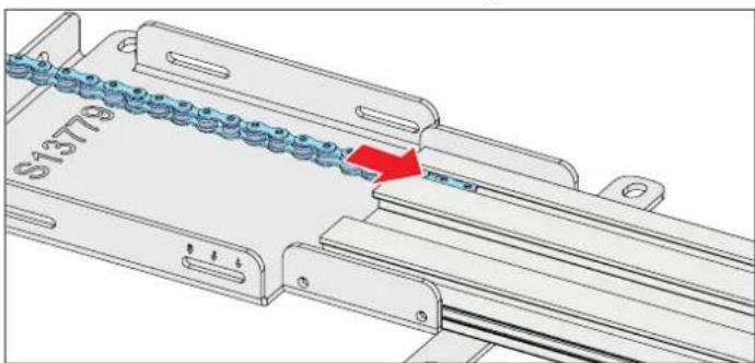
natural_image
Mechanical assembly diagram showing a chain of blue components mounted on a metal frame, with a red arrow indicating direction (no text or symbols present)Fig. 13
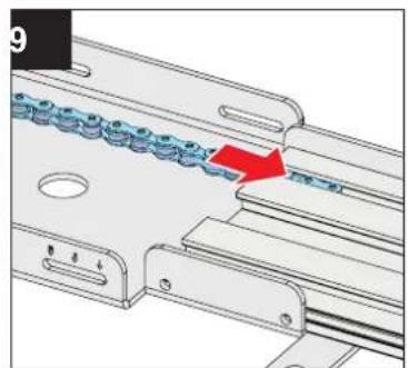
- Feed the chain into the chain guide profile of the track unit.
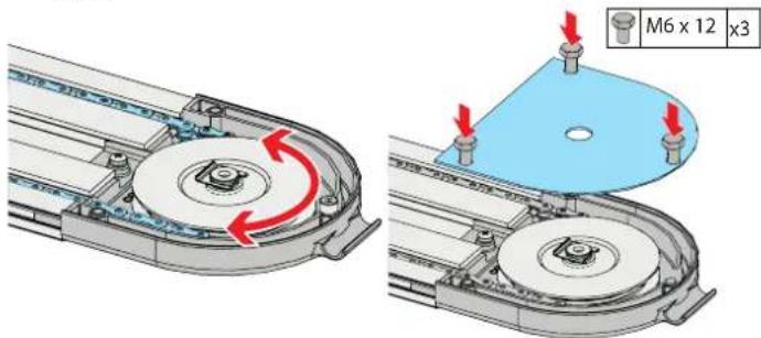
Fig. 14 Fig. 15
- Route the chain around the deflection pulley.
- Place the cover on the deflection assembly and screw it tight.
4. Installation
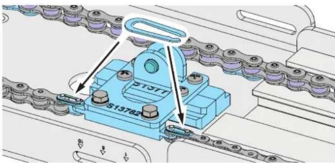
Fig. 16
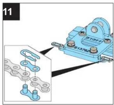
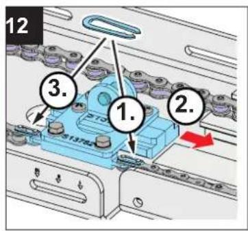
- Connect the carrier to the chain using the master links.
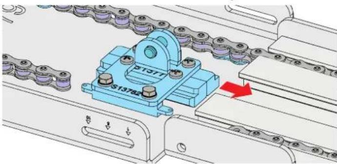
natural_image
Mechanical assembly diagram showing a blue S13782 chain clamp mechanism with a red arrow indicating motion (no text or symbols present)Fig. 17
- Feed the carrier into the track unit.
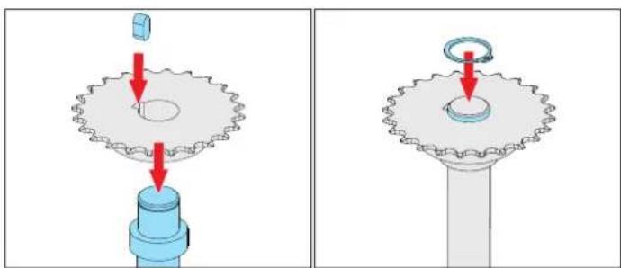
natural_image
Mechanical gear assembly diagram showing two stages of tool positioning (no text or symbols)Fig. 18 Fig. 19
-
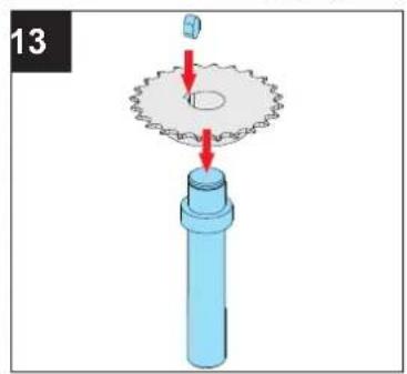
Place the sprocket on the motor shaft and insert the key.
-
Fix sprocket in position on the motor shaft using a KL lock.
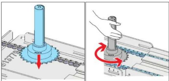
Fig. 20 Fig. 21
-
Insert sprocket and drive shaft into the motor support between the revolving chain.
-
Turn the motor shaft to ensure that the pinion engages correctly in the links of the chain and that the chain can be moved.
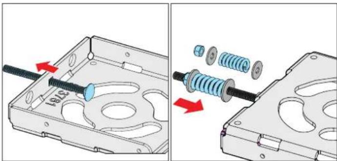
natural_image
Mechanical assembly diagram showing a component being inserted into a hard drive (no text or symbols present)Fig. 22 Fig. 23
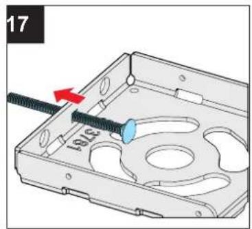
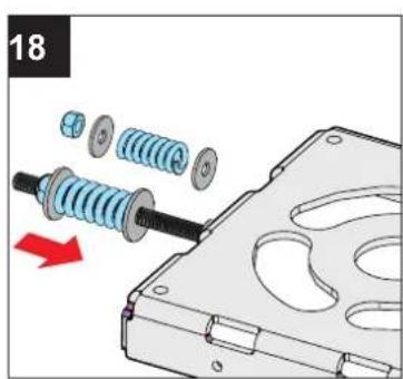
-
Insert the carriage bolt into the cover of the motor support.
-
Set up the spring tensioning element as shown.
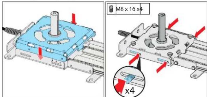
Fig. 24 Fig. 25
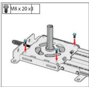
Fig. 26
-
Place the cover of the motor support on the motor support.
-
Screw motor support and cover together using grub screws.
-
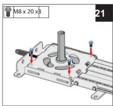
Screw the screws for later suspension of the operator into the cover of the motor support as shown.
4. Installation
natural_image
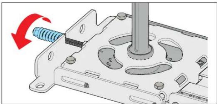
Mechanical assembly diagram showing a screw being inserted into a housing with a rotating arrow indicating rotation (no text or symbols present)Fig. 27 A
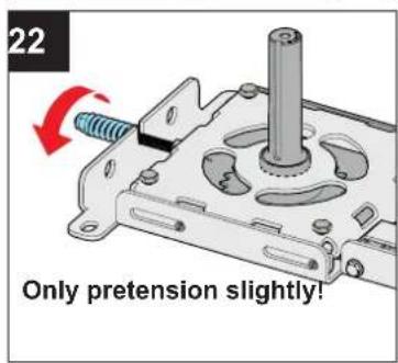
- Slightly pretension the chain (approx. 3 revolutions).
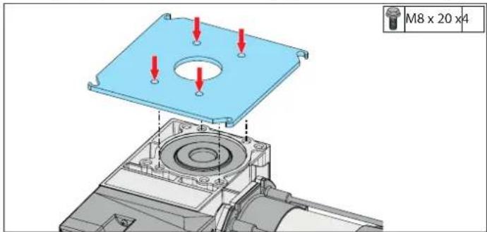
Fig. 28
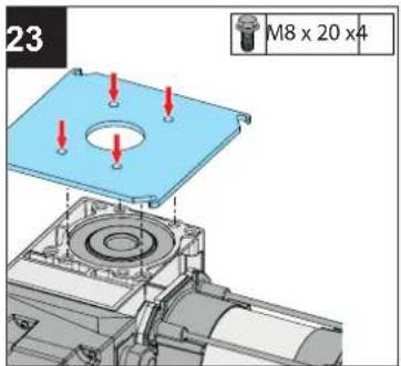
- Screw the intermediate plate to the operator.
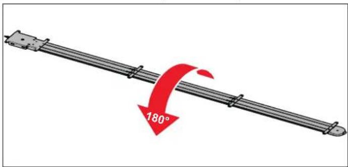
Fig. 29
- Turn the track unit through 180^ , as the next installation steps are carried out above head level.
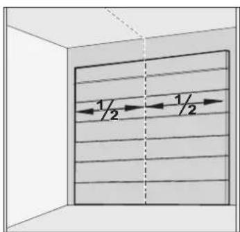
Fig. 30
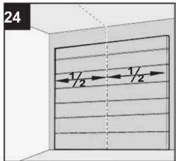
- Measure the centre of the door and attach the track unit to the garage ceiling correctly.
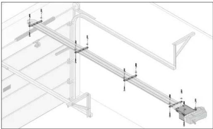
natural_image
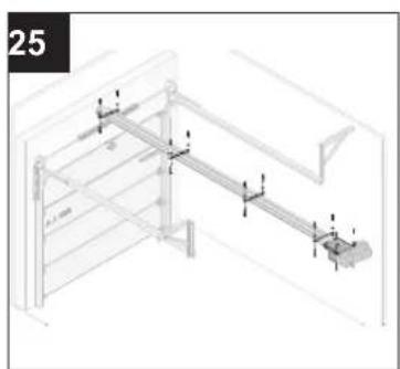
Technical line drawing of a mechanical assembly with beams and supports (no text or symbols)Fig. 31
- Ensure that all ceiling brackets are used to mount the operator on the ceiling.
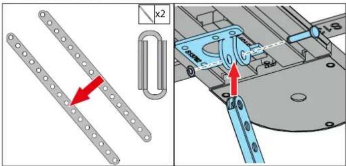
Fig. 32 Fig. 33
-
Place the two push rods together as shown. ⇒ This ensures greater stability.
-
Connect push rods to the carrier using Ben bolt and KL lock.
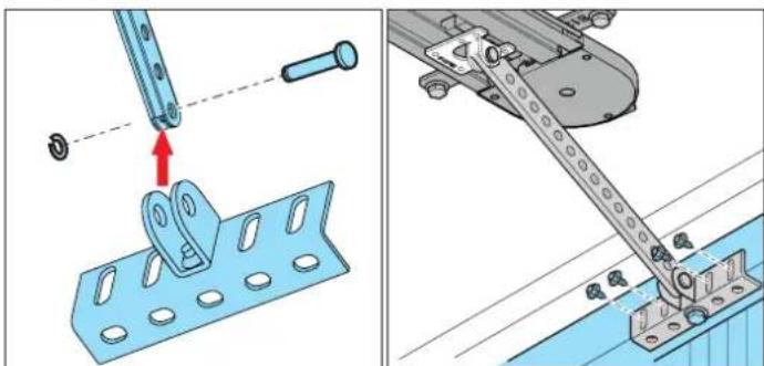
natural_image
Mechanical assembly diagram showing a metal bracket with mounting holes and a lever mechanism (no text or symbols)Fig. 34 Fig. 35
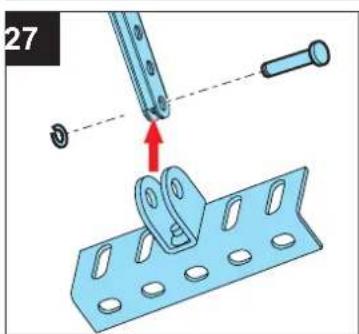
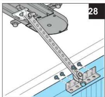
-
Connect door bracket to the push rods using Ben bolt and KL lock.
-
Bolt door bracket to the door.
4. Installation
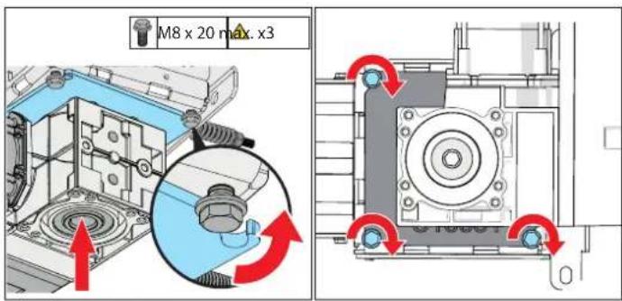
Fig. 36 Fig. 37
- Slide operator onto the motor shaft, turn the intermediate plate laterally and hook it into the screws of the motor support cover as shown.
- Tighten the screws to attach the intermediate plate firmly to the cover.
natural_image
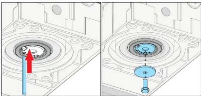
Technical diagram showing a mechanical component with a highlighted circular feature and a blue tool, no text or symbols present.Fig. 38 Fig. 39
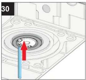
- Insert key into the groove between motor and motor shaft.
⇒ The key serves the purpose of force transmission between motor and motor shaft.
- Attach key using a screw and washer.
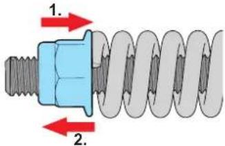
Fig.40
- Tension the chain as far as the stop. Loosen nut again by 3 – 4 turns.
4.5 Completing mechanical installation

NOTE
- The door must be moved manually to approximately the centre position before starting initial operation so that a detection of the motor direction is possible.
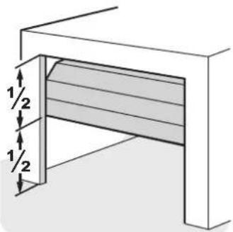
- Slide the door to centre position by hand.
natural_image
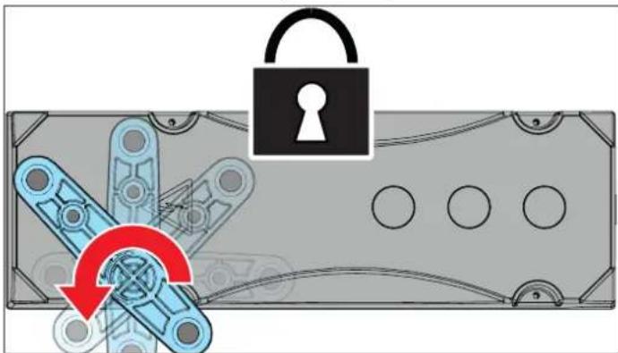
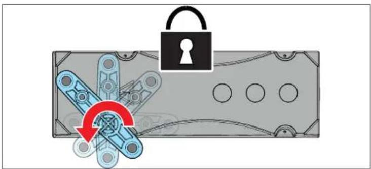
Diagram showing a lock and mechanical components with a red curved arrow indicating rotation or movement (no text or symbols)- Lock the operator
√ Operator is fully installed and ready for electrical connection!

INFORMATION
- Depending on the motor used, the locking/unlocking procedure may vary. Please follow the instructions for the motor.
5. Electrical connection, initial operation

NOTE
- Electrical connection and initial operation vary depending on the specific operator and control unit.
- The installation and operating manuals for the respective operator and control unit must be used.

www.sommer.eu
6.1 Important notes and information
Service the operator regularly as directed below. This ensures safe operation of your operator and a long service life. In particular, observe the warnings below.

DANGER

Danger if not observed!
If warnings are not observed, serious injury or death may result.
▶ All warnings must be complied with.

Danger due to electric current!
Contact with live parts may result in electric current flowing through the body. Electric shock, burns or death may result.
▶ All work on electrical components must be carried out by a trained electrician.
▶ Before performing work on the operator, including the connection of accessories, it must be disconnected from the power supply.
▶ Check that the operator is not live.
▶ Secure the operator against being switched back on.

WARNING

Danger of falling!
Unsafe or defective ladders may tip and cause fatal or serious accidents.
▶ Use only a non-slip, stable ladder.
▶ Ensure that ladders are safely positioned.

Danger for trapped persons!
Persons may be trapped inside the garage. If trapped persons cannot free themselves, severe injury or death may result.
▶ Check the function of the emergency release regularly, particularly from inside in the door CLOSE end position and if necessary, also from outside.
▶ You must have faults repaired professionally without delay.

Danger due to falling parts of doors!
Parts of the door may become detached and fall. If persons or animals are hit, this may cause serious injury or death.
▶ Always keep the moving door in sight.
▶ Keep all persons and animals away from the door until it is completely opened or closed.

Danger of crushing and shearing!
If the door moves and there are persons or animals in the movement area, crushing and shearing injuries may be caused by the mechanism and safety edges of the door.
▶ Only use the operator when you have a direct view of the door.
▶ All danger zones must be visible during the entire door operation.
▶ Always keep the moving door in sight.
▶ Keep persons and animals clear of the range of movement of the door.
▶ Never put your hand near the door when it is moving or near moving parts. In particular, do not reach into the moving push arm.
Do not reach into the ceiling suspension unit when the motor carriage is running along the rail.
▶ Do not drive through the door until it has opened completely.
▶ Never stand under the opened door.

Danger due to hot surfaces!
After frequent operation, parts of the operator or the control unit may become hot. If the cover is removed and hot parts are touched, they may cause burns.
▶ Allow the operator to cool down before removing the cover.

NOTE
- The use of unsuitable cleaning agents may damage the surface of the operator.
Clean the operator with a dry lint-free cloth only.
6. Maintenance and care
6.2 Maintenance schedule
| How often? | What? How? | |
| Once a month | • Test the emergency release | • See the separate Installation and Operating Manual for the operator used |
| • Test obstacle detection | • See the separate Installation and Operating Manual for the operator used | |
| • Test the photocell | • Interrupt the active photocell while the door is closing. The door must stop and open slightly. If automatic closing is activated, the door opens completely.• If necessary, clean the photocell. | |
| • Test obstacle recognition | • See the separate Installation and Operating Manual for the operator used | |
| Once a year | • Test the door and all moving parts | • As directed by the door manufacturer |
| • Check screws on door, ceiling or lintel | • Check that screws are tight and tighten if necessary | |
| As needed | • Chain and rail • maintenance-free | |
| • Rail | ||
| • Clean control unit/operator | ||
6.3 Care
- Disconnect the operator from the mains voltage. Then check that the power is disconnected.
- Remove loose dirt with a moist, lint-free cloth.
- Connect the operator to the mains voltage. Check that the voltage supply is connected.
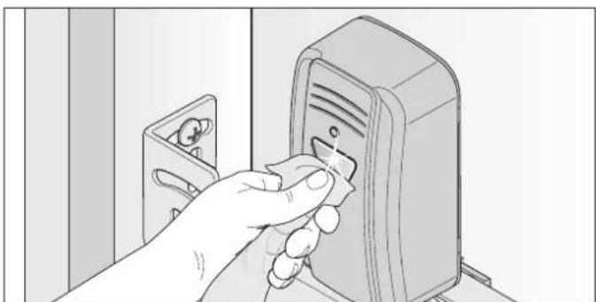
6.4 Cleaning the photocell
natural_image
Hand inserting a device into a device (no text or symbols visible)Fig. 1

- Do not change the position of the photocell when cleaning it.
- Clean the housing and reflectors of the photocell with a damp, lint-free cloth.
7. Taking out of operation, storage and disassembly
7.1 Important notes and information
Disassembly of the operator may only be performed by a qualified specialist. In particular, observe the warnings below.

DANGER

Danger if not observed!
If warnings are not observed, serious injury or death may result.
▶ All warnings must be complied with.

Danger due to electric current!
Contact with live parts may result in electric current flowing through the body. Electric shock, burns or death will result.
▶ All disassembly work on electrical components must be carried out by a trained electrician.
▶ Disconnect the mains plug before disassembling the operator.
▶ If an accumulator is connected, disconnect it from the control unit.
▶ Check that the operator is not live.
▶ Secure the operator against being switched back on.

WARNING

Danger of falling!
Unsafe or defective ladders may tip and cause serious or fatal accidents.
▶ Use only a non-slip, stable ladder.
▶ Ensure that ladders are safely positioned.

Danger of tripping and falling!
Unsafely positioned parts such as packaging, operator parts or tools may cause trips or falls.
▶ Keep the disassembly area free of unnecessary items.
Place all parts where no-one is likely to trip or fall over them.
The general workplace guidelines must be observed.

Danger due to hot surfaces!
After frequent operation, parts of the motor carriage or the control unit may become hot. If the cover is removed and hot parts are touched, they may cause burns.
▶ Allow the operator to cool down before removing the cover.

Danger due to optical radiation!
Looking into an LED at short range for an extended period may cause optical glare. This may temporarily reduce vision. This may cause serious or fatal accidents.
▶ Never look directly into an LED.

Risk of eye injury!
Chips flying when drilling may cause serious injuries to eyes and hands.
▶ Wear safety glasses when drilling.

Risk of injury in the head region!
Impact with suspended objects may cause serious abrasions and cuts.
▶ You must wear a safety helmet when disassembling suspended parts.

CAUTION

Risk of injury to hands!
Rough metal parts may cause abrasions and cuts when picked up or touched.
▶ You must wear your personal safety gloves when working with rough metal parts.
7.2 Taking out of operation and disassembly
The operator and its accessories must be disconnected from the power supply when taking them out of operation or during disassembly.
- Pull the mains plug out of the power outlet.
Then check that the power is disconnected.
- Disassembly is carried out in reverse order of installation.
7.3 Storage
Store the packaging units as follows:
- in enclosed, dry rooms so that they are protected from moisture
- at a storage temperature from -25^ to +65^
- secure to prevent falling
- leave room for unhindered passage

NOTE
- Improper storage may damage the operator. The operator must be stored in closed and dry rooms.
7. Taking out of operation, storage and disassembly
7.4 Disposal
WARNING

Danger caused by hazardous substances!
Improper storage, use or disposal of accumulators, batteries and operator components pose a risk to the health of humans and animals. Serious injury or death may result.
▶ Accumulators and batteries must be stored out of the reach of children and animals.
- Keep accumulators and batteries away from chemical, mechanical and thermal influences.
▶ Batteries may contain hazardous chemical substance which damage the environment and pose a risk to the health of humans and animals. Caution must be exercised, in particular when handling batteries containing lithium, as these can easily ignite and cause fires if not handled correctly.
▶ Batteries and accumulators in electrical appliances and which can be removed non-destructively must be disposed of separate from the appliance.

NOTE
▶ Dispose of all components in accordance with local and national regulations to avoid environmental damage.
▶ Wherever possible, avoid the production of waste. Please check before disposing of components whether it is possible to recycle them.

INFORMATION

This device is labelled in accordance with European Directive 2012/19/EU on used electrical and electronic devices (WEEE – waste electrical and electronic equipment).
This Directive provides the framework for the EU-wide return and recycling of used equipment.
Operator components that have been taken out of service as well as old accumulators and batteries must not be disposed of with household waste. Components which are no longer in use, old accumulators and batteries must be disposed of properly. You must observe the local and national regulations here. Contact your specialist retailer to find out more about current disposal channels.

8. Brief instructions for installation
natural_image
Mechanical assembly diagram showing a metal bracket with multiple blue components and red directional arrows indicating motion (no text or symbols)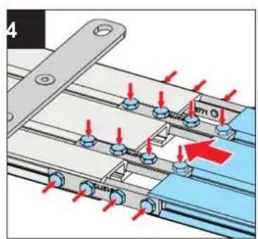
natural_image
Pure mechanical component diagram showing a linear beam with evenly spaced supports (no text or symbols)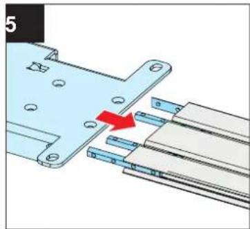
natural_image
Mechanical assembly diagram showing a metal bracket with mounting holes and a red arrow indicating direction (no text or symbols)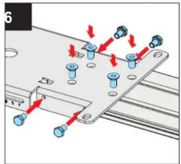
natural_image
Mechanical assembly diagram showing a blue component inserted into a metal frame with a red arrow indicating direction (no text or symbols)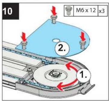
natural_image
Mechanical assembly diagram showing a gear and shaft with red arrows indicating motion (no text or symbols)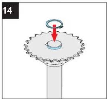
natural_image
Diagram of a mechanical component with a rotating ring and base, no text or symbols present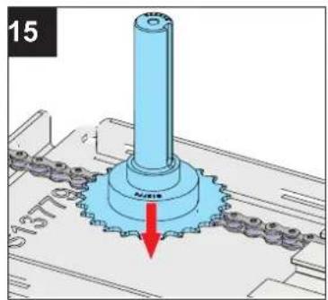
natural_image
Mechanical assembly diagram showing a shaft and gear mechanism with a red arrow indicating motion (no text or symbols)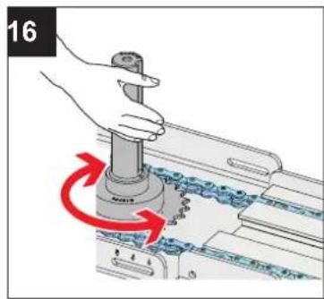
natural_image
3D mechanical assembly diagram showing a screw inserted into a housing with a blue component and red arrow indicating direction (no text or symbols)8. Brief instructions for installation
natural_image
Mechanical assembly diagram showing a disassembled hard drive into a plastic housing (no text or symbols)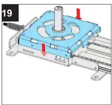
natural_image
Mechanical assembly diagram showing a blue box with internal components and red arrows indicating motion direction (no text or symbols)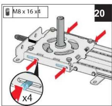
natural_image
Technical line drawing of a mechanical assembly or lifting device (no text or symbols visible)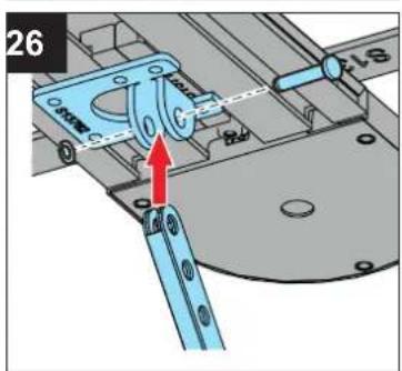
natural_image
Mechanical assembly diagram showing a lever mechanism interacting with a blue surface (no text or symbols visible)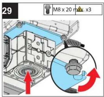
natural_image
Technical diagram of a mechanical component with a highlighted circular feature and red arrow indicating direction (no text or symbols)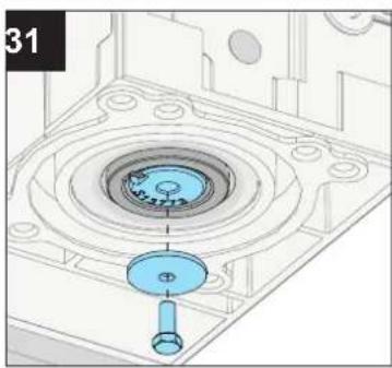
natural_image
3D mechanical assembly diagram showing a circular component with a blue handle and a central hub, no text or symbols present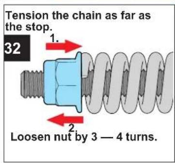

natural_image
Green checkmark symbol on white background (no text or symbols)8. Brief instructions for installation
Emergency release
natural_image
Diagram showing a lock and mechanical components with a red circular arrow indicating rotation (no text or symbols)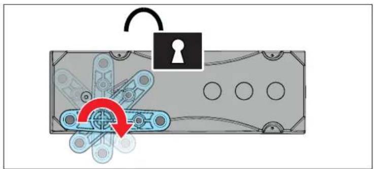
natural_image
Diagram showing a lock and mechanical assembly with a red circular arrow indicating rotation (no text or symbols)- EN TRANSLATION OF THE ORIGINAL INSTALLATION AND OPERATING MANUAL
- Warranty
- Service
- Copyright and proprietary rights
- About this Installation and Operating Manual 4
- General safety instructions 8
- Description of function and product 10
- Installation 16
- Electrical connection, initial operation 24
- Taking out of operation, storage and disassembly 27
- Brief instructions for installation 29
- About this Installation and Operating Manual
- Storage and circulation of the Installation and Operating Manual
- www.sommer.eu
- Important for translations
- Description of the product type
- Target groups of the Installation and Operating Manual
- Explanation of symbols and notes
- Signal word
- DANGER
- WARNING
- CAUTION
- NOTE
- INFORMATION
- Information regarding the depiction of text
- Intended use of the operator
- http://som4.me/cgdo
- http://som4.me/konform
- Improper use of the operator
- Qualifications of personnel
- Qualified specialist for installation, commissioning and disassembly
- Instructing the user and handover of documents
- Information for the user
- The user is responsible for:
- Basic safety instructions for operation
- Danger if not observed!
- Danger due to electric current!
- Danger due to use of the system with incorrect settings or when it is in need of repair!
- Danger caused by hazardous substances!
- Danger for trapped persons!
- Danger due to parts projecting into publicly accessible areas!
- Danger due to falling parts of doors!
- Danger of entrapment!
- Danger of crushing and shearing!
- Danger caused by the door falling!
- Danger of falling!
- Danger of tripping and falling!
- Danger due to optical radiation!
- Risk of eye injury!
- Risk of hand injury!
- Risk of injury in the head region!
- Additional safety information for the radio remote control Danger of crushing and shearing!
- Notes and information on operation and remote control
- Description of function and product
- The operator and its mode of operation
- Safety equipment
- Product designation
- Tool symbols
- Other symbols
- Technical data
- Door types and accessories
- Door type Accessories
- Installation
- Required tools and personal protective equipment
- Important notes and information
- Danger due to projecting parts!
- Danger due to falling ceiling and wall parts!
- Risk of injury in the head region
- Risk of injury to hands!
- Preparing for installation
- Removal of actuation parts
- Disabling mechanical locks
- Checking the mechanism and weight balance
- Danger due to falling parts of doors or complete door panels!
- Emergency release
- Installing the drive system
- Completing mechanical installation
- Electrical connection, initial operation
- Important notes and information
- Danger due to hot surfaces!
- Maintenance and care
- Care
- Taking out of operation, storage and disassembly
- Important notes and information
- Taking out of operation and disassembly
- Storage
- Disposal
- Brief instructions for installation
Brand : Sommer
Model : GIGAline
Category : Garage door opener