
Ultinon Pro9000 11012U90CWX2 - Lighting PHILIPS - Free user manual and instructions
Find the device manual for free Ultinon Pro9000 11012U90CWX2 PHILIPS in PDF.


| Brand | Philips |
| Model | Ultinon Pro9000 11012U90CWX2 |
| Product Category | Automotive LED Headlight Bulb |
| Bulb Types Compatible | H1, H3, H4, H7, H11, HB3, HB4, FOG, HIR2 |
| Light Source | LED (Philips Ultinon) |
| Color Temperature | 6000K (Cool White) |
| Luminous Flux (per lamp) | Approx. 2500 lumens (pair: 5000 lm) |
| Input Voltage | 12V DC |
| Power Consumption | ~40W per lamp |
| Heat Sink Material | Aluminum (passive cooling) |
| Waterproof Rating | IP67 (estimated, driver sealed) |
| Lifespan | Up to 30,000 hours |
| Operating Temperature | -40°C to +85°C |
| Dimensions (L x W x H) | Approx. 70mm x 30mm x 90mm (bulb with heat sink) |
| Weight (single lamp) | Approx. 120g (including driver) |
| Dimmable | No (non-dimmable) |
| Certifications | CE, ECE (estimated) |
| Package Contents | 2x LED burners, 2x drivers, 1x hex key, 8x cable ties, product manual |
| Warranty | 1 year (manufacturer warranty) |
Frequently Asked Questions - Ultinon Pro9000 11012U90CWX2 PHILIPS
User questions about Ultinon Pro9000 11012U90CWX2 PHILIPS
0 question about this device. Answer the ones you know or ask your own.
Ask a new question about this device
Download the instructions for your Lighting in PDF format for free! Find your manual Ultinon Pro9000 11012U90CWX2 - PHILIPS and take your electronic device back in hand. On this page are published all the documents necessary for the use of your device. Ultinon Pro9000 11012U90CWX2 by PHILIPS.
USER MANUAL Ultinon Pro9000 11012U90CWX2 PHILIPS
natural_image
Technical illustration of a mechanical component with gear and mounting bracket (no text or symbols)GB Thank you very much for purchasing this product. To facilitate long-term use, please carefully read this User Manual before use. After reading, keep the User Manual safe so that it is available for use at any time.
Table of Content
Packaging List....3
Important Information....3
Installation for H4 and H7....5
Installation for FOG, H11, HIR2, HB3 and HB4....6
Centre ring adjustment....8
Centre ring alignment of HIR2, HB3, HB4, H11 and FOG....8
Precautions H11 and FOG....10
Installation for H1 and H3....11
Correct beam performance....13
Troubleshooting....13
Recycling, Warranty and Service....14
1 Packing list
| Item Description | H7, H4 H11, FOG & HIR2 | HB3 H1, H3 | HB4 | |||
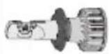 | Ultinon Pro lamps burners with heat sink x 2 | √ | √ | √ | √ | √ |
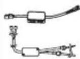 | Drivers x 2 | √ | ||||
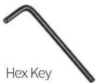
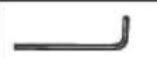 | Hex Key x 1 | √ | √ | √ | ||
 | Plastic Tie x 8 | √ | ||||
 | Additional HB4 O-Ring x 2 | √ | √ | |||
 | Product Manual x1 | √ | √ | √ | √ | √ |
2 Important
Please read these instructions carefully before installing the Ultinon Pro lamp.
Precautions
- Before installing the Ultinon Pro lamps, please ensure that the lamps are not damaged or broken, and have not fallen on the ground. If any of these conditions exist, please do not install the LED bulbs onto your vehicle.
- The temperature of the Ultinon Pro lamps burner can be very high. Do not place flammable materials, such as paper, cloth, or other materials, close to the LED bulb.
- Keep the LED bulb out of areas that are exposed to flames or prone to combustion, such as gas or petrol stations.
- Keep the LED bulb out of areas with high amounts of dust.
Warning
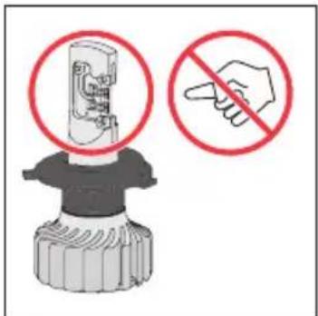
- The burner body and LED surface can reach very high temperatures. Do not touch the area with the hands or allow any skin contact as it may result in severe burns. Do not touch the LED ribbon bonding area! (Refer to picture below)
- The LED light intensity is very high while turned on. Do not look directly into the beam to avoid damage to the eyes.
- Do not wash the vehicle when the headlights are turned on. Changes in temperature may cause damage to or an unexpected reaction from the LED headlight.
- Do not expose the surface of the LED bulb to dust or oils, or cause the surface to bear shock or otherwise become damaged.
- Keep out of reach of children.
- Warning – Do not touch this area
Other Information
- Please ensure that the product comes from a legal sales channel.
• After installation, check that the high and low beams, the flash function, and other electrical equipment on the dashboard work and that no warnings occur. If anything abnormal happen, Philips LED CANbus adapter could be a solution.
• After installation, ensure that the waterproof gasket is fitted correctly to reduce the risk of leakage. - Do not bend the cables excessively, especially near the heat sink area.
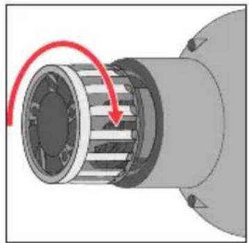
3 Installation steps for H4 and H7
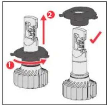
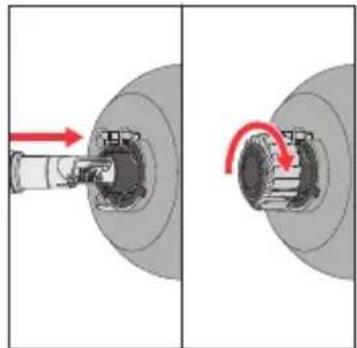
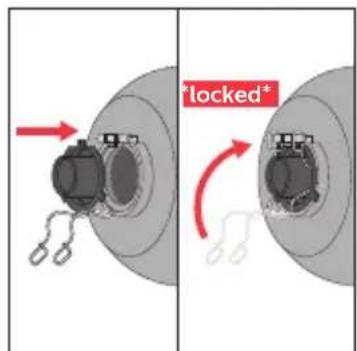
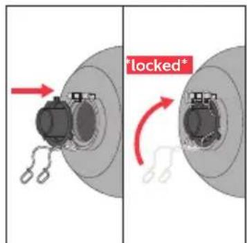
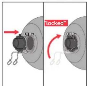
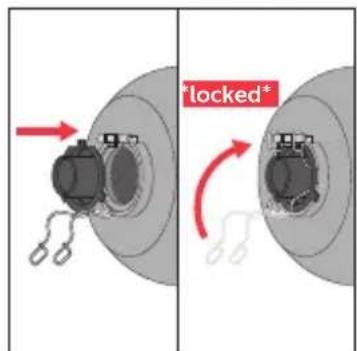
- Twist and pull off the center ring
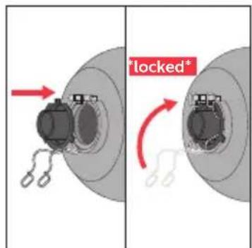
• Install and fixate center ring in headlamp
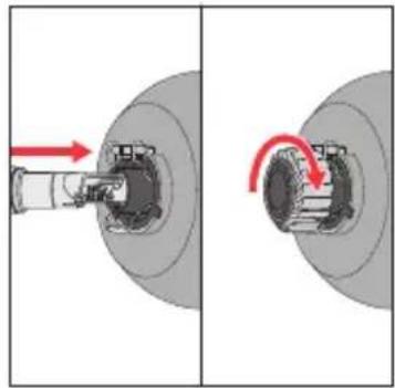
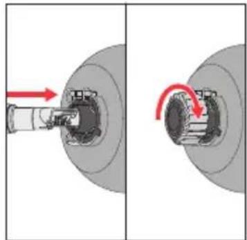
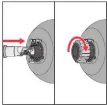
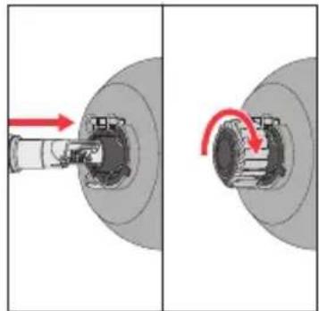
- Insert and fixate LED bulb by rotating until end stop
natural_image
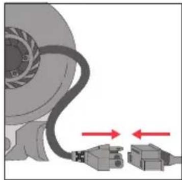
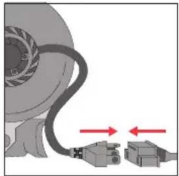
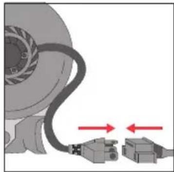
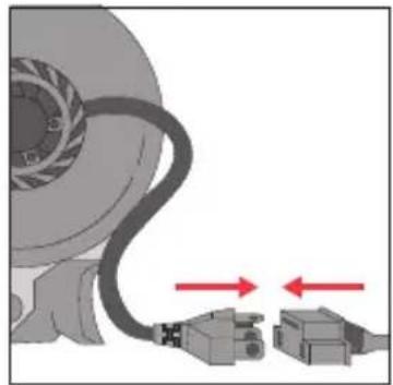
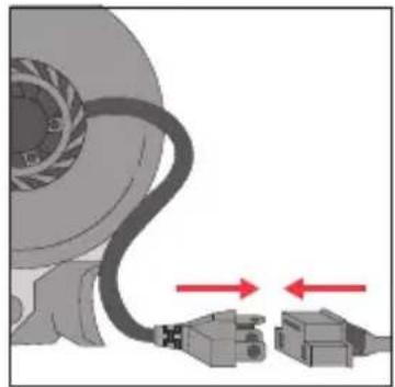
Mechanical assembly diagram showing a shaft and housing with red directional arrows indicating motion (no text or symbols)- Connect power line
- Optional and only for H7 – Beam pattern can be optimized by rotating LED bulb, LED PCB should be vertical
natural_image
Diagram of a mechanical component with two connected USB connectors and a curved cable, showing bidirectional arrows (no text or symbols)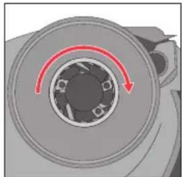
natural_image
Mechanical component diagram showing a circular housing with a red curved arrow indicating rotational motion (no text or symbols)Installation for FOG, H11, HIR2, HB3, HB4
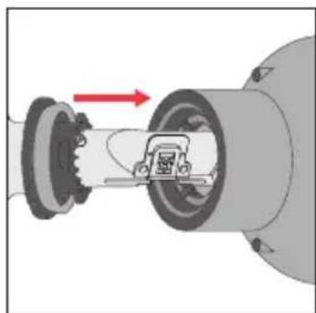
• Install the bulb inside the luminaire.
natural_image
Mechanical assembly diagram showing a motor inside a cylindrical housing with directional arrows indicating motion (no text or symbols)- Rotate the heatsink
- Connect the plug to the power socket
- If the original installed bulb is HB4 bulb type; please replace the red o-ring with the black o-ring.
(HB4 = black o-ring; HB3 = red o-ring)
natural_image
Mechanical component diagram showing a rotating shaft with a red arrow indicating motion (no text or symbols)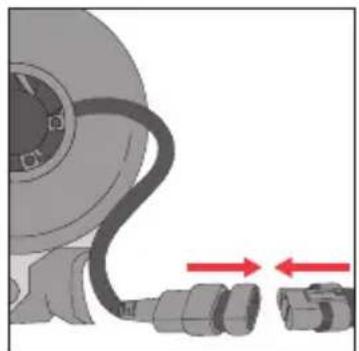
natural_image
Illustration of a mechanical component with a curved cable and two connectors, no text or symbols present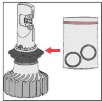
Centre ring adjustment target
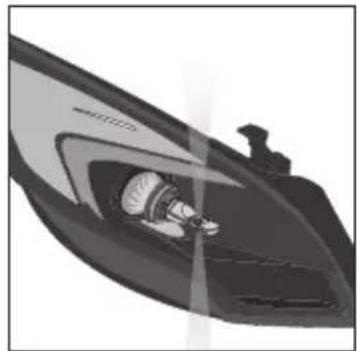
- If the bulb is not in vertical position inside the luminaire, please follow below instruction for adjusting centre ring angle.
- Make sure the LED emit light to the left and right, burner is in vertical position
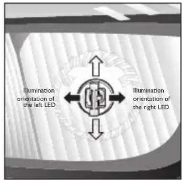
Centre Ring alignment of HIR2, HB3, HB4, H11 and FOG
- Bulb not perpendicular (Not preferred)
- Screw inwards the two reference screws with the Hex key.
natural_image
Illustration of a person inside a car's airfoil (no text or symbols visible)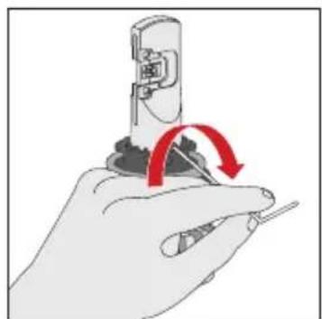
natural_image
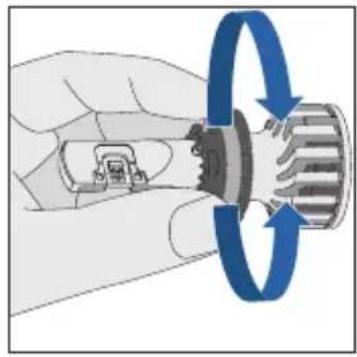
Hand holding a screwdriver with a red circular arrow indicating rotation (no text or symbols)- Rotate burner over the centre ring
- Screw outwards the two reference screws.
- For easy adjustment and easy screwing out it is necessary to apply force to pull the centre ring downwards.
• Bulb perpendicular (Preferred)
natural_image
Illustration of a hand holding a mechanical component with blue circular arrows indicating rotational flow (no text or symbols)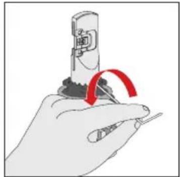
natural_image
Illustration of a hand holding a tool with a red curved arrow indicating rotation (no text or symbols)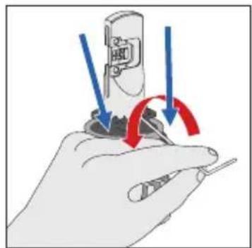
natural_image
Illustration of a hand holding a screwdriver with arrows indicating rotation or adjustment (no text or symbols)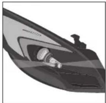
natural_image
Illustration of a stylized boat or speedboat with a visible wake or gear, no text or symbols present.Precautions for H11 / FOG
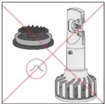
- Do not dissemble. Risk of small component (spring) coming loose
- Do not dissemble. Special tools are required for re-assembly
- Keep centre ring pressed towards the heatsink and the burner.
natural_image
Technical illustration of a mechanical device with cross-sectional view and internal components (no text or symbols)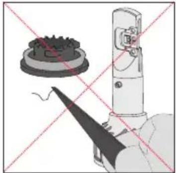
natural_image
Diagram of a robotic arm with a gear and tool, intersected by red diagonal lines (no text or symbols)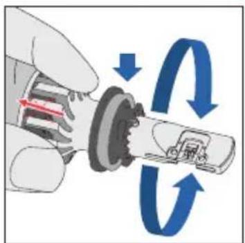
- Screw top should be same height as centre ring surface after the adjustment
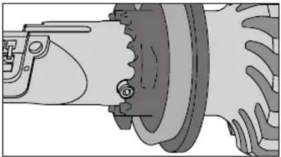
natural_image
Mechanical assembly diagram showing a gear and housing component (no text or symbols)Installation for H1 and H3
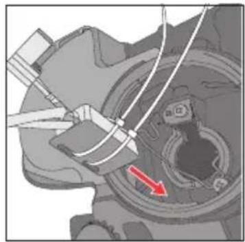
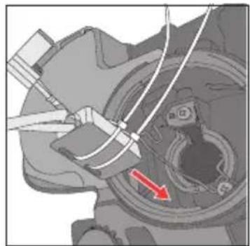
- Fix the driver box inside the luminaire firstly.
- Screw out the heatsink from the burner
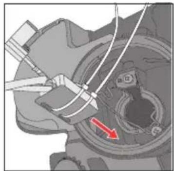
natural_image
Mechanical assembly diagram showing a gear and wheel assembly with a red arrow indicating direction (no text or symbols present)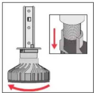
natural_image
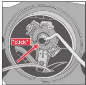
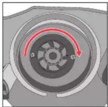
Mechanical assembly diagram showing a rotating component with a magnified inset illustrating the process (no text or symbols)• Fix the burner onto the luminaire.
- Screw on the heatsink onto the burner.
- Connect the cable between driver to burner and driver to power socket.
natural_image
Mechanical component diagram showing a circular dial with red directional arrows indicating motion or rotation (no text or symbols)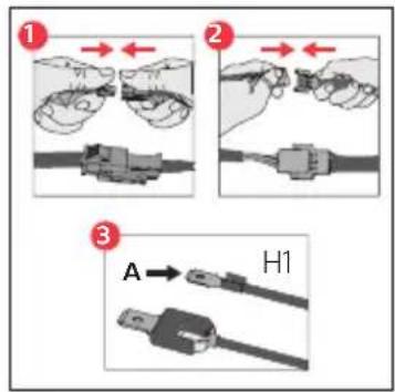
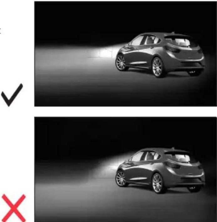
Correct beam performance
- Correct beam with clear cut-off: Superior visibility in farfield. Reduced glaring, enhancing driver and traffic safety
4 Troubleshooting
If the Ultinon Pro fails to operate, please perform the following actions:
- Check that the power connectors are well connected.
- Ensure that the vehicle headlight switch is in the "ON" position.
- Ensure that the vehicle battery has enough power to power the Ultinon Pro
5 Recycling

Your product is designed and manufactured with high quality material and components that can be recycled and reused. The following symbol attached to the product signifies that the product is covered by the European Directive 2002/96/EC.
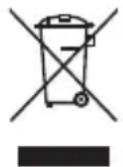
Never dispose of the product with other waste. Please inquire about the local regulations about the separated collection of electrical and electronic products. The correct disposal of used old products helps prevents potentially negative consequences on the environment and human health.
6 Warranty and Service
If you have any problems with the product or need service or need information, please visit www.philips.com/automotive or contact the Philips call center in your country. If there is no call center in your country, please consult your local Philips dealer.
Warranty terms
Philips does not warrant its goods against any defect or damage caused by transportation, storage, improper installation, maintenance, internal or external hostile environment, misuse, abuse, negligence, accident, modification, tampering, the attachment of any unauthorized accessory, alteration to the goods, or any other conditions whatsoever that do not constitute a defect in material and/or workmanship. Philips sole responsibility under this warranty shall be, at its option, to either repair or replace any goods which fail during the warranty period, provided that Buyer has promptly reported same to Philips in writing, and complies with the provisions of this Warranty.
In case of warranty claim, please provide the following information together with proof of purchase:
Name ____ address ____
Phone ____ postal code ____
Purchased from: (please provide name and location of retail outlet)
繁體中文
其他資訊
natural_image
Mechanical assembly diagram showing a shaft and housing with red directional arrows indicating motion (no text or symbols)· 連接電源線路。
natural_image
Diagram showing a car wheel connected to two USB connectors with red arrows indicating connection direction (no text or symbols)natural_image
Mechanical component diagram showing a circular housing with a red curved arrow indicating rotational motion (no text or symbols)natural_image
Mechanical assembly diagram showing a rotating shaft connected to a housing with a valve mechanism (no text or symbols)natural_image
Mechanical component diagram showing a cylindrical shaft with internal grooves and a red arrow indicating motion (no text or symbols)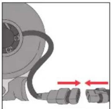
natural_image
Illustration of a mechanical component with a curved cable and two connected connectors, no text or symbols present.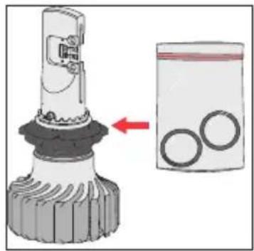
natural_image
Diagram showing a mechanical component being inserted into a bag with three circular holes (no text or symbols present)中央環調整目標
natural_image
Illustration of a person inside a vehicle's roof, showing structural details (no text or symbols)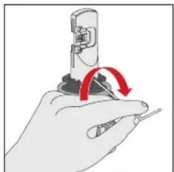
natural_image
Illustration of a hand using a tool to adjust or install a mechanical component, with red arrows indicating rotation (no text or symbols present)natural_image
Illustration of a hand holding a mechanical component with blue circular arrows indicating rotational flow (no text or symbols)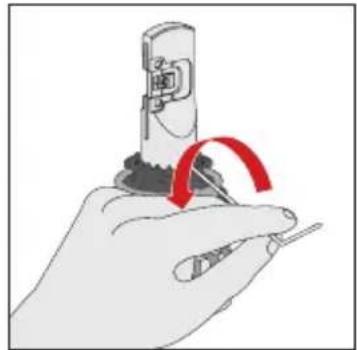
natural_image
Illustration of a hand using a tool to press or install a mechanical component, with a red curved arrow indicating motion (no text or symbols present)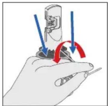
natural_image
Illustration of a hand holding a screwdriver with arrows indicating rotation or adjustment (no text or symbols)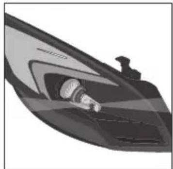
natural_image
Illustration of a stylized boat hull with a side-mounted mast and illuminated hull (no text or symbols)H11 / FOG 注意事項
natural_image
Technical illustration of a mechanical device with cross-sectional view and no visible text or symbols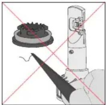
natural_image
Diagram showing a mechanical device with a gear-like component and a tool, intersected by red diagonal lines (no text or symbols)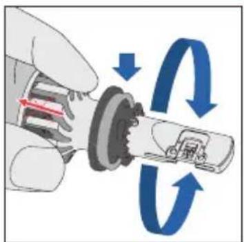
natural_image
Mechanical assembly diagram showing a gear and housing component (no text or symbols)安裝 H1 及 H3
· 先將驅動器固定在燈具內部。
·從燈泡燈體中旋出散熱器。
natural_image
Mechanical assembly diagram showing a wheel and gear assembly with a red arrow indicating a specific component (no text or symbols present)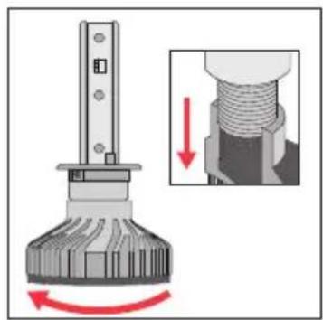
natural_image
Mechanical assembly diagram showing a rotating component with a magnified inset illustrating the process (no text or symbols)natural_image
Mechanical component diagram showing a circular gear or impeller with red motion arrows indicating rotational direction (no text or symbols)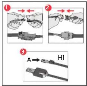
正確的光束效能
その他
natural_image
Mechanical assembly diagram showing a shaft and housing with red directional arrows indicating motion (no text or symbols)・電源ケーブルを接続します。
natural_image
Diagram of a car wheel connected to two USB connectors with red directional arrows indicating connection (no text or symbols)natural_image
Mechanical component diagram showing a circular housing with a red curved arrow indicating rotational motion (no text or symbols)natural_image
Mechanical assembly diagram showing a motor inside a cylindrical housing with directional arrows indicating motion (no text or symbols)・ヒートシンクを回します。
・プラグを電源ソケットに接続します。
natural_image
Mechanical component diagram showing a rotating shaft with a red arrow indicating motion (no text or symbols)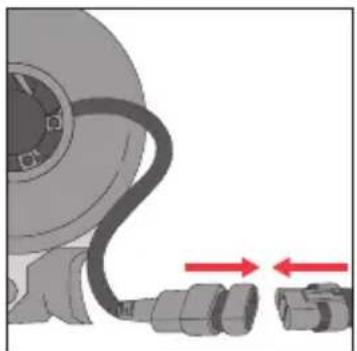
natural_image
Illustration of a mechanical component with a curved cable and two connected connectors, no text or symbols present.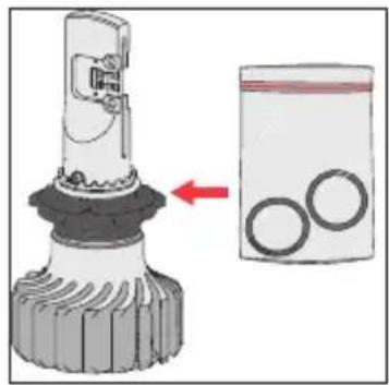
natural_image
Diagram showing a mechanical component being inserted into a bag with three circular holes (no text or symbols present)センターリングの調整が必要となる場合
natural_image
Illustration of a person inside a car's airfoil (no text or symbols visible)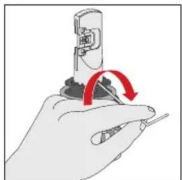
natural_image
Hand holding a screwdriver with a red circular arrow indicating rotation (no text or symbols)natural_image
Illustration of a hand holding a mechanical component with blue circular arrows indicating rotational flow (no text or symbols)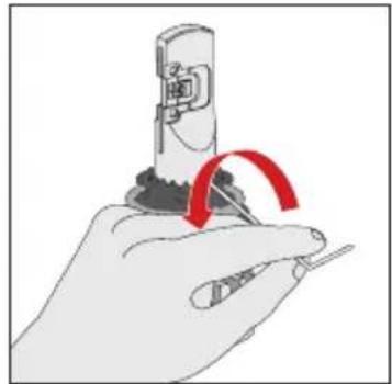
natural_image
Illustration of a hand holding a tool with a red curved arrow indicating rotation (no text or symbols)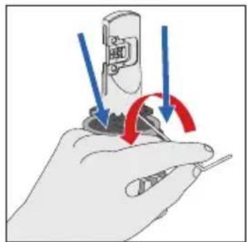
natural_image
Illustration of a hand holding a screwdriver with arrows indicating rotation or adjustment (no text or symbols)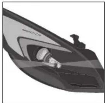
natural_image
Illustration of a stylized boat or speedboat with a visible wake or gear, no text or symbols present.H11 とフォグランプに関する注意事項
natural_image
Technical illustration of a mechanical device with cross-sectional view and internal components (no text or symbols)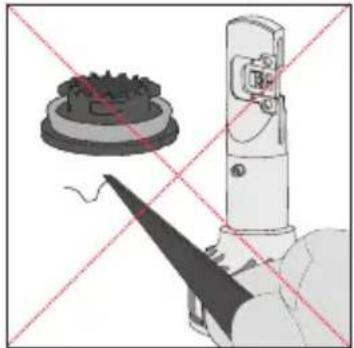
natural_image
Diagram of a robotic arm with a gear and tool, crossed by red diagonal lines (no text or symbols)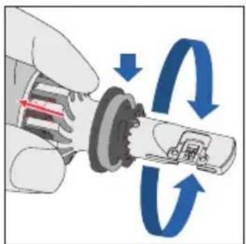
natural_image
Mechanical assembly diagram showing a gear and housing component (no text or symbols)H1 および H3 の取り付け
natural_image
Mechanical assembly diagram showing a wheel and gear assembly with a red arrow indicating a specific component (no text or symbols present)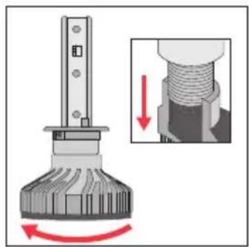
natural_image
Mechanical assembly diagram showing a rotating component with a magnified inset illustrating the process (no text or symbols)natural_image
Mechanical component diagram showing a circular dial with red directional arrows indicating motion or rotation (no text or symbols)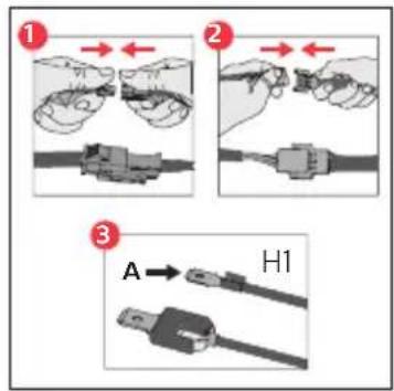
正常な照射性能
기타 정보
natural_image
Mechanical assembly diagram showing a shaft and housing with red directional arrows indicating motion (no text or symbols)·전선을 연결합니다
natural_image
Diagram showing a car wheel connected to two USB connectors with red arrows indicating connection direction (no text or symbols)natural_image
Mechanical component diagram showing a circular housing with a red curved arrow indicating rotational motion (no text or symbols)FOG, H11, HIR2, HB3, HB4 설치
natural_image
Mechanical assembly diagram showing a rotating shaft connected to a housing with a valve mechanism (no text or symbols)·방열기를 돌립니다
·전원 소켓에 플러그를 꽃습니다
natural_image
Mechanical component diagram showing a rotating shaft with a red arrow indicating motion (no text or symbols)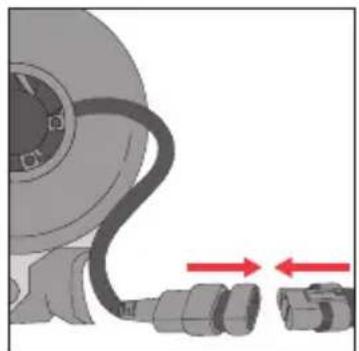
natural_image
Illustration of a mechanical component with a curved cable and two connected connectors, no text or symbols present.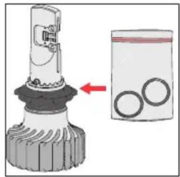
센터 링 조정 대상
natural_image
Illustration of a person inside a vehicle's roof, showing structural details (no text or symbols)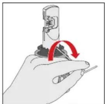
natural_image
Illustration of a hand using a tool to adjust or install a mechanical component, with red arrows indicating rotation (no text or symbols present)· 센터 링 위로 버너를 돌립니다
natural_image
Illustration of a hand holding a mechanical component with blue circular arrows indicating rotational flow (no text or symbols)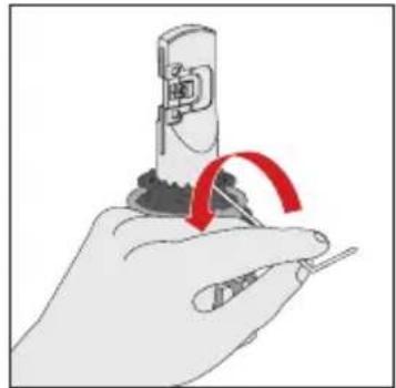
natural_image
Illustration of a hand holding a screwdriver with a red curved arrow indicating rotation (no text or symbols)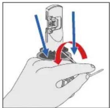
natural_image
Illustration of a hand holding a screwdriver with arrows indicating rotation or adjustment (no text or symbols)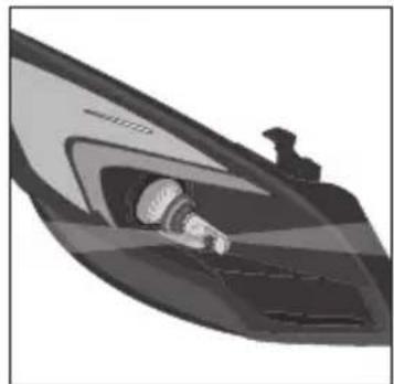
natural_image
Illustration of a stylized boat hull with a side-mounted mast and illuminated hull (no text or symbols)H11/FOG 관련 주의사항
natural_image
Diagram of a mechanical device with a base and a pin, showing no text or symbols.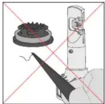
natural_image
Diagram showing a mechanical device with a gear-like component and a tool, both crossed by red diagonal lines (no text or symbols)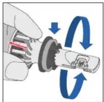
natural_image
Mechanical assembly diagram showing a gear and housing component (no text or symbols)H1 및 H3 설치
natural_image
Mechanical assembly diagram showing a wheel and gear assembly with a red arrow indicating a specific component (no text or symbols present)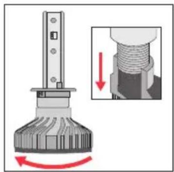
natural_image
Mechanical assembly diagram showing a rotating component with a magnified inset illustrating the process (no text or symbols)·조명 기구에 버너를 고정합니다.
·버너에 방열기를 돌려 끼웁니다.
natural_image
Mechanical component diagram showing a circular gear or impeller with red motion arrows indicating rotational direction (no text or symbols)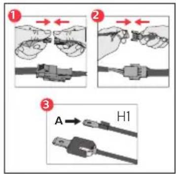
정확한 빈 성능
其他信息
natural_image
Mechanical assembly diagram showing a shaft and housing with red directional arrows indicating motion (no text or symbols)· 连接电源线。
natural_image
Diagram of a car wheel connected to two USB connectors with red directional arrows indicating connection (no text or symbols)natural_image
Mechanical component diagram showing a circular housing with a red curved arrow indicating rotational motion (no text or symbols)natural_image
Mechanical assembly diagram showing a rotating shaft connected to a housing with a valve mechanism (no text or symbols)· 旋转散热器。
· 将插头连接至电源插座。
natural_image
Mechanical component diagram showing a rotating shaft with a red arrow indicating motion (no text or symbols)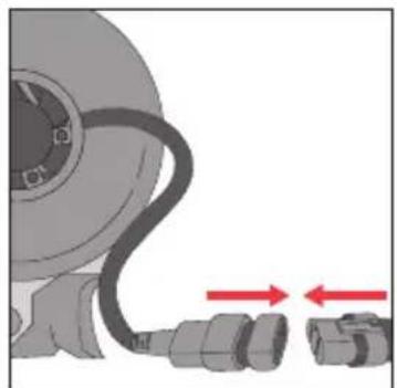
natural_image
Illustration of a mechanical component with a curved cable and two connected connectors, no text or symbols present.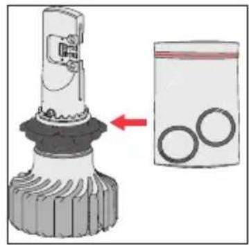
natural_image
Illustration of a hairdryer with a magnified view showing two circular components (no text or symbols)中心环调整目标
natural_image
Illustration of a person inside a car wheel, showing the wheel and dashboard (no text or symbols)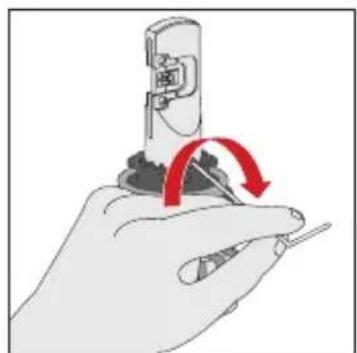
natural_image
Hand holding a screwdriver with a red circular arrow indicating rotation (no text or symbols)· 将灯体旋转到中心环上。
· 向外拧两个参考螺丝。
natural_image
Illustration of a hand holding a mechanical component with blue circular arrows indicating rotational flow (no text or symbols)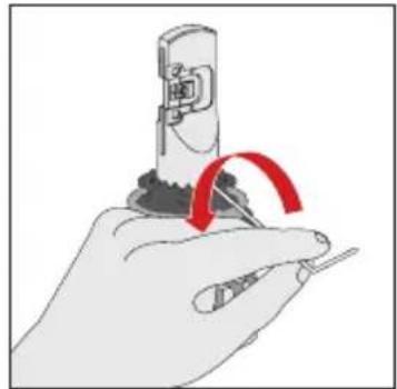
natural_image
Illustration of a hand holding a tool with a red curved arrow indicating rotation (no text or symbols)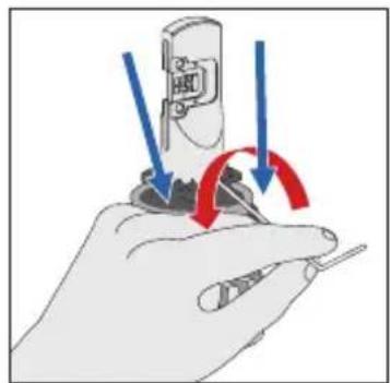
natural_image
Illustration of a hand holding a screwdriver with arrows indicating rotation or adjustment (no text or symbols)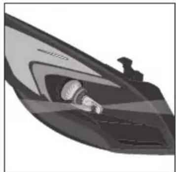
natural_image
Illustration of a stylized boat or speedboat with a visible wake or gear, no text or symbols present.H11/FOG 的预防措施
natural_image
Technical illustration of a mechanical device with cross-sectional view and internal components (no text or symbols)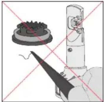
natural_image
Diagram of a robotic arm with a gear and tool, crossed by red diagonal lines (no text or symbols)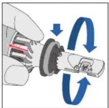
natural_image
Mechanical assembly diagram showing a gear and housing component (no text or symbols)H1 和 H3 的安装
· 首先将驱动器盒固定到灯具内。
· 将散热器从灯体中拧出。
natural_image
Mechanical assembly diagram showing a gear and wheel assembly with a red arrow indicating direction (no text or symbols present)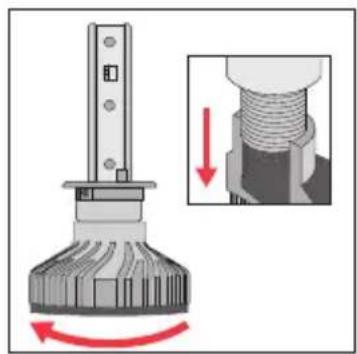
natural_image
Mechanical assembly diagram showing a rotating component with a magnified inset illustrating the process (no text or symbols)natural_image
Mechanical component diagram showing a circular dial with red directional arrows indicating motion or rotation (no text or symbols)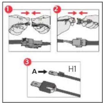
正确的光束性能
Lumileds is the warrantor of this product.
Philips and the Philips Shield Emblem are registered trademarks of
Koninklijke Philips N.V. and are used under license.
2020 © Lumileds Holding B.V. All rights reserved.
2020 © Lumileds Holding B.V. All rights reserved.
2020 © Lumileds Holding B.V. All rights reserved.
Lumileds 是此产品的担保人。
- Table of Content
- Packing list
- Important
- Precautions
- Warning
- Other Information
- Installation steps for H4 and H7
- Installation for FOG, H11, HIR2, HB3, HB4
- Centre ring adjustment target
- Centre Ring alignment of HIR2, HB3, HB4, H11 and FOG
- Precautions for H11 / FOG
- Installation for H1 and H3
- Correct beam performance
- Troubleshooting
- Recycling
- Warranty and Service
- Warranty terms
- 繁體中文
- 其他資訊
- 中央環調整目標
- H11 / FOG 注意事項
- 安裝 H1 及 H3
- 正確的光束效能
- その他
- センターリングの調整が必要となる場合
- H11 とフォグランプに関する注意事項
- H1 および H3 の取り付け
- 正常な照射性能
- 기타 정보
- FOG, H11, HIR2, HB3, HB4 설치
- 센터 링 조정 대상
- H11/FOG 관련 주의사항
- H1 및 H3 설치
- 정확한 빈 성능
- 其他信息
- 中心环调整目标
- H11/FOG 的预防措施
- H1 和 H3 的安装
- 正确的光束性能
Brand : PHILIPS
Model : Ultinon Pro9000 11012U90CWX2
Category : Lighting