XT Classic - Coffee machine Dalla Corte - Free user manual and instructions
Find the device manual for free XT Classic Dalla Corte in PDF.


| Product Type | Commercial Espresso Machine |
| Brand | Dalla Corte |
| Model | XT Classic |
| Dimensions (W x D x H) | 600 x 550 x 500 mm |
| Weight | 55 kg |
| Power Supply | 230 V ~ 50 Hz, 3000 W |
| Boiler Type | Multi-boiler (coffee and steam) |
| Water Supply | Plumbed into mains |
| Controls | Electronic with LCD display |
| Functions | Espresso brewing, steam wand, hot water |
| Number of Group Heads | 2 |
| Steam Wand | Articulating with insulated handle |
| Hot Water Spout | Yes, separate |
| Pump | Rotary, adjustable pressure |
| Temperature Control | PID digital, individually for each group |
| Pre-infusion | Programmable with pressure profiling |
| Cup Warmer | Yes, on top of machine |
| Drain | Integrated drip tray and drain line |
| Safety Features | Auto shut-off, overheat protection, safety valve |
| Cleaning & Maintenance | Automatic backflush, daily group head cleaning |
| Descaling | Recommended every 3-6 months with Dalla Corte descaling solution |
| Repairability | Replaceable components, service available |
| Included Accessories | Portafilters, baskets, tamper, cleaning tools |
Frequently Asked Questions - XT Classic Dalla Corte
User questions about XT Classic Dalla Corte
0 question about this device. Answer the ones you know or ask your own.
Ask a new question about this device
Download the instructions for your Coffee machine in PDF format for free! Find your manual XT Classic - Dalla Corte and take your electronic device back in hand. On this page are published all the documents necessary for the use of your device. XT Classic by Dalla Corte.
USER MANUAL XT Classic Dalla Corte

bar
| Category | Value | |---|---| | Category 1 | 100 | | Category 2 | 100 | | Category 3 | 100 | | Category 4 | 100 | | Category 5 | 100 | | Category 6 | 100 | | Category 7 | 100 | | Category 8 | 100 | | Category 9 | 100 | | Category 10 | 100 | | Category 11 | 100 | | Category 12 | 100 | | Category 13 | 100 | | Category 14 | 100 | | Category 15 | 100 | | Category 16 | 100 | | Category 17 | 100 | | Category 18 | 100 | | Category 19 | 100 | | Category 20 | 100 | | Category 21 | 100 | | Category 22 | 100 | | Category 23 | 100 | | Category 24 | 100 | | Category 25 | 100 | | Category 26 | 100 | | Category 27 | 100 | | Category 28 | 100 | | Category 29 | 100 | | Category 30 | 100 | | Category 31 | 100 | | Category 32 | 100 | | Category 33 | 100 | | Category 34 | 100 | | Category 35 | 100 | | Category 36 | 100 | | Category 37 | 100 | | Category 38 | 100 | | Category 39 | 100 | | Category 40 | 100 | | Category 41 | 100 | | Category 42 | 100 | | Category 43 | 100 | | Category 44 | 100 | | Category 45 | 100 | | Category 46 | 100 | | Category 47 | 100 | | Category 48 | 100 | | Category 49 | 100 | | Category 50 | 100 | | Category 51 | 100 | | Category 52 | 100 | | Category 53 | 100 | | Category 54 | 100 | | Category 55 | 100 | | Category 56 | 100 | | Category 57 | 100 | | Category 58 | 100 | | Category 59 | 100 | | Category 60 | 100 | | Category 61 | 100 | | Category 62 | 100 | | Category 63 | 100 | | Category 64 | 100 | | Category 65 | 100 | | Category 66 | 100 | | Category 67 | 100 | | Category 68 | 100 | | Category 69 | 100 | | Category 70 | 100 | | Category 71 | 100 | | Category 72 | 100 | | Category 73 | 100 | | Category 74 | 100 | | Category 75 | 100 | | Category 76 | 100 | | Category 77 | 100 | | Category 78 | 100 | | Category 79 | 100 | | Category 80 | 100 | | Category 81 | 100 | | Category 82 | 100 | | Category 83 | 100 | | Category 84 | 100 | | Category 85 | 100 | | Category 86 | 100 | | Category 87 | 100 | | Category 88 | 100 | | Category 89 | 100 | | Category 90 | 100 | | Category 91 | 100 | | Category 92 | 100 | | Category 93 | 100 | | Category 94 | 100 | | Category 95 | 100 | | Category 96 | 100 | | Category 97 | 100 | | Category 98 | 100 | | Category 99 | 100 | | Total (Total) |DC PRO XT
INDICE - CONTENTS
INHALT - ÍNDICE
| Manuale utente (Versione originale) | 5 |
| User manual (Translated from the original) | 59 |
| Benutzerhandbuch (Vom original) | 113 |
| Manual de usuario (Traducido del original) | 169 |
4 | ✗
natural_image
Black-and-white photo of industrial equipment including pressure gauges and a conveyor belt, with blurred storage shelves in the background (no visible text or symbols)Manuale utente
Maximum water pressure 0.6MPa Coffee circuit pressure 1,1Mpa
I XX 0,15Mpa 380 - 400 V 3N 50/60Hz 220 - 230 V 50/60Hz 220 - 230 V 3 50/60Hz 6300 W IPX2

natural_image
Two black-and-white photos showing hands performing a precision tool on a dark surface, with one tool tip emerging from a metallic cup (no text or symbols visible)natural_image
Close-up of hands holding a small metal object with a tool, possibly a teapot or container (no visible text or symbols)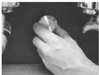
natural_image
Close-up of a gloved hand holding a small metallic object against a dark background (no visible text or symbols)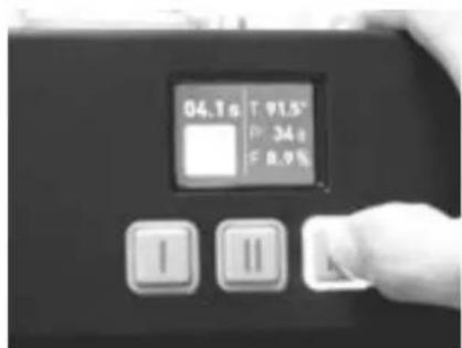
14.6.6 Release firmware
natural_image
Black-and-white photo of industrial equipment including pressure gauges and a conveyor belt, with blurred storage shelves in the background (no visible text or symbols)User manual
1 Espresso machine equipment 61
2 General warnings 62
3 Preparing for installation 68
4 Commissioning and use of the equipment 70
5 Description of the machine 72
6 Brew group display 74
7 Preparing an espresso coffee 76
8 Preparing hot milk 77
9 Hot water supply 78
10 Use of the cup warmer 79
11 Use of the MCS 81
12 Flow regulation 82
13 Periodic maintenance by the user 84
14 Displaying useful information 89
15 Turning the brew groups and boiler on and off 96
16 Programming 98
17 Alarms 105
Wiring diagram 222
Identification plate
DALLA CORTE
DALLA CORTE S.R.L. VIA ZAMBELETTI, 10 20021 BARANZATE (ITALY) MADE IN ITALY

SERIAL N CXXXXXXXXX YEAR 2018 MODEL DC-PROXT X GROUPS
Maximum water pressure 0.6MPa Coffee circuit pressure 1,1Mpa
I XX 0,15Mpa 380 - 400 V 3N 50/60Hz 220 - 230 V 50/60Hz 220 - 230 V 3 50/60Hz 6300 W IPX2

1. Espresso machine equipment
• no. 3-4 filters 2 cups H26
(the number varies according to the model, 2 or 3 groups)
• no. 2 filters 1-cup H23
• no. 1 complete 1 cup portafilter set
• no. 2-3 complete 2 cup portafilter sets
(the number varies according to the model, 2 or 3 groups)
• no. 1 3/8" L70 flex hose
• no. 1 3/8" L150 flex hose
• no. 1 brush to clean the showers
• no. 1 hex key for the shower screws
• no. 2-3 mesh showers
(the number varies according to the model 2 or 3 groups)
• no. 1 black spiral pipe for water drainage
• no. 1 cleaning cloth for external parts
• no. 1 rubber tamper stand
• no. 1 container with detergent tablets
• no. 1 coffee tamper with water flow regulation tool
- Use and maintenance manual
2. General warnings
WARNING
Read the manual carefully before use.
Read the warnings contained in this manual before use, as they provide important information regarding safety, installation, use, and maintenance. Improper use may injure people and animals or damage things for which the manufacturer shall not be liable. Keep this booklet at hand for any further consultation.
The manufacturer reserves the right to modify this manual at any time without notice and without having to update previous versions.
The illustrations in this manual are purely indicative. Dalla Corte reserves the right to make changes to the machines and to manuals without the obligation to update previous versions of machines or manuals.
After removing the packaging, check the integrity of the machine. If in doubt, do not use the machine and contact an authorized technical assistance service. The packaging elements (plastic bags, expanded polystyrene, holders, screws, nails, etc.) must not be left within the reach of children as they are potential sources of danger. Nor should they be discarded in the environment.
Before connecting the machine, make sure that the data on the information plate corresponds to the characteristics of the electric power supplied. The information plate is located below the tray on the left side of the machine. Installation must be carried out in compliance with the regulations in force, according to the manufacturer's instructions, and by qualified personnel.
The manufacturer shall not be liable for any damage caused by the lack of a proper earthing system. For safety reasons, the machine must be connected to a suitable earthing system by a certified electrician who must check that the electrical capacity of the system is suitable for the maximum power stated in the machine's information plate.
The installer must perform the water connections observing the best practices and regulations in relation to hygiene and environmental protection in force in the place of installation.
The device must be supplied with drinkable water according to the provisions in force in the place of installation. For the proper operation and efficiency of the equipment it may be necessary to install an anti-scale water softener.
This assessment must be carried out by the installer of the water softening device following the instructions in the device's instruction manual.
The machine must be used exclusively for the purpose for which it was expressly designed. Any other use is to be deemed improper. The manufacturer shall not be liable for any damage caused by improper, erroneous, or unreasonable use.
The machine is not suitable for use by children, persons with reduced physical, sensory, or mental capacity or anyone lacking suitable knowledge, unless supervision and instruction are provided.
The maximum and minimum storage temperatures must be within the range of 0 °C to +55 °C .
The operating temperature must be within the range of +5 °C to +30 °C.
The use of any electrical equipment always involves the observance of some fundamental rules.
In particular:
- Do not touch the equipment with wet hands or feet.
- Do not use the equipment barefoot.
- Before carrying out any cleaning or ordinary maintenance operation, disconnect the equipment in question from the power supply and turn off the water supply.
- Do not leave the equipment switched on and unattended for long periods (e.g., 1 day or longer).
- Children must always be supervised to make sure they do not play with the equipment.
-
In case of failure and/or malfunction of the machine, switch it off completely, refraining from any direct repair attempt. Contact a manufacturer-authorized Technical Assistance Service.
-
The equipment must be installed in such a way that the highest side is at least 1.2 meters high.
- To guarantee the efficiency of the equipment and its proper operation it is essential to follow the manufacturer's instructions, carrying out all ordinary maintenance.
- To clean the machine, do not wash it with water jets and do not immerse it in water.
- Do not pull the power cord to disconnect the machine from the power supply.
- Do not leave the machine exposed to atmospheric agents (rain, sun, etc.).
- Do not allow the machine to be used by children or unauthorized personnel or anyone who has not read and understood this manual.
- The machine must not be operated by children, persons with reduced physical, sensory, or mental capacity, or anyone lacking suitable knowledge and experience, unless they are properly supervised or instructed by persons with suitable knowledge on how to operate the machine itself safely and efficiently.
Extend the power cable along its entire length to avoid dangerous overheating phenomena.
Do not obstruct the suction and/or dissipation grids, in particular of the cup-warmer.
The power cord must not be replaced by the user. In the case of damage, switch off the machine and contact only qualified personnel to replace it.
If you decide to no longer use this equipment, after having disconnected the machine from the electrical system, cut it.
The continuous sound pressure level is less than 70 dB.
WARNING BURN HAZARD
When using the steam wand, pay close attention, do not put your hands under it, and do not touch it immediately after use.
Field of use and intended use
This espresso coffee machine is designed for professional use by qualified personnel.
This espresso coffee machine is designed for: the preparation of espresso coffee by means of the special brewing heads, hot water supply by means of a special dispenser, and the preparation of cappuccinos by supplying steam from special wands according to the procedures described below. Any other use is improper and therefore dangerous.
Transport and handling
WARNING: IMPACT/CRUSH HAZARD
The machine is transported in wooden crates on pallets individually; the machine is secured to the pallet with bolts.
Before engaging in any transport or handling operation, the operator must be sure to wear safety gloves and shoes and a suit with elastic bands at the wrists and ankles. Transport on pallets must be carried out with a suitable lifting device (e.g. forklift).
During handling operations the operator must continuously ensure that there are no persons or things in the work area.
Slowly lift the pallet about 30 cm from the ground and reach the loading area.
After checking that the work area is free of obstructions, proceed with loading.
Once the machine arrives at the destination, again, make sure that the unloading area is free of persons and things. With a suitable lifting device (e.g. forklift), unload the machine to the ground. To move it to the storage area, the pallet must be lifted about 30 cm from the ground.
3. Preparing for installation
The machine must be installed on a surface that guarantees a safe and stable support. When preparing the installation site, provide an at least 10x10 cm opening A (Fig.1) on the support surface to enable the connections with the necessary utilities in the space below B (Fig.1).
The machine must be exclusively supplied with cold drinkable water in compliance with all national regulations.
The water pressure must range between 0.1 and 0.6 MPa. In the absence of the last requirement, contact the manufacturer for further instructions.
A shut-off valve 1 (Fig.1) must be installed between the water supply and the machine's water supply inlet so as to easily interrupt the water supply if necessary.
Connect the drain siphon 5 (Fig.1), with a minimum diameter of 40 mm, to the drain of the installation premises.
The equipment is supplied without a plug as it is to be installed in a fixed manner to the electrical network. Therefore an omnipolar switch 7 (Fig.1) must be provided for in compliance with all regulations and standards in force.
Connections overview
Fig.1
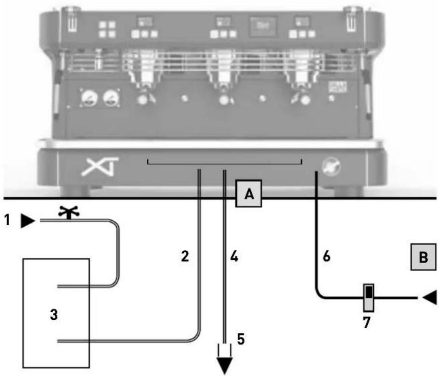
1 Water tap
2 Flexible water hoses
3 Water softener (optional)
4 Drain hose
5 Drain siphon
6 Electric supply cable
7 ON/OFF electrical supply switch
A Hole on support surface
B Under counter space
4. Commissioning and use of the equipment
Carry out the following instructions with the help of the diagram shown in Fig.1.
- Open the water supply tap (1 Fig.1).
- Turn on the electrical power switch (7 Fig.1) and turn the machine's main switch clockwise (1 Fig.2); then verify that the display lights up.
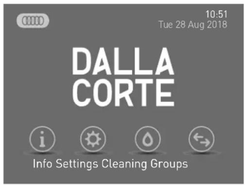
- As soon as the machine is switched on, the autofill function begins to fill the boiler until the working level is reached.
- Once the filling phase is complete, the activated brew groups begin to heat up, the values shown on the display of each group start to flash.
- At the end of the heating phase the values displayed on the display of each group stop flashing, displaying the temperature value set for each
brew group as well as the other parameters in the "Group Display" explained in paragraph 6.
- Immediately after the boiler heating phase begins during which the boiler heating symbol 🐘 will start flashing.
- While the boiler heats up the brew groups may already be used. When the boiler reaches the pre-set temperature, the symbol 0000 stops flashing and the buzzer emits 2 beeps to indicate that all the equipment is in the nominal condition of use.
- When the machine reaches the pre-set operating temperature, BEFORE using it run a washing cycle of the boiler and the brew groups as explained in paragraph 13.
NOTE
The heating sequence above is activated only when the machine is switched on after a complete switch-off by means of the main switch. This heating sequence does not require a significant amount of energy so as to prevent the overloading of the electrical system the machine is connected to.
NOTE
Before switching on the machine, clean all external surfaces, grids, filters, portafilters, and steam wands with dishwashing detergent and then rinse thoroughly.
5. Description of the machine
Fig.2
1 Main switch
2 Adjustable feet
3 Tray
4 Steam wand
5 Steam valve
6 Hot water outlet
7 Boiler pressure gauge
8 Pump pressure gauge
9 Brew group
10 Portafilter
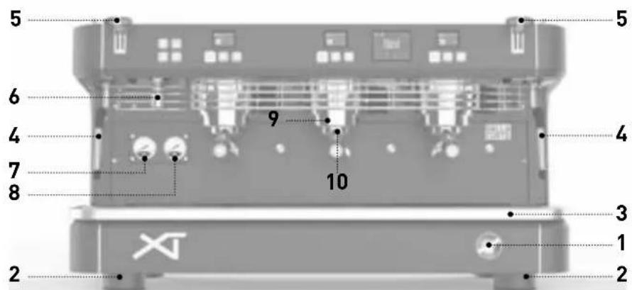

Fig.3
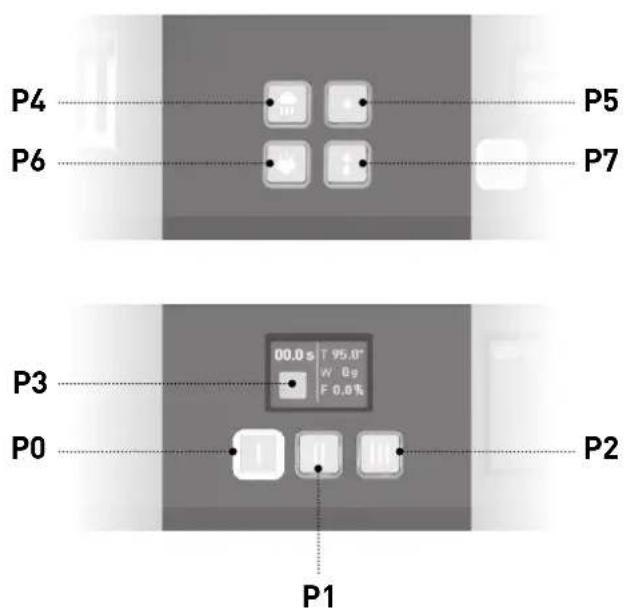
Brew group push-button panel
P0 Selection button 1 (default single small shot coffee)
P1 Selection button 2 (default double small shot coffee)
P2 Selection button 3 (default continuous brewing)
Touch-screen button
P3 Selection button 4 (default flush)
Service push-button panel
P4 Cup warmer switch button
P5 Hot water dose button 1
P6 MCS switch button
P7 2 Hot water dose button 2
6. Brew group display
Brew group display description
Once the brew group reaches the pre-set temperature after the machine is switched on, the following screen is shown on each of the individual brew group displays.
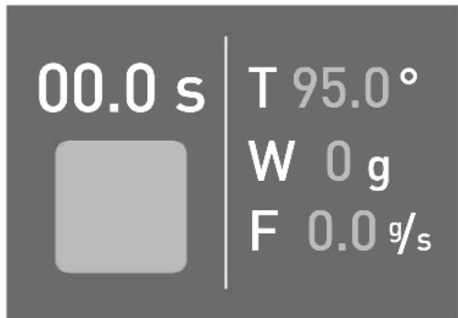
The following information is displayed:
- CHRONOMETER: Total effective brewing time.
- T: Pre-set temperature of the brew group.
- W: Total water weight supplied by the brew group.
- F: Real time flow in grams/second of the water supplied by the brew group.
There is also a yellow button available which can be configured to carry out different functions. By default it is set to activate a quick 1.5s flush of water to clean the shower of any remaining coffee residue.
If the brew group is powered OFF by means of the special menu on the machine's
main display, the screen will no longer display the above parameters and only the word OFF will appear as shown in the image below.

When the brew group is switched back ON, all parameters will flash until the pre-set temperature is reached.
Scale
During a brewing operation, in addition to displaying the total weight of the water used (item W), it is possible to measure the weight of the water delivered to the cup.
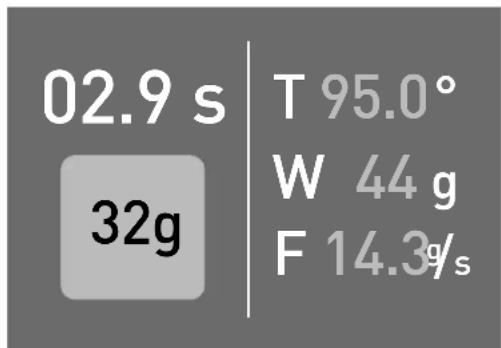
By tapping the P3 button (YELLOW button on the touch-screen) of the relevant group DURING the BREWING PROCESS the grams of water delivered from that moment on is displayed.
This function is used, for example, to measure the coffee in the cup when pressed exactly when the first drops of coffee are delivered.

7. Preparing an espresso coffee
To always make a quality coffee keep the portafilters (10 Fig.2) inserted in the brew groups (9 Fig.1) so as to maintain them at the proper temperature.
To prepare an espresso coffee follow the procedure below:
- Unhook the desired portafilter, avoiding hot metal parts.
- Clean the filter inside the portafilter of any coffee residue.
- Load the filter with fresh coffee with the proper grind size (1 dose of coffee for a single filter, 2 doses of coffee for a double filter).
- Firmly press the coffee with the special manual coffee tamper supplied.
- Clean any residual coffee from the edge of the filter and reattach the portafilter to the brew group.
- Press one of the 2 buttons for the automatic dosage (P0 or P1 Fig.3) of the relevant brew group.

WARNING
Avoid putting your hands under the brew groups when they are in operation. Do not touch any of the metal parts of the brew groups or portafilters as they may cause burns.
8. Preparing hot milk
Pour some milk into a frothing jug/pitcher equipped with a handle. Insert the steam wand (4 Fig.2) in the jug and open the steam valve (5 Fig.2). When the milk reaches the desired temperature, close the steam valve. Once this operation is complete, clean the steam wand with a damp cloth to prevent milk residues from accumulating on it. Afterwards, discharge some steam on the grid of the tray to clean the inside of the wand from milk residues. Protect yourself from the spray with the damp cloth.

WARNING
To manoeuvre the steam wand, use the special insulating handle. Do not open the steam valve without having placed the steam wand in the jug to avoid possible burns.
NOTE
To obtain good quality milk froth it is necessary to follow a specific procedure when warming the milk. This procedure can be learnt from specific video training courses. For safety reasons it is not described in this manual.
9. Hot water supply
This machine is equipped with two hot water dispensing buttons for infusions, dosed by time. Place a container (resistant to temperatures of at least 125 °C) under the hot water outlet (6 Fig.2) and press one of the two hot water supply buttons (P5 or P7 Fig.3). During installation, it is possible to program the quantity and temperature of water to be delivered by each of the aforementioned buttons; this programming must be performed only and exclusively by the installer.

WARNING
Do not press the hot water buttons before placing a container under the outlet so as to prevent burns.
10. Use of the cup warmer
In particular environmental conditions around the equipment, the circulation of cold air may compromise and deviate the normal flow of hot air from the boiler towards the cups, and therefore prevent them from reaching the proper temperature.
The use of cups that are not sufficiently heated when an espresso is pulled may lead to the instantaneous loss of about 25-35 °C and a resulting lukewarm espresso.
The cup warmer built into this machine is electrically powered and can be switched on and off with the P4 button (Fig.3). Only the rear portion of the cup warming tray heats up.
The inverted cup icon is displayed on the screen when the cup warmer is switched on.
The cup warmer has 2 settings: by pressing the P4 button once, the cup warmer operates intermittently providing a medium level of heat. In this case, the cup warmer icon on the display flashes.
By pressing the P4 button a second time, the maximum heating setting is activated and the icon on the display remains fixed.
To switch off the cup warmer, press the P4 button again. At this point, the icon on the display disappears.
11. Use of the MCS
The MCS (Milk Control System) is an automatic milk heating system.
With the MCS it is possible to froth milk at a pre-set temperature. The frothed milk obtained is comparable to that of the best baristas. Using the MCS is as simple as putting a quantity of cold milk in a jug, placing it under the MCS wand, and pressing the P6 button (Fig.3). When the milk has reached the preset temperature (programmed during the installation of the machine), the steam supply will stop automatically and the frothed milk will be ready for use.

WARNING
Do not use the MCS with the steam wand facing the operator or another person.
NOTE
The proper operation of the MCS requires the good cleaning of the steam wand and its nozzle after each use. Depending on the use of the MCS it is also advisable to disassemble the steam nozzle at least twice a day and wash it properly before reinstalling it.
To obtain quality frothed milk it is advisable to pour a quantity of milk in the jug sufficient to cover the end of the steam wand and place it inclined against the wall of the jug to facilitate the formation of a vortex during the heating process.

12. Flow regulation
The machine is equipped with a MFR (Manual Flow Regulator) system that allows the regulation of the water flow supplied by each brew group. To adjust the flow, use the tool featuring a hexagonal end which is incorporated in the special coffee tamper supplied with the machine.
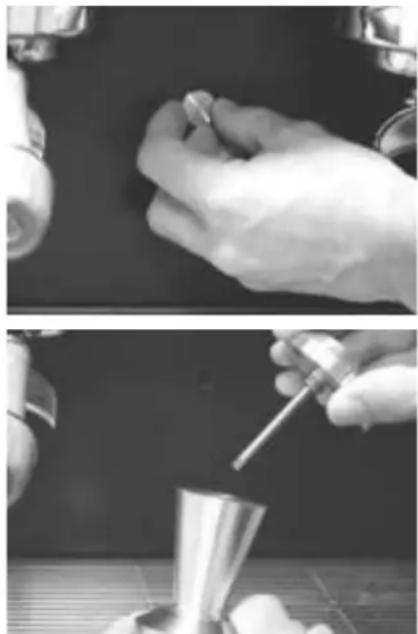
The procedure below shows how to regulate the flow appropriately:
natural_image
Two black-and-white photos showing hands performing a precision tool on a dark surface, with one tool partially visible below (no text or symbols)-
Unscrew the positioning cap on the discharge cover of the group to be adjusted.
-
Remove the tool from the handle of the special coffee tamper.
natural_image
Close-up of hands holding a small metal object with a tool, possibly a teapot or container (no visible text or symbols)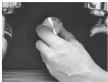
natural_image
Close-up of a gloved hand holding a small metallic object against a dark background (no visible text or symbols)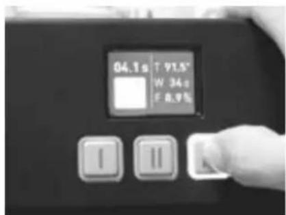
-
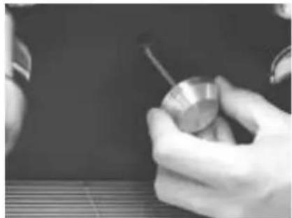
Insert the tool in the hole located in the discharge cover and be sure to position it so that the hexagonal end is well inserted in the screw head.
-
Dispense the water by pressing the relevant water supply button, making sure not to put your hands under the outlet to avoid burns.
-
Unscrew or tighten the screw with the tool to increase or decrease the flow supplied by the brew group in question.
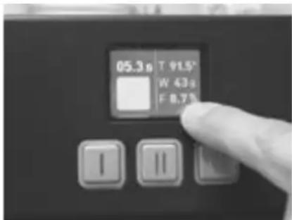
- Check the flow by means of the g/s information indicated next to the letter F on the brew group display.
- At the end of the regulation procedure, screw the cap back onto the discharge cover panel.
13. Periodic maintenance by the user
WARNING
The manufacturer shall not be liable for any injury or damage caused to people, things, or animals as a result of the lack of proper maintenance of the equipment. The efficiency of the equipment is guaranteed only by its proper maintenance. Thus it is important to follow the instructions below to properly carry out maintenance interventions.
Before carrying out any maintenance intervention, be sure to wear high temperature protective gloves.
Cleaning of body parts
Wipe down all body parts with a damp cloth and avoid using abrasive detergents or sponges.
Daily cleaning of parts in contact with coffee
At the end of the work day, unhook the portafilters (10 Fig.2) from the brew groups (9 Fig.2) and remove the filters from the portafilters themselves. Wash all these parts using the brush supplied with the machine to prevent the formation of coffee deposits on both internal and external surfaces. Remove the tray (3 Fig.2) and the relative grid and wash both well.
Cleaning of the brew groups (daily)
This machine is equipped with a 3 minute automatic cleaning system for each brew group.
Proceed as follows to wash each individual group.
- Remove the portafilter from the relevant brew group, remove the relative filter and install the blind filter supplied with the machine.
- Put a cleaning tablet supplied with the machine inside the blind filter and reattach the portafilter to the group head.
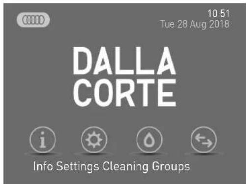
- TapCLEANING on the main display.
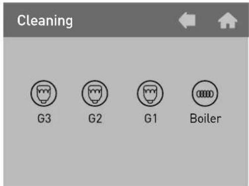
- Then select the brew group to be cleaned.
- Repeat the procedure for the other brew groups or press BACK to return to the main screen.
- After completing the brew group cleaning operations and before using the brew groups, discharge at least 200 cubic centimeters of water from each brew group by pressing the P2 button (continuous delivery) without the portafilter installed.
Boiler washing (daily)
To ensure that the hot water for infusions is always clean and potable, clean the boiler daily.
Proceed as follows to wash the boiler:
- Insert one end of a flexible hose in the hot water outlet on the machine and the other end in the sink.
- Tap CLEANING on the main display and then select BOILER.
- Activating the wash cycle the display returns to the main screen and displays the wash cycle icon.
- During the cleaning of the boiler the groups remain operational.
- This cycle lasts about 30 minutes, so it is advisable to carry it out at the end of the work day.

WARNING
Be sure to carefully fasten the hose used to drain the hot water from the machine to avoid burns.
WARNING
Should the machine remain inactive for more than 1 day, wash the brew groups and the boiler as described above.
Periodic cleaning
Approximately every 3-6 days (depending on the amount of daily work) disassemble the showers and the shower heads located under the brew groups and clean them with the special brush provided. Reassemble these parts paying attention to reposition all the parts correctly, otherwise it could lead to bad coffee extraction and damage to the brew groups.
Softener maintenance
If the machine is connected to a water softener, for the maintenance of the latter see its special instruction manual.
WARNING
The manufacturer and the installer shall not be liable for any damage caused by the lack of and/or incorrect maintenance of the softener.
14. Displaying useful information
The first item seen on the main display concerns useful information.
Tap INFO to access this menu: INFO menu:
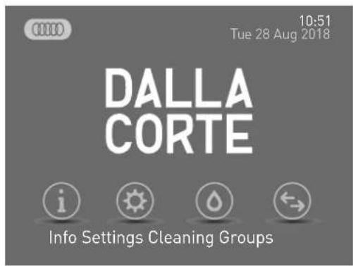
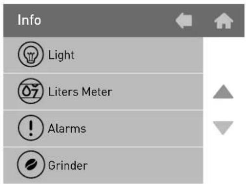
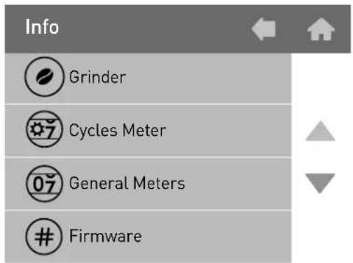
14.1 Lights
This menu item is used to switch the front and back lighting of the espresso machine on and off. Tap the word LIGHTS to turn them on or off.
14.2 Liter meter
This menu allows you to view the li- ter meter function and reset it if ne- cessary. This function can be used to monitor the water softening/purification system for the espresso machine and the reset can easily be performed at each softener regen- ration or cartridge change depen- ding on the system used.
Tap LITER METER to access this menu:
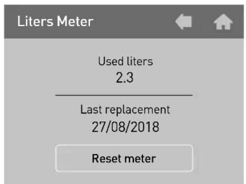
- The current status of the liters count can be seen under the heading "Liters used".
- The item "Last replacement" indicates the date the liter meter was last reset.
- Tap "Reset meter" to reset the liter meter.
Tap BACK to return to the previous menu.
14.3 Alarms
This menu allows you to see if there were any anomalies in the operation of the equipment through the alarms log.
Tap ALARMS to access this menu:
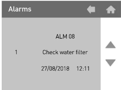
Scroll through all the alarms recorded in the log using the arrows on the right side. In this regard, note that the first alarm to be displayed is the last alarm event.
The maximum memory capacity is 20 alarm events. Once this number is exceeded, the oldest alarm is deleted because it is overwritten by the new one.
Tap BACK to return to the previous menu.
14.4 Grinder (GCS)
This menu displays if the connection of the grinder(s) operates correctly, the progress of the extraction, and any errors.
Tap GRINDER to access this menu:
| Grinder | Meter | Errors |
| 1 | 0 | 0 |
| 2 | 0 | 0 |
- In the Grinder column the grinders in the GCS system are displayed. - In the Meter column the GCS system count is displayed. - The Errors column contains the errors detected by the GCS system with respect to the operations displayed in the meter column.
Tap BACK to return to the previous menu.
14.5 Cycles meter
This menu displays the meters regarding the work cycles of each electromechanical device installed in the equipment.
Tap CYCLES METER to access this menu:
| EV Gr.1 | 321 |
| EV Gr.2 | 46 |
| EV Gr.3 | 99 |
| Pump | 710 |
| EV autofil | 259 |
| EV tea | 290 |
| EV MCS | 1 |
Tap BACK to return to the previous menu.
14.6 General meters
This menu displays all the meters relating to coffee brewing (partial and total), hot water supply, and steam delivery via the MCS (if active).
Tap GENERAL METERS to enter this menu:
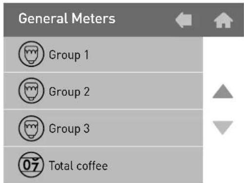
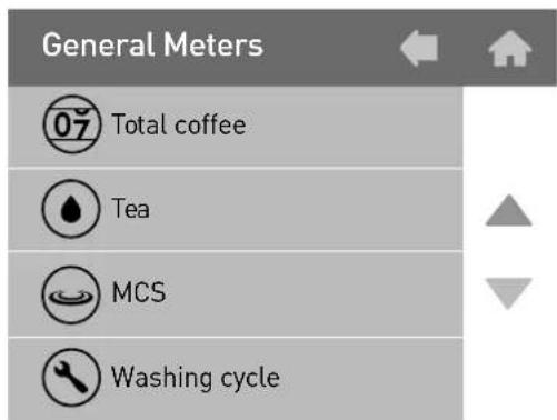
14.6.1 Brew Groups 1-2-3
This menu displays the meters regarding the dosed coffee brewed by the selected brew group.
Tap GROUP 1-2-3 to access this menu:
| Selection | Part. Meter | Tot. Meter |
| S1=KP1 | 14 | 14 |
| S1=KP2 | 190 | 190 |
| S1=KP3 | 0 | 0 |
| S1=KP4 | 0 | 0 |
| Total | 204 | 204 |
- The "Selection" column displays the list of buttons that are counted.
- The "Partial Counters" column displays the count of the partial counters.
- The "Total Counters" column displays the count of the total counters.
Tap BACK to return to the previous menu.
14.6.2 Total coffee
This menu displays the count of all the dosed coffee brewed on all the brew groups.
Tap BACK to return to the previous menu.
14.6.3 Tea
This menu displays the count of all the hot water supplied from the boiler. Tap TEA to access this menu:
Tea

| Selection | Part. Meter | Tot. Meter |
| S1=KP3 | 3 | 3 |
| S1=KP4 | 124 | 124 |
| Total | 127 | 127 |
- The "Selection" column displays the list of buttons that are counted.
- The "Partial Counters" column displays the count of the partial counters.
- The "Total Counters" column displays the count of the total counters.
Tap BACK to return to the previous menu.
14.6.4 MCS
This menu displays the count of steam delivery provided via the MCS.
Tap MCS to access this menu:
MCS

| Selection | Part. Meter | Tot. Meter |
| S1=KP2 | 1 | 1 |
Tap BACK to return to the previous menu.
14.6.5 Washing cycle
This menu displays the counters of the washing cycles carried out in order to check whether the machine operator performs ordinary maintenance on a daily basis.
Tap WASHING CYCLE to enter this menu:
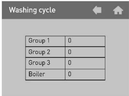
Tap BACK to return to the previous menu.
14.6.6 Firmware release
This menu displays the version of the firmware currently installed on the espresso machine.
Tap FIRMWARE to access this menu:
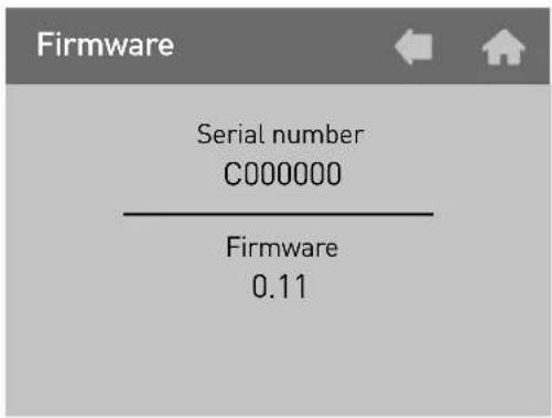
Tap BACK to return to the previous menu.

15. Turning the brew groups and boiler on and off
From the main screen, by selecting GROUPS you access the menu that allows the individual brew groups and the boiler to be turned on and off.
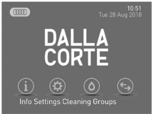
In this menu, by tapping the symbol of the unit to activate and deactivate, a check will appear/disappear in the checkbox below that indicates whether the unit is deactivated or not.
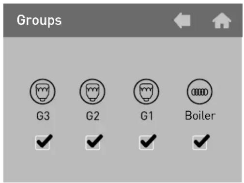
When a brew group is deactivated, the word OFF will be displayed on the individual brew group display of the selected group.
OFF
In contrast, when the boiler is deactivated, the symbol 🐘 will disappear from the main screen.
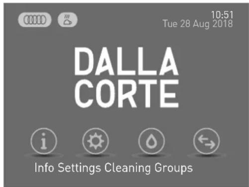
00
10:51
Tue 28 Aug 2018
DALLA CORTE


Info Settings Cleaning Groups
16. Programming
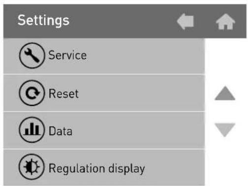
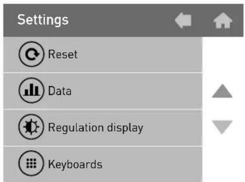
From the main screen, by tapping SETTINGS, you can program different settings such as the group and boiler temperature and the activation of the weekly timer.
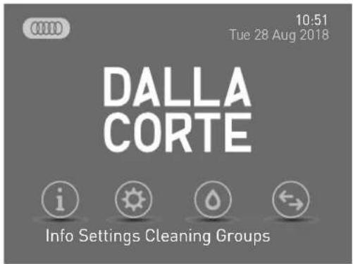
Entering the SETTINGS menu the following screen is displayed:
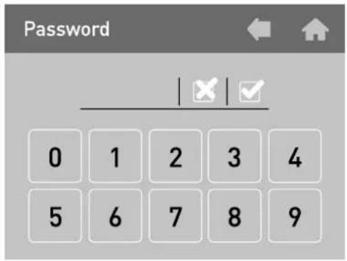
16.0 Password
This screen requests the password for access to the SETTINGS menu.
- Enter the password using the numeric keypad. By default the SERVICE password is 0000.
- Tap) ☑ confirm the password.
At this point the menu can be accessed.
SETTINGS Menu:
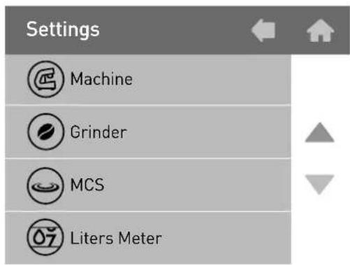
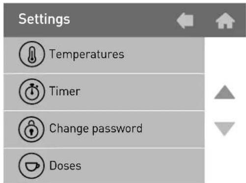
16.1 Temperatures
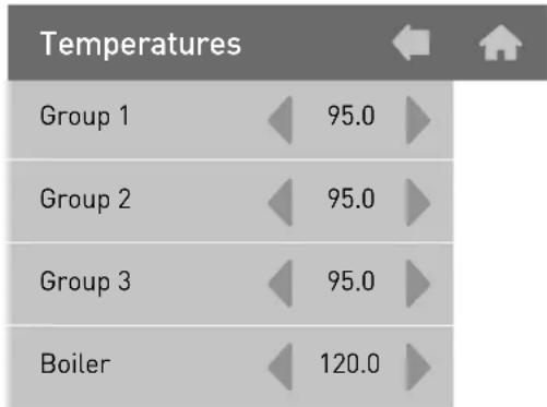
This menu is used to access the screen to adjust the individual brew groups and boiler temperatures.
Tap TEMPERATURES to access this menu:
bar
Temperatures | Group | Temperature (°C) | | :--- | :--- | | Group 1 | 95.0 | | Group 2 | 95.0 | | Group 3 | 95.0 | | Boiler | 120.0 |It is possible to change the temperature of the individual heating elements by means of the arrows on the side of each individual value.
Tap BACK to return to the previous menu.
16.2 Timer
This machine is equipped with a weekly on/off timer for each brew group and for the boiler.
All the timers can be programmed independently from each other and allow the possibility to set the switching on/off and safety mode of each unit on a daily basis.
Tap TIMER to access this menu:
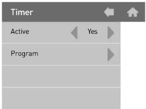
- To activate the timer select "YES" in the "Active" item and proceed by tapping the arrow to the right of "Program".
16.2.1 Timer Programming
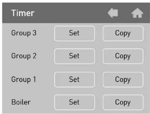
Tap the SET key next to the brew group/boiler to be programmed.
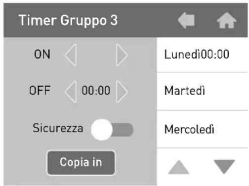
In the programming screen it is possible to select the days of the week and the relative times for the automatic timer to turn on and off.
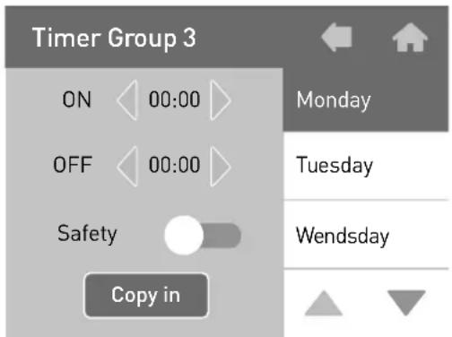
- On the right select the day you wish to program. Once selected, the background will become black. Scroll through the week using the arrows at the bottom right.

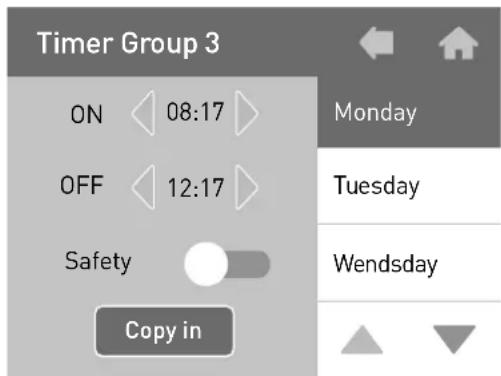
- With the yellow arrows on the sides of the ON and OFF values, set the time at which the brew group/boiler should switch on/off.
-
The "Safety" mode switch has two positions:
-
OFF: The brew group/boiler will remain completely switched off.
- ON: The boiler unit will remain in safety mode at a temperature of 60 °C for the brew group and 80 °C for the boiler.
- Tap COPY IN and then tap the next day of the week to copy the same settings.
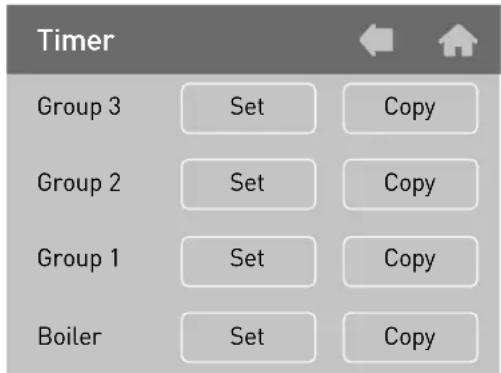
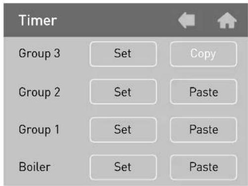
16.2.2 Copy
From the timer screen, you can copy the weekly settings from one unit to another.
- Tap COPY next to the brew group that is already set.
- Tap PASTE next to the brew group to which you want to copy the settings.
- Tap BACK to return to the previous menu.
16.3 Change password
From this submenu it is possible to change the password to access the menu.
Tap CHANGE PASSWORD to access this menu:
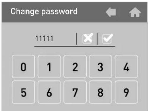
In this screen, the currently set password is displayed.
- To change it, tap the √key and the first digit of the password will start to flash.
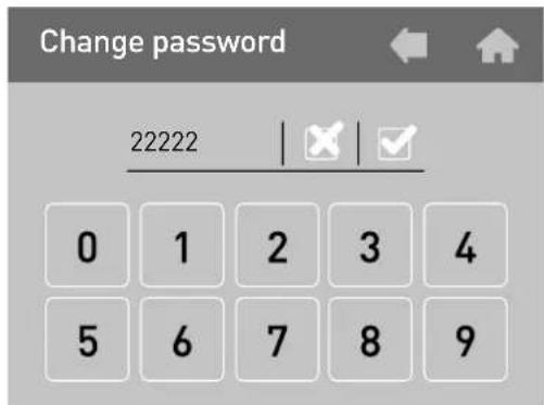
- Type the new password using the numeric keypad. If you make a typing error, tap ✗ to go back to the previous digit.
- Tap BACK to return to the previous menu.

17. Alarms
This equipment is equipped with an electronic control system that, in addition to managing all the operational functions, also verifies the correct operation of all the components.
If an anomaly occurs to a certain function, it is logged and/or displayed by means of an alarm message on the main screen.
WARNING
An alarm may be generated due to the improper use of the equipment. In this case simply correct the method of use to solve the problem.
Some alarms are displayed only and not logged in the system because they are not relevant for the proper operation of the equipment, especially from the point of view of the safety of the operator and the persons or objects in the area surrounding the machine.
| Alarm Cause | Effect | |
| Timeout Gp.1 | This alarm is triggered when brewing on group 1 by means of the P5 continuous delivery button for more than 120 seconds | The brew group is switched off; tap DEL on the display to cancel the alarm |
| Timeout Gp.2 | This alarm is triggered when brewing on group 2 by means of the P5 continuous delivery button for more than 120 seconds | The brew group is switched off; tap DEL on the display to cancel the alarm |
| Alarm Cause Effect | ||
| Timeout Gp.3 | This alarm is triggered when brewing on group 3 by means of the P5 continuous delivery button for more than 120 seconds | The brew group is switched off; tap DEL on the display to cancel the alarm |
| Steam timeout | This alarm is triggered during steam delivery through the MCS when the milk temperature probe does not reach 30 °C within 60 seconds | The steam supply is blocked; tap DEL on the display to cancel the alarm |
| Boiler timeout | This alarm is triggered when the boiler has not reached the temperature of 40 °C within 10 minutes from when it was activated | Boiler heating is blocked; tap DEL on the display to cancel the alarm |
| Boiler sensor interrupted | This alarm is triggered when the boiler temperature sensor is out of range | Boiler heating is blocked; tap DEL on the display to cancel the alarm |
| Boiler sensor failure (short circuit) | This alarm is triggered when the boiler temperature sensor is out of range | Boiler heating is blocked; tap DEL on the display to cancel the alarm |
| High boiler temperature | This alarm is triggered when the boiler temperature sensor has exceeded 127 °C | Boiler heating is blocked; tap DEL on the display to cancel the alarm |
| Alarm Cause Effect | ||
| Steam sensor interrupted | This alarm is triggered when the MCS temperature sensor is out of range | The MCS function is blocked; tap DEL on the display to cancel the alarm |
| Steam sensor failure (short circuit) | This alarm is triggered when the MCS temperature sensor is out of range | The MCS function is blocked; tap DEL on the display to cancel the alarm |
| Gp.1 sensor timeout | This alarm is triggered when brew group 1 has not reached the temperature of 50 °C within 5 minutes from being activated | Brew group 1 heating blocked; tap DEL on the display to cancel the alarm |
| Gp.1 sensor interrupted | This alarm is triggered when the brew group 1 temperature sensor is out of range | Brew group 1 heating blocked; tap DEL on the display to cancel the alarm |
| Gp.1 sensor short circuited | This alarm is triggered when the brew group 1 temperature sensor is out of range | Brew group 1 heating blocked; tap DEL on the display to cancel the alarm |
| High temperature Gp.1 | This alarm is triggered when the temperature of brew group 1 has gone above 120 °C | Brew group 1 heating blocked; tap DEL on the display to cancel the alarm |
| Alarm Cause Effect | ||
| Gp.2 sensor timeout | This alarm is triggered when brew group 2 has not reached the temperature of 50 °C within 5 minutes from being activated | Brew group 2 heating blocked; tap DEL on the display to cancel the alarm |
| Gp.2 sensor interrupted | This alarm is triggered when the brew group 2 temperature sensor is out of range | Brew group 2 heating blocked; tap DEL on the display to cancel the alarm |
| Gp.2 sensor short circuited | This alarm is triggered when the brew group 2 temperature sensor is out of range | Brew group 2 heating blocked; tap DEL on the display to cancel the alarm |
| High temperature Gp.2 | This alarm is triggered when the temperature of brew group 2 has gone above 120 °C | Brew group 2 heating blocked; tap DEL on the display to cancel the alarm |
| Gp.3 sensor timeout | This alarm is triggered when brew group 3 has not reached the temperature of 50 °C within 5 minutes from being activated | Brew group 3 heating blocked; tap DEL on the display to cancel the alarm |
| Gp.3 sensor interrupted | This alarm is triggered when the brew group 3 temperature sensor is out of range | Brew group 3 heating blocked; tap DEL on the display to cancel the alarm |
| Alarm Cause Effect | ||
| Gp.3 sensor short circuited | This alarm is triggered when the brew group 3 temperature sensor is out of range | Brew group 3 heating blocked; tap DEL on the display to cancel the alarm |
| High temperature Gp.3 | This alarm is triggered when the temperature of brew group 3 has gone above 120 °C | Brew group 3 heating blocked; tap DEL on the display to cancel the alarm |
| Gp.1 volume meter failure | This alarm is triggered when group 1 is brewing and the electronic control does not receive signals from the flowmeter corresponding to the same group | Brewing must be stopped manually by pressing the same button used for the brewing in progress |
| Gp.2 volume meter failure | This alarm is triggered when group 2 is brewing and the electronic control does not receive signals from the flowmeter corresponding to the same group | Brewing must be stopped manually by pressing the same button used for the brewing in progress |
| Gp.3 volume meter failure | This alarm is triggered when group 3 is brewing and the electronic control does not receive signals from the flowmeter corresponding to the same group | Brewing must be stopped manually by pressing the same button used for the brewing in progress |
| Alarm Cause | Effect | |
| Level timeout | This alarm is triggered when the autofill function fails to bring the water in the boiler to the pre-established level within the time set in the programming | Autofill function is blocked; tap DEL on the display to cancel the alarm and restart the autofill |
| Safety level | This alarm is triggered when the water level in the boiler drops below the safety sensor's threshold | Boiler heating is blocked; tap DEL on the display to cancel the alarm. If the alarm repeats, contact an authorized technical service provider |
| Grinder service failure | This alarm is triggered when the espresso machine and the grinder connected to are unable to communicate with each other (GCS function) | Grinder auto-regulation blocked; tap DEL on the display to cancel the alarm. If the alarm repeats, contact an authorized technical service provider and temporarily use the continuous dispensing button |
| Cashier serial port failure | This alarm is triggered when the coffee machine and the cashier connected to it are unable to communicate with each other | All brewing is blocked; tap DEL on the display to cancel the alarm. If the alarm repeats, contact an authorized technical service provider |
| Alarm Cause Effect | ||
| Data loss | This alarm is triggered when there is a data loss in the EEPRO, that is, when all the settings defined during installation are lost and the machine returns to the factory defaults | Tap DEL on the display to cancel the alarm and contact an authorized technical service provider |
| Clock failure | This alarm is triggered when the clock's internal module does not work; as a result the timer, if active, is automatically deactivated | Tap DEL on the display to cancel the alarm.If the alarm repeats, contact an authorized technical service provider |
| CPU serial port failure | This alarm is triggered when the serial transmission between the electronic board of the front panel and the power board are no longer able to communicate with each other | Equipment completely blocked.If the problem persists after an attempt to reset the equipment via the general switch, contact an authorized technical service provider |
| 24V alarm | This alarm is triggered when the required supply of 24 volt voltage necessary for the operation of all internal devices is not present | Equipment completely blocked.If the problem persists after an attempt to reset the equipment by means of the general switch, contact an authorized technical service provider |

natural_image
Black-and-white photo of industrial equipment including pressure gauges and a conveyor belt, with blurred storage shelves in the background (no visible text or symbols)Benutzerhandbuch
Maximum water pressure 0.6MPa Coffee circuit pressure 1,1Mpa
I XX 0,15Mpa 380 - 400 V 3N 50/60Hz 220 - 230 V 50/60Hz 220 - 230 V 3 50/60Hz 6300 W IPX2

natural_image
Two black-and-white photos showing hands performing a precision tool on a dark surface, with one tool tip emerging from a metallic cup (no text or symbols visible)natural_image
Close-up of hands holding a small metal object with a tool, possibly a teapot or container (no visible text or symbols)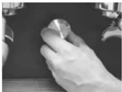
natural_image
Close-up of a gloved hand holding a small metallic object against a dark background (no visible text or symbols)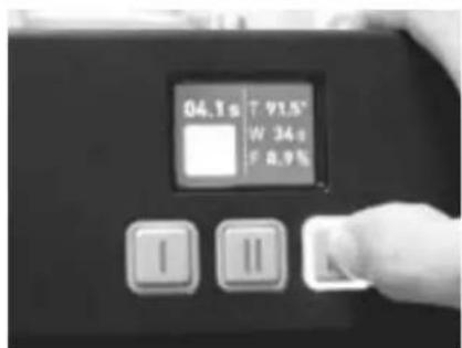
natural_image
Black-and-white photo of industrial equipment including pressure gauges and a conveyor belt, with blurred storage shelves in the background (no visible text or symbols)Manual de usuario
Maximum water pressure 0.6MPa Coffee circuit pressure 1,1Mpa
I XX 0,15Mpa 380 - 400 V 3N 50/60Hz 220 - 230 V 50/60Hz 220 - 230 V 3 50/60Hz 6300 W IPX2

natural_image
Two black-and-white photos showing hands performing a precision tool on a surface, with one tool tip emerging from the other (no visible text or symbols)natural_image
Close-up of hands holding a small metal object with a tool, possibly a teapot or container (no visible text or symbols)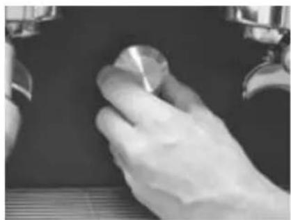
natural_image
Close-up of a gloved hand holding a small metallic object against a dark background (no visible text or symbols)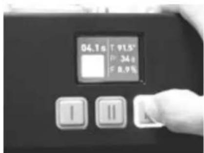
14.6.6 Release firmware
Declaration of conformity
The undersigned company:
Dalla Corte S.R.L.
with registered office in:
Via Zambeletti 10, 20021, Baranzate, MI, Italy
As the manufacturer, hereby declares that:
The DC PRO XT Espresso coffee machine
Complies with the following Community
directives: 2006/42/EC - 2014/35/EU -
The object of the declaration above is in compliance with the relevant Union
harmonization legislation: EN 55014-
1:2006+A1:2009+A2:201; EN 55014-2:2015;
EN 61000-3-2:2014; EN 61000-3-3:2013
EN 60335-1:2012 + A11:2014; EN 60335-2-
64:2016; EN 62233:2008
Dalla Corte S.R.L. is authorized to hold the technical file.
The legal representative
Paolo Dalla Corte

Via Zambeletti 10, 20021, Baranzate, MI, Italy
natural_image
Symbol of a trash bin crossed with a diagonal line, representing no waste or discharge (no text or numbers present)
Information for the correct disposal of the product pursuant to art. 14 of European Directive 2012/19/EU of 4 July 2012
At the end of its useful life, the product must NOT be disposed of together with municipal waste. It can be delivered to the special separate collection centers set up by the municipal administrations. Please contact your municipality, or local authority, for all information regarding the separate collection systems available in your area or contact our authorized dealers. The appropriate separate collection for the subsequent forwarding of the disposed equipment for recycling, processing, and environmentally compatible disposal helps to avoid possible negative effects on the environment and on health and favors the re-use and/or recycling of the materials the equipment is composed of.
For information contact: DALLA CORTE S.r.l. - Via Zambeletti 10 Baranzate (MI) Tél. +39 02 45486443


- DC PRO XT
- Manuale utente
- Release firmware
- User manual
- Identification plate
- DALLA CORTE
- Espresso machine equipment
- General warnings
- WARNING
- WARNING BURN HAZARD
- Field of use and intended use
- Transport and handling
- WARNING: IMPACT/CRUSH HAZARD
- Preparing for installation
- Connections overview
- Commissioning and use of the equipment
- NOTE
- Description of the machine
- Brew group push-button panel
- Touch-screen button
- Service push-button panel
- Brew group display
- Brew group display description
- Scale
- Preparing an espresso coffee
- Preparing hot milk
- Hot water supply
- Use of the cup warmer
- Use of the MCS
- Flow regulation
- Periodic maintenance by the user
- Cleaning of body parts
- Daily cleaning of parts in contact with coffee
- Cleaning of the brew groups (daily)
- Boiler washing (daily)
- Periodic cleaning
- Softener maintenance
- Displaying useful information
- Lights
- Liter meter
- Alarms
- Grinder (GCS)
- Cycles meter
- General meters
- Brew Groups 1-2-3
- Total coffee
- Tea
- MCS
- Washing cycle
- Firmware release
- Turning the brew groups and boiler on and off
- OFF
- Programming
- Password
- Temperatures
- Timer
- Timer Programming
- Copy
- Change password
- Alarms
- Benutzerhandbuch
- Manual de usuario
- Information for the correct disposal of the product pursuant to art. 14 of European Directive 2012/19/EU of 4 July 2012
Brand : Dalla Corte
Model : XT Classic
Category : Coffee machine